HMMA 850 NAAMM 02 00 METAL DOORS & FRAMES Fire-Rated 8d FOURTH EDITION GUIDE SPECIFICATIONS FOR DETENTION SECURITY HOLLOW METAL DOORS AND FRAMES A Division of NATIONAL ASSOCIATION OF ARCHITECTURAL METAL MANUFACTURERS NAAMM 02 00 METAL DOORS & FRAMES Fire-Rated 8d FIRE - RATED HOLLOW METAL DOORS AND FRAMES THIRD EDITION -00 HOLLOW METAL MANUAL NAAMM STANDARD
Transcript
HMMA 850N
AA
MM
02 00
ME
TA
L D
OO
RS
& F
RA
ME
SF
ire-R
ated
8d
FOURTH EDITION
GUIDE SPECIFICATIONSFOR DETENTION SECURITY
HOLLOW METALDOORS AND FRAMES
A Division of
NATIONAL ASSOCIATION OFARCHITECTURAL METAL MANUFACTURERS
NA
AM
M 0200
ME
TA
L DO
OR
S &
FR
AM
ES
Fire-R
ated8d
FIRE - RATEDHOLLOW METAL
DOORS AND FRAMESTHIRD EDITION
-00
HOLLOWMETAL
MANUALNAAMMSTANDARD
DISCLAIMER
This Manual was developed by representative members of andapproved by the Hollow Metal Manufacturers Association(HMMA) Division of the National Association of ArchitecturalMetal Manufacturers (NAAMM) to provide their opinion and guid-ance on the specification and use of fire-rated hollow metal doorsand frames. This Manual contains advisory information only andis published as a public service by NAAMM. NAAMM disclaims allliability of any kind for the use, application or adaptation of mate-rial published in this Manual.
Purchasers of NAAMM Standards may receive current informa-tion on all NAAMM Standards by calling or writing The NationalAssociation of Architectural Metal Manufacturers.
National Association of Architectural Metal Manufacturers8 South Michigan Avenue • Chicago, Illinois 60603 • 1-312-332-0405
Fax 1-312-332-0706 • Website: www.naamm.org
Copyright (c) 1974, 1983, 2000National Association of Architectural Metal Manufacturers
All Rights Reserved
CONTENTS
GENERAL INFORMATION . . . . . . . . . . . . . . . . . . . . . . . . . . . . . . . . . . . . . . . . . . . Section 1Protection of Wall OpeningsBasic RequirementsClassification of Fire DoorsFire TestsListing, Labeling and Certification OrganizationsDesign LimitationsLocal Regulations; The Architect’s ResponsibilitiesGuidelines for Proper UsageRanges of Types and Sizes AvailableLabels for Hollow Metal Fire Doors and FramesRepresentative Types of Hollow Metal Fire DoorsLabeled Glazing Materials for Hollow Metal Fire DoorsRepresentative Types of Fire Door FramesLabeled Materials for Transom, Sidelight and Window AssembliesReferences
HARDWARE FOR SWINGING FIRE DOORS . . . . . . . . . . . . . . . . . . . . . . . . . . . . . Section 2General Hardware RequirementsBuilders Hardware for Singles and Pairs of DoorsBuilders Hardware for Pairs of DoorsHardware Code Summary
FIRE - RATED DOORS AND FRAMES . . . . . . . . . . . . . . . . . . . . . . . . . . . . . . . . . . . Section 3Basic Hollow Metal Fire DoorsPairs of Hollow Metal Fire Doors in a Means of EgressTemperature Rise Rated Hollow Metal Fire Doors Double Egress Hollow Metal Fire Doors and FramesStainless Steel Fire DoorsDutch Hollow Metal Fire DoorsLouvered Hollow Metal Fire DoorsThree-Sided Door FramesMultiple Opening Frames and Transom FramesFrames with 1-3/4" (44 mm) Transom Panels Without Transom MullionTransom Frames - with 1-3/4" (44 mm) Transom Panels and Transom MullionTransom Frames - Glazed Transom Frames with Transom Panels and Transom MullionsSidelight Frames - Glazed or PaneledWindow Frames - Glazed or PaneledSpecial Purpose Fire Door and Frame AssembliesProfiles for Fire-Rated Frame ProductAnchors for Fire-Rated Frame ProductSummary - Hollow Metal Fire DoorsSummary - Fire Door Frame Product
FORWORDNAAMM published the first edition of this manual in 1974. This first edition was entitled “Fire-Rated Custom Metal Doors and Frames”. Much progress has beenmade in the development of door and frame assemblies capable of providing fire protection in wall openings since the publication of the first edition. The second edition was published in 1983.
It is the purpose of this third edition to present data on current practices within theindustry with emphasis on the requirements of the National Fire ProtectionAssociation (NFPA) and Model Codes within the United States. Fire testing, listing,labeling and certification services are thoroughly covered. The section on hardware and its properuse with fire-rated doors has been considerably expanded. The section on fire-ratedproducts describes classified doors and frames currently available fromNAAMM/HMMA member companies. It is believed that this third edition will prove to bea valuable reference manual to those responsible for specifying fire protection prod-ucts. NAAMM will welcome any comments regarding the content of the manual andwill appreciate suggestions for improvement of future editions.
NAAMM/HMMA 850-00 FIRE-RATED HOLLOW METAL DOORS AND FRAMES 1-1
1-2 FIRE-RATED HOLLOW METAL DOORS AND FRAMES NAAMM/HMMA 850-00
Protection of Wall Openings
Hollow metal door and frame assemblies play a crucialrole in providing the fire and life safety protectionrequired in any building. There are however a numberof variations in the designs and performance levels ofthese products. Therefore, in order to make the properselection, it is essential that specifiers have adequateinformation on the different fire door and frame assem-blies available.
Fire protection requirements are established by thebuilding code governing the area in which the buildingis to be erected. These requirements will depend onthe uses or occupancy groups within the building (i.e.,the specific locations in the building and the potentialfire hazards of particular areas). Hollow metal fire doorassemblies achieve ratings ranging from 1/3 hour to amaximum of 3 hours which are determined by theexposure limitations of the assembly itself.
This manual provides information needed to select andspecify swinging fire door assemblies to provide thelevel of fire resistance required.
As used in this document, the term “fire doors” refersto swinging hollow metal door and frame productdesigned to limit the passage of flame through the wallopenings they protect.
Section 3 describes swinging hollow metal fire doorsand frames and the following special purpose hollowmetal fire door assemblies:
• Sound Control Assemblies • Detention Security Assemblies • Bullet Resistant Assemblies• Radiation Shielding Door Assemblies
Since manufacturers of hollow metal doors and framesare continually improving existing products and intro-ducing new ones, it is recommended that manufactur-ers be contacted regarding current fire rating capabili-ties if the design criteria desired is beyond the scope ofthe products described in this manual. Contact theNAAMM office at (312) 332-0405, e-mail [email protected] or the web site at www.naamm.orgfor information on currently available fire-rated doorsand frames.
Basic Requirements
Fire protection of a wall opening requires a complete“fire door assembly”.The architect must be certain thatthe entire assembly, which includes the door, frame,glazing, hardware and installation have been proven tobe capable of providing the level of protection requiredby the governing code and is properly labeled. Firedoor assemblies submitted for testing consist of a spe-
cific type of door and/or frame construction and specif-ic types of hardware. It is this particular combination ofelements that is evaluated. Most typical combinationsof these labeled elements are presented in this manu-al.
The basic requirements and limitations affecting theinstallation and maintenance of fire door assembliesare defined in the National Fire Protection Association“Standard for Fire Doors and Fire Windows”,ANSI/NFPA 80. The most common fire protection rat-ings required by North American codes are 3, 1-1/2, 1,3/4 and 1/3 hour, which indicate the duration of testexposure the elements have endured. Labels,Certification or Listing Marks provide evidence thateach specific element has been listed by a nationallyrecognized certification organization having a factoryinspection service and has been constructed asdetailed in the Follow-Up Service Procedures/FactoryInspection Manuals issued by the certification organi-zation.
A temperature rise rating (TRR) shown on a fire doorlabel is in addition to the fire protection rating. It indi-cates a maximum temperature rise, above ambient,developed on the unexposed face of the door at the 30minute point of a Standard Fire Test. Such labels indi-cate that the rise in temperature does not exceed250°F (121°C), 450°F (232°C) or 650°F (343°C).
Temperature rise ratings are not available for doorswith 1/4 inch (6 millimeter) listed wired glass areasexceeding 100 square inches (0.065 square meters) orfor doors provided with louvers. There are howeverlabeled specialty glazing materials available capable ofresisting the passage of heat which are permitted toexceed the 100 square inch restriction.
Labels on doors cover only the design and construc-tion of the doors. A separate label on the frame certi-fies its design and construction.
Typical labels are shown on page 1-8 in the section onListing, Labeling and Certification Organizations.
Table 1 lists some of the requirements of ANSI/NFPA80 and ANSI/NFPA 101. In addition to the data tabu-lated, there are other important requirements whichapply to all fire doors. Among these are the following:
1. Each frame assembly and each door leaf must belabeled.
2. Each fire door must be self-closing or close auto-matically in the event of a fire, unless exempted bycode. They must also be self-latching and remainclosed at the time of fire in order to provide a depend-able barrier against fire.
3. Automatically closing doors may be held open by
NAAMM/HMMA 850-00 FIRE-RATED HOLLOW METAL DOORS AND FRAMES 1-3
a separate, labeled, fail-safe door holder/releasedevice or a hold-open mechanism which is an integralpart of the basic closing device, provided the hold-open mechanism is released by one or a combinationof automatic fire detectors acceptable to the AuthorityHaving Jurisdiction.
4. Power operated fire doors shall be equipped witha detection device which will automatically cut thepower to the operator.The operator will then cause thedoor to close and latch.
5. Fire doors serving in a “required means of egress”from places of assembly having an occupancy load of100 persons or more must be equipped with fire exithardware. Such hardware is listed both for fire andpanic protection. The label is intended to differentiatebetween fire exit hardware and panic exit hardware.Only fire exit hardware is permitted to be used on firedoors.
Classification of Fire Doors
Fire doors are classified by hourly ratings. The hourlyrating indicates the duration of the fire test exposureand is called the “fire protection rating”.
Table 1 provides the relationship between the doorlocation, wall rating and the required hourly rating forthe opening protected (door and frame).
Refer to Tables 4 and 5 on Pages 1-9 and 1-10 for lim-itations on glazing materials permitted in door andframe product.
The local building code specifies the hourly rating forany location. Generally, fire doors and frames thatqualify for a specific rating also qualify for all lower rat-ings.
Fire Tests
The hourly fire ratings for fire door assemblies (doors,frames and hardware) are determined by the length oftime the assemblies satisfactorily withstand a standardfire test. Model and Building Codes, which specify theStandards used to test and evaluate fire door assem-blies, are undergoing significant changes.
Fire door assemblies, since the early 1900’s, havebeen tested to what have evolved into the ANSI/UL10band ANSI/NFPA 252 Standards. These describe boththe test method and pass/fail criteria.The neutral pres-sure plane for these Standards has historically beenlocated at the top of the fire door assembly.
In 1997 the International Conference of BuildingOfficials (ICBO) adopted and published a positivepressure test method for side-hinged doors, UBC 7-2(1997) for the Uniform Building Code (UBC). UL hasdeveloped ANSI/UL10c which addresses all therequirements of the UBC standard. ANSI/UL10c andUBC 7-2 (1997) require the neutral pressure plane tobe located 40 inches (1016 millimeters) from the bot-tom of the fire door assembly.
Other changes, such as the development of positivepressure fire test standards by NFPA, ASTM and theInternational Building Code (IBC), a single ModelCode for the United States are evolving.
FIGURE 1
STANDARD TIME-TEMPERATURE CURVE
Opening
Openings in walls which sepa-rate buildings or divide a single
building into fire areas
Openings in; enclosures of verti-cal communication such as
stairwells or elevator shafts or;in exterior walls subject to
severe fire exposure from out-side the building
Openings in wallsbetween occupancies
Openings in; corridors and roompartitions or; in exterior walls sub-ject to moderate to light fire expo-
sure from outside the building
Openings where smoke controlis a primary consideration forpartitions between a habitableroom and a corridor when thewall is constructed to have afire resistance of more than 1
hour or across corridors wherea smoke partition is required
Note : The local Authority Having Jurisdiction and Building Code specifythe hourly rating for any location
WallRating
4 hour
2 hour
1 hour
1 hour
1 hour
Door/FrameRating
3 hour
11/2 hour
1 hour
3/4 hour
1/3 hour(no hosestream)
TABLE 1
1-4 FIRE-RATED HOLLOW METAL DOORS AND FRAMES NAAMM/HMMA 850-00
The test, which is generally the same in all theseStandards, consists of building the door assembly,complete with hardware, into a masonry, steel or woodstud wall. The door assembly and wall are located onthe face of a gas-fired furnace. Furnace temperature iscontrolled in accordance with the standard time-tem-perature curve shown in Figure 1 (page 1-3) and theneutral pressure plane is located as per the specificStandard requirements.
The points on the curve that determine its characterare shown in Table 2.The exposure time is determinedby the hourly rating required for the door assembly.
For temperature rise rated doors under ANSI/UL10cand UBC 7-2 (1997), a cotton pad is held at the cracks,seams or openings where hot gases may escape dur-ing the first 30 minutes of the test.
Immediately following the required period of fire expo-sure the assembly is removed from the furnace andsubjected to the impact, erosion and cooling effects ofa stream of water of specified nozzle pressure from a2-1/2 inch (63 millimeters) hose with a 1-1/8 inch (28millimeters) nozzle, commonly known as the “hosestream test”. The water pressure and duration of appli-cation for different ratings are shown in Table 3. Firetests of 1/3 hour duration may be conducted withoutthe hose stream.
Fire window frames and glazing materials are tested inaccordance with Underwriters’ Laboratories ANSI/UL9or ANSI/NFPA 257 for negative pressure require-ments. UBC 7-4 (1997) is the positive pressure equiv-alent, with a UL standard being proposed.The furnacetime-temperature curve and hose stream proceduresare the same as those of ANSI/UL10b and ANSI/NFPA252. However, the length of fire exposure is generally
limited to 3/4 hour, except for glass block and specialtypes of glazing designed for longer exposures.Reference should be made to these Standards forother requirements.
Duration ofWater Pressure Application:
Desired At Base of Seconds/SquareRating Nozzle Foot (s/m2) of
PSI (kPa) Exposed Area(1)
3 hours 45 (310) 3.0 (32)
1-1/2 hour and over ifless than 3 hours 30 (207) 1.5 (16)
1 hour and over ifless than 1-1/2 hours 30 (207) 0.9 (10)
Less than 1 hour 30 (207) 0.6 (6)
(1) : The exposed area shall be calculated using the outsidedimensions of the test specimen, including a frame, hangers,tracks or other parts of the assembly if provided, but normally notincluding the wall into which the specimen is mounted. Wheremultiple test specimens are mounted in the same wall, the rec-tangular or square wall area encompassing all of the specimenswill have to be considered as the exposed area since the hosestream must traverse this area during its application.
TABLE 3
WATER PRESSURE AT BASE OF NOZZLE ANDDURATION OF APPLICATION
The following are the general conditions of acceptance ofperformance when subjected to the standard fire tests.
A door assembly shall be considered as meeting therequirements of acceptable performance when itremains in the opening during the fire endurance andhose-stream test (where required) within the followinglimitations.
1. The test assembly shall withstand the fire endurancetest and hose-stream test (where required), withoutdeveloping openings anywhere through the assembly.
2. Dislodging of small portions of glass, not exceed-ing 5 percent of the glass light area, by the hosestream is acceptable.
3. Separation between meeting edges of pairs ofdoors, within the limits specified in 7 and 8 below, areacceptable.
4. Frames shall remain securely fastened to the wallon all sides and shall not permit through openingsbetween frame and adjacent wall or between the frameand doors.
NAAMM/HMMA 850-00 FIRE-RATED HOLLOW METAL DOORS AND FRAMES 1-5
5. The movement of swinging doors shall not result inany portion of the edges adjacent to the door framemoving from their original position, in a direction per-pendicular to the plane of the door, more than thethickness of the door during the first half of the classi-fication period, nor more than 1-1/2 times the doorthickness during the entire classification period or as aresult of the hose stream test. For positive pressuretested assemblies, the movement shall be no morethan the door thickness during the entire classificationperiod, nor more than 1-1/2 times the door thicknessas a result of the hose stream.
6. The movement of swinging doors mounted in pairsshall not result in any portion of the meeting edgesmoving more than the thickness of the door away fromthe adjacent door edge, in a direction perpendicular tothe plane of the doors, during the entire classificationperiod or as a result of the hose stream test.
7. An assembly consisting of a pair of swinging doorsincorporating an astragal shall not separate in a direc-tion parallel to the plane of the doors more than 3/4inch (19.1 millimeters) nor a distance equal to thethrow of a latch bolt at the latch location.
8. An assembly consisting of a pair of swingingdoors, without an overlapping astragal, for a fire andhose stream exposure of 1-1/2 hours or less, shall notseparate along the meeting edges more than 3/8 inch(9.5 millimeters) including the initial clearance betweendoors.
9. An assembly consisting of a single swinging doorshall not separate more than 1/2 inch (12.7 millime-ters) at the latch location.
10. No flaming shall occur on the unexposed surfaceof a door assembly during the first 30 minutes of theclassification period. For positive pressure temperaturerise rated doors sustained flaming of less than 10 sec-onds duration is permitted. For temperature rise rateddoors the assembly shall not permit the passage of hotgases sufficient to ignite the cotton pad during the first30 minutes of exposure.
11. After 30 minutes, some intermittent light flames(approximately 6 inches (152 millimeters) long), forperiods not exceeding 5 minute intervals, may occuralong the edges of the doors.
12. Light flaming may occur during the last 15 minutesof the classification period on the unexposed surfacearea of the door, provided it is contained within a dis-tance of 1-1/2 inches (38.1 millimeters) from a verticaldoor edge, within 3 inches (76.2 millimeters) from thetop edge of the door or within 3 inches (76.2 millime-ters) from the top edge of the frame of a vision panel.
A glazing assembly shall be considered as meeting
the requirements for acceptable performance if itremains in the opening during the fire endurance testand hose stream test (where required), within the fol-lowing limitations:
1. The glazing assembly shall not be loosened fromits fastenings.
2. Movement at the perimeter of operable compo-nents from the initial closed position shall not exceedthe thickness of the frame member at any point.
3. During the fire test exposure, separation of theglass edges from the frame, so as to create an open-ing, is not permitted.
4. Separation of the glass edges from the glazingframe, by movements away from the frame so as tocreate an opening during the hose stream test, shallnot exceed 30 percent of each individual glass lightperimeter.
5. During the hose stream test, openings created byglass breakage in the central area of each glass lightshall not exceed 5 percent of the area of each individ-ual glass light.
“Openings” for the purpose of the above three para-graphs are defined as through holes in the assemblythan can be seen from the unexposed side when look-ing perpendicular through the plane of the assembly atthe location of the suspected opening.
Any variation from the construction tested may sub-stantially change the performance characteristics ofthe assembly. Testing laboratories have procedures forevaluating alternative constructions or features. Whereevaluations determine that such alternatives do notimpact the performance characteristics of the assem-bly, their use will be permitted.
Listing, Labeling and Certification Organizations
Qualified fire doors, frames and windows shall be iden-tified as such only by the presence of a label issued bya certification organization such as UnderwritersLaboratories, Inc. (UL), Intertek Testing Services/Warnock Hersey (ITS/WHI) or Factory Mutual (FM).
Labels appropriate for various conditions and require-ments are provided as evidence that these productshave passed a standard fire test. Certification organi-zations have developed independent policies regard-ing the information which is required on their labels. Allfire labels indicate the certification organization nameand “mark” (logo), the manufacturer (by name, logo orcontrol number), wording such as “Listed”, “Approved”or “Classified”, a description of the product such as“Swinging Fire Door”, “Fire Door Frame” or “FireWindow Frame” and a serial or control number. All fire
1-6 FIRE-RATED HOLLOW METAL DOORS AND FRAMES NAAMM/HMMA 850-00
door labels must indicate the maximum fire rating. Firedoor frame labels may include the maximum fire rating.Labeled frame products installed in drywall partitionsare rated up to 1-1/2 hours unless indicated other-wise on the label. Labeled frame products in all othertypes of walls are rated to 3 hours unless stated other-wise on the label.
The rating of the installed assembly is equal to that ofthe door, frame or hardware, whichever is less. If anyelement of the assembly (door, frame or hardware) isomitted, does not comply with its listed installationrequirements or does not bear a label, the entireassembly is considered non-labeled.
For openings where temperature rise ratings arerequired, the label will include text indicating the maxi-mum TRR, in degrees Fahrenheit, at 30 minutes inaddition to the fire endurance rating. For negative pres-sure tested assemblies, if a temperature rise is notindicated on the label, it exceeds 650 degreesFahrenheit (340 degrees Celsius). Positive pressuretested door labels, under UBC, are required to indicateeither 250°F (121°C), 450°F (232°C), 650°F (343°C)or exceeds 650°F (343°C) temperature rise.
Certification organizations may also require additionalinformation on their specific labels. Examples includedifferentiating between doors reinforced for fire exithardware and those for single-point locks/latches.Certification organizations may require a FactoryIdentification Mark to identify the location of the plantapplying the label. The certification organization mayalso require a description of the product by modelname or number.
Labels are available in a number of materials whichinclude adhesive-backed mylar labels or metal labelswhich can be riveted or welded to the product. Somemember manufacturers provide fire labels which areembossed directly into their products. See Page 1-8 forfacsimiles of door and frame labels.
Underwriters Laboratories, ITS/Warnock Hersey andFactory Mutual evaluate products on the basis of theirperformance under the standard fire endurance andhose stream tests already described.
UL, WHI and FM require that their representatives wit-ness the fire test when conducted at facilities otherthan their own. When inter-laboratory agreementsexist, this requirement may be waived.
Fire testing is only the first stage of the listing and cer-tification process. UL, WHI and FM Follow-Up pro-grams verify labeled product conformance by conduct-ing frequent unscheduled inspections for quality con-trol and product fabrication in the manufacturer’s plant.
Design Limitations
It is essential that the architect recognize the designlimitations imposed on fire door assemblies which arerequired to be fire rated and labeled. Some of theselimitations have already been mentioned, but there areothers, too, which cannot be disregarded.
Hollow metal fire doors and frames must be made ofhot rolled, cold rolled, galvanized, galvannealed orstainless steel. Frames are available in single or dou-ble rabbet profiles. Glazing materials, where permitted,must be labeled for fire resistance.
The selection of hardware is of particular importance.Only hardware which has passed the appropriate fireand hose stream test shall be permitted. The type ofhardware specified may limit the assembly size or itsfire protection rating.
Closing devices are required on all fire doors and theinactive leaf of all pairs must have automatic or self-latching top and bottom bolts except when used onrooms not normally occupied by humans. Refer toANSI/NFPA 80 for exceptions.
All single doors and the active leafs of pairs must beprovided with locks or latches with an active latch boltwhich cannot be held in the retracted position. Whensingle-point latching hardware is used the maximumpermissible door size is governed by the length of thelatch throw. These limitations may differ from manufac-turer to manufacturer, due to differences in construc-tion details.
Panic exit hardware is not permitted on fire doors. Tobe acceptable for use in fire exits, such devices mustalso be listed as fire exit hardware.
These regulations are some of the most important withrespect to hardware. They indicate the complexity ofthe rules affecting design features. For a more com-prehensive and detailed explanation of hardwarerequirements see Section 2, “Hardware for SwingingHollow Metal Fire Doors” and Section 3, “Fire RatedDoors and Frames” in this manual. Also see the hand-book entitled “Hardware for Labeled Fire Doors” pub-lished by the Door and Hardware Institute. Listings forlabeled hardware may be found in the “BuildingMaterials Directory” published by Underwriters’Laboratories, the ITS/Warnock Hersey “Directory ofListed Products” or the Factory Mutual Research“Approval Guide”. Requests for information, clarifica-tion or advice will be welcomed by any member com-pany of the Hollow Metal Manufacturers Association, aDivision of NAAMM.
NAAMM/HMMA 850-00 FIRE-RATED HOLLOW METAL DOORS AND FRAMES 1-7
Local Regulations; The Architect’sResponsibilities
It should be emphasized that the foregoing discussionhas, of necessity, dealt with generally accepted nation-al regulations, but not all of these standards necessar-ily apply in all locations. The Authority HavingJurisdiction generally base their requirements onNFPA Standards, the Model Codes and normallyrequire products to bear fire labels. Such productsmust conform in every respect to the labeling orapproval requirements of the certification organization.
The architect must be knowledgeable of the local codeas well as the regulations imposed by the owner or theinsurance company. The architect must analyze andinterpret the relevant requirements and designate, in thedoor schedule, which openings are to be rated, the levelof protection required and the materials that are accept-able. The architect must resolve, in advance, such con-flicts as may exist between local codes and labelingrequirements and clearly specify what is to be provided,so as to avoid any possible misunderstandings.
The hardware specifier is responsible for ensuring thatthe appropriate type of hardware is used.The door man-ufacturer, who is nationally oriented and is often locatedat some distance from the job site, cannot be expectedto be familiar with all local requirements unless the archi-tect provides this information. It is the architect’s respon-sibility, therefore, not only to see that the building is prop-erly protected from the danger of fire spread, but to fullyinform the door manufacturer as to what is required,under local regulations, to accomplish this.
Guidelines for Proper Usage
The following guidelines should be observed:
1. Ensure that the door schedule includes all essen-tial information regarding fire doors, such as the man-dated test Standard, the required fire endurance rating,temperature rise rating, type of door design, desiredjamb and trim profiles and type of frame anchorage.
2. Specify that doors, frames and hardware be sup-plied by manufacturers subscribing to a nationally rec-ognized certification, labeling or approval services witha Follow-Up Service program.
3. Specify that all doors and frames have the properfire labels or approval symbols attached. Use onlylabeled frames with labeled doors. Use only listedhardware with labeled doors.
4. Ensure that sizes of doors and frames do notexceed those allowed.
5. If the doors and/or frames are to be glazed, besure that the dimensions and areas are within pre-
scribed limits, that only labeled glazing material is usedand that all glazing stops are of approved material.
6. Ensure that the proper types of hardware (hinges,latches, closers, etc.) are specified and that no chains,hook-backs or other devices are installed to preventthe free closing and latching of the door at any time.
7. If unique designs of doors or frames are contemplat-ed, acceptability may have to be proven by testing or eval-uation. Such processes are time consuming and costly.
8. If special frame profiles are used, ensure that theprofile dimensions do not exceed fire rating require-ments and are compatible with the specified hardware.
9. Ensure that combustible floor coverings do notextend through openings protected by 3 hour fire-rateddoor assemblies.
10. Check the requirements of both the local code andthe insurance company involved for any other restric-tive regulations.
11. Ensure that door and frame labels are not altered,removed or relocated in the field.
12. Hardware changes or any alterations to doors orframes made in the field must be done under a recog-nized certification authority field inspection program.
Ranges of Types and Sizes Available
Hollow metal fire doors of all ratings and variousdesigns, as well as a variety of frame types, are sup-plied by member manufacturers, some offering a widevariety, others a more limited choice. Because therequirements for 3 hour assemblies are more severethan those of assemblies having lower ratings, thechoice in such locations is limited to flush unglazeddoors or in certain jurisdictions, lights not exceeding100 square inches (0.065 square meters). (See Table4) The range of types available for the other ratings ismuch broader, and since each manufacturer has itsown methods of construction, each offers a somewhatdifferent selection. As well, since the development andimprovement of fire door design is an ongoing process,and the selection of products changes from time to time.
The leading manufacturers of fire rated doors andframes are members of the Hollow MetalManufacturers Association. Representative types ofdoors and frames offered by member companies areshown on the following pages. Each company providesits own product literature describing in detail the itemsit produces. Before specifying fire door assemblies theliterature of the intended supplier should always byconsulted. The NAAMM website (www.naamm.org)contains a roster with links to member companies.
1-8 FIRE-RATED HOLLOW METAL DOORS AND FRAMES NAAMM/HMMA 850-00
UL AND WHI LABELS USED ON HOLLOW METAL FIRE DOORS
UL AND WHI LABELS USED ON FIRE DOOR FRAME PRODUCT
Note : Manufacturer must also be identified on each product, either by:- a supplementary label bearing the manufacturer’s name and address,- a combination label bearing the required information along the manufacturer’s name and address or- a label bearing the manufacturer’s procedure, file or reference number
NAAMM/HMMA 850-00 FIRE-RATED HOLLOW METAL DOORS AND FRAMES 1-9
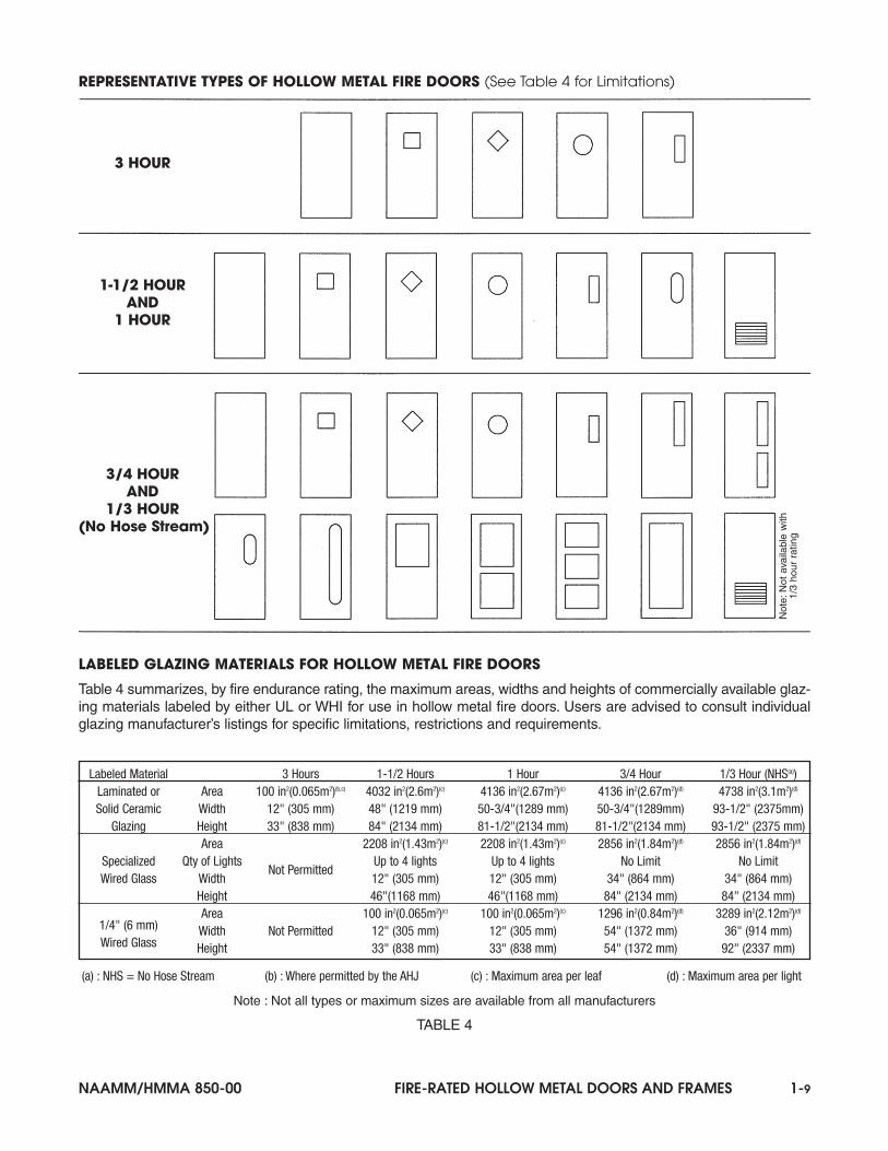
REPRESENTATIVE TYPES OF HOLLOW METAL FIRE DOORS (See Table 4 for Limitations)
3 HOUR
1-1/2 HOURAND
1 HOUR
3/4 HOURAND
1/3 HOUR(No Hose Stream)
LABELED GLAZING MATERIALS FOR HOLLOW METAL FIRE DOORS
Table 4 summarizes, by fire endurance rating, the maximum areas, widths and heights of commercially available glaz-ing materials labeled by either UL or WHI for use in hollow metal fire doors. Users are advised to consult individualglazing manufacturer’s listings for specific limitations, restrictions and requirements.
Labeled Material 3 Hours 1-1/2 Hours 1 Hour 3/4 Hour 1/3 Hour (NHS(a))Laminated or Area 100 in2(0.065m2)(b,c) 4032 in2(2.6m2)(c) 4136 in2(2.67m2)(c) 4136 in2(2.67m2)(d) 4738 in2(3.1m2)(d)
(a) : NHS = No Hose Stream (b) : Where permitted by the AHJ (c) : Maximum area per leaf (d) : Maximum area per light
Note : Not all types or maximum sizes are available from all manufacturers
TABLE 4
Not
e:N
ot a
vaila
ble
with
1/3
hour
rat
ing
1-10 FIRE-RATED HOLLOW METAL DOORS AND FRAMES NAAMM/HMMA 850-00
REPRESENTATIVE TYPES OF FIRE DOOR FRAME PRODUCT
LABELED MATERIALS FOR TRANSOM, SIDELIGHT AND WINDOW ASSEMBLIES
Table 5 summarizes by fire endurance rating, the maximum individual areas, widths and heights of commercially available materials labeled by either UL or WHI for use in transom, sidelight and window assemblies. Users areadvised to consult individual glazing manufacturer’s listings for specific limitations, restrictions and requirements.
Specialized Width Not Permitted Not Permitted Not Permitted 106" (2692 mm) 106" (2692 mm) Wired Glass Height 106" (2692 mm) 106" (2692 mm)
Area 1296 in2(0.84 m2) 5268 in2(3.4m2)1/4" (6 mm) Width Not Permitted Not Permitted Not Permitted 54" (1372 mm) 110-3/8"(2804mm)Wired Glass Height 54" (1372 mm) 110-3/8"(2804mm)
(a) : NHS = No Hose Stream Note : Not all types or maximum sizes are available from all manufacturers
TABLE 5
3 HOUR
1-1/2 HOUR AND 1 HOUR Any 3 Hour Frame Assembly Plus:
3/4 HOUR AND 1/3 HOUR (No Hose Stream) Any 3, 1-1/2 or 1 Hour Frame Assembly Plus:
Three Sided Frames(Center Mullion Optional)
Frames with 1-3/4" (44mm) HollowMetal Panels (no transom bar)
Panel at Headof Frame
Transom Frames with 1-3/4" (44mm)Hollow Metal Panels or 3/8" to 3/4"
(9.5 to 19mm) Solid Panels
Multiple Opening Frame Assemblies (Combinations of Singles and/or Pairs) Sidelight Frames with 3/8" to 3/4" (9.5 to 19mm)Solid Panels or Labeled Glazing Materials
Transom Frames withLabeled Glazing Materials
Sidelight Frames with Labeled Glazing Materials and/or Panels Windows with LabeledGlazing Materials
NAAMM/HMMA 850-00 FIRE-RATED HOLLOW METAL DOORS AND FRAMES 1-11
REFERENCES
BUTTS AND HINGES, ANSI A156.1
American National Standards Institute, Inc.11 W. 42nd Street New York City, NY 10036Telephone : (212) 642-4900E-mail : [email protected] : http://www.ansi.org
LABORATORY MEASUREMENT OF AIRBORNESOUND TRANSMISSION LOSS OF BUILDING PARTITIONS, ASTM E 90
CLASSIFICATION FOR DETERMINATION OFSOUND TRANSMISSION CLASS, ASTM E 413
American Society for Testing & Materials100 Barr Harbor DriveWest Conshohocken, PA 19428-2959Telephone : (610) 832-9585E-mail : [email protected] : http://www.astm.org
HARDWARE FOR LABELED FIRE DOORS
Door and Hardware Institute 14150 Newbrook DriveSuite 200Chantilly, VA 20151-2222Telephone : (703) 222-2010E-mail : [email protected] : http://www.dhi.org
FACTORY MUTUAL APPROVAL GUIDE(published annually with quarterly supplements)
Factory Mutual Engineering & Research Corporation 1151 Boston-Providence TurnpikeNorwood, MA 02062Telephone : (617) 255-4682E-mail : -Website : http://www.factorymutual.com
HOLLOW METAL TECHNICAL AND DESIGN MANUAL
National Association of ArchitecturalMetal Manufacturers8 South. Michigan AvenueSuite 1000Chicago, IL 60603Telephone : (312) 332-0405E-mail : [email protected] : http://www.naamm.org
STANDARD FOR FIRE DOORS AND FIRE WINDOWS, ANSI/NFPA 80
CODE FOR SAFETY TO LIFE FROM FIRE INBUILDINGS AND STRUCTURES, ANSI/NFPA 101
RECOMMENDED PRACTICE FOR THE INSTALLATION OF SMOKE-CONTROL DOORASSEMBLIES, NFPA 105
STANDARD ON TYPES OF BUILDING CONSTRUCTION, ANSI/NFPA 220
STANDARD METHODS OF FIRE TESTS OF DOORASSEMBLIES, ANSI/NFPA 252
STANDARD FOR FIRE TEST FOR WINDOW ANDGLASS BLOCK ASSEMBLIES, ANSI/NFPA 257
National Fire Protection AssociationOne Batterymarch ParkP.O. Box 9101Quincy, MA 02269-9101Telephone : (617) 770-3000E-mail : [email protected] : http://www.nfpa.org
FIRE TESTS FOR WINDOW ASSEMBLIES, ANSI/UL 9
FIRE TESTS OF DOOR ASSEMBLIES, ANSI/UL 10b
FIRE TESTS OF DOOR ASSEMBLIES UNDERPOSITIVE PRESSURE, ANSI/UL 10c
BULLET RESISTING EQUIPMENT, ANSI/UL 752
AIR LEAKAGE TESTS OF DOOR ASSEMBLIES,UL 1784
BUILDING MATERIALS DIRECTORY(published annually with supplements)
2-2 FIRE-RATED HOLLOW METAL DOORS AND FRAMES NAAMM/HMMA 850-00
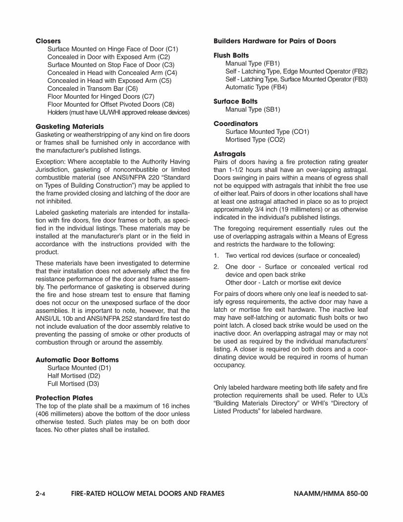
General Hardware Requirements
Hardware requirements for fire doors are specified inANSI/NFPA 80, “Standard for Fire Doors and FireWindows”. This Standard refers to hardware for firedoors as “Builders Hardware” and “Fire DoorHardware”.
Builders hardware is applied only to swinging doorsand consists of the items referenced in Tables 6 and 7.These include: hinges; single, two and three pointlocks or latches; top and bottom bolts; and doorclosers. Within the category of “Builders Hardware” is“Fire Exit Hardware”.
Fire exit hardware consists of exit devices which havebeen labeled both for fire and panic protection.
Labeled hardware for fire doors is required for all fire-rated openings from 1/3 hour to 3 hours.
When positive pressure tested doors and frames arespecified, hardware tested to ANSI/UL10c or UBC 7-2(1997) is also required.
The following is a summary of hardware for swingingflush hollow metal doors. The alpha-numeric codeshown in parentheses following each hardware item isused in the Fire-Rated Doors and Frames Section toindicate approved devices for different door assemblies.
Hinges and Pivots shall be provided as specified inTable 6.
Builders Hardware for Singles and Pairs of Doors
Hinges (Steel)Butt Type
Full Mortise (H1)Half Mortise (H2)Half Surface (H3)Full Surface (H4)
3, 11/2, 3/4, 1/3 3 (914) 7 (2134) 4 (102) 0.105 (2.67) Steel, mortise or surface (labeled self-closing spring type)
Notes(1) : Doors up to 5 feet (1524 mm) in height shall be provided with two hinges and an additional hinge for each additional 2'6" (762 mm) of door
height or fraction thereof. The distance between hinges shall not exceed 2'6" (762 mm) unless tested otherwise. Where self closing springtype hinges are used, at least two shall be provided for each leaf.
(2) : All hinges or pivots, except spring hinges, shall be of the ball bearing type. Hinges or pivots employing other than anti-friction bearing sur-faces shall be permitted if they meet the requirements of ANSI A156.1, “Standard for Butts and Hinges”. Self closing spring hinges shall belabeled.
(3) : 41/2 in. (114 mm) high, 0.180 in. (4.57 mm) thick hinges shall be permitted for use on wide and heavy doors or doors that are subjected toheavy use or unusual stress.
(4) : Some manufacturers can provide fire doors with hinges of lighter weight (thickness) that are not of the ball bearing type where they are partof a labeled assembly, meet the test requirements of ANSI A156.1, “Standard for Butts and Hinges” and have been tested to a minimum of350,000 cycles.
(5) : Pivot sets made up of components that are smaller or of a lighter weight (thickness) than shown above shall be permitted to be used, providedthey meet the requirements of ANSI A156.4, “Door Controls (Closers)” and are in accordance with the manufacturer’s label service procedure.
TABLE 6
MORTISE, SURFACE AND SELF CLOSING SPRING HINGES OR PIVOTS FOR 1-3/4" (44 mm) THICK DOORS(1-5)
NAAMM/HMMA 850-00 FIRE-RATED HOLLOW METAL DOORS AND FRAMES 2-3
Lock, Latches and Deadbolts
Mortise Latch or Lock (Single and Three Point) (L1)Cylindrical (Bored) Latch or Lock (L2)Pre-Assembled Latch or Lock (L3)Mortise Deadlock (L4) (See Exceptions)Cylindrical (Bored) Deadlock (L5) (See Exceptions)Electromechanical/Electric Strike (L6)Electromechanical/Electric Latch (L7)
Fire Exit HardwareSingle Doors
Rim Type (EH1)Mortise Type (EH2)
Two Single Doors with Welded or Removable MullionRim Type (EH1)Mortise Type (EH2)
Pairs of DoorsRim Type with Removable Mullion Behind Doors (EH1)Mortise Type (EH2)Surface Vertical Rod Type (EH3)Concealed Vertical Rod Type (EH4)
All single doors and the active leaf of all pairs of firedoors are permitted to be provided with an active latchbolt (one that cannot be held in a retracted position) asspecified in Table 7.
Exception: Doors other than those used in means ofegress are permitted to be provided with dead bolts inaddition to the active latch or bolts or as otherwise per-mitted by the Authority Having Jurisdiction.
Exception: Locks with dead bolts which are intercon-nected with latch bolts and retract when the latch boltis retracted are permitted to be used on fire doors with-in a means of egress.
Exception: Latching arrangements that do not providepositive latching in the normal mode are permitted tobe used provided that in a fire emergency, the doorbecomes positively latched by means of an automaticfail-safe device that is activated by an automatic firedetector.
Where both leafs are required for exit purposes, theyshall be provided with labeled fire exit hardware.
Exception: Where acceptable to the Authority HavingJurisdiction, pairs of doors not provided with an astra-gal are permitted to have labeled fire exit hardware andan open back strike installed on the inactive leaf andeither labeled fire exit hardware or any labeled latchcapable of being opened by one obvious operationfrom the egress side installed on the active leaf.
Where a pair of doors is needed for the movement ofequipment and where the inactive leaf of pair of doorsis not required for exit purposes, labeled top and bot-tom and self-latching or automatic flush bolts orlabeled two point latches are acceptable.
Exception: Manually operated, labeled top and bottomflush or surface bolts on the inactive leaf of a pair ofdoors shall be permitted to be used when acceptableto the Authority Having Jurisdiction provided they donot pose a hazard to life safety. This provision limitstheir use to rooms not normally occupied by humans(e.g. transformer vaults, storage rooms). The inactiveleaf does not require a closer.
Many hardware manufacturers produce electricallyoperated and/or electronic devices that have beentested and certified from both an electrical and fire pro-tection standpoint and are eligible for use in hollowmetal fire door assemblies.
Single Swing Doors Pairs of DoorsDoor Maximum Minimum Maximum Minimum
Assembly Door Latch Door Latch Inactive LeafFire Rating Height Throw(a) Height Throw(a)
Hours feet (mm) inches (mm) feet (mm) inches (mm)
3, 11/2, 3/4, 1/3 10 (3048) 1/2 (12.7) 10 (3048) 3/4 (19) Labeled Two-Point LatchingDevice or Top and Bottom Bolts
(a) : Unless otherwise tested
TABLE 7
LATCHING DEVICES FOR SWINGING HOLLOW METAL DOORS
2-4 FIRE-RATED HOLLOW METAL DOORS AND FRAMES NAAMM/HMMA 850-00
ClosersSurface Mounted on Hinge Face of Door (C1)Concealed in Door with Exposed Arm (C2)Surface Mounted on Stop Face of Door (C3)Concealed in Head with Concealed Arm (C4)Concealed in Head with Exposed Arm (C5)Concealed in Transom Bar (C6)Floor Mounted for Hinged Doors (C7)Floor Mounted for Offset Pivoted Doors (C8)Holders (must have UL/WHI approved release devices)
Gasketing Materials Gasketing or weatherstripping of any kind on fire doorsor frames shall be furnished only in accordance withthe manufacturer’s published listings.
Exception: Where acceptable to the Authority HavingJurisdiction, gasketing of noncombustible or limitedcombustible material (see ANSI/NFPA 220 “Standardon Types of Building Construction”) may be applied tothe frame provided closing and latching of the door arenot inhibited.
Labeled gasketing materials are intended for installa-tion with fire doors, fire door frames or both, as speci-fied in the individual listings. These materials may beinstalled at the manufacturer’s plant or in the field inaccordance with the instructions provided with theproduct.
These materials have been investigated to determinethat their installation does not adversely affect the fireresistance performance of the door and frame assem-bly. The performance of gasketing is observed duringthe fire and hose stream test to ensure that flamingdoes not occur on the unexposed surface of the doorassemblies. It is important to note, however, that theANSI/UL 10b and ANSI/NFPA 252 standard fire test donot include evaluation of the door assembly relative topreventing the passing of smoke or other products ofcombustion through or around the assembly.
Automatic Door BottomsSurface Mounted (D1)Half Mortised (D2)Full Mortised (D3)
Protection PlatesThe top of the plate shall be a maximum of 16 inches(406 millimeters) above the bottom of the door unlessotherwise tested. Such plates may be on both doorfaces. No other plates shall be installed.
Builders Hardware for Pairs of Doors
Flush BoltsManual Type (FB1)Self - Latching Type, Edge Mounted Operator (FB2)Self - Latching Type, Surface Mounted Operator (FB3)Automatic Type (FB4)
Surface BoltsManual Type (SB1)
CoordinatorsSurface Mounted Type (CO1)Mortised Type (CO2)
AstragalsPairs of doors having a fire protection rating greaterthan 1-1/2 hours shall have an over-lapping astragal.Doors swinging in pairs within a means of egress shallnot be equipped with astragals that inhibit the free useof either leaf. Pairs of doors in other locations shall haveat least one astragal attached in place so as to projectapproximately 3/4 inch (19 millimeters) or as otherwiseindicated in the individual’s published listings.
The foregoing requirement essentially rules out theuse of overlapping astragals within a Means of Egressand restricts the hardware to the following:
1. Two vertical rod devices (surface or concealed)
2. One door - Surface or concealed vertical roddevice and open back strikeOther door - Latch or mortise exit device
For pairs of doors where only one leaf is needed to sat-isfy egress requirements, the active door may have alatch or mortise fire exit hardware. The inactive leafmay have self-latching or automatic flush bolts or twopoint latch. A closed back strike would be used on theinactive door. An overlapping astragal may or may notbe used as required by the individual manufacturers’listing. A closer is required on both doors and a coor-dinating device would be required in rooms of humanoccupancy.
Only labeled hardware meeting both life safety and fireprotection requirements shall be used. Refer to UL’s“Building Materials Directory” or WHI’s “Directory ofListed Products” for labeled hardware.
NAAMM/HMMA 850-00 FIRE-RATED HOLLOW METAL DOORS AND FRAMES 2-5
Locks, Latches and DeadboltsL1 - Mortised Latch or Lock L2 - Cylindrical (Bored) Latch or LockL3 - Pre-Assembled Latch or LockL4 - Mortised DeadlockL5 - Cylindrical (Bored) DeadlockL6 - Electromechanical/Electric StrikeL7 - Electromechanical/Electric Latch
Fire Exit HardwareEH1 - Rim TypeEH2 - Mortise TypeEH3 - Surface Vertical Rod TypeEH4 - Concealed Vertical Rod Type
Closers (Overhead)C1 - Surface Mounted on Hinge Face of DoorC2 - Concealed in Door with Exposed ArmC3 - Surface Mounted on Stop Face of DoorC4 - Concealed in Head with Concealed ArmC5 - Concealed in Head with Exposed ArmC6 - Concealed in Transom Bar
Closers (Floor)C7 - For Hinged DoorsC8 - For Offset Pivoted Doors
Summary - Hollow Metal Fire Doors . . . . . . . . . . 3-24
Summary - Fire Door Frame Product . . . . . . . . 3-25
3-2 FIRE-RATED HOLLOW METAL DOORS AND FRAMES NAAMM/HMMA 850-00
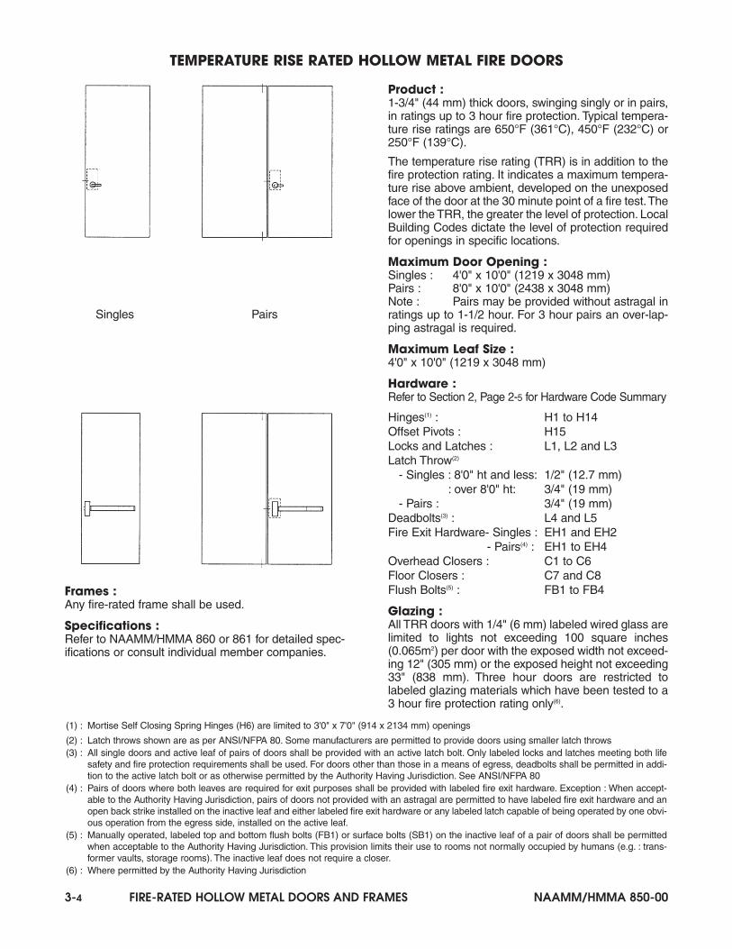
Product :1-3/4" (44 mm) thick doors, swinging singly or in pairs,in ratings up to 3 hour fire protection
Maximum Door Opening :Singles : 4'0" x 10'0" (1219 x 3048 mm)Pairs : 8'0" x 10'0" (2438 x 3048 mm)Note : Pairs may be provided without astragal in rat-ings up to 1-1/2 hour. For 3 hour rated pairs an over-lapping astragal is required.
Maximum Leaf Size :4'0" x 10'0" (1219 x 3048 mm)
Glazing :Refer to Section 1, Table 4, Page 1-9 for requirements
Frames :Any fire-rated frame shall be used.
Specifications :Refer to NAAMM/HMMA 860 and 861 for detailedspecifications or consult individual member companies
BASIC HOLLOW METAL FIRE DOORS
Hardware : Refer to Section 2, Page 2-5 for Hardware Code Summary
Door HeightHardware(2439 mm)
8'0" (2438 mm) and less Over 8'0" (2438 mm) to 10'0" (3048 mm)Hinges H1 to H14 (1) H1 to H5 and H7 to H14Offset Pivots H15 H15Locks
L1, L2 and L3Singles : L1 and L2
and Latches Pairs : L1 onlyDeadbolts (2) L4 and L5 L4 and L5Latch Singles : 1/2" (12.7 mm)Throw (3) Pairs : 3/4" (19 mm)
3/4" (19 mm)
Fire Exit Singles : EH1 and EH2 Singles : EH1 and EH2Hardware Pairs(4) : EH2 to EH4 Pairs(4) : EH2 to EH4Flush Bolts (5) FB1 to FB4 FB1 to FB4Overhead Closers C1 to C6 C1 to C6Floor Closers C7 and C8 C7 and C8
Notes :(1) : Mortise Self Closing Spring Hinges (H6) are limited to 3'0" x 7'0" (914 x 2134 mm) openings(2) : All single doors and active leaf of pairs of doors shall be provided with an active latch bolt. Only labeled locks and latches meeting both life
safety and fire protection requirements shall be used. For doors other than those in a means of egress, deadbolts shall be permitted in addi-tion to the active latch bolt or as otherwise permitted by the Authority Having Jurisdiction. See ANSI/NFPA 80.
(3) : Latch throws shown are as per ANSI/NFPA 80. Some manufacturers are permitted to provide doors using smaller latch throws (4) : Pairs of doors where both leaves are required for exit purposes shall be provided with labeled fire exit hardware.
Exception : When acceptable to the Authority Having Jurisdiction, pairs of doors not provided with an astragal are permitted to have labeledfire exit hardware and an open back strike installed on the inactive leaf and either labeled fire exit hardware or any labeled latch capable ofbeing operated by one obvious operation from the egress side installed on the active leaf.
(5) : Manually operated, labeled top and bottom flush bolts (FB1) or surface bolts (SB1) on the inactive leaf of a pair of doors shall be permittedwhen acceptable to the Authority Having Jurisdiction. This provision limits their use to rooms not normally occupied by humans (e.g. : trans-former vaults, storage rooms). The inactive leaf does not require a closer.
Singles Pairs
NAAMM/HMMA 850-00 FIRE-RATED HOLLOW METAL DOORS AND FRAMES 3-3
Product :1-3/4" (44 mm) thick pairs of doors, swinging in thesame direction, in a means of egress, where bothleaves are required for exit purposes, without astragal,in ratings up to 1-1/2 hour fire protection or with over-lapping astragal up to 3 hour fire protection rating.
Four combinations of hardware are possible to satisfythe requirement that both leaves act as exit doors. OnlyCombination 4 is eligible for 3 hour fire protection rating.
Maximum Door Openings :8'0" x 10'0" (2438 x 3048 mm)
Maximum Leaf Sizes : 4'0" x 10'0" (1219 x 3048 mm)
Latching Hardware (1) : Combination 1 : Surface (EH3) or concealed (EH4)vertical rod fire exit hardware on each leaf.
Combination 2 : Surface (EH3) or concealed (EH4)vertical rod fire exit hardware with an open back strike onone leaf. Mortise (EH2) fire exit hardware on other leaf.
Combination 3 : Surface (EH3) or concealed (EH4)vertical rod fire exit hardware with an open back strikeon one leaf. Any labeled latch (L1, L2 or L3) capable ofbeing opened by one obvious operation from theegress side of the other leaf, where acceptable to theAuthority Having Jurisdiction.
Combination 4 : Surface (EH3) or concealed (EH4)vertical rod fire exit hardware with strike on one leaf.Mortise (EH2) fire exit hardware, coordinator (CO1 orCO2), carry bar and over-lapping astragal on other leaf.
Other Hardware :Refer to Section 2, Page 2-5 for Hardware CodeSummary
Hinges : H1 to H5 and H7 to H14Offset Pivots : H15Locks and Latches : L1, L2, L3 (for Combination 3 only)Latch Throw (2) : 3/4" (19 mm) minimumFlush Bolts : Not permittedOverhead Closers : C1 to C6Floor Closers : C7 and C8
Glazing :Refer to Section 1, Table 4, Page 1-9 for requirements
Frames :Any fire-rated frame shall be used.
Specifications :Refer to NAAMM/HMMA 860 or 861 for detailed spec-ifications or consult individual member companies
PAIRS OF HOLLOW METAL FIRE DOORS IN A MEANS OF EGRESS
(1) : Vertical rod fire exit hardware (EH3 and EH4) are available with top rod only(2) : Latch throws shown are as per ANSI/NFPA 80. Some manufacturers are permitted to provide doors using smaller latch throws.
Combination 1
Combination 2
Combination 3
Combination 4
3-4 FIRE-RATED HOLLOW METAL DOORS AND FRAMES NAAMM/HMMA 850-00
Frames :Any fire-rated frame shall be used.
Specifications :Refer to NAAMM/HMMA 860 or 861 for detailed spec-ifications or consult individual member companies.
Product :1-3/4" (44 mm) thick doors, swinging singly or in pairs,in ratings up to 3 hour fire protection. Typical tempera-ture rise ratings are 650°F (361°C), 450°F (232°C) or250°F (139°C).
The temperature rise rating (TRR) is in addition to thefire protection rating. It indicates a maximum tempera-ture rise above ambient, developed on the unexposedface of the door at the 30 minute point of a fire test.Thelower the TRR, the greater the level of protection. LocalBuilding Codes dictate the level of protection requiredfor openings in specific locations.
Maximum Door Opening :Singles : 4'0" x 10'0" (1219 x 3048 mm)Pairs : 8'0" x 10'0" (2438 x 3048 mm)Note : Pairs may be provided without astragal inratings up to 1-1/2 hour. For 3 hour pairs an over-lap-ping astragal is required.
Maximum Leaf Size :4'0" x 10'0" (1219 x 3048 mm)
Hardware : Refer to Section 2, Page 2-5 for Hardware Code Summary
Hinges(1) : H1 to H14Offset Pivots : H15Locks and Latches : L1, L2 and L3Latch Throw(2)
- Singles : 8'0" ht and less: 1/2" (12.7 mm): over 8'0" ht: 3/4" (19 mm)
- Pairs : 3/4" (19 mm) Deadbolts(3) : L4 and L5Fire Exit Hardware- Singles : EH1 and EH2
- Pairs(4) : EH1 to EH4Overhead Closers : C1 to C6Floor Closers : C7 and C8Flush Bolts(5) : FB1 to FB4
Glazing :All TRR doors with 1/4" (6 mm) labeled wired glass arelimited to lights not exceeding 100 square inches(0.065m2) per door with the exposed width not exceed-ing 12" (305 mm) or the exposed height not exceeding33" (838 mm). Three hour doors are restricted tolabeled glazing materials which have been tested to a3 hour fire protection rating only(6).
TEMPERATURE RISE RATED HOLLOW METAL FIRE DOORS
Singles Pairs
(1) : Mortise Self Closing Spring Hinges (H6) are limited to 3'0" x 7'0" (914 x 2134 mm) openings
(2) : Latch throws shown are as per ANSI/NFPA 80. Some manufacturers are permitted to provide doors using smaller latch throws(3) : All single doors and active leaf of pairs of doors shall be provided with an active latch bolt. Only labeled locks and latches meeting both life
safety and fire protection requirements shall be used. For doors other than those in a means of egress, deadbolts shall be permitted in addi-tion to the active latch bolt or as otherwise permitted by the Authority Having Jurisdiction. See ANSI/NFPA 80
(4) : Pairs of doors where both leaves are required for exit purposes shall be provided with labeled fire exit hardware. Exception : When accept-able to the Authority Having Jurisdiction, pairs of doors not provided with an astragal are permitted to have labeled fire exit hardware and anopen back strike installed on the inactive leaf and either labeled fire exit hardware or any labeled latch capable of being operated by one obvi-ous operation from the egress side, installed on the active leaf.
(5) : Manually operated, labeled top and bottom flush bolts (FB1) or surface bolts (SB1) on the inactive leaf of a pair of doors shall be permittedwhen acceptable to the Authority Having Jurisdiction. This provision limits their use to rooms not normally occupied by humans (e.g. : trans-former vaults, storage rooms). The inactive leaf does not require a closer.
(6) : Where permitted by the Authority Having Jurisdiction
NAAMM/HMMA 850-00 FIRE-RATED HOLLOW METAL DOORS AND FRAMES 3-5
Product :1-3/4" (44 mm) thick pairs of doors swinging in oppo-site directions, in ratings up to 3 hour fire protection.
Double egress assemblies permit traffic flow in bothdirections through the same opening. Where doubleegress doors are used for 1-1/2 hour applications orless, they may be installed without astragals. For 3hour rated double egress doors an over-lapping astra-gal is required.
Maximum Door Opening :8'0" x 10'0" (2438 x 3048 mm)
Maximum Leaf Size :4'0" x 10'0" (1219 x 3048 mm)
Hardware :Refer to Section 2, Page 2-5 for Hardware Code Summary
Hinges : H1 to H5, H7 to H14Offset Pivots : H15Locks, Latches, Deadbolts : Not PermittedFire Exit Hardware(1): EH3 and EH4Overhead Closers : C1 to C6Floor Closers : C7 and C8Flush Bolts : Not Permitted
Glazing :Refer to Section 1, Table 4, Page 1-9 for requirements
Anchors :Anchors are available for new or existing masonry,poured concrete and wood or steel stud partitions. See“Anchors for Fire-Rated Frames”, Page 3-22 for addi-tional information.
Frames :A fire-rated frame listed for use with double egressdoors is required.
Specifications :Refer to NAAMM/HMMA 860 or 861 for detailed spec-ifications or consult individual member companies.
DOUBLE EGRESS HOLLOW METAL FIRE DOORS AND FRAMES
(1) : Both leaves are required for exit purposes, therefore they must be provided with labeled surface (EH3) or concealed (EH4) vertical rod fireexit hardware. There are no exceptions to this for double egress door and frame assemblies.
Typical Elevations
Typical Plan View
Typical Head Alternate Head
TypicalJamb
3-6 FIRE-RATED HOLLOW METAL DOORS AND FRAMES NAAMM/HMMA 850-00
Product :1-3/4" (44 mm) thick, swinging singly or in pairs, stain-less steel doors, in ratings up to 3 hour fire protection.Available in Types 304, 316 or 430 stainless steel.
Maximum Door Opening :Type 304 or 316 - Singles : 4'0" x 8'0" (1219 x 2438mm)
Pairs : 8'0" x 8'0" (2438 x 2438mm)Type 430 - Singles: 4'0" x 10'0" (1219 x 3048mm)
Pairs : 8'0" x 10'0" (2438 x 3048 mm)Note : Pairs may be provided without an astragal inratings up to 1-1/2 hour. For 3 hour rated pairs an over-lapping astragal is required.
Maximum Leaf Size :Type 304 or 316 - 4'0" x 8'0" (1219 x 2438 mm)Type 430 - 4'0" x 10'0" (1219 x 3048 mm)
Hardware:Refer to Section 2, Page 2-5 for Hardware Code Summary
Hinges(1) : H1 to H14Offset Pivots : H15Locks, Latches, Deadbolts(2) : L1, L2, L4 and L5Latch Throw(3)
- Singles : 8'0" ht and less: 1/2" (12.7 mm): over 8'0" ht: 3/4" (19 mm)
- Pairs(4) : EH1 to EH4Overhead Closers : C1 and C3Floor Closers : Not PermittedFlush Bolts(5) : FB1 to FB4
Glazing :Consult individual member companies for requirements
Frames :Any three-sided fire-rated frame shall be used.
Specifications :Refer to NAAMM/HMMA 866 for detailed specifica-tions or consult individual member companies.
STAINLESS STEEL FIRE DOORS
(1) : Mortise Self Closing Spring Hinges (H6) are limited to 3'0" x 7'0" (914 x 2134 mm) openings(2) : All single doors and active leaf of pairs shall be provided with an active latch bolt. Only labeled locks and latches meeting both life safety and
fire protection requirements shall be used. For doors other than those in a means of egress, deadbolts shall be permitted in addition to theactive latch bolt or as otherwise permitted by the Authority Having Jurisdiction. See ANSI/NFPA 80.
(3) : Latch throws shown are as per ANSI/NFPA 80. Some manufacturers are permitted to provide doors using smaller latch throws (4) : Pairs of doors where both leaves are required for exit purposes shall be provided with labeled fire exit hardware.
Exception : When acceptable to the Authority Having Jurisdiction, pairs of doors not provided with an astragal are permitted to have labeledfire exit hardware and an open back strike installed on the inactive leaf and either labeled fire exit hardware or any labeled latch capable ofbeing operated by one obvious operation from the egress side installed on the active leaf.
(5) : Manually operated, labeled top and bottom flush bolts (FB1) or surface bolts (SB1) on the inactive leaf of a pair of doors shall be permittedwhen acceptable to the Authority Having Jurisdiction. This provision limits their use to rooms not normally occupied by humans (eg : trans-former vaults, storage rooms). The inactive leaf does not require a closer.
Singles Pairs
NAAMM/HMMA 850-00 FIRE-RATED HOLLOW METAL DOORS AND FRAMES 3-7
Product :1-3/4" (44 mm) thick, single swing dutch door, withover-lapping astragal, with or without shelf, in ratingsup to 3 hour fire protection.
Maximum Door Opening :4'0" x 8'0" (1219 x 2438 mm)
Hardware :Refer to Section 2, Page 2-5 for Hardware Code Summary
Hinges(1) : H1 to H14Offset Pivots : Not PermittedLocks, Latches, Deadbolts(2) : L1 and L2Latch Throw : 1/2"Fire Exit Hardware : Not PermittedOverhead Closers : C1 to C6, top leaf onlyFloor Closer : Not PermittedFlush Bolts : Not Permitted
Glazing :Consult individual member companies for requirements
Frames :Any fire-rated frame or transom frame shall be used.
Specifications :Refer to NAAMM/HMMA 860 or 861 for detailed spec-ifications or consult individual member companies.
DUTCH HOLLOW METAL FIRE DOORS
(1) : Mortise Self Closing Spring Hinges (H6) are limited to 3'0" x 7'0" (914 x 2134 mm) openings(2) : Each leaf shall be provided with an active latch bolt. Only labeled locks and latches meeting both life safety and fire protection requirements
shall be used. For doors other than those in a means of egress, deadbolts shall be permitted in addition to the active latch bolt or as other-wise permitted by the Authority Having Jurisdiction. See ANSI/NFPA 80.
Top Leaf Latchinginto Strike Jamb
Top Leaf Latchinginto Bottom Leaf
2 hinges per leaf
Single PointLatches
Bottom leaf must latchinto strike jamb
Astragal
Shelf - 1Side Only(Optional)
2 hinges per leaf
Single PointLatches
Bottom leaf must latchinto strike jamb
3-8 FIRE-RATED HOLLOW METAL DOORS AND FRAMES NAAMM/HMMA 850-00
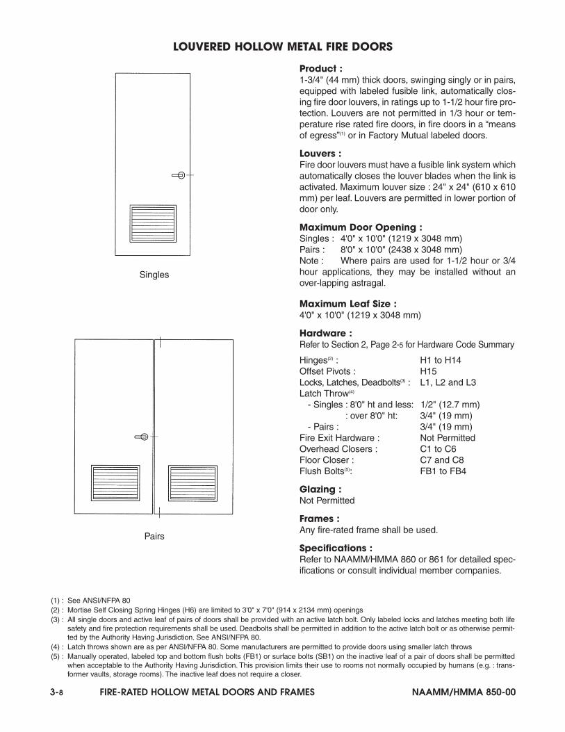
Product :1-3/4" (44 mm) thick doors, swinging singly or in pairs,equipped with labeled fusible link, automatically clos-ing fire door louvers, in ratings up to 1-1/2 hour fire pro-tection. Louvers are not permitted in 1/3 hour or tem-perature rise rated fire doors, in fire doors in a “meansof egress”(1) or in Factory Mutual labeled doors.
Louvers :Fire door louvers must have a fusible link system whichautomatically closes the louver blades when the link isactivated. Maximum louver size : 24" x 24" (610 x 610mm) per leaf. Louvers are permitted in lower portion ofdoor only.
Maximum Door Opening :Singles : 4'0" x 10'0" (1219 x 3048 mm)Pairs : 8'0" x 10'0" (2438 x 3048 mm)Note : Where pairs are used for 1-1/2 hour or 3/4hour applications, they may be installed without anover-lapping astragal.
Maximum Leaf Size :4'0" x 10'0" (1219 x 3048 mm)
Hardware : Refer to Section 2, Page 2-5 for Hardware Code Summary
Hinges(2) : H1 to H14Offset Pivots : H15Locks, Latches, Deadbolts(3) : L1, L2 and L3Latch Throw(4)
- Singles : 8'0" ht and less: 1/2" (12.7 mm): over 8'0" ht: 3/4" (19 mm)
- Pairs : 3/4" (19 mm)Fire Exit Hardware : Not PermittedOverhead Closers : C1 to C6Floor Closer : C7 and C8Flush Bolts(5): FB1 to FB4
Glazing :Not Permitted
Frames :Any fire-rated frame shall be used.
Specifications :Refer to NAAMM/HMMA 860 or 861 for detailed spec-ifications or consult individual member companies.
LOUVERED HOLLOW METAL FIRE DOORS
(1) : See ANSI/NFPA 80 (2) : Mortise Self Closing Spring Hinges (H6) are limited to 3'0" x 7'0" (914 x 2134 mm) openings (3) : All single doors and active leaf of pairs of doors shall be provided with an active latch bolt. Only labeled locks and latches meeting both life
safety and fire protection requirements shall be used. Deadbolts shall be permitted in addition to the active latch bolt or as otherwise permit-ted by the Authority Having Jurisdiction. See ANSI/NFPA 80.
(4) : Latch throws shown are as per ANSI/NFPA 80. Some manufacturers are permitted to provide doors using smaller latch throws(5) : Manually operated, labeled top and bottom flush bolts (FB1) or surface bolts (SB1) on the inactive leaf of a pair of doors shall be permitted
when acceptable to the Authority Having Jurisdiction. This provision limits their use to rooms not normally occupied by humans (e.g. : trans-former vaults, storage rooms). The inactive leaf does not require a closer.
Singles
Pairs
NAAMM/HMMA 850-00 FIRE-RATED HOLLOW METAL DOORS AND FRAMES 3-9
Product :3 hour (maximum) fire door frames, used with firedoors swinging singly or in pairs.
Maximum Door Opening :Singles : 4'0" x 10'0" (1219 x 3048 mm)Pairs : 8'0" x 10'0" (2438 x 3048 mm)Contra-Swing(1) : 4'0" x 8'0" (1219 x 2438 mm)
Maximum Leaf Size :Singles and Pairs : 4'0" x 10'0" (1219 x 3048 mm)Contra-Swing : 4'0" x 8'0" (1219 x 2438 mm)
Mullions :Mullions are optional and may be welded or removable,for either between or behind the door applications.Doors shall not be hinged off removable mullions.
Anchors :Anchors are available for new or existing masonry,poured concrete, structural steel, wood and steel studpartitions. See “Anchors for Fire Rated FrameProduct”, Page 3-22 for additional information.
Specifications :Frames shall be fabricated from hot rolled, cold rolled,galvanized, galvannealed or stainless steel. Refer toNAAMM/HMMA 860, 861 or 866 for detailed specifica-tions or consult individual member companies.
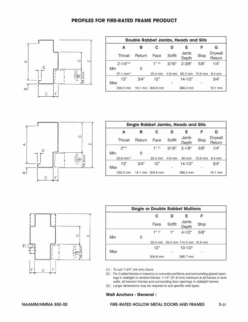
Profiles :Single or double rabbet jambs, heads and mullions.See “Profiles for Fire-Rated Frame Product”, Page3-21 for additional information.
THREE SIDED FIRE DOOR FRAMES
Pair of Doors(No Mullion)
Pair of DoorsWelded or RemovableMullion Behind Doors
2 SinglesWelded or RemovableMullion Between Doors
2 SinglesWelded or RemovableContra-Swing Mullion
Between Doors
Jamb or Head Welded or RemovableMullion Between Doors
Welded or RemovableContra-Swing Mullion
Welded or RemovableMullion Behind Doors
Single RabbetAlternate Profile
(Typ)
1) : Contra-Swing frames limited to 1-1/2 hour fire protection rating
3-10 FIRE-RATED HOLLOW METAL DOORS AND FRAMES NAAMM/HMMA 850-00
Product :1-1/2 hour (maximum) fire door frames and transom frames used with1-3/4" (44 mm) thick fire doors, swinging in combinations of singles,pairs, contra-swing and/or double egress configurations
Maximum Door Opening :Singles : 4'0" x 8'0" (1219 x 2438 mm)Pairs and Double Egress: 8'0" x 8'0" (2438 x 2438 mm)
Maximum Leaf Size :4'0" x 8'0" (1219 x 2438 mm)
Maximum Over-All Unit Size :12'8" width x 8'4" height (3861 x 2540 mm) frames12'8" width x 10'0" height (3861 x 3048 mm) transom frames
Mullions :Vertical mullions at doors may be welded or removable for eitherbetween or behind the door applications. Doors shall not be hingedoff removable mullions. Horizontal and vertical transom mullions mustbe welded.
Transom Material :Refer to Section 1, Table 5, Page 1-10 for requirements and options.
Anchors :Anchors are available for new or existing masonry, poured concrete,structural steel, wood and steel stud partitions. See “Anchors for Fire-Rated Frame Product”, Page 3-22 for additional information.
Specifications :Frames shall be fabricated from hot rolled, cold rolled, galvanized,galvannealed or stainless steel. Refer to NAAMM/HMMA 860, 861 or866 for detailed specifications or consult individual member compa-nies.
Profiles :Single or double rabbet jambs, heads and mullions. See “Profiles forFire-Rated Frame Product”, Page 3-21 for additional information.
MULTIPLE OPENING FRAMES AND TRANSOM FRAMES
Jamb or Head Welded or RemovableMullion Between Doors
Welded or RemovableContra-Swing Mullion
Welded or RemovableMullion Behind Doors
Single RabbetAlternate Profile
(Typ)
NAAMM/HMMA 850-00 FIRE-RATED HOLLOW METAL DOORS AND FRAMES 3-11
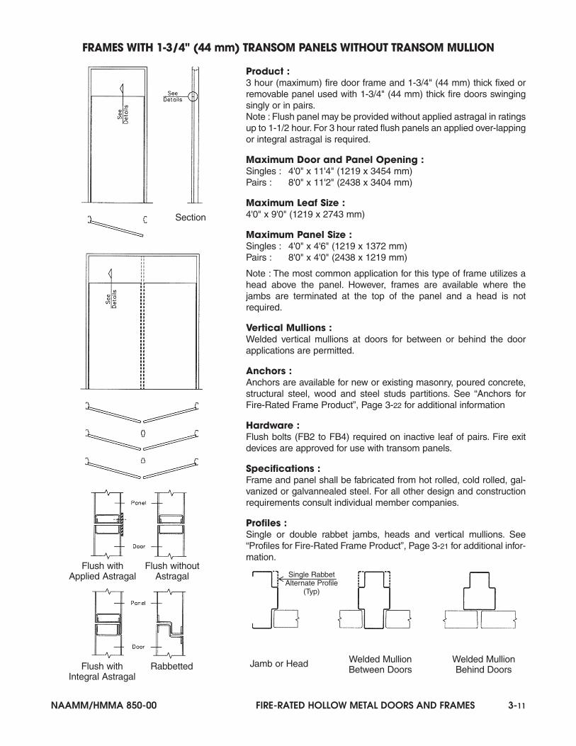
Product :3 hour (maximum) fire door frame and 1-3/4" (44 mm) thick fixed orremovable panel used with 1-3/4" (44 mm) thick fire doors swingingsingly or in pairs.Note : Flush panel may be provided without applied astragal in ratingsup to 1-1/2 hour. For 3 hour rated flush panels an applied over-lappingor integral astragal is required.
Maximum Door and Panel Opening :Singles : 4'0" x 11'4" (1219 x 3454 mm)Pairs : 8'0" x 11'2" (2438 x 3404 mm)
Maximum Leaf Size :4'0" x 9'0" (1219 x 2743 mm)
Maximum Panel Size :Singles : 4'0" x 4'6" (1219 x 1372 mm)Pairs : 8'0" x 4'0" (2438 x 1219 mm)
Note : The most common application for this type of frame utilizes ahead above the panel. However, frames are available where thejambs are terminated at the top of the panel and a head is notrequired.
Vertical Mullions :Welded vertical mullions at doors for between or behind the doorapplications are permitted.
Anchors :Anchors are available for new or existing masonry, poured concrete,structural steel, wood and steel studs partitions. See “Anchors forFire-Rated Frame Product”, Page 3-22 for additional information
Hardware :Flush bolts (FB2 to FB4) required on inactive leaf of pairs. Fire exitdevices are approved for use with transom panels.
Specifications :Frame and panel shall be fabricated from hot rolled, cold rolled, gal-vanized or galvannealed steel. For all other design and constructionrequirements consult individual member companies.
Profiles :Single or double rabbet jambs, heads and vertical mullions. See“Profiles for Fire-Rated Frame Product”, Page 3-21 for additional infor-mation.
FRAMES WITH 1-3/4" (44 mm) TRANSOM PANELS WITHOUT TRANSOM MULLION
Jamb or Head Welded MullionBetween Doors
Welded MullionBehind Doors
Flush withApplied Astragal
Flush withoutAstragal Single Rabbet
Alternate Profile(Typ)
Flush withIntegral Astragal
Rabbetted
Section
3-12 FIRE-RATED HOLLOW METAL DOORS AND FRAMES NAAMM/HMMA 850-00
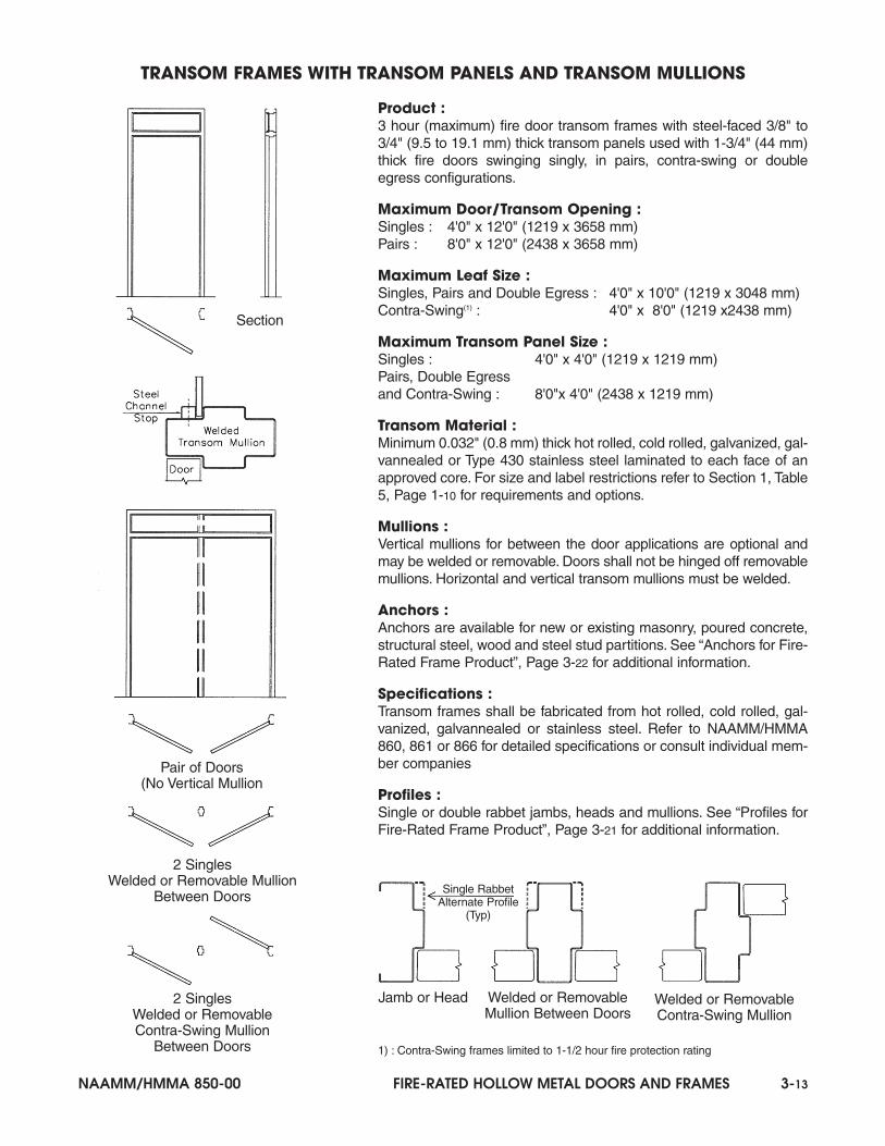
Product :3 hour (maximum) fire door transom frames with 1-3/4" (44 mm) thicktransom panels used with 1-3/4" (44 mm) thick fire doors swingingsingly or in pairs.
Door/Transom Opening :Singles : 4'0" x 11' 10" (1219 x 3607 mm)Pairs : 8'0" x 11' 10" (2438 x 3607 mm)
Maximum Leaf Size :Singles and Pairs : 4'0" x 10'0" (1219 x 3048 mm)Contra-Swing(1) : 4'0" x 8'0" (1219 x 2438 mm)
Maximum Transom Panel Size :Singles : 4'0" x 4'0" (1219 x 1219 mm)Pairs : 8'0" x 4'0" (2438 x 1219 mm)
Transom Material :Transom panels shall be fabricated from hot rolled, cold rolled, galva-nized, galvannealed or Type 430 stainless steel.
Mullions :Vertical mullions for between the door applications are optional andmay be welded or removable. Doors shall not be hinged off removablemullions. Horizontal transom mullion can be welded or removable.
Anchors :Anchors are available for new or existing masonry, poured concrete,structural steel, wood and steel stud partitions. See “Anchors for Fire-Rated Frame Product”, Page 3-22 for additional information.
Specifications :Transom frames shall be fabricated from hot rolled, cold rolled, gal-vanized, galvannealed or stainless steel. Refer to NAAMM/HMMA860, 861 or 866 for detailed specifications or consult individual mem-ber companies.
Profiles :Single or double rabbet jambs, heads and mullions. See “Profiles forFire-Rated Frame Product”, Page 3-21 for additional information.
(1) : Contra-Swing frames limited to 1-1/2 hour fire protection rating
TRANSOM FRAMES WITH 1-3/4" (44 mm) TRANSOM PANELS AND TRANSOM MULLION
Jamb or Head Welded or RemovableMullion Between Doors
Welded or RemovableContra-Swing Mullion
Pair of Doors(No Vertical Mullion
2 SinglesWelded or Removable Mullion
Between Doors
2 SinglesWelded or RemovableContra-Swing Mullion
Between Doors
Single RabbetAlternate Profile
(Typ)
Section
NAAMM/HMMA 850-00 FIRE-RATED HOLLOW METAL DOORS AND FRAMES 3-13
Product :3 hour (maximum) fire door transom frames with steel-faced 3/8" to3/4" (9.5 to 19.1 mm) thick transom panels used with 1-3/4" (44 mm)thick fire doors swinging singly, in pairs, contra-swing or doubleegress configurations.
Maximum Door/Transom Opening :Singles : 4'0" x 12'0" (1219 x 3658 mm)Pairs : 8'0" x 12'0" (2438 x 3658 mm)
Maximum Leaf Size :Singles, Pairs and Double Egress : 4'0" x 10'0" (1219 x 3048 mm)Contra-Swing(1) : 4'0" x 8'0" (1219 x2438 mm)
Maximum Transom Panel Size :Singles : 4'0" x 4'0" (1219 x 1219 mm)Pairs, Double Egressand Contra-Swing : 8'0"x 4'0" (2438 x 1219 mm)
Transom Material :Minimum 0.032" (0.8 mm) thick hot rolled, cold rolled, galvanized, gal-vannealed or Type 430 stainless steel laminated to each face of anapproved core. For size and label restrictions refer to Section 1, Table5, Page 1-10 for requirements and options.
Mullions :Vertical mullions for between the door applications are optional andmay be welded or removable. Doors shall not be hinged off removablemullions. Horizontal and vertical transom mullions must be welded.
Anchors :Anchors are available for new or existing masonry, poured concrete,structural steel, wood and steel stud partitions. See “Anchors for Fire-Rated Frame Product”, Page 3-22 for additional information.
Specifications :Transom frames shall be fabricated from hot rolled, cold rolled, gal-vanized, galvannealed or stainless steel. Refer to NAAMM/HMMA860, 861 or 866 for detailed specifications or consult individual mem-ber companies
Profiles :Single or double rabbet jambs, heads and mullions. See “Profiles forFire-Rated Frame Product”, Page 3-21 for additional information.
1) : Contra-Swing frames limited to 1-1/2 hour fire protection rating
TRANSOM FRAMES WITH TRANSOM PANELS AND TRANSOM MULLIONS
Jamb or Head Welded or RemovableMullion Between Doors
Welded or RemovableContra-Swing Mullion
Pair of Doors(No Vertical Mullion
2 SinglesWelded or Removable Mullion
Between Doors
2 SinglesWelded or RemovableContra-Swing Mullion
Between Doors
Single RabbetAlternate Profile
(Typ)
Section
3-14 FIRE-RATED HOLLOW METAL DOORS AND FRAMES NAAMM/HMMA 850-00
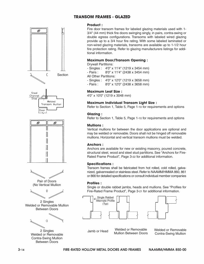
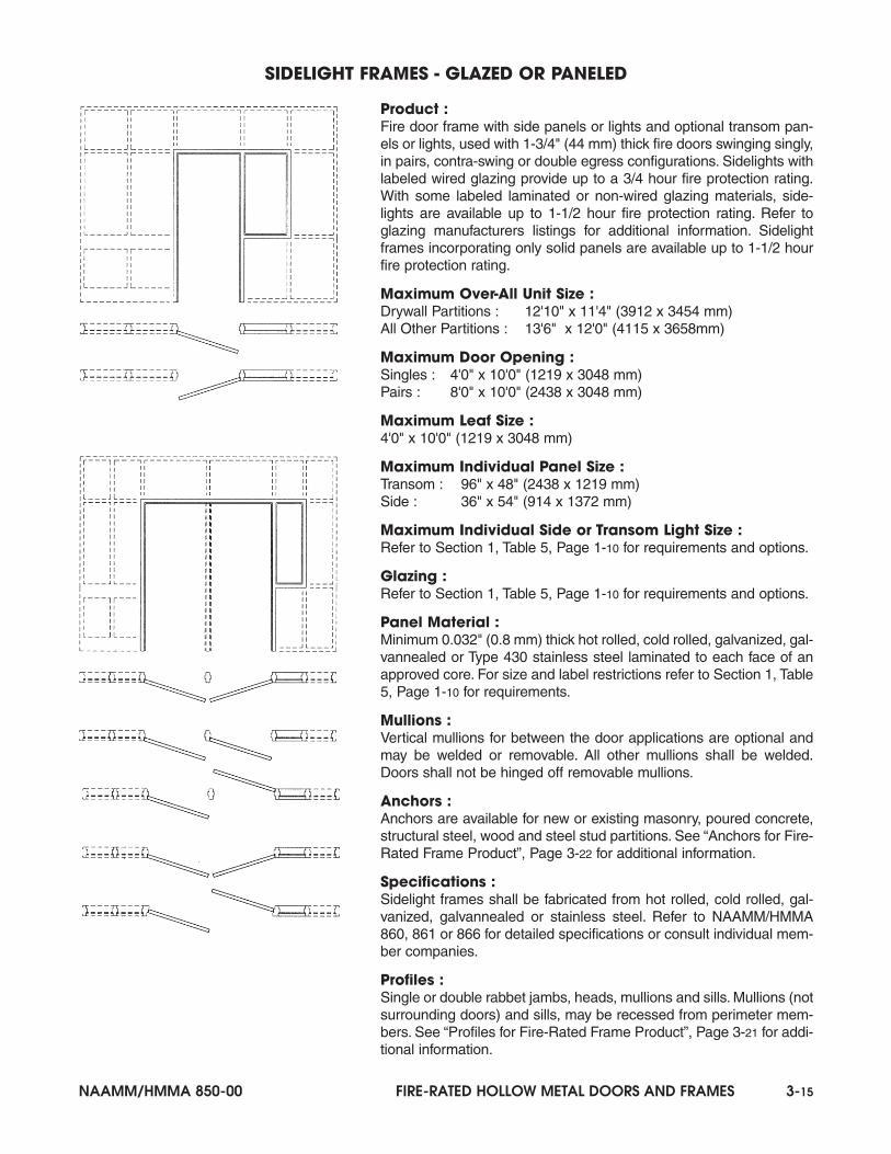
Product :Fire door transom frames for labeled glazing materials used with 1-3/4" (44 mm) thick fire doors swinging singly, in pairs, contra-swing ordouble egress configurations. Transoms with labeled wired glazingprovide up to a 3/4 hour fire rating. With some labeled laminated ornon-wired glazing materials, transoms are available up to 1-1/2 hourfire protection rating. Refer to glazing manufacturers listings for addi-tional information.
Maximum Door/Transom Opening :Drywall Partitions:- Singles : 4'0" x 11'4" (1219 x 3454 mm)- Pairs : 8'0" x 11'4" (2438 x 3454 mm)All Other Partitions:- Singles : 4'0" x 12'0" (1219 x 3658 mm)- Pairs : 8'0" x 12'0" (2438 x 3658 mm)
Maximum Leaf Size :4'0" x 10'0" (1219 x 3048 mm)
Maximum Individual Transom Light Size :Refer to Section 1, Table 5, Page 1-10 for requirements and options
Glazing :Refer to Section 1, Table 5, Page 1-10 for requirements and options
Mullions :Vertical mullions for between the door applications are optional andmay be welded or removable. Doors shall not be hinged off removablemullions. Horizontal and vertical transom mullions must be welded.
Anchors :Anchors are available for new or existing masonry, poured concrete,structural steel, wood and steel stud partitions. See “Anchors for Fire-Rated Frame Product”, Page 3-22 for additional information.
Specifications :Transom frames shall be fabricated from hot rolled, cold rolled, galva-nized, galvannealed or stainless steel.Refer to NAAMM/HMMA 860, 861or 866 for detailed specifications or consult individual member companies
Profiles :Single or double rabbet jambs, heads and mullions. See “Profiles forFire-Rated Frame Product”, Page 3-21 for additional information.
TRANSOM FRAMES - GLAZED
Jamb or Head Welded or RemovableMullion Between Doors
Welded or RemovableContra-Swing Mullion
Pair of Doors(No Vertical Mullion
2 SinglesWelded or Removable Mullion
Between Doors
2 SinglesWelded or RemovableContra-Swing Mullion
Between Doors
Single RabbetAlternate Profile
(Typ)
Section
NAAMM/HMMA 850-00 FIRE-RATED HOLLOW METAL DOORS AND FRAMES 3-15
Product :Fire door frame with side panels or lights and optional transom pan-els or lights, used with 1-3/4" (44 mm) thick fire doors swinging singly,in pairs, contra-swing or double egress configurations. Sidelights withlabeled wired glazing provide up to a 3/4 hour fire protection rating.With some labeled laminated or non-wired glazing materials, side-lights are available up to 1-1/2 hour fire protection rating. Refer toglazing manufacturers listings for additional information. Sidelightframes incorporating only solid panels are available up to 1-1/2 hourfire protection rating.
Maximum Over-All Unit Size :Drywall Partitions : 12'10" x 11'4" (3912 x 3454 mm)All Other Partitions : 13'6" x 12'0" (4115 x 3658mm)
Maximum Door Opening :Singles : 4'0" x 10'0" (1219 x 3048 mm)Pairs : 8'0" x 10'0" (2438 x 3048 mm)
Maximum Leaf Size :4'0" x 10'0" (1219 x 3048 mm)
Maximum Individual Panel Size :Transom : 96" x 48" (2438 x 1219 mm)Side : 36" x 54" (914 x 1372 mm)
Maximum Individual Side or Transom Light Size :Refer to Section 1, Table 5, Page 1-10 for requirements and options.
Glazing :Refer to Section 1, Table 5, Page 1-10 for requirements and options.
Panel Material :Minimum 0.032" (0.8 mm) thick hot rolled, cold rolled, galvanized, gal-vannealed or Type 430 stainless steel laminated to each face of anapproved core. For size and label restrictions refer to Section 1, Table5, Page 1-10 for requirements.
Mullions :Vertical mullions for between the door applications are optional andmay be welded or removable. All other mullions shall be welded.Doors shall not be hinged off removable mullions.
Anchors :Anchors are available for new or existing masonry, poured concrete,structural steel, wood and steel stud partitions. See “Anchors for Fire-Rated Frame Product”, Page 3-22 for additional information.
Specifications :Sidelight frames shall be fabricated from hot rolled, cold rolled, gal-vanized, galvannealed or stainless steel. Refer to NAAMM/HMMA860, 861 or 866 for detailed specifications or consult individual mem-ber companies.
Profiles :Single or double rabbet jambs, heads, mullions and sills. Mullions (notsurrounding doors) and sills, may be recessed from perimeter mem-bers. See “Profiles for Fire-Rated Frame Product”, Page 3-21 for addi-tional information.
SIDELIGHT FRAMES - GLAZED OR PANELED
3-16 FIRE-RATED HOLLOW METAL DOORS AND FRAMES NAAMM/HMMA 850-00
Product :Fire window frames with fixed openings and labeled glazing materialsor panels. Windows with labeled wired glazing provide up to a 3/4hour fire protection rating. With some labeled laminated and non-wired glazing materials, windows are available up to 1-1/2 hour fireprotection rating. Refer to glazing manufacturers listings for addition-al information. Fire windows may be mounted directly on the floor oron knee wall partitions.
Maximum Over-All Unit Size :Drywall Partitions : 12'10" x 11'4" (3912 x 3454 mm)All Other Partitions : 13'6" x 12'0" (4115 x 3658 mm)
Maximum Individual Light Size :Refer to Section 1, Table 5, Page 1-10 for requirements and options
Glazing : Refer to Section 1, Table 5, Page 1-10 for requirements and options
Panel Material :Minimum 0.032" (0.8 mm) thick hot rolled, cold rolled, galvanized, gal-vannealed or Type 430 stainless steel laminated to each face of anapproved core. For size and label restrictions refer to Section 1, Table5, Page 1-10 for requirements.
Anchors :Anchors are available for new or existing masonry, poured concrete,structural steel, wood and steel stud partitions. See “Anchors for Fire-Rated Frame Product”, Page 3-22 for additional information.
Specifications :Window frames shall be fabricated from hot rolled, cold rolled, galva-nized, galvannealed or stainless steel. Refer to NAAMM/HMMA 860,861 or 866 for detailed specifications or consult individual membercompanies.
Profiles :Single or double rabbet jambs, heads, mullions and sills. Mullions andsills may be recessed from perimeter members. See “Profiles for Fire-Rated Frame Product”, Page 3-21 for additional information.
WINDOW FRAMES - GLAZED OR PANELED
Jamb or Head Mullions Sill
Single RabbetAlternate Profile
(Typ)
Knee Wall Mounted Fire Window
Floor Mounted Fire Window
NAAMM/HMMA 850-00 FIRE-RATED HOLLOW METAL DOORS AND FRAMES 3-17
Product :3 hour (maximum) sound control fire door and frameassembly with 1-3/4" (44 mm) (minimum) thick doors,swinging singly or in pairs. Doors, frame and soundseals must be provided as a complete assembly.
Maximum Door Opening :Singles : 4'0" x 8'0" (1219 x 2438 mm)Pairs : 8'0" x 8'0" (2438 x 2438 mm)
Maximum Leaf Size :4'0" x 8'0" (1219 x 2438 mm)
Glazing :3 hour - glazing not permitted (STC* 52 maximum)11/2 hour - 100 in2 (0.065m2) glass light per leaf
* : STC - Sound Transmission Class : Air borne soundtransmission loss is measured in accordance withASTM E90 and the STC is determined by the proce-dures set forth in ASTM E413
Mullions :Welded mullions for between the door applications areoptional.
Anchors :Anchors are available for new or existing masonry,poured concrete, structural steel, wood and steel studpartitions. See “Anchors for Fire-Rated FrameProduct”, Page 3-22 for additional information.
Specifications :Assemblies shall be fabricated from hot rolled, coldrolled, galvanized or galvannealed steel. Refer toNAAMM/HMMA 865 for detailed specifications or con-sult individual member companies.
Profiles :Cased open, single or double rabbet jambs, heads andmullions with applied adjustable gasketing.
SOUND CONTROL HOLLOW METAL DOOR AND FRAME ASSEMBLIES
Jamb or Head(Gasket varies
with manufacturer)
Pair of Doors(No Vertical Mullion)
2 SinglesWelded MullionBetween Doors
Door Bottom Details(Varies with manufacturer)
Single RabbetAlternate Profile
(Typ)
AdjustableGasket
3-18 FIRE-RATED HOLLOW METAL DOORS AND FRAMES NAAMM/HMMA 850-00
Product :3 hour (maximum) detention security fire door andframe assembly swinging singly or in pairs or slidingsingly, for use in detention and correctional facilitiesand other buildings where a high degree of security isrequired. Detention security assemblies must complywith ASTM F1450 test procedures and acceptance cri-teria of HMMA 863 for impact resistance, static load,rack, edge crush and removable glazing stop require-ments. In addition these products are available withbullet-resistant capabilities meeting ANSI/UL 752.
Maximum Door Opening :Singles : 4'0" x 8'0" (1219 x 2438 mm)Pairs : 8'0" x 8'0" (2438x 2438 mm)Sliding : 4'0" x 8'0" (1219 x 2438 mm)
Maximum Leaf Size :4'0" x 8'0" (1219 x 2438 mm)
Glazing :Refer to Section 1, Table 4, Page 1-9 for door require-ments and options
Mullions :Welded mullions for between the door applications areoptional.
Anchors :Anchors are available for new or existing masonry orpoured concrete partitions. See “Anchors for Fire-Rated Frame Product”, Page 3-22 for additional information
Specifications :Assemblies shall be fabricated from hot rolled, coldrolled, galvanized or galvannealed steel. Refer toNAAMM/HMMA 863 for detailed specifications or con-sult individual member companies.
Profiles :Single and double rabbet jambs, heads and mullions.See “Profiles for Fire-Rated Frame Product”, Page3-21 for additional information.
DETENTION SECURITY HOLLOW METAL DOOR AND FRAME ASSEMBLIES
SingleDoor Mounted Lock
SingleJamb Mounted Lock
Single RabbetAlternate Profile
(Typ)
Pair of Doors(No Mullion)
Door Mounted Lock
2 SinglesWelded Mullion Between Doors
Door Mounted Lock
Door Mounted LockStrike Jamb, Hinge
Jamb Head
Welded MullionBetween Doors
Jamb Mounted LockStrike Jamb
NAAMM/HMMA 850-00 FIRE-RATED HOLLOW METAL DOORS AND FRAMES 3-19
Product :3 hour (maximum) bullet-resistant fire door and frameassembly swinging singly or in pairs, intended to formbullet-resistant barriers which protect against robberyor holdup.
These are specialized door and frame assemblies pro-viding protection from medium (9 mm) through superpower (.44 Magnum) hand guns, high power (30-06)rifles, military munitions (308 Winchester rifle) or multi-ple shots from submachine guns (9mm Uzi) up to mil-itary assault rifles (M-14). These assemblies havebeen tested to the requirements of ANSI/UL 752,“Bullet-Resisting Equipment”.
There are 8 rating levels with Level 1 for mediumpower hand guns up to Level 8 for M-14 assault rifles.A supplementary category for 12 gage shot guns withrifled lead slug and 00 lead buckshot is also available.Assemblies meeting the additional shot gun require-ments have a suffix “SG” added to the rating designa-tion.
Maximum Door Opening :Singles : 4'0" x 10'0" (1219 x 3048 mm)Pairs : 8'0" x 10'0" (2438 x 3048 mm)
Maximum Leaf Size :4'0" x 10'0" (1219 x 3048 mm)
Glazing :Consult individual member companies for details
Mullions :Welded mullions for between the door applications areoptional
Anchors :Anchors are available for new or existing masonry,poured concrete, structural steel, wood and steel studpartitions. See “Anchors for Fire-Rated FrameProduct”, Page 3-22 for additional information.
Specifications :Assemblies shall be fabricated from hot rolled, coldrolled, galvanized or galvannealed steel. For all otherdesign and construction features consult individualmember companies.
Profiles :Single and double rabbet jambs, heads and mullions.See “Profiles for Fire-Rated Frame Product”, Page3-21 for additional information.
BULLET-RESISTANT HOLLOW METAL DOOR AND FRAME ASSEMBLIES
Single RabbetAlternate Profile
(Typ)
Pair of Doors(No Vertical Mullion)
2 SinglesWelded MullionBetween Doors
Jamb or Head Mullion
3-20 FIRE-RATED HOLLOW METAL DOORS AND FRAMES NAAMM/HMMA 850-00
Product :3 hour (maximum) radiation shielding door and frameassembly with 1-3/4" (44 mm) thick doors swingingsingly or in pairs used to provide shielding against x-rays and other forms of radiation which could be injuri-ous to humans, other forms of life or material.
These assemblies are designed to specification to pro-vide shielding against specific types and intensities ofradiation.
Maximum Door Opening :Singles : 4'0" x 8'0" (1219 x 2438 mm)Pairs : 8'0" x 8'0" (2438 x 2438 mm)
Maximum Leaf Size :4'0" x 8'0" (1219 x 2438 mm)
Glazing :Refer to Section 1, Table 4, Page 1-9 for requirements
Mullions :Welded mullions for between the door applications areoptional.
Anchors :Anchors are available for new or existing masonry,poured concrete, structural steel, wood and steel studpartitions. See “Anchors for Fire-Rated FrameProduct”, Page 3-22 for additional information
Specifications :Assemblies shall be fabricated from hot rolled, coldrolled, galvanized or galvannealed steel. For all otherdesign and construction features consult individualmember companies.
Profiles :Single or double rabbet jambs, heads and mullions.See “Profiles for Fire-Rated Frame Product”, Page3-21 for additional information.
RADIATION SHIELDING HOLLOW METAL DOOR AND FRAME ASSEMBLIES
Single RabbetAlternate Profile
(Typ)
Pair of Doors(No Vertical Mullion)
2 SinglesWelded MullionBetween Doors
Jamb or Head Mullion
Sheet LeadLining
NAAMM/HMMA 850-00 FIRE-RATED HOLLOW METAL DOORS AND FRAMES 3-21
Min 057.1 mm(3) 25.4 mm 4.8 mm 60.3 mm 15.9 mm 6.4 mm
13" 3/4" 12" 14-1/2" 3/4"Max - -
330.2 mm 19.1 mm 304.8 mm 368.3 mm 19.1 mm
Single Rabbet Jambs, Heads and Sills
A B C D E F G
Throat Return Face SoffitJamb
StopDrywall
Depth Return2"(3) 1" (2) 3/16" 2-1/8" 5/8" 1/4"
Min 050.8 mm(3) 25.4 mm 4.8 mm 60 mm 15.9 mm 6.4 mm
13" 3/4" 12" 14-1/2" 3/4"Max - -
330.2 mm 19.1 mm 304.8 mm 368.3 mm 19.1 mm
Single or Double Rabbet Mullions
C D E F
Face SoffitJamb
StopDepth
1" (2) 1" 4-1/2" 5/8"Min 0
25.4 mm 25.4 mm 114.3 mm 15.9 mm
12" 10-1/2"Max - -
304.8 mm 266.7 mm
(1) : To suit 1-3/4" (44 mm) doors(2) : For 3 sided frames in masonry or concrete partitions and surrounding glazed open-
ings in sidelight or window frames. 1-1/4" (31.8 mm) minimum at all frames in studwalls, all transom frames and surrounding door openings in sidelight frames.
(3) : Larger dimensions may be required to suit specific wall types
Wall Anchors - General :
PROFILES FOR FIRE-RATED FRAME PRODUCT
3-22 FIRE-RATED HOLLOW METAL DOORS AND FRAMES NAAMM/HMMA 850-00
Each jamb of the door frame shall be provided withanchors to fit the wall construction to which the jamb isto be fastened. Each anchor shall be located immedi-ately above or below the hinge reinforcing on the hingejamb and directly opposite on the strike jamb as shownin Figure 2. Fire-rated frames require two anchors foreach jamb up to 5'0" (1524 mm) and an additionalanchor for each additional 2'6" (762 mm) of height orfraction thereof.
For openings in stud partitions HMMA recommendsthat one additional anchor be provided for each jambover the number of anchors required for masonryopenings of equivalent height.
Approved anchors, similar to those shown on thesepages or non-welded, snap-in or friction fit as shown inHMMA 860, must be used with fire-rated frame prod-uct.
FIGURE 2SINGLE UNIT TYPE PRESSED STEEL FRAME
Masonry Anchors :
Figures 3A, 3B and 3C illustrate masonry anchorsapproved for fire-rated frames. The adjustable strap-and-stirrup type is recommended for hollow metalframes. The stirrup or “yoke” is welded to the back ofthe jamb soffit. This type of anchor can be used ineither masonry or poured concrete construction andprovides sufficient adjustment for masonry coursing aswell as access for full grouting of jambs.
FIGURE 3ASTRAP AND STIRRUP ANCHOR
FIGURE 3BT-STRAP ANCHOR
FIGURE 3CWIRE LOOP ANCHOR
ANCHORS FOR FIRE-RATED FRAME PRODUCT
NAAMM/HMMA 850-00 FIRE-RATED HOLLOW METAL DOORS AND FRAMES 3-23
Steel Stud Anchors :
Figure 4 illustrates a steel stud anchor which is weld-ed to the back of the jamb and attached to the steelstud by welding or mechanical fasteners.
An alternate anchorage method, similar to that shownin Figure 6, where jamb and head soffits are piercedand dimpled for 1/4" (6mm) diameter sheet metalscrews not more than 6" (152 mm) from each end andat 24" (610 mm) OC maximum, is also permitted.
FIGURE 4STEEL STUD ANCHORS
Wood Stud Anchors :
Figures 5A and 5B illustrate wood stud anchors whichare welded to the back of the jamb and attached to thewood studs with fasteners through holes in the anchor.
The anchor method illustrated in Figure 6 can also beused for wood stud partitions. Wood screws replacethe sheet metal screws.
FIGURE 5A FIGURE 5B WOOD STUD WOOD STUD
ANCHORZ ANCHOR
Expansion-Shell Anchors :
Figure 6 illustrates an existing masonry or concreteanchor. The frame is anchored in prepared openingsby means of flat head bolts and expansion shells.Anchors of this type are located not more than 6 inch-es (152 mm) from the top and bottom of each jambwith intermediate anchors spaced at a maximum of 26inches (660 mm) on center.
FIGURE 6EXPANSION BOLT ANCHOR
Floor Anchors :
Figure 7A illustrates a welded floor anchor and Figure7B shows an adjustable type floor anchor. Theseanchors must be welded to the inside face of eachframe. Floor anchors are not required for two-sectiontype frames with a pressed-steel rough buck, nor arethey required for frames provided with expansion-shellanchors.
FIGURE 7A FIGURE 7BWELDED FLOOR ADJUSTABLE
ANCHOR FLOOR ANCHOR
3-24 FIRE-RATED HOLLOW METAL DOORS AND FRAMES NAAMM/HMMA 850-00
4' x 9' • • • • • • • •4' x 10' • • • • • • •
2 @ 4' x 10' • • • • • •2 @ 4' x 10' • • • • • •
8' x 10' • • • • • • • •8' x 10' • • • • • • •8' x 10' • • • • • • • • •8' x 10' • • • • • • •8' x 10' • • • • • • •8' x 10' • • • • • • • • •4' x 8' • • • • • • •4' x 10' • • • • • • •8' x 10' • • • • • • • •8' x 10' • • • • • • • •8' x 10' • • • • • • •8' x 10' • • • • • • •8' x 10' • • • • • • •3'4 x 8' • • • • •4' x 8' • • • • •8' x 8' • • • • • •8' x 8' • • • • • •8' x 8' • • • • •4' x 8' • • • • • • •4' x 10' • • • • •8' x 10' • • • • • • •4' x 8' • • • • •8' x 8' • • • • • • •4' x 8' • • • • •8' x 8' • • • • • • •4' x 10' • • • • •8' x 10' • • • • • • •4' x 8' • • • • • • • •8' x 8' • • • • • • • • •8' x 8' • • • • • • • •
SUMMARY – HOLLOW METAL FIRE DOORS
Doo
r D
escr
iptio
n
Max
imum
Fire
Rat
ing
(Hou
rs)(1
)
Max
imum
Doo
r O
peni
ng
Sw
ingi
ng S
ingl
y
Sw
ingi
ng in
Pai
rs
0.09
3" (
2.3
mm
, 12
ga)
0.06
7" (
1.7
mm
, 14
ga)
0.05
3" (
1.3
mm
, 16
ga)
0.04
2" (
1.0
mm
, 18
ga)
Lock
or
Latc
h(2)
Mor
tise
Fire
Exi
t Har
dwar
e
Rim
Fire
Exi
t Har
dwar
e(3)
Vert
ical
Rod
Fire
Exi
t Har
dwar
e
Lock
or
Latc
h(2)
Mor
tise
Fire
Exi
t Har
dwar
e(4)
Rim
Fire
Exi
t Har
dwar
e(3)
Vert
ical
Rod
Fire
Exi
t Har
dwar
e
Ope
n B
ack
Str
ike
Flu
sh B
olts
With
Ove
r-La
ppin
g A
stra
gal
With
out O
ver-
Lapp
ing
Ast
raga
l
Single Door or Inactive Leaf of Pair orFace Sheets
Active Leaf of Pair 2nd Leaf of 2 Singles
Basic Fire Door(6,7)
Pairs in aMeans of Egress(6,7)
Temperature RiseRated Door(7)
(250°F at 30Minutes Maximum)
Double Egress Door(6,7)
Stainless Steel Door(Type 304 or 316)
Dutch Door
Louvered Door(7)
Sound Control Door(STC 52 Maximum)
Detention SecurityDoor(6)
Bullet-Resistant Door
Radiation ShieldingDoor
(1) : Plus all lower ratings (2) : 1/2" latch throw for singles to 8'0" height, 3/4" for singles over 8'0" height and all pairs(3) : Requires mullion behind doors (4) : Requires mullion between doors (5) : Requires co-ordinator and carry bar (6) : Tested to Negative Pressure (UL10b and ANSI/NFPA 252) and Positive Pressure (ANSI/UL10c, UBC 7-2 1997 and ISO 3008)(7) : Includes hot rolled, cold rolled, galvanized, galvanneal and Type 430 stainless steel
3
11/2
3(5)
11/2
3
11/2
311/2
3
11/2
3
11/2
3
3
3
3
NAAMM/HMMA 850-00 FIRE-RATED HOLLOW METAL DOORS AND FRAMES 3-25
Three-Sided Frame(5)
Double Egress(5)
Multi-Opening Framesor Transom Frames(5)
Transom Framewith 13/4" Panel
No Transom Mullion(5)
Transom Framewith 13/4" Panel
and Transom Mullion(5)
Transom Framewith Panel
and Transom Mullion(5)
Transom FrameGlazed(5)
Sidelight FrameGlazed or Paneled(5)
Window FrameGlazed or Paneled(5)
Sound Control Frame(STC 52 Maximum)
DetentionSecurity Frame(5)
Bullet-ResistantFrame
RadiationShielding Frame
SUMMARY – FIRE DOOR FRAME PRODUCT
Fram
e D
escr
iptio
n
Max
imum
Rat
ing
(Hou
rs)(1
)
Sw
ingi
ng S
ingl
y
Sw
ingi
ng in
Pai
rs
Max
imum
Doo
r O
peni
ng
Max
imum
Indi
vidu
alTr
anso
m P
anel
Siz
e
0.09
3" (
2.3
mm
, 12
ga)
0.06
7" (
1.7
mm
, 14
ga)
0.05
3" (
1.3
mm
, 16
ga)
Mild
Ste
el(2
)
Type
430
Sta
inle
ss S
teel
Type
304
/316
Sta
inle
ss S
teel
Mas
onry
Con
cret
e
Woo
d/S
teel
Stu
d
Max
imum
Ove
r-A
llU
nit S
ize
Thickness Material Anchors
• 4' x 10'3 - • • • • • • • • •• 8' x 10'
3 • 8' x 10' - • • • • • • • • •
• 4' x 10' 12'8" x 8'0" Frames11/2 8' x 4' • • • • • • • • •• 8' x 10' 12'8" x 10' Transom Frames
• 4' x 9' 4' x 4'6" 11'10"(3) Height3 • • • • • • • • •
• 8' x 9' 8' x 4' 11'2"(3) Height
• 4' x 10' 4' x 4'3 • • • • • • • • • 11'10"(3) Height
• 8' x 10' 8' x 4'
• 4' x 10' 4' x 4'3 • • • • • • • • • 12'(3) Height
• 8' x 10' 8' x 4'
• • 12'(3) Height
• 4' x 10' - • 11'4"(3) Height11/2
(4) • • • • • • • • 12'(3) Height
• 8' x 10' - • 11'4"(3) Height
• • 13'6" x 12'
• 4' x 10' • 12'10" x 11'4"11/2
(4) 8' x 4' • • • • • • • 13'6" x 12'
• 8' x 10' • 12'10" x 11'4"
• • 13'6" x 12'11/2
(4) - - - - • • • • • • 12'10" x 11'4"
• 4' x 8'3
• 8' x 8'- • • • • • • • •
• 4' x 8'3
• 8' x 8'- • • • • • •
• 4' x 10'3
• 8' x 10'- • • • • • • • •
• 4' x 8'3
• 8' x 8'- • • • • • • • •
(1) : Plus all lower ratings(2) : Includes hot rolled, cold rolled, galvanized and galvanneal steel(3) : Combined door and transom panel height(4) : With listed laminated or solid ceramic glazing materials. Refer to Section 1, Table 5, Page 1-10 for other available glazing materials and their ratings(5) : Tested to Negative Pressure (UL10b and ANSI/NFPA 252) and Positive Pressure (ANSI/UL10c, UBC 7-2 1997 and ISO 3008)
3-26 FIRE-RATED HOLLOW METAL DOORS AND FRAMES NAAMM/HMMA 850-00