MIT Lincoln Laboratory 999999-1 XYZ 10/13/2010 Holographic Optical Beam-Steering Demonstration Group 66 – Advanced Lasercom Systems and Operations MQP Final Presentation Gabriel Ayers Michael Ciampa Nicholas Vranos 13 October 2010 This work was sponsored by the Department of the Air Force under Air Force Contract FA8721-05-C-0002. Opinions, interpretations, conclusions, and recommendations are those of the author and are not necessarily endorsed by the United States Government.
Transcript
MIT Lincoln Laboratory999999-1
XYZ 10/13/2010
Holographic Optical Beam-Steering
Demonstration
Group 66 – Advanced Lasercom Systems and Operations
MQP Final Presentation
Gabriel Ayers
Michael Ciampa
Nicholas Vranos
13 October 2010
This work was sponsored by the Department of the Air Force under Air Force Contract FA8721-05-C-0002. Opinions, interpretations,
conclusions, and recommendations are those of the author and are not necessarily endorsed by the United States Government.
MIT Lincoln Laboratory999999-2
XYZ 10/13/2010
Presentation Outline
• Optical Beam-Steering Background
• Project Goals
• System Design
• Characterization of holographic gratings
• Pointing and Beam-Steering measurements
• Conclusions and Future Work
MIT Lincoln Laboratory999999-3
XYZ 10/13/2010
Beam Steering Applications
• Free-space laser communications ("lasercom")
– High Bandwidth
– High Security
– Point to Point laser communication
• Infrared Countermeasures
– Possibly used to ‘blind’ sensors of airborne projectiles
• Laser Radar
MIT Lincoln Laboratory999999-4
XYZ 10/13/2010
Beam Steering Examples
Gimbaled Mirrors Risley Prisms
BAE Systems Agile Eye
Infrared Countermeasure
Optra 2” diameter clear
aperture compact beam
steering system
MIT Lincoln Laboratory999999-5
XYZ 10/13/2010
• Conformal intrudes less into an aircraft’s air stream
– Less impact to flight dynamics
– Less drag induced to aircraft
– Less optical distortions to beam
Conformal vs. Nonconformal Beam Directors
BeamDirector
Optical module
Window Interface
Beam Director
Optical module
Turret Interface
MIT Lincoln Laboratory999999-6
XYZ 10/13/2010
Holographic Optical Diffraction Gratings
What is a Holographic Optical Diffraction Grating?
In each optical element there is a periodic structure, which modulates the refractive index. This structure uses Bragg diffraction to deflect the beam.
Properties:
• Reflection or Transmission mode
• Multi-Wavelength
• High Efficiency
• High Power
• Thermally Stable
HOBS Gratings:
• Square 50 mm
• Blazed for two wavelengths
• Transmission Mode
MIT Lincoln Laboratory999999-7
XYZ 10/13/2010
Single Degree of Freedom
• Gratings diffract light at constant angle
• Steer laser beam by rotating gratings around the optical axis
MIT Lincoln Laboratory999999-8
XYZ 10/13/2010
Two Degrees of Freedom
• Second diffraction grating and motor pair is positioned normal to the diffracted beam of the first grating
• Steering range is dependent on diffraction angle
MIT Lincoln Laboratory999999-9
XYZ 10/13/2010
HOBS Goal
• Construct a Holographic Optical Beam-Steering
(HOBS) prototype capable of steering two
wavelengths to transmit and receive
• Develop a steering algorithm
• Characterize the optical properties of the system
• Deliver a prototype demonstration and evaluation
to Lincoln Laboratory
MIT Lincoln Laboratory999999-10
XYZ 10/13/2010
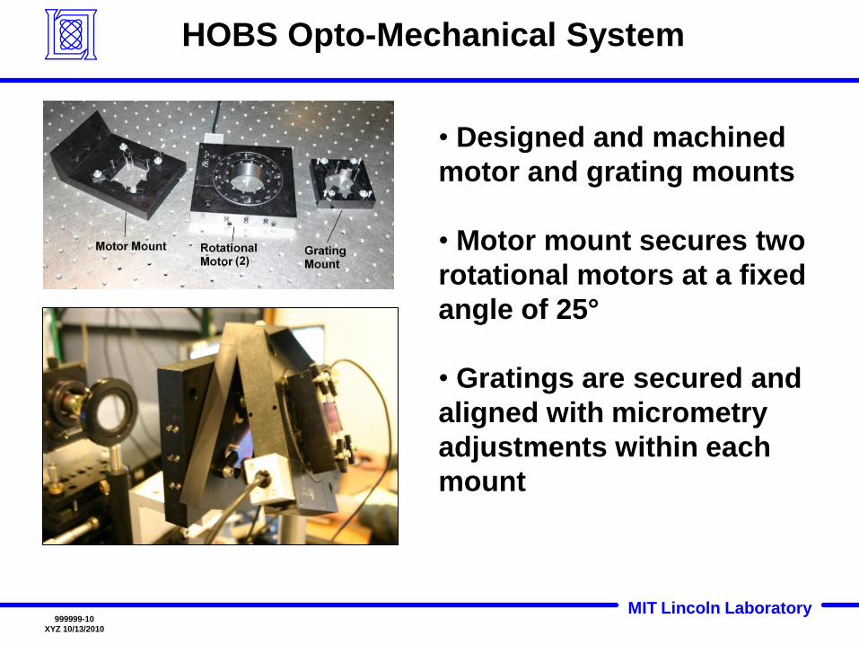
HOBS Opto-Mechanical System
• Designed and machined
motor and grating mounts
• Motor mount secures two
rotational motors at a fixed
angle of 25°
• Gratings are secured and
aligned with micrometry
adjustments within each
mount
MIT Lincoln Laboratory999999-11
XYZ 10/13/2010
Holographic Optical Beam-Steering: Concept
and Realization
• Simulation verifies beam-steering closed form solution using
numerical analysis
• Realization of the system shows ballistic trajectory using closed


![A compact holographic projector module for high-resolution ... · Simultaneous steering of multiple laser beams via holographic projection offers a solution [14–22]. High optical](https://static.documents.pub/doc/80x56/5eaa53847a62895ac50a3bf9/a-compact-holographic-projector-module-for-high-resolution-simultaneous-steering.jpg)


