66
CERAMIC CAPACITOR CATALOG Holy Stone Enterprise Co., Ltd. www.holystone.com.tw www.holystonecaps.com

CERAMIC CAPACITOR
CATALOG
Holy StoneEnterprise Co., Ltd.
www.holystone.com.twwww.holystonecaps.com

Introduction
The Company Holy Stone Enterprise
Company Ltd. (Holy Stone) was established
in June of 1981 as an agent and distributor of electronic components.
In 1994, with technologyand cooperation from a Japanese partner, Holy
Stone began manufacturing Multi-layer Ceramic Capacitors. Today, Holy Stone is recognized as an industry leader in application specific ceramic
capacitors.
Holy Stone integrates active and passive component distribution with significant
manufacturing capabilities. Holy Stone’s unique business model combines the service and inventory management strengths of a broad line
distributor with the technical knowledge and world class pricing of a manufacturer.
Holy Stone was founded by five engineers in 1981. Since this point Holy Stone has maintained a
focus and commitment to providing customers with innovative products and exceptional service.
The result of that unwavering commitment is evident in Holy Stone’s phenomenal growth. Holy
Stone also maintains a high profile on the Taiwan Stock Exchange, ranked in the top 100 companies and the leader among its peers.
Manufacturing FacilitiesHoly Stone capacitors are produced in two modern
factories located in Lungtanand Yilan, Taiwan.
In addition to these factories, the advanced materials research laboratory is located in Japan.The factory operating systems are certified to
ISO-9001 and ISO-14001.
Sales and Support Locations
Holy Stone administrativeHeadquarters are located
in Taipei, Taiwan.Holy Stone maintains sales and support offices
in Kaohsiung, Taiwan, Shenzhen, Suzhou and
Shanghai, China.
Holy Stone Enterprise Company Ltd has
subsidiary companies in North America and in Europe. ” HolyStone International”, located in
Murrieta, California, U.S.A. is responsible for sales and technical support in the Americas.
“HolyStone (Europe) Ltd.”, located in Norwich, England is responsible for sales and technical service for Europe. Holy Stone opened its
Singapore office to service Southeast Asia. Holy Stone also has a network of independent
representatives, Distributors and Agents throughout the world.
The Environment
Holy Stone is committed to the cause of achieving and maintaining a healthy environment. Holy
Stone is also among the first suppliers of halogen free epoxy coated capacitors. The factory is Certified to ISO-14000 and all standard products
are designed and produced conforming to full RoHS compliance.
Our Employees
Holy Stone’s success is measured by the satisfaction of our customers and share holders.
Achieving that satisfaction is the result of the sum contribution of our employees. Those
contributions come from all of our employees, whether they are engaged in administrative functions, manufacturing our goods or servicing
our customers. Holy Stone strives to maintain a work environment that stimulates creativity,
encourages enthusiasm and rewards results.
You should know Holy Stone.

Contents
Holy Stone
- 1 -
Component Quick Reference ------------------------------------------ 2
Capacitance Availability Guide ----------------------------------------- 3-4
Products Series ----------------------------------------------------------- 5-47
Packing Information ------------------------------------------------------ 48-51
General Information ------------------------------------------------------- 52-53
Precautionary Information ---------------------------------------------- 54-57
Reducing Short Circuit Risks – Super Term ----------------------- 58-59
Coated Products for Surface Arc Prevention --------------------- 60-61
RoHS Compliant ----------------------------------------------------------- 62
ISO Certifications ---------------------------------------------------------- 63
CONTENTS

Component Quick Reference
Holy Stone
- 2-
Product Series Application Page
HVC Series --High Voltage Capacitors
For Power Circuits(Backlight Inverter, DC to DC,…) 5-8
SCC Series --Safety Capacitors
For Isolation and Protection Circuits (UL, EN132400 Class X2/Y3, X1/Y2, and X2) 9-10
TCX Series --Trigger Capacitors For DSC Strobe Circuits 11-12
LDC Series --Low Distortion Capacitors For Oscillation and Filter Circuits 13-14
NCC Series --Normal Chip Capacitors For Decoupling Circuits 15-16
HCC Series --High Capacitance MLCC-More than 1uF For Smoothing (DC to DC) and Decoupling Circuits 17-18
HCN Series --Hi-Cap NP0
For ADSL/xDSL(Replacement for Film Capacitor) 19-20
HCX Series --Hi-Cap X7R
For Input, Output Filters (DC to DC) 21-22
SAC Series --Tip & Ring Capacitors For Telephone Line Ringer Circuits 23-24
HBC Series –Low-Loss High Frequency Capacitors For Hi-Frequency Pulse & Lighting Ballast Snubber Circuits 25-26
HTC Series --X8R Rated up to +150°C For High Temperature Applications 27-28
RFC Series --Radio Frequency Capacitors
For High Q & High Frequency Circuits(For Matching Resonant and Coupling Circuit) 29-31
LCC Series --Large Size MLCC (1515 to 7565)
For Voltage Multipliers, Power Circuit (DC-DC, Ballast,
Snubbe), Surge protection, Industrial Control, …32-33
RDC Series --Radial Dipped Ceramic Capacitors For Car Electronic, Inverter and Converter, Power Supplier 34-35
HDC Series --High Voltage Ceramic Disc Capacitors
For xDSL, Power Circuits(Backlight Inverter, Power Supplier, …) 36-37
HDC Series --Low Loss/Low DF Ceramic Capacitors
For 1KV to 3KV Application(Power Supplier, Adaptor, …) 38-39
HDC Series --Ultra High Voltage Ceramic Capacitors
For 10KV to 20KV Application(Pump, Hybrid Engine, Power Supplier, …) 40-43
SDC Series --Safety Ceramic Disc Capacitors
For xDSL, Set Top Box, VOIP, Power Supplier(UL, CSA, EN132400 Class X1/Y2, X1/Y1) 44-47

Capacitance Availability Guide – Standard MLCC
- 3 -
Vdc 0201 0402 0603 0805 1206 1210 1808 1812 1825 2220 2225
6.3V
NP0
X7R 100nF 2.2uF 10uF 22uF
X5R 470nF 10uF 22uF 47uF 100uF 100uF
10V
NP0
X7R 100nF 2.2uF 10uF 22uF 22uF
X5R 4.7uF 10uF 22uF 47uF 47uF
16V
NP0 100pF 3.3nF 10nF 27nF 47nF 120nF
X7R 3.9nF 100nF 1uF 10uF 10uF 22uF
X5R 1uF 4.7uF 22uF 22uF 47uF
25V
NP0 100pF 470pF 3.3nF 10nF 10nF 22nF 120nF
X7R 2.2nF 47nF 1uF 4.7uF 10uF 22uF 10uF
X5R 1uF 2.2uF 22uF 22uF 22uF
35V
NP0
X7R 2.2uF 4.7uF 10uF 4.7uF
X5R
50V
NP0 470pF 3.3nF 10nF 33nF 47nF 100nF 82nF
X7R 100nF 2.2uF 4.7uF 10uF 4.7uF 4.7uF 10uF 10uF
X5R 1uF 2.2uF 4.7uF 10uF
100V
NP0 680pF 3.9nF 12nF 10nF 100nF 56nF 56nF 68nF
X7R 22nF 100nF 1uF 2.2uF 2.2uF 2.2uF 4.7uF 4.7uF
X5R
200V
NP0 680pF 1.2nF 5.6nF 10nF 18nF 47nF 47nF 56nF
X7R 47nF 100nF 470nF 1uF 1uF 2.2uF 2.2uF
X5R
250V
NP0 680pF 1.2nF 5.6nF 10nF 18nF 47nF 47nF 56nF
X7R 47nF 100nF 470nF 1uF 1uF 2.2uF 2.2uF
X5R
500V
NP0 680pF 5.6nF 6.8nF 2.2nF 8.2nF 47nF 39nF 47nF
X7R 22nF 68nF 100nF 47nF 220nF 270nF 470nF 470nF
X5R
630V
NP0 2.2nF 6.8nF 1.8nF 8.2nF 27nF 27nF 33nF
X7R 33nF
X5R
1KV
NP0 1nF 2.2nF 1.2nF 6.8nF 12nF 12nF 15nF
X7R 1nF 10nF 27nF 15nF 68nF 100nF 100nF 100nF
X5R
2KV
NP0 390pF 1nF 1.5nF
X7R 1.8nF 2.7nF 3.3nF 10nF 18nF 18nF 18nF
X5R
3KV
NP0 39pF 1nF 1.2nF
X7R 1.8nF 2.7nF
X5R
4KV
NP0
X7R 1nF
X5R
5KV
NP0 27pF 120pF
X7R
X5R
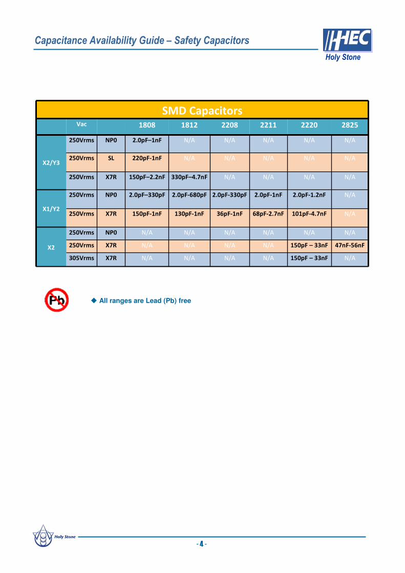
Capacitance Availability Guide – Safety Capacitors
Holy Stone
47nF-56nF150pF – 33nFN/AN/AN/AN/AX7R250Vrms
N/AN/AN/AN/AN/AN/ANP0250Vrms
X2
N/AN/AN/AN/AN/A220pF-1nFSL250Vrms
SMD CapacitorsVac 1808 1812 2208 2211 2220 2825
X2/Y3
250Vrms NP0 2.0pF–1nF N/A N/A N/A N/A N/A
250Vrms X7R 150pF–2.2nF 330pF–4.7nF N/A N/A N/A N/A
X1/Y2
250Vrms NP0 2.0pF–330pF 2.0pF-680pF 2.0pF-330pF 2.0pF-1nF 2.0pF-1.2nF N/A
250Vrms X7R 150pF-1nF 130pF-1nF 36pF-1nF 68pF-2.7nF 101pF-4.7nF N/A
305Vrms X7R N/A N/A N/A N/A 150pF – 33nF N/A
All ranges are Lead (Pb) free
- 4 -

How To Order
Multilayer Ceramic Chip Capacitors
[ High Voltage NP0 and X7R Capacitors ]
HVC Series
Operation Temperature -55 ~ +125 Rated Voltage 100Vdc to 5000Vdc
Temperature Coefficient NP0 : ≤ ± 30ppm/ , -55 ~ +125 (EIA Class Ι )
X7R : ≤ ± 15% , -55 ~ +125 (EIA Class Ⅱ )
SL : ≤ +350/-1000 ppm/ , -25 ~ +85 (EIA Class Ι)
Dissipation Factor NP0/SL : Q≧1000 , X7R : D.F.≦2.5%
Insulation Resistance 10GΩ or 500/CΩ whichever is smaller
Aging NP0/SL : 0% , X7R : Typically 1.0% per decade of time
Dielectric Strength 100V ≦ V < 500V : 200% Rated Voltage
500V ≦ V < 1000V : 150% Rated Voltage
1000V≦ V : 120% Rated Voltage
Summary of Specifications
Special internal electrode design offers
the highest voltage rating
Surface mount suitable for wave and reflow
soldering
High reliability
RoHS compliant
Suitable for LAN/WLAN interface,
Back-Lighting Inverter, DC-DC Converters,
Ballast, Modems and Power Supplies.
Product CodeC: MLCC
(MultilayerCeramic Chip of Capacitor)
Chip Size
Ex.:
0603 0805 12061210 1808
181218252220 2225
Dielectric
Ex.:
N: NP0X: X7R
CapacitanceUnit : pFEx.:
2R0:2.0pF100:10×100
471:47×101
102:10×102
Tolerance
Ex.:
C:+/-0.25pFD:+/-0.50pFJ :+/- 5%K :+/-10%M:+/-20%
Rated
Voltage Ex.:101: 100Vdc251: 250Vdc
501: 500Vdc631: 630Vdc102: 1000Vdc202: 2000Vdc302: 3000Vdc
402: 4000Vdc502: 5000Vdc
Packaging
T: T/R 7”
R: T/R 13”B: Bulk
Thickness(mm)Ex:
B:0.85±0.10E:1.60±0.20
SpecialRequirement
Ex.:O: Arc
Prevention
Coating
X: Polymer
Termination
(Super Term)
HVC Series - High Voltage Capacitors
Holy Stone
Holy Stone high voltage products are designed and manufactured to meet the general requirements of
international standards. The product offering is well suitable for commercial and industrial applications and
includes NP0 (C0G), SL, and X7R characteristics in sizes 0603 to 2225 and with working voltages up to
5KV.
Applications Features
CC
- 5 -
12061206 XX 102102 KK 202202 TT EE XX

W
T
BW B
L
Dimensions
Capacitance Range – NP0 100Vdc to 1KVdc
TYPE L W T (max) B (min) BW (min)
0603 1.60±0.10[.063±.004]
0.80±0.10[.031 ±.004]
0.95[.037]
0.40[.016]
0.15[.006]
0805 2.00±0.20[.079±.012]
1.25±0.20[.049±.012]
1.45[.057]
0.70[.028]
0.20[.008]
1206 3.20±0.30[.126±.012]
1.60±0.20[.063±.012]
1.80[.071]
1.50[.059]
0.30[.012]
1210 3.20±0.30[.126±.012]
2.50±0.20[.098±.012]
2.60[.102]
1.60[.059]
0.30[.012]
1808 4.60±0.30[.181±.012]
2.00±0.20[.079±.008]
2.20[.087]
2.50[.098]
0.30[.012]
1812 4.60±0.30[.181±.012]
3.20±0.30[.126±.012]
3.00[.118]
2.50[.098]
0.30[.012]
1825 4.60±0.30[.181±.012]
6.35±0.40[.250±.016]
3.00 [.118]
2.50[.098]
0.30[.012]
2220 5.70±0.40[.220±.016]
5.00±0.40[.197±.016]
3.00 [.118]
3.50 [.137]
0.30[.012]
2225 5.70±0.40[.220±.016]
6.35±0.40[.250±.016]
3.00 [.118]
3.50 [.137]
0.30[.012]
Unit : mm [inches]
HVC Series - High Voltage Capacitors
Holy Stone
- 6 -
2R
03
R3
3R
95
R0
8R
21
00
12
01
50
18
02
20
27
03
30
39
04
70
56
06
80
82
01
01
12
11
51
18
12
21
27
13
31
39
14
71
56
16
81
82
11
02
12
21
52
18
22
22
27
23
32
39
24
72
56
26
82
82
21
03
12
31
53
18
32
23
27
33
33
39
34
73
56
36
83
10
4
B B B B B B B B B B B B B B
B B B B B B B B B B B B B B B B B B B B B B B B B B B B
B B B B B B B B B B B B B B B B B B B B B B B B B B B B
B B B B B B B B B B B B B B B B B B B B B B B B B B B B
B B B B B B B B B B B B B B B B B B B B B B B B B B B B/CB/CB/CB/D B B C/D D D D
B B B B B B B B B B B B B B B B B B B B B B B B B B B B/CB/CB/CB/D
B B B B B B B B B B B B B B B B B B B B B B B B B B B B/CB/CB/CB/D
C C C C C C C C C C C C C C C C C C C C C C C C C C C
B/CB/CB/CB/CB/CB/CB/CB/CB/CB/CB/CB/CB/CB/CB/CB/CB/CB/CB/CB/CB/CB/CB/CB/CB/CB/CB/CB/CB/CB/CB/CB/CB/CB/CB/CB/CB/CB/C D D D D E
B/CB/CB/CB/CB/CB/CB/CB/CB/CB/CB/CB/CB/CB/CB/CB/CB/CB/CB/CB/CB/CB/CB/CB/CB/CB/CB/DB/DB/DD/E D/E D/E D/ED/E D/E D/E D/E D/E E
B/CB/CB/CB/CB/CB/CB/CB/CB/CB/CB/CB/CB/CB/CB/CB/CB/CB/CB/DB/DB/DD/E D/E D/E D/ED/E D/E D/E D/E D/E E
B/CB/CB/CB/CB/CB/CB/CB/CB/CB/CB/CB/CB/CB/CB/CB/CB/CB/CB/DB/DB/DD/E D/E D/E D/ED/E D/E D/E D/E D/E E
C C C C C C C C C C C C C C C C C C D D DD/E D/E D/E D/ED/E
D D D D D D D D D D D D D D E E E E E E E E E E E
B/CB/CB/CB/CB/CB/CB/CB/CB/CB/CB/CB/CB/CB/CB/CB/CB/CB/CB/CB/CB/CB/CB/CB/C C D D D DD/ED/E D/E D/E D/E E E
C C C C C C C C C C C C C C C C C D D D DD/ED/E D/E D/E D/E E E
C C C C C C C C C C C C C C C C D D D E E F F
C C C C C C C C C C C C C C C C D D D E E F F
D D D D D D D DD/E D/E D/E D/E D/E D/E D/E D/E D/E D/E E
D D D D D D D D D D D D D D D D D D E E E E E E E E E E E E E E E E
D D D D D D D D D D D D D D D D D D E E E E E E E E E E E E F
D D D D D D D D D D D D D D D D D DD/ED/E D/E D/E D/E E E E
D D D D D D D D D D D D D D E E F F E/F E/F E/F F F/GF/GG
D D D D D D D D D D D E
D D D D D D D D D D D E E E E
D D D D D D D D D D DD/E E F
D E E E F F G G G1825
100V
200V
250V
500V
630V
1KV
1KV
2220
100V
200V
250V
500V
630V
1KV
1812
100V
1808
500V
630V
1KV
200V
250V
500V
630V
630V
1KV
1210
100V
200V
250V
500V
630V
1KV
1206500V
0805
100V
200V
250V
500V
Temperature
CharacteristicSize
Rated
Voltage
Capacitance Range
NP0
0603
50V
100V
200V
250V
100V
200V
250V

Capacitance Range – X7R 100Vdc to 1KVdc
HVC Series - High Voltage Capacitors
Holy Stone
- 7 -
Symbol Code S O A B C D E F G HThickness(mm) 0.3±0.03 0.5±0.05 0.6±0.1 0.85±0.1 1.0±0.1 1.25±0.20 1.6±0.2 2.0±0.2 2.4±0.2 2.8±0.2
Other dimensions, capacitance values and voltages ratings are available on request. Please contact Holy Stone.
Thickness Specifications
151
181
221
271
331
391
471
561
681
821
102
122
152
182
222
272
332
392
472
562
682
822
103
123
153
183
223
273
333
393
473
563
683
823
104
124
154
184
224
274
334
394
474
564
684
824
105
155
225
B B B B B B B B B B B B B B B B B B B B B B B B B B B
B B B B B B B B B B B B B B B B B B B B B B B B B B B B C
B/CB/CB/CB/CB/CB/CB/CB/CB/CB/CB/CB/CB/CB/CB/CB/CB/CB/CB/CB/CB/C D D D D
B/CB/CB/CB/CB/CB/CB/CB/CB/CB/CB/CB/CB/CB/CB/CB/CB/CB/CB/CB/CB/C D D D D
B/CB/CB/CB/CB/CB/CB/CB/CB/CB/CB/CB/C C C C C C C C C C
C C C C CB/CB/CB/CB/CB/CB/CB/C C C C C C C C C C
B/CB/CB/CB/CB/CB/CB/CB/CB/CB/CB/CB/CB/CB/CB/CB/CB/CB/CB/CB/CB/CB/CB/CB/CB/CB/CB/CB/CB/CB/CB/CB/CB/CB/CB/C C C C D E E E E E E E
B/CB/CB/CB/CB/CB/CB/CB/CB/CB/CB/CB/CB/CB/CB/CB/CB/CB/CB/CB/CB/CB/CB/CB/CB/CB/CB/CB/CB/CB/CC/DD/E D/E D/E
B/CB/CB/CB/CB/CB/CB/CB/CB/CB/CB/CB/CB/CB/CB/CB/CB/CB/CB/CB/CB/CB/CB/CB/CB/CB/CB/CB/CB/CB/CC/DD/E D/E D/E
C C C C C C C C C C C C C C C C C C C C C C C C C C C C C C D EV D D D D D D D D D D D D D D D D D D D D D D D D D E E
D D D D D D D D D D D D D D D D D D D D D
C C C C C C C C C C C C C C C C C C C C C D E E F G G
C C C C C C C C C C C C D D D D D E E E F
C C C C C C C C C C C C D D D D D E E E F
C D D D D D E E E F F F F
D D D D D E
D D D D D D D D D D D D D D D F
D D D D E E E F F F
D D D D D D D D D D D D D D D D D D D D D D D D D D D DD/E D/E D/E D/E D/E D/E D/E D/E D/E D/E D/E D/E E E E E E F F/G
D D D D D D D D D D D D D D D D D D D D D D D D D D D DD/E D/E D/E D/E D/E D/E D/E D/E D/E D/E D/E D/E E E E F G
D D D D D D D D D D D D D D D D D D D D D D D D D D D DD/E D/E D/E D/E D/E D/E D/E D/E D/E D/E D/E D/E E E E F G
D D D D D D D D D D D D D D D D D D D D D D D D D D D D E E E E E F F/G H H
D D D D D D D D D D D D D D D D D D E E E E E E F F/GF/GF/GF/GF/GF/GF/GG
D D D D D D D D D D D E E F H
D D D D D D D D D D D E E F H
E E E E E F G G H
E E E E E E E/F F F G G H H H H H H
D D D D D D D D D D D D D D D D D D D D E E E E E
D D D D D D D D D D D D D D D D D D D D E E E E E
D D D D D D D D D D D E E E
D D D E E F F F F F F F F
D D D D D D D D D D D D D D D D D E G
D D D D D D D D D D D D D D D D D E G
E E E E E E E E E F F F G
E E E E E
2225
200V
250V
500V
1KV
2220
200V
250V
500V
1KV
1825
200V
250V
500V
1KV
1808500V
1KV
1812
100V
200V
250V
500V
1KV
1210
100V
200V
250V
500V
1KV
1206
100V
200V
250V
500V
630V
1KV
Capacitance Range
X7R
0603 100V
0805
100V
200V
250V
500V
1KV
Temperature
CharacteristicSize
Rated
Voltage
2R
03
R3
3R
95
R0
8R
21
00
120
150
180
220
270
330
390
470
560
680
820
101
121
151
181
221
271
331
391
471
561
681
821
102
122
152
182
222
272
332
392
472
562
682
822
103
123
153
183
223
273
333
393
473
563
683
D D D
2225
100V
200V
250V
500V
630V
1KV
Temperature
CharacteristicSize
Rated
Voltage
Capacitance Range
NP0

HVC Series - High Voltage Capacitors
Holy Stone
- 8 -
Capacitance Range 2KV
Capacitance Range 3KVdc to 5KVdc
Symbol Code S O A B C D E F G HThickness(mm) 0.3±0.03 0.5±0.05 0.6±0.1 0.85±0.1 1.0±0.1 1.25±0.20 1.6±0.2 2.0±0.2 2.4±0.2 2.8±0.2
Thickness Specifications
Other dimensions, capacitance values and voltages rating are available on request. Please contact Holy Stone.
2R
0
3R
3
3R
9
5R
0
8R
2
100
120
150
180
220
270
330
390
470
560
680
820
101
121
151
181
221
271
331
391
471
561
681
821
102
122
152
182
222
272
D D D D D D D D D D D D D D D/E D/E D/E D/E D/E D/E
D D D D D D D D D D D D D D D D D D E/F E/F E/F E/F E/F E/F
D D D D D D D E E F F F F F F F F
Temperature
CharacteristicSize
Rated
Voltage
2KV
Capacitance Range
NP0
1206 2KV
1808 2KV
1812151
181
221
271
331
391
471
561
681
821
102
122
152
182
222
272
332
392
472
562
682
822
103
123
153
183
223
273
333
393
473
563
683
823
104
D D D D D D D D D/E E E E
D D D D D D D D D E E E F/G G
D D D D D D D D D D D D D D E F F
D D D D D D D D D D E E F F F F F F G H
E E E E F F F
D D D D D D E E F F F F F
E/F E/F
1825 2KV
2220 2KV
2225 2KV
Capacitance Range
X7R
1206 2KV
1210 2KV
1808 2KV
1812 2KV
Temperature
CharacteristicSize
Rated
Voltage
2R
0
3R
3
3R
9
5R
0
8R
0
8R
2
100
120
150
180
220
270
330
390
470
560
680
820
101
121
151
181
221
271
331
391
471
561
681
821
102
122
152
182
222
D D D D D D D D D D D E E E
D D D D D D D D D D D D D D D D D D D E E E/F E/F E/F E/F E/F F F F F F
F F F F F F F F F F F F
D D D D D D D D D D D D E/F E/F E/F E/F E/F E/F E/F E/F E/F E/F F F G
F F F F F F F F F F F F F F
F F F F F F F F F F F F F F F F F
D D D D D D D D D D D D E E E E E E E E2220 5KV
2211 5KV
1812 3KV
2208 5KV
Capacitance Range
NP0
1206 3KV
18083KV
5KV
Temperature
CharacteristicSize
Rated
Voltage
151
181
221
271
331
391
471
561
681
821
102
122
152
182
222
272
332
392
472
562
682
822
103
123
153
183
223
273
333
393
473
563
683
823
104
D D D D D D D D D D D F F F
D D D D D/E D/E D/E D/F D/F D/F D/F
E F F F F F F G
Capacitance RangeTemperature
CharacteristicSize Rated
Voltage
X7R1808
3KV
4KV
1812 3KV
How To Order
Multilayer Ceramic Chip Capacitors
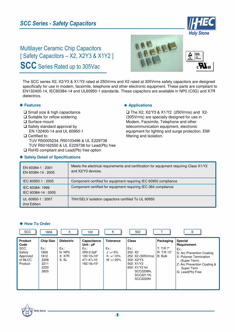
[ Safety Capacitors – X2, X2Y3 & X1Y2 ]
SCC Series Rated up to 305Vac
Safety Detail of Specifications
The SCC series X2, X2/Y3 & X1/Y2 rated at 250Vrms and X2 rated at 305Vrms safety capacitors are designed
specifically for use in modem, facsimile, telephone and other electronic equipment. These parts are compliant to
EN132400-14, IEC60384-14 and UL60950-1 standards. These capacitors are available in NP0 (C0G) and X7R
dielectrics.
Product CodeSCC:
SafetyApproved of MLCCProduct
Chip Size
Ex.:
18081812 220822112220
2825
Dielectric
Ex.:
N: NP0X: X7RS: SL
CapacitanceUnit : pFEx.:
2R0:2.0pF100:10×100
471:47×101
182:18×102
Tolerance
Ex.:
J :+/-5%K :+/-10%M :+/-20%
Class
Ex.:
202: X2252 :X2 (305Vrms)302: X2/Y3502: X1/Y2602: X1/Y2 for
SCC2208N,SCC2211N,SCC2220N
Packaging
T: T/R 7”
R: T/R 13”B: Bulk
SpecialRequirement
Ex.:S: Arc Prevention CoatingX: Polymer Termination
(Super Term)Z: Arc Prevention Coating &
Super TermG: Lead(Pb) Free
EN 60384-1 : 2001
EN 60384-14 : 2005
Meets the electrical requirements and certification for equipment requiring Class X1/Y2
and X2/Y3 devices.
IEC 60950-1 : 2005 Component certified for equipment requiring IEC 60950 compliance
IEC 60384: 1999
IEC 60384-14 : 2005
Component certified for equipment requiring IEC-384 compliance
UL 60950-1 : 2007
2nd Edition
TNV/SELV isolation capacitors certified To UL 60950
SCC Series - Safety Capacitors
Holy Stone
Features Applications
SCCSCC 18081808 XX 102102 KK 502502 TT SS
- 9 -
Small size & high capacitance
Suitable for reflow soldering
Surface mount
Safety standard approval by
EN 132400-14 and UL 60950-1
Certified to:
TUV R50005234, R50103496 & UL E229738
TUV R50162550 & UL E229738 for Lead(Pb) free
RoHS compliant and Lead(Pb) free option
The X2, X2/Y3 & X1/Y2 (250Vrms) and X2-
(305Vrms) are specially designed for use in
Modem, Facsimile, Telephone and other
telecommunication equipment, electronic
equipment for lighting and surge protection, EMI
filtering and Isolation.

Capacitance Range
Rated Voltage AC 250Vrms and AC 305Vrms
Temperature CoefficientNP0 : < 30ppm/ , -55 ~ +125 (EIA Class Ι)
X7R : < ± 15% , -55 ~ +125 (EIA Class Ⅱ)
Capacitance Range
X2/Y3 : 2.0pF ~ 2700pF , X1/Y2 : 2.0pF ~ 4700pF
X2 – 250Vrms : 150pF ~ 56nFX2 – 305Vrms : 150pF ~ 33nF
Quality and Dissipation Factor NP0 : Q≧1000 , X7R : D.F.≦2.5%
Climatic Category -55/125/21
Insulation Resistance 10GΩVoltage Proof
X Capacitor : Applied Voltage 1075Vdc(4.3Ur)Y Capacitor : Applied Voltage 1500Vac
Impulse Y3 : 2.5KV (Compliant to IEC 60950) , X2 : 2.5KV / Y2 : 5KV for three times
Aging NP0: 0 % , X7R: 1.0 % per decade hr., typical
Summary of Specifications
X : Across The Line (Ex.: SCC1808N151K302T)
Y : Line By Pass (Ex.: SCC2211X102K502T)
Y
Application Example Circuit
Y Tip & Ring
X
TNV SELV
2nd 1st
SCC Series - Safety Capacitors
Holy Stone
- 10 -
250Vrms
2R
05R
06R
88R
2100
120
150
180
220
270
330
360
390
470
560
680
820
101
121
131
151
181
221
271
331
391
471
561
681
821
102
122
152
182
222
272
332
472
473
563Class Size
Temperature
Characteristic
Rated
VoltageCertificated
X1/Y2
Capacitance Range
1808 250Vrms TUV/ULSL
‘X’ denotes values that have been tested to a rated voltage of 305Vac. TUV test report number 28208004 dated 27th May 2010
250Vrms
2R
05R
06R
88R
2100
120
150
180
220
270
330
360
390
470
560
680
820
101
121
131
151
181
221
271
331
391
471
561
681
821
102
122
152
182
222
272
332
472
473
563
x x x x x x x x x x x x
101
121
131
151
181
221
271
331
391
471
561
681
821
102
122
152
182
222
272
332
472
562
682
822
103
123
153
183
223
273
333
393
473
563
683
823
104
124
184
224
X7R 250Vrms TUV/UL
CertificatedCapacitance Range
Class SizeTemperature
Characteristic
Rated
Voltage
TUV/UL
1808 X7R 250Vrms TUV/ULX2/Y3
1808 NP0 250Vrms
1812 X7R 250Vrms TUV
X1/Y2
1808 NP0 250Vrms TUV/UL
1808 X7R 250Vrms TUV/UL
1812 X7R 250Vrms TUV/UL
2208 X7R 250Vrms TUV/UL
2208 NP0 250Vrms TUV/UL
2211 X7R 250Vrms TUV/UL
2211 NP0 250Vrms TUV/UL
TUV
2220 NP0 250Vrms TUV/UL
2220 X7R 250Vrms TUV/UL
Rated
Voltage
2825 X7R 250VrmsX2
2220
Class CertificatedSizeTemperature
Characteristic
Capacitance Range
1812 NP0 250Vrms TUV/UL
305Vrms
100
120
150
180
220
270
330
360
390
470
560
680
820
101
121
131
151
181
221
271
331
391
471
561
681
821
102
122
152
182
222
272
332
472
103
153
223
333
473
563Class SizeTemperature
Characteristic
Rated
VoltageCertificated
X2
Capacitance Range
2220 305Vrms TUVX7R

Multilayer Ceramic Chip Capacitors
[ Trigger Capacitors for Strobe ]
TCX Series
How To Order
Operation Temperature -55 ~ +125 Rated Voltage 350Vdc and 630Vdc
Temperature Coefficient X7E : ≤ ± 4.7% , -55 ~ +125 (EIA Class II )
Capacitance Range 1.0nF to 100nF
Dissipation Factor 1.0% max. at 1KHz 25Insulation Resistance 10GΩ or 500/CΩ whichever is smaller (C in Farads)
Dielectric Strength 350Vdc : 200% Rated Voltage
650Vdc : 150% Rated Voltage
Capacitance Tolerance ± 5% , ± 10% , ± 20%
Aging 1.0% per decade hr., typical
Summary of Specifications
Features
TCXTCX 12061206 CC 223223 KK 631631 TT
Product Code
TCX:
TriggerCapacitor
Chip Size
Ex.:
08051206 1210
Dielectric
C: X7E
CapacitanceUnit : pFEx.:
102 : 10×102
473 : 47×103
Tolerance
Ex.:
J : +/- 5%K : +/- 10%M : +/- 20%
Rated Voltage
Ex.:
351 : 350Vdc631 : 630Vdc
Packaging
T: T&R 7”
R: T&R 13”B: Bulk
Applications
Excellent trigger characteristics
Low ESR & Low Tan δ Excellent DC Bias
Provide good damping characteristics
results in more light
RoHS compliant
Suitable for strobe trigger circuit in digital and
electric cameras.
The TCX series is specifically designed with a proprietary material for discharge applications such as
strobe circuit applications. The unique properties of the X7E material, and the design of the TCX series,
make them suitable for any discharge application which requires the capacitor to have a good damping
characteristic.
The TCX series is also suitable for applications in which a minimum change in capacitance over
temperature (T/C) is desired. The TCX series is offered in sizes 0805, 1206 and 1210 and at 350Vdc
and 630Vdc.
TCX Series - Trigger Capacitors for Strobe
Holy Stone
- 11 -

102
122
152
182
222
272
332
392
472
562
682
822
103
123
153
183
223
273
333
393
473
563
683
823
104
154
224
C C C C C C C C C C C C C C C D D D
C C C C C C D E E
D D D D D D D E E E E
D D D D D D D D D E E E E
D D D D D D D E E
Capacitance RangeDielectric
CharacteristicSize Voltage
630V
1210350V
X7E
630V
350V0805
350V1206
Characteristics
Capacitance Range
Dimensions
W
T
BW B
L
Application Example of Circuit
+
-
DSC Strobe Circuit
Trigger Cap.
TYPE L W T (max) B (min) BW (min)
0805 2.00±0.20[.079±.012]
1.25±0.20[.049 ±.008]
1.45[.057]
0.70[.028]
0.20[.008]
1206 3.20±0.30[.126±.012]
1.60±0.20[.063±.008]
1.80[.071]
1.50[.059]
0.30[.012]
1210 3.20±0.30[.126±.012]
2.50±0.20[.098±.008]
1.80 [.071]
1.60 [.063]
0.30[.012]
Unit : mm [inches]
Other dimensions, capacitance values and voltages rating are available. Please contact Holy Stone.
TCX Series - Trigger Capacitors for Strobe
Holy Stone
Damping (Trigger) Properties
-4000
-3000
-2000
-1000
0
1000
2000
3000
4000
5000
0 1 2 3 4 5 6 7 8 9 10
Time (µs)
Tri
gg
er
Vo
lta
ge
(V
p)
TCX/1206/223K/630V
X7R/1206/223K/630V
R-C Charge Curv e
0
50
100
150
200
250
300
0 1 2 3 4 5 6 7
Time (sec.)
Vo
lta
ge
(V
)
TCX/1206/223K/630V
X7R/1206/223K/630V
- 12 -
Symbol Code S O A B C D E F G HThickness(mm) 0.3±0.03 0.5±0.05 0.6±0.1 0.85±0.1 1.0±0.1 1.25±0.20 1.6±0.2 2.0±0.2 2.4±0.2 2.8±0.2
Multilayer Ceramic Chip Capacitors
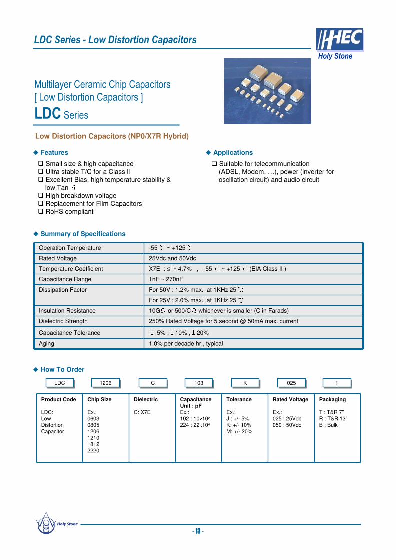
[ Low Distortion Capacitors ]
LDC Series
LDCLDC 12061206 CC 103103 KK 025025 TT
Product Code
LDC: LowDistortion
Capacitor
Chip Size
Ex.:06030805
1206121018122220
Dielectric
C: X7E
CapacitanceUnit : pFEx.:102 : 10×102
224 : 22×104
Tolerance
Ex.:J : +/- 5%K: +/- 10%
M: +/- 20%
Rated Voltage
Ex.:025 : 25Vdc050 : 50Vdc
Packaging
T : T&R 7”R : T&R 13”B : Bulk
Operation Temperature -55 ~ +125 Rated Voltage 25Vdc and 50Vdc
Temperature Coefficient X7E : ≤ ± 4.7% , -55 ~ +125 (EIA Class II )
Capacitance Range 1nF ~ 270nF
Dissipation Factor For 50V : 1.2% max. at 1KHz 25 For 25V : 2.0% max. at 1KHz 25
Insulation Resistance 10GΩ or 500/CΩ whichever is smaller (C in Farads)
Dielectric Strength 250% Rated Voltage for 5 second @ 50mA max. current
Capacitance Tolerance ± 5% , ± 10% , ± 20%
Aging 1.0% per decade hr., typical
How To Order
Summary of Specifications
Suitable for telecommunication
(ADSL, Modem, …), power (inverter for
oscillation circuit) and audio circuit
Features Applications
Low Distortion Capacitors (NP0/X7R Hybrid)
Small size & high capacitance
Ultra stable T/C for a Class ll
Excellent Bias, high temperature stability &
low Tan δ High breakdown voltage
Replacement for Film Capacitors
RoHS compliant
LDC Series - Low Distortion Capacitors
Holy Stone
- 13 -

102
122
152
182
222
272
332
392
472
562
682
822
103
123
153
183
223
273
333
393
473
563
683
823
104
154
224
274
B B B B B B B B B B B B B
C C C C C C C C C C C
C C C C C C C C C C C C C
C C C C C C C C C C C C C
C C C C C C
D D D D D D
D
Capacitance Range
50V2220
50V
1210 50V
50V0603
1812 50V
X7E
Dielectric
CharacteristicSize
Rated
Voltage
50V
25V1206
0805
W
T
BW B
L
TYPE L W T (max) B (min) BW (min)
0603 1.60±0.10[.063±.004]
0.80±0.10[.031 ±.004]
0.95[.037]
0.40[.016]
0.15[.006]
0805 2.00±0.20[.079±.012]
1.25±0.20[.049 ±.008]
1.45[.057]
0.70[.028]
0.20[.008]
1206 3.20±0.30[.126±.012]
1.60±0.20[.063±.008]
1.80[.071]
1.50[.059]
0.30[.012]
1210 3.20±0.30[.126±.012]
2.50±0.20[.098±.008]
1.80 [.071]
1.60 [.063]
0.30[.012]
1812 4.60±0.30[.181±.012]
3.20±0.30[.126±.012]
2.20[.087]
2.50[.098]
0.30[.012]
2220 5.70±0.40[.220±.016]
5.00±0.40[.197±.016]
2.20[.087]
3.50[.137]
0.30[.012]
Characteristics
Application Example of Circuit
FILTER6.8nF
6.8nF
819R
100R
100R
1.8nF
1.8nF
1
2
4.7nF
316R
50Ω50Ω
Dimensions
Capacitance Range
Unit : mm [inches]
Other dimensions, capacitance values and voltages rating are available. Please contact Holy Stone.
LDC Series - Low Distortion Capacitors
Holy Stone
Temperature Capacitance Coefficient
-20.0
-15.0
-10.0
-5.0
0.0
5.0
10.0
15.0
20.0
-55 -45 -35 -25 -15 -5 5 15 25 35 45 55 65 75 85 95 105 115 125
Temperature
dC
/C (
%)
X7R 1206/103
LDC 1206/103
Impedance/ESR & Frequency
0.01
0.1
1
10
100
0.1 1 10 100 1000
Frequency (MHz)
(ohm
)
Z - LDC/1206/103
Z - Film Cap 1206/103
ESR - LDC/1206/103
ESR - Film Cap /1206/103
Temperature
- 14 -
Symbol Code S O A B C D E F G HThickness(mm) 0.3±0.03 0.5±0.05 0.6±0.1 0.85±0.1 1.0±0.1 1.25±0.20 1.6±0.2 2.0±0.2 2.4±0.2 2.8±0.2

Applications
Multilayer Ceramic Chip Capacitors
[ Normal Chip Capacitors – NP0,X7R,X5R,Y5V ]
NCC Series
Summary of Specifications
Standard Multilayer Ceramic Chip Capacitors are available in a full range of sizes and temperature
coefficients, with voltage ratings from 6.3V to 50V.
Surface mount suitable for wave and reflow
soldering
Small size and high reliability
Excellent in high frequency characteristics
RoHS compliant
Suitable for general electronics circuit,
telecommunication, personal computers and
peripheral, power circuit, mobile application & etc ….
Features
NCC Series - Normal Chip Capacitors
Holy Stone
- 15 -
Operation Temperature NP0 & X7R : -55 ~ +125 , X5R : -55 ~ +85 , Y5V : -30 ~ +85 Rated Voltage 6.3Vdc to 50Vdc
Temperature Coefficient NP0 : ≤ ± 30ppm/ , -55 ~ +125 (EIA Class Ι)
X7R : ≤ ± 15% , -55 ~ +125 (EIA Class Ⅱ)
X5R : ≤ ± 15% , -55 ~ +85 (EIA Class Ⅱ)
Y5V: +22%/-82% , -30 ~ +85 (EIA Class Ⅱ)
Dissipation Factor NP0 : More than 30pF: Q≥ 1000 (0.001) , 30pF and below : Q≥400+20C (C=pF)
X7R, X5R and Y5V: Please see HEC specification data sheet
Insulation Resistance 10GΩ or 500/CΩ whichever is smaller (C in Farads)
Aging NP0 : 0% , X7R/X5R : typically 1.0% , Y5V ≤ 7% per decade of time
Dielectric Strength 250% Rated Voltage
Dimensions
W
T
BW B
L
TYPE L W T (max) B (min) BW (min)
0201 0.60±0.03[.024±.001]
0.30±0.03[.011 ±.001]
0.33[.013]
0.20[.008]
0.10[.004]
0402 1.00±0.05[.039±.002]
0.50±0.05[.020 ±.002]
0.55[.022]
0.30[.012]
0.15[.006]
0603 1.60±0.10[.063±.004]
0.80±0.10[.031 ±.004]
0.95[.037]
0.40[.016]
0.15[.006]
0805 2.00±0.20[.079±.012]
1.25±0.20[.049 ±.008]
1.45[.057]
0.70[.028]
0.20[.008]
1206 3.20±0.30[.126±.012]
1.60±0.20[.063±.008]
1.80[.071]
1.50[.059]
0.30[.012]
Product Code
C: MLCC(MultilayerCeramic Chip of
Capacitor)
Chip Size
Ex.:0201 0402 0603
08051206
Dielectric
Ex.:N: NP0X: X7RB:X5R
Y:Y5V
Capacitance
Unit : pFEx.:102 : 10×102
473 : 47×103
104 : 10×104
Tolerance
Ex.:C : +/- 0.25pFD : +/- 0.50pFF : +/- 1%
G : +/- 2%J : +/- 5%K : +/- 10%M : +/- 20%Z : +80/-20%
Rated Voltage
Ex.:007 : 6.3Vdc010 : 10Vdc016 : 16Vdc
025 : 25Vdc050 : 50Vdc
Packaging
T: T&R 7”R: T&R 13”B: Bulk
How To Order
CC 04020402 BB 104104 KK 010010 TT

101
121
151
181
221
271
331
391
471
561
681
102
122
152
182
222
272
332
392
472
562
682
822
103
123
153
183
223
273
333
393
473
563
683
823
104
154
224
334
474
684
824
S
S S S S S S
S S S S S S S S S S S S S S
O
O O O O O O O O O O O O O
O O O O O O O O O O O O O
O O O O O O O O O O O O O O O O O O O O O O O O O O O O
B B B B B B
B B B B B B B B B B B B B B B B B B B B B B B B B B B B B B B B B B B B B B B
B B B B B B B B B B B B B B B B B B B B B B B B B B B B B B B B B B B B B B
B B B B B B B B B B B B B B B B B B B B B B B B B B B B B B B B B B
B B B B B B B B B B B B B B B B B B B B B B B B B B B B B D D D D
B B B B B B B B B B B B B B B B B B B B B B B B B B B B B D D D D
B B B B B B B B B B B B B B B B B B B B B B B B B B B B B D D D
B B B B B B B B B B B B B B B B B B B B B B B B B B B B B C D D
B B B B B B
B B B C D D
B B B C D D E
0603
6.3V
25V
25V
16V
16V
25V
50V
50V
10V
16V
Dielectric
CharacteristicSize
0201
Rated
Voltage
25V
10V
0805
0402
25V
Capacitance Range
X7R
1206
50V
16V
35V
50V
16V
0R
51R
01R
52R
03R
04R
05R
06R
07R
08R
09R
0100
120
150
180
220
270
330
390
470
560
680
820
101
121
151
181
221
271
331
391
471
561
681
821
102
222
332
472
562
682
103
S S S S S S S S S S S S S S S S S S S S S S S S
S S S S S S S S S S S S S S S S S S S S S S S S
O O O O O O O O O O O O O O O O O O O O O O O O O O O O O O O O
B B B B B B B B B B B B B B B B B B B B B B B B B B B B B
B B B B B B B B B B B B B B B B B B B B B B B B
Capacitance Range Rated
Voltage
16V
25V
50V
Dielectric
Characteristic
NPO 0402
Size
0201
50V
0603
0805
50V
Capacitance Range
Other dimensions, capacitance values and voltages rating are available. Please contact Holy Stone.
NCC Series - Normal Chip Capacitors
Holy Stone
-16 -
Symbol Code S O A B C D EThickness(mm) 0.3±0.03 0.5±0.05 0.6±0.1 0.85±0.1 1.0±0.1 1.25±0.20 1.6±0.2
10
22
22
47
21
03
22
34
73
10
42
24
47
4
O O
O
B B B
B B B
B
B B B
B B B
B B B
B B B
B B B
B B B
Capacitance RangeDielectric
CharacteristicSize
Rated
Voltage
25V
50V
1206
16V
25V
50V
Y5V
040210V
16V
0603
16V
25V
50V
0805
16V
27
333
339
347
356
368
382
310
415
422
433
447
468
4
S S S
O O
O O O
O O O O O O O O
O O O O O O O O
B B
B B B B B BB
B B B B B B
B B B B BB
X5R
Dielectric
CharacteristicSize Rated
Voltage
6.3V
10V
6.3V
10V
16V
25V
0402
16V
25V
0603
Capacitance Range
0201 6.3V

Surface mount suitable for wave and reflow
soldering
High reliability
Small size and high capacitance value
Excellent high frequency characteristics
RoHS compliant
Multilayer Ceramic Chip Capacitors
[ High Capacitance MLCC – 1.0uF and above ]
HCC Series
Summary of Specifications
Features Applications
Ideal for smoothing and decoupling circuits
Suitable for DC-DC converter, personal
computer and peripherals, telecommunication
and general electronic equipment
HCC Series - High Capacitance MLCC
Holy Stone
- 17 -
Operation Temperature NP0 & X7R : -55 ~ +125 , X6S : -55 ~ +105 ; X5R : -55 ~ +85 , Y5V : -30 ~ +85
Rated Voltage 4.0Vdc to 50Vdc
Temperature Coefficient X7R : ≤ ± 15% , -55 ~ +125 (EIA Class Ⅱ)
X6S : ≤ ± 22% , -55 ~ +105 (EIA Class Ⅱ)
X5R : ≤ ± 15% , -55 ~ +85 (EIA Class Ⅱ)
Y5V : +22%/-82% , -30 ~ +85 (EIA Class Ⅱ)
Dissipation Factor X7R, X5R and Y5V : Please see HEC specification data sheet
Insulation Resistance 10GΩ or 500/CΩ whichever is smaller (C in Farads)
Aging X7R/X6S/X5R : typically 1.0% and Y5V ≤ 7% per decade of time
Dielectric Strength 250% Rated Voltage
DimensionsTYPE L W T (max) B (min) BW (min)
0402 1.00±0.05[.039±.002]
0.50±0.05[.020 ±.002]
0.55[.022]
0.30[.012]
0.15[.006]
0603 1.60±0.10[.063±.004]
0.80±0.10[.031 ±.004]
0.95[.037]
0.40[.016]
0.15[.006]
0805 2.00±0.20[.079±.012]
1.25±0.20[.049 ±.008]
1.45[.057]
0.70[.028]
0.20[.008]
1206 3.20±0.30[.126±.012]
1.60±0.20[.126±.012]
1.80[.071]
1.50[.059]
0.30[.012]
1210 3.20±0.30[.126±.012]
2.50±0.20[.098±.008]
2.70 [.105]
1.60 [.063]
0.30[.012]
1812 4.60±0.3[.181±.012]
3.20±0.3[.126±.012]
3.00[.118]
2.50[.098]
0.30[.012]
2220 5.7±0.40[.220±.016]
5.00±0.40[.197±.016]
3.00 [.118]
3.50 [.137]
0.30[.012]
W
T
BW B
L
Product Code
C: MLCC(MultilayerCeramic Chip of Capacitor)
Chip Size
Ex.0402 0603 0805 1206
1210 18122220
Dielectric
Ex.:X:X7RS:X6SB:X5RY:Y5V
CapacitanceUnit : pF
Ex.:105:10×105
106:10×106
226:22×106
Tolerance
Ex.:J : +/- 5%K: +/- 10%M:+/- 20%Z :+80/-20%
Rated Voltage
Ex.:004: 4Vdc007: 6.3Vdc010: 10Vdc016: 16Vdc
025: 25Vdc035: 35Vdc050: 50Vdc
Packaging
T: T&R 7”R: T&R 13”B: Bulk
How To Order
CC 08050805 BB 106106 KK 010010 TT

Size
Code 10V 16V 25V 35V 50V
105 O B B B B D D E E E225 B B D D D E E E E F F F475 B D D D D E E E E E E F F F F106 D D D E E E E F F F F G226 D E E G G G
50V6.3V 10V 25V 10V 35V10V16V16V 25V 6.3V6.3V 6.3V 16V 25V
1210
X6S (S) Series
0805 12060402 0603
Size
Code
105 O O B B B B B D225 B B B D D D475 B B D D D106 D D D D D/E E F F F226 D D D/E D/E F F
1206
Y5V (Y) Series
12100402 0603 0805
6.3V 10V 6.3 10V 16V 25V 6.3V 10V 16V 25V 50V 10V 16V 25V 10V 16V 25V 35V
Size
Code 16V 25V 35V 6.3V
105 B B B B D D D D D D D D D/E D/E D/E D/E D D D D E F F F155 D F225 B B D D D D D D E E E E E E F F F F F F F F335 D D E E E F475 D D D D E E E E E E F F F F F F F F106 D D D E E E E F F F F G G G226 E E G G G
1206 1210
35V
1812
25V 50V 50V10V 16V 25V 50V
22200603
6.3V 10V 25V 6.3V 25V 35V 50V10V
0805
16V 50V 10V 16V
X7R (X) Series
Size
Code
105 B B B D D D E E E E E E E F F155 F F225 B B B D D D E E E E E/F F F F335 D D E E F475 D D D E E E E F F F106 D E E E E F G226 G
35V 35V10V 16V 25V 35V25V 35V 50V10V 16V 25V 10V 16V6.3V 10V 16V 6.3V
X7R (X) Series
0603 0805 1206 1210 18122220
Capacitance Range
Other dimensions, capacitance values and voltages rating are available. Please contact Holy Stone.
HCC Series - High Capacitance MLCC
Holy Stone
- 18 -
Symbol Code S O A B C D E F GThickness(mm) 0.3±0.03 0.5±0.05 0.6±0.1 0.85±0.1 1.0±0.1 1.25±0.20 1.6±0.2 2.0±0.2 2.5±0.2

Multilayer Ceramic Chip Capacitors
[ High Cap. NP0 ]
HCN Series
Small size & high Capacitance
Suitable for wave and reflow soldering
Excellent characteristics and tight tolerances
Excellent Bias, high temperature stability &
low Tan δ Replace Film Capacitors
RoHS compliant
CC 12061206 NN 103103 JJ 025025 TT
Product Code
C: MLCC(MultilayerCeramic
Chip of Capacitor)
Chip Size
Ex.:0603 0805
1206 1210 1812
Dielectric
N: NP0
CapacitanceUnit : pFEx.:102 : 10×102
103 : 10×103
124 : 12×104
Tolerance
Ex.:F : +/- 1%G : +/- 2%
J : +/- 5%
Rated Voltage
Ex.:016:16Vdc025:25Vdc
050:50Vdc
Packaging
T: T&R 7”R: T&R 13”B: Bulk
Replacement for Film Capacitor
Operation Temperature -55 ~ +125 Rated Voltage 16Vdc to 50Vdc
Temperature Coefficient NP0 : ≤ 30ppm/ , -55 ~ +125 (EIA Class Ι)
Capacitance Range 1nF ~ 120nF
Dissipation Factor Q ≥1000 at 1KHz 20 Insulation Resistance 10GΩ or 500/C Ω whichever is smaller (C in Farad)
Dielectric Strength 250% Rated Voltage for 5 second @ 50mA max. current
Aging 0% per decade hr.
How To Order
Summary of Specifications
Features Applications
Suitable for ADSL filter circuits,
cable Modem and coupling circuits,
general Telecommunication use,
power (Inverter for oscillation circuit) and
audio circuit
HCN Series - High Cap NP0
Holy Stone
- 19 -

Characteristics
Application Example Circuits
Dimensions
Capacitance Range
680uH
Tx Filter
560pF
560pF
1.5nF 2.7nF
4.75KR
4.75KR680uH
348R
348R
1
2
Unit : mm [inches]
Z/ESR & Frequency
0.001
0.01
0.1
1
10
100
1000
10000
100000
0.1 1 10 100 1000 10000 100000
Frequency (KHz)
Ohm
Z- MLCC- NPO 1812/683
ESR-MLCC NPO 1812/683
Z- Film Cap 1812/683
ESR- Film Cap 1812/683
Temperature Capacitance Coefficient
-5000
-4000
-3000
-2000
-1000
0
1000
2000
3000
4000
5000
-55 -45 -35 -25 -15 -5 5 15 25 35 45 55 65 75 85 95 105 115 125
Temperature()
dC
/C (
ppm
)
NPO-1812/683
Film-1812/683
Rx Filter1.5nF
1.5nF
1.8nF
1.8nF
1.8nF
1.8nF
3.3nF
3.3nF
6.8nF
680uH 680uH 680uH
4.7nF 18nF 4.2KR
4.2KR
100nF2
1
Other dimensions, capacitance values and voltages rating are available. Please contact Holy Stone.
TYPE L W T (max) B (min) BW (min)
0603 1.60±0.10[.063±.004]
0.80±0.10[.031±.004]
0.95[.037]
0.40[.016]
0.15[.006]
0805 2.00±0.20[.079±.008]
1.25±0.20[.049 ±.008]
1.45[.057]
0.70[.028]
0.20[.008]
1206 3.20±0.30[.126±.012]
1.60±0.20[.126±.008]
1.80[.071]
1.50[.059]
0.30[.012]
1210 3.20±0.30[.126±.012]
2.50±0.20[.098±.008]
2.20 [.087]
1.60 [.063]
0.30[.012]
1812 4.60±0.30[.181±.012]
3.20±0.30[.126±.012]
2.20[.087]
4.00[.157]
0.30[.012]
HCN Series - High Cap NP0
Holy Stone
W
T
BW B
L
- 20 -
Symbol Code S O A B C D E FThickness(mm) 0.3±0.03 0.5±0.05 0.6±0.1 0.85±0.1 1.0±0.1 1.25±0.2 1.6±0.2 2.0±0.2
102
122
152
182
222
272
332
392
472
562
682
822
103
123
153
183
223
273
333
393
473
563
683
823
104
124
154
224
B B B B B B B
B B B B B B B
B B B B B B B
B B B B C/D D D D D D D D D
B B B B C/D D D D D D D D D
B B B B C/D D D D D D D D D
B B B B B B B B B B B B B D D D D E E
B B B B B B B B B B B B B D D D D E E
B B B B B B B B B B B B B D D D D E E
C C C C C C C C C C C C C D D D D D E E E
C C C C C C C C C C C C C D D D D D E E E
C C C C C C C C C C C C C D D D D D E E E
D D D D D D D D D D D D D D D D E E E E F F F F F F
D D D D D D D D D D D D D D D D E E E E F F F F F F
D D D D D D D D D D D D D D D D E E E E F F F F F F
1812
16V
25V
50V
16V
25V
50V
1210
16V
25V
50V
NPO
0603
16V
25V
50V
0805
16V
25V
50V
1206
Dielectric
CharacteristicSize Voltage
Capacitance Range

Multilayer Ceramic Chip Capacitors
[ High Cap. X7R ]
HCX Series
Product Code
C: MLCC(MultilayerCeramic Chip of Capacitor)
Chip Size
Ex.:1210 1812 1825 2220
2225
Dielectric
X: X7R
CapacitanceUnit : pF
Ex.:102 : 10×102
224 : 22×104
105 : 10×105
Tolerance
Ex.:K : +/- 10%M : +/- 20%
Rated Voltage
Ex.:050 : 50Vdc101 : 100Vdc
Packaging
T: T&R 7”R: T&R 13”B: Bulk
SpecialRequirement
Ex.:O: Arc
PreventionCoating
X: Cushion
Termination
(Super Term)
Operation Temperature -55 ~ +125 Rated Voltage 50Vdc to 100Vdc
Temperature Coefficient X7R : ≤ ± 15% at -55 ~ +125 (EIA Class II )
Capacitance Range 100nF ~ 10uF
Dissipation Factor 2.5% max. at 1KHz 25 Insulation Resistance 10GΩ or 500/C Ω whichever is smaller (C in Farad )
Dielectric Strength 50V : 250% Rated Voltage for 5 second @ 50mA max. current
100V : 200% Rated Voltage for 5 second @ 50mA max. current
Capacitance Tolerance ± 10% , ± 20%
Aging 1.0% per decade hr., typical
How To Order
Summary of Specifications
Features Applications
DC-DC Converters (filter)
Industrial controls
Power supplies
Surge protection
Rated working voltage of 50Vdc and 100Vdc
Small size & high capacitance
Excellent Bias, high temperature stability &
low Tan δ Low ESR and excellent ripple current
characteristics
RoHS compliant
HCX Series - High Cap X7R
Holy Stone
CC 12101210 XX 225225 KK 101101 TT XX
- 21 -

TYPE L W T (max) B (min) BW (min)
1210 3.20±0.30[.126±.012]
2.50±0.20[.098±.008]
2.60 [.102]
1.60 [.063]
0.30[.012]
1812 4.60±0.30[.181±.012]
3.20±0.30[.126±.012]
3.00[.118]
2.50[.098]
0.30[.012]
1825 4.60±0.30[. 181±.012]
6.35±0.40[.250±.016]
3.00[.118]
2.50[.098]
0.30[.012]
2220 5.70±0.40[.220±.016]
5.00±0.40[.197±.016]
3.00[.118]
3.50[.137]
0.30[.012]
2225 5.70±0.40[.220±.016]
6.35±0.40[.250±.016]
3.00[.118]
3.50[.137]
0.30[.012]
W
T
BW B
L
Characteristics
Application Example Circuit
Dimensions
Capacitance Range
Filter Isolation
Transformer
DC-DC Converter
Unit : mm [inches]
Other dimensions, capacitance values and voltages rating are available. Please contact Holy Stone.
HCX Series - High Cap X7R
Holy Stone
Impadance/ESR & Frequency
0.01
0.1
1
10
100
1 10 100 1000 10000 100000
Frequency (KHz)
(o
hm
)
ESR-1812/155
Z -1812/155
Ripple Current
1
10
100
1000
0 0.5 1 1.5 2 2.5 3 3.5
Ripple Current (Arms)
Chip
Surf
ace
Tem
p.(∆
C)
10KHz -1812/155
100KHz-1812/155
300KHz-1812/155
- 22 -
Code WVDC
104 100nF154 150nF224 220nF334 330nF474 470nF564 560nF684 680nF105 1uF155 1.5uF225 2.2uF335 3.3uF475 4.7uF685 6.8uF106 10uF
50V 100V
2220 2225
50V 100V 50V 100V 50V 100V 50V 100V
Size 1210 1812 1825

Product Code
C: MLCC
(MultilayerCeramic Chip of Capacitor)
Chip Size
Ex.:
0805 1206 1210 1812 2220
Dielectric
Ex.:
X : X7RE : Y5U
CapacitanceUnit : pFEx.:
103 : 10×103
474 : 47×104
Tolerance
Ex.:
K : +/- 10%M : +/- 20%
Rated Voltage
Ex.:
251 : 250Vdc
Packaging
T: T&R 7”
R: T&R 13”B: Bulk
Multilayer Ceramic Chip Capacitors
[ Tip & Ring Capacitors ]
SAC Series
How To Order
Summary of Specifications
FeaturesTelephone lines use a DC voltage of 48 volts and
pass the subscriber’s AC signal pulse of 15 to 25Hz,
at 70 to 90Vrms.
These MLCC Tip & Ring capacitors replace bulky
leaded film capacitors and offer excellent frequency
response, low ESR, and improved temperature
characteristics. Ideal for telecommunication and
modem applications.
Small size & high capacitance
Suitable for wave and reflow soldering
Surface mount
Low ESR characteristics & improved
temperature performance
RoHS compliant
SAC Series - Tip & Ring Capacitors
Holy Stone
CC 18121812 XX 474474 MM 251251 TT
- 23 -
Operation temperature X7R : -55 ~ +125 , Y5U : -30 ~ +85 Rated Voltage 250Vdc
Temperature Coefficient Y5U : ≤ +22 /-56 % , -30 ~ +85 (EIA Class II )
X7R : ≤ ± 15% , -55 ~ +125 (EIA Class II )
Capacitance Range Y5U : 10nF ~ 1.0uF
X7R : 180pF ~ 2.2uF
Dissipation Factor Y5U : D.F.≦4.0% , X7R : D.F.≦2.5%
Insulation Resistance 10GΩ or 500/CΩ whichever is smaller (C in Farads)
Dielectric Strength 200% Rated Voltage for 5 second @ 50mA max. current
Aging Y5U : 4.0 % , X7R: 1.0 % per decade hr., typical

18
1
22
1
27
1
33
1
47
1
68
1
10
2
15
2
18
2
22
2
33
2
47
2
56
2
68
2
10
3
15
3
22
3
27
3
33
3
39
3
47
3
56
3
68
3
82
3
10
4
15
4
22
4
33
4
47
4
56
4
68
4
82
4
10
5
15
5
22
5
C C C C C C C C C C C C C C C D D D D
C C C C C C C C C C C C C C C C C C C C C C/D D/E D/E D/E
D D D D D D D D D D D D D
D D D D D D E E E E E E E E E E E F G
E E E E E E E E F F G
E E E E E E E E E E E E E E E E F F F
Capacitance Range
0805
Dielectric
CharacteristicSize Voltage
250V
X7R
1812 250V
1206 250V
Y5U 1812 250V
1210
2220
250V
250V
Capacitance Range
W
T
BW B
L
Ring
Tip
Ring
Tip
0.47uF
200ms/DIV
-48Vdc
Dimensions
Application Example Circuit
Characteristics
TYPE L W T (max) B (min) BW (min)
0805 2.00±0.20[.079±.008]
1.25±0.20[.049 ±.008]
1.45[.057]
0.70[.028]
0.20[.008]
1206 3.20±0.30[.126±.012]
1.60±0.20[.063±.008]
1.80[.071]
1.50[.059]
0.30[.012]
1210 3.20±0.30[.126±.012]
2.50±0.20[.098±.008]
2.60 [.102]
1.60 [.063]
0.30[.012]
1812 4.60±0.30[.181±.012]
3.20±0.30[.126±.012]
3.00[.118]
2.50[.098]
0.30[.012]
2220 5.70±0.40[.220±.016]
5.00±0.4[.197±.016]
3.00[.118]
3.50[.137]
0.30[.012]
Unit : mm [inches]
Other dimensions, capacitance values and voltages rating are available. Please contact Holy Stone.
SAC Series - Tip & Ring Capacitors
Holy Stone
Temperature Capacitance Coef f icient
-80
-70
-60
-50
-40
-30
-20
-10
0
10
20
-55 -35 -15 5 25 45 65 85 105 125Temperature (C)
Ca
pa
cit
an
ce
Ch
an
ge
(%
)
X7R 1812/474
Y5U 1812/474
X7R Impedance/ESR & Frequency
0.01
0.1
1
10
100
1000
10000
0.1 1 10 100 1000 10000 100000Frequency (KHz)
(o
hm
)
X7R 1812/474 -Z
X7R 1812/474 -ESR
Y5U 1812/474 -Z
Y5U 1812/474 -ESR
- 24 -
Symbol Code S O A B C D E F GThickness(mm) 0.3±0.03 0.5±0.05 0.6±0.1 0.85±0.1 1.0±0.1 1.25±0.20 1.6±0.2 2.0±0.2 2.4±0.2

Multilayer Ceramic Chip Capacitors
[ Low-Loss, High Frequency Capacitors ]
HBC Series
Low stable ESR at high frequency
Ultra stable NP0 performance
Suitable for solder wave and reflow soldering
RoHS compliant
High peak to peak voltage capability
HBCHBC 12061206 NN 100100 JJ 501501 TT
Product CodeHBC:Low-Loss High Frequency Capacitor
Chip Size
Ex.:1206 1210
Dielectric
N : NP0
CapacitanceUnit : pFEx.:100 : 10×100
101 : 10×101
102 : 10×102
Tolerance
Ex.:F : ± 1%G : ± 2% J : ± 5%K : ± 10%
Rated VoltageEx.:501 : 500Vdc631 : 630Vdc
Packaging
T: T&R 7”R: T&R 13”B: Bulk
HBC Series - Low-Loss, High Frequency Capacitors
Holy Stone
Operation Temperature -55 ~ +125 Rated Voltage 500Vdc and 630Vdc
Temperature Coefficient ≤ ± 30ppm at -55 ~ +125 Capacitance Range 10pF ~ 2700pF
Dissipation Factor 0.1% max. at 1MHz 25Insulation Resistance 10GΩDielectric Withstanding 1.5 ×WVDC for 5 sec
Capacitance Tolerance F, G, J, K
Ageing None
Piezo Effects None
dv/dt Rating >6KV/µ second
How To Order
Summary of Specifications
High frequency pulse circuits
Lighting ballast snubber circuits
DC-DC converters
High dv/dt rating
Features Applications
-25-

TYPE L W T (max) B (min) BW (min)
12063.20±0.30
[.126±.012]
1.60 ± 0.2
[.063±.008]
1.80
[.071]
1.50
[.059]
0.30
[.012]
12103.20±0.30
[.126±.012]
2.50 ± 0.2
[.098±.008]
2.60
[.102]
1.60
[.063]
0.30
[.012]W
T
BW B
L
HBC Series - Low-Loss, High Frequency Capacitors
Holy Stone
Characteristics Peak to Peak Voltage
Dimensions Unit : mm [inches]
- 26-
To convert a DC voltage rating to maximum Peak to Peak voltage, a conversion factor of 1.25:1 should be used.Example: 500VDC rating = 500/1.25 = 400V Peak to Peak voltage, where Peak to Peak is defined as below.
AC Voltage Pulsed Voltage
DC + AC Voltage
0V
DC + Pulsed Voltage
0V
= Peak to Peak voltage
100
120
150
180
220
270
330
390
470
560
680
820
101
121
151
181
221
271
331
391
471
561
681
821
102
122
152
182
222
272
Capacitance Range
1206
Size Voltage
500V
1210 630V
1206 630V
1210 500V
Capacitance Range
Other dimensions, capacitance values and voltages rating are available. Please contact Holy Stone.

Multilayer Ceramic Chip Capacitors
High Temperature Capacitors
HTC Series
[ X8R rated to +150°C]
Rated voltages from 25Vdc to 250Vdc
Stable temperature coefficient of ±15% at hightemperature (up to 150 )
Fully RoHS compliant Available with flexible termination (Super Term)
to minimize mechanical / thermal stress effects
HTCHTC 12061206 HH 103103 KK 025025 TT
Product CodeHTC: Middle HighTemperatureCapacitor
Chip Size
Ex.:06030805 12061210
Dielectric
H: X8R
CapacitanceUnit : pFEx.:102 : 10×102
224 : 22×104
Tolerance
Ex.:J : +/- 5%K : +/- 10%M : +/- 20%
Rated VoltageEx.:025 : 25Vdc050 : 50Vdc
Packaging
T: T&R 7”R: T&R 13”B: Bulk
HTC Series - High Temperature Capacitors
Holy Stone
Operation Temperature -55 ~ +150 Rated Voltage 25Vdc ~ 250Vdc
Temperature Coefficient ≤ ± 15% , -55 ~ +150 (EIA Class II )
Capacitance Range 180pF ~ 390pF
Dissipation Factor 2.5 % max. at 1KHz 25 Insulation Resistance 100GΩ or 1000/CΩ whichever is smaller at 25 (C in Farads)
Dielectric Strength < 200V : 250% Rated Voltage for 5 second @ 50mA max. current
201~500V : 150% Rated Voltage for 5 second @ 50mA max. current
Capacitance Tolerance ± 5% , ± 10% , ± 20%
Aging 2.0% per decade hr., typical
How To Order
Summary of Specifications
Suitable for automotive, oil exploration and
other demanding high temperatureenvironments and applications
Instrumentation and other equipment circuit
operating at high temperatures
Features Applications
- 27-

W
T
BW B
L
TYPE L W T (max) B (min) BW (min)
0603 1.60±0.10[.063±.004]
0.80±0.10[.031 ±.004]
0.95[.037]
0.40[.016]
0.15[.006]
0805 2.00±0.20[.079±.008]
1.25±0.20[.049 ±.008]
1.45[.057]
0.70[.028]
0.20[.008]
1206 3.20±0.30[.126±.012]
1.60±0.20[.063±.008]
1.80[.071]
1.50[.059]
0.30[.012]
1210 3.20±0.30[.126±.012]
2.50±0.20[.098±.008]
1.80 [.071]
1.60 [.063]
0.30[.012]
Characteristics
Dimensions
Capacitance Range
Holy Stone
Unit : mm [inches]
Other dimensions, capacitance values and voltages rating are available. Please contact Holy Stone.
- 28-
18
12
21
27
13
31
39
14
71
56
16
81
10
21
22
15
21
82
22
22
72
33
23
92
47
25
62
68
21
03
12
31
53
18
32
23
27
33
33
39
34
73
56
36
83
10
41
24
15
41
84
22
42
74
33
43
94
47
45
64
68
41
05
15
52
25
1210
25V
50V
100V
250V
25V
50V
100V
250V
X8R
060325V
50V
0805
25V
50V
100V
250V
1206
Temperature
CharacteristicSize Rated
Voltage
Capacitance Range
X8R-1206 / 100nF
-25.0-20.0-15.0-10.0-5.00.05.010.015.020.0-55 -40 -25 -10 5 20 35 50 65 80 95 110 125 140
dC
/C (%
)
150
HTC Series - High Temperature Capacitors
Multilayer Ceramic Chip Capacitors
[ Radio Frequency Capacitors ]
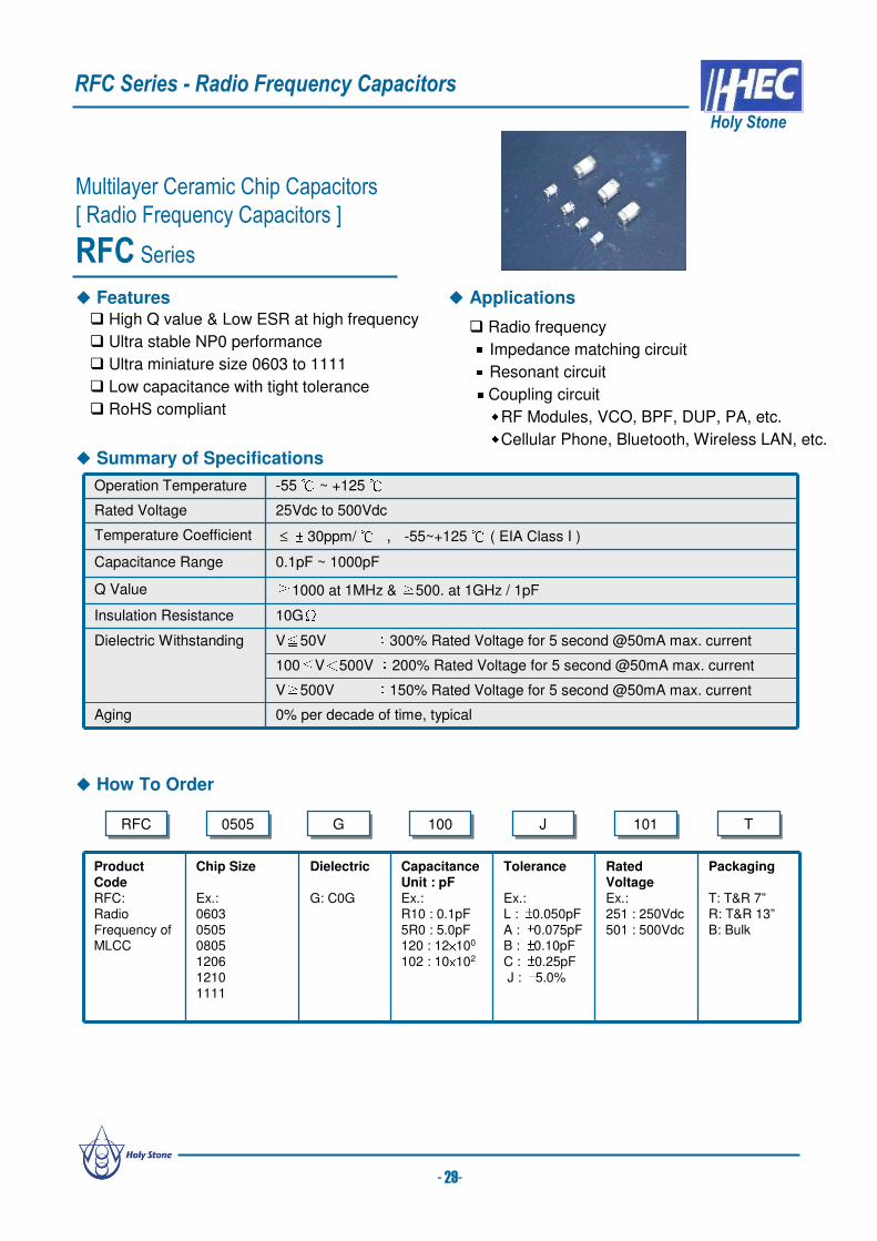
RFC Series
High Q value & Low ESR at high frequency
Ultra stable NP0 performance
Ultra miniature size 0603 to 1111
Low capacitance with tight tolerance
RoHS compliant
RFCRFC 05050505 GG 100100 JJ 101101 TT
Product Code
RFC: Radio Frequency of MLCC
Chip Size
Ex.:0603 05050805 1206 1210 1111
Dielectric
G: C0G
CapacitanceUnit : pFEx.:R10 : 0.1pF5R0 : 5.0pF120 : 12×100
102 : 10×102
Tolerance
Ex.:L : ±0.050pFA : ±0.075pFB : ±0.10pFC : ±0.25pFJ : ±5.0%
Rated Voltage
Ex.:251 : 250Vdc501 : 500Vdc
Packaging
T: T&R 7”R: T&R 13”B: Bulk
RFC Series - Radio Frequency Capacitors
Holy Stone
Operation Temperature -55 ~ +125 Rated Voltage 25Vdc to 500Vdc
Temperature Coefficient ≤ ± 30ppm/ , -55~+125 ( EIA Class I )
Capacitance Range 0.1pF ~ 1000pF
Q Value ≧1000 at 1MHz & ≧500. at 1GHz / 1pF
Insulation Resistance 10GΩDielectric Withstanding V≦50V :300% Rated Voltage for 5 second @50mA max. current
100≦V<500V :200% Rated Voltage for 5 second @50mA max. current
V≧500V :150% Rated Voltage for 5 second @50mA max. current
Aging 0% per decade of time, typical
How To Order
Summary of Specifications
Radio frequency Impedance matching circuit Resonant circuit Coupling circuitRF Modules, VCO, BPF, DUP, PA, etc.Cellular Phone, Bluetooth, Wireless LAN, etc.
Features Applications
- 29-

TYPE L W T (max) B (min) BW (min)
0603 1.60±0.10[.063±.004]
0.80±0.10[.031 ±.004]
0.95[.037]
0.40[.016]
0.15[.006]
0505 1.40±0.25[.055±.010]
1.40±0.25[.055±.010 ]
1.40[.055]
0.35[.014]
0.20[.008]
0805 2.00±0.20[.079±.008]
1.25±0.20[.049 ±.008]
1.45[.057]
0.70[.028]
0.20[.008]
1206 3.20±0.30[.126±.012]
1.60±0.20[.063 ±.008]
1.80[.071]
1.50[.059]
0.30[.012]
1210 3.20±0.30[.126±.012]
2.50±0.20[.098 ±.008]
2.60[.102]
1.60[.063]
0.30[.012]
11112.80±0.40
[.110±.016]
2.80±0.40
[.110±.016]2.60 [.102]
1.40
[.055]0.30[.012]
W
T
BW B
L
RFC Series – Radial Frequency Capacitors
Holy Stone
Characteristics
DimensionsUnit : mm [inches]
- 30-
0505-ESR vs Frequency 1111-ESR vs Frequency
0505-Q Factor vs Frequency 1111-Q Factor vs Frequency

RFC Series – Radio Frequency Capacitors
Holy Stone
- 31-
Capacitance Range
Other dimensions, capacitance values and voltages rating are available. Please contact Holy Stone.
R10
R20
R30
R40
R50
R60
R70
R80
R90
1R
0
1R
1
1R
2
1R
3
1R
5
1R
6
1R
8
2R
0
2R
2
2R
4
2R
7
3R
0
3R
3
3R
9
4R
7
5R
6
6R
8
8R
2
100
120
150
180
220
270
330
390
470
560
680
820
101
121
151
181
221
271
331
391
471
561
681
821
102
1206
200V
500V
100V
± 0.25pF ±5%Tolerance ± 0.05pF ±0.075pF ±0.1pF
500V
1210
100V
100V
200V
300V
500V
COG 0603 250V
0505 250V
0805
200V
250V
1111
50V
T.C. Size Voltage
Capacitange Range

How To Order
Multilayer Ceramic Chip Capacitors
[ Large Size Ceramic Chip Capacitors ]
LCC Series
Operation Temperature -55 ~ +125 Rated Voltage 50Vdc to 8KVdc
Temperature Coefficient NP0 : ≤ ± 30ppm/ , -55~+125 (EIA Class Ι)
X7R : ≤ ± 15% , -55~+125 (EIA Class Ⅱ )
Capacitance Range NP0 : 100pF to 820nF , X7R : 1000pF to 33uF
Dissipation Factor NP0 : Q≧1000 , X7R : D.F.≦2.5%
Insulation Resistance 10GΩ or 500/CΩ whichever is smaller (C in Farad )
Aging NP0 : 0% , X7R : 2.5 % per decade of time
Dielectric Strength V ≤ 500V : 200% Rated Voltage
500V ≤ V < 1000V : 150% Rated Voltage
V ≥1000V : 120% Rated Voltage
Summary of Specifications
Optimized internal designs offers the highest
voltage rating (up to 8KVdc)
Capacitance range from 470pF to 33uF and sizes
from 1515 to 7565
Available with proprietary surface coating for arc
prevention
Available with flexible termination (Super Term) to
minimize the effects of mechanical stress
High reliability screening is available
Pd/Ag, 100% Sn and optional 90/10 Sn/Pb termination
RoHS compliant
Voltage Multipliers
Power Supplies
DC-DC Converters
Surge protection
Industrial control circuits
Isolation
Ballast
Snubber
Custom applications
Product CodeC: MLCC(Multilayer
Ceramic Chip of Capacitor)
Chip Size
EX.:1515
2520 3530 3640 4540 5550
65607565
Dielectric
Ex.:N : NP0
X : X7R
CapacitanceUnit : pFEx.:100 : 10×100
471 : 47×101
102 : 10×102
Tolerance
Ex.:C : +/-0.25pF
D : +/-0.50pFJ : +/- 5%K : +/-10%M : +/-20%
Rated
Voltage Ex.:050:50Vdc251:250Vdc631:630Vdc
102:1000Vdc
Packaging
Ex.:T : T&R
W : Waffle B : Bulk
Termination
Ex.:S:Solderable
Ag
P:Pd/Ag
N:100% Sn Plated
W:90/10Sn/Pb
Plated
Testing RequirementEx.:S:
Standard Electrical
H:Hi-Reliability
SpecialRequirementEx.:Blank:
Standard
O: Arc PreventionCoating
X: Cushion Termination
(Super Term)
LCC Series - Large Size Multilayer Ceramic Chip Capacitors
Holy Stone
Applications Features
CC 25202520 XX 103103 KK 102102 TT NN SS XX
- 32-

Dimensions
Capacitance Range
TYPE L W T (max) B (min) BW (min)
1515 3.80±0.50[.15±.020]
3.80±0.50[.15 ±.020]
3.20[.126]
1.60[.059]
0.30[.012]
2520 6.35±0.50[.25±.020]
5.00±0.50[.20±.020]
3.20[.126]
4.00 [.157]
0.30[.012]
3530 8.90±0.50[.35±.020]
7.60±0.50[.30±.020]
5.00 [.200]
5.50 [.217]
0.30[.012]
3640 9.20±0.50[.36±.020]
10.2±0.50[.40±.020]
5.00 [.200]
6.00 [.236]
0.30[.012]
4540 11.5±0.50[.45±.020]
10.2±0.50[.40±.020]
5.00 [.200]
7.50 [.295]
0.30[.012]
5550 14.0±0.50[.55±.020]
12.7±0.50[.50±.020]
5.00 [.200]
9.00 [.354]
0.30[.012]
6560 16.5±0.50[.65±.020]
15.3±0.50[.60±.020]
5.00 [.200]
11.50 [.453]
0.30[.012]
7565 19.0±0.50[.75±.020]
16.5±0.50[.65±.020]
5.00 [.200]
14.00 [.551]
0.30[.012]
Unit : mm [inches]
All values are capacitance EIA codes.
Other dimensions, capacitance values and voltages rating are available. Please contact Holy Stone.
LCC Series - Large Size Multilayer Ceramic Chip Capacitors
Holy Stone
W
T
BW B
L
*Soldering And Handling Precautions:Large ceramic capacitors are more prone to thermal and mechanical cracks. To minimize mechanical cracks, capacitors have to behandled carefully in the original waffle pack container, carrier tape or other suitable container. Care must be taken that these capacitorsdo not come into contact with each other which can cause chip outs, cracks or other mechanical damage.
The recommended method for soldering large chips is reflow soldering. Wave soldering and manual soldering with Iron is notrecommended. Ceramic capacitors must be preheated with less than 2ºC/second rate to about 50ºC below the reflow temperature. Anysudden increase or decrease in temperature more than the recommended rate, during soldering, may cause internal thermal cracks.
Options:• HEC offers polymer termination (Super Term) for very large chips to minimize mechanical cracks due to board flexing.
• To minimize the potential for surface arcing in higher voltage applications, HEC offers the option of a proprietary surface coating.• Pure Tin terminated / RoHS compliant products are offered as a standard, however, lead (Pb) content plated termination may be
provided if required.• Pd/Ag termination is also offered as an option for Hybrid circuits and other applications.
- 33-
50V 100V 200V 500V 1KV 2KV 3KV 4KV 5KV 8KV
NPO 473 393 363 103 222 821 -- -- -- --
X7R 225 105 474 124 473 682 -- -- -- --
NPO 563 473 393 393 103 222 222 -- -- --
X7R -- -- -- 124 104 103 682 -- -- --
NPO 563 473 393 363 103 392 222 102 471 --
X7R -- -- -- 474 104 103 472 222 182 --
NPO 104 823 563 473 153 472 332 222 561 --
X7R -- -- -- 334 104 103 103 222 222 --
NPO 823 683 563 473 103 392 222 102 471 --
X7R 475 225 474 224 473 153 472 222 102 --
NPO 224 184 104 823 473 103 472 332 102 251
X7R 106 475 225 474 224 473 153 562 222 102
NPO 224 184 104 823 473 123 562 362 122 561
X7R 126 565 225 564 274 683 223 153 103 122
NPO 274 224 124 823 563 223 103 472 152 621
X7R 156 685 225 105 334 104 683 273 223 152
NPO 334 274 154 104 683 333 223 562 182 681
X7R 186 825 275 125 364 124 823 333 273 182
NPO 684 564 474 334 333 273 103 682 332 821
X7R 226 186 106 475 105 334 224 104 473 222
NPO 824 684 564 474 473 333 223 103 472 102
X7R 336 226 186 106 225 364 274 124 563 272
6560
7565
3530
3640
4540
5550
1825
2220
2225
2520
Size DielectricCapacitance (pF) maximum
1515

Suitable for Automotive Electronics, Power supplies
Inverter and Converter
Fuel pump, Water pump, Hybrid engine, Door lock,
and Wiper
Advanced process technology produces thinner
layers of ceramic dielectric and offers higher
voltage rating and capacitance values
Provides good frequency response
High reliability
RoHS compliant
Halogen free
Summary of Specifications
Applications
How To Order
RDCRDC XX 471471 KK 631631 EKEK AA
Product Code
RDC:Radial Ceramic Chip Capacitor
Dielectric
Ex.:N : NP0X : X7RB : X5RY : Y5V
CapacitanceUnit : pF
Ex.:2R0 : 2.0pF100 : 10×100
471 : 47×101
102 : 10×102
Tolerance
Ex.:C : +/-0.25pFD : +/-0.50pFJ : +/- 5%K : +/-10%
M : +/-20%Z : +80/-20%
Rated Voltage
Ex.:007:6.3Vdc 010:10Vdc025:25Vdc050:50Vdc
101:100Vdc251:250Vdc631:630Vdc102:1000Vdc
Leader Style &Dimension
Ex:D Type CD:4.5x5.5mmDD:4.5x5.5mmED:5.5x7.0mm
FD:7.5x8.0mmK TypeCK:4.5x5.5mmDK:4.5x5.5mmEK:5.5x7.0mm
FK:7.5x8.0mm
Lead Length & Packaging
Ex.:S: 5.0mmM: 10.0mmL: 25mm min.O: 30mm
A: Ammo Box
Optional Suffix & Special requirement
Ex.:Blank: No special
requirement N: Halogen Free C: F= 5.0±1.0 mm
(special lead space)
D: Special thickness 4.0mm
Radial Dipped Ceramic Capacitors[General Used Capacitors – 6.3V-1KV]
RDC Series
Operation Temperature NP0, X7R : -55 ~ +125 , X5R : -55 ~ +85 , Y5V : -30 ~ +85 Rated Voltage 6.3Vdc to 1KVdc
Temperature Coefficient NP0 : ≤ ± 30ppm/ , -55 ~ +125 (EIA Class Ι)
X7R : ≤ ± 15% , -55 ~ +125 (EIA Class Ⅱ )
X5R : ≤ ± 15% , -55 ~ +85 (EIA Class Ⅱ )
Y5V : ≤ +22~ -82% , -30 ~ +85 (EIA Class Ⅱ )
Capacitance Range NP0 : 2pF to 220nF
X7R : 150pF to 22uF
X5R : 0.1uF to 100uF
Y5V : 0.1uF to 100uF
Dissipation Factor Please see RDC specification data sheet
Insulation Resistance 10GΩ or 500/CΩ whichever is smaller (C in Farads)
Aging NP0 : 0% , X7R, X5R : 2.5 % , Y5V: 6% per decade of time
Dielectric Strength V ≤ 50 : 250% Rated Voltage
V<500V : 200% Rated Voltage
500V ≤ V<1000V : 150% Rated Voltage
1000 ≤ V : 120% Rated Voltage
Features
RDC Series - Radial Dipped Ceramic Capacitor
Holy Stone
- 34 -
NN

Type
WVDC
Cap Min. 151 151 151 151 224 154 102 102 102 102 335 684 474 333 153 102 102 102Cap Max. 474 224 104 183 225 155 334 103 223 223 156 475 225 105 224 683 683 103
E100V 630V250V 500V
C D50V16V 25V 50V 100V 16V 25V 250V 1KV16V 25V 500V50V 100V
Type
WVDC
Cap Min. 474 224 104 104 475 225 105 474 104 476 226 106 475 225 476 226 106 475
Cap Max. 475 475 225 105 226 106 475 225 105 107 476 226 106 475 107 476 226 106
C D E F6.3V 10V 16V 25V 6.3V 10V 16V 25V 50V 6.3V 10V 16V 25V 50V50V 10V 16V 25V
Type
WVDC
Cap Min. 225 474 154 104 475 334 225 105 685 685 155 155 686 226Cap Max. 106 475 225 105 106 475 475 475 226 156 106 106 107 476
10V 16V25V 6.3V6.3V 10V 16V 25V 6.3V 10V 16V
C D6.3V 10V
FE25V
Type
WVDC
Cap Min. 226 475 104 104 104 683 683 103 474 474 105 224 224 393
Cap Max. 226 156 475 225 105 224 104 683 106 475 225 474 474 224
GD
500V 630V25V 50V
F16V 250V 500V 630V 1KV1KV100V 250V 100V50V
Type
WVDC
Cap Min. 5R0 5R0 2R0 100 101 101 100 153 392 332 101 101 100 104 473 223 822 822 101Cap Max. 332 471 151 103 472 272 681 104 333 153 682 682 102 224 104 473 223 223 183
C D50V 100V 250V 630V 1KV 50V100V 250V 500V50V 100V 250V 500V
GD
630V 1KV
FE500V100V50V 250V
Structure & Standard Dimensions TYPE L (max) W (max) T (max) F ℓ (min) Φd
CD 4.5[0.177]
5.5[0.217]
2.5[0.098]
2.5±0.5[.098 ±.020]
25.0[0.984]
0.5±0.1[0.020 ±.004]
CK 4.5[0.177]
5.5[0.217]
2.5[0.098]
5.0±1.0[.197 ±.039
25.0[0.984]
0.5±0.1[0.020 ±.004]
DD 4.5[0.177]
5.5[0.217]
2.5[0.098]
2.5±0.5[.098 ±.020]
25.0[0.984]
0.5±0.1[0.020 ±.004]
DK 4.5[0.177]
5.5[0.217]
2.5[0.098]
5.0±1.0[.197 ±.039]
25.0[0.984]
0.5±0.1[0.020 ±.004]
ED 5.5[0.217]
7.0[0.276]
4.0[0.157]
5.0±1.0[.197 ±.039]
25.0[0.984]
0.5±0.1[0.020 ±.004]
EK 5.5[0.217]
7.0[0.276]
4.0[0.157]
5.0±1.0[.197 ±.039]
25.0[0.984]
0.5±0.1[0.020 ±.004]
FD 7.5[0.295]
8.0[0.315]
4.0[0.157]
5.0±1.0[.197 ±.039]
25.0[0.984]
0.6±0.1[0.024 ±.004]
FK 7.5[0.295]
8.0[0.315]
4.0[0.157]
6.0±1.0[.236 ±.039]
25.0[0.984]
0.6±0.1[0.024 ±.004]
GD 7.6[0.299]
9.4[0.370]
6.9[0.272]
6.0±1.0[.236 ±.039]
25.0[0.984]
0.6±0.1[0.024 ±.004]
GK 7.6[0.299]
9.4[0.370]
6.9[0.272]
9.5±1.0[.374 ±.039]
25.0[0.984]
0.6±0.1[0.024 ±.004]
WD 7.5[0.295]
7.0[0.276]
4.0[0.157]
5.0±1.0[.197 ±.039]
25.0[0.984]
0.6±0.1[0.024 ±.004]
WK 7.5[0.295]
7.0[0.276]
4.0[0.157]
5.0±1.0[.197 ±.039]
25.0[0.984]
0.6±0.1[0.024 ±.004]
UD 7.0[0.276]
10.7[0.421]
6.90[0.272]
5.0±1.0[.197 ±.039]
25.0[0.984]
0.6±0.1[0.024 ±.004]
Unit : mm [inches]
Capacitance Range
D.Type K.Type
RDC Series - Radial Dipped Ceramic Capacitor
Holy Stone
Other dimensions, capacitance values and voltages rating are available. Please contact Holy Stone.
-35 -
L
ℓW Φd
F
T
F
223ℓWL T
Φd
223
NP0(N) Series
X7R(X) Series
X5R(B) Series
Y5V(Y) Series
Epoxy
MLCC
Solder
Lead Wire

Product Code
HDC:Ceramic DiscCapacitor
Dielectric
Ex.:N : NP0S : SLL : Y5S
X : X7RP : Y5PY : Y5VE : Y5U
CapacitanceUnit : pF
Ex.:2R0 : 2pF100 : 10x100
151 : 15x101
Tolerance
Ex.:C : ±0.25pFD : ±0.5pFH : ±3%
J : ± 5% K : ±10%M : ±20%
Rated Voltage
Ex.:102:1000Vdc202:2000Vdc302:3000Vdc
602:6000Vdc
Lead Space
Ex.:5 : 5.00mm6 : 6.35mm7 : 7.50mm
A : 10.0mmB : 12.5mm
Lead Length & Packaging
Ex.:H: 3.1mmC: 3.5mmS: 5.0mm
M: 10.0mmL: 25mm min.T: T & RA: Ammo Box
Lead Shape Style
Ex.:S Type 1:φ=0.50mm2:φ=0.60mm
3:φ=0.65mm4:φ=0.80mmD Type9:φ=0.50mmA:φ=0.60mm
B:φ=0.65mmC:φ=0.80mm
Optional Suffix
Ex.:N :Halogen
Free
Ceramic Disc Capacitors
[ High Voltage Disc Capacitors ]
HDC Series – 1KVdc to 6KVdc
How To Order
Summary of Specifications
Applications
HDCHDC SS 3R03R0 CC 602602 77 AA AA
HDC Series (ceramic disc capacitors) are ideal for use in general electronic products with voltage ratings
from 1KV to 6KV.
HDC Series - High Voltage Ceramic Disc Capacitors
Holy Stone
Features
Wide operating temperature range
Low Loss at wide range of frequency
High reliability
RoHS compliant
Halogen Free available
Suitable for LAN/WLAN interface
Ballast circuit of back-lighting inverter
DC-DC converters
Snubber circuit of switching power supplies
Modems and communication
Operation Temperature NP0/SL/X7R : -55 ~ +125 Y5P/Y5S : -25 ~ +85Y5U/Y5V : -25 ~ +85
Capacitance Range 2pF to 100nF
Rated Voltage 1KVdc to 6KVdc
Temperature Coefficient NP0 : ≤ ± 30ppm/ , -55 ~ +125 (EIA Class Ι )
SL : +350 ~ -1000ppm/ , -25 ~ +85 (EIA Class Ι )
Y5S : ≤ ± 22% , -25 ~ +85 X7R : ≤ ± 15% , -55 ~ +125 (EIA Class Ⅱ )
Y5P : ≤ ± 10% , Y5U : +22%/-56% , Y5V : +22%/-82% , -25 ~ +85 (EIA Class Ⅱ)
Dissipation Factor Please see HDC specification data sheet
Insulation Resistance 10GΩ or 500/CΩ whichever is smaller (C in Farads)
Aging NP0 : 0% , SL : 1.5% per decade of time
X7R, Y5P, Y5S : 3.5 % per decade of time
Y5U : 5.0 % , Y5V: 7.5% per decade of time
Dielectric Strength V≤ 2KV : 200% Rated Voltage
3KV : 175% Rated Voltage
6KV : 150% Rated Voltage
- 36 -
NN

Capacitance Range
HDC Series - High Voltage Ceramic Disc Capacitors
Holy Stone
Dimensions
TD
F
G L
DR
D TypeS Type
TD
F
G L
DR
Code DimensionD Φ20.5mm max.F 5.0±1.0 mm 7.50±1.5 mm 10.0±2.0
mm
12.5±2.0 mmG 0.5±0.1mm / 0.6±0.1mm / 0.8±0.1mmT 8.0mm max.DR 4.0mm max. Leakage Current Characteristics ( Typical Reference)
NPO/SL -6KVdc
0.00
0.04
0.08
0.12
0.16
0.20
0 500 1000 1500 2000 2500 3000 3500 4000Vrms
leak
age c
urr
ent(
mA
)
Y5P -3KVdc
0.00
0.20
0.40
0.60
0.80
1.00
1.20
0 500 1000 1500 2000 2500 3000 3500 4000Vrms
leak
age c
urr
ent(
mA
)
s
NP0/2pF/6KV
SL/10pF/6KV
SL/47pF/6KV
Y5P/680pF/3KV
Y5P/270pF/3KV
Y5P/180pF/3KV
- 37 -
s8D
6KV8D
6KV
101
121
151
181
221
271
331
391
471
561
681
821
102
122
152
182
222
272
332
392
472
562
682
822
103
153
223
273
333
393
473
104Voltage
Capacitance RangeDielectric
Characteristic
X7R
3KV
2KV
2KV
Y5V1KV
2KV
3KV
Y5U
1KV
2KV
3KV
1KV
Y5P
2R
0
3R
0
5R
0
6R
0
7R
0
8R
0
9R
0
100
120
150
180
220
270
330
390
470
560
680
820
101
121
151
181
221
271
331
391
471
561
681
821
102
Capacitance Range
3KV
SL
Dielectric
Characteristic
3KV
3KV
6KV
2KV
Voltage
NPO
6KV
Y5S
1KV
Other capacitance and voltage rating are available. Please contact Holy Stone.

Product Code
HDC:Ceramic DiscCapacitor
Dielectric
Ex.:R : Y5R
CapacitanceUnit : pF
Ex.:101 : 10x101
472 : 47x102
Tolerance
Ex.:K : ±10%M : ±20%
Rated Voltage
Ex.:102:1000Vdc202:2000Vdc302:3000Vdc
Lead Space
Ex.:5 : 5.00mm6 : 6.35mm7 : 7.50mmA : 10.0mm
B : 12.5mm
Lead Length & Packaging
Ex.:H: 3.1mmC: 3.5mmS: 5.0mmM: 10.0mm
L: 25mm min.T: Tape ReelA: Ammo Box
Lead Shape Style
Ex.:S Type 1:φ=0.50mm2:φ=0.60mm3:φ=0.65mm
4:φ=0.80mmD Type9:φ=0.50mmA:φ=0.60mm
B:φ=0.65mmC:φ=0.80mm
Optional Suffix
Ex.:L:Low Loss /
LowDissipation
R:Halogen
Free
Ceramic Disc Capacitors
[ High Voltage Disc Capacitors ]
HDC Series – Low Loss / Low Dissipation
How To Order
Summary of Specifications
Applications
HDCHDC RR 471471 KK 102102 55 AA 99
HDC Series - High Voltage Ceramic Disc Capacitors
Holy Stone
Features
Wide operating temperature range up to +125 Ultra low dissipation factor
Small size a special design
High reliability
RoHS compliant
Halogen Free available
Suitable for LAN/WLAN interface
Ballast circuit of back-lighting inverter
DC-DC converters
Snubber circuit of switching power supplies
Modems and communication
Operation Temperature -25 ~ +125 Capacitance Range 100pF to 47nF
Rated Voltage 1KVdc to 3KVdc
Temperature Coefficient ≤ +15/-30%, -25 ~ +125Dissipation Factor ≤ 0.3%
Insulation Resistance 10GΩ or 500/CΩ whichever is smaller (C in Farads)
Aging 3.5% per decade of time
Dielectric Strength V≤ 2KV : 200% Rated Voltage
3KV : 175% Rated Voltage
- 38 -
LL
The series (R type) used in electronic product and with voltage ratings from 1KV to 3KV. Ideal for use on high
frequency pulse circuits such as horizontal resonance circuits for CTV and snubber circuits for switching power
supplies.

101
121
151
181
221
271
331
391
471
561
681
821
102
122
152
182
222
272
332
392
472
562
682
822
103
153
223
273
333
393
473
104
2KVY5R
3KV
Dielectric
CharacteristicVoltage
Capacitance Range
1KV
Capacitance Range
Other capacitance and voltage rating are available. Please contact Holy Stone.
HDC Series - High Voltage Ceramic Disc Capacitors
Holy Stone
Dimensions
TD
F
G L
DR
D TypeS Type
TD
F
G L
DR
Code DimensionD Φ20.5mm max.F 5.0±1.0 mm 7.50±1.5 mm 10.0±2.0
mm
12.5±2.0 mmG 0.5±0.1mm / 0.6±0.1mm / 0.8±0.1mmT 8.0mm max.DR 4.0mm max. Temperature Capacitance Coefficient ( Typical Reference)
s
- 39 -
s471K1KV
471K1KV
Temperature Capacitance Coefficient
-20
-15
-10
-5
0
5
10
15
20
-35 -25 -15 -5 5 15 25 35 45 55 65 75 85
Temperature (C)
dC
/C (
%)
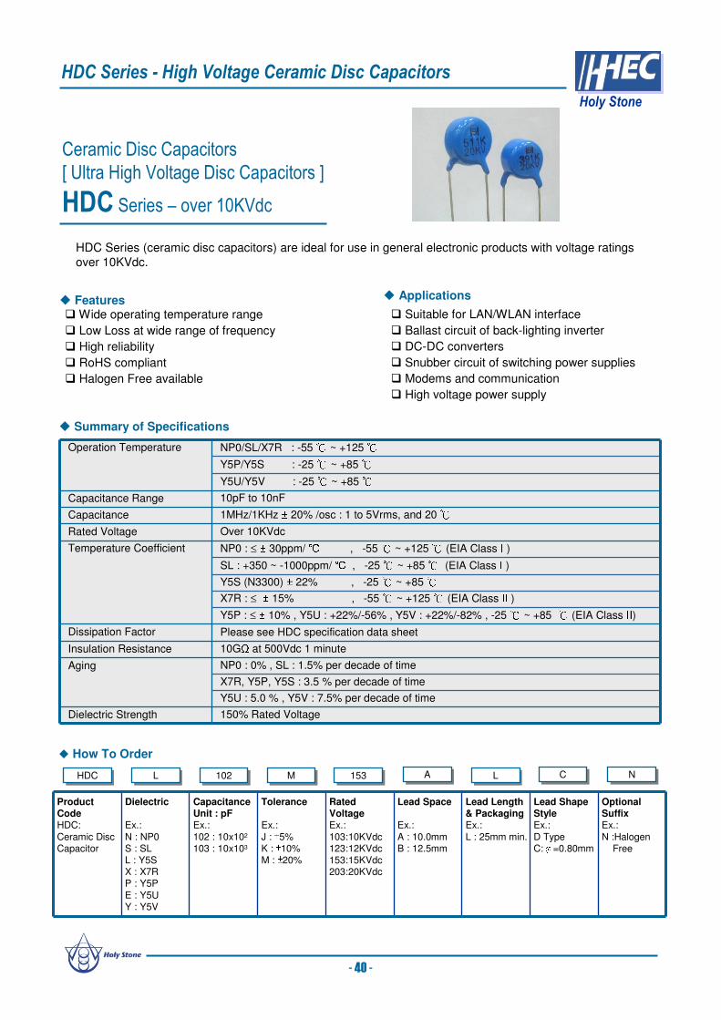
Suitable for LAN/WLAN interface
Ballast circuit of back-lighting inverter
DC-DC converters
Snubber circuit of switching power supplies
Modems and communication
High voltage power supply
Ceramic Disc Capacitors
[ Ultra High Voltage Disc Capacitors ]
HDC Series – over 10KVdc
How To Order
Summary of Specifications
Applications
HDCHDC LL 102102 MM 153153 AA LL CC
HDC Series (ceramic disc capacitors) are ideal for use in general electronic products with voltage ratings
over 10KVdc.
HDC Series - High Voltage Ceramic Disc Capacitors
Holy Stone
Features Wide operating temperature range
Low Loss at wide range of frequency
High reliability
RoHS compliant
Halogen Free available
Operation Temperature NP0/SL/X7R : -55 ~ +125Y5P/Y5S : -25 ~ +85Y5U/Y5V : -25 ~ +85
Capacitance Range 10pF to 10nF
Capacitance 1MHz/1KHz ± 20% /osc : 1 to 5Vrms, and 20Rated Voltage Over 10KVdc
Temperature Coefficient NP0 : ≤ ± 30ppm/ , -55 ~ +125 (EIA Class Ι )
SL : +350 ~ -1000ppm/ , -25 ~ +85 (EIA Class Ι )
Y5S (N3300) ± 22% , -25 ~ +85X7R : ≤ ± 15% , -55 ~ +125 (EIA Class Ⅱ )
Y5P : ≤ ± 10% , Y5U : +22%/-56% , Y5V : +22%/-82% , -25 ~ +85 (EIA Class Ⅱ)
Dissipation Factor Please see HDC specification data sheet
Insulation Resistance 10GΩ at 500Vdc 1 minute
Aging NP0 : 0% , SL : 1.5% per decade of time
X7R, Y5P, Y5S : 3.5 % per decade of time
Y5U : 5.0 % , Y5V : 7.5% per decade of time
Dielectric Strength 150% Rated Voltage
- 40 -
Product CodeHDC:
Ceramic DiscCapacitor
Dielectric
Ex.:
N : NP0S : SLL : Y5SX : X7RP : Y5P
E : Y5UY : Y5V
CapacitanceUnit : pFEx.:
102 : 10x102
103 : 10x103
Tolerance
Ex.:
J : ±5% K : ±10%M : ±20%
Rated VoltageEx.:
103:10KVdc123:12KVdc153:15KVdc203:20KVdc
Lead Space
Ex.:
A : 10.0mmB : 12.5mm
Lead Length & PackagingEx.:
L : 25mm min.
Lead Shape StyleEx.:
D TypeC:φ=0.80mm
Optional SuffixEx.:
N :HalogenFree
NN

100
120
150
180
220
270
330
390
470
560
680
820
101
121
151
181
221
271
331
391
471
561
681
821
102
152
222
332
472
682
103
123
Y5P
10KV
12KV
15KV
Capacitance Range
Y5U
Y5V
SL
10KV
12KV
NPO
Y5S
10KV
12KV
20KV
20KV
10KV
15KV
Dielectric
CharacteristicVoltage
10KV
15KV
12KV
15KV
15KV
10KV
15KV
X7R
10KV
12KV
15KV
Capacitance Range
Other capacitance and voltage rating are available. Please contact Holy Stone.
HDC Series - High Voltage Ceramic Disc Capacitors
Holy Stone
Dimensions
Temperature Capacitance Coefficient & DC Bias ( Typical Reference)
TD
F
G L
DR
D Type
CodeDimension
D Type
D Please contact Holy Stone
F 10.0±2 mm 12.5±2 mm
G 0.8±0.1mm max.
T Please contact Holy Stone
DR 5.0mm max.
Y5S Temperature Capacitance Coefficient
-40.0
-30.0
-20.0
-10.0
0.0
10.0
20.0
30.0
-30 -20 -10 0 10 20 30 40 50 60 70 80 90
Temperature
dC
/C
(%)
Y5S DC Bias Characteristic
-40
-30
-20
-10
0
10
0 1 2 3 4 5 6 7 8 9 10
DC Bias Voltage (KVDC)
dC
/C (%
)
- 41 -
s102M12KV

HDC Series - High Voltage Ceramic Disc Capacitors
Holy Stone
-42 -
(1) Operating Voltage:
When DC-rated capacitors are to be used in AC or ripple current circuits, be sure to maintain the Vp-p
value of the applied voltage or the Vo-p which contains a DC bias within the rated voltage range.
When the voltage is applied to the circuit, starting or stopping may generate an irregular voltage for a transit
period because of resonance or switching. Be sure to use a capacitor with a rated voltage range that
includes these irregular voltages.
(2) Operating Temperature and Self-generated Heat
Keep the surface temperature of a capacitor below the upper limit of its rated operating temperature range.
Be sure to take into account the heat generated by the capacitor itself. When the capacitor is used in a high
frequency current, pulse current or similar current, it may self-generate heat due to dielectric loss. The
frequency of the applied sine wave voltage should be less than 100kHz. The applied voltage load should
be such that the capacitor's self-generated heat is within 20°C at an atmosphere temperature of 25°C. When
measuring, use a thermocouple of small thermal capacity-K of ø0.1mm in conditions where the capacitor is
not affected by radiant heat from other components or surrounding ambient fluctuations.
Excessive heat may lead to deterioration of the capacitor's characteristics and reliability. (Never attempt to
perform measurement with the cooling fan running. Otherwise, accurate measurement cannot be ensured.)
(3) Fail-Safe
It should be assumed that if the capacitor fails, it will fail in short circuit mode. Be sure to provide an
appropriate fail-safe function, like a fuse in your circuit, if failure would cause an electric shock, fire or fumes.
(4) Operating and storage environment
The insulating coating of capacitors does not form a perfect seal; therefore, do not use or store capacitors
in a corrosive atmosphere, especially where chloride gas, sulfide gas, acid, alkali, salt or the like are
present, and avoid exposure to moisture. Before cleaning, bonding or molding this product, verify that these
processes do not affect product quality by testing the performance of a cleaned, bonded or molded product
in the intended equipment. Store the capacitors where the temperature and relative humidity do not
exceed –10 to 40 degrees centigrade and 15 to 85 %.
Use capacitors within 6 months.
(5) Vibration and impact
Do not expose a capacitor or its leads to excessive shock or vibration during use.
Caution

HDC Series - High Voltage Ceramic Disc Capacitors
Holy Stone
-43 -
(6) Soldering
When soldering this product to a PCB/PWB, do not exceed the solder heat resistance specification of the
capacitor.
Subjecting this product to excessive heating could melt the internal solder joint and may result in
thermal shock that can crack the ceramic element. When soldering capacitors with a soldering iron, it
should be performed in following conditions.
Temperature of iron-tip: 400 degrees C. max.
Soldering iron wattage : 50W max.
Soldering time : 3.5 sec. max.
(7) Cleaning (ultrasonic cleaning)
To perform ultrasonic cleaning, observe the following conditions.
Rinse bath capacity : Output of 20 watts per liter or less.
Rinsing time : 5 min. maximum.
Do not vibrate the PCB/PWB directly.
Excessive ultrasonic cleaning may lead to fatigue failure of the lead wires.
(8) Rating
Capacitance change of capacitor
(a). Class 1 series (Temp. Char. SL、NP0)
Capacitance might change a little depending on the surrounding temperature or an applied voltage.
Please contact us if you intend to use this product in a strict time constant circuit.
(b). CLASS 2 Series (Temp. Char. X7R,Y5S,Y5P,Y5U and Y5V)
Capacitors have an aging characteristic, whereby the capacitor continually decreases its capacitance
slightly if the capacitor is left on for a long time. Moreover, capacitance might change greatly
depending on the surrounding temperature or an applied voltage. Therefore, it is not likely to be
suitable for use in a time constant circuit.
Please contact us if you need detailed information.
Failure to follow the above cautions may result, in worst case, in short circuit and cause fuming or partial dispersion when the product is used.

Ceramic Disc Capacitors
[ Safety Disc Capacitors – X1Y1& X1Y2]
SDC Series
Features
Related Standards and Certificate Numbers
SDCSDC PP 101101 KK 5050 22 77
Product
CodeSDC:Safety DiscCeramic
Capacitor
Dielectric
Ex.:N : NP0S : SL
X : X7RP : Y5PY : Y5VE : Y5U
Capacitance
Unit : pFEx.:100 : 10x100
151 : 15x101
Tolerance
Ex.:J : ±5.0%K : ±10%
M : ±20%
Class
Ex.:10 : X1/Y150 : X1/Y2
Rated
VoltageEx.:2:Y Cap:250V
X Cap:400V
3:Y Cap:250VX Cap:440V
4:Y Cap:400VX Cap:440V
Lead Space
Ex.:5 : 5.00mm6 : 6.35mm
7 : 7.50mmA : 10.0mmB : 12.5mm
Lead Length
Ex.:H: 3.1mmC: 3.5mm
S: 5.0mmM: 10mmL : 25mm minT : T&RA: Ammo Box
Lead Shape
S Type1:φ=0.50mm2:φ=0.60mm3:φ=0.65mm
4:φ=0.80mmK Type5:φ=0.50mm6:φ=0.60mm7:φ=0.65mm
8:φ=0.80mmD Type9:φ=0.50mmA:φ=0.60mmB:φ=0.65mm
C:φ=0.80mm
How To Order
AA 22
This specification applies to the following Safety Standards that are recognized for Ceramic Capacitors
used in Electronic Appliances.
SDC Series - Safety Disc Capacitors
Holy Stone
Operating temperature range guaranteed up
to 125(UL/CSA:85)
Safety capacitors specially designed for use
in Modem, Facsimile, Telephone and other
electronic equipment for lighting and surge
protection, EMI filter and isolation.
The series is recognized by U/L,CSA,TUV,CCC
Coated with Flame-retardant epoxy resin
(conforming to UL 94-0 standards)
Suitable for automatic insertion
RoHS compliant
Halogen Free available
Applications
Safety capacitors specially designed for use
in Modem, Facsimile, Telephone and other
electronic equipment for lighting and surgeprotection, EMI filter and isolation.
Interference suppressor for AC line of
electronic equipment
- 44 -
Certificated Body Relation Standard Number Rated VoltageTUV IEC 60384-14 : 2005 (3nd Edition) EN 60384-14 : 2005EN 132400 :1994+A2:1998+A3:1998+A4:2001 R50152938 X1:400 VAC Y2:250 VACX1:440 VAC Y1:250 VACX1:440 VAC Y2:400 VACUL UL 1414Edition 5 E300818 SDC-Y2 250 VACSDC-Y1L 250 VACSDC-Y1H 250 VACCUL/CSA CSA :C22.2 No.1 E300818/1686156 250 VACENEC Report EN 60384-14 : 2005(3nd Edition) 2792364CB Report EN 60384-14 : 2005(3nd Edition) HU-455/A1

2R
0
3R
0
5R
0
8R
0
100
150
220
330
390
470
680
101
121
151
181
221
271
331
391
471
561
681
102
152
182
202
222
332
392
472
682
822
103
8/5 8/5 8/5 9/5 10 /5
8 /5 8 /5 8 /5 8/5 8/5 8/5 8/5 8/5
8/5 8/5 8/5 8/5 8/5 8/5 8/5 8/5 8/7 8 /7 8 /7 8 /7 8 /7 8 /7 8 /7 8 /7 8 /7 9 /7 9 /7 10 /7
8 /7 9 /7 10 /7 10 /7 10 /7 12 /7 13 /7 14 /710 /7
8 /7 8 /7 9 /7 10 /7 12 /7 14 /7 15 /7 16 /7
8 /8 8 /8 8 /8
8 /8 8/8 8/8 9/8 9/8 9/8 9/8 10 /8
8 /8 8 /8 8 /8 9 /8 9/8 9/8 10 /8 12 /8
8 /8 9 /8 10 /8 10 /8 11/8 13 .5 /8 14 .5 /8 15 .5 /8
8 /8 8 /8 8 /8
8/8 8/8 8/8 9/8 9/8 9/8 9/8 10 /8
8 /8 8 /8 8 /8 9 /8 9/8 9/8 10 /8 12 /8
8 /8 9 /8 10 /8 10 /8 11/8 13 .5 /8 14 .5 /8 15 .5 /8
Y5U
Class TC
X1: 400VAC
Y2: 250VAC
NPO
SL
Y5P
Y5U
Y5V
Capacitance Range
X1: 440VAC
Y1: 400VAC
NPO
SL
Y5P
Y5U
X1: 440VAC
Y1: 250VAC
NPO
SL
Y5P
P -Y2 250VAC
0
0.1
0.2
0.3
0.4
0.5
0.6
0.7
0 500 1000 1500 2000 2500 3000Vrms
lea
ka
ge
cu
rre
nt(
mA
)
E/Y - Y2 250VAC
0.0
0.5
1.0
1.5
2.0
2.5
3.0
3.5
4.0
0 500 1000 1500 2000 2500 3000Vrms
lea
ka
ge
cu
rre
nt(
mA
)
Capacitance Range
Dimensions
Summary of Specifications
SDC Series - Safety Disc Capacitors
Holy Stone
TD
F
G L
DR
D TypeS Type
TD
F
G L
DR
D
F
G
L
DR
5.0
ma
x.
T
K Type Code DimensionD Φ16.0mm max.F 5.0±1.0 mm 7.50±1.5 mm 10.0±2.0
mm
12.5±2.0 mmG 0.5±0.1mm / 0.6±0.1mm / 0.8±0.1mmT 8.0mm max.DR 4.0mm max.
Operation Temperature -25 ~ +125 Dielectric Strength
X1:440 VAC / Y1:250 VAC : 4000VAC for 1 minute
X1:440 VAC / Y1:400 VAC : 4000VAC for 1 minute
X1:400 VAC / Y2:250 VAC : 2600VAC for 1 minute
Capacitance Range
X1:440 VAC / Y1:250 VAC : 2pF to 4700pF
X1:440 VAC / Y1:400 VAC : 2pF to 4700pF
X1:400 VAC / Y2:250 VAC : 2pF to 10,000pF
Dissipation Factor
Class I , NP0/SL : Q ≥ 300 at 1MHz/1Vrms
Class II , Y5P : DF ≤ 2.5% , Y5U/Y5V : DF ≤ 5.0% at 1KHz/1Vrms
Insulation Resistance 10,000MΩ min. at 500Vdc
Body Diameter (max.) / Body Thickness (max.)
Leakage Current Characteristics ( Typical Reference)
SDCP101K502*
SDCP221K502*
SDCP471K502*
SDCE102M502*
SDCE222M502*
SDCE472M502*
SDCY103M502*
- 45 -
s s s

Caution (Rating)
SDC Series - Safety Disc Capacitors
Holy Stone
-46 -
(1) Operating Voltage
Be sure to maintain the Vp-p value of the applied voltage or the Vo-p which contains a DC bias
within the rated voltage range.
When the voltage is started to apply to the circuit or it is stopped applying, the irregular voltage
may be generated for a transit period because of resonance or switching. Be sure to use a capacitor
within rated voltage containing this irregular voltage.
(2) Operating Temperature and Self-generated Heat
Keep the surface temperature of a capacitor below the upper limit of its rated operating
temperature range. Be sure to take into account the heat generated by the capacitor itself. When the
capacitor is used in a high-frequency current, pulse current or the like, it may have the
self-generated heat due to dielectric-loss.
Applied voltage should be the load such as self-generated heat is within 20 on the condition of
atmosphere temperature 25. When measuring, use a thermocouple of small thermal capacity-K
of φ0.1mm and be in the condition where capacitor is not affected by radiant heat of other
components and wind of surroundings. Excessive heat my lead to deterioration of the capacitor’s
characteristics and reliability.
(3) Test condition for withstanding Voltage
I. Test Equipment
Test equipment for AC withstanding voltage shall be used with the performance of the wave
similar to 50/60 Hz sine waves.
If a distorted sine wave or over load exceeding the specified voltage value is applied, a
failure may be caused.
II. Voltage Applied Method
When the withstand voltage is applied, the capacitor’s leads or terminals shall be firmly
connected to the output of the withstand voltage test equipment, and then the voltage shall
be raised from near zero to the test voltage.
If the test voltage is applied directly to capacitor, the test voltage should be applied at the *zero cross
point. At the end of the test time, the test voltage shall be reduced to near zero, and then capacitor's
lead or terminal shall be taken off the output of the withstand voltage test equipment.
If the test voltage is not applied from the near zero voltage point and applied directly to
capacitor, a surge voltage may arise, and cause the capacitor to fail.
* ZERO CROSS is the point where voltage sine wave
pass 0V.- See the right figure.
(4) Fail-Safe
It should be assumed that if the capacitor fails, it will fail in short circuit mode. Be sure to provide an
appropriate fail-safe function, like a fuse in your circuit, if failure would cause an electric shock, fire or
fumes.
SDC Series - Safety Disc Capacitors
Holy Stone
-47 -
Caution (Storage and operating condition)
The insulating coating of capacitors does not form a perfect seal; therefore, do not use or store
capacitors in a corrosive atmosphere, especially where chloride gas, sulfide gas, acid, alkali, salt
are likely to be present. And avoid exposure to moisture. Before cleaning, bonding, or molding this
product, verify that these processes do not affect product quality by testing the performance of a
cleaned, bonded or molded product in the intended equipment. Store the capacitors where the
temperature and relative humidity do not exceed –10 to 40 degrees centigrade and 15 to 85 % R.H.
Use capacitors within 6 months.
Caution (Soldering and Mounting)
1. Vibration and impact:
Do not expose a capacitor or its leads to excessive shock or vibration during use.
2. Soldering:
When soldering this product to a PCB/PWB, do not exceed the solder heat resistance specification of
the capacitor. Subjecting this product to excessive heating could melt the internal junction solder and
may result in thermal shocks that can crack the ceramic element.
When soldering these capacitor with a soldering iron, it should be performed in following conditions.
3. Cleaning (ultrasonic cleaning):
To perform ultrasonic cleaning, observe the following conditions.
Rinse bath capacity: Output of 20 watts per liter or less.
Rinsing time: 5 min maximum.
Do not vibrate the PCB/PWB directly.
Excessive ultrasonic cleaning may lead to fatigue destruction of the lead wires.
Temperature of iron-tip: 400 degrees C. max.
Soldering iron wattage: 50W max.
Soldering time: 3.5 sec. max.
Caution (Handling)
Vibration and impact
Do not expose a capacitor or its leads to excessive shock or vibration during use.
Failure to follow the above cautions may result, in worst case, in a short circuit and cause fuming or partial dispersion where the product is used.

Standard packing 10Kpcs/pack, others according to customers’ request.
Bulk Packing
Paper Tape Embossed Tape
Embossed Carrier Tape
Top Cover Tape
Bottom Cover Tape
Carrier Tape
Top Cover Tape
Tape Packing
Empty Section
20mm min.
Empty Section
40mm min. Chip Section
400mm min.Drawing Direction
NA:Not Available
Material And Quantity (¢180mm)
0201 0.6 0.3 T≤0.33 15,000 pcs/reel N/A
0402 1.0 0.5 T≤0.55 10,000 pcs/reel N/A
0603 1.6 0.8 T≤0.90 4,000 pcs/reel N/A
0805 2.0 1.25 T≤0.90 4,000 pcs/reel N/A
0.9< T≤1.25 N/A 3,000 pcs/reel
1206 3.2 1.6 T≤0.90 4,000 pcs/reel N/A
0.9< T≤1.25 N/A 3,000 pcs/reel
T>1.25 N/A 2,000 pcs/reel
1210 3.2 2.5 T≤1.25 N/A 3,000 pcs/reel
T>1.25 N/A 2,000 pcs/reel
1808 4.6 2.0 T≤1.25 N/A 3,000 pcs/reel
T>1.25 N/A 2,000 pcs/reel
1812 4.6 3.2 T≤2.20 N/A 1,000 pcs/reel
T>2.20 N/A 700 pcs/reel
1825 4.6 6.35 T≤2.20 N/A 700 pcs/reel
T>2.20 N/A 400 pcs/reel
2208 5.7 2.0 T≤2.20 N/A 1,000 pcs/reel
2211 5.7 2.8 T≤2.20 N/A 1,000 pcs/reel
T>2.20 N/A 700 pcs/reel
2220 5.7 5.0 T≤2.20 N/A 1,000 pcs/reel
T>2.20 N/A 700 pcs/reel
2225 5.7 6.35 T≤2.20 N/A 700 pcs/reel
T>2.20 N/A 400 pcs/reel
Chip Size Dimension (mm) ¢180mm reel
(EIA Code) L W T Paper Tape Plastic Tape
Multilayer Ceramic Chip Capacitor
Packing Information
Holy Stone
-48 -
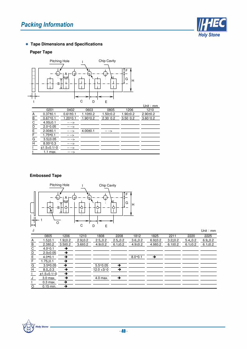
t C D E
HG
FA
B
Pitching Hole I Chip Cavity
Tape Dimensions and Specifications
Paper Tape
0201 0402 0603 0805 1206 1210
A 0.37±0.1 0.61±0.1 1.10±0.2 1.50±0.2 1.90±0.2 2.90±0.2
B 0.67±0.1 1.20±0.1 1.90±0.2 2.30±0.2 3.50±0.2 3.60±0.2
C 4.00±0.1 -- -->
D 2.0±0.05 -- -->
E 2.00±0.1 -- --> 4.00±0.1 -- -->
F 1.75±0.1 -- -->
G 3.5±0.05 -- -->
H 8.00±0.3 -- -->
I ¢1.5+0.1/-0 -- -->
t 1.1 max. -- -->
Unit:mm
C D E
HG
FA
B
Pitching Hole I Chip Cavity
Ot
J
Embossed Tape
Unit:mm
0805 1206 1210 1808 2208 1812 1825 2211 2220 2225
A 1.5±0.1 1.9±0.2 2.9±0.2 2.5±0.2 2.5±0.2 3.6±0.2 6.9±0.2 3.2±0.2 5.4±0.2 6.9±0.2
B 2.3±0.2 3.5±0.2 3.6±0.2 4.9±0.2 6.1±0.2 4.9±0.2 4.9±0.2 6.1±0.2 6.1±0.2 6.1±0.2
C 4.0±0.1
D 2.0±0.05
E 4.0±0.1 8.0±0.1
F 1.75±0.1
G 3.5±0.05 5.5±0.05
H 8.0±0.3 12.0 +3/-0
I ¢1.5+0.1/-0
J 3.0 max. 4.0 max.
t 0.3 max.
O 0.15 min.
Packing Information
Holy Stone
- 49 -

Reel Dimensions
r D
E
C
AW t
B
Unit:mm
0402 to 1210 1808 to 2220
A ¢ 382 max. ¢ 178±0.2
B ¢ 50 min. ¢ 60±0.2
C ¢ 13±0.5 ¢ 13±0.5
D ¢ 21±0.8 ¢ 21±0.8
E ¢ 2.0±0.5 ¢ 2.0±0.5
W 10±0.15 13±0.3
t 2.0±0.5 17±1.4
r 1.0 1.0
Bulk Cassette Packing19.0mm
5.0mm
6.8±0.1mm8.8±0.1mm12.0
±0.1mm10mm
53.3mm
1.5 mm +0.1-0
2.0 mm +0-0.1
3.0 mm +0.2-0
36.0 mm
+0-0.2
31.5 mm
+0.2
-0
110±0.7 mm 165 to 180°
Top Tape
Bottom Tape
The peel force of cover tape is 5 to 70 grams in the direction of arrow.
Cover Tape Peel Force
Packing Information
Holy Stone
Chip Size 0402 0603 2012
Cassette Packing
Length 1.00±0.05 1.60±0.10 2.00±0.20
Width 0.50±0.05 0.80±0.10 1.25±0.20
Thickness 0.50±0.05 0.80±0.10 0.60±0.10
Quantity 50,000pcs 15,000pcs 10,000pcs
Unit:mm
- 50 -

Standard packing 300pcs,500pcs&1,000pcs/pack, others according to customers’ request. Bulk Packing
Tape Packing
Ceramic Disc Capacitors Packing Information (SDC,HDC Series)
P0
P1
ψD0
W0W1
W
H0
P
ΔL
DΔh Δh
t1
t2
Symbol Lead Space
5.00mm 6.35mm 7.50mm
Pitch of component P 12.7±1.0
Feed Hole Pitch P0 12.7±0.3
Hole center to component center P1 6.35±1.3
Body diameter D 11.0 max
Hold position W1 8+1.0-0.5
Hold tape width W0 10 min
Hold position W1 9±0.5
Lead wire clinch H0 16+1.5-0.5
Total tape thickness t1 0.6±0.3
Total thickness, tape& lead wire t2 1.5 max
Feed hold diameter ψD0 4.0±0.2
Deviation across tape h 2.0 max
Protrusion Length L 1.0 max
Unit:mm
Packing Dimensions
Unit:mm
Code DimensionW1 56W 44
D 340 A 30B 84
Packing Quantity
Package One Box / One Reel Carton Box
Taping Reel Pack 1,500 / 2,000 pcs 15,000 / 20,000 pcs
Ammo Box Pack 1,000 / 1,500 pcs 10,000 / 15,000 pcs
Unit:mm
A
B
W
D W1
Reel Dimensions : Ammo Dimensions :
330±5mm
253
±5mm
48±3mm
Packing Information
Holy Stone
- 51 -
Bulk Package Lead Code Qt’y/One Pack
HDC Series H,C,S,M / L 1,000 / 500 pcs
SDC Series H,C,S,M / L 500 / 250 pcs

The Multilayer Ceramic Chip of Capacitors supplied in bulk, cassette or taped & reel package are
ideally suitable for thick-film Hybrid circuits and automatic surface mounting on printed circuit boards.
Mainly use in electric circuit for by-pass, filtering and smoothing circuit.
W
T
L
BW B
Solder Metal
Barrier
External Electrodes
Inner Electrodes
Shapes and Dimensions
Nominal Capacitance and Tolerance
Class EIA Tolerance Nominal CapacitorSymbolΙ NP0 J (±5%),K (±10%) E-12 ,E-24 SeriesΠ X7R K(±10%), M(±20%) E-3,E-6 Series
X7E K(±10%), M(±20%) E-3,E-6 Series
X5R K(±10%), M(±20%) E-3,E-6 Series
Y5U M(±20%),Z(+80/-20 %) E-3 Series
Y5V M(±20%),Z(+80/-20 %) E-3 Series
Z5U M(±20%),Z(+80/-20 %) E-3 Series
1. Standard Combination of Nominal Capacitance and Tolerance 2. E Series (Standard Number)
E- Application CapacitanceSeries
E-3 1.0 2.2 4.7
E-6 1.0 1.5 2.2 3.3 4.7 6.8
E12 1.0 1.2 1.5 1.8 2.2 2.7 3.3 3.9 4.7 5.6 6.8 8.2
E24 1.0 1.2 1.5 1.8 2.2 2.7 3.3 3.9 4.7 5.6 6.8 8.2
1.1 1.3 1.6 2.0 2.4 3.0 3.6 4.3 5.1 6.2 7.5 9.1
C : Capacitanceε0 : Dielectric constant in the airε : Proportional dielectric constantA : Overlap Areat : Dielectric ThicknessN : Layers
t
A
C1
C2
C3
C4
C =· NA
tε0 ·ε
Cross Section
Dimensions(mm) [inches]
EIA style L W Tmax. BWmin Bmin.
0201 0.60±0.03 0.30±0.03 0.33 0.10 0.20[.024±.002] [.011±.002] [.013] [.004] [.008]
0402 1.00±0.05 0.50±0.05 0.55 0.15 0.30[.039±.002] [.020±.002] [.022] [.006] [.012]
0603 1.60±0.10 0.80±0.10 0.95 0.15 0.40[.063±.004] [.031±.004] [.037] [.006] [.016]
0805 2.00±0.20 1.25±0.20 1.45 0.20 0.70[.079±.008] [.049±.008] [.057] [.008] [.028]
1206 3.20±0.30 1.60±0.20 1.80 0.30 1.50 [.126±.012] [.063±.008] [.071] [.012] [.059]
1210 3.20±0.30 2.50±0.20 2.60 0.30 1.60[.126±.012] [.098±.008] [.102] [.012] [.063]
1808 4.60±0.30 2.00±0.20 2.20 0.30 2.50[.181±.012] [.079±.008] [.087] [.012] [.098]
1812 4.60±0.30 3.20±0.30 3.00 0.30 2.50[.181±.012] [.126±.012] [.118] [.012] [.098]
1825 4.60±0.30 6.35±0.40 2.60 0.30 2.50[.181±.012] [.250±.016] [.102] [.012] [.098]
2208 5.70±0.40 2.00±0.20 2.20 0.30 3.50[.220±.016] [.197±.008] [.087] [.012] [.137]
2211 5.70±0.40 2.80±0.40 3.00 0.30 3.50[.220±.016] [.110±.016] [.118] [.012] [.137]
2220 5.70±0.40 5.00±0.40 3.00 0.30 3.50[.220±.016] [.197±.016] [.118] [.012] [.137]
2225 5.70±0.40 6.35±0.40 3.00 0.30 3.50[.220±.016] [.250±.016] [.118] [.012] [.137]
- 52 -
General Introduction
Holy Stone

Operating Temperature Range
Class EIA Symbol Dielectric Code Temperature Range() Capacitance Change Reference TemperatureΙ NP0 N -55 ~ +125 0±30 ppm/ 25SL L -25 ~ +85 +350/-1000 ppm/ 25Π X7R X -55 ~ +125 ±15% 25X7E C -55 ~ +125 ±4.7% 25X5R B -55 ~ +85 ±15% 25Y5V Y -30 ~ +85 +22/-82 % 25Y5U E -30 ~ +85 +22/-56 % 25Z5U Z +10 ~ +85 +22/-56 % 25
EIA Designations
Low Temp. Symbol
High Temp. Symbol
Max. %C Symbol
-55 X
-30 Y
+10 Z
+45 3
+65 4
+85 5
+105 6
+125 7
+150 8
+200 9
±1.0% A±1.2% B±2.2% C±3.3% D±4.7% E±7.5% F±10.0% P±15.0% R±22.0% S
+22% /-33% T
+22% /-56% U
+22% /-82% V
Aging Rate
NP0: 0
X7R/X5R : 1 ~ 4 % /decade
Y5U/Z5U : 4~6% / decate
Y5V : 6~10 % /decade
Dielectric Material – Aging Rate
After performing De-Aging at 150±5 for 30 minutes andplacement at room temperature for 48 hours.
Aging Rate
-18
-16
-14
-12
-10
-8
-6
-4
-2
0
2
1 10 100 1000hour
C/C( %)
X5R/X7R
Y5V
NP0
0(48Hr)
Y5U/Z5U
Coefficient of capacitance (ppm/ )
Multiplier applicable to column
Tolerance of temp. coeff.(ppm/ )
0.0 C
1.0 M
1.5 P
2.2 R
3.3 S
4.7 T
7.5 U
-1.0 0
-10 1
-100 2
-1000 3
-10000 4
+1 5
+10 6
+100 7
+1000 8
+10000 9
30 G
60 H
120 J
250 K
500 L
1000 M
2500 N
For Class Π DielectricsFor Class ΙDielectrics
Ex.: C0G Negative 0±30ppm/ U2J Negative 750±120ppm/ Ex.: X7R -55 ~ +125 ±15%
Y5V -30 ~ +85 +22%/-82%
General Introduction
Holy Stone
- 53 -

Improper circuit layout and pad/land size may cause poor solder joints between the component and the
PC board. Insufficient solder may create a weak joint, and excessive solder may increase the potential for
mechanical or thermal cracks in the ceramic capacitor. Therefore we recommend the solder pad/land size
to be as shown in the following table:
1. Size and recommend land dimensions for reflow soldering
EIA CodeChip (mm) Land (mm)
L W A B C D E0201 0.60 0.30 0.2~0.3 0.2~0.4 0.2~0.4 -- --
0402 1.00 0.50 0.3~0.5 0.3~0.5 0.4~0.6 -- --0603 1.60 0.80 0.4~0.6 0.6~0.7 0.6~0.8 -- --0805 2.00 1.25 0.7~0.9 0.6~0.8 0.8~1.1 -- --1206 3.20 1.60 2.2~2.4 0.8~0.9 1.0~1.4 1.0~2.0 3.2~3.71210 3.20 2.50 2.2~2.4 1.0~1.2 1.8~2.3 1.0~2.0 4.1~4.6
1808 4.60 2.00 2.8~3.4 1.8~2.0 1.5~1.8 1.0~2.8 3.6~4.11812 4.60 3.20 2.8~3.4 1.8~2.0 2.3~3.0 1.0~2.8 4.8~5.31825 4.60 6.35 2.8~3.4 1.8~2.0 5.1~5.8 1.0~4.0 7.1~8.32208 5.70 2.00 4.0~4.6 2.0~2.2 1.5~1.8 1.0~4.0 3.6~4.12211 5.70 2.80 4.0~4.6 2.0~2.2 2.0~2.6 1.0~4.0 4.4~4.9
2220 5.70 5.00 4.0~4.6 2.0~2.2 3.5~4.8 1.0~4.0 6.6~7.12225 5.70 6.35 4.0~4.6 2.0~2.2 5.1~5.8 1.0~4.0 7.1~8.3
2. Mechanical strength varies according to location of chip capacitors on the P.C. board.
Design the layout of components on the PC board in such a way to minimize the stress imposed on
the components, upon flexure of the boards in depanelization or other processes.
Component layout close to the edge of the board or the
“depanelization line” is not recommended.
Susceptibility to stress is in the order of: a>b>c and d>e
a
c
b
d
slitperforation
e
In the pick and place operation, if the low dead point is too low, excessive stress is applied to
component. This may cause cracks in the ceramic capacitor, therefore it is required to move the low
dead point of the nozzle to the higher level to minimize the board warpage and stress on the
components. Nozzle pressure should be adjusted to N to 3N (static load) during the pick and place
operation.
1. Sometimes cracking can be caused by the impact load of the pick and place nozzle.
Nozzle
Crack
Excessive Stress Warping of Board
PCB
Warping of Board
Support pin
2. Amount of Adhesive a a
b
c c
Example : 0805 & 1206
Construction of Board Pattern
Mounting
E
Land
A
Solder Resistor
C
B
Capacitor
D
Slit
Precautionary Information
Holy Stone
a 0.2mm min.
b 70 ~ 100 μm
c Do not touch the solder land
- 54 -

Handling after chip mounted
1. Proper handling of the PCB is recommended since excessive bending and twisting of the PC board may
induce mechanical stress and cause internal cracking of the capacitor.
2. There is a potential of cracking if board is warped due to excessive load from the
check pin
Check pinCheck pin
Support Pin
3. Examples of PCB de-panelization jigs:
Higher potential of crack Lower potential of crack
Bending
Twist
V-groove
PCB splitting jig
PCB
The outline of PCB breaking jig is shown below. It is recommended when dividing or breaking PCB
that they are held near the jig where no bending will occur, this way there will be no compressive stress
is applied to the capacitors on the PCB. Do not hold the PCB at a position which is far away from the jig,
tensile stress to the capacitors may cause them to crack.
Poor Dividing
Load DirectionLoad Direction
PCB
V-groove
Chip Component
Recommend Dividing
Load Direction
Load Direction
Chip Component
Precautionary Information
Holy Stone
- 55 -

1. Wave Soldering
Recommend flow soldering temperature Profile
Soldering
Most components are wave soldered with solder at 230 to 250°C. Adequate care must be taken to
prevent the potential of thermal cracks in the ceramic capacitors. Refer to the soldering methods below
for optimum soldering benefits.
Soldering Method Change in Temp.()
1206 and Under ∆T ≤100~130max.
To optimize the result of soldering, proper preheating is essential:
1) Preheat temperature is too low
a. Flux flows to easily
b. Possibility of thermal cracks
2) Preheat temperature is too high
a. Flux deteriorates even when oxide film is removed
b. Causes warping of circuit board
c. Loss of reliability in chip and other components
2. Reflow Soldering
Preheat to the reflow temperature is recommended to decrease the potential of thermal cracking in the
components. The recommended heating rate depends on the size of component, however it should not
exceed 3°C/Sec.
Recommend reflow profile for Lead-Free soldering temperature Profile (MIL-STD-202G #210F)
Soldering Method Change in Temp.()
1206 and Under ∆T ≤1901210 and Over ∆T ≤130
Cooling Condition:
Natural cooling in air is recommended. Forced cooling should be avoided, however if the chips are
dipped into a solvent for cleaning, the temperature difference (ΔT ) between the solvent and the chips
must be less than 100°C.
Tem
pera
ture
(°C
)
217
260max.
150°C /60sec. Min. 70 to 90 sec.
Pre-heatingSoldering
Cooling
∆T
260 °C max./ 10 sec.
120seconds or more2 to 3 sec.
60seconds or more
∆T
Tem
pera
ture
(°C
)
200
250
300
Pre-heatingSoldering
Cooling
230
※※※※ The cycles of soldering : Twice (Max.)
Precautionary Information
Holy Stone
- 56 -

How to Solder Repair by Solder Iron
1) Selection of the soldering iron tip
The required temperature of soldering iron for any type of repair depends on the type of the tip, the
substrate material, and the solder land size.
2) recommended solder iron condition
a.) Preheat the substrate to (60°C to 120°C) on a hot plate. Note that due to the heat loss,
the actual setting of the hot plate may have to be higher. (For example 100°C to 150°C)
b.) Soldering iron power shall not exceed 30 W.
c.) Soldering iron tip diameter shall not exceed 3mm. d.) Temperature of the iron tip shall not exceed 350°C, and the process should be finished
within 5 seconds. (refer to MIL-STD-202G)
e.) Do not touch the ceramic body with the tip of solder iron. Direct contact of the soldering iron tip
to ceramic body may cause thermal cracks.
f.) After soldering operation, let the products should be allowed to cool down naturally in air.
Store the capacitors where the temperature and relative humidity do not exceed 40°C and 70%RH.
We recommend that the capacitors be used within 12 months from the date of manufacturing. Store
the products in the original package and do not open the outer polyethylene bag until just before
usage. If it is open, seal it as soon as possible or keep it in a desiccant with a desiccation agent.
3. Hand Soldering
Sudden temperature changes in ceramic capacitors will result in a temperature gradient within the
component and therefore may cause internal thermal cracking. In general a hand soldering method is not
recommended unless proper preheating and handling practices have been taken. Care must also be
taken not to touch the ceramic body of the capacitor with the tip of solder Iron. The soldering iron tip
should always be placed on to the solder pad.
Soldering Method Change in Temp.()
1206 and Under ∆T ≤1501210 and Over ∆T ≤130
∆T
Tem
pera
ture
(°C
)
200
250
350
Within 5 seconds.
Storage
Precautionary Information
Holy Stone
- 57 -

Internal MLCC cracking
can result in serious
failure modes. If ceramic
capacitors are subjected
to severe mechanical
stress, a bending crack
may occur. This crack
can run through two or
more electrodes of
opposing polarity and
result in a short circuit.
Typical bending cracks
are shown below. In the
worst case scenario,
these short circuits may
lead to the MLCC
overheating and
catastrophic failure.
Bending
Ag/Cu
Plating-Sn
Plating-Ni
PCB
Solder
force
Crack
Typical Applications are power circuit input and output filtering, smoothing…
Standard termination construction may result in cracking during PCB bending, vibration, Depanelizing, etc.
CrackCrack running through at least two electrodes.
Surface View Cross Section View
Actual Examples:
Failure Mode Type 1
The failure mode results
from PCB bending forces.
These cracks may not be
visible on the MLCC
surface. Cross sectional
analysis is required to
determine these internal
cracks.
Failure Mode Type 2 (wetting greater than 2/3 of thickness)
Top View Cross Section View
MLCC cracking frequently
occurs during the circuit
board depanelizing
process. The root cause is
knife (blade) vibration
during the process.
CrackCrack
Reducing Short Circuit Risks – Super Term
Holy Stone
- 58 -
Super Term AdvantagesSuper Term AdvantagesSuper Term Advantages
•• ““FlexibleFlexible”” Termination Layer incorporatedTermination Layer incorporated
•• Reduce Cracking due to Mechanical Stress Reduce Cracking due to Mechanical Stress

Holy Stone has developed the “Super Term” Series (TX suffix in the part number), which
incorporates a “cushion layer” in the termination structure. This construction effectively absorbs external
forces, reduces the incidence of cracking and improves overall product reliability. Super Term product
applications include: high temperature automotive, power circuits and other critical end products with
extreme processing conditions.
Bending
Ag/Cu
Plating-SnPlating-Ni
PCB
Solder
Cushion Layer
force
Crack Prevention
TX Product
(a) Thermal Shock Comparison ( 0805/X7R)
Reliability/Durability Comparison
(b) Substrate Flexure Comparison ( 0805/X7R)Thermal Shock01020304050
1 10 100 1000 10000CyclesFailure Rate(%) Normal TX Series Flexure of Substrate0123456789Benging Capability (m
m) Normal TX SeriesThermal shock test on standard termination results in
inception of failure at 500 cycles. Super Term TX Series
reliability improves to over 3000 cycles.
Bending test on Super Term shows an improvement of
about 5.0 mm bend vs. an average of about 2.0 mm. for
standard termination.
Plating : Sn
Plating : Ni
Polymer Ag
Glass Ag
During destructive bending test,
the PCB is subjected to bending
until capacitor failure. With Super
Term there is no cracking damage
in the ceramic. Super Term
effectively prevents ceramic body
cracking during extreme
mechanical stress as simulated by
this test.
No cracking apparent in the ceramic
Super Term failures resulting from destructive bending test tend to occur in the OPEN mode and not
short circuit mode typical of standard termination failures. The Super Term cushion layer material is
a ”polymer silver” material and can be seen in the above photo.
Polymer Ag
Reducing Short Circuit Risks – Super Term
Holy Stone
- 59 -

MLCC Arc Prevention – for Hi-Pot Testing
Typical Applications for telecommunication devices(IEEE802.3) in LAN interface, Ballast…
Due to the open and porous nature of
the surface of the X7R dielectric,
moisture and/or dirt which will have a
lower resistance than the dielectric
grains, can become entrapped in the
surface. Dirt can also include any flux
residues as a result of the soldering
process. This dirt/flux as well as
becoming entrapped into the surface
will, in itself, attract additional moisture
onto the surface thus reducing the
surface resistance and the voltage at
which arcing occurs. Surface arcing or
flashover at worst can cause equipment
failure during isolation testing and, in
addition, will leave a carbon track on the
surface which can lead to eventual
failure of the capacitor.
Typical surface arcing on X7R MLCC is from termination-to-termination
(shown in polarized light)
NP0 & X7R Material Characteristic Comparison
ItemItem NP0NP0 X7RX7R
Dielectric ConstantDielectric Constant 30 ~ 10030 ~ 100 2000 ~ 40002000 ~ 4000
I. ResistanceI. Resistance >10>101313 ΩΩΩΩΩΩΩΩ >10>101111 ΩΩΩΩΩΩΩΩ
B.D. Voltage B.D. Voltage 70~80 70~80 VdcVdc/um/um 40~50 40~50 VdcVdc/um/um
Grain SizeGrain Size < 500nm< 500nm 900nm ~ 1500nm900nm ~ 1500nm
Grain SizeGrain Size
(x8000)(x8000)
Porosity Porosity
(x1000)(x1000)
• The different grain shape and size will lead to
different grain density after sintering.
• The grain size of NP0 dielectric is smaller than
that of X7R resulting a denser and less porous
structure.
•Surface porosity will trap dirt, flux and moisture
causing the surface resistance to dramatically
decrease.
• Low surface resistance will cause the arcing
voltage to reduce, possibly leading to failure of the
capacitor or equipment during isolation testing.
•Using the Holy Stone Arc Prevention coating
effectively makes the surface of X7R dielectric
similar to that of NP0.
Arc PreventionArc Prevention
Passed IEEE 802.3 1500VAC or 2250VDC
Increases
voltage at
which arcing
occurrs
Coated Products for Surface Arc Prevention
Holy Stone
- 60 -
Holy Stone has developed an Arc Prevention
coating process that coats the surface of the
dielectric without encroaching onto the termination
material. This coating makes the surface of the
dielectric non porous and prevents moisture and dirt
becoming trapped thus reducing the surface
resistance and the arcing voltage of the capacitor. It
has been shown that the arcing voltage can be
increased by up to 65% on soldered parts by using
the Holy Stone Arc Prevention Coating.
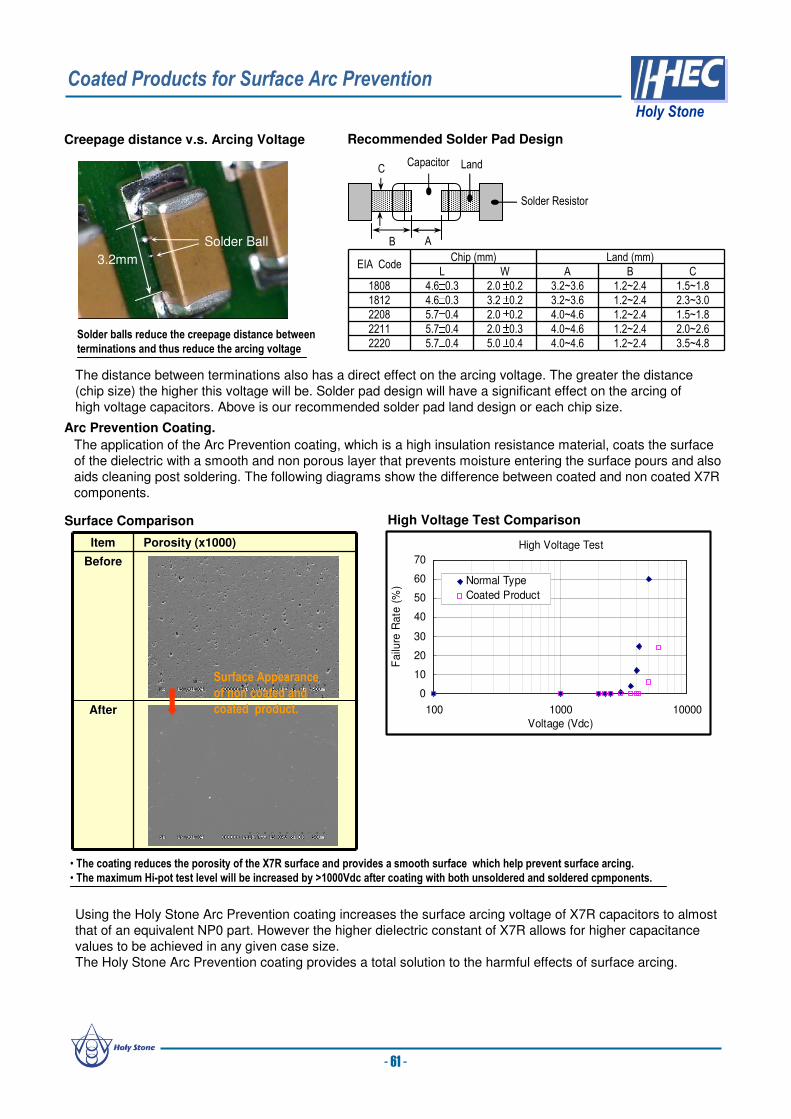
3.2mm
Solder Ball
Solder balls reduce the creepage distance between
terminations and thus reduce the arcing voltage
Creepage distance v.s. Arcing Voltage Recommended Solder Pad Design
Land
A
Solder Resistor
C
B
Capacitor
EIA CodeChip (mm) Land (mm)
L W A B C
1808 4.6±0.3 2.0 ±0.2 3.2~3.6 1.2~2.4 1.5~1.8
1812 4.6±0.3 3.2 ±0.2 3.2~3.6 1.2~2.4 2.3~3.0
2208 5.7±0.4 2.0 ±0.2 4.0~4.6 1.2~2.4 1.5~1.8
2211 5.7±0.4 2.0 ±0.3 4.0~4.6 1.2~2.4 2.0~2.6
2220 5.7±0.4 5.0 ±0.4 4.0~4.6 1.2~2.4 3.5~4.8
The distance between terminations also has a direct effect on the arcing voltage. The greater the distance
(chip size) the higher this voltage will be. Solder pad design will have a significant effect on the arcing of
high voltage capacitors. Above is our recommended solder pad land design or each chip size.
Arc Prevention Coating.
The application of the Arc Prevention coating, which is a high insulation resistance material, coats the surface
of the dielectric with a smooth and non porous layer that prevents moisture entering the surface pours and also
aids cleaning post soldering. The following diagrams show the difference between coated and non coated X7R
components.
ItemItem Porosity (x1000)Porosity (x1000)
BeforeBefore
AfterAfter
Surface Appearance
of non coated and
coated product.
Surface Comparison High Voltage Test Comparison
• The coating reduces the porosity of the X7R surface and provides a smooth surface which help prevent surface arcing.
• The maximum Hi-pot test level will be increased by >1000Vdc after coating with both unsoldered and soldered cpmponents.
Using the Holy Stone Arc Prevention coating increases the surface arcing voltage of X7R capacitors to almost
that of an equivalent NP0 part. However the higher dielectric constant of X7R allows for higher capacitance
values to be achieved in any given case size.
The Holy Stone Arc Prevention coating provides a total solution to the harmful effects of surface arcing.
High Voltage Test
0
10
20
30
40
50
60
70
100 1000 10000
Voltage (Vdc)
Fa
ilure
Ra
te (
%)
Normal Type
Coated Product
- 61 -
Coated Products for Surface Arc Prevention
Holy Stone
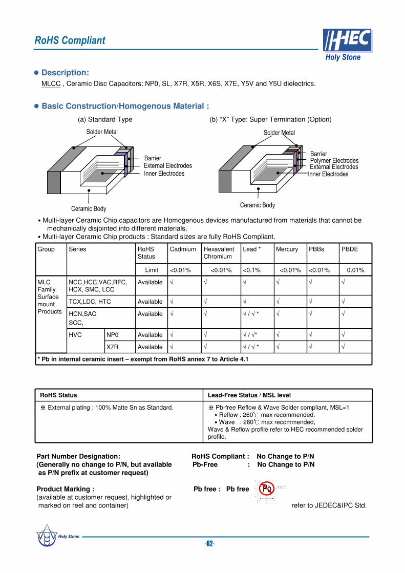
MLCC , Ceramic Disc Capacitors: NP0, SL, X7R, X5R, X6S, X7E, Y5V and Y5U dielectrics.
Description:
Basic Construction/Homogenous Material :
(a) Standard Type (b) “X” Type: Super Termination (Option)
External Electrodes
Barrier
Solder Metal
Inner Electrodes
Polymer ElectrodesExternal ElectrodesBarrier
Solder Metal
Inner Electrodes
Ceramic BodyCeramic Body․Multi-layer Ceramic Chip capacitors are Homogenous devices manufactured from materials that cannot be
mechanically disjointed into different materials.․Multi-layer Ceramic Chip products : Standard sizes are fully RoHS Compliant.
Group Series RoHSStatus
Cadmium HexavalentChromium
Lead ** Mercury PBBs PBDE
Limit <0.01% <0.01% <0.1% <0.01% <0.01% 0.01%
MLC FamilySurface mountProducts
NCC,HCC,VAC,RFC, HCX, SMC, LCC
Available √√ √√ √√ √√ √√ √√
TCX,LDC, HTC Available √√ √√ √√ √√ √√ √√
HCN,SAC
SCC,
Available √√ √√ √√ / / √√ ** √√ √√ √√
HVC NP0 Available √√ √√ √√ / / √√** √√ √√ √√
X7R Available √√ √√ √√ / / √√ ** √√ √√ √√
** Pb in internal ceramic insert – exempt from RoHS annex 7 to Article 4.1
RoHS Status Lead-Free Status / MSL level※ External plating : 100% Matte Sn as Standard. ※ Pb-free Reflow & Wave Solder compliant, MSL=1․Reflow : 260 max recommended.․Wave : 260 max recommended, Wave & Reflow profile refer to HEC recommended solder profile.
Part Number Designation: RoHS Compliant : No Change to P/N
(Generally no change to P/N, but available Pb-Free : No Change to P/N
as P/N prefix at customer request)
Product Marking : Pb free : Pb free
(available at customer request, highlighted or
marked on reel and container) refer to JEDEC&IPC Std.
-62-
RoHS Compliant
Holy Stone
ISO Certification
Plant Certificated Date Organization Registration No.
Taipei HQ/Lung Tan Factory ISO 9001:2008 20,Mar.,2002 BVQI TW08098Q
Taipei HQ/Lung Tan Factory ISO 14001:2004 29,May,2003 BVQI 131145
ISO 14001:2004ISO 9001:2008
- 63 -
ISO Certifications
Holy Stone

Worldwide Contact
• Lungtan Plant / 龍潭生產事業處桃園縣龍潭鄉烏林村工五路90巷56號No.56, Lane 90, Kung Wu Road, Wu Lin Village,
Lung Tan Hsiang, Tao Yuan County, Taiwan
Tel: 886-3-4995288
Fax: 886-3-4995299 Zip code: 325
• Taipei HQ / 台北總公司台北市內湖區環山路二段62號1樓1FL, No. 62, Sec.2, Huang Shan Rd., Nei Hu Dist.,
Taipei, Taiwan
Tel: 886-2-26270383
Fax: 886-2-27987181 Zip code: 114
• Kaohsiung Sales Office / 高雄分公司高雄市前鎮區一心一路239號8樓之一8FL-1, No.239, Yi-Hsin 1st. Road, Chien Chen Dist.,
Kaohsiung, Taiwan
Tel: 886-7-5366115
Fax: 886-7-5366105 Zip code: 806
• Suzhou Sales Office / 蘇州蘇州新區獅山路22號人才廣場405室Room 405, Human Resource Square, No. 22 Shishan Road, Suzhou New District, Jiangsu, ChinaTel: 86-512-82100058
Fax: 86-512-68026968 Zip code: 215021
• Shanghai Sales Office / 上海上海市延安西路1160号首信银都大厦16楼16F, Shouxinyindu Building, 1160 YanAn (W) Road,
Shanghai, China
Tel: 86-21-51875266
Fax: 86-21-62826722 Zip Code: 200052
Taiwan
China
• Hong Kong Office / 香港香港九龍灣宏開道15號九龍灣工業中心726室Room 726, Kowloon Bay Industrial Center, 15 Wang
Hoi Road, Kowloon Bay, Hong Kong
Tel: 852-23055141
Fax: 852-23055789
Edition 2012.10
禾伸堂企業股份有限公司禾伸堂企業股份有限公司禾伸堂企業股份有限公司禾伸堂企業股份有限公司Holy Stone Enterprise Co., Ltd. A partner you can trust
深圳市福田區福虹路世界貿易廣場A座807 1807, 8/F, A Building, World Trade Center,
Fuhong Road Futian District, Shenzhen, China
Tel: 86-755-83031903
Fax: 86-755-25321506 Zip Code: 518031
• Shenzhen Sales Office / 深圳
Singapore
• Holy Stone Holdings Co., Ltd.
Blk 7 Kallang Place #03-04 ,Singapore 339153
Tel : (65) 6513 2343
Fax: (65)6563 6705
USA
• HolyStone International
26395 Jefferson Ave. Suite “H”, Murrieta, CA 92562, USA
Tel : 951-696-4300
Fax: 951-696-4301
Website: http//www.holystonecaps.com
Email: [email protected]
Europe
HolyStone (Europe) Ltd.Henderson Business Centre, Unit 32/33, Ivy Road,
NorwichNorfolk, NR5 8BF, UK
Tel: +44 (0)1603 251780
Fax: +44 (0)1603 251785
Website: http//www.holystonecaps.com
Email: [email protected]


