“Android based Wireless Load Control and Monitoring” DAYANANDA SAGAR ACADEMY OF TECHNOLOGY AND MANAGEMENT Dept. of Information Science & Engineering. By, Thrishma Reddy.S (1DT11IS044) Bhuvana A.U (1DT11IS009) Mohammed Mujahid Afsar Under the guidance of Prof. Supreetha Pai (Assistant Professor)
Transcript
“Android based Wireless Load Control and Monitoring”
DAYANANDA SAGAR ACADEMY OF TECHNOLOGY AND MANAGEMENT
• While people are pursuing ever-growing high quality of their lives today. This leads to more and more facilities and home appliances poured into their buildings. How to control and manage these versatile facilities and appliances in a house?
• Usually conventional wall switches are located in different corners of a house and, thus necessitate the need of manual operations like pressing to turn the loads on or off. It becomes very difficult for the elderly or physically handicapped people to operate them. How to help them?
HIGH LEVEL DESIGN
MODULAR CLASSIFICATION
Fire sensor
GSM module
Notification received on the phone through SMS
SMS converted to speech
• Fire Sensor Module
Intruder sensor
GSM module
Notification received on the phone through SMS
SMS converted to speech
• Intruder Alarm Sensor Module
• Fan Module
Fan
OFF
ON
Android Phone
Lights
OFF
ON
Android Phone
• Lights Module
SYSTEM ARCHITECTURE
(P89V51RD2)
DATA FLOW DIAGRAM
DETAILED DESIGN
Home appliances
system
LPG gas
fan
light intruder
water level
<<include>>
Set valuesON/OFF
Security alert
(USER)
Alert police
Set valuesON/OFF
set valueON/OFF
Fire alert
Alert notification(USER)
Smoke alert
Set valuesON/OFF
<<include>><<include>>
<<include>>
<<exclude>>
<<exclude>>
<<exclude>>
<<exclude>>
<<exclude>>
user
Fire dept
police
USE CASE DIAGRAM WITH SCENARIOS
<<include>>
<<exclude>> <<exclude>>
: Home Owner
:Login :Hardware
1: enter usrname & passwd
5: access
2: send username & passwd
3: authenticate
4: Ack
SEQUENCE DIAGRAM FOR LOGIN
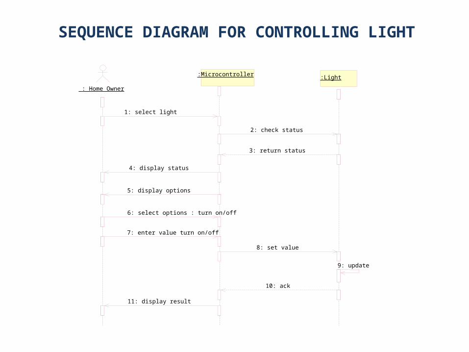
: Home Owner
:Microcontroller :Light
1: select light
2: check status
3: return status
4: display status
6: select options : turn on/off
7: enter value turn on/off
8: set value
9: update
10: ack
11: display result
5: display options
SEQUENCE DIAGRAM FOR CONTROLLING LIGHT
: Home Owner
:Microcontroller :Fan
1: Select Fan
2: Check status
3: Return Status
4: Display Status and menu
5: Select Turn on/off
6: Set Values
7: Update
8: ACK
9: Display result
SEQUENCE DIAGRAM FOR CONTROLLING FAN
: Home Owner
:Sensor :Microcontroller
: Fire Dept/Police Dept
4: Display warning
1.send signal
2: Return Signal
3: Notify Firedept
SEQUENCE DIAGRAM FOR FIRE ALARM/LPG LEAKAGE/INTRUDER
: Home Owner
:Microcontroller :Water level
1: select water level
2: check status
3: return status
4: display status
6: select options : turn on/off
7: enter value turn on/off
8: set value
9: update
10: ack
11: display result
5: display options
SEQUENCE DIAGRAM FOR WATER LEVEL DETECTION
ACTIVITY DIAGRAM
IMPLEMENTATION
MODULAR DESIGN
• Fire sensor moduleI(FFS 05)
The Fire sensor is used to detect fire flames . The module makes use of Fire sensor and comparator to detect fire up to a range of 2 meters. It uses a input voltage of +5VDC.
• Intruder detection module(PIR SENSOR)
The unit output is high whenever human’s motion is detected. In simple terms, it is a motion detector. This sensors measure infrared radiation emanating from objects in the field of view. Apparent motion is detected when an infrared emitting source with one temperature, such as human body, passes in front of source with another temperature, such as wall.
CONTD…
• Fan Module
It is directly connected to the microcontroller, it has only two functions ON/OFF. The user can switch on the fan or switch off the fan using the android app.
• Lights module
It is directly connected to the microcontroller, it has only two functions ON/OFF. The user can switch on the light or switch off the light using the android app.