Homework Assignment 10 Question 1 (1 Point Unless Otherwise Noted) 1. What is the 3-dB bandwidth of the circuit below? (a) ≈ 8 kHz (b) 31.83 kHz (c) 15.92 kHz (d) 100 kHz Answer: The capacitor sees an equivalent resistance = 2 = 10K (the current source has infinite internal resistance) and the time-constant is = = 10 s, so that the bandwidth is 1 (2) = 15.92 kHz ⁄ , and (c) is the answer. 2. What is the 3-dB bandwidth of the circuit below? (a) 63.6 Hz (b) 31.8 Hz (c) 5.07 Hz (d) 10.1 Hz Answer: The capacitor sees an equivalent resistance ||= 5K. The time-constant is = = 5 ms, so that the bandwidth is 1 (2) = 31.82 Hz ⁄ , and (b) is the answer. 3. What frequency is 2.2 decades higher than 500 Hz? (a) 1.01 kHz (b) 644 Hz (c) 522 Hz (d) 79.24 kHz Answer: 2.2 = log(500 ⁄ ), so that = 79.24 Hz, so (d) is the answer. 4. What is frequency is 3 decades down from 220 Hz? (a) 22 mHz (b) 220 mHz (c) 6.4 mHz (d) 190 Hz Answer: 3 = log(220 ⁄ ), so that = 220 mHz, so (b) is the answer. 5. A signal with amplitude = 4 V at 4 kHz decreases as frequency increases at −2 dB/octave. What is the amplitude in V at 13 kHz? (3 points) Answer: There are log 2 (13 2 ⁄ ) = 1.7octaves between 4 kHz and 13 kHz. Thus, the amplitude decreases by 1.7 × 2 = 3.4 dB. The new amplitude is 20 log 4 − 3.4 = 8.6 dB. This is equivalent to 2.7 V. 1
Transcript
Homework Assignment 10
Question 1 (1 Point Unless Otherwise Noted)
1. What is the 3-dB bandwidth of the circuit below?
Answer: The capacitor sees an equivalent resistance 𝑅 = 𝑅2 = 10K (the current source has infinite internal resistance) and the time-constant is 𝜏 = 𝑅𝐶 = 10 𝜇s, so that the bandwidth is 1 (2𝜋𝜏) = 15.92 kHz⁄ , and (c) is the answer.
2. What is the 3-dB bandwidth of the circuit below?
(a) 63.6 Hz (b) 31.8 Hz (c) 5.07 Hz (d) 10.1 Hz
Answer: The capacitor sees an equivalent resistance 𝑅𝑆||𝑅𝐿 = 5K. The time-constant is 𝜏 = 𝑅𝐶 =5 ms, so that the bandwidth is 1 (2𝜋𝜏) = 31.82 Hz⁄ , and (b) is the answer.
3. What frequency is 2.2 decades higher than 500 Hz?
(a) 1.01 kHz (b) 644 Hz (c) 522 Hz (d) 79.24 kHz
Answer: 2.2 = log(𝑓𝑥 500⁄ ), so that 𝑓𝑥 = 79.24 Hz, so (d) is the answer.
4. What is frequency is 3 decades down from 220 Hz?
(a) 22 mHz (b) 220 mHz (c) 6.4 mHz (d) 190 Hz Answer: 3 = log(220 𝑓𝑥⁄ ), so that 𝑓𝑥 = 220 mHz, so (b) is the answer.
5. A signal with amplitude 𝑣 = 4 V at 4 kHz decreases as frequency increases at −2 dB/octave. What is the amplitude in V at 13 kHz? (3 points) Answer: There are log2(13 2⁄ ) = 1.7octaves between 4 kHz and 13 kHz. Thus, the amplitude decreases by 1.7 × 2 = 3.4 dB. The new amplitude is 20 log 4 − 3.4 = 8.6 dB. This is equivalent to 2.7 V.
1
6. In the circuit below, what is the maximum current that can flow through 𝑅𝐿? Make reasonable assumptions.
Answer. Assume that for 𝑄2, 𝑉𝐵𝐸(𝑂𝑁) = 0.7 V. Thus, 𝑄2will turn on and starve 𝑄1 from additional base current when the current through 𝑅1 (which is also the current through 𝑅𝐿) is 𝐼 = 0.7 1.5⁄ =0.47 A.
7. What is the time constant of the circuit?
Answer: The resistance the capacitor sees is 𝑅𝑇𝐻 = 10K||10K = 5K, so the time constant is 𝜏 = 𝑅𝑇𝐻𝐶𝐿 = (5 × 10³)(1 × 10⁻⁶) = 5 ms.
8. Consider the voltage regulator below, implemented with a reference voltage 𝑉𝑅𝐸𝐹 = 1.25 V, an ideal op-amp and BJT with very large gain (𝛽 → ∞). Determine the output voltage to 4 significant figures. (5 points)
Answer: The op-amp and feedback loop maintains a voltage 𝑉𝑅𝐸𝐹 across 𝑅1 so the current through both resistors is 𝐼 = 𝑉𝑅𝐸𝐹 𝑅1⁄ . The output voltage is then
𝑉𝑂 = 𝐼(𝑅1 + 𝑅2) =𝑉𝑅𝐸𝐹𝑅1
(𝑅1 + 𝑅2) = 4.959 V
2
9. Name one important difference between an operational amplifier and a comparator. Answer: Comparators are very similar to op-amps, but comparators do not need and generally don’t have internal frequency compensation.
10. In the circuit below 𝑅1 = 10K,𝑅2 = 15K, and 𝑅3 compensates for the op-amp’s input bias current. What should it’s value be to be effective?
(a) 10K (b) 15K (c) 6K (d) 25K (e) Need 𝐼𝑂𝑆
Answer: Choose 𝑅3 = 𝑅1‖𝑅2 = 6K, so (c) is the answer.
11. True or false: the following is a low-pass active filter
Answer: False, it is a high-pass filter.
12. True or false: the following is a high-pass active filter:
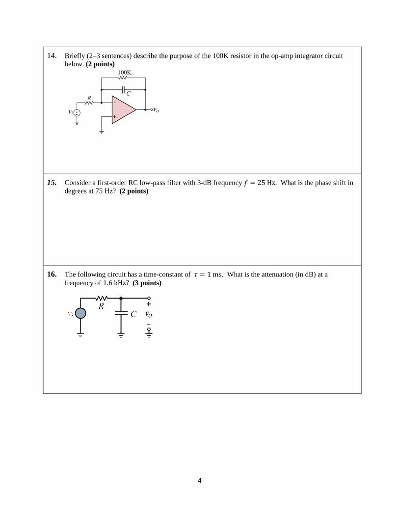
14. Briefly (2–3 sentences) describe the purpose of the 100K resistor in the op-amp integrator circuit below. (2 points)
Answer: Without the 100K resistor and with the input source disconnected, there is no dc path to supply the input bias current for the inverting terminal of the op-amp. Consequently, it will flow through the capacitor charging it up and eventually saturating the op-amp. The 100K resistor provides an alternate dc path.
15. Consider a first-order RC low-pass filter with 3-dB frequency 𝑓 = 25 Hz. What is the phase shift in degrees at 75 Hz? (2 points) Answer: The phase shift at 25 Hz is 45° and increases at 45° / decade. 75 Hz is log(75 25) = 0.48⁄ decades higher than 25 Hz. Thus, the phase shift is 45 + 0.48 × 45 = 67°. A more accurate calculation gives the phase shift as tan−1(75 25⁄ ) = 72° .
16. The following circuit has a time-constant of 𝜏 = 1 ms. What is the attenuation (in dB) at a frequency of 1.6 kHz? (3 points)
Answer. This is a 1st order low-pass network with a corner frequency of 𝑓3dB = 1 (2𝜋𝜏) = 159.2 Hz⁄ . The attenuation is 20 dB/decade above 𝑓3dB and 1.6 kHz is 1 decade higher than 159.2 kHz. Thus, the network will attenuate at 20 dB at 1.6 kHz. An alternate calculation is 20 log ��1 + (1.6 0.159⁄ )2� = 20.1 dB.
4
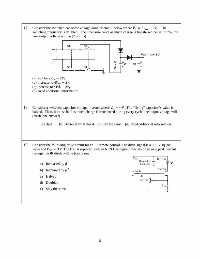
17. Consider the switched-capacitor voltage-doubler circuit below where 𝑉𝑂 = 2𝑉𝐼𝑁 − 2𝑉𝐹. The switching frequency is doubled. Then, because twice as much charge is transferred per unit time, the new output voltage will be (2 points)
(a) Still be 2𝑉𝐼𝑁 − 2𝑉𝐹 (b) Increase to 4𝑉𝐼𝑁 − 2𝑉𝐹 (c) Increase to 4𝑉𝐼𝑁2 − 2𝑉𝐹 (d) Need additional information
Answer: (a)
18. Consider a switched-capacitor voltage-inverter where VO = −VI. The “flying” capacitor’s value is halved. Then, because half as much charge is transferred during every cycle, the output voltage will (circle one answer)
(a) Half (b) Decrease by factor 4 (c) Stay the same (d) Need additional information Answer: (c)
19. Consider the following drive circuit for an IR remote control. The drive signal is a 0–5 V square wave and 𝑉𝐶𝐶 = 9 V. The BJT is replaced with an NPN Darlington transistor. The new peak current through the IR diode will be (circle one):
a) Increased by 𝛽
b) Increased by 𝛽2
c) Halved
d) Doubled
e) Stay the same
Answer: 𝑉𝐵𝐸(𝑂𝑁) for a Si Darlington is about double that of a normal BJT. Thus, about double the current must flow before the Darlington turns on.
5
20. Classify the following filter according to topology (KRC, equal component Sallen-Key), frequency behavior (LP, BP,…), and order.
Answer: KRC (or Sallen-Key) HP filter, 2nd order.
21. Classify the following filter according to topology (KRC, equal component Sallen-Key), frequency behavior (LP, BP,…), and order.
Answer: Multiple-feedback LP filter, 2nd order.
22. Classify the following filter according to topology (KRC, equal component Sallen-Key), frequency behavior (LP, BP,…), and order.
26. A filter has the following transfer function below (the values were chosen for ease of calculation, and are unrealistic for actual implementation). At what frequency (in Hz) will it “ring” in response to a step function? (4 points)
𝐻(𝑠) =
𝑠𝑠2 + 16𝑠 + 100
Answer By inspection 𝜔0 = √100 = 10 rad s⁄ , and 2𝜁𝜔0 = 16, so that 𝜁 = 0.8. The circuit will “ring” at 𝜔0√1− 0.82 = 6 rad s⁄ = 0.956 Hz.
27. A filter has the following transfer function below (the values were chosen for ease of calculation, and are unrealistic for actual implementation). Will the filter exhibit overshoot in response to a step input? Support you claim. (3 points)
𝐻(𝑠) =1,000
𝑠2 + 16𝑠 + 1,000
Answer By inspection 𝜔0 = √1000 = 31.6 rad s⁄ , and 2𝜁𝜔0 = 16, so that 𝜁 = 0.25. The damping ratio is small are there will be significant overshoot. In fact, the % overshoot will be
𝑃𝑂 = 100𝑒� −𝜁𝜋�1−𝜁2
�≈ 44 %
Question 2 (Filters) A filter has the transfer function below. Determine the output 𝑦(𝑡) if the input is 𝑥(𝑡) = 3 cos(100𝜋𝑡 + 45°). (6 points)
𝐻(𝑠) =1,000
𝑠2 + 16𝑠 + 1,000
Solution In phasor form the input is 𝑥 = 3∠45° and the transfer function at 𝑠 = 𝑗𝜔 = 100𝜋 is
𝐻(𝑠 = 𝑗𝜔) =1,000
−(100𝜋)2 + 𝑗1,600𝜋 + 1,000= 0.0102∡ − 177.05°
The output in phasor form is (3)(0.0102)∡ − 177.05° + 45° = 0.0307∡− 132.05°, so the output is
𝑦(𝑡) = 0.0307 cos(100𝜋𝑡 − 132.05°) V
8
Question 3 (Principles) The voltage source in the network below (a) is shown in (b). What is the time constant of the circuit? Sketch 𝑖𝐿(𝑡) for 𝑡 ≥ 0. Calculate 𝑖𝐿(𝑡) at 𝑡 = 4 ms to 4 significant digits, and show this on the plot. (8 points)
(a) (b)
Solution
The time constant is 𝑅 𝐿⁄ where 𝑅 = 𝑅1||𝑅2 = 4 Ω. Thus, 𝜏 = 2 ms. For 𝑡 ≤ 4 ms
𝑖𝐿(𝑡) =166 �1 − 𝑒−𝑡 𝜏⁄ � =
166 �1 − 𝑒−𝑡 2 ms⁄ �
so that at 𝑡 = 4 ms, 𝑖𝐿 = 2.306 A. For 𝑡 > 4 ms, the current decays exponentially and the time constant is 2 ms.
9
Question 4 (Filters) A filter has the transfer function below. At what frequency (in Hz) will it “ring” in response to a step function? (4 points)
𝐻(𝑠) =𝑠 + 20
𝑠2 + 8𝑠 + 100
Solution
By inspection 𝜔0 = √100 = 10 rad s⁄ , and 2𝜁𝜔0 = 8, so that 𝜁 = 0.4. The circuit will “ring” at 𝜔0√1− 0.42 = 9. 17 rad s⁄ = 1.4587 Hz.
Matlab script for plotting step response.
% s + 20 % ---------------- % s^2 + 8s + 100 % num = [1 20]; % Coefs of s terms with s-terms in descending order den = [1 8 100]; % Coefs of s terms with s-terms in descending order sys = tf(num,den); [y, t ] = step(sys,2); plot(t,y,'linewidth',2); grid on; xlabel('Time (s)','fontsize',16);
ylabel('Repsonse','fontsize',16);
Note that 1 686 = 1.458 ⁄ which is close to the calculated frequency.
10
Question 5 (Sensitivity) For the filter shown, determine the 3-dB frequency in Hz. Then determine the sensitivity relative to the value of the inductance. That is, determine 𝑆𝐿
𝜔0 where 𝜔0 is the 3-dB frequency in rad/s. (5 points)
Solution
The 3-dB frequency is 𝜔0 = 𝑅 𝐿⁄ = 1 × 10⁶, so that 𝑓0 = 159.2 kHz. Further
𝑆𝐿𝜔0 =
𝐿𝜔0
𝜕𝜔0
𝜕𝐿=
𝐿𝜔0
𝜕 𝑅𝐿𝜕𝐿
=𝑅𝐿𝜔0
𝜕𝐿−1
𝜕𝐿= −
𝑅𝐿𝜔0
1𝐿2
= −𝑅𝜔0𝐿
= −1
Question 6 (Filters) A second order filter has poles at 𝑠 = −1 2⁄ ± 𝑗 √3 2⁄ . The transmission is zero at 𝑗𝜔 = ±2 rad/s and is unity at dc (𝜔 = 0). Determine the transfer function. (10 points) Solution
Question 7 (Filters) Consider the active filter below. (a) What type of filter is this (LP, BP, Notch, etc.)? To get credit, you must motivate your answer with a short explanation. (3 points) (b) What is the order of the filter? To get credit, you must motivate your answer with a short explanation. (3 points)
Solution
(a) There are three BP filters cascaded and the overall response is BP. The individual sections are BP because at low frequencies the 10-nF capacitor connected to the inverting input is effectively an open circuit so the inverting input is not connected to the signal and the noninverting input is grounded. At very high frequencies the same 10-nF capacitor is a short which shorts the input signal at the inverting input to ground. At some the resonance frequency the reactance’s of the 10-nF capacitors are comparable to the resistors and the op-amp can amplify the signal.
(b) Each filter section is a 2nd order (there are two reactances) and there are three such sections. Thus, this is a 6th order filter.
Question 8 (Filters) An engineer measures the 3-dB frequencies of a symmetric bandpass filter as 9.34 kHz and 10.21 kHz. What is the resonant frequency (𝑓0) and 𝑄 of the filter? (4 points)
Solution
For a symmetric narrowband bandpass filter
𝑓0 = �𝑓𝐿𝑓𝐻 = √9.34 × 10.21 = 9.77 kHz
The bandwidth of the filter is 10.21− 9.34 = 0.87 kHz and 𝑄 = 𝑓𝑜 𝐵𝑊 = 9.77 0.87 = 11.2.⁄⁄
12
Question 9 (Filters) A filter has the transfer function below. Use either Matlab or SPICE to plot the step response of the filter over a range 0 to 10 s. Upload your file to ICON. (15 points) Hints: For SPICE, note that Micro-Cap SPICE has Laplace voltage sources. For Matlab, there are the “sys” and “step” functions.
𝐻(𝑠) =1
𝑠2 + 8𝑠 + 100𝑠
𝑠 + 1
SPICE Solution
In Micro-Cap SPICE, build the following circuit using the “LFVofF” Laplace component. Set the source 𝑉𝑠 to generate a square wave with an amplitude of 1 V and a long period, say 100 s. This will simulate a unit step at the input.
Click on the LFVofF component and enter the following text: 1/(s^2+8*s+100)*(s/(s+1)). Next, perform a transient analysis, yielding the graph below.