Technical Books Christchurch 20 WINDMILL CENTRE RICCARTON PHONE/FAX 348-0220 MOTOR MANUAL REFERENCE ONLY THIS BOOK MAY NOT BE BORROWED l C 1938903 2. 11t>1\ cJ-a-. C 7zfc 77 C'3 7?-/ cs77 Ct372jcf377 : i+ o (ld 0- Mo+or Co - \\ / ... _01 C1 93S90 32 HONDA MOTOR CO., LT D.
Transcript
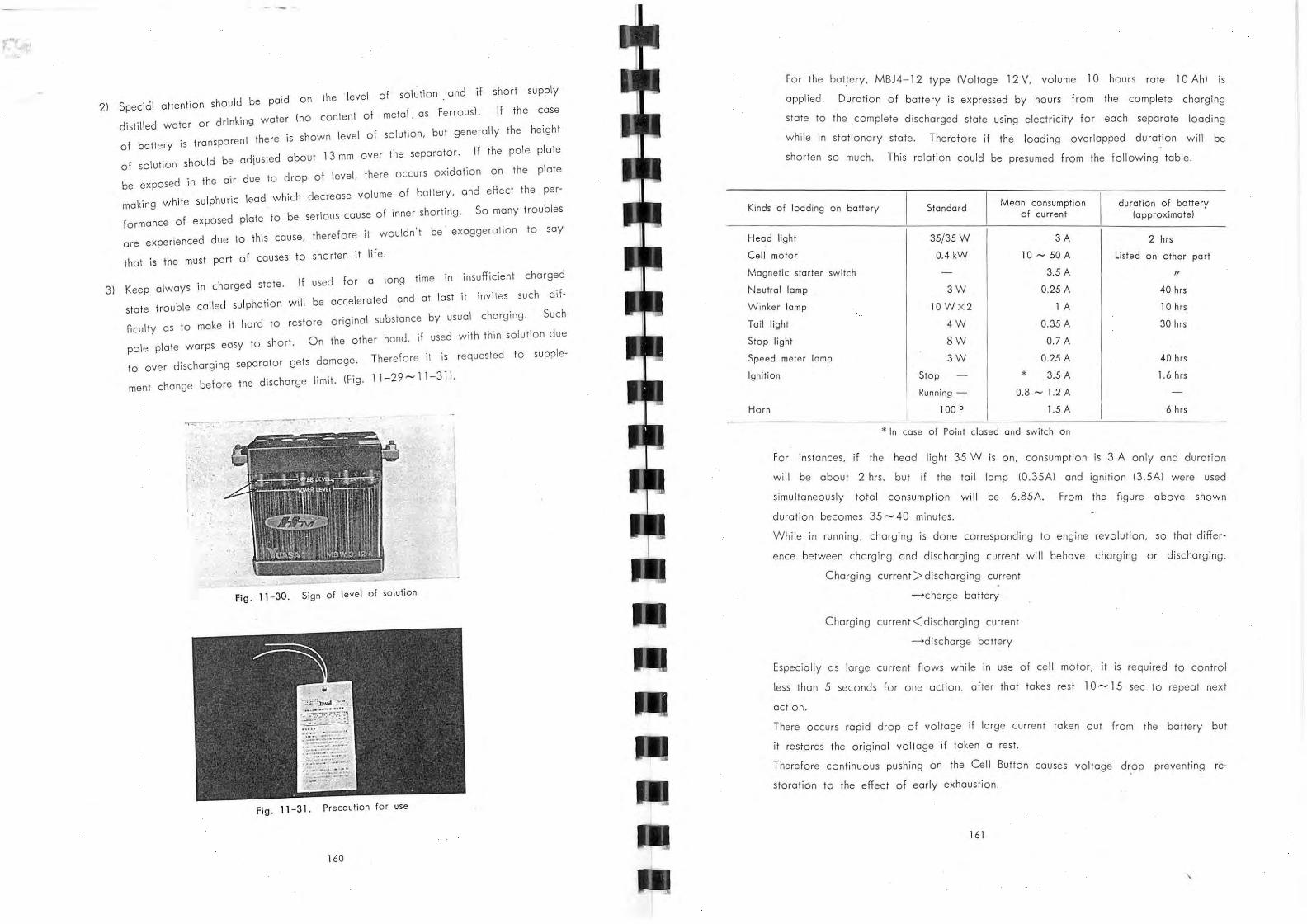
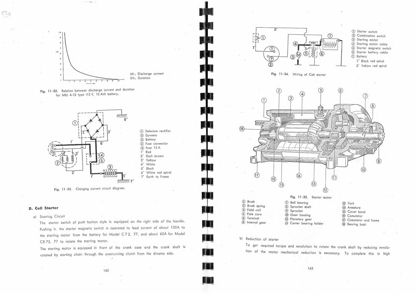
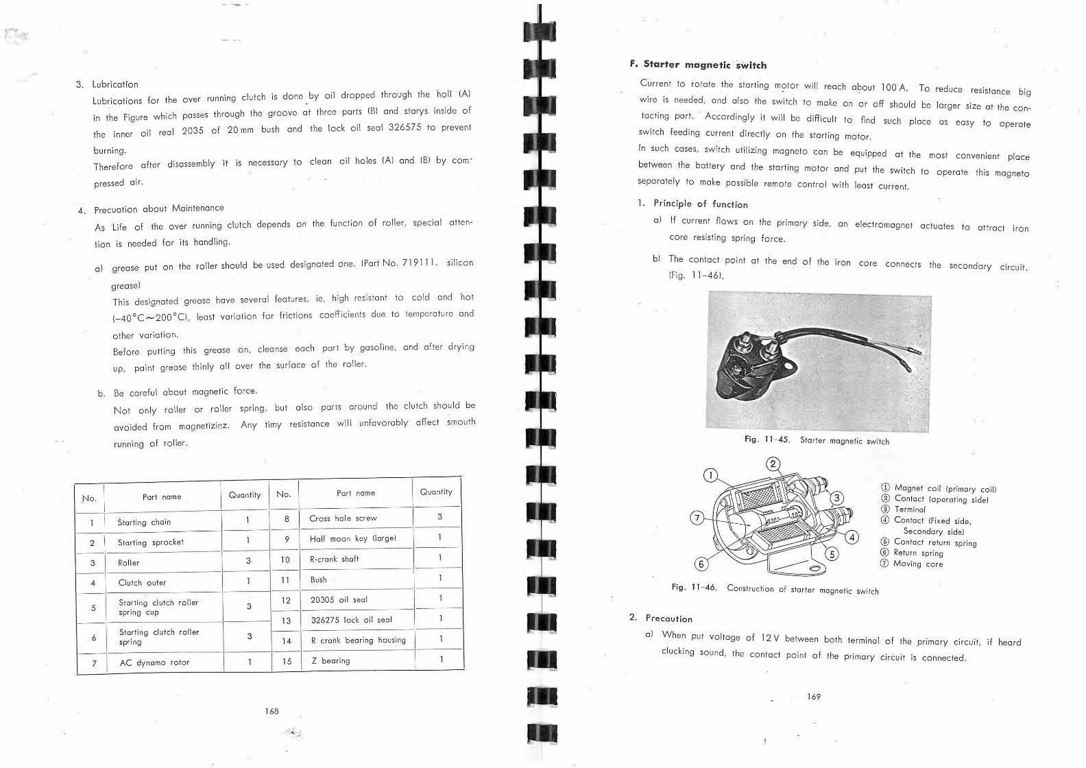
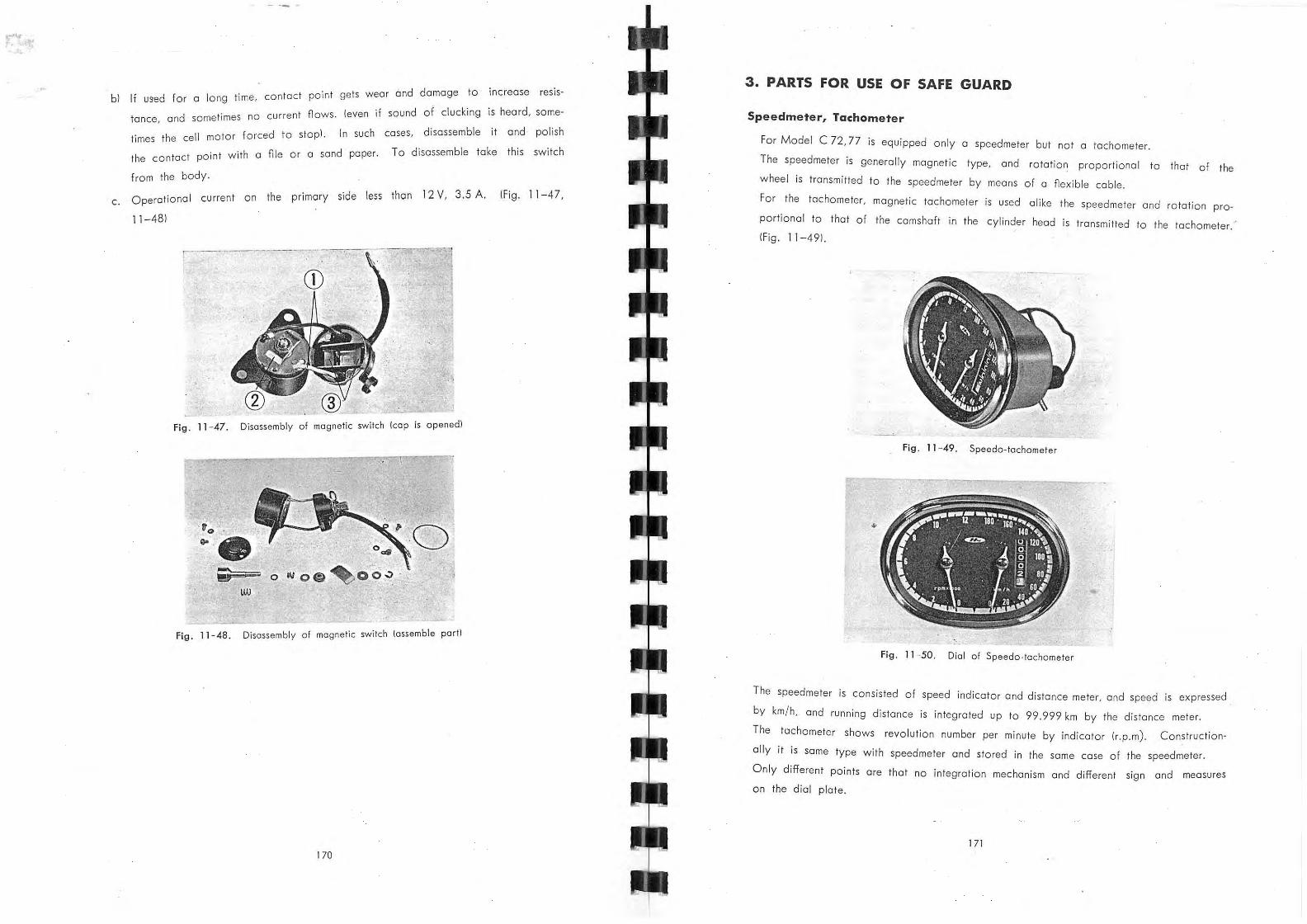
Technical Books Christchurch
20 WINDMILL CENTRE RICCARTON
PHONE/FAX 348-0220
MOTOR MANUAL
REFERENCE ONLY THIS BOOK MAY NOT
BE BORROWED
l
C19389032.
11t>1\cJ-a-. ~~ C 7zfc 77 C'37?-/cs77 Ct372jcf377
: i+o (ld 0- Mo+or Co - \\ / ~co ... ~ _01
C1 93S90 32
HONDA MOTOR CO., LTD.
HONDA 250 MODEL C72
HONDA 250 MODEL CS72
HONDA 250 MODEL CB72
Ge."?..9.2.~775
HON 18 JU L 1996
PREFACE
This Shop Manual contains general data and information, and procedures relative
to vehicle maintenance, over-haul and repairs for the models covered by Honda 250
and Honda 300 equivalent to Model C72· C77, CB72· CB77, CS72' CS77. (3 c:>Sc.c) Therefore, information in this manual will be suitable instruction for servicemen
and mechanics of Honda to assist them to efnciently se rvice and repair these machines.
Now, in this case, mechanica l arrangement means to repair a veh icle when it is
out of order and restore it to the ordinary state as well as to prevent it from any
tr ouble by periodically inspecting the vehicle.
The contains of th is book are divided into nve chapters, including main standards,
disassembly-assembly, const ru ction, wiring diagram and trouble shooting.
Each chap ters are separated into sections. Disassembly.assembly Ilhe 2nd chapte rl
is divided into 2 sections - Engine and Frame. The section of Engine is described both
model C72· 77, CB72· 77, but that of Frame is done only mode l CB72· 77.
In regard to the Frame of mode l C72· 77, please refer to the previously
published Shop Manual fo r Hondo 125· 150.
An effort has been made to produce a manual avoiding fundamental principle
and theory by expla ining th e actual mechanism.
Special emphasis has been placed an illustrations and charts to make it easy for
the service man to understand without reading every line. We hope this will be of
some use to you.
This manual will be revised without notice.
January, 1960.
HONDA MOTOR CO., LTD.
TECHNICAL SECTION
EXPORT DEPARTMENT
No. 5- 5, Yaesu-cho, Chuo.ku,
Tokyo, Japan
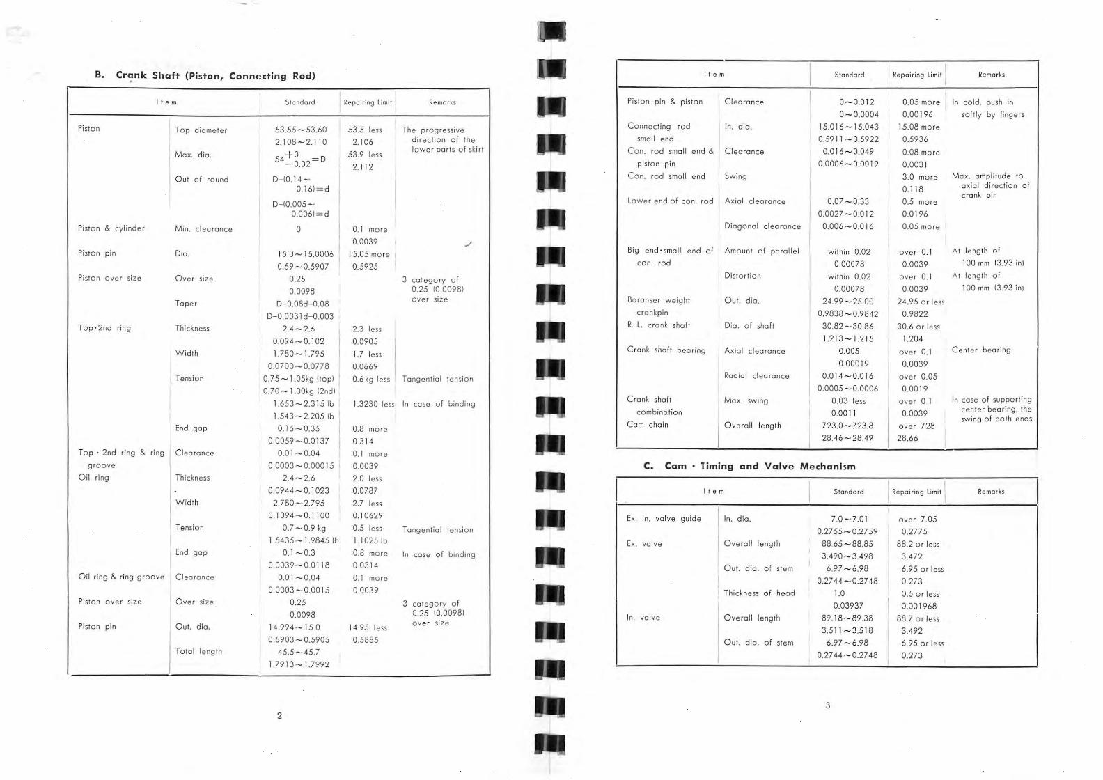
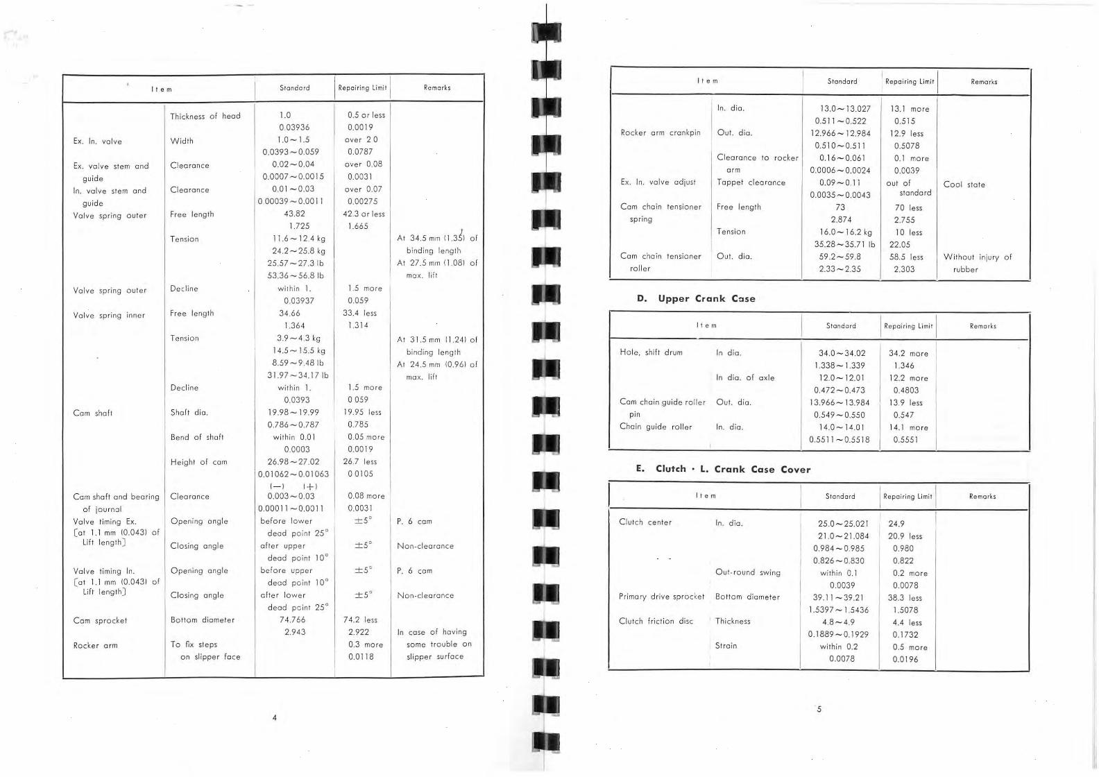
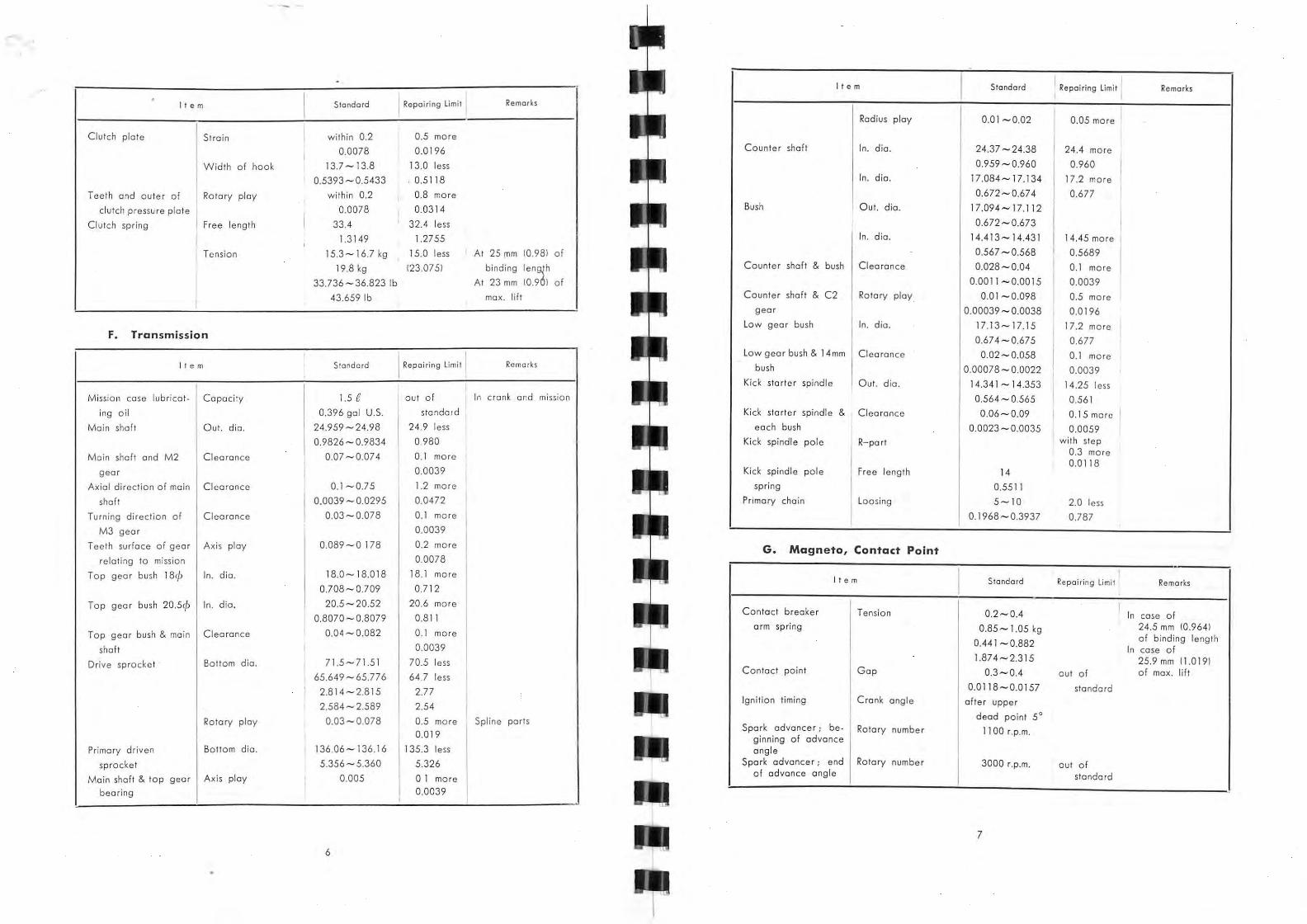
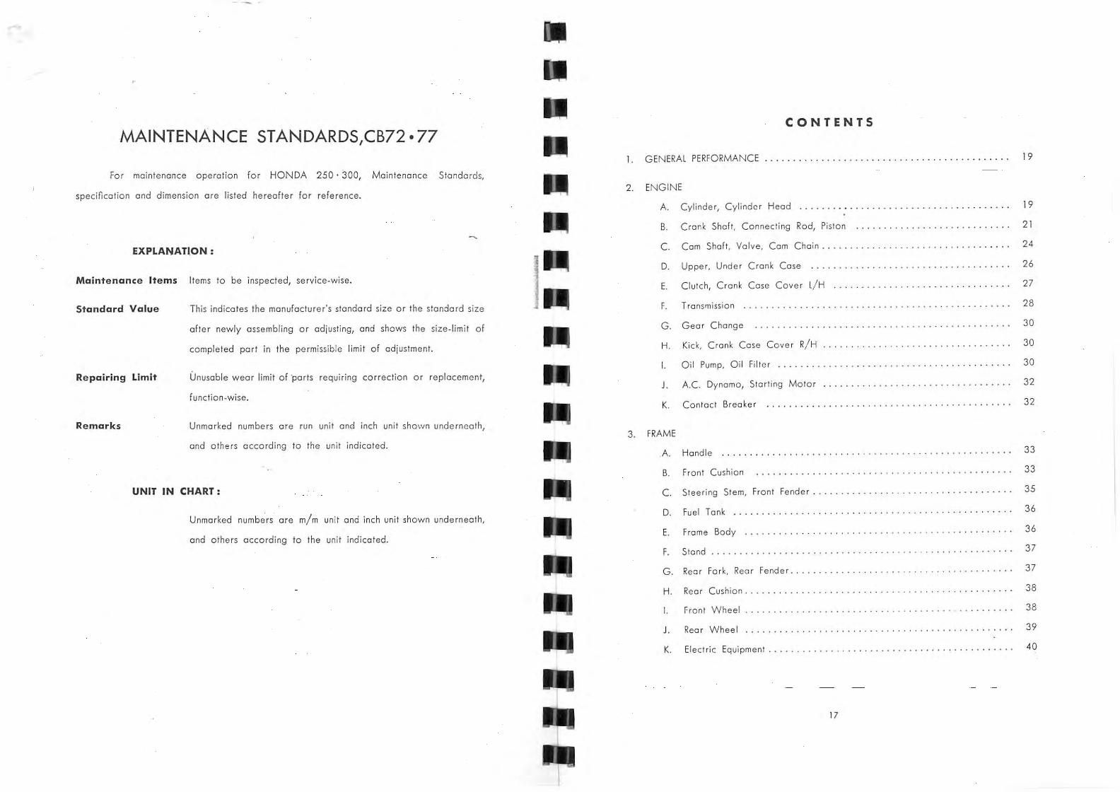
MAINTENANCE STANDARDS, C72· 77
For maintenance operation for HONDA 250 . 300, Maintenance Standards,
specification and dimension are listed hereafter for reference .
EXPLANATION:
Maintenance Ite ms Items to be inspected, se rvice-wise.
Standard Value
Repairing Limit
Remark s
I.. This indicates the manufacturer's standard size or the stondard size
after newly assembling or adjusting, and shows th e size-limit of
complet ed part in the permissible l imit of ad justment.
Unusable wear limit of parts requiring correction or repla cemen t,
function.wise.
Unmarked numbers are ru n unit and inch unit shown underneath,
and others according to th e unit indicated.
UNIT IN CHART:
Unmarked numbers are m/m unit and inch unit shown underneath,
wide ring Piston ring & groove Clearance 0.045 - 007 0.15 more Exc hange
Inlet valve ISteml Out. dia. 6.98-6.99 6.96 less Exchange
0.274 - 0.275 0.274 I or rectify
Inl et valve ISeatl Angle 90 0 -9 1 0 out-standa rd I Excha nge
ITopl 0.0059
* 0.04-0.07 i< 0.15 more Exchange
* 0.0059 Piston ri ng & groove Clearance 0.01-0.0 4 0.1 more Exchange
(Second I 0.00393 Piston ring & groove Clearance 0.0 1-004 0.1 more Exchange
10ili 0.00393 Piston ri ng oversize O versize 0.25 3 category of
0.00984 0.25 ove rsize
Inlet valve Overall 89.96-89.98 89.6 less Exchange
lenglh 3.541 -3.542 I 3.521 Valve spring flnn er! Free length 37.5 4 I 36.0 less Ex change
1.477 1.417 Diagonal 0.8 less 1.5 more Exchange
degree
Tension 7.6 - 8.4 kg 60 kg less Exchan ge
18.9 -20' kg 16.0 kg less I 16.754-18.518 I 13.227 i 41.667 - 44.31 3 I
35.273
C. Cam Shaft Valve Cam Chain Valve spri ng tOuler! Free length 43.36 42.0 less Exchange
1.707 I 1.653
1 t e m I Standard I Repei,i '9 limit Adiu5fing poi :"! 1 I Remarks Diagonal 0.8 less
,
1.5 more Exchange
degree 1
Com shaft
I Out. dia. 19.996 - 20.009 19.95 less
I Exchange
lBearing partl 0.787 -0.787 0.785 Cam (Bearing parl l Height In 31.67-31.71 31.4 Exchonge
1.246 - 1.248
I 1.236
I Ex.30.54 - 30.58 30.2 less I 1.202 - 1.203 1.188 ,
Max. lift Com shaft lift In 5.69 , , I ,
0.118 , Ex. 4.56
0.179
Tension 16.9- 18. 1 kg 15.0 kg less Exchange
34.4 - 34.6 kg 32.0 kg less I 37.257 -29.903Ib, 33.0691bs le"l 7 5.838-7 6.279Ib, 70.547 Ibs less '
Exhaust valve guide In . dia. 7.0 -7.0 1 7.05 more Exchange
0.275 - 0.2759 0.2775 Inlet valve guide In. dia. 7.0-701 7.05 more Ex chang e
0.275 - 0.2759 0.2775 Touch width 1.0 20 more
I Rectify Repair of cylinder Valve seat
! 0.039 0.08 head
Cam sprocke,t Nos. of 32 Rocker o,m In. dia. 13.0 -1 3.027 13.1 more Exchange
complete teeth , I I
1 Bottom dia, 74.766 74.2 less Exchange
2.943 2.921
0.51 1-0.512 0.515
I Rocker arm shaft Out. die. 12.966 -1 2.984 12.9 less Ex change I tRacke r orm partl 0.510 - 0.51 1 0.507
24 25
' I t e m I Standard I Repaidng limit I Adjusting point Remarks It e m
I Standard I Repai ring limit Adjusting point Remarks I
Rocker arm shaft Out. dio. 16.994-16.976 16.95 less Exchange L/ H cover attaching I Flatn ess within 0.03 0.06 more Rectify
IInloy port of heodl 0.669 - 0.668 0.667
Rocker arm shaft In. dio . 2.5
10il partl 0.0984
T oppe l clea rance In. Ex. 0.08-0.12 out-standard Rectify Cold type
0.003 - 0.047
Cam chain Out. dia. 40 38 less Excha nge Aging and crock
face of upper cronk 0.001 0.002 case I Com chain guide Out. dia. 59.5 58.0 less Exchange Aging and crack roller I
! 2.342 2.28 of rubber should
I I not remain
In. dia. 14 .0-14.018 14.1 more Exchange i ,
tensioner roller 1.574 1.496 ! of rubber should
nof be.
Com chain tensioner Free length 63.3 60.0 less Exchange
roller (Spring) 2.492 2.362
Tension 7 kg 5.5 kg less Exchange Referential value-
I 0.55 1- 0.5518 0.555
I Com chain guide I Out. dia. 13.966 - 13.984 13.9 less Exchange roller pin 0.549 - 0.550 0.547
I Oil level gauge Dia. 2.9-3.1 2.8 less Exchange "0" ring 22mm 0.114- 1.22 0.110
15.432 1bs 12.1251bs control by ove r T ightness 2.0 0.5 less Exchange
all length Valve timing ex. Opening before lower out-standa rd Rectify Check at 1.1 m/ m
angle dead point 35 ° ±5° Un case of liftl
Closing after uppe r out-standa rd Rectify Check at 1.1 m/ m angle dead point 10° ±5° (In case of lift)
Valve timing In . Opening before upper ou t-standard Recti fy Check at 1.1 m/ m angle dead paint 5 ° +5° lin case of liftl
Closing after lower out-standa rd Rect ify Check at 1.1 m/ m angle dead point 30° +5° Un case of lift)
0.078 I
0.0019 Und er cronk case Flatness within 0.03 0.06 more Rectify
attaching face of 0.001 0.002 caver L/ H
Under crank case Flatness within 0.03 0.06 more Rectify (Seam su rface of 0.0012 0.0023 I upper · under!
Under cronk case i Slip oul of within 0.05 0.1 more Rectify seam surface I L/H or R/ H 0.00019 I 0.0039
,
D. Upper' Under Crank Case E. Clutch. Crank Case Caver L/ H
I t e m I Standa rd I Repairing limit I AdjuSiing point I Remarks
Upper · under cronk In. dia. 65.97 -65.987 66.04 more Exchange Combined with
case lPart of center 2.597 - 2.598 2.60 upper and unde r
bearing) and then measure
Upper' under crank In. dio. l/H76.97 -76.987 76.93 more Exchange Combined with
case IPart of bear- R/ H64.97 -64.987 64.93 mo re upper and under
ing l/H, R/ HI 3.0307 - 3.0309 3.0287 and th en measure , 2.557 - 2.558 2.556
I Upper' under~lcronk In. dia. 61.985-61.996 62.04 more Exchange Combined with
case lPart of mis- 2.440 - 2.4407 2.442 upper and under sian shaftl and then measure
It e m I Standard : Repairing limit I Adjusting point I Remarks
Clufch friction disc
I Thickness 2.9-3.0 2.5 less Excha nge One set is 6
0.114-1.18 1 0.984 sheets In . dia. 112
4.409 Flatness within 0.2 0.4 more Exchange
0.0078 0.015 Clutch plate Thickness 2.0 1.6 less Exchange Use 5 sheets
I 0.078 0.0629 flotness within 0.2 0.4 more Exchange or
I 0.0078 0.015 Repa iring
Upper ' under crank In. dia. 25.0 - 25.021 25.1 more Exchange Combined with I case (Part of kick 0.984 - 0.985 0.988 upper and unde r spindle) Rec tify and then measure
Upper' under cronk Flatness within 0.03 0.06 more
case (Seam surface l 0.001 0.002 Rect ify
I Out. dio. 135
5.314 Clutch center and C learance wirhin 0.3 0.3 more Excha nge Clearance at out.
clutch plote of rotary 0.0118 0.0118 dia. of plate direction
Cylinder attaching Flatness within 0.03 0.06 more
face of upper cronk 0.001 0.002 Rectify
case
Clutch cente r and Clearance
I with in 0.1 0.3 more Exchange
mission shaft of ro tary 0.0039 0.0118 direction
I
27 26
-'
, t e m Standard I Repa;r;'g L;m;' Adjusting point Remar,ks
I t e m Standa rd I Repa;r;,g Lim;' Ad ju sting point Remarks
Main shaft and M 3 Clearance 0.03 - 0.078 0.1 more Exchange C1ulch oute r compo Teeth 47 11.851 gear of ro tary 0.0012 - 0.00307 0.0039
(with sprocket) direction
Bottom die . 136. 15 - 136.16 135.5 less Excha nge Measure bottom ( Mission gear Bock rush 0.089 - 0. 178 0.2 more Excha nge 5.360 - 5.3606 5.334 die. rolle r dio. 0.0035 - 0.0070 0.0078
0.35 Top gea r In. dia. 18.0 -18.018 18.2 more Exchange In . die. 88.0 - 88 .035 Refe rential value 0.708 - 0.709 0.7 16
3.464 - 3.465 Top gear In. dia. 8.0 - 8.0 15 8.06 mo re Exchange Clutch center and
I
Axial 0.027 - 0.067 0.2 more Exchange
mission shaft clearance 0.001 - 0.0026 0.0078 more (lifter rod partl 0.3 14- 0.3 15 0.3 17
Top gea r {Bushl In. dia. 20.5 - 20.521 20.6 mo re Exchange
0.807 - 0.8079 0.811 Cl utch pressure pla te Flatness within 0.1 0.3 more Exchange Top gear bush and Clearance 0.08 1 0 .1 more Exchange lParl of 20.5911
0.0039 0.0118 mission shaft 0.00318 0.0039 In. die. '112 14.4091
C1ulch spring I Free length 33.4 32.4 less Exchange
1.314 1.275
Dri ve sprocket BO llom dia. 65.649 - 65.776 64.7 less Exchange
Diagonal 1.0 less 2.0 more Exchang e {Rotary direction l 0.001 18 - 0.00307 0.0984 I degree 0.0393 0.0787 , Counter shaft In. dia. 24.37 - 24.385 24.4 more Exchange I Load 15.3 -1 5.7 kg 13.6 kg less Exchange (gea r sidel 0.959 - 0.960 0.9606
33.73 - 34.6 1I bs 29 .982 1bs Coun te r shaft O ut. dia. 24 .96 - 24.939 24. 9 less Exchange Cronk case cove r Flatness wi thin 0.0 1 0.06 mo re Rec tify 0.982 - 0.981 0.980
L/ H 0.0003 0.0023 Bush 14 mm In. d ia . 14.375 -14.393 15.2 more Exchange Cronk case cove r L/ H In. die. 58.0-58.046 0.565 - 0.566 0.598
IParl of oil fllted 2.283 - 2.285 Out. dia. 24.98 - 25.013 Exchange Cronk cese cover Tightness 0.5 mo re out· standard Exchange 0.983 - 0.984
L/H I" 0" ringl 0.0197 C ounter shaft and Cleara nce 0.01-0.098 0.2 more Exchange Cronk case cave r In. die . 14.0 - 14.018 14.1 more Exchang e C~ gear of ro ta ry 0.00039 - 0.0038 0.0078
L/H lParl of sh ifl 0.551-0.5518 0.555 di rect ion spindle) Low gear C rossover 2 1.667 - 2l.71 4 21.61ess Exchange
Crank case cove r Thickness 0.3 - 0.4 When disassembly thickness 0.853 - 0.85 4 0.850 L/H IPackingl and maintenance, Kick storto r spindle Clea ra nce 0.022 - 0.052 0.15 mo re Exchange
0.01 18-0.0157 exchange should and bush 14 mm 0.0087 - O. 0020 4 0.0059 be done each time· Bush C 14 mm O ut. d ia. 17.094-17.112 17.05 less Exchange
0.672-0.673 0.67 1
F. Transmission In. dia. 14.413-14.4 31 14.53 ma re Exchange
0.567 - 0.568 0.572
" e m I Standard I Repa;r;,g L;m;' I Ad juSI ;,g po;" Re marks Mission gear Fi rs t 3. 12
gea r rotio
T ro nsmission Type Four speed 2nd 1.74
Constant mesh gear
Main sha fl Out. d ia. 24.959 - 24 .98 24.9 less Exchange 3rd l.27
0.968 - 0.983 0.980 Top l.00 Main shaft and M, C learance 0.02 - 0.074 0.1 more Excha nge
gear 0.007 - 0.0029 1 0.0039 Main shaft Axial 0.1- 0.75 1.2 more Exchange
Kick spindle pole Free lengl h 14 13.5 less Exchange spri ng 0.551 0.531
Clearance 0.0039 - 0.0295 0.0472
29 28
•
I t e m I
Standard Repai"'9 Umit I AdjusH'9 poi,t I Remorks 1 t e m I Standa rd I Repc""9 UmH I Adjusti'9 poi", I Rema rks
Oil pump gea r Back rush 0. 106-0.21 0.4 more Exchange
0.004 17 -0.0082 0.0 15 Kick spindle pole Out. dio. 5 4.5 less Exchange
Oil pump gea r side Clearance 0.04-0.089 0.1 more Exchange
face and side cover 0.0015 - 0.0035 0.0039
bush pin 0.196 0. 177
Overall 13 12.5 less Exchange
Oil pump gea r and Clearance 0.0 13- 0.05 0.3 more Exchange
pin 0.005 11- 0.000 19
1
0.00 118
Oil nlle r shaft a,d Clea rance 0.0 12- 0.048 0. 1 mo re Exchange
oil filte r rotor 0.00472-0.00188 0.0039
length 0.511 0.492
Primary chain Deflection 5 - 10 20 mo re Exchange Show by max.
I
0.196 - 0.393 0.7874 swing of loosing
Roller 5 X 6.25 No. Reqd. 12 pieces
Oil filter rotor Out. dio. 57
2.244
Oil nller cha in Loosing 5-10 15 more I Exchange Measure the omp-
0. 196-3.937 5.905 litude at the center
.
G. Gear Change
I t e m I
Standard I Repoiri'9 UmH i Adjustin9 poi", I Remarks
Gear shift fork In. dio. 34.0 - 34.025 34.2 more Exchange
1.338-1.339 1.346 J. A. C Dynamo Starting Motor
Gear shift drum Out. dio. 33.95 - 33.975 33.9 less Exchange
1.336 -1 .337 1.334 Drum and shift fork Clearan ce 0.025-0075 0.25 more Exchange
l ie m I Standard I Repoi';'9 limit i Adjusti'9 poi", I Remarks
0.0098 - 0.0295 0.0098 Spark pe rformance 3 Needle B mo re 300 r.p.m. 7 less Exchange 3 Needle gap
Gear change pedal In. dio. 17.0 - 17.027 17.3 mo re Exchang e on ignition gap 0.3 14 0.275
0.669 - 0.670 0.709 Charg ing perfo rmance Charging 2.0-3.0A out-standard Exchange start of charging,
on dynamo current at 1700 r.p.m.,
afte r thot, at
500 r.p.m. H. Kick, Cronk Case Cover R/ H
Dynamo starter and Clearance 0.5 0.8 more Exchange
rotor 0.0 197 0.0314
Starl ing clutch oute r Ou t. dio. 0-0.06 0. 1 more
and dynamo gap 0-0.00236 0.0039
r I e m
I Standard I Repoi ,i'9 limit I AdjuSli'9 poi,! I Remarks
I I Exchange Kick starto r gear Shaft Out. 14.34 1 - 14.353 14.25 less
Cross screw 6 X 24 Tight ing 0.5 m- kg oUI-standard Rectify When lighting, torque 3.615 ft l lb screw rod should ,
be needed. I Clutch roller spring Free length 25 - 31 24 less
1
Exchange I , 0.984 - 1.220 0.944
Cl utch rolle r spri ng In. dio. 4.1 - 4.25 4.3 more Exchange
dia . 0.564 - 0.565 0.561 Kick startor gear Clearance 0.016 - 0.104 0.3 more Exchange
and coWr R/ H 0.00063-0.0409 0.01 18 , Cover Rt J\l. Flatness within 0.05 0.1 more Rectify or
~;... 0.000196 0.0039 I exchange .'.
I. Oil Pump, Oil Filter ICap l 0. 161 - 0.167 0. 169 Oul. dio. 5.2 - 5.3 5.0 less Exchange
0.2047 - 0.2086 0.196 I
Storting sprocket of Out. dio. 37.175 - 37.2 37. 1 less Exchange I It em
I Standard I Repoiri'9 limit : Adjusti'9 poi", Remarks
clutch outer jou rnal 1.463 -1 .464 1.460 I Starting motor Voltage 12 V I
, I Oil pump drive gear Teeth width 4 0. 157
I I
I Horse power 0.4 KW out-standard Exchange
Bend 0.05 I 0.1 mo re Exchange I , 0.00019 0.00393
Roting 30 sec out-standard Exchange I Oil pump drive gear Bock rush 0.085 - 0. 127 0.15 more Rectify Adiust by packing
and M. cronk gea r 0.00334-0.050 0.059 I Oil pump gear top Clearance 0.025 - 0.05 0.1 more
I Exchange
and inside wall 0.0098 - 0.0019 0.00393 I
31 30
K. Contact breaker J I e m Standard Repairing Limit Adjusting point Remarks
I I e m Standa rd Repairing l imit Adjusting point Remarks Co rbu retto r Valve seat 2.591
* 2.091
Contac t pOint Max. gap 0.35 out ·standard Repairing Pilot outlet 1291
0.01377
Ignition timing Cronk angle befo re uppe r 3" Jess Repai ring Powe r jet ~ 160
ICove r cushion 1.354 - 1.362 i inlaying partl , ,
Overall 62 out-standard Exchange winding
In. dio. 33.2-33.4 out-standard Exchange
1.307 - 1.314 Nos. front fork under Overa ll 175
Die. of co il 4.5 Reference value cover length 6.889 0.177 front fork under Out. dio. 54
C oil out. dio. 25.0-25.5 COve r (Upper part! 2.125 0.984 -1 .004 In . dio. 38.5 I
Front fork pipe Bend within 0.1 0.15 more Exchange The bend of pipe 1.515 camp. 0.0039 0.0059 nut, when mode Fork rib upper cover In. dia. 54.5-54.7 out-standard Exchange
the plating por t a fulcrum
Front fork pipe Out. dio. 37.45-37.475 37.4 less Exchange
piston 1.474 -1.475 1.472
inlaying part 2.145-2.153 I Fork rib unde r cave r Out. dio. 55
I inlaying part 2.165
Front fork valve In. dio. 32.98-33.019 33.1 more Exchange
1.298 -1.299 1.303 Front fork pipe Space 0.055 - 0. 109 0.2 more
I In. dio. 38.1-38.3
1.500 - 1.507 I I I
piston valve between 0.0021 - 0.0042 0.0078 fo rk pipe
c. Steering Stem, Front Fender
Foot face 0.02 out-standard Rectify or Roughness should
flat degree 0.00078 change be 1.55 more I I e m
I Standard I Repairing limit Adjusting point I Remarks
Front fork bottom In. dia. 37.5 - 37.539 37.65 Cha nge
case 1.476-1.4779 more 1.482 Out. dia. 41.236 - 41.275 41.15 Chonge
1.623 -1.625 1.620 less I
Front fork bottom In. dia. 15.0-15 043 15.1 Chonge I I
piece axis part IRI 0.590 - 0.592 more 0.594
Stem & bottom cone ! Binding 0.007 - 0.041 0.004 less Exchange race I
space
I Steering head stem Binding 6.5 - 7.5 m-kg 5 m-kg less Rectify nut I to rque 4699-54.22 ft/lb 36.15 ftllb
Steering stem top I Out. dia. 25.979-26.0 cone ra ce inlaying 1.022 -1 .023
Front fork bottom In. dio. 20.0-20.52 20.2 Chonge part
piece axis po rt (ll 0.7874":- 0.807 more 0.795 Seal housing bottom In. dia. 41.3-41.362 4 1.5 Change
case inlaying space 1.625 -1 .628 more 1.633
Steering stem front In. dio. 38.0-38.062 38.25 more
I Exchange
fork pipe inlaying 1.496 - 1.498 1.505 part
I
35 34
·'
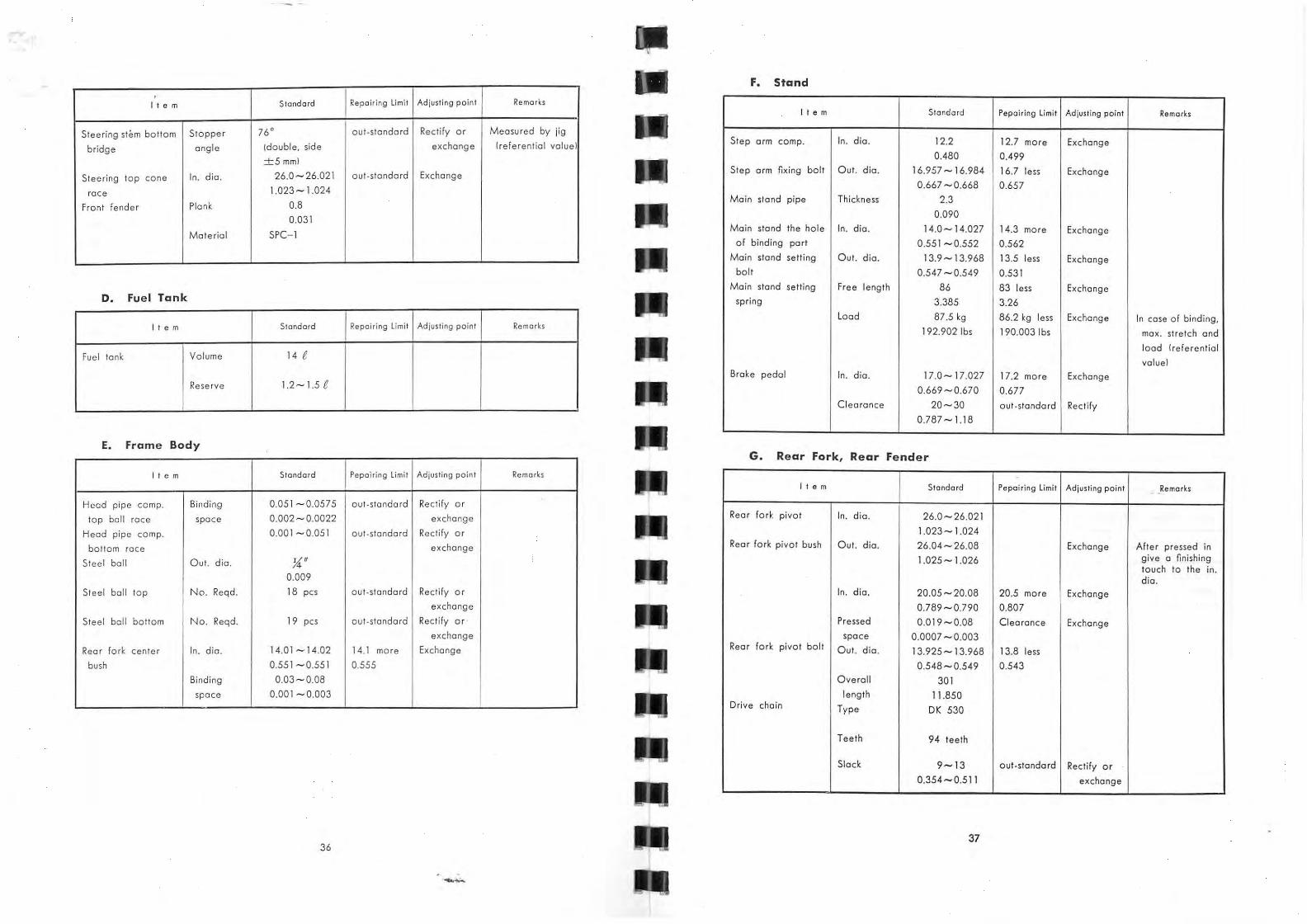
F. Stand • I Repoi,;ng Limit Rem a rks I t e m Standard Adjusting point
It e m Standa rd Pepoiring limit Adjusting point Remorks
Steering stem bo llom Stopper 76° out-standard Rectify or Measured by jig
bridge ongl e (double, side exchange (re ferential va luel
+5mml
Step arm compo In. dio. 12.2 12.7 mo re Exchange
0.480 0.499
Steering top cone In. dio. 26.0 - 26.02 1 oUI-standard Exchange
race 1.023 - 1.024
Front fender Plank 0.8
0.031
Step a rm fixing bolt Out. dio. 16.957 - 16.984 16.7 less Exchange
0.667 - 0.668 0.657 Ma in stond pi pe Thickness 2.3
0.090
Material SPC-l Ma in stand the hole In. dio. 14.0-14.027 14.3 mo re Exchange
of binding par t 0.551 - 0.552 0.562 Main stond sett ing Out. dio. 13.9- 13.968 13.5 less Exchange
bolt 0.547-0.549 0.531 Main stand setti ng Free length 86 83 less Exchange
spring 3.385 3.26 D. Fue l Tank
Load 87.5 kg 86.2 kg less Excha nge In case of binding,
192.902Ibs 190.0031bs max. streich and It e m Standard Repairing limit Adjusting point Remarks
load (referent ia l
value I fuel tonk Volume 14 e
Brake pedal In. dio. 17.0 - 17.027 17.2 more Exchange
0.669 - 0.670 0.677 Reserve 1.2-1.5 e
C learance 20 - 30 ou t·standa rd Rect ify 0.787 -1. 18
E. Frame Body G. Rear Fork, Rear Fender
r t e m Standard Pepairing limit Ad jus ting point Remarks
r t e m Standard Pe poiring limit Adjusting point __ Rema rks
Head pipe camp. Bind ing 0.051-0.0575 ou t·sta nda rd Re ctify o r
top boll ra ce spa ce 0.002 - 0.0022 exchange Rea r fo rk pivot In. dia. 26.0 - 26.02 1
H ead pipe camp. 0.001 - 0.05 1 out·standard Rectify or 1.023 -1.024
bOllom race exchange Rear fork pivo t bush Out. dia . 26.04-26.08 Exchange Afte r pressed in
Stee l boll Out. dia. y.(" 1.025 - 1.026 give a fi nishing tauch to the in.
0.009 dia. Steel boll top No. Reqd. 18 pes out ·s tanda rd Rectify o r In. d ia . 20.05 - 20.08 20.5 mo re Exchange
exchange 0.789 - 0.790 0.80 7 Steel boll bottom No. Reqd. 19 pes out·standa rd Rec tify or Pressed 0.0 19- 0.08 Cl ea rance Exchange
exchange space 0.0007 - 0.003 Rea r fork cente r In. dia. 14.0 1 - 14.02 14.1 mare Excha nge Rear fork pivo t bolt O ut. d ia. 13.925 -1 3.968 13.8 less
bush 0.551-0.551 0.555 0.548 - 0.549 0.543 Binding 0.03 - 008 Overal l 301
space 0.001 - 0.003 length 11.850 D ri ve cha in Type OK 530
Teeth 94 tee th
Sla ck 9 -1 3 o ut· standa rd Rectify or
0.354-0.5 11 exchange
37 36
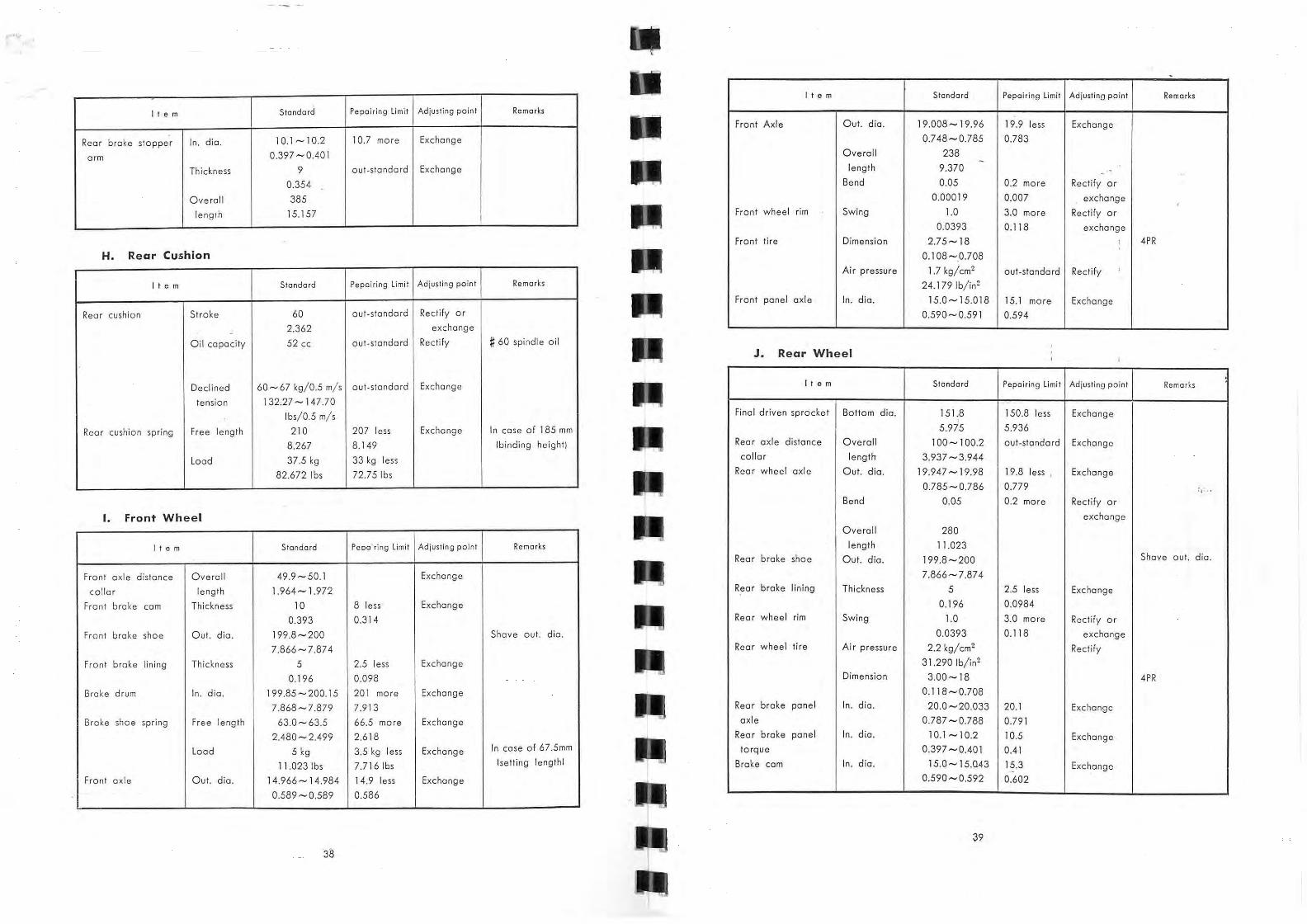
-It e m Sfandard Pepairing Limit Adjusting point Remarks
lie m Standard Pepairing li mit Adjusting poin t Remarks
Front Axle Out. dio. 19.008 -1 9.96 19.9 less Exchange
Rear broke stopper In. dio. 10.1-10.2 10.7 more Exchange 0.748 - 0.785 0.783 O ve ral l 238 -arm 0.397 - 0.40 I
Thickness 9 out-standard Exchange length 9.370 .. -0.354 Bend 0.05 0.2 more Rectify or
Overa ll 385 0.00019 0.007 excha nge
leng Th 15.157 Front wheel rim Swing 1.0 3.0 more Rectify or
0.0393 0.118 exchange
Front tire Dimension 2.75- 18 , 4PR , H. Rear Cushian 0.108-0.708
Air pressure 1.7 kg/em' out-standard Rectify
It e m Standard Pepairing Limit Ad iusting point Remarks 24.179 Ib/in' Front ponel axle In. dia. 15.0 -1 5.018 15.1 more Exchange
Oil capacity 52 ee out-standa rd Rectify # 60 spindle oil J. Rear Wheel
Declined 60 - 67 kg/0.5 m/s oUI-standard Exchange r tern Standa rd Pepairing limit Adjusting point Remarks
tension 132.27 -147.70
Ibs/0.5 m/s Final driven sprocket Bottom dia. 15 1.8 150.8 less Exchange , Rear cushion spring Free length 210 207 less Exchange In case of 185 mm 5.975 5.936
8.267 8.149 (binding height) Rear a xle di stance O ve ral l 100- 100.2 out -standard Exchange
Load 37.5 kg 33 kg less collar length 3.937 -3.944
82.672 Ibs 72.7 5 Ibs Rear wheel axle Out. dia. 19.947 - 19.98 19.8 less , Ex change
0.785-0.786 0.779 c, .. Bend 0.05 0.2 more Rectify or
I. Front Wheel exchange
Overall 280
r tern Standard Peoa'ring limit Ad justing point Remarks length 11 .023 Rea r broke shoe Out. dia. 199 .8 -200 Shove out. dia.
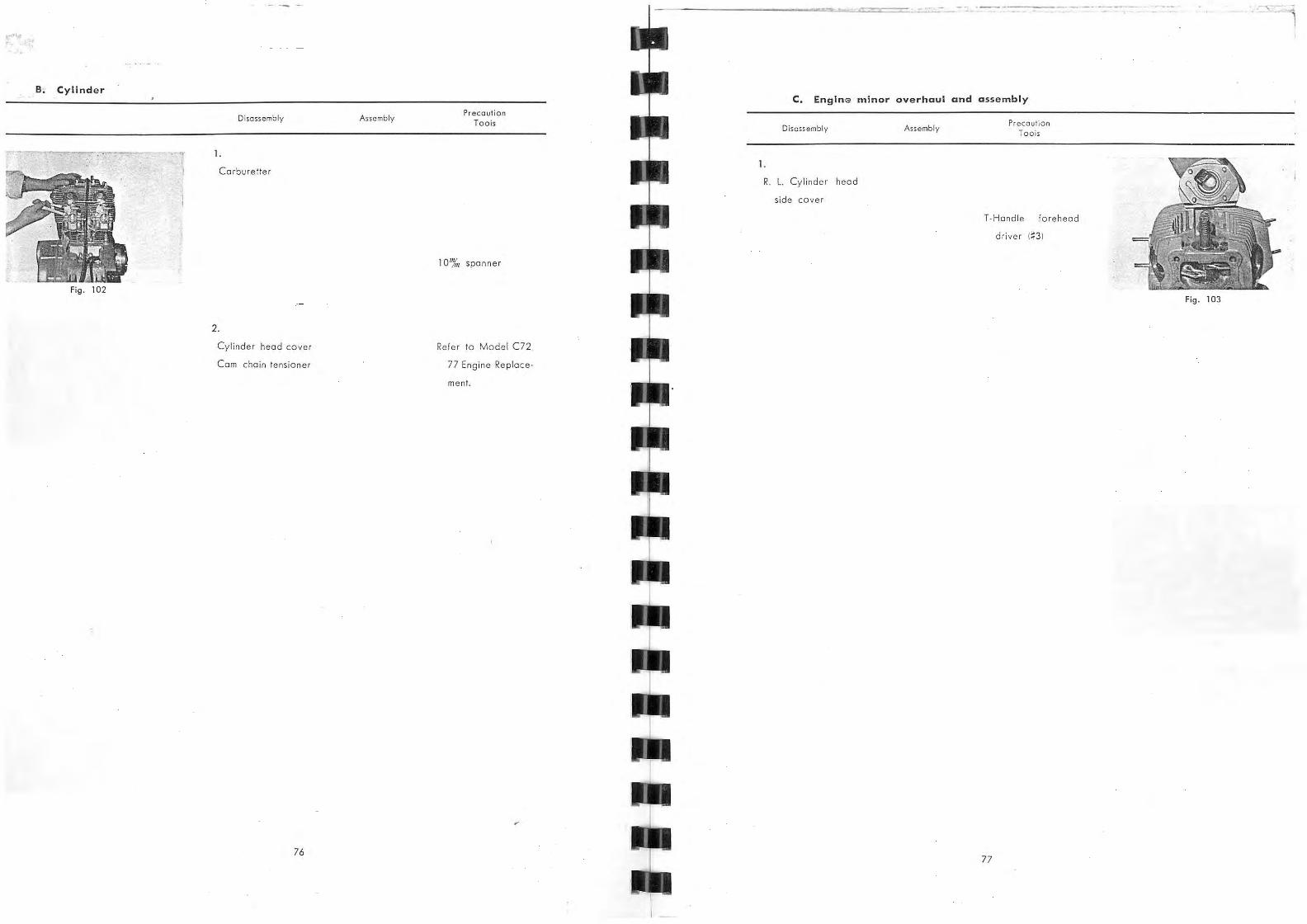
Front axle distance Overall 49.9-50.1 Exchange 7.866-7.874
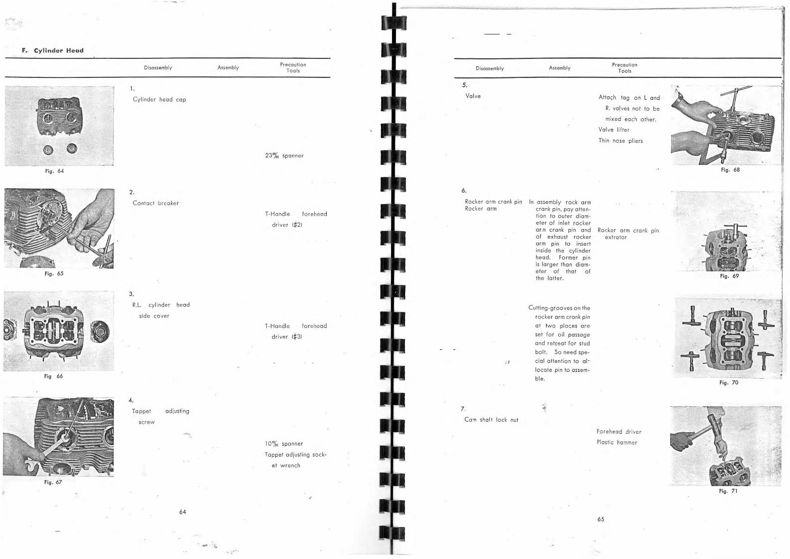
In assembly rock arm cr a nk p in, pay oltention 10 Qute r d iam-ete r of inl et rocker
Precaution Tools
Atla<;h tog on Land
R. val ves not to be
mixed each other .
Valve lifter
Thin nose pl iers
o r .ll cran k pin and Roder arm crank pin of exhaust rocker exira lor arm pin to inse rt inside the cy l inde r head. Forme r p in is large r than diam-eter of that of the latter. Fig . 69
1. POINTS OF CONSTRUCTIONAL DIFFERENCE BETWEEN HONDA
2S0, 300 MODEL C72, 77 AND CB72, 77.
Honda 250. 300 super sport Model CB72. 77 has a newly designed chassis equipped
with engine which partly reconst ructed from those of Model C72. 77. and aimed mainly
to be used as sports car maintaining availability as racer interchanging some of its parts .
As this engine is high rotation. high power type and chassis is light weight. high rigidity
type. the special constructional featurer comparing with Model C72. 77 could be cited
as follow.
A. Engine
1. Twin carburetor
To raise horse power adopted Twin carburetor system removing iunction of suction
manifold.
2. Reciprocating change
Change control system suitable for high speed running and ra cing.
3. Kick of forwa rd step
ConSidering relation with frame. direc tion of step of kick arm was set forward .
4 . 180 degree (I-Type) crank angle
To get stabil ity at high speed reducing vibration left and right crank arm angle was
set as 180 degrees.
B. Frame
1. Frame and rear fork o f steel tub ing
To attain li ght weight and raise rigidity main constructional member is constructed by
high carbon steel pipes.
2. Telescopic type fork
To raise stability at high speed running on rough road maintaining rigidity. Telescopic
type fork was adopted on the fron t wheel suspension.
3. Rear cushion of three step ad justment
Rear cushi on is ad justable according to load and road condition.
4. 1 B inch type
To enlarge bank angle and to help pleasant feeling
front wh eel 2.75- 18. and rear wheel 3.00- 18.
93
on rough road. equipped with
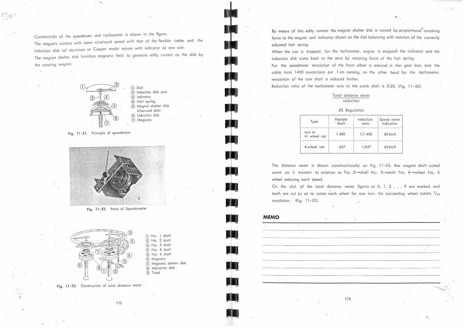
5. Speed . Tachometer
Speedmeter and Tachometer were set in the sam e case.
dl t 0 or interchange 6. Step and han e easy 0 m ve
d 't bl for general, high speed Or race riding. To make easy ri ing posture SUI a e
MEMO
94
2. ENG[NE
A. Main parts of engine
Cylinder and Cylinder Head are th e most important parts of engine and its construction,
material and its machining rote of precision affect engine performance.
Th is type of engine adopted most suitable O. H.V. type valve arrangement to attain effi
cient combustion chamber form. On the other hand the camshaft is set in th e cylinder
head and the valves are actuated by Locker arm 10.H.C), accordingly reciprocating parts
are reduced very much comparing with other types.
CD Contact breake r fitting hole CD Camshaft ® Oil fe lt ® Camshaft ny-wheel ® Breaker arm ® Cam sprocket @ Point @ Va lve rocker arm ® T erminel ® Valve ® Spring ® Piston ® Screw to fix contact point ® Connecting rad ® Contact point ® Cam chain
® Cranksha ft Fig. 2- 1.
95
The cam sooft is driven by chain through the timing gear reductioned 1/ 2 . As the
cylinder head is mode of light alloy, not only it is light but cooling efficiency is ex
cellent as heat conductivity is good, and shope of combustion chamber is idea l semi
spherical one to get efficient combustion of mixture and also to attain larger com
pression ratio.
As the cylinder is machined with high rate of precision cooling efficiency and lubrication are
favorabl e, accordingly wearing effect is very small. Single row W type Needle Bearing
is used at the big end of the connecting rod to get ample loading capacity at the
bearing.
On the other hand single raw Boll Bearings are used on the crankshaft, where W type
middle parts at 2 stations single raw the needle bearing are used to get larger loading
capacity.
As crankshaft has on important function to convert reciprocating motion to rotation,
inertia force due to reciprocating motion of piston and connecting rod should be reduced
. h t t th 01 t 'on The crankshaft can rotate smooth by putting balance w elg t a ge smoo rev u I .
running as it is balanced by dynamic balance on the balancing machine after complete
maching.
To reduce vibration a t high speed revolution and to get stability at high speed running
the right and left cronk arm angle of Model CB72 , CB77-1 crankshaft is set 180 degree.
IFor M odel C72, C77 type angle is 360 degreel
CD
® ® ®
96
Fig. 2 ·2. Type ·1 crankshaft
CD Piston ® Ro lte r bearing ® Connecting rod o R·crankshaft ® 6205 Z speciat ball bearing
® Com chaim sprocket
CD l. crank shaft ® Oil pump drive gear
Fig. 2-3. Type·lt crankshaft
,
B. LUbricating system
Construction and Operation
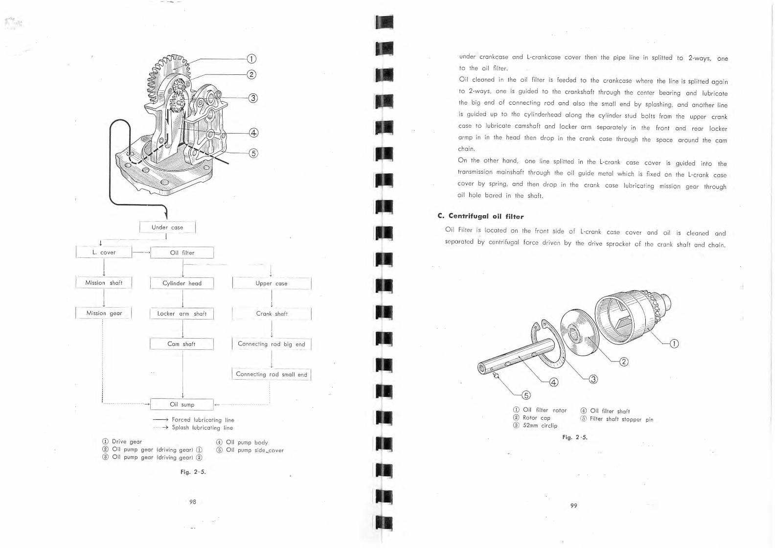
For Hondo 250, 300 oil is supplied under pressure by gear pump and wet-sump
system is applied. The oil pump is attached under crankcase by 6 bolts. The oil
pump is shown in Fig. 2-5 and II I is driving gear and 121 driven gear . Power is trans
mitted by driving gear 131 meshing with crankshaft gear. As for operation of gear
pump, the· driving gear 1 I I rotates to the arrOw direction and the driven gear 121
rotates counterwise, then degree of vacuum increases on the right side sucking oi l
from this side to feed the left side .
Therefore each port of the pump should be carefully inspected to avoid engine
burning or other troubles due to mol lubrication. Such troubles after OCCur due to
oil leakage through inadequate gop between gear teeth and pump main body, or
between gear face and pump body Or pump side cover causing drop of degree of
vacuum .
Lubricating oil sumped in the crankcase is sucked by oil pump to pass through the
Fi g. 2 - 4. Lubricating Circulation
97
,.,,~
I -- l. cover
I
1--~I! ___ O_ il_fi,oI_te_r __ _
I--~--...:! !' Mission ~f-t- I
I Cylind er head Upper case
I __ I_~
I I
Mission gear Crank shaft
I I I !
Cam shaft Connecting rod big end
I !
I Connecti~g rod small end- I
· · ·····- ~I Oil sump l ~- . -» Forced lubricating line ---- 4 Splash lubric ating line
CD Drive gear
® Oil pump gear [driving gead CD ® O il pum p gear Idriving gear I ®
Fig. 2 - 5.
98
@ Oi l pump body ® O il pump sidesover
under crankcase and L-crankcase COver then the pipe line in splilled to 2-ways, One
to the oil niter .
Oil cleaned in the oil niter is feeded to the crankcase where th e line is splilled again
to 2-ways, one is guided to the crankshaft through the center bearing and lubricate
the big end of connecting rod and also the small end by splash ing, and another line
is guided up to the cylinderhead along the cylinder stud bolts from the upper cronk
case to lubricate cam shaft and locker arm separately in the front and rear locker
armp in in the head then drop in the cronk case through the space around the com
chain .
On th e other hand, one line splilled in the L-c rank case cover is guided into the
transmission mainshaft through the oil guide metal w hich is nxed on the L-crank case
cover by spring , and then drop in the crank caSe lubricating mission gear through
oi l hole bored in the shaft.
C. Centrifugal oil filter
Oil Filter is located on the front side of L-crank case COver and oil is cleaned and
separa ted by centrifuga l fo rce driven by the drive sprocket of th e crank shaft and chain.
CD Oi l filter rotor ® Rotor cop ® 52mm ci rcl ip
99
@ Oi l filter shaft
@ Filter shaft stopper pin
3. powm TRANSMISSION
Power transmission is defined such mechanism as rotation of crankshaft. is transmitted
to rear wheel. The first step of transmission from crankshaft to clutch is done by chain.
This clutch is wet multiple plate type, so there is no heat generated by friction and
also no noice perfectly.
As this transmission is such type of advance 4-step and constant meshing, there is no
gear sound while in gear changing, and consequently made it possibl e to wid en rear
wheel driving power of powerful engine.
Further power is transmitted to the rear wheel sprocket by chain drive from the mission,
and through rear wheel dumper of rubber made to the rear wheel sprocket and the
rear wheel torque is transmitted between the final driven flange.
So that torque is transmitted very sm oothly without chain knock getting smooth running.
Especially as clutch is located on th e mission shaft. made it possible to minimize de
deflection of crankshaft and also to stabilize clutch function reducing clutch inertia.
A. Clutch and primary chain
Clutch
f I I Function and kinds
Function of clutch is to cut Or engage power transmission in caSe of changing
gear or starting locating between the engine and the transmission mechanism.
Therefore fineness of cutting and smoothness of engaging and disengaging are im
portant feature.
There are several kinds of clutch system as cone clutch, centrifugal clutch, multi
plate clutch and single clutch, ond w e call wet type when merged in oil and dry
system when oil is not used inside.
f21 Construction and functi on
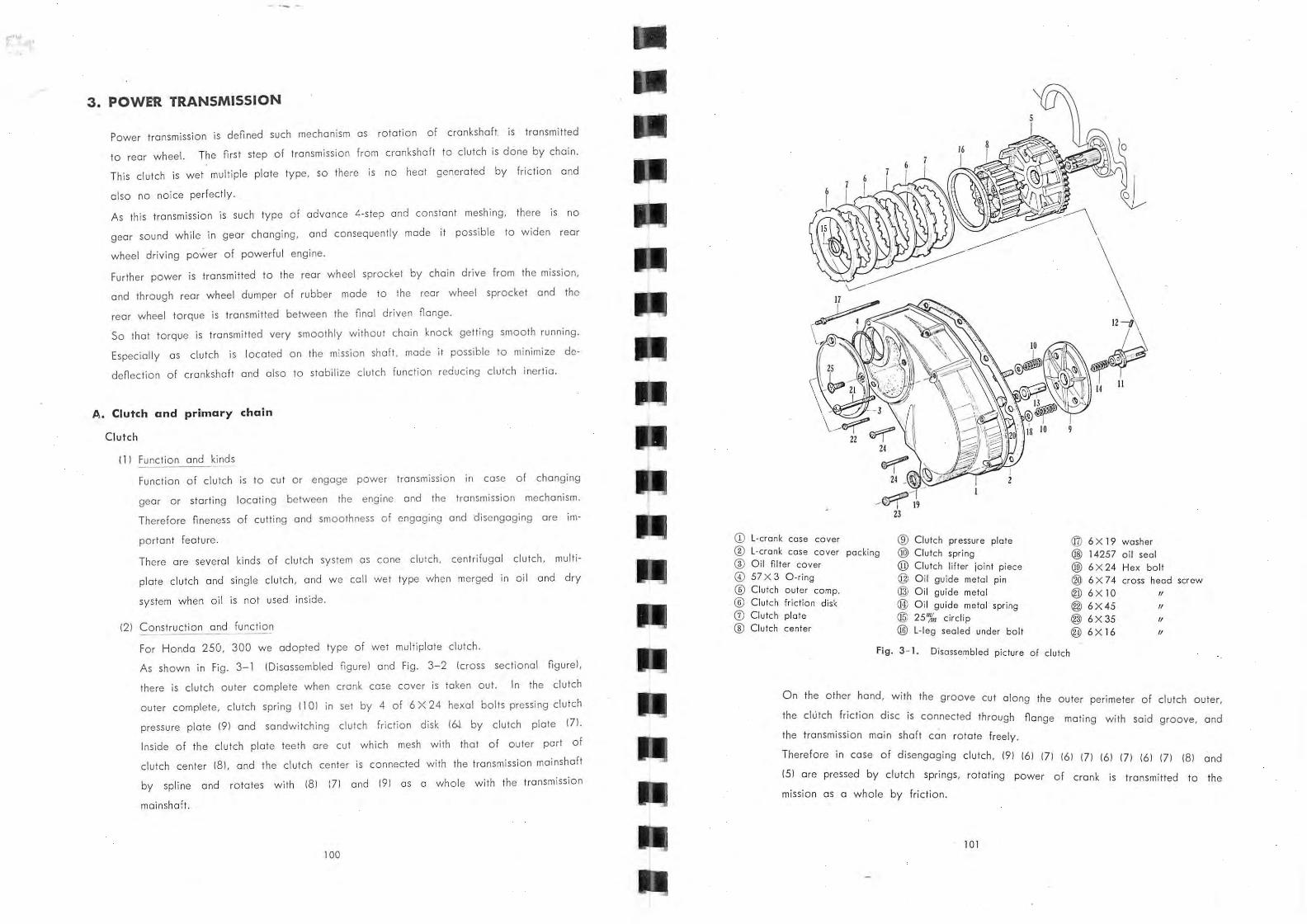
For Honda 250, 300 we adopted type of wet multiplate clutch.
As shown in Fi g . 3-1 IDisassembled fIgurel and Fig. 3-2 leross sectional fIgurel ,
there is clutch outer complete when crank case cover is taken out. In the clutch
outer complete, clutch spring 1101 in set by 4 of 6 X 24 hexal bolts pressing clutch
pressure plate 191 and sandwitching clutch friction disk 16.). by clutch plate 171.
Inside of the clutch plate teeth are cut which mesh with that of outer part of
clutch center 181, and the clutch center is connected with the transmission mainshaft
by spline and rotates with 181 171 and 191 as a whole with the transmission
mainshaft.
100
ill L-cronk case cover ® Clutch pressure plate @ 6X 19 washer ® L-crank case cover packing ® Clutch spring @ 14257 oi l seal ® Oi l filter cover @ Clutch lifter joint piece @ 6X24 Hex bolt 0 57X3 O-ring @ Oi t guide metal pin ® 6X74 head ®
cross screw Ctutch outer compo @ Oil guide meta l @ 6X I O /I
® Clutch fr iction disk ® /I Oil guide metal spring @ 6 X 45 G:l Clutch plate @J 25'%1 circlip @ 6X35 /I
® Ctutch center @ l · leg sealed under bolt @ 6XI6 /I
Fig. 3- 1. Disasse~bled picture of clutch
On the other hand, wi th the groove cut a long the outer perimeter of clutch outer,
the clutch friction disc is connected through fl ange mating with said groove, and
the transmission main shaft can rotate freely.
Therefore in case of disengaging clutch, 191 161 171 161 171 161 171 161 171 181 and
151 are pressed by clutch springs, ro tating power of crank is transmitted to the
mission as a whole by friction.
10 1
(Note )
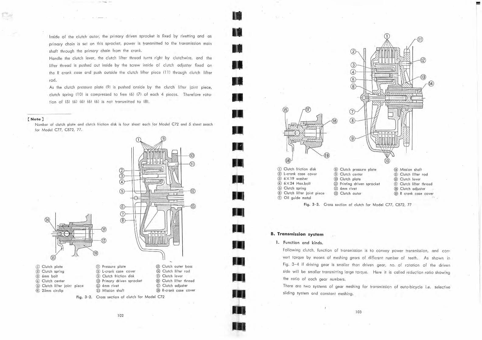
Inside of the clutch outer, the primary driven sprocket is nxed by rivetting and as
primary chain is set on this sprocket, power is transmitted to the transmission main
shaft through the primary chain from the crank.
Handle the clutch lever, the clutch lifter thread tUrns right by clutchwire, and the
lifter thread is pushed out inside by the Screw inside of clutch adjuster nxed on
the R crank case and push outside th e clutch lifter piece II II through clutch lifter
rod.
As the clutch pressure plate 191 is pushed onside by the clutch lifter joint piece,
clutch spring I I 01 is compressed to free 161 171 . of each 4 pieces . Therefore rota
tion of 151 161 161 161 161 is not transmitted to 181 .
Number of dutch plate and clutch friction disk is four sheet each for Model el2 and 5 sheet seach
for Mode l Cll, CB72, 77.
CD Clutch plate ® Clutch spring ® 6mm bolt @ Clutch center ® Clutch lifter joint piece
CD Clutch friction disk ® Clutch pressure plate ® Mission shaft ® L-crank case cover ® Clutch center @l Clutch lifter rod ® 6X 19 washer ® Clutch pla te ® Clutch lever @ 6X24 Hex.bo lt @ Pr inting driven sprocket ® Clutch lifter thread
® Clutch spring @ 6mm rivet @ Clutch adiuster ® Clutch lifter jOint piece @ Clutch outer @ R crank case cover
CD Oil guide metal ...
Fig. 3- 3. Cross section of clutch for Model Cll. CB72, II
B. Transmission system
1, Function and kinds ,
Following clutch, function of transmission is to convey power transmission, and con~
vert torque by means of meshing gears of different number of teeth. As shown in
Fig. 3-4 if driving gear is smaller than driven gear, no. of rotation of the driven
side will be smaller transmitting large torqu e. Here it is called reduction ratio showing
the ratio of each gear numbers.
There are two systems of gear meshing for transmission of auto-bicycle i.e. selective
sliding system and constant meshing.
103
•
.•..
o
Driven gear INa. of teeth BI
o
Drive gear INa. of teeth AI
A Reduction rat io = -
B
Torque ratio = ~ A
Fig. 3-4. Relation between reduction ra tio and torqu e ratio
By selective sliding system, shift gea r is slided by gear shift fork to get adequate
reduct ion rat io by changing gear to be meshed, and by constant mcshing system,
each gear can be rotated freely always each -gear in meshing state, and can be
changed reduction ratio by actuating optional gear by means of special clutch.
Fig. 3 - 5. Cro~s sectiona l figure of transmission gear
2. Construction and Function
The transmission system of Honda 250 · 300 is constant mesh and advance 4 stage rotary
type. In Fi g. 3-5 to Fig . 3-9, neutral, nrst, second, third and top stage are shown.
Fu nction of transmission as shown in Fig. 3- 5 and Fig . 3- 10 is as follows, i.e . power
104
is transm itted from crank shaft to primary drive chain, clutch outer, clutch center and
transmissi on.
Explaining in
mission shaft
Fig. 3- 6. The first
Fig . 3- 7. The second
order, from the crank rotation is
is ro tated to turn the low gear (71.
transmitted to the clutch , and the
The low
the kick-starter spindle 1191. As the coun ter shaft 2 gear
gear turns sl iding over
191 which is connected
105
with the spline on the counter shaft complete can move freely axially, move this to., ·~'::.·::~· the left ' side by gear shift fork to mate with 100" gear IFig. 3-61 then the low gea/ :';':
combines with the counter shaft as one body to transmit power to the top gear (121.
Here the axial movement of main shaft gear is restricted by the gear cotter (141 and
the set ring (151 but not restricted rotationally. (similarly counter shaft 3 gear (111.1
Fig. 3- 8 . The third
Fi g. 3- 9. The fourth ITopl
106
Fig. 3- 10.
CD 14'%1 bush ® Kick spind le meta l bush ® Clutch lifter rod complete @ 12.8 X 2.2 "0" ring ® Transmission main shaft ® Counter shaft 120TI (j) l ow gear complete
0. Main shaft 2·gear ® Counter shaft 2-gear @ Main shaft 3-gear @ Counter shaft 3-gear @ Top gear complete
Similarly for the second, protrusion of main shaft 3 gear (101 combine with that of
mainshaft 2-gear 181 by actuating another shift fork, and power is transmitted by
rotating mainshaft 2-gear (81 connected by protrusion with mainshaft 3-gear (101
mounted on the spline of mainshaft transmitting to countergear (31 and by spline from
counter shaft to the top gear .
As for the third, protrusion of counter shaft 2 gear (91 combine with that of counter
shaft 3 gear (Ill to transmit power to the top gear (121 through counter shaft (61.
And for the Top, mainshaft 3 gear (101 combine with the protrusion of the top gear
and rotation of mainshaft is transmitted straightly to the drive sprocket to drive the
drive-chain. As for the neutral, each protrusion is not combined so power is not
transfer to the top gear.
Other parts of the kick starter system are kick spindle pawl (201 and kick spindle
pawl spring (211. This pawl mates with the inside groove of the low gear to rotate '
low gear. When not kicked, the head part of this pawl is pushed by protruded part
inside crank case, and pawl is pulled in to free the gear.
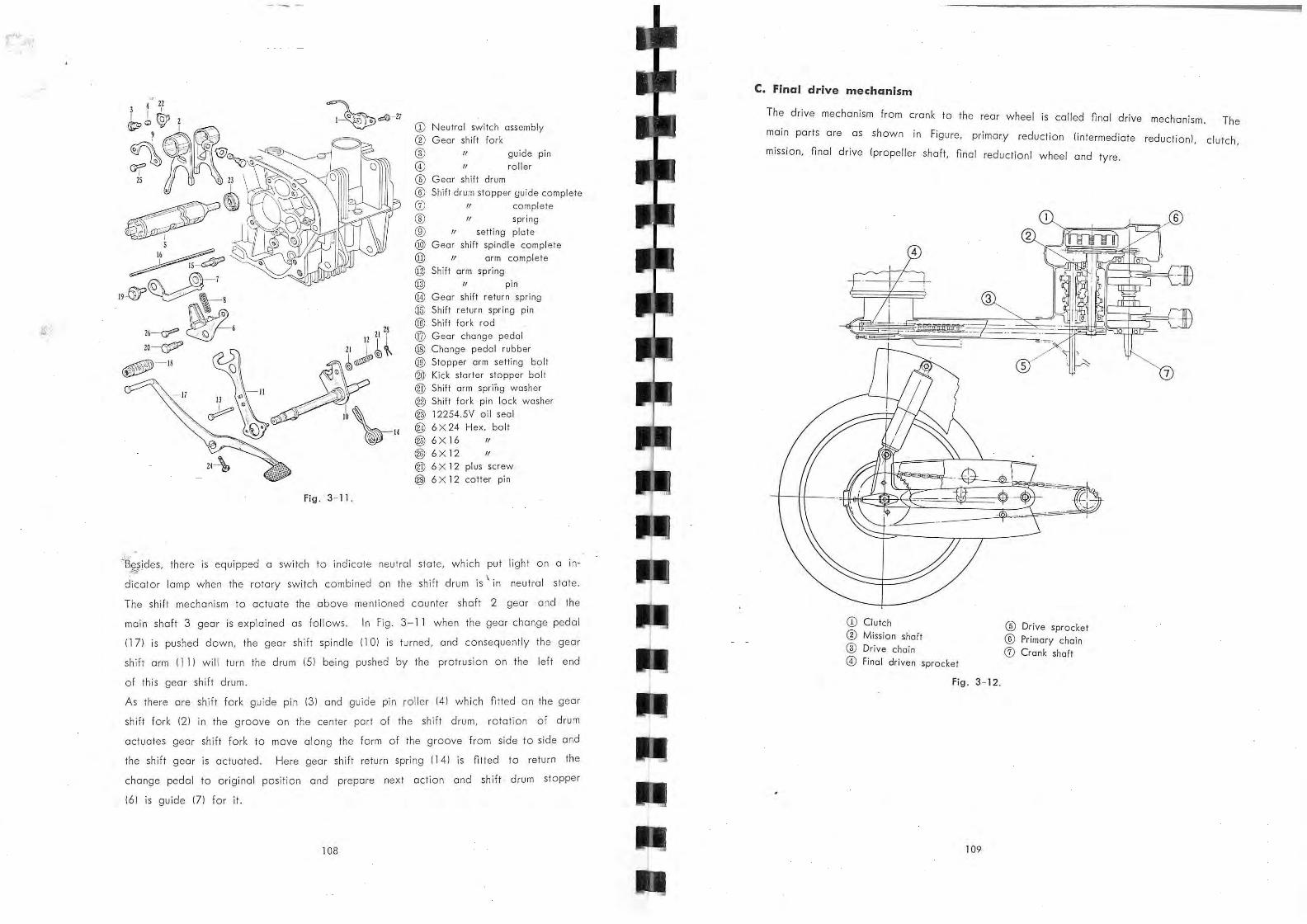
Fig . 3- 11.
CD Neutral switch assembly
® Geor shift fork
® o
/I
® Gear shift drum
guide pin
roll er
® Shift drum stopper guide complete
CD ® ® ®
/I complete
1/ spr ing
1/ setting plate
Gear shift spindle complete
@ " arm complete @ Shift arm spring
@ 1/ pin
@ Gear shift return spring
@ Shift return spring pin
® Shift fork rod @ Geor change pedol @ Chonge pedol rubber @) Stopper arm setting bolt
@ Kick starter stopper bolt @ Shift arm spring washer
@ Shift fork pin lock washer @ 12254.5V oil seal @ 6 X 24 Hex. bolt @ 6X16 /I
@ 6X12 /I
@ 6X 12 plus screw @ 6 X 12 coller pin
~'B~~ides, there is equipped a switch to indicate neu tral state, which put light on a in
dicator lamp when the rotary switch combined on th e shift drum is \ in neutral state.
The shift mechanism to actuate the above mentioned counter shaft 2 gear and the
main shaft 3 gear is explained as follows. In Fig. 3-11 when the gear change pedal
1171 is pushed down, the gear shift spindle 1101 is turned, and conseque:ltly the gear
shift arm 1111 will tUrn the drum 151 being pushed by the protrusion on the left end
of this gear shift drum.
As there are shift fork guide pin 131 and guide pin roller 141 which fitted on the gear
shift fork 121 in the groove on the center part of the shift drum, rotation of drum
actuates gear shift fork to move along th e form of the groove from side to side and
the shift gear is actuated. Here gear shift return spring 1141 is fitted to retu rn the
change pedal to original position and prepare next action and shift drum stopper
161 is guide 171 for it.
108
C. Final drive mechanism
The drive mechanism from crank h to t e rear wheel is called final drive mechanism. The
main ports are as shown in Figure, primary reduction /intermediate reduction), clutch,
mission, final drive Ipropeller shaft, final reductionl wheel and tyre.
CD Clutch ® Mission shaft
® Drive chain
o Final driven sprocket
Fig . 3- 12.
109
® Drive sprocket
® Primary chain
CD Crank shaft
.,~
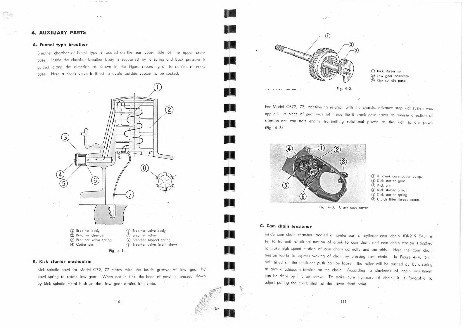
4. AUXll,lARY PARTS
A. Funnel type breather
Breather chamber of funnel type is located an the rear upper side of the upper crank
case. Inside the chamber breather body is supported by a spring and back pressure is
guided along the direction as shown in the Figure separating oil to outside of crank
case. Here a check valve is fitted to avoid outside vapour to be sucked.
2
3
5
fI- --{ 7
a;J Breather body ® Breather valve body @ Breather chamber ® Breather valve
® Breather va lve spring <V Breather support spring
® Cotter pin ® Breather valve (plain view)
Fig . 4- 1.
B. Kick starter mechanism
Kick spindle pawl for Madel C72, 77 mates with the inside groove of low gear by
pawl spring to rotate low gear. When not in kick, the head of pawl
by kick spindle metal bush so that low g ear attains free state.
110
is pressed dawn
Fig . 4- 2.
CD Kick starter spin
® l ow gear complete
® Kick spindle pane l
For Model CB72, 77, cons idering relati on with the chassis , advance step kick system was
applied. A piece of gear was set ins ide the R crank case cover to reverse direction of
rotati o n and can start engine transmitting rotat ional power to the kick spindle pawl.
IFig . 4-31
Fig . 4 - 3 . Cronk case cover
C. Cam chain tensioner
ill R. crank case cover compo ® Ki ck storter gear
® Kick arm @ Kick starter pinion
® Kick storter spring
® Clutch lifter thread compo
Inside cam chain chamber located at center part of cylinder cam chain IOK219-94L1 is
set to transmit rotat iona l motion of crank to cam shaft, and cam chain tension is applied
to make high speed motion of cam chain correctly and smoothly. Here the cam chain
tension works to supress waving of chain by pressing cam chain. In Figure 4-4, 6mm
bolt fitted on the tensioner push bar be loosen, the roller will be pushed out by a spring
to give a adequate tension on the chain. According to slackness of chain adjustment
can be done by this set SCrew. To make Sure tightness of chain, it is favorable to
adjust putting the crank shaft at the lower dead paint.
11 1
.,
3
4
Fig. 4 - 4 .
CD Cam sprocket ® R cam shaft ny wheel ® Cam chain tensioner
CD Cam chain tensioner ® Com chain tensioner spring
® T ensioner hold er @ 6mm bolt ® Cam chain tensioner push bar
® Cam chain tensioner orm
@ Cam chain ® Cam chain guide ro ll er
® Center crank shaft
Fig. 4- 5.
112
5. CARBURETTOR
The carburettar is a device for supplying fuel and ai r into the engine. The performance
of the carburet o r w ill depend upon such factors as most suitable mixture proportion
of atomized fuel under all conditions of speed and load of the engine. Therefore it
must has precision for each port and high resistance for wear to aSSure th e reliable
performance for a long period, and so it is required inspection and maintenance.
Th e revised ports of Model C72 from Model C7 1 are as fo ll ow.
11 I Elimination of manifold .
121 Fitting type Down Draft type.
131 Addit ion of power jet.
Comparing Model CB72, 77 with Model C72, 77 2-ca rburettor system was adopted to
increase Horse power by eliminating branch to sucti on pos t. Concerning the power
jet mentioned above, when MJ., # is set, the best condition is a t 4000 rpm, and at
8000 rpm mixture becomes thin, but when MJ 0 # is set at 8000 rpm th e best and at
4000 rpm becomes rich.
Therefore to get favo rable conditi on between 4000 rpm and 8000 rpm, MJ., # was
selec ted to apply th e power jet from 6000 rpm to meet high rotation developing per
formance at med ium and high power.
Fig . 5 - 1. Power iet system
113
CD Power iet ® Blind plug ® Power air iet
Consfructiqn
III Air from the air cleaner passes through the suction port Ill, lower side of the throttle
valve 161, main bore IBI and into the cylinders.
This air stream produces a partial vacuum in the area around the power nozzle 1241,
by which fuel in the noat chamber 121 nows through power jet fuel pipe 1231, power
jet 1221 to the power nozzle 1241. At this area, fuel is mixed with air introduced
through the power air jet 1211. Then they are mixed with air nowing from the suction
port, vaporized and drawn into the cylinder IFig. 5-21.
121 Main Fuel system.
Air from the air cleaner passes through the suction port Ill, lower side of the
throttle valve 161 main bore IBI and into the cylinders. Th is air stream produces a
partial vacuum in the area around the needle jet 141, by which fuel in the noat
chamber 121 nows through the main jet 1101 into the needle jet holder 131. As this
area, fuel is mixed with air Ibleed airl introduced through the air jet 151 and the
holes 191 provided around th e needle jet holder 131. Then fuel and air travel the
gap between the needle jet 141 and the jet needle 171. and discharge to the lower
side of the throttle valve. Th en they are mixed with air nowing from the suction
port, vaporized and drawn into the cylinder IFig. 5-21.
131 Slow speed fu el system Ipilot systeml.
Air from the suction part III passes through the outside 1121 of the air Screw 1111
which regulates the rate of air now. Th en air passes through the bleed holes 1141
of the slow speed jet 1131 to th e slow speed jet 1131 where introduced into fuel
stream from the orince 1151 provided with the bottom of the slow speed jet 1131.
The rich mixture produced at this area discharges to the lower side of the throttle
valve and is mixed with air nowing from the suction port III and drawn into th e
cylinder. The minar mixture adjustment is made by means of the air screw 111 1.
Turn the air screw to the right to enrich the mixture and to the left to lean the
mixture . The major mixture adjustment is made by replacing the slow speed jet 1131.
Replace the jet with one carrying bigger number to enrich the mixture and with one
carrying smaller number to lean the mixture IFig. 5-21.
141 Fl oat chamber
The carburetor must supply the correct mixtures which suit to th e throttle opening and
the engine running speed. .In this connection, the fuel level must be held constant.
The noat system is a device to maintain this constant height. The operation of the
noat system is given in the following. Fuel from the tank enters the noat chamber
114
121 through the passage 1161, the valve seat 1171 and valve I1BI . As fuel enters the
noat chamber, the noat 1191 will raise and move the valve I1BI upperward by
means of the noat arm 1201. When the valve touches the valve seat, now of fuel
will be restricted. As fuel level drops,
fuel to enter the noat chamber. Thus,
the noat lowers, opening
any change in the fuel
the valve to allow
level caUSes a (Or-
responding movement of the noat, opening Or closing the valve to maintain the fuel
level constant. There is a spring installed, against vibration, between the needle
valve and its body at th I . h e ocatlon were the valve contracts the noat arm 1201.
IFig. 5-21.
151 Choke system
The choke valve 1211 must be in a closed posit ion with the choke lever moved up
wards, and in a open position with the choke lever moved downward, as shown in
Fig. 5-2.
Fig. 5-2.
115
161 Adju~tment
01 High speed Fuel mixture adjustment
Fuel mixture between full and half open throttle positions is controlled by the
main jet. To determine whether the main jet is correct, slightly close the choke
valve with the engine running at full throttle.
1. If the engine speed increases, the fuel mixture is too leon.
2. If the engine speed decreases, the main jet in correct Or too big .
Replace the main jet as necessary ' in such caseS,
bl Moderate speed Fuel mixture adjustment.
Fu el mixture between half and one eighth throttle positions is controlled by the
adjustable jet needle and cut away of throttle valve.
1. If the muffler is block smoking, th e mixture is too rich. Lower the jet needle
to the next lower position.
2. If the engine misnres Or hesitates when accelerated or driven at moderate
speed, the mixture is too leon. Raise the jet needle to the next upper position.
The throttle valve cut away carrying larger number bring the mixture leaner while
one carrying smaller number bring the mixture rich er. Since the change on th e
cutaway affects the engine performance below one eighth throttle position, the
replacement of the throttle valve should be done carefully.
cI Low speed Fuel mixture adjustment.
Fuel mixture between one eighth and idle throttle positions is controlled by the
air Screw and throttle cut away.
1. Adjustment must be done by the air Screw mostly. Turn the air screw " in"
to enrich the mixture and "Out" to leon the mixture.
2. If the correct adjustment cannot be obtained by the turning of air screw,
replace the throttle valve.
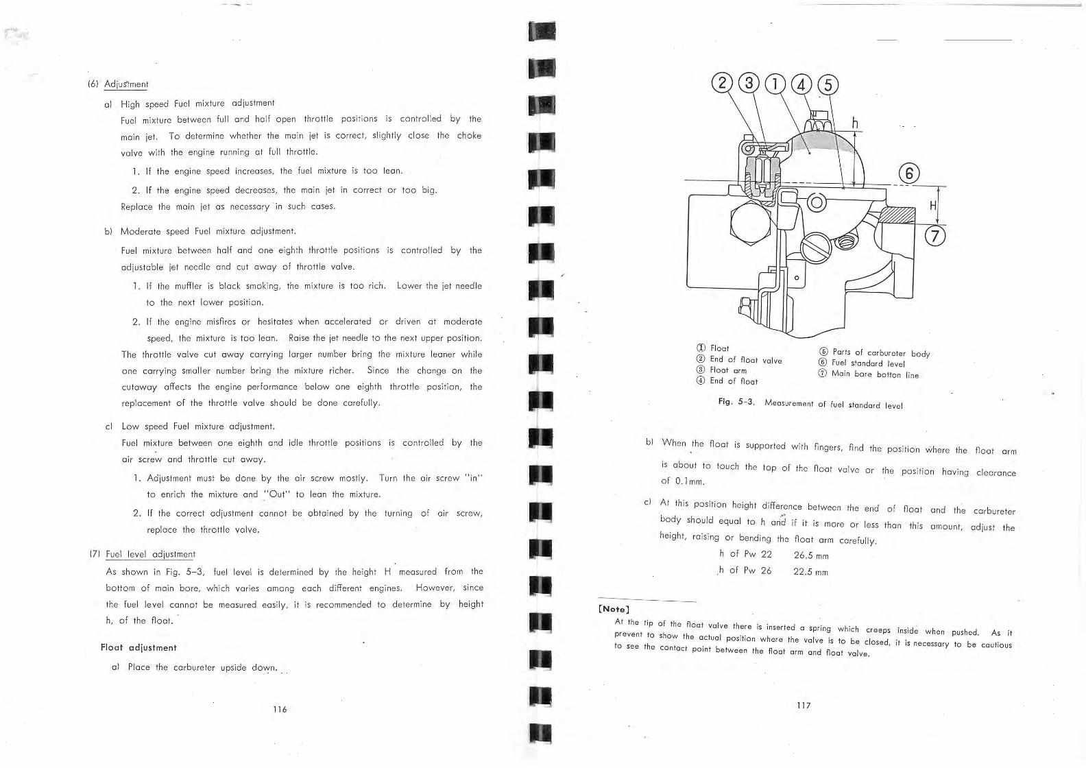
171 Fuel level adjustment
As shown in Fig. 5-3, fuel level is determined by the height H measured from the
bottom of main bore, which varies among each different engines . However, since
the fuel level cannot be measured easily, it is recommended to determine by height
h, of th e noat.
Float adjustment
01 Place the carbureter upside down.
116
/
(Note]
CII Float ® End of float valve ® float arm
o End of float
~~~~~~----
® Ports of carbureter body ® fuel standard level Ci) Main bore botton line
Fig. 5 - 3. Measurement of fuel stondard level
bl When the noat is Supported with nngers, nnd the position where the noat arm
cl
is about to touch the top of the n oat valve or t.he position having clearance
of 0.1 mm.
At this position height diff.erence between th e d en of noat and the carbureter
body should equal to h arid if it ',s mOre Or less than this amount, adjust the height, raiSing Or bending the noat arm carefully.
h of Pw 22
h of Pw 26
26.5 mm
22.5 mm
At the tip of the float valve there is inserted a spring h t w ich creeps inside when pushed. As it
preven to show the actual position where the valve is t h to be dosed, it is necessary to be cautious Osee f e contact point between the float arm and float valve.
11 7
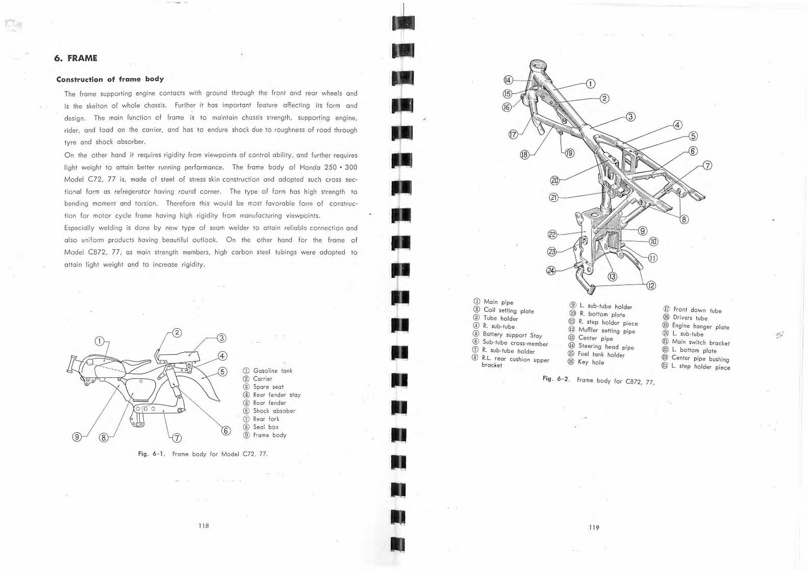
6. FRAME
Construction of frame body
The frame supporting engine contacts with ground through the front and reor wheels and
is the skelton of whole chassis. Further it has important feature affecting its form and
design. The main function of frame is to maintain chassis strength, supporting engine,
rider, and load on the carrier, and has to endure shock due to roughness of rood through
tyre and shock absorber.
On the other hand it requires rigidity from viewpoints of control ability, and further req ui res
light weight to attain better running performance. The frame body of Hondo 250 • 300
Model C72, 77 is, mode of steel of stress skin construction and adopted such croSs sec
tionGI form as refregerato r having round corner. The type of form has high strength to
bending moment and torsion. Therefore this would be most favorable form of construc
tion for mo'tor cycle frame having high rigidity from manufacturing viewpoints.
Especially welding is done by new type of seam welder to attain reliable connection and
also uniform products having beautiful outlook. On the other hand for the frame of
Model CB72, 77 , as main strength members, high corban steel tubings were adopted to
attain li ght weight and to increase rigidity.
2
CD Gasoline tank ® Corrier
@ Spare seat ® Rear fender stay ® Reor fender
QD Shock obsober CV Rear fork ® Seal box ® Frome body
Fig . 6 - 1. Frame body for Model C72, 77.
118
/
CD Main pipe @ Coil sett ing plate @ Tube holder o R. sub-tube
® Battery support Stay ® Sub-tube cross-member
CV R. sub-tube ho lder '8' R.l . rear cushl'on \V upper
bracket
® l . sub·tube holder @ R. bottom plate @ R. step holder piece @ Muffler setting pipe @ Center p ipe
@ Steer ing head pipe @ Fuel tonk ho lder @ Key ho le
Fig. 6- 2 . Frome body for CB72, 77.
119
@ Front down tube @ Drivers tube
® Engine hanger plate ® l. sub-tube
@ Main switch bradet @ l . bottom plate @ Center pipe bushing
®> l. step holder piece
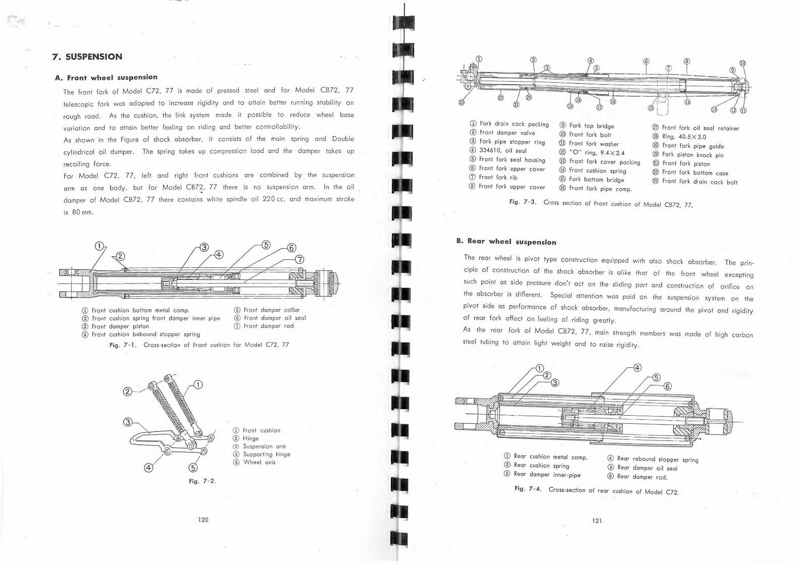
7 . SUSPENSION
A. Front wheel suspension
C 2 77 ,'s made of pressed steel and for M odel CB72, 77 The front fork of Model 7,
. 'd' t d to attain better runn ing stability on telescopic fork was adopted to increase rig, 'yon
rou gh road . As the cushion, the li nk system made it possible to reduce wheel base
variation and to attain better feeling on riding and better controllability.
of sh ock abso rber, it consists o f the main spring and Double As shown in . th e Figure
cylindrica l oil dumper. The spring takes up compression load and the damper takes up
recoi l ing force .
h f h' are combined by the suspension For M odel C72, 77 , left and rig t ron t cus ,ons
arm as one body, but for M odel CB72, 77 there is
damper of Model CB72 , 77 there contains wh i te spindle
Fork drain cock packing ® Fork top br idge @ Front fork oi l sea l retainer Fron t damper va lve ® Front fork bol t @ Ring, 40.5 X 3.0 fork pipe stopper ring @ front fork washer @ Front fork pipe guide
@ 3346 10, oil seal @ "0" ring, 9.4 X 2.4 ® Fork piston knock pin ® front fork sea l housing @ front fork caver packing @ Front fork piston ® Front fork upper cover @ Front cushion spring @ Front fork bottom case (j) Fron t fo rk rib @ Fork bottom bridge @ Front fork drain cock bolt ® Fro nt fork upper cover @ Front fork pipe compo
f ig . 7- 3. Cro ss section of Front cu shion of Model CB72. 77.
B. Rear wheel suspension
The rear wheel is pivot type conslruct ian equipped wilh also sh ock absorber. The prin
ciple of conslru cl ian of the shock absorber is alike Ihal of the front wheel excepling
such point as side preSSure don' l act on Ihe sliding part and construclio n of orifice on
Ihe absorber is differenl. Special a llenlion was pa id On the suspension syslem on Ihe
pivot side as performance of sh ock absorber, manufacluring around the pivot and rigidity
of rear fork affec l on feeling of riding greatly.
As Ihe rear fork o f Model CB72, 77 , main slrength members was made of high carbon
steel lubing to attain light weight and 10 raise rigidity.
CD Rear cushion metal compo @ Rear rebound sto pper spring ® Rear cushion spring ® Rear damper oi l seal ® Rear dam per inner-pipe ® Rear damper rod,
Fig . 7- 4. Cross-section of rear cushion of Model C72.
@) Rear cushion spring adjuster @ Rear damper inner- pipe
Fig . 7- 5. Cross-section of rear cushion of Model CB72, 77.
In the cylind er of the rear cushion th ere contains 60~ spindle oil 37 cc for Model C72,
77 and 47 cc for Model CB72, 77. When the rear wheel got shock rear cushion spring
is compressed to absorb it and rebounding force is restricted by the oil damper to give
adequate cushioning.
If the amount of oil contained in the damper is not su itable, effective stroke of . cushion
becomes to short or leaks oil Or sometimes become origin of shock sound. The rear
cushion of Model CB72, 77 is deSigned to enable three steps of adjustment according
to road cond ition and running stote.
MEMO
122
8 . STEERING SYSTEM
A. Steering handle
Special attention was paid in designing the Steering Handle as this affect feeling of riding
and easy control.
Especially for Model C72, it was aimed to toke riding posture easy to correspond quick
manipulation of control, wh;'ch would be determined by the form of the handle, saddle
and step. Moreover on control ports , adjustment equipments are attached according to
each riders' choice. These features could be said to symbolize Hondo 's kindness.
11
CD L. front winker lens (f) R. steering handle lever ® L steering handle lever ® Throttle wire (j) H orn button ® Winker switch 0) H ead light switch @ R. grip rubber @ L. grip rubber @ Throttle lever ® R. front winker lens
Fig . 8- 1 Handle of Model en, 77.
The handle complete of Model CB72, 77 ,'s mode of One p,'ece f a steel tubing attached
to the fork top bridge by means of the handle pipe holder. The fork top bridge is
fixed on the front cush,'on by 2 front fork bolts. E h ac wire is exposed in assembly to make it easy to replace the hand le.
123
CD ® ,
CD Speedo-Tackometer ass'y
® ® Steering handle comp o
(3) Hondle pipe holder
0 Steering damper knob
.Fig . 8- 2. Handle assembly of Model CB72, 77.
B. Steering
Construction of steering of Model C72, 77, as shown in the Figure, is such having ball
bearing and steering damper 01 friction plate system to meel requiremenl from conlral
labilily and slability 01 low and high speed running.
For Model CB72, 77, the steering stem which has cone lathe inside supported on the
front cushion by means of 8 X 32 hexagonal bolt is the rotational axis centering frame
head pipe and is important part for steering. On the steering stem, steering damper is
attached and can be adjusted according to road condition, runn ing state and loading
condition.
If th e knob of steering damper be turned to the right, steering damper spring nut is
raised upward to cramp steering damper friction disk by means of steering damper plate
A and B, consequently handle steering becomes heavy. On the contrary, if the knob
be turned to the left, steering damper spring nut is lowered to make gap between plates
A and B to become easy steering. IFig . 8-41
CD Steering damper knob compo ® Damper lock spring set bolt
® Steering damper lock spring
@ Steering head stem nut ;
; ® Fork top bridge
F· 8 3 Crass section of steering head of Model C72, 77 . • g . - .
124
® Steering top thread
CD Steering bottom cone rcce
® Steering head dust seal
® Steering damper friction disk
@ Steering damper plote B
@ Steering damper spring
@ Cotter pin, 2.0 X 15 @ Steering top cone race
@ Steel boll, 1/4" @ Steering top ball race
@ Steering head pi8e @ Steering stem y @ Steering bottom boll roce @ Steel boll, 1/4" @ Steer ing domper plote A @ Steering damper lock nut
@ Steering damper spring nut
Fig. 8 - 4. Cross section of steering of Model CB72, 77.
125
~ ... ,
9. BRAKE .INSTALLATION
As reliability and durability of Brake installation ore indispensable cond,tion for it, manu
facturing Brake was paid special attention. Reor wheel braking is done by expanding
the brake lining installed is the brake drum which is actuated by link motion to tUrn
the brake cam by pushing right foot.
Here special attention was paid to disci pate fr icti on heat generated to get better dura
bility. For the fro nt brake, by right hand operation wire transmits force to work and
brake machanism is alike with the rea r Installation.
3
-CD Broke Cam ® Brake lining
Fig . 9 - 1.
Fig. 9- 2
126
@ Brake drum
CD Brake ® Brake @ Brake
0 Brake
® Broke
/
shoe width 30 shoe onker pin
drum inner dio
shoe out dio
cam
6
® Front fork
Fig . 9-3.
MEMO
12 7
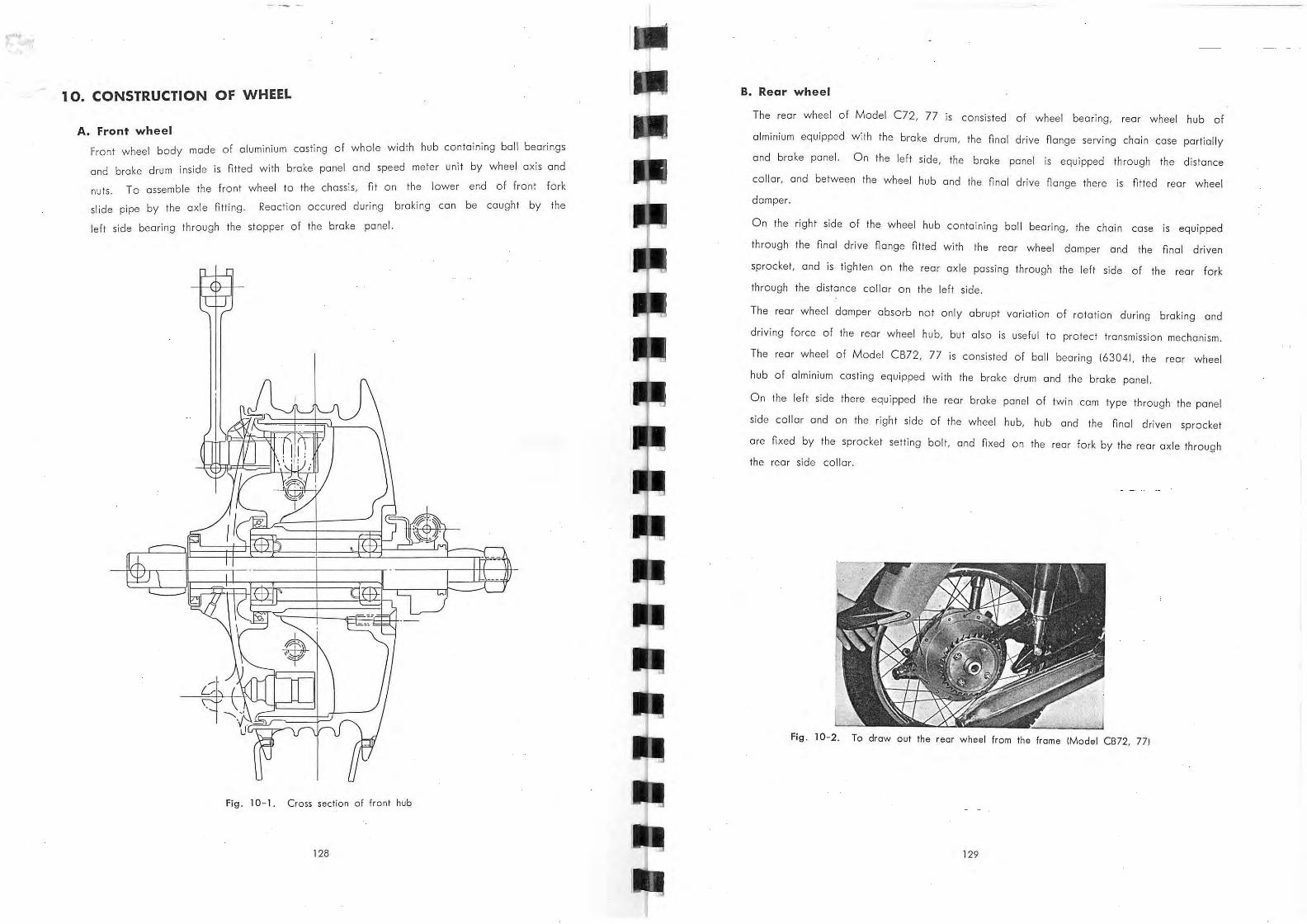
10. CONSTRUCTION OF WHEEL
A. Front wheel
cast 'lng of whole width hub containing ball bearings Front wheel body made of aluminium
and brake drum inside is fitted with brake panel and speed meter unit by wheel axis and
nuts. To assemble the front wheel to the chassis, fit on the lower end of front fork
fi React ion occured during braking can be caught by the slide pipe by the axle Itting.
left side bearing through the stopper of the brake panel.
Fig. 10 - 1. Cross section of front hub
128
B. Rear wheel
The rear wheel of Model C72, 77 is consisted of wheel bearing, rear wheel hub of
almin ium equipped with the brake drum, the final drive nange serving chain case partially
and brake panel. On the left side, the brake panel is equipped through the distance
collar, and between the wheel hub and the final drive nange there is fitted rear wheel
damper.
On the right side of the wheel hub containing ball bearing, the chain case is equipped
through the final drive nange fitted with the rear wheel damper and the final driven
sprocket, and is tighten on the rear axle passing through the left side of the rear fork
through the distance collar on the left side.
The rear wheel damper absorb not only abrupt variation of rotation during braking and
driving force of the rear wheel hub, but also is useful to protect transmission mechanism.
Th e rear wheel of Model CB72, 77 is consisted of ball bearing 163041, the rear wheel
hub of alminium casting equipped with the brake drum and the brake panel.
On the left side there equipped the rear brake panel of twin cam type through the panel
side collar and on the right side of the wheel hub, hub and the nnal driven sprocket
are fixed by the sprocket setting bolt. and nxed on the rear fork by the rear axle through
the rear side collar.
Fig. 10-2. To draw aut the rear whee l from the frame (Model CB72, 771
129
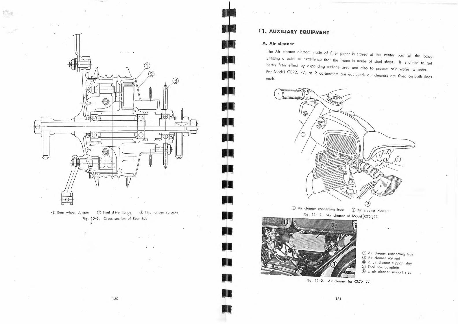
CD Rear whee l damper ® Final drive flan,ge ® Final driven sprocket
Fig . 10- 3. Cross section of Rear hub
-/
130
1 1. AUXILIARY EQUIPMENT
A. Air cleaner
The Air cleaner element made of niter paper is stored at the center part of the body .
utilizing a point of excellence that the frame is made of steel sheet. It is aimed to get
better niter effect by expanding surface area and also to prevent rain water to enter.
For Model CB72, 77, as 2 carbureters are equipped, air cleaners are nxed on both sides each.
CD Air cleaner connecting tube ® Air cleaner el ement
Fig , 11 - 1. 'Air cleaner of Model :C72, ~77,
CD Air cleaner connecting tube ® Air cleaner element
® R. a ir cl eaner support stay @) Tool box complete ® l. air cl eaner support stay
Fig. 1.1 - 2. Air cl eaner for CB 72, 77.
131
B. Muffl~r
Construction of exhaust Muffler. Exhaust pipe conducts exhaust gas from cylinder head
to muffler. Curvetu re of this pipe affects horse power developed exhaust gas conducted
through exhaust pipe is damper inside of muffler by chocking passage and further discipate
sound at the d iffuser pipe to get silencing effect.
CD Diffuser pipe
Fig . 11 - 3. Cross section of Muffler of Model C72, 77.
CD Muffler ® Diffuser pipe
Fig . 11 - 4. Cross seclion of Muffler of Model CB72, 77
MEMO
132
ELECTRIC EQUIPMENT
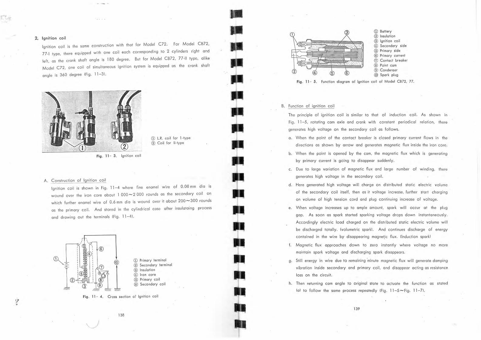
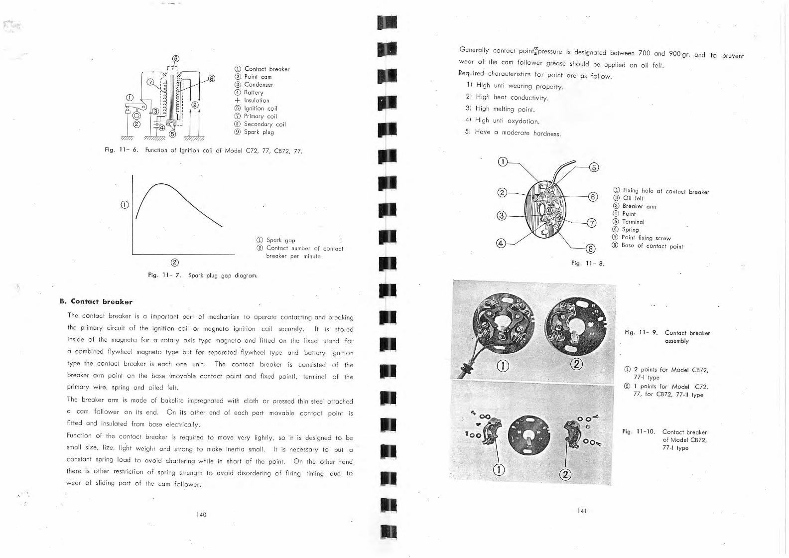
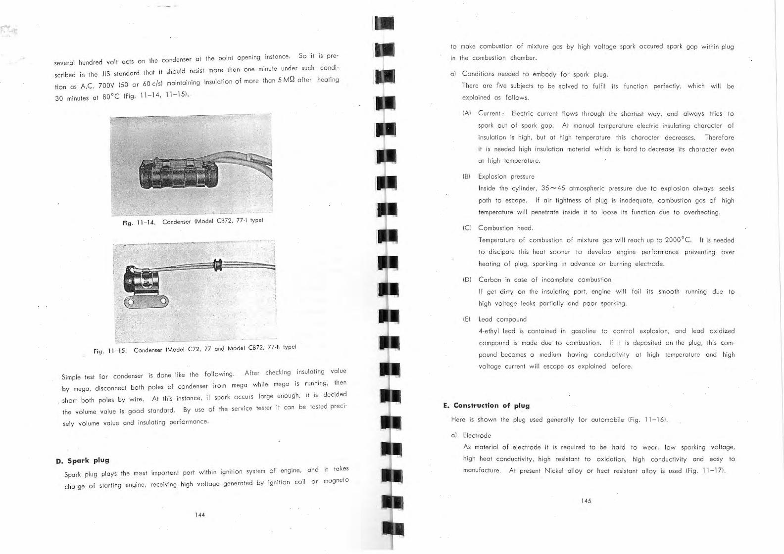
1. Ignition system (Ignition coil, magneto, contact breaker, spark plug)
2. Electric power generator (Rotor type A.C. Generator, DC Dynamo)
3. Rectifie r (Selenium rectifier)
4. Batter y
5. Loading 'illum inat ion light , winker, horn, starter)
El ectric system is impor tant par! for the bicycle alike nervOus system for humankind. Even a
partial damage at engine ignition, light a t night or horn function will affect quite often its
smooth running . We adhere on JI S standard from viewpoin t of manufacturing ' and traffic
transportation vehicle law and security standard for laws & standards.
133
I
CONTENTS
1. SYSTEM
A. Igniti on Circuit ............ ... ....... . ..... ... .....• . . ... • .. . 137
'eeii. ,!ff!!:A~l!ijht BLue (Bk. R )---BLad and Red . CBk, 0 .. · BLack and YelLow (R, i'I )' --Red and White (/ f:. R~::?r~-';.ti::~m an.d Red (8k.~ Y. tube )- --BLack wire covered with yeLLOI~ tube (Bk~8tt. tube)---Blad
' . . '; '.' ,.i~ ~~~~~~; .:: '-.L!ir· Ye llow and Red , ,;:,~ '. •. witt. . covered with blue tube wire cove'rtd with red tllbe (Bk~W.tltbe)---Btack wire i:overd with white tube '-. , ... '-:. "
Y. " ..... .. Yellow Br. --:--- -- Brown P. -- -- •• - Pink
.~.
lGr. -•• -. light Green BI <t R. --- Black <J Red Y. q R. -- - Yellow q Red
.' l Gr: q R.--- light Green 't
W.' R. ·"· White" Red BL:<J W. ~-~ Black q Wh ite
.. . , 1,
" '. Red
>
:')"'/ >';'i - • .Jl1;"'--~ ... .' '.
Va L tage t2 VoLts ,
. ~::)f:
" " .•. ~"'~ ~. _'"~ .:,j ... . ~
-~, .. ~I
. " ~>;~;:i . .; .. :
/ ' . f
2. CHARGING SYSTEM
A. Rotor-type A. C. Generator
The principle of generation of electricity by Rotor-type A.C. Generator is same as that
of the nywheel magnets. Magnetic nux . in the iron core of coil turn its direction as
much ' times as number of magnetic pole for each a turn of the magnetic iron. For each
a turn of the magnetic iron, as magnetic nux in the iron core changes with
magnetic pole number
2
cycles (3 cycles per one turn for 6 poles Generatorl, so there generates A .C. voltage
in the generating coil due to this variation of magnetic nux.
The more magnetic force of magnetic iron, and the earlier rate of change of magnetic
nux in the core Ithe more quick the rotation of magnetic iron, and the more number of
magnetic polesl and also the more number of winding of coil , the large A.C. voltage
is generated IFig. 11 -22, 11-241.
All these conditions couldn't be satisfied from viewpoint of manufacturing, and among
magnetic force of magnetic iron, number of magnetic poles and number of winding of
coil there is such inter relation as to increase one sacrificing other. Due to defects of
Rotor-type A.C. Generator (Flywheel, generating coil of Generatorl, which works with
wrong voltage variation and not equipped with a voltage regu la tor, ' there occur too
much raise or drop of voltage if take the loading a t random not using regular loading.
But recently these defects have been overcome by magnets manufacturers' effort.
On the other hand for magnetic weakening of magnetic iron preventive measures have
been taken in the course of design. (Fig. 11-231
A point of excellence of Rotor-type A.C. Generator due to it simple and strange con
struction is almost no trouble and lack of wear parts. Special feature of using Rotor
type A.c. Generator combined with ignition coil is to make it possible emergency starting
Fig . 11 - 22. Rotor-type A. C. Generator
152
which is impossible to be followed by Rotor-type A.c. Generator. Frequently there
OCcurs perfect discharging carelessly from capacity Battery mounted on motor cycle, due to itssmall capacity.
For the battery ignition system, 't " b I IS Impossi Ie to spark unless replaCing battery or
recharging, but for the Rotor-type A.C. Generator system it is still possible to spark by
kicking even after perfect discharging of b tt d . aery ue to ItS featu re of steep and high
induction voltage of Rotor-type A.c. Generator under l'lght I oad where generated voltage be conducted to ignition coil in D.C. or A.c. as ',t is through celenium rectifier.
Therefore it enables emergency starting by switching of adeq t . . ua e Circuit connection.
CD Coil
® Fixed core (iron COr e and coill ® Rotor (magnetic iron)
o Cronk shaft
Fig . 11 - 23. Construction of Roto r-type
A. C. Generator
A B 20 10
5
q
4
J
2
A; Generator
CD Yellow lusua l usel
® Wh ite Iday and nightl ® Brown (common use)
Fig . 11 - 24. Circuit diagram of Ro to r-type A. C. Generator
11 - 25.-{a) C haracteristics of Rotor-type A.C. Generator (daytime)
153
A 8. 10 10
q CD
15:~ 6
10 5
5
4
J
2
ol~~--~~~~;;~~~--~~--~~--~6~o~oOO--;7~0;OO'--'8~ooo.o,--q~0~O~O--~I~O~OOO o /000 2000 .3000 40 00 SOOO
CD Battery voltage EB o Charging cu rrent ZB
A; Volt B; Amp
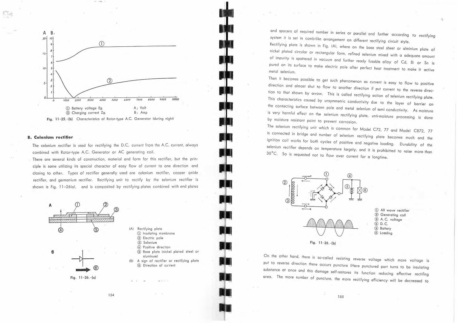
Fig. 11 -25.-(b) Characteristics of Rotor-type A.C. Generator (during night!
B. Celenlum rectifier
·f· th Decurrent from the A.c. current, always The celenium rectiner is used for rec ti ylng e .. .
R A C Gene rator or AC generating cod. combined with otor-type . . f h. fner but the prin-There are several kinds of construction, materia l and form or t IS rec I ,
t directio n and . I h cter of easy flow of current a one C·,ple is some uti li z ing its speclo C oro d
. t·ce copper axi e C generally used are celenlum rec III r, th Types of rectiller closing to a er. .n .
rectifier, and germanium rectifier. un·,t to rectify by the selenium recti ler IS Rectifying
shown is Fig. 11-26101, and is composite d by rectifying plates combined with end pla tes
A
(AI
+® • IBI
Fig . 11 - 26. - (0)
154
Rectifying plate CD Insulating membrane
o Electric pole o Selenium CD Positive direction
® Base pl~te (nickel plated steel o r
a luminuml
A sign of rect ifier or rectifying plate
® Direction of cu:-re nt
and spacers of requ ired number in series Or parallel and further acco rding to rectifying
system it is set in comb-like arrangement on different rectifying circuit style.
Rectifying plate is shown in Fig. IAI, where on the base steel sheet Or alminium plate of
nickel plated circular Or rectangular form, refined selenium mixed with a adequate amo unt
of impurity is spattered in vacuum and further ready fusable alloy of Cd, Bi Or Sn is
pured on its su rface to make electric pole after perfect heat treatment to make it active metal selenium .
Then it becomes possible to get such phenomenon as current is easy to flow to posit ive
direction and almost shut to flow to another direction if put current to the reverse di rec
tion to that shown by arrow. Th is is called rectifying action of selenium rec ti fying plate.
This characteristics caused by unsymmetric conductivity due to the layer of barrier on
the contacting surface between pole and metal selen ium of sem i conductiv ity. As moistu re
. is very harmful effect On the selenium rectifying plate, unti-moisture processing is done
by moisture resistant point to prevent corrosion.
The selenium rectifying unit which is common fo r Model C72, 77 and Model CB72, 77
is connected in bridge and number of selenium rectifying plate becomes much and the
ignition coil works for both cycles of positive and negative loading. Durability of the
selenium rectifier depends on temperature largely; and it is prohibitted to ra ise mare than
30°C. So is requested not to fl ow over current for a longtime.
CD ®
I @
Fig . 11 - 26. - (b)
®
CD All wave rectifier
® Generating co il
@ A. C. voltage @) D. C. ® Battery ® Loading
On the other hand, there is so -ca lled resisting reverse voltage which mare voltage is
put to reverse d irect ion there OCCurs puncture IHere punctured part turns to be insula ting
substance at once and th is damage self-restores its function reducing effective rectifing
area . The mare number of puncture, the more rectifying effiCiency will be decreased to
155
\ .
be overheatedl. Therefore it is necessary to raise total resisting reve rse voltage by
putting required number of plates in series corresponding to A.C. voltage generated by
the generator coil. In Fig. 11-26Ibl, put AC. voltage between terminals P.Q. of the generating coil as IAI ,
181 , ICi == 1 , 2 , 1, it is evident ICi is most suitable for high AC. voltage rectifier as the
reverse voltage per one rectifying plate is smallest. Generally speaking' is selenium recti
fying system for use of automotive AC. generating coil ICi > lSI> IAI is the order to
select corresponding to voltage.
CD Selenium rectifier oss'y
a; Red termina l
b; Brown termina l
c; Volt d; Yellow terminal
Fig . 11 - 26. - (c)
Remarks: Special precaution is necessa ry in using selenium rectifier not to run engine under such condition as no
loading slote \fo r instance unloading stat eof battery during daytime or taking out state yellow of fuseL
as high voltage generated by generating coi l under no load or light load condition a cts to the rever:.e
direction. Th is leads to puncture trouble and wil l damage the selenium reclifier if continued a long
time. On the other hand, there occurs aging change in the selenium rectifier for a long term use increasing
internal resistance in the rectifier plate to decrease output voltage and to increase temperature.
The largest cause of a ging change is temperature raise and at more than 70°C in the rect ifier th is
change occurs rapidly, therefore it is required to select cool position to equip it.
There is such tendency as to increase current to reverse direction if selenium reclifier has not been
used for a long time. In such case, before using raise voltage slowly dyring one hour from lower
voltage [about half of standardl to restore its function.
c. Battery
All the battery for automotive use are lead storage battery and its construction is as
shown in the figure i.e. anode plate group and cathode plate group lone plate more
than anode groupl are put together in turn inserting separator between anode & cathode
plates, and these combined plates are stored in the cell lebonite or stirol model dipped
with electrolysis solution. One unit as shown in the figu re is called an un it cell and
156
generates about 2. 1 Volt l in case of perfect charge, this will be up to 2 5 V chargingl. . during
For Model C72, 77 6 V is used and for Model CS72, 77 12 V is used, connecting each cell of each 3 piece or 6 piece b y connecting rod in series.
b a
c --l-~..I h
0; terminal
b; pate
~ c; dil ute su lpluric acid d; anode plate e; terminal
f; ce lt g ; separator
(B f h; cathode plate
Fig . 11 - 27. Storoge battery
The pole plate is made of lead antimony I attice painted w ith powder of lead oxide in
paste state and dried. For anodic plate, hard lead ox· Ide in dark brown colo r is filled up and for cathode plate gray porous sponge I k i e lead is "lied. There contains expand in b . g su stance to prevent contracting solidification while in use as for separator thO h In cypress s eet Irecently rubber sheet with fine holes are usedl is used d I . . or sythetic plates
, an g,ass mat IS Inserted between d' I ano IC p ate and separator to pre-vent oxidation of separator and dropp'lng b su stance of anodic action.
There OCcurs discharge when connected load between both terminals f b gradually substance of both po',e 0 attery, and
plate changes to Ie d I h a su p ate, accordingly, specific gravity of dilute sulphuric ac id will d ecrease to drop terminal voltage. This rate of
decrease of specific gravity is proportional to amount of discharge . sho . F' I approximately as wn In Ig al. So it wl'll be d ete rmined amount of d' h b h k ISC arge or rema ining amount
y c ec ing variation of spec,'o,c " gravity if known th . 't' I 0 e In l 10 spec illc gravity (sg. at com~ plete charge 1. 260 and sg. at complete discharge 1.1 01 . Specific gravity of dilute sul-
phuric acid varies with change of t t empera ure. If also depend on the kind of battery
but generally about 1,260 is selected with If u converting standard temperature 20°C. p t current on the discharged b tt . h . . a ery In t e directIon reversal to discharging, lead
SUlphate generated on both plates restore their original state, ·'.e. become lead oxide
157
and sponge, lead again, and specinc gravity of dilute sulphuric acid increase gradually
and increase terminal voltage as charging progress.
CD ® ,. t
~ , '" , el' , 0 0
• " ., uo 1.16
1.12 , .. 1.0'
" " : ,~ "
I ' 11
®, "
Ql
@
t-..... t-.....
® ~
"""" ~l'
@
t'--... " ~ ,<1l " 100 80 60 40 20
-@
Fig. 11- 28. Eattery
(a) Discharge characteristics under constant current
CD Voltage ® Specific gravity ® Discharge limit voltage @ Hours of discharging current
® End of discharging ® COmplete charge <1l Total discharge ® Amount of charge
01 Volume and rate of discharge Irate of chargingl
bl
Volume of battery is denned as amount of volume dischargeable down to discharge
end voltage at terminals regulated by JIS from complete charged battery discharging
under constant current. Imean value 1.575 V per each unit celli To express its value
Ampere hour IAhl Idischarging current times discharging hoursl is used.
Volume of battery depends on temperature of discharging current and specinc gravity.
As conditions of volumes test regulated by JIS for use of battery for motor cycle,
speCific gravity of electrolysis solution should be 1,260+0,005 Iconverted to 20 °CJ,
current 1.0 hours rate, and temperature of solution 25 + 2°C. Concerning rate of
discharge, given here the battery completely charged, discharge down to the end
discharge voltage with X ampere within T hours, volume of this battery is expressed
by XT ampere-hours IAhl, and X ampere is called the current of rate of discharge
of T hours.
Therefore battery of 10 hours rate volume II Ah means such capacity as to dis
charge 10 hours down to the end discharge volt and current of 10 hours rate of
discharge is II A. Similarly for charging current, it is expressed 10 hours rate of
charging. To express amount of charging or discharging current, duration of time
in hours down to the end discharging volt .is used.
Initial charging
Battery can be stored after assembly for a fairy long time, if not electrolysis solution
158
be poured in and seal tightly " pouring orince. Therefore when battery not charged
Th is yet is to be used ,initial charging is
solution charging with regular initial
is done after pouring electrolysis
for about 70 hrs. continuously
to attain both pole plates a perfect charging state for the nrst time.
necessary.
charging current
It is required the initial charging should be done perfectly, otherwise this battery will
not display its volume 100% for future use and its life be shorten seriously .
Precaution necessary before starting for use;
Inspection should be done before use of Battery nn'sh d . 't' I h I e Inl 10 C arging as follow,
III Inspect if there is something unusual or not, as damage, happens sometimes during
Especially due to damage on the case there happens leakage of transportation .
solution.
121 Peep inside through pouring port ft t k' a er a Ing cap, or check the level of solution
to be on regular height. If its level is lower, check damage if any on the case.
If no damage, supplemen t dilute s I h' 'd f u p UriC aCI a same spec inc gravity with other.
cell.
131 If time elapsed more than two weeks after the initial charging, it is necessary to
supplement charge to supply amount of self discharged electricity while let alone.
During this supplement charging, it 's d . bl h k I eSlra e to c ec level of solution to adiust
regular height and further measure and ke d f I ep recor a va tage, specinc gravity
Clnd temperature for each cell for future reference.
Fig. 11- 29. Supplement charging of Battery
Precautions wh ile in use ' ,
II Inspect battery
month or after
periodically, once a week for automotive
each I 000-2000 km running.
159
use. At least twice a
21 Special atten tion should be paid on the level of sol~tion. and if short supply
t Ina content of metal. as Ferrousl. If the case
solution, but generally the height
31
distilled wate r or drinking wa er
of battery is transparent there is shown level of If the pole plate
Id be ad lusted about 13 mm over the separator. of solution shou
'd fan on the plate air due to drop of level. there occurs ox, 0'
be exposed in the
lead which decrease volume of battery, and effect the per-
making white sulphuric . . f . h t ng So many troubles
formance of exposed plate to be serious couse a ,nner s or' . therefore it wouldn't be ' exaggeration to soy
are experienced due to this couse,
that is the must po rt of causes to shorten it life.
. . ',nsuff,'c',ent charged d t If used for a long t,me ,n
Keep always in charge sta e.
state trouble called sulphation W',II be accelerated and at lost it invites such dif
flculty as to make it hard to restore
pole plate warps easy to short. On
b I h 'ng Such original substance y usua c arg' .
the other hand , if used with thin solution due
to over discharging separator gets damage.
ment change before the discharge limit. IFig.
Therefore it is requested to supple-
11-29 ~ 11-311.
11 30 Sign of level of solution Fig . - .
11 3 1 Precaution for use Fig . - .
160
For the battery, MBJ4- 12 type IVoltage 12 V, volume 10 hours rate 10 A hl is
applied. Duration of battery is expressed by hou rs from the complete charging
state to the complete discharged state using electricity for each separate loading
while in stationary state. Therefore if the loading overlapped duration will be
shorten so much. This relation could be presumed from the following table .
Kinds of loading on ba ttery Standard M ean consumption of current
duration of ba ttery (approximatel
Head light
Cell moto r
Magnet ic starter switch
Neutra l lamp
Winker lamp
Tail light
Stop light
Speed meter lamp
Ignition
Horn
35/35 W
0.4 kW
3W
10WX2
4W
8W
3W
Stop
Running -
100 P
3 A
10 ~ 50 A
3.5 A
0. 25 A
lA
0.35 A
0.7 A
0.25 A
* 3.5 A
0.8 ~ 1.2 A
1.5 A
* In case of Point closed and switch On
For ins tances, if the head light 35 W is on, consumption
will be about 2 hrs. but if the toil lamp 10.35AI and
Simultaneously total consumption will be 6 .85A. From
duration becomes 35 ~ 40 minutes.
2 hrs
listed On othe r part
" 40 hrs
10 hrs
30 hrs
40 hrs
1.6 hrs
6hrs
is 3A on ly and duration
ignition 13.5AI were used
the figure above shown
While in runn ing, charging is done corresponding to engine revolution, so that riiffer
ence between charging and discharging current will behove charging or discharging.
Charging current >discharging current
->charge battery
Charging current < discharging current
->discharge battery
Especially as large current nows while in use of cell motor, it is required to control
less than 5 seconds for one action. after that tokes rest 1 0 ~ 15 sec to repeat next
action .
There occurs rapid drop of voltage if large current token out from the battery but
it restores the origina l voltage if taken a rest.
Therefore continuous pushing on the Cell Button causes voltage drop preventing re
storation to the effec t of early exhaustion.
161
,
L
" , 8
'"
, ,
8 9 10
-'"
{AI; Discharge current
{HI i Duration
Fig . 11 - 32. Relation between discharge current and duration
for MBJ 4·12 type {12 V. 10 AHI battery.
r-----I I
CD: I I I , L
3' ~ I I
r , I I L
, 6'
3'
6'
- -@ I
-j~
. ilif~~7 l '
Fig. 11 - 33. Charging current circuit diagram.
D. Cell Starter
01 Slarting Circuit
CD Selenium recti~er
® Dynamo ® Battery ill Fuse connector
® Fu se 15 A I ' Red 2' Dark brown 3' Yellow 4' While 5' Black 6' White red spiro I 7' Earth to Frome
The starter switch of push botton style is equipped on the right side of the handle.
Pushing it, the starter magnetic switch is operated to feed current of about lOOA to
the starting motor from the battery for Model C 7 2. 77. and about 60A for Model
CB 72. 77 to rotate the starting motor.
The starting motor is equipped in front of the crank case and the cronk shaft is
rotated by starting chain through the overrunning clutch from the dinamo side.
162
2' .... 1
: ouPCD L J
l'
Fig . 11 - 34. Wiring of Cel l starter
fig. 11 - 35. Starter motor
CD Brush (J) Ball bearing ® Brush spring ® Sprocket shaft ® Field coi l ® Sprocket @ Pole core @ Gear housing ® Terminal @ Planetary gear ® Internal gear @l Center bearing holder
bl Reduction of starter
@
® @ @ @ @
CD Starter switch
® Combination switch ® Starting molor
@ Starting motor cable
® Starter magnetic switch
® Starter battery cable
(J) Battery
] ' Black red spiral
2' Yellow red spiral
York Armature
Cover band Comutator
Comutator end frame
Bearing bush
To gel required torque and revolution to rotate the cronk shaft by reducing revolu· tion of th e motor mechanical reduction is necessary. To complete this in high
163
. d . I'S done by planetary gear and further the secondary weight ,the primary re uctlon
reduction by starting chain.
Primary reduction ratio
Secondary
Total reduction ratio
5,78, 1 Iplanetary gear!
2, 77 ,1 !chainl
1691 , 1
As the starting motor does not run constantly there seldom occurs wear but to
prevent moisture its construction is closed type.
Therefore after each 5,000 -1 0,000 km run the following points should be checked
with care.
CD Check wearing on carbon brush and commutator.
® Eliminaate carbon powder Iblow of! by compressed air!.
® Supply grease in the gear case.
If required by any reason to take out the starting chair, do not disassemble the
slarting sprocket from the motor.
By any chance if the starting sprocket were token out it is necessary to disassemble
Q CD \l ex O~®
fig . 11 - 36.
f ' 11 37 Cel l-motor attached on Engine Ig. - ,
164
CD Inte rnal gear
® Planet gear ® Sprocket shaft @ Sprocket
) <D Pla net gear
® Motor shaft
® Internal gear @ Sprocket shaft
® Sprocket
Fi g. 11 -38 . Reduction mechanism
were taken out it is necessary to disassemble even the planetary gear and the
starting sprocket should be combined before reassemble the starting motor.
If the sprocket were set in, without disassemblying the starting motor by mistake there
happens rolation impossible due to hitting againsts the case by the planetary gear,
(Fig. 11-36 - 11-381
cl Dismounting the Starting Motor
a. Take of! the slarting motor coble from terminal.
b. Loosen each two screws of 6 mm tightening the slarting sprocket cover and
take of! the cover.
c. Loosen two screws of 5 mm on the starting motor side cove r and toke of! the
side cove r.
d. While loosening 4 bolts of 6 mm filled on the cronk case and taking out the
starling motor from the engine case, it wi ll be seperated from engine by re
moving the starting sprocket from the chain. (F ig. 11-391
fig , 11 - 39,
165
E. Maintenance of the Starting Motor.
1. Removal of the carbon brush.
a. Take off the cover band complete of the commutator.
b. Loose 2 bolts fitted on the commutator end frame and take it aut.
c. t th ca rbon brush pressing spring, By taking au e take out the carbon brush
f the field coil and carbon brush. loosening the connecting screw a
A. 3 B.
F· 11 40 Cross section ·of commutator Ig . - .
2. Commutator
C!) Mica piece ® Commutator ICul ® Motor shaft
The commutator is as shown in Fig. IAI while in use copper pant get wear to turn
like IBI.
In such cases its is reguested to adjusts to be IAI.
I h as this adlustment requires highiy technics. It is advisable to rely on specia ist sops
lunder cutting of mical IFig. 11-401
C!) A.c. Generator rotor
® Starting clutch-outer ® 10.2X 11.5 roller
Fig. 11 - 41. Generator srotor and torting clutch
F. Over ru nning clutch
This transmit rotation from the starting motor to the crank shaft, but reversaly from
the crank shaft can not rotate the starting motor.
This construction is quite same with Model C72 . IFig. 11 -4 1 I
166
1. If turns the starting motor
a . When the starting chain is pulled along the direction of arrow as shown in the
picture.
b. By rotating the sprocket, the clutch outer is turned when the roller is joined with
the starting sprocket and the clutch outer moving to the narrower side. Accordingly
the dynamo rotor is turned which is fixed with the clutchouter as one unit.
c . On the rotor is fixed on the crankshaft by a key of 4 mm. rotation of the
clutch outer is transmitted on the crankshaft.
d. The starting clutch roller spring is usefu l for smooth running of roller without any
irregular meshing.
Furthermore a spring cap is used to make smooth motions of the starting clutch
roller spring and the roller.
2. When the engine starts running
a. Rotational spped of the crankshaft becomes faster than that of the sprocket.
b. Transmission from the starting motor is cut, due to centrifugal force on the roller
which presses the spring and moves to the wider space of the clutch outer-
Fig . 11 - 42. Picture showing principle of function of th e overrunning dutch (AI
Fig. 11 - 43. Picture showing principle of function of the overrunning clutch !B)
167
3. Lubri catlon
over running clutch is done Lubrications for the by oil dropped through the hall (AI
through the groove at three parts in the Figure which passes IBI and starys inside of
01'1 real 2035 the inner of 20 mm bush and the lock oil seal 326575 to prevent
burning . I '1 his (AI and IBI by com -afte r disassembly it is necessary to c eon aloe Therefare
pressed air .
Precuation about Maintenance 4.
As L ife of the over running clutch
tion is needed for i ts handling .
depends on the function of roller, special atten-
01 on the roller shou ld grease put
greasel
be used designated one. (Part No. 719111. silicon
This designated
1_40°C ~ 200°Cl,
. high resistant to cold and hot grease have several features, Ie,
other variation.
ff ·· ts due to temperature and least variation for frictions coe IClen
h t by gasoline, and after drying Before putting this grease on, cleanse eac par
over the surface of the roller. up, paint grease thinly all
f 1 bout magnetic force.
b. Be care u a . b t also parts around the clutch should be Not only roller or roller spring, u .
avoided from magnetizinz. '11 f bly affect smouth Any timy resistance WI un avora
running of roller.
No. \
Part name \
Quantity \
N o. \
Part name \
Quantity
1 Starting chain 1 8 Cross hole screw 3
1 1 9 Half moon key lIargel 2 Starting sprocket
3 Roll er 3 10 R-crank shaft 1
4 Clutch outer 1 11 Bush 1
20305 oi l seal 1 12 Starling clutch roller 3 5 spring cup 326275 lock oil sea l 1 13
Starting clutch roller 3 R cro nk bearing housing 1 6 14 spring
7 AC dynamo ro tor 1 15 Z bearing 1
168
F. Starter magnetic · switch
Current to rotate the starting motor will reach about 100 A To reduce resistance big
wire is needed, and als6 the switch to make on or off should be larger size at the con
tacting part. Accordingly it will be difficult to nnd such place as easy to operate
switch feeding current directly on the starting motor.
In such cases, switch utilizing magneto can be equipped at the most convenient place
between the battery and the starting motor and put the switch to operate this magneto
separately to make possible remote control with least current.
1. Principle of function
01 If current nows on the primary side, an electromagnet actuates to attract iron
core resist in g spring force.
bl The contact point at the end of the iron core connects the secondary circuit.
IFig. 11-461.
'.
Fig. 11 - 45 . Starter magnetic switch
Fig . 11 - 46 . Construction of starter magnetic switch