Honeywell Specialty Materials Honeywell P.O. Box 430 2768 North US 45 Road Metropolis, IL 62960 April 6, 2011 Attention: Document Control Desk Director, Office of Nuclear Material Safety and Safeguards U.S. Nuclear Regulatory Commission Washington, DC 20555-0001 References: 1) Docket No. 40-3392; License SUB-526 2) Letter from Larry Smith, Plant Manager Honeywell to the NRC, Surface Impoundment Decommissioning Plan, dated December 2, 2010. 3) Letter from Larry Smith, Plant Manager Honeywell to the NRC, Supplemental Information for the Surface Impoundment Decommissioning Plan Application, dated February 25, 2011. 4) Letter from the NRC to Larry Smith, Plant Manager Honeywell, Completion of Acceptance Review for Honeywell Metropolis Works' Surface Impoundment Decommissioning Plant (TAC L32759), dated March 17, 2011. Subject: Calcium Diuranate Solubility References for the Surface Impoundment Decommissioning Plan Application In accordance with the previous commitment to provide references for the solubility of calcium diuranate presented in Comment No. 1 e. of the Supplemental Information for the Surface Impoundment Decommissioning Plan Application (Reference 3), Honeywell Metropolis Works hereby submits the attached documents and references. If you or your staff have any questions, require additional information, or wish to discuss this further please contact Mr. Michael Greeno, Regulatory Affairs Manager, at (618) 309-5005. Plant Manager Attachment ~Th~3c~I
Transcript
Honeywell
Specialty MaterialsHoneywellP.O. Box 4302768 North US 45 RoadMetropolis, IL 62960
April 6, 2011
Attention: Document Control DeskDirector, Office of Nuclear Material Safety and SafeguardsU.S. Nuclear Regulatory CommissionWashington, DC 20555-0001
References: 1) Docket No. 40-3392; License SUB-5262) Letter from Larry Smith, Plant Manager Honeywell to the NRC, Surface
Impoundment Decommissioning Plan, dated December 2, 2010.3) Letter from Larry Smith, Plant Manager Honeywell to the NRC, Supplemental
Information for the Surface Impoundment Decommissioning Plan Application,dated February 25, 2011.
4) Letter from the NRC to Larry Smith, Plant Manager Honeywell, Completion ofAcceptance Review for Honeywell Metropolis Works' Surface ImpoundmentDecommissioning Plant (TAC L32759), dated March 17, 2011.
Subject: Calcium Diuranate Solubility References for the Surface ImpoundmentDecommissioning Plan Application
In accordance with the previous commitment to provide references for the solubility of calciumdiuranate presented in Comment No. 1 e. of the Supplemental Information for the SurfaceImpoundment Decommissioning Plan Application (Reference 3), Honeywell Metropolis Works herebysubmits the attached documents and references.
If you or your staff have any questions, require additional information, or wish to discuss this furtherplease contact Mr. Michael Greeno, Regulatory Affairs Manager, at (618) 309-5005.
Plant Manager
Attachment
~Th~3c~I
cc:
Tilda Liu, NMSS Project ManagerMail Stop EBB 2-C40MU.S. Nuclear Regulatory Commission.Washington, DC 20555-0001
Mr. Kevin Mattern, NMSS Project ManagerMail Stop EBB 2-C40MU.S. Nuclear Regulatory CommissionWashington, DC 20555-0001
Mr. Michael GreenoMs. Lidia Litinski
2
Uranium Species and Solubility in the Metropolis Works Ponds
There are numerous solid compounds known for the alkali and alkaline earth metals anduranium oxide. Most prominent are those comprising the parent hexavalent U di-anion•2•+- 2+. C 2species, U2072-, complexed with Na+, Ký, Mg , and Ca2 0 to form salts. These arerepresented by the general formula, MxU 2O7 , where M= the alkali or alkaline metals andx has a value of 1 or 2 depending on the valency of the metal cation such that x=2 for thealkali and x=I for the alkaline metals.
During processing at the Metropolis Works, residual U, in the form of U(VI), can becomehydrolyzed into the UO2
2÷ species. Subsequent reaction with alkali or alkaline earthmetals will convert this uranyl species into the corresponding metal-diuranate compound.
For example, if the U022+ cation comes into contact with Ca(OH) 2, the formation ofCaU20 7 is anticipated to be quantitative. The typical reaction sequence is illustrated ineq. 1.
Earlier investigations by Ditte1'2 recognized that calcium, as well as other alkalinemetals, had the capability to form insoluble salts when reacted with residual uranylspecies. Similar work by Jakes et al.3 confirmed these findings and also addedmodifications to the original synthesis Jakes et al.3 demonstrated that a number of solublecalcium salts could serve as a source for calcium to precipitate the uranium species ascalcium diuranate. While these works and those of Meyer et al. as published in "GmelinsHandbook of Inorganic Chemistry" 4 substantiated the qualitative observation that thealkaline metal salts were insoluble in water, it was the report published in "Technology ofUranium" by editor Galkin5 that began to quantify the exact values of the solubility(actually the insolubility) of these salts. He reports that the solubility values for the alkalimetal salts are < 0.5 ppm, which means the U values would be even lower.
The more recent work of Simon et al.6'7 quantified the solubility values for the alkalinesalt, calcium diuranate. Using a reactive barrier as an advanced method for groundwaterremediation, the researchers demonstrated that the solubility of the uranium species,when treated with Ca(OH)2, was < 2 ppm in laboratory tests. These results proved to beso promising that the researchers conducted a large scale field test on the order of 25 x
27.5 mE. The objective of this experiment was to demonstrate that a reactive barrier oflime, Ca(OH) 2, would work under realistic field conditions. The results of the experimentconfirmed that Ca(OH) 2 is effective for attenuating the quantity of soluble uranium salt.Throughout the course of the test, the U values were under 1 ppm. Based on the graphshown, the values appear to be approximately 0.7 ppm.
This provides useful insight at the Metropolis Works given the expected speciation in theponds. From numerous samples that have been taken, it has been established that thereexists an excess of lime in the ponds (see table below).
Normalized Data - AS IS OR WET BASIS%% % Excess Lime % %
Sample Calcium Calcium as LimeFluoride Sulfate as Ca(OH)2 Potassium Moisture
Under these conditions, the soluble uranium species would react with the abundantCa(OH) 2 to immediately form calcium diuranate, CaU20 7. The low solubility of thediuranate would serve to drive the equilibrium to the right as depicted in Eq. 1. From thecurrent analysis of the pond samples, there is nothing to suggest the uranium speciesformed by the addition of any dissolved uranium would be anything other than calciumdiuranate. Addition of a stabilizing agent, such as cement, would further serve toimmobilize the uranium and it would be expected to result in even lower values forpotential leaching of uranium from the ponds.
Prepared by: David Nalewajek, PhDHoneywell R&DBuffalo, New York
REFERENCES
1) Ditte, A., Hebd, C. Seances Acad. Sci. (1884) pages 988-991.
2) Ditte, A. Ann. Chim. Phys., (1884), pages 338-358.
7) Simon, F., Meggyes, T., McDonald,C, Tunnermeir, D., "In-situ reactive barriers versuspump-and-treat methods for groundwater remediation", Report on the Workshop held atthe Federal Institute for Materials Research and Testing (BAM), Berlin, (2001), October18-19.
REFERENCE1
TO: Dave NalewajekDate: 03/16/11 13:22:07FROM: Thomas JongelingSubject: One More Reference Article
Tom,
One last reference:
Die Uranate einiger Metaiie und die Oxydation des Urandioxides. I. Die Calcium•w-anateZeitschrift ftr anorganische und allgemeine ChemieVolume 347, Issue 3-4, pages 218-222, Oktober 1966
, .P2.. Ditte, A., C. R. Hebd. Seances Acad. SCi., CODEN: COREAF, 95, <1882>, 990 - 9903. Ditte. A., Ann. Chim. Phys., CODEN: ACPHAA, 1, <1884>, 353 - 353
ThankDave NalewajekHoneywell20 Peabody StBuffalo, NY 14210
Page 1 of 5
REFERENCE1
( 988 )' On peut verifier, en effet, que, queule que soit la fonction F, les cro-
chets form6s par les cinq quantitls H, a, 3, 7, C, pris deux ' deux, sont
identiquement nuls.)) II en r~sulte que l'intLgration de 1'6quation proposee, qui est A six
variables independantes, pent toujours &tre rameenee A celle d'une 6quation
A deux variables.)) Si la fonction F reste quelconque, on ne pent pas, dans l'Ftat actuel
de l'analyse, aller au delh; mais, si elle ne contient les deux quantitIs
P2 + q 2 -- r 2 et p2 + q• + r, que par leur somme, ce qui arrivera, dansle problme de MWcanique propose, toutes les fois que les masses des deux
particules pond6rables sont 6gales (m = inz), quelles que soient d'ailleursleurs charges dlectriques e et e,, alors on pett achever l'integration.
En effet, aux 6quations ci-dessus j'adjoins la suivante:
(4) [ p pj) - + (q -- q4)2 + (" -- _r1,1422]D2
- [(x-x,)(p-p,)+(.r-y,)(q -q,) + (*z)r ,2=D= co, st.
) On peut verifier : iO que D est une int~grale de ]a proposee, c'est-h-direque, quelle que soit la fonction F, on a, dans P'hypoth~se qui vient d'6t'refaite, (H, D) = o, et clue, de plus, D est en involution avec les pr6c6dentes
int~grales a, 7, C.,) Si donc on resout le syst~me des six 6quations (i), ('a), (3), (4) par
rapport aux six quantit6s p, q, r, p,, q,I r,, on pourra former la diff~ren-
tielle exacte
dV =0 dx +qdy -rdz4+p, d -t- +qp,, d r, + r, dz4 ,
qu'il suffira d'integrer pour avoir une solution complete de la propos6e,d'oAi P'on d~duira ensuite, par des diff6rentiations, la solution du probI6mede Mcanique propose. )
CHIMIE MI•t.RALE, - Production par voie s6che de quelqtues uranates cristallisds.Note de M. A. DITTE.
u Uronate de soude U2 O3 NaO. - 0° L'oxyde vert d'uranium U3 04,chauff6 avec du sel marin en fusion, dans un creuset de platine dont le fondest port6 ý une temperature notablement plus 6lev6e que les parties moyenneet superieure, est rapidement attaqiid; il se forme bient6t, h la surface Cdu
liquide fonda, le long des parois du creuset, un anneau constitud par des
Page 2 of 5
REFERENCE1
( 989 )cristaux emp'it~s dans du sel marin solidifi6; cet anneau, frait6 par l'eaufroide apr~s qu'il est refroidi, laisse de belles paillettes brillantes, jauneverdattre, in.olubles dans 1'eau, mais facilement solubles dans les'acides6tendus, en donnant des liqueurs jaunes. Ces cristaux ne sont autre choseque de l'uranate de sonde U2 0ONaO.
), Si, apr6s avoir enlev6 l'anneau form6, on recommence ai chauffer lamati~re qui reste dans le creusel, on peut en obtenir tn second, bien moinsvolumineux que le premier, et bientkt la substance qui demeure inattaquieai fond du creuset ne donne plus lieu 'a aucun d6p't de cristaux A la sur-face aussi longtemps qu'on prolonge l'operation. La masse, d6barrassee d isel matin part un lavage, est vert fonc6 et enti~rement cristallisee; elle sedissout partiellement dans les acides chlorhydrique et sulfuarique 6tendtus,en dormant une liqueur verte et un residu noir cristallis6 de protoxyded'uranium; quant h la portion qui se dissout, elle est constitute par descristaux de l'oxyde interm6diaire U0• = U20, 2UO.
) Lorsqu'on chauffe avec du chlorure de sodium 1'oxyde Ut04 =U 20-,UO,celui-ci se d6compose et donne de I'oxyg6ne qui, avec le sel marin et lesesquioxyde d'uranium,forme de i'uranate de soude; du protoxyde d'ura-nium, dont une partie se combine au sesquioxyde pour faire l'oxyde inter-m6diaire U0=0 -- U203, 2UO, tandis que I'autre cristallise; enfin duchlore, qui, h ]a temperature de l'exp6rience, ne peut attaquer ni Jesoxydes ni le platine dit creuset, et qui se dfgage; la r6action peut s'expri-mer de la mani~re suivante:
ii 20 Quand on recommence l'exp~rience prec&Ienteen ajoutant au chlo-rure de sodium un pen de carbonate de soude, les resultats sont analo-gues; on obtient un anneau qui se produit lentement et qui renferme debelles paillettes tr6s brillantes d'uranate de soude, et tin residu form6 d'unm6lange de protoxyde d'uraniumet d'oxyde intermndiaire U 01 cristallis6s.II n'en est plus de m~me si le carbonate et le chlorare alcalin sont ml-lang6s en parties sensibleinent egales; on se trouve alors en pr6sence cl'uo
•milieu alcalin et oxydant, dans lequel apparaissent bient6t des paillettesjaunes, et peu A peni tout se transforme en uranate de soude sans aucunr.sidu. Duns ces conditions, en effet, I'oxyde interm6diaire et le protoxyded'uranium lui-meme sont oxyd6s et transform6s lentement, inais totale.meni, en uranate cristallis6.
,, 30 Quand on chauffe l'oxyde vert clans d(i sel marin put et qu'on
Page 3 of 5
REFERENCE 1
990 )ajoute peu 'a pea du chlorate de soude lt la masse en fusion, de mani~re Aavoir toujours dans le creuset une atmosphere d'oxyg~ne, tout se trans-forme pen. 'a peu en cristaux d'uranate, mais avec une extreme lenteur. Si,an contraire, on chauffe un melange d'oxyde vert et de chlorate de soude,celui-ci fond, sa decomposition commence: puis tout A coup il y a d6fla-gration, degagement de lumi~re et transformation presque instantan6e detout l'oxyde d'uranium en uranate jaune non cristallis6; l'addition decarbonate de soude 'a ]a masse rend V'action moins vive, tout en donnant lememe produit. II suffit alors de refondre le produit de l'operation avec dissel maria dans les conditions indiqu~es plus haut: I'uranate cristallise et sereunit tout entier h la surface en un anneau qui, trait6 par l'eau, laisse lesel sous la forme de beaux cristaux jaune d'or.
. Ces trois m6thodes sont g6inirales et permettent d'obtenir l'un quel-conque des uranates alcalins sous ]a forme de belles paillettes jaunes, plusou moins teint6es de vert, remarquables par lear insolubilit6 dans l'eau etlear infusibilit6 au rouge blanc. II est h. remarquer que ruranate de sondese forme bien plus facilement que celui de potasse; car, si l'on chauffe del'oxyde vert d'uranium avec tn m6lange ' 6quivalents 6gaux de chloruresde potassium et de sodium, les cristaux qui se d6posent dans I'anneau sontde i'uranate de soude h pen pres pur. Cela tient h ce que le sel matin, en seformant, d6gage moins de chaleur que le chlorure de potassium, ce qui lerend plus facile 4 d6composer. On a pu faire cristalliser ainsi : 'uranate depotasse, U12 0, K.O; l'uranate de rubidium, U2•03, R 60; i'uranate de lithine,U2 03, Li O; et l'uranate de rnagndsie, U2 0.1, Mg O.
) Uranates de chaux. - Quand on chauffe de 1'oxyde vert d'uranium avecdu chlorure de calcium pur, bien exempt de chaux, it se forme un anneaude cristaux et de chlorure sodifi6 avec une lenteur extreme, et finalementon obtient an. fond du creuset, comme avec le sel manin, un melange cris-tallis6 d'oxyde interme'diaire U'O' et de protoxyde d'uraniumn cristallis6.Les cristaux de l'anneau, isoles par des lavages A Y'eau, pr~sentent la for-mule U2 0-, CaO.
D L'oxyde vert, chauff6 avec du chlorate de chaux, se transforme tota-lement en un uranate non cristallise qui, traitO par le sel matin ou lechlorure de calcium en fusion, ne s'y rassemble en anneau qu'avec uneexcessive lenteur. On obtient, cependant, par ce proc~d6, des paillettescristallis~es jaune verdatre, mais elles renferment moins de chaux que lesprec6dentes, et leur composition conduit 4 leur attribuer ]a formule2 "•2 ,06 aO,
Page 4 of 5
REFERENCE 1
(991 )On obtient identiquement de ]a mgme mani~re et sous la forme de
cristaux les uranates de strontiane, U-2Q0, Sr Oet 2U 2 0., SrO, et les urana2esde baryte, U2 01, BaO et 2U 2 03, BaO; tandis qae ceux de strontiane cris-tallisent plus lentement encore que ceux de chaux, les uranates de barytese produisent, au contraire, dans les memes conditions avec une granderapidit6.
,, Ces uranates se pr6sentent sous la forme de paillettes jaune verdattre;ils sont insolubles dans I'eau, solubles dans les acides 6tendus et tr6sr6fractaires. Maintenus longtemps au rouge blanc, leur couleur devientplus foncee, en meme temps qu'ils deviennent plus difficilemnent solublesdans les acides dilu's. •
CHIMIE ORGANIQUE. - Sur le second anhydride de la mannite.INote de M. An. FAucoz,'iER, pre'sent6e par M. Wurtz.
ac Lorsqu'on sonmet ]a mannite 'a ia distillation s~che dans le vide, onrecueille un liquide jaune brun, m61ang6 de mati~res empyreumatiques.Ce liquide, filtr6 sur un filtre mouill6 et rectifi6 au thermom~tre, passe h ladistillation depuis 6o0, A la pression ordinaire, jusqu'& .2000 et au delhdans le vide. Les portions recueillies t 16o.igoo, sous une pression de0 m o3, sonten partie form~es da second anhydride mannitique CIHe°OA.
) R6cemment distill6, le corps se pr6sente sous la forme d'un sirop in-colore, qui, lorsqu'il est parfaitement pur, se prend en cristaux volumi-neux, fusibles 'a 870, et paraissant appartenir au syst~me clinorhombique;it bout sans alt6ration hL 1760, sous olw,o3, et avec d6composition partielle i274V, a la pression ordinaire; it est tr~s soluble dans l'eau et dans I'alcool,insoluble dans I'6ther; ii pr6sente ý un haut degr6 la propri6t6 de resteren surfusion et de former des solutions sursatur'es.
c ........... 49,09 49,12 49,31H ......... 1.. 7fo 6,95 6,84
Page 5 of 5
REFERENCE 2
A. DITTE.
IlIIGIIEiICIIIES SUIR LUIANIUMI;
PAL AlI. ALFaRD DITTE.
1. - AC-TIO DE L'ACIDE HLUOIinYDIiIQtJE SUR L'0OXYDE
DlUIIANIIUlh.
1. Lorsqu'on traite l'oxyde vert d'uranium U'O+ .par
de l'acide fluorhydrique concentr6, l'attaque, len Le A froid,
devient rapide d6s quo la tempdrature atteint 5o°. Quand
l'aeide eat en exc6s, tout P'oxyde se dissout et unfaible ddga-
gement gazeix se manifeste en donnant uaissauce h une
mousse verte peu abondante; P'oxyde se transforme euti&-
rernent, d'autant mieux qu'il a 6Wt moes calcin6, et l'on
obtient, d'une part une liqueur jaune verdfitre, de I'antre
une poudro verte extramement fine cc lhg~re, qui par le
repos se rassemble an fond du vase. On peut sdparer ceLte
derni6re par filtration, reais il est prdf6rable auparavant
d'6vaporer la liqueur i sec pour chasser l'excs * d'acide
fluo,.h'ydrique, on reprend par l'eau bouillante, qui dissout
le sel jaunt! en laissant on rdsidu vert tr~s difli cile i laver,
car il se colle A la surface du filre el en bouche les pores
compItement. La liqueur jaune lentement 6vaporge aban-
donn~e de petits cristaux qui, sdchis A 12o0, prdsel]tent ]a
coMpositiOn suivante :
uiLCIIiCHES SUR L'UnAIMusi. 339
Lement l'uraniun, on la souinet A ine cristallisation nou-
velle.2. Le fluorhydrate de sesquifluorure d'uranium, chauflfi
dans un creuser fermd, fond d'abord en une liqtueurjaune,puis laisse d~gager de l'acide fluorhydrique, et il se sublimne
parfois des traces d'une mati&re blanche doet nous par-
lerons plus loin. Si on laisse Pair pdn4trer dans le creuset,
son oxyg6ne ddcompose le fluorure avec hequel il se trouvu
en contact, de sorte que la d~composidion, trs lente daris
un creuset fermd, s'effectue rapidement, au contrair,, si la
calcination so fait & lair libre. A un moment quelconquo
de l'opdration, le creuset renferine do pro[oxyde d'uranium
so0s la forme de crisLaux noirs, brillants, et di floorure
non ddcomposdi ce dernier eat tr6s soluble dans I'Peat qui
lVenlive avec facilit6 i il a perdu tout son excbs d'acide fluor-
hydrique et prdsente la formule U'FI' da sesquifluorure.
II contoent, en etfet:
Tramv&Uranium.... 67,7Fluor ....... 32,a8
1OOO0
Calculil.
67,78
100,00 0
Uranlium.. •Fluor .....Hydrogkne.
Trouid.
6o ,938,4oo ,62
100,00
Calculi,,
6o0,938,570,52
100,00
qul correspond A Ia formula U2FIP,HFI.La co uposi 6t011 delIa ma Lire no chat)ge pas, lorsque, apr~s
l'avoir traitde par I'eau. oxyg~nde pour peroxyder coimpl6-
I
Page
Uraninm .....Fluor ......Oayg•ue .....
3. La substance verte resLde Sur le filtre et insolubledans l'eau est aussi fort peu soluble dans I'acide fluorhy-drique ou dans lea acides dtendus, m~me A chaud; ellh sedissoat entibremen L dans un mnlange d'eau regale et d'acidesulfurique dilud et contient:
Trouvd.
77,5412,24
10,22.
100,00
CalculS.
77,4212,26io,32
100,00
niombres qui correspondent i, ]a formule U1O'F1.4. Ces donndes permettent de se rendre compte de cc
1 of 10
REFERENCE 2
U
34o A. DITTY.
qui se passe iorsqu'on trahte 'oxyde vert U'O par l'aeidefluorhydrique. Si Von vegarde l'oxyde vert comine pou-Yaw, dans des conditions conveuables, seditdoubler ean ses-quioxyde et cn protoxyde
2(U304)= • 1U'O-4- UO2,
le sesquioxyde au contacL de l'acide fluorbydrique donniede Y'eau et do sesquitluorure qui se combine avec une partiede l'acide eai exc&s; quant an protoxyde, il se comporte Aitencore comwne un corps simple, so conibinant an fluor en,nettant en liberti do Phydrog-nequi constitue le faibled&-gagement gazeux constatZ. La rdaction peut alors s'icrire
On pent, vitrifier cette formule ea traitant utu poids de!-termnln d'o~xyde ver.t par de l'acide fluorhLydrique, 6valio-rant it see et sdparant par l'eau le fluorhydrate do fleorure(u fluorure d'uranylej Ies poids de ces deux composds sonIentre eux daus un rapport irks voisin do celni qu'on diduitde ]a formule. Oa ,vouve, par exemple
UV F1', IZ FI ... oifUO F0, ........ 58 dont le rapport est 2,4.23.
Le rapport Ltidorique serail a,54 2; cette faible diffirences'explique par la tris grande difficulht que Von oproave itlaver )a fluorare U-'O'gl etL ja scparer des traces du selsoluble qu'iJ peut retenir.
Le sel U2O'FI pent s'obten)ir 6galement ea traitant, parI'acide fluorlsydriquc concentrd et chaud, le protoxyded'uranium prove,;ant do lh rvdurtion deloxyde vert parl'hydrog6ne, au rouge ; toutefois I'attaque est extrnmenien ,lente, et l'on n'obtient qu'une faible quantitti do fluoruepar cc procdd6.
Ce fluhorure doit ktre regardd comme un fluorure d'ura-,,yle ( U20 ) Fl, analogue au ehiowrure (U'O')CI, et non pas
At• 3 ,.
IECFIEIIC13ES SUNs L UIUAJUM. .34coniome un oxyfluorare ditriv6 de U10O on do U'JFP. 11 sodistingue, en effet, du sesquifluorure et de son-dirivi, quenois dirirons plus loin, en ee qu'il est vert, insoluble dansI'eau, difficilement soluble dens -'acide chlorhydriquebouillant, en dornant une liqueur verte da,,s laquelle I'am-moniaque produitun prdcipit6 brun verdAtre deprotoxydehydratd; les premiers, au contraire, sont jauces, solublesdans Peau, et dounent une solution dens laquelle l'ammo-niaque produit un prdcipitý jauue d'uranate d'animo-niaque.
5. Chauffie dans an creuset fermnt, cetie substance fondan rouge, puis elle 6met des vapeurs tr6s denses qui augmen-tent, quand on porte ]a tempdrature an rouge vif. Ces va-peurs se condensent au rouge sombre sur les parois ducreuset en ine neige trs ldgire, fornaie do belles aiguillesblanc jaunhtre et transparei!tes; bient6t le sublim6 cessede so produire, et ii reste au fond du creuset des cristauxnoirs, brillants, de protoxyde d'uranium.
La matiire volatile est extrumement soluble danas 'eatt;' elle donne une solution jaune et contie,,t
Trouvd. C000l, .
Uranium..... 72,24 72,28Fluor _.... 2.85 22.80
Oxygine ..... 4,91100,00
4,83100,00
IElle a done pour formule U'OFI'.Le fluorure d'uranyle souanis i l'influence de ]a ebaleur
se didouble done eta oxyfluorure volatil U'OFJ qui se au-blhsne, et ea sesquioxyde d'uraniu;ni mais celui-ci, ri'sinstable, perd iminddiateickc une partie de son oxyg~neeLse transformnedans cette atniosplhce fluorhe en protoxydecristallisg
2 (U'O`FI = U0FI -O-4 UlO,
, 01=0W....-
Page 2 of 10
REFERENCE 2
342 IXECUPRICflCS sum' LtJUiUIIUMi.343
A. TITTV..
Le s nombres qui suivCut vdrifient cette manrde e dvoir.
UCO0FI CMpIoyi ............. 240
Trouv&. Caletild.
UO crislallisA form... i. 2 III
U2'O F0 recueii ..... 13o 13o
Le sesquioxyde U20' eat ddcomposd sons Vaction de la
chaleur, non pas en protoxyde et 0xyg~ne, mais en don-
itant de l'oxyde vert U304, La prdsence de vapeurs fluordes
change le mode de ddcomposition et.permet la formation
du protoxyde. Ainsi, quand on ajoute A de l'oxyde vert
U1 QO quelques gouttes d'acide fluorhydrique et quel'on cal-
cine, cet oxydiL3 perd un quart de son oxygene et se trans-
forme en protoxyde noir cristallisd. Ainsi, par exemple,
og', 149 d'oxyde U'O'c alcine4s avec qnelques gou tes d'acide
fluorhydrique laissent oG&,t44 de protoxyde cristallisd.
C'est la quautitd thdorique, et c'est 6videmment MA le
moyen le plus simple pour o0benir le protoxyde d'ura-nium.
L'oxyfluorure UWOF' est une neige blanc jaunftre,
tr&s soluble ilans l'eau; il fond an rouge et so volatilise
presque imunediatczneze en donnant d'4paisses fumdes qui
se coudensen t surles parties relativement froides du creuset.
L'oxyg~ne de l'ar ddcomnpose immddiatement )a vapeur
d'oxyfluorure et transforme la neige blanche en une suie
noire complitenent itisoluble de protoxyde. Les aiguilles
d'oxyfluorure brusquement chaulrdes A l'air deviennent
noiros et se trasisforment, sans perdre leur forme, en prot-
oxyde cristallisi.Le fluorure d'uranyle U'O'FI, chautTd an rouge dans
P'hydrogine, perd une grande partie de son fluor et doune
de I'acide fluorhydrique. Finalement, i1 ne reste que du
protoxyde cristallis6l; ,nais, taut que la ddeomposition de-
nicure incomplete, on obtient, en chauffant fortement la
mati6re, un sublitnui d'oxyfluorure, UWOFI', cristallisd.
U. - AcuoPF DEs iLUoeURES ALCAL1IS SUu ,'OXYDZ
- valiT v'uiu~vC1UM.
6. Quand, aulieu do faire agir Vaci defluorbyd,'ique sur
l'oxyde vert d'uraniuum, on le trai te par du fluorure neutre
de potassium fondu, en ajoutant Un peu do carbonate de
potasse pour assurer )a neutralite du fluoruro, l'oxyde se
change an bout de quelques instants en belles paillettes
jaunes, transpareutes, insolubles dans r'eau chaude on
froide, et faciles A s6parer par consiquent du fluorure de
potassium. Ces cristaux affecteut )a forme de tables minces,
hexagonales rdguli&res ; elles ne sont pas altdrdes par une
calcination an rouge, et elles Ae dissolvent avec facilith dasn
les acides iteadus. 17,n chaufant ces paillettes avec un excAs
de chlorhydrate d'ammoniaque diStilldM, dans un tube port6
au rouge et travers4 par un courant Whydrogsne, l'uranium
passe A N'dtatde protoxyde cristallisd6, lapotasse i 1'dtat de
chlorure de potassium, et l'on trouve pour la compositlondes cristaux :
it'
IIProtoxyde d'uranium...
• iuorurede potassium:.Fluor ....... : .......
Trouvd.
5o,13 50,27
4-,74 4-,777,20 6,95
100,00 100,00
5o,1742,80
100,00
Ces nombres, vgrifids par des dosages de l'uranium &
r'Atat do phlospliate d'urale, et de fluor sous la forme de
fluorure de calcium, concordent avec la formule
USOIFI, KFl.
Le mrme'sel se produit quand on fraite l'oxyde vero par
du fluorure aoide de potassium fondu : tout so dissout
d'abord, mais l'addition A la masse fondue do carbonate
do potasse qui Ia rend alcaline dutermine la prdcipitation
Page 3 of 10
REFERENCE 2
346 A. DITTE.
Flhorure de rubidium..Ur.ir uiu n ..... .......Oxyg6ne .............Fluor ...............
Troqvy.
57,5533,oo4,255,2.0
100,00
Calould.
57,5432,874,38
100"00
correspond Ala fbrrnule U'0F1, 2RbFI.En opdrant avec le fluorure acids de rubidium, l'oxyde
Vert d'uranium s'y dissout, et ]a masse reprise par I'eaudo01e par dvaporazioo des cristaux jaunes, en tout sem-blAbeas au coinpoa4 analogue formi par to fluorure de po-tassiumn ; lour formule eat
U1 0 F1' 2 Rb Fl, 6H0.
10. L'oxyde d'uranium traitdpar ua mdlange do flnoruredeolthium,.avec une petite quant h4 de carbonate de hidune,dounedes paillettes jaunes insolubles dans l'eau, mais trbsdifficilesA purifier, h cause de la faible solubilit6 du carbo-nate et du lluorure de lithium; elks sont, du reste, solublhsdanas ls asides dtendus, inaltdrables par la chaleur, etcontiounnl t:
A
IIlECUSuaCHES SUR L'URAlI'TJM.
III. -- AcroVTlO DES CHLOflUuIta ALC&LIDIS SUR L'OXYDE
VElT 0 URAVItUM,.
En remplagant, dans les expdriences qui pric~dent, lesfluorures alcalins par des clalorurcs, les rdsultats.aont toutdiffdreonts, et Von obtient des sets dana lesquels lo rbled'acide est joud par du sesquioxyde d'uranium.
12. Uranate do soude.. - i.0 L'oxyde vert d'uraniuznUWO'., chauffd avec du sel marin fondu dans uuicreuset deplatine dont I fond est portd A une emrperature notable-ment supdrieure A celle des parties mnoyenne oi Supedrieure,donne trts rapidement naisaance, auprks de Ia surface libredu liquide et l.e long des parois du creuset, A un auneausolide forild de cristaux empftds dans du set maria soli-difid ('). Cot an,,eaua tant enlevd, ii s'en forme un secondbien moins volumnineux, mais bient6t la substance inat-taqude, qui rests an fond du creuset, ne donne plus lieu &aucun ddp6t de criStaux A Ia surface, m•ime aprks unefusion prolongde. Pendatit que les cristaux se produisent,on voit de petites gerbes lumineuses se ddgager de la massed'oxyde placde au fond du ereuset et se propager dans lechlorure en fusion, A nesutl'e que l'anneau se forane A sasurface.
Cot anneau, traitd par Peau froido, lui abandonne dusol marin et laisse do belles paillettes brillantes, jaune.verdAtre, insolubles dans Feau, mais se dissolvant bien Afroid on A cbaud dane les acides 6tendus, en donnant desliqueursjaunes. ItIen est ainsi avec I'acide sulfurique enparticulier, etia dissolution additionade d'alcool donne unprdcipitd blanc de sulfate de soude insoluble dans ce li-quido, pendant quo du sulfate d'urane reste en dissolution.
C') C'est le mdme proedid qui m'a petmis de prdparor des borates r'is-tallieds par voie sache. Voer Compee: readsi daes stmice: de J•'caddue
des Sciences, t. LXXVII, p. 78 3
-8D2; z873.
347
Protoxyde d'uranium...Fluorure de lithium..Fluor ............
TrOuvy.
65,55'25,19
9,26100 000
Calculi.
65,70
25,12
9,18100,00
quantitas qui correspondent A la formule
* U' 02 Fi, 2 Li Fi.
11. Enfin le fluorure de thallium se comporte encorede mdme ; il donne do belles paillettes cristallines, mais]'opdratiou. est plus difficile, eo raison de la facile volatili-
sation de cc fluorure.
.-- ,:. . ..
4
1'I
Page 4 of 10
REFERENCE 2
348 A. "IrTTS.
Les crisatanx soiiL do 'l.'urenate, do soude pnir, dont ]a for-
nitile 0iO~iNaO 05 46idlUito des nonibrvs suivints.s
Le chlorure de sodium fondu, qui reste dans le creuset,contient au fond. uiie couche Presque ohire; celle-ci,traitdo par l'eat/ qni Ia dsbarrasse du chlorure, laissedd-poser In substa•ce qni nie donfie plus de cistaux se rdu-
nissaut en annean. C'est une matidre vert foncr, tr~s net-
tement cristallisee et partiellement soluble dans les acides
sulfa rique et'chlorhydique ditendus5 elie donne urie it
qut, ur verte, A fr'oid comme a chaud, dans les acides autres
que l'acidc az•tique dtendu1 et un rtsidu forrti de prot-
oxyde d'uranium UO pur. Quant i la liqueur verte, elle
donne avic l'ammouiaque un pricipilS brun noirltre,tout i fait.dirffirent de celui qUi se forme dans les dissolu-
tiols de sesquioxyde et qui est un hydrate de l'oxyde in-terin6ddiaire U4 0'S
Les proportions respectives d'uraiiate de soude, ae prot-
oxyde d'uran*ium OL c'oxyde TJ-Q0' qul se forment varient
A chaque opgration; voicd, en effet, cc qui se passel'oxyde U30 4 1 0•0•, UO se dicompose en donnant do
l'oxyg6Ae qul, avec le sel main et le sesquioxyde d'ura-Uiiul, formie d l'uranate de soude, du protoxyde d'ura-
nimn dout unri partie so combine au sesquioxyde pour
Or i'oxyde vert U300, qUli provien L do ]a calcination d"nitrate d'urane, est toujours plus ou flioils dd-conuposu
pendant cette calcinatioli et est, e,, rdalit. Un midlange Va-
riable de U3 04 Lt do U"1Or ; cc dernier se borne a cristal-liser; le premier donne lieu i ]a r6actio., cc qui explique
qtIon puisse trouver des proportions variables des trois
prodfiits qui prenueut ntaissauce. On pent admettre encore
que I'oxyde U, O existait tout forliil cit r'a fait que cris-
talliser duns le chlorure; on a alors la formule ci-dessnuspourexprimer la rtacdot :
2 (23)OUO)+_jNaCI -- U;O., aO + 4 UO 4-f-CI.
V Si l'Oi, cof•lLClOencel• l'opnration prucdoddute, on ajuu-taut au sel Lnarin unr petite quantite de carbonate de
soude, il se forine tr•s lentemeitL uu, anneau, renferiunt
de belles paillettes jaulnes tr•s brillantes, que l'on retrouve
aussi disstmindes dans toute la masse refroidit,; ii reste
encore au foudt du. creuset, uln nlauge do protoxyde d'ura-
MUM criatallisd, insoluble dans I'acide chlorhydriquc6tendu, et de UO5 c,,isiallisA qui se dissont daes ccrdacdf.
Mais, si Von mnlange le sol marin et lc carbonate de
soude envirbn h parties dgales, on se tronve eu pruseacad'uu milieu alcalin CL oxydant; IH se formhe rapitcrmout i4
la surface du liquide, puts h son ititrieur, do bellos pail-
leLtes jaunes, et, pea h peu, Mais trws lenuineut, tout
P'oxyade d'nxranium so transformo en uranale do soude saus
aucua rdaidu. Dans cc tatflange,, le protoxyde d'uraniuu,lui-m•me, obtenu par l'action de Yhydrog~Ae au rouge
sur 1'o.yde v-rt, se transforine, letlAment ina;s totale srieut,
ell uranate de soude cristallisd. La masse tvaitdc par Veau
4
IPage 5 of 10
REFERENCE 2
35o A. DITT".
laisse uae liqueur colorde en ,ji-une, ce qui n'est pas sur-prenant, 'uranate de soude dta'nt soluble dans l]s car-bonates alcalius. Donc, an presence d'un excbs de car-bonate de soude, tous lea oxydes d'uranium se changenten uranate de soude cristallis6.
30 Quand on chauffe Poxyde Yert dens du sel marin. pur et qu'on ajoute, de temps en temps, un peu de chlo-
rate de soude ax bain fondu, de maniire A avoir toujours* ne amosphlxre doxygkue, tout se transforme pea A pen eu
uranate, mais avee tue exkr6nwe eeWuOU1. Si, au contraire,on chaull l'oxyde yern avec du chlorate de soude, celui-.eifond, sa decompose, puis tout i coup il y a d~flagration,degag,,mcat de lumiire at transformation 'ubhte de toutl'oxyde d'uranium eu urauate.jaune et non cristallin, quelque soit F'oxyde employd. L'addhion de carbonate desoude au chlorat: rend laction moins vive, mais on ob-Ident encore le mrme produit non cristallisd. Celui-ci,chauffd ensuit" daus le chloure de sodium en fusion, ycristallise peu A peu et so rdunit Lout entier A la surfacean un anwcau qui, traitd par P'eau, laisse luranate sous laforine dobcaux cristauxjaune d'or.
L'additiou au sol fondu d'une substance non oxydante,Celle quo l sullato de soude, ne modifie en rnen les premiers.rdsultats: on obtient ue cartaine quantiti d'uranate deSO~tde et un rtisidu cristallis6, formai ' un mnlauge d'oxydeU4 Or et de protoxyde d'uraniun,. Ce dornier, cbauffd seuldans le sol en fusion, ne s'alt~re pas, il ne se forme pas trace
do paillectes d'urauatoede soude, mAmo quand on prolonge]'operatiorl.
13. tlranate de potasse. - Tout ce qui vient d'ktedit de I'uranate de soude est applicable A celuxi do po-tasse.
i' Lorsqn'on cf iauff l'oxyde verL avec di chlorure depotassium en fusion, il so forme, iuais avec une tr6sgrande lerteur, uni annecau duquel l'eau extrait de beaux
-d
I
J
BF.CHEliCHES SiTA LiIIIAmumO. 551
1
I¶
Cristaux jaune verdltre, solubles dans los acides 4ten)duset qui contiennent :
Troavd.
TJ2O' ............. .75,3"KO..............2-,68
e00100
Galculd.
i5 ,3926,61
100, 00
C'est done de l'uravate de polasse U203KO; on les
obtient Irbs purs, en mainteuant une atmosphkre d'oxy-g6ne dans le creuset, et cela en projetant sur [e hain fondude petites quantit& de chlorate de potasse. La masse dechlorure de potassium eat faiblement jaune, ce qui. n'a- paslieu dana le cas du sel marin; aasgi sa dissolution dansl'eau donne-t-elie uie liqueur jaune, dana ]aqueolo l'am-moniaque produit tin prkcipitA jaune d'uranaie &'ammo-niaque, d'aillcurs fort pen abondant. L'uranate de potasseest donc un pea soluble dans le cilorure fourun correspou-dant, ce qui n'a pas lieu, pour x'uranatc de soude.
20 Ea faisant dtflagrer un oxyde qnelcouque d'uraniumnavec du chlorate de potasse pur, .on m6lang6 d'un Oeu decarbonate, on obtient immddiatement l'uranate jaune depotasse non cristallis. Celui-ci, chauff6 soit avec duchlorure do potassium, soiL avec du sol marin, cristalliselentement et forake un annean duquel l'eau extrait debelles paillettes tris brillautes, donti raspect rappelle celnide l'iodure de plumb, sauf la teinte verditre que preseu-tent en g~n6ral lea sels d'urauium. Les oxydes de c inktal,chauff6s avec de ia potasse ean fusion, se transforment •ga-lement on uranate do potasse.
30 La formation de l'uranate de soude est plus facileque cello de Puranate de potasse, car, si l'on chauffe l'oxydevert dana un mwlange A 4quivalents 6gaux de chlorures depotassium et de sodium, lea cristaux jaune verdhtre qulse ddposent en anneau ne contienient guere quo de l'u-ranate de soude. Dans toutes ces opdrations, on observe un
.1
Page 6 of 10
REFERENCE 2
352 A. DITTE.
phiwruene ddjiý signale : de Poxyde qui se I'ouve an fonddu crenset partent constammet cd petites traindes lumni-neuses qul se repandent dana ]a masse eu fusion icc sont
des courants de liquido plus chauds que les parties voi-
sines et qui, ?. mesure qu'ils se refroidissent, laissent dd-poser de petites paillettes brillanLes d'uranate qui vont so
rassanibh.r das l'asieau.Cos uranatos alcalins soet remarquables I ]a Lois par
leoi' iusolbbiliti conpylte daus Peau et par le fait qu'ilssont infiusibles aon rouge blanc.
14. Uranitc de rubidium. - On l'obtient absolunientcommo uplui do potasso, auquel ii ressemble tout h fail. 11
coueionie
RECHIERCHES SURt L'UUAI4IUM. 353
oristaux jaunes tout A fait analogues h ceux qui se sont
produits dans lea mbmes conditions avec la potasse et lasoude; ils contiennefit :
&'oft la formule U' 03 CaO.L'oxyde U30, chauffd avec du chlorate de chaux, se
transforme enti6rement en un uranate cristallin. Ce
dernier, chauffg dans du chlorure de calcium ou dans du
sel maria, ne s'y rassemble en anneau qu'avec one ex-
cessive lenteur, mais il est un pen soluble dans le chlorure
de calcium fondu qui le d6pose en refroidissant, et lamasse traiLte par 'eau lui abandonne des paillettes aris-tallines qui contiennent :
Trouv6.
US O"1 ............. 60,39RbO ............. 39,61
I 10,00 II
ct'o6 la formnle fl-O'RbO.'15.- Utranato de lithi•e. - It se prdpai
prdeedents, en remplaecant le chiorure alcalirue do lithium.. II so pr•sente en helles pailisdes qui repondent l a formule U2 03 LiCel affel :
t20o .............
lO ............
Trouvt.
90,589140
100,O00 I0
Cal culd.
6o,6339,37
0O,00
re, comme lean par du chlo-illettes cristal-). It ronferme,
Caleuld.
9o,56
9,4400,00
uffe de l'oxyde
u pur ot biencnistaux avec
du creusevt un1 7
raitd par 'eaoneau laisse des
Troavd.
0U103 ............ 9.90,94
CaO ............ 9,06100,00
Calculd.
8,87
100,00
"- Cet uranate prdsente done la formnule %U2 Os CaO, i1 eaten paillettes jaune verdAtre, plus foncdes que les prdcd-dentes, soluhble dans los acides Atendus, mais moins faci-loment quo lorsqu'il W'est pas cristallisd iit est excessive-meat r6fractaire; apr&s avoir dt6 longtemps maintenu aurouge blanc, ii est devenu d'uoe couleur plus foncie etplus difficile & dissoudre dans les acides; it feat employer,pour le faire cristalliser, du chlorure de calcium Lienexempt de chaux, car, en enlevant cella-cl avec un acidedtendau, on dissoudrait en m~me temps uue partie de]'uranate.
17. Uranates de strontiane. - L'oxyde vert d'uraniumfondu avec du chlorure de strontium se comporte comma
.dAn. do C•iian. cc dc Phys.. 6 sadrie, t. 1. (Mas 1884.) 23
16. Uira,,aiteeczatux. -- Qand on ehavert d'uranium avee da chlorure de calciunexempt do chaux, il so forme un anieau dou1ic lenteur .Xtrimc, et it reste au fond
ii, lauge cristallisd d'oxydcs UO ct 00'. T
qui dissout ie chlorure do ealhisitm, l'na.t
Page 7 of 10
REFERENCE 2
354 A. DiTTU.
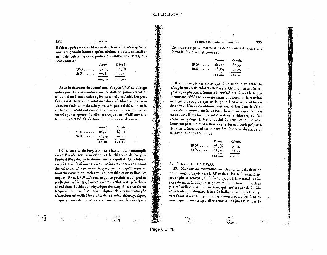
il fait en presence du chlorure decalcium. Cen'est qu'avec
-une tris grande lenteur qu'on obtient un anneau reofer-
mnit de petits cristaux jaunes d'ufanateU 2 0'OSrO, qui
Coutiellnlelit'Touv&. Calculi.
UtO' ...... 72, 59 73,48SrO ....... .27,41 26,52
100,00 100,00
Avec le chlorate de strontiane, i'oxyde U10, se change
eltiirement en une matihre non cristalline, jaune verditre,soluble duns P'acide chlortLydti'que itendu et froid. O,, pent
faire cristalliser cette substance dans le'chlorure de stron-
tium en fusion i mais elle y est tr~s pen soluble, de teile
sorte qu'on u'obtient que des paillettes microscopiques et
en trbs pietite quantiti; elles correspondent d&ailleurs A la
formule 2UIiOSrO, ddduite des nombres ci-dessous:
IIECIIEICHlES SURl L'URILMIUM. 355
Ceturafla~ttrdpon-d, vosmze cenade potasse ettle soude, AlaformuleUIOiOiaO UL c0I(Lie n L-
Trouvi.
U'03 ...... 6 ,[iBaO........38,8q
00,00
Cnlould.
6o,9139,o9
100,00
II s'on produit un autre quand on chauffe un mlauged'oxyde vert etde chlorate debaryte. Celui-ci, ense ddcom-posaut, oxyde compltement l'oxyde d'ura,. ium CL lc trans-formesans r6sidu eu uranate jaune ct amorphe; la rtsactionest bieu plus rapide que cello qui a lieu avec It chloratede chaux. L'uranate obtenu pout cristalliser dans le chc-rure de baryum, mais, comline le sol correspondant d6stLoI)LUlm, ii CSt folt peu soluble dans le chlorure, etL 'oun'obtient qu'une faible qaantitit de ir6s petis ei'istaux.Leur composition est d'aillcurs celle des composts pr6pardsdauns les Imnes conditions avec los thlorates de chaux etde sLronta1 1; ii contient :
"l~'rouv'e.
U203 ...... 84,-,
SrO ....... z5,79
100,00
Calcul6.
84,7oi5,3o
100,00Trouvd.
U'o2 ...... 78,461aO ........ 2r,54
100,00
'18. rranates de bat'te. - La reaction qui s'accomplit
entre I'osyde vert d'uranium et le chlorare de baryum
fondu differs des prclddentes par sa rapiditd. On obtient,
Cn-1 eflet, uls facilement un volumineux anneau contenant
des cristaux d'uranate de baryte, pendant qu'il rests all
fond du ceuset tin m6lange inattaquable Ct cristallis, des
oxydes UO et U4 0'. L'uranate qui se produit est en petites
paillettes brillautes, jaunes avec un reflet vert, solubles Achand dans l'acide chlorvydrique ktendu; clles entrainmnt
ftdquenmenet dans l'anneau quelques cristaux de protoxyde
d'uraniuan cristallisd insoluble dapis l'acide chlorhydrique,ce qui permet lie les siparea, aisdnent dans les analyses.
Calculd.
78,90291,10
300,00
d'oi la foimule 2U'OaBaO.19. Uranate de magrsie. - Quand on faih detonjer
un m.lange d'oxyde vertU3O' et do chlorate do inagn~sie,cet oxyde est attaqu&, si ailois on ajoute i ]a masse du ehlo-rure de imiagUdsiunI pur CL qu'on foide le tout, on obtieutpar refroidiaseniet uule inati6re qui, traitde par do I'acidechlorbydrique 6tcndu, laisse de belles aiguilles brillamtesVert foned et A reflets jaunes. Le m6wo produit preod. alis-sance quand on attaque directement l'oxyde U'04 par le
Page 8 of 10
REFERENCE 2
356 A. DITTE.
chlorure do magnesium, inais alors les cristaux sont plus
petits. Cot uranate, qui corient i
Trourd.
U2s0...... 87,27
DgO ...... . 2,73
00,00
Calculd.
87,801.2,20
10.0,00
correspond A la formule U'O'MgO.
L'uranate de ,nagunsie est preaque insoluble A froid dans
l'acide chlorhydrique 4tendu de son volume d'eau i A ohand,
'a tiaque aest lente; elle dovient plus rapide si l'on ajoute
une petite quantite d'acide azotique ii la liqueur.
20. Uranate de plounb. - L'oxyde vert d'uranium est
aLLaqud A claud par le chlorate de plomb, comme par les
chlorates alealins on alcalino-terreux, et transforred en une
poudre rouge orangd, qui reste empAtde danrs un culot de
chliorure de plomb. Afin de rendre ]a dissolution de ce
dernier plus facile, on le fond aveo du chlorure de potas-
sium qui Ic ddsagrbge, on traite par Posea froide qui dissout
lo chliorure "alcalin, .puis A l'eau bouillante qui enl~ve le
ehlorure de plomb. On lave lo rdsia• avec de l'acdtate
neutrc de pluonb, pour o didbarrasser de l'oxyde de plumb
qui peot s'y trouver md.langi, et enian avec de |eau sucrle,
puis do l'eau pure jusqu'& cc que celle-ci n'enldve plus de
plu03b. Le sel qui reste est unepoudrejaune orang5, cutib-
rement soluble dans racide azotique dtendu; il fond an
rouge vif en un liquide fonced qui, par rufroidissement, se
prend en tine masse brune et rnferine :
4
A0
IIECREUCUE5 Still, L'UhA7111iM.
Les faits consignds dans ce Mdmoire peuvent Awe restnodsan peu de mots, comme i] suit:
1O L'action de l'acide fluorhydrique concenrd sanrI'oxyde vert d'uranium donne naissance & da fluorhydratede fluorire U'FI',HFI et A du fluorure d'uranyle(U0O')Fl.
Le fluorhydrate de fluorure se ddcomposa, sons l'actionde la chaleur, en -dide iluorhydrique et sesquifluorured'uraniumi le fluoriure d'uranyle an contraire se dddoubleon donnant de l'oxygine, du protoxyde d'uranium eat unoxyfluorure volatil U'OFI'.
uo Le fluorure do potassium fondu avec Voxyde UVO'donne ,n fluoruredouble UIO'FI, 2KFI, bien cristallisdaetinsolLible dans l'eau; le fluorhydrate de fluorure de potas-sium donna an sel de composition analogue U'OFI',2KFI,rnals ddrivant'd'un oxyfluorure. Ce second composd estsoluble dans I'eau, et it en retient en cristallisant une pro-portion plus ou moins grande selon les condjitions danslesquelles cette cnistallisation s'effectue.
30 Les fluorures neutres de sodium, do rubidium, delithium, de thallium, so comportent comme celui do potas-sinus em donnent des fluorures doubles insolubles dansl'eau et dont Ila formule gdndrale est (U 20')FIa2MFI.
Les fluorhydrates de fluorures de potassium et de ru-bidium donnent des seas ddrivds d'un oxyfluorure d'ura-nium; its sant solubles dans Yeaso, et [a formule gdndraleUJOFP, aMFI,.2HO repr4sente laur composition.
40 Les chlorures alcalins, calcinds avec de l'oxyde vert,le transformenut en un uranate bien cristallisd at en u monlange d'oxydes cristallisds UO et T' Os. Ges derniers dispa-raissent quand on ajoute un chlorate A ]a matitre fondue,et alors toutoat transformrd en un uranate sloalin de com-position U20'l1O.
50 Avec les chlorures alcalino-ter.eux, on obtient desrdsulats analogues-, mais, lorsqu'on ajoute du chlorate an
357
Trouvd.V'03 ...... 45,z]3
PbO ...... 54,87100,0O
Calculi.
46, 1.653,84
tO0,O
El3
I
a
nombres qui concordent sensiblement avec la forimule
AU'O4,3PbO.
Page 9 of 10
REFERENCE 2
358 A. GIuYAUD.
chlorure, iI so prodn itun uranalt plus richeen sesquioxyded'uauium et do1at, a fornaule est
On a pu obienir, par cos divers procdds etsousla formedie cristaux, les compoass sauvants :
C:s uran'ales sbnt Ions insolubles dans l'eau et, celui deplo Idi 01 Cncptd, inlfusibles an rouge blanc.
UlECBInHnS SRII L'IODIIIL D'AZOTIW ;
PAR BI. Am~orm GUYARD.
A
15ý.L%
ýV 1tE1lcERCHES SuR L' lODunE D'AZOTS. 35(
1. La facilhd avec laquelle 1'iodure d'azote fail explo-sion an conlact d'un corps quelconque, ou sous. 'influencede fortes vibrations sonores ou calorifiques, est biencon nue.
Lauteur se volt contraint de ddcrire minutneusenentla propridtd remarquable dont ii sera fait mention si son-vent dans ce Mdmoire qu'il paraltrait sans cela inintelli-gible ou obscur.
Le fait que los honmes dminents qul out exanjind Vio-dare d'azotc, ou qui chaque annde, dans tous les courspublics, l' prdparont pour le monLrer A leurs dl61vs,n'ont ni entrevu, ni signald an phdnomAne qui senible nepas pouvoir 6ehapper mrone A I'examen le plus superficiel,fera plus pour donner de Ia cdldbritd A ceLte rdaction quetout ce qu'on en pourrait dire : aussi ]a ddcrira-t-on enquelque sorte pour mdmoiro, comme si elle dralt connuedepuis longtemps.
L'iodure d'aszote humida, ou nsieux encore placd au seims
m~me de Peau pure, se ddcornpose, h froid, avec efferves-cence sous l'influence de la lumiire diffuse on des rayonslumineux, et cette efforvesceoce est due A do gaz azoLe par-
-faitement pur. .La ddcomposition de riodure d'azowe, A ]a lumiire, eat
an plidnom6ne d'une si exquise sensibilitd, que cc corpsconsLitue an vdritable radiaomnre chimique.
LA o6 ]e radioinatre de Crookes resno immobile, l'io-(lure d'azote se ddcompose encore avec une cerLailednergie.
Qu'on dtale de Piodure d'azote au fond d'uu.vase pleind'eau, it reste inaltdrd dans l'obscuritd complire. A peinei'expose-t-on A une lumi/re diffuse semi-obscure qu'onapercoit des bulles. de gaz qui se ditachento lentement desa surface. En pleine lumidre. diffuse, le nombre des bullesaugmente : eles s'dlIvent avec une certaino rapiditd et
beaucoup de rdgularitd.
EXTRAIT.
Dans ces recherches, l'auteur s'est occupd presquecxclusivoment des corps oblenus par ]'action de l'animo-niaque aqueuse sur I'iode, et it a dtd ameud A les faire eas'apercevac t un jour, avec surprise, queoles rdactions chi-miques connues de l'iodure d'azote ainsi que des rdactionsnouvelles, chimiques'et physico-chimiques, observdes parhlu, dtaiiut.dgaleoneut inexplicables, A 1'aide des formulesdo constitution donndes dons lea Mdmoires originaux etdanas les Ouvrages classiques:
.,•2•.
Page 10 of 10
REFERENCE 3
218 Zeitschrift ffir anorganische und allgemeine Chemie. Band 347. 1966
Die Uranate einiger Metalle und die Oxydation des Urandioxides. I
Die Calciumuranate
Von D. JA.xE, J. Mox ,vEc, I. Kkirv• und L. SEDLAiKOVA.
Mit 2 Abbildungen
Inhaltsiibersicht
Die Verbindungen Ca.UO4, CaU2 e 7, Ca3UO, und OaUO5 warden hergestelit.,"
rontgenographisch identizifiert. Die IR-Spektren dieser Verbindungen warden gemeesAus U0 2 mit 5% Gew. CaO, das 7 Monate lang einer oxydierenden Atmosphere ausgescworden war, waren keine nachweisbaren Mengen von Uranat(VI) entstanden. .
SummaryThe compounds C&UO4, CaU 2O0, CaUO, and Ca2UO5 were prepared and characteri:
by means of X-ray and IR-techniques. Annealing UO doped with 5 weight-% CaO in:yields no IR-detectable amounts of uranate(VI).
Pulverf6rmiges Urandioxid ist als Rohstoff fftr die Erzeugung N'
Brennelementen durch das Sinterverfahren von Bedeutung. Zu dieser pumetallurgischen Technologie, die in diesem Falle benutzt wird, brauoht .11ein chemisch erheblich aktives Priparat mit einer groBen OberflAchet.e.wicklung. In dieser Form oxydiert sich allerdings das Urandioxid auch unnormalen Bedingungen leicht und in komplizierter Weise') 2 ). Schonii,relativ niedriger Temperatur (von 20 his 100 00) bedeckt es sich mit ellSchicht von h6herwertigem Oxid, bei Pr4paraten mit grSlerer Oberfi,(von ungefihr 2 m2 /g) ist es UO3,- 7 ). Da das Urandioxid weiter dimSinterverfahren bearbeitet wird, werden manchmal aktivierende Zusat
1) J. BELLE, U0 2 : Properties and Nuclear Applications, USAEC 112 (1961).
2) Technical Reports Series No. 39-IAEA, Thermodynamic and Transport Proper
of Uranium Dioxide and Related Phases, IAEA (1965), 52.3) B. BELBEOCu, C. PimBRAsiK u. P. Pn.po, J. nucl. Mat. 3, 60 (1960).4) D. JA.z§, L. SEDLLKOVA, Proc. Prague Conf. IAEA, 1, 155 (1963).5) D. KomiR, Croatia Chem. Acta 35, 123 (1963); NIJS-R-426 (1964).
6) J. S. ANDERSON, L. E. J. ROBERTS u. E. A. HAnPEi , J. chem. Soc. [London] ii
3946,7) H. R. HOENSTRA, S. SIEGEL u. A. SAN•TORO, J. inorg. nuclear Chem. 18, 166 (19
Page 1 of 5
REFERENCE 3
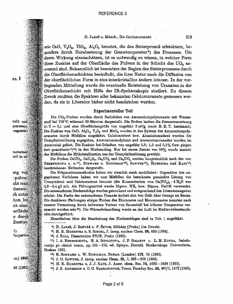
.. ...-. .... D. JAxs9 u. Mitarb., Die Calciumuranate 219
, wie CaoO, V205 , TU0 2, A120 3 benutzt, die den SinterprozeB erleichtern, be-4I_ sonders durch Herabsetzung der Grenztemperatur 9) des Prozesses. Um
d'. - .deren Wirkung einzuschgtzen, ist es notwendig zu wissen, in welcher Form*i *.. ese Zustze auf der Oberfliche des Pulvers in der Schicht des UO an-
.- wesend sind. Bekanntlich ist besonders der Beginn des Sinterprozesses durchS die Oberfldchenschichten beeinflu13t, die ihrer Natur nach die Diffusion von
.:•..: i der oberfl~chlichen Form in eine interkristalline 6ndern k6nnen. In der vor-M-f: liegenden Mitteilung wurde die eventuelle Entstehung von Uranaten in der
*.: : Oberflichenschicht mit Hilfe der IR-Spektroskopie studiert. Zu diesem, Zweck multen die Spektren aller bekannten Calciumuranate gemessen wer-
: den, da sie in Literatur bisher nicht beschrieben wurden.
.". .• ........ Experimenteller TeflDie 'f0 2 -Proben wurden durch Reduktion von Ammoniumpolyuranate mit Wasser-
telit un•d stoff bei 700 0C wihrend 60 Minuten dargestellt. Die Proben hatten die Zusammensetzung
•emessef0~ 0:OU 2,1 und eine Oberflchengr6fle von ungef~hr 8 m2/g (nach B. E. T. bestimmt).,usgesetzt v Die Zustze von OaO, A1 2O,, V2O5 und MOO, warden in das System des Arummniumpoly.
. uranates durch Mitffllen eingeffihrt. Calciumnitrat bzw. Aluminiumnitrat wurden der.:l .r! Uranylnitratl6sung zugegeben, Ammoniurmmolybdat and Ammoniumvanadat warden im
Ammoniak gelost. Die Zusftze bei Gehalten von ungef~hr 6,0; 1,5 and 0,5% Gew. gingenfast quantitativ8 ).0 ) in den Niederachlag. Nur bei einem Zusatz von 60% wurde anstatt
7acteriz,•aOin ii• •}'des Mitfifllens die Mitkristallisation aus der Uranylnitraflisung gewxhlt.0Die Proben CaUO•, C&UO, CU0, und Ca•UO warden hauptso.hlich nach den von
, BEREZNIKOVA u. a. 11), STEWARD u. RUNcIMA-N'2
), SAWYER"S), HOEKSTRA und KATZ' 4)".. t i:!•: beschriebenen Methoden dargestellt.
mg vod.i"'- Die Pr~parationsmethoden haben wir ziemlich stark modifiziert: Gegenfiber den an-
:pU i ~gegebenen Verfahren haben wir zum Mfiitfhllen die berechnete gemischte L6sung voncht• man•, ~ Uranylnitrat und Calciumnitrat benutzt (die Konzentration von Ca(NO,)g . 4 HO war
hee 0,2-0,4 g~l ml). Ala Flllungsmittel wurde 25proz. NH, bzw. 2bproz. NaOH verwendet.
..... .Die entstandenen Niederschl~ge wurden getrocknet und entsprechend den Literaturangabench nt ; erhitzt. Die Farbe der entstandenen Uranate Kndert sich von Gelb fiber Orange zu Braun.
hon bef Die dunkleren Ffrbungen einiger Proben des Diuranates und Monouranates konnten nach
At eine•' unserer Vermutung durch teilweisen Verlust von Sauerstoff bei h6herer Temperatur ver-,erfl.ch... .. ursacht worden sein'5). Die Wfrmebehandlung wurde an der Luft im Elektrowiderstands-....:•'..... ..
•r duro-i . ofen durchgeffihrt.Einzelheiten fiber die Bearbeitung des Niederschlages sind in Tab. 1 angefiibrt.
Zusatz8) D. JA&x., J. BEovik u. F. Sirvon, Silikity [Praha] (im Druck).
1). ;:• •)H. R. HOEKSTRA U. S. SIEGEL, J. inorg. nuclear Chem. 26, 693 (1964).?ropereE 10) J. guLc, Dissertation FTJF, Praha (1963).
11) 1. A. BE.EZxIKOVA, E. A. IPPOLITOVA, J. P. Snu&ANov u. L. M. KOVBA, Issledo-vanija po chimii urana, pp. 151-163, ed. Spicyn, Zbornik Moskovskogo Universiteta,
•.;• 1Moskau 1961..• : ' 12) R. STEWARD U. W. RUCoIMAx, Nature [London] 172, 76 (1963).
on] 1955?i' -1) J. 0. SAWYER, J. inorg. nuclear Chem. 25, 7, 899-902 (1963).* 14) H. R. HOEKSTRA U. J. J. KATZ, J. Amer. chem. Soc. 74, 1683-1690 (1952).
66 (1961)4 15) J. S. ANDERSON u. C. G. BARACLOuGH, Trans. Faraday Soc. 59, 487/7, 1572 (1963).
Page 2 of 5
REFERENCE 3
220 Zeitschrift fur anorganische und allgemeine Chemie. Band 847. :
Tabefle 1Darstellungsbedingungen der einzelnen Uranate
[966
Uranat Flillungsmittel Glilhtemperatur Gltihdauer j Farbe des Produktes
CaV2O7 IX-H10H 900 ±- 20TC 10 Std. helibraun (dunk-Methode I ler als CaUO4 )
CaU2O, NjaOH 900 ± 200C 10 Std. hellbraun (dunk-Methode II let als CaUO4 )
CaU207 I NaOH 12004- 20° 10 Std. hellbraun (dunk-Methode II let als CaUO4 )
Ca 2UO, NH 4 OH 1200 "1250 C 3 Std. hellgelbCa 3 UOG NH 4 OH 900-100TC 5 Std. klargelb
Die Analyse des Diuranates, das mit Ammoniak gefillt wurde, ergab einen geringeýreCa-Gehalt und damit auch einen geringeren Wirkungsgrad des Mitfiflens. In den andereF•Ifen trat dies nicht ein, und es war nicht notwendig, NaOH als Fillungsmitte] zu binutzen.
Die R6ntgenaufnahmen wurden nach DEBYX-SCHERRER mit CuKMx-Strahlung in eiKamera von 114,8 Durchmesser ausgeffihrt. Die Innenspannungen der Proben wurden nacder Methode cosec e= f (0) beobachtet"l).
Die IR-Spektren wurden mit dem Doppelstrahl-Photometer Zeiss Jena, Modell.1gemessen. Die Proben ffir die Messungen wurden nach vorherigem Zerkleinern im Kugevibrator in der Form von Suspensionen in Paraffin61 vorbereitet und in KBr-Kiivetti(0,02 mm) im Bereich von 400-2000 cm- 1 durchgemessen.
Ein Teil der U0 2 -Proben wurde ohne vorherige langfristige Exposition an der Lund der andere Teil nach einige Monate dauernder Exposition in der Atmosphare.id1Laboratoriums gemessen. Ein Teil der Proben wurde bei schwach erh6hter Temperati(ungef•hr 4000) exponiert.
Ergebnisse und Diskussion
Die Eigenschaften der Calciumuranate
Durch die Ri6ntgenogramme der Calciumuranate wurde bewiesen, dales sich um die gesuchten Verbindungen handelt. Da in der Literatur keinDaten ilber das Debyeogramm des wasserfreien Calciumdiuranates vorlegen, geben wii es in Tab. 2 wieder. Diese Verbindung geh6rt offenbar wede
dem kubischen noch dem tetragonalen System an.
Das R6ntgenogramm der mittels Fillung dargestellten Probe des Diuranates (nac]Methode 1) entsprach dem Calciummonouranat, was auch reoht gut mit den Ergebnissii3der chemischen Analyse iibereinstimmte. Das nach Methode 2 dargestellte Calciumuranaver!Lnderte sich nicht einmal durch Ausgliihen bei 1200 00.
Nach unseren Erfahrungen vermuten wir, daB die Methode, welche d4!
Mitfiillung ausntihzt, brauchbarer ist als die Uibliche Mfisohung, z. B. U 3O
16) L. I. M•ERK_, Spravotschnik po rentgenostrukturnomu analysu, Moskau 1961..
Page 3 of 5
REFERENCE 3
D. JAxE. u. Mitarb., Die Calciumuranate 221
.wit CaCOs usw. Nach unserer Methode ist es miglich, eine innige Berihlirungaund deshalb auch eifen besseren Reaktionsverlauf im allgemeinen bei derI)arstellung der wasserfreien Uranate zu erzielen.
Modeim KIK.-VE Abb. 1 gibt die IR-Spektren der Calciumuranate und Tab. 3 die Wellen-
zahlen wieder. Das IR-Spektrum des Diuranates, welches durch Glithen bei900 °0 dargestellt wurde, untersoheidet sich von der bei 1200 0C gegliihtena der I
sphre.'empera
)sen,
tur k(38 VO]
)ar wt
ztes (I
Probe in der Intensithit der Bandenim Bereich von 800 cm-'.
Es ist bekannt, daB die Frequenz derasymmetrischen Valenzschwingung derUranyigruppe in den meisten Uranylsalzeneinen Wert von ungeffihr 900 cm-' hat,whrend der Wert der symmetrischen3ehwingung wesentlich tiefer Hiegt. Wennwfir auch fiberzeugt sind, daB es sich inden Spektren, die in der Tab. 3 angegebenfind, prinzipiell um die Schwingungen derUranylgruppen handelt, versuchten wirtorliufig nicht, die einzelnen Banden zu-
Tabelle 3Wellenzahlen der Hauptbanden in
den IR-Spektren von Abb. 1
Ver-bindung Wellenzahlen (cm-)
caUs,OCaU2O,C&UO,Ca3 UO,caluo.
810 S
811 8854 S814 S
840 m
770S760 S835 sh730 S795S
812 m 740S
737 n 693S
S = stark, m = mittelstark, sh = inflex
I~rgebniss'.iururah
iuardnen, weil in den Uranaten eine starke Beeinflussung der Sohwingung der Uranyl-gruppe durch die Nachbaratome des Sauerstoffs m6glich und za erwarten ist.
"elche dB. 1i
au 1961.
Die gewonnenen charakteristischen Spektren der Uranaten k6nnen zurraechen Bestimmung der Pr~parationsprodukte gut beniitzt werden. Wirmaben uns davon bei der Bestimmung des durch die Methode I und 2 dar-gestellten Diuranates ftberzeugt.
Page 4 of 5
REFERENCE 3
222 Zeitschrift fi~r anorganische und allgemeine Chemie. Band 347. 1966
Die Oxydation des Urandioxides mit 5% Gew. CaO
Das reine, durch die Reduktion in Wasserstoff bei 800 'C dargestelltUrandioxid (Oberflchengr6Be 8 m2/g) wurde an der Luft leicht oxydiert. Djentstandene Oberfl~chenschicht hat im IR-Spektrum 2 Banden bei etw
720 und 900 em-i (Abb. 2). Ehandelt sich wahrscheinlich ux
A •das amorphe UO 3)4).
4 Die Probe U0 2 -5% Calhat ein IR-Spektrum, das sicvon demdes reinenUO2 nichtsel
2 unterscheidet (Abb. 2). Wen
? - -hdiese Probe der Oxydation a.500 60O cm-1 700 800 gO0 1000 1100 der Luft im Laboratorium wiTh
Abb. 2. IR-Spektren: 1. reines UOa, 2. oxyd. rend 7 Monaten ausgesetzU02, 3. Uo, - 6% CaO, 4. oxyd. UO - 6% wird, tritt bei dieser Probe fuCaO. Die Spektren der einzelnden Verbindungen eine sehmale Bande im Bereic.sind auf den Abbildungen gegenseibig in derRichtung der Aohse der IntensitYten verschoben,
damit sich die Kurven nicht sohneiden den Spektren des auf Abb..angegebenen Uranates zeigt, d4.
diese Verbindungen auf der Oberfl~che des Pulvers nicht entstehen, weni•stens nicht in solcher Menge, welche bei gew6hnlicher Empfindlichlkeit debenutzten Methode bestimmt werden k6nnte. Das auf der Oberflache extstehende Uranoxid ist nicht geniigend aktiv, auch wenn seine Partikelikleiner als 100 A sind und die Oberfldchengr6Be also ungefghr 700 mn/i-betrigt. Die durch Mitfdllen eingefiihrte CaO-Zugabe wirkt auf das Oxid alStabilisator, wogegen das in der Laboratoriumsatmosph.re belassene reinUrandioxid nach sieben Monaten fast volikommen zum UO 2. oxydiert wa.
Re. bei Prag, 6SSR, Institut fUr Kernforschung der Tschechoslovakischen Akademie der Wissenschaften.
Bei der Redaktion eingegangen am 25. Januar 1966.
Page 5 of 5
REFERENCE 4
.: I .;. .....
....... .....
GMEL1NS HANDBUCIIA.,.EI
DER ANORGANISOHEN tDHEMI
!...............
AGHTE VOLLIG NEU BEARBEITETE AUFLAGE
H.ERAUSGEGEBEN VON DER
DEUTSCHEN CHEMISCHEN GESELLSCHAFTL '
BEARBEITET VON
R. J. MEYER
STELLVERTNETENDER REDAKTHUR
ERICH PIETSCH
STATNDIG NEUTAEBEITER DER REDAKTION
FRIEDRICH STRUWE, EMMA HALLER, RUDOLF SAHMEN,MAX DlU MATRE, HERTHA GRUSS, ALFONS KOTOWSKI,ADRIENNE EISNER, GERTRUD GLAUNER-BREITINGER,GEORG NACHOD, GEORG BLINOFF-ASHAPKIN, FRANZSEUFERLING. BRUJNO GROSSE -EGGEBRECE1T, LEONARD~EDENS, HANS WOITINEK, WILHELM STOFFERS, ROSTISLAW
GAGARIN, HEINZ GEHLEN, HERMANN SCHNELLER
1935 .
BERLINVERLAG CHEMIE, GMBH
PRINTED IN GERMANY
' V i
Page 1 of 5
REFERENCE 4
230 U URAN UND CALCIUM. 55
L shichkeit bei gewobnl. Temp.: 3.818 g/roo T). H2 0 und 0.0-3 g/ioo TI. Alkohol, R. ERB (I. e.S. 126).
Auxf der Bildg. dieses Tripelacetats beruht ein empfindlicher Nachweis von Na, s. besonders .E. KAHANE (BI. Soc. chaim. [41 47 [19301 382) mit zahireichen Literaturangaben.
Magnesiumunranylphosphat M1g (UO)jPPO4 ) 2. 8 JIO. Kommt nat'irlich vor als Saleit,s. ,,Vorkommen" S. 29.
Uran und Calcium.Calciumumranate.CaU0 4 (normales Uranat). Entsteht durch Umsetzung von UO2C1O mit OaCl, in verd. wss. d
Lsg. bei Ggw. von ftberschiissigem NH2 , W. OEOHSNER DE CoNZnqwc (BI. Acad. Belg. 1909 835).BiMdet sich sehr langsam beim Schmelzen von U.Os mit 0&a0, in Form einer krystallin. r'uste, die Sdiu'ch Ausziehen mit H20 von NaO 2 befr'eit wird. Gelbe Blttchen, A. DITTE (C. r. 95 [1882] 990; IAnn. Chim. Phys. [6] 1 [r884] 352).
CaO- 2 UO (Diuranat). Bildet sich nach A. v. UNRuH (Dissert. RoStock 1909, S. 12) bei Einw. hvon GaO auf eine Ether. Lsg. von kyst&allisiertem Uranylnitrat. - Darst. der kIystallisierten Verb. Idurch Gliihen von gefllter Uranse.re mit GaOl2 wie die entsprechende Ba-Verb. (S. 2-33), nur lang- Cearner, V. FISOHEL (Disse•t. Bern x889, S. 21). - Beim Erhitzen von U,08 mit Ca(C010,. trittvolstlindige Umwandlung zu amorphem Uranat ein, das sich dutch Sohmelzen mit NaCI oder GaO!lin die lk-ystaflisierte Verb. iiberffihren 118t; die Krystallisation erfolgt sehr langsam. GelbgraneBliittchen; un]is]. in H.0, Isl. in verd. Sluren. Sehr strengibissig; fiirbt sich bei langemn Erhitzen [aui helle Rotglut dunkler und wird gleiehzeitig sohwerer 16sl. in verd. Siuren, A. DITTE (C. r. 9• d[1882] 990; Ann. Chirn. Phys. [6] 1 [1884] 353).
Calclumperuranat Ca 2UO"- 10H.O. Entsteht dutch Umsetzung des entsprechenden I
Na-Salzes mit CaGCI als hellgelber, krystallin. Nd., der aus rhomb. Prismen besteht. Wird dureli zH2 S90 unter Abspaltung von H1103 zersetzt, P. MELIKOFF, L. PISSARJEWSKY (Ber. 30 [1897] 2906). I
Calelumuwran (IV)-chlorid CaCL.- UCI, oder CaUCI,. Darst. und Eigenschaften vie beim zentsprechenden Ba-Salz (S. 234), J. ALOY (Recherches sur M' Uranium el ses Composes, ThAse Toulouse il290o, Nr. 21, S. 18; Bl. Soc. chim. [31 21 [1899] 265). d
Calciumuranylearbonate.Oalciumuranylcarbonat kommt in der Natur ver als Uranothallit, dem die Zus. CaZUO.(M0.)
xoH 2O zugeschrieben vird (manchmal in der Literatur ale Ca2U(CO)•- 0oH10 angegeben), fernerale Liebigit, s. unter ,,Vorkommen" S. 22. .0
CaCO2 . UO1C03. 10 HO oder CaUO 2(C0 3).. ioH2 O. Bildet sich aus Calciumuranat in Be- 4
rilhrung mit CO und etwa 8oo cmO HO unter Dmck innerhalb von 2 Jahren; die Fl. fMrbt sich hiintensiv gelb, und der Nd. verwandelt sich in kleine, tafelfdrmige Krystalle obiger Zus., C. BLINKOFF h
(Dissert. Bern 19o6, S. 36). - Das Doppelsalz liflt sich durch Umseezung von K4U02 (C0O),-Lsg. 4 Iin der Kilte mit Caleiumsalzlsg. nieht darstellen, J. A. HEDVALL (Z. anorg. Ch. 140 [1925] 227).
2 CaCO,. UO.CO. 3 UO,. 22Ho0 oder Ca2UO,(C0) 2 - 3U0%" 22H..0 (bas. Salz). Calcium- furanat wird bei ro Atm. Druck mit CO in Ggw. von 400 cm2 H20 behandelt. Es bilden sich hellgelbe,quadrat. Thfelehen, 0. BLINKOrF (Dissert. Bern 19o6, S, 34).
Calclumuranylacetat Ca(CH:,COh.)"2UO. (0H 2•Oj"(6 bis 8) 11.O oder Ca(UO),(0112
C0%)," (6 bis 8) H,0. Wird aus Lsgg. entsprechender Mengen der Einzelacetate und Umkrystalli- Vsieren des Nd. aus essigsaurer Leg. Von P. WESELSKY (J. pr. Ch. 75 [18581 56, 6o) in schwefel-gelben, Juftbestindigen Krystallen mit 811•0 erhalten. Nach C. RAm/mELSBERG (Ber. Berl. Akad. f1884 866; Wied. Ann. 24 [z885] 301) seheiden sich aus solohen Lsgg. kleine, undeutliche Krystalle • rmit 6 bis 7 H1O ab. -- Die Verb. entsteht nach J. WERTnEhi (J. pr. Ch. 29 [1843] 231) analog den IAlkali- und Ei'dalkaliuranylacetaten. - Rhombisch bipyramidal. Krystalle mit flachenreichenKombinationen. Achsenverhbiltnis a:b:c=o.9798:I:o.3865. Keine deutliehe Spaltbarkeit. Doppel-breohung positiv. Griinliehblaue Fluoreseenz, GnOTB, Bd. 3, S. 84, nach den Messungen vonJ. GIUMICIo (Kyslallographisc-optische Untersuchungen, Wien-Olmrii 1858, S. 259); s. auch g
C. RABM[ELSBERG (L c.), V. v. LANG (Bet. Wien. Akad. 31 [z858] z07, Z26). - Verliert naehP. WESELSRY (I. c.) bei 2oo0 des Hydratwasser. Diese Beobachtung kann von C. RAMSELSBElmE(I. e.) nicht bestfitigt werden. - Leicht 1691., J. WERTHEJM (1. c.). I
Page 2 of 5
REFERENCE 4
7m,
65
R. Enn (I.".
s. besonders
55 CALCIUiMU RAN YLO RTHOPHOSPHAT. U 231
or ala Sialeit,::";
in verd. wBs.909 835). -
Kruste, die$ [r88 990;.
12) bei Einw-.isierten Verb.,13), nur lang-"'::.•(lJ.tritt'i.•.CI oder CaCl"i. Gelbgrn:..:.emai I!jhit enV.
Trill (0. r.9
itsprechenden ...Wird durch."i-
[1897] 29o6).[ten wie beim'Uhse Toulouse
Ca.UO,(C0,), *1geben), ferner.
uranat in Be-,Fl. frbt sichC. BLINNOEP..
[9251] a27)..:,alz). calcium-".sich hellgelbe"
Ca(U,).(CHý'.:: AI Umkrystalli-ii) in schwefel-er. Berl. Akal'.:.tiche Krystalle : '31) analog den:..:.flicohenreichen.
xkeit. Doppel-.ltessungen von,159); s. aauclh!.
Verliert achli.RAmMEL5DE1IG
Calciumuian(IV)-hydaoomalat CaCO,.0 U E7(C20 4)2"H, .1 04 2•4H.O oder CaHUT,(C,0 4),•2411,0. Dutch Versetzen einer salsauren UCl1-Lsg. mit CaC4 umd Oxalsaure. Feine, weijie,verfilzte Nadeln, H. Rossi (Dissert. Manclhen 1902, S. 45).
Alkalicaleiu.mnuvan(i.V)-oxalate.NaC•0 4*CaC.0O U(C0.•),'8 1H10 oder Na.CaU(C20,)4 . 8 H,0. Aus dem entsprechenden
K-Ca-Salz dnrch Umsetzung mitt NaCl. Helirote Krystalle. Schwerer 16si]. als das K-Ca-Salz, R.Rossi (Dissert. MNinchen 1902, S. 41). -- Monoklin. Einige krystallograph. Angaben s. F. SLAVwK beiH. Rossi (I. c. S. 42); vgl. auch GROTH, Bd. 3, S. 135.
JiC,0 4 ' (JaG,0 4 ' U(C20 4 )2 -811H0 odor K2CaU(C,0 4)4. 811,0O. Darat. analog demn K-Sr-Salzdiunch Versetzen einer Lsg. von iiberschfissigem K4U(C,04 )4 mit verd. OaC4-Lsg. Rotviolettes,brystallin. Salz. Wenig ldsl. in H20, daxraus umkrystallisierbar, H. Rossi (Dissert. Manchen 1902,
S. 40). - Unter dem Mikraoskop monoldine Tafelchen, F. SLAviK bei Rossi (0. 0. S. 41); vgl. GROTH,
Bd' 3, S. 135.Calciumuranyloxalate. Durch Umsetzung von Alkaliuranyloxa]aten mit CaI, werden
keine definierten Oa-Verbb. erhalten, A. RosENmIEix, H. LiENAU (Z. anorg. Ch. 20 [1899] 288).Ebenso wird innerhalb des untersuchten.Systems CaC,0 4-U0•OC0-HO bei 150 und 50o keinCalciunm'anyloxalat als Bodenkdrper beobachtet, A. COLANI (C.r. 198 [193] I51O; Bl. Soc. chim.:5] 1 [934] 1376).
Calciumuwan(lV)-orthophosphat CaU(PO,),. Entsteht beim Zusammenschmelzen voni TI.. Uran(IV)-metaphosphat mit 5 TI. wasserh'eiem Ca&CI, A. OoLAXz (Ann. Chim. Phys. [8] 1211907] 140). Grine, monoldine, pleochroit. Krystalle mit dem Achsenverhiltnis a:b:c = 1.508:*1:1.124, P = 930 29'. In Sguren praltisch unldsl., A. DE SO•HLTEN, bei A. 0oroNr (1. o.).
Calciumuranylorthophosphat Ca(UO,)2(POd,. -x H1O (kiinstlicher Autunit). Bei sehrlangsamem Diffundieren von Uranyl- und Calciumnitratlag. in stark verd. HP04 -Lsg. scheidet sichzundichst ein amorpher Nd. aus, der bei ruhigem Stehen nach etwa einem iMonat in die krystaulineForm fibergeht unter Bildg. grolier, plattenfdrmiger Krystalle. Oder man fdigt nach dem Aussalzverf.zu einem Ldsungsgemisch von Ca-Hydrophosphat umd Uranylnitrat CaCI,, wobei 4- und 8seitige,isotrope, doppelbrechende, graublaue Tafeln exitstehen. Bei einem Wassergehalt von 13.84% istdlie Brechungszahln. i.6oo und nt = i.590. Bei einem andern Prod. mit 15.42% HO ist n. =1.598 und n. = 1.586. Ca kann teilweise oder ganz durch ein anderes Metal] ersetzt werden, indemman zum Aussalzen die entsprechende Chloridlsg. verwendet. Auf diese Weise k6nnen Autunitemit Na-, K-, Mg-, Ba-, Pb-, Mn-, Ni-, Co- und CO-Gehalt erhalten werden. Reiner Na-Autunirtohne Ca-Gehalt wird aul3erdem durch 2tAgiges Behandeln von Ca-Autunit mit halbgesitt. NaC1-Lsg.auf dam Wasserbad erhalten, J. G. FAiiromL (Am. Mineralogist 14 [1929] 265).
Beim Zusammengielen einer angesduerien Ca-Hydrophosphatlsg. und UranylniWtratlsg. imn Ver-hb[tnis Ca: U = ': 2 krystallisiert ein Nd. aus, der ars sehr kleinen, durchsichtigen, quadrat. Tbdfelohcnbesteht. Nach dam Wasohen und Trooknen &iber zo%igem H2SO4 enthi.lt das Prod. etwa io MolH,.O. Ans dam Verlauf der Dampfdruckkurve naoh VAN Bw LrEN bei x5S geht hervor, daB es zweiHydrate gibt, ein 8- und ein zo-Hydrat, die ineinander weitgehend Idsl. sind; ferner existierenJeste Lsgg. des 8-Hydrats im Anhydrid von hoher Konz.. Auf diese Weise kannte man die wider-sprechenden Angaben fiber den Wassergehalt des Autunits erkliren, A. BERGMAN (J. Russ. Ges.[chem.] 56 [1925] 226; C. 1926 I 1097). Natdirlicher Autunit reagiert mit COOl, bei 8ooO unterBildg. von ffiichtigem UCI4, wihrend CaC, zauriichbleibt, J. BARLOT, E. CHAUVVNET (C. r. 157[1913] 1154).
Calciumuranylhydroorthophosphat OaUOH,(PO,•. . 1H1O. Das satire PhosphatUillt in Form zitronengelber Krystallkrusten beim Mischen von konz. CaHPO,-Lsg. im l0bersohuBmit Uranylnitratlsg. Bei einer Bildungstemp. von So° bis 6o0 enth~lt es 4 Mol 11•0, bei 100o 3 Mol'H20 und bei 2500 • m geschlossenen Rohr 2 Mol HO, H. DEBRAY (Ann. Chim. Phys. [3] 61 [1861) 446).
Basisehe Calciumuranylphosphate. Beim Erhitzen einer Lsg. von Ca,(PO), in HNO%mit einer wss. Uranyinitratlsg. (i Mol CaO auf 2 Mol UO) im Bombenrohr aulf 2oo0 bilden sich quadrat.,gelbe Tgelchen von der Zus. 3 CaO. 5 UO, 2 P.0, -x 6 HO, C. BLINKOFF (Dissert. Bern 19o6, S. 14).
Calciumw'anylarsenat Ca(UO,)2(As04)2.8 H20. Aus einer Lsg. von Ca(OH), in fiber-schiissigem HOAsO, f5llit auf Zusatz von Uranylnitrat kiinstlicher Uranospinit, C. WINicLER (J. "'.Ch. [2] 7 [j873] 14).
ii
~il
Ii'
Page 3 of 5
REFERENCE 4
282 U URAY UND STRONTIUM.
Uran und Strontium.Stiontiumuranaie.
Sr'UO4 (normales Uranat). Entsteht durch Umsetzung von U02 012 mit SrCl0 in verd. WssLsg. bei Ggw. von iibersohiissigem NH3, W. OnHSiNER DE CONTINOK (BL Acad. Belg. 1909 835).Darst. und Eigenschafteni der r-ystallisierten Verb. wie bei CaUO4 (S. 23o), nur erfolgt die Krystalli.sation .noch langsamer, A. DITTE (C. T. 95 [1882] 99o; A-nn. Chirn. Phys. [6] 1 [1884] 353).
SrO. 2U0, (Diuranat). Entsteht dutch Fillung einer Lag. von Sr(OH), mit Uranylnitra• ala
orangegelber, in H1O sehr sahwer 16sl. Nd. der Zus0.r 02 U03 . H0, der bei starkem Giihen in braum.lrotes, wasserfreies Salz iibergebt. Leieht a6sl. in Siuren, besonders in Oxalsaure; die oxalsaure 14.scheidet beim Eindampfen lange, zerflielliohe Nadein ab, J. (Osterr.-ungar. Z. Zuckweind. 25 [r~g(19q445). -. Darst. der krystallisierten Verb. analog CaO.2 U01 (S. 23o) nach den Verff. von A. DrT*a(C. r. 95 [1882] 99o; Ann. Chinr. Phys. [6] 1 [1884] 354) und V. FiascHL (Dissert. Bern 188g, S. 2 .);die Krystallisation erfolgt noah langsamer als die der entaprechenden Ca-Verb., A. DITTE (I o.);
Str•ontiumuran(IV)-chlorid SrCI,. UCL, oder SrUOI6. Darst. und Eigensohaften wie beh&entsprechenden Ba-Salz (S. 234), J. ALOY (Recherches sir 1'Uranium el se8 Composds, Thkde Toulouse19or, Nr. 21, S. xS; Bl.Soc. chirn. [3] 21 [1899] 265).
Strontiumuranylcarbonat SrCO,. UO,003 . U0-. 10 HtO (bas. Salz). gine SuspensioiijNvon Strontiumura.nat in H110 wird bei 1o Atm. Druck mit 00. behandelt; die Verb. acheidet aich'ala amorphes, gelbes Pulver ab, C. BLINKOFF (Disseri. Bern a9o6, S. 40). - Bein Versetzen aerMK4UO,(C02 ),-Lsg. mit Strontiumsalzlsg. entsteht allmiihlich ein hellgelber Nd. in geringen Mengenna,der sohon kurz nach dem Ausfallen siabtbare CO-Entw. und allmihliahe Farbinderunig infolge -
Hydrolyse zeigt, J. A. HEDVALL (Z. anorg. Ch. 146 [1925] 227). - Beim Koahen tritt Zers. ein l•gerCO,-Entw. und Abscheidung eines krystallin. Pulvera, C. BLNKOFF (. a.).
Strontiumuranylacetai Sr(CHCO.).. 2UO,(CH3 CO1 ),.6 H.0 odor Sr(U02,)2(C11c302)S.6HO. Aus Lsgg. entsprechender Mengen der Einzelacetate und Umkrystallisieren des Nd.'aug rK
essigsaurer Lsg.; Farbe und Eigenschalten der Krystalle wie beimr Ca-Salz (S. 230), P. WE.ELS.cy(J..pr. Ch. 75 [z858] 56, 61). - Entsteht nach J. WERTH•iM (J. pr. Ch. 29 [1843] 231) analog deiAAlkali- und Erdalkaliuranylacetaten in undeutliahen Krystallen (keine Formel angeg6hen)..-Von C. RAi=aaELSnER (Ber. Berl. Alcad. 1884 865; Wied. Ann. 24 [1885] 301) konnten ama der •atrk.effloresaierenden Lsg. keine melbaren Krystalle isoliert werden. - Dit•tragonal skalenoednseh.,ŽAchsenverhiiltnis a: C = 1:0.3887, J. GRAIICH (Krystallographisch-optische Untersuehungen, Wi01mOlz 1858, S. 161); s. auch C. RAnxsuanno (L. c.), GRoT•r, Bd. 3, S. 84. - Verliert das Hydrat.wasser bei 2000, P. WESELSKY" (I. C.). - Leicht idsl.,. J. WERTHEIBI (L a.).
Strontium Turanyloxalat SrC9O,. UOCO2,O 4 H20 odor SrU02(C2O1)2 -4H2O. Trittails 5' 11'einzige Doppelverb. innerhaib des mntersuchten Systems SrC.0 4-UO.C,0 4 -HO bei 15O undauf, A. COLANI (C. r. 198 ['9341 151o; BR. Soc. chim. [5] 1 [1934] 1376). - Von A. ROSENEIM',H. LIENAU (Z. anorg. Ol. 20 [z899] 288) konnten keine Sr-Verbb. erhalten werden.
Kaliumstoronttumuran(IV)-oalat 1 C20,.4 SrCO4 . U(C,ýO,),. 8 H.O odor K2SrU(C30) 4O8HO. Durch Versetzen einer Lsg. von iUberschtissigem KU(C.O.) mit verd. SrCl-Lsg. Blalfhfa
larbene, tafelfOrmige Aggregate, H. Rossa (Dissert. Mfinchen 1902, S. 37).Ein entsprechendes Na- and NH-Salz ist nieht darstellbar, H. Rossi (1. c. S. 39).
Stronfiumuran(IV)-orthophosphat SrU(POJ,). Entsteht beirn Zusammensohmelzeftvon i T1. Uran(IV)-metaphosphat mit 5 TI. wasserfreiem SrCI2. Griine, pleochroit., rhomb., d unneTidelchen. Achsenverhiltnis a:b:c '- .474:1: 1.165, A. COLAHI (Ann. Chim.Phys. [8] 12 [1907] 141
Nd. auf Zusatz von Phosphorsam'e zu einer salpetersauren Lag. von Sr-Nitrat und UranvYnitraC. BLINKoFF (Dissert. Bern r9o6, S. 20).
2SrO 5.U0," 2 P,05 " 24H2,0. Entsteht wie die vorhergehende Verb., nur in wss., neutraleLag., C. BLINKOFF (Disseit. Bern r9o6, S. z20. I
.:A'. I
Page 4 of 5
REFERENCE 4
L verd. wMsS~~,'09 835).ie Kryst:alli- .4..
.53). -
'yifitrat als -en in braun• n7alsaure Lsg"'Id. 25 [18961.:-i.:.on (A. DaTT)::'x889, S. O:i:i
en wie beimnŽ4se Toulouse
Suspension'.aheidet sich :-setzen. elne•-r:,enl Mengen;j~rung infolge'.,is. ein unter:j
j•(0113'...S
des Nd. ans. :
analog den.egiben).,us der starkilenoed'iscliu:ngen, w n-das Hydrat-':
Tritt. ais '5o and ; o :
{.SrU(OU.O•) ',g. Blafflila-
.enschmelzeftomb., dinnie.-
[1907] '41).'
rokrystalhin...Ulranylnitratr.
i0
55 URAN UND BARIUM. U 233
Uran und Barium.Ba•iumuvanate.BaUO4 (no•males Uranat). Entsteht nach W. OncHsainR DE Comowk (B1. Acad. Bedg. 1909
835; 0. r. 148 [1909] .77o) durch Umsetzung von U0 2C12 mit Ba~l2 -in verd. Wss. Lsg. bei Ggw. voniibersahfissigem NH3 . Dieselbe Meth.1.ffiiht nach AIteren Angaben zur Bildg. von Ba-Dim'anat (s.imten). - Darst. der laystallisiertexi Verb. durch Schmelzen von U, 08 mit BaCl wie die entspreahendeCa-Verb. (S. 230), mill erfolgt die Krystalilsation sehr viel rascher. Bildet gldnzende, gelbgriineBlIttehen, die sih in -warmem verd. HCL Ibsen, A. DITTn (0. 1'. 95 [1887.] 990; Ann. Chlim. Phys.(6] 1 [18&4] 354).
BaO.- 2 UO, (Diuranat). Entsteht dur'h Fillung einer sd. Lsa. von UO•C.2 und BaC12 mit fiber-
schiissigem NH,; der abfiltrierte Nd. wird m6g]ichst schnell mit sd. H.O ausgewaschen (um Ver-inreinigung durchBa0OQ zu verhindern) and dann getrocknet and gegliiht, J. A. A.RPvEisON (Svenska
Akad. Handl. 1822.417; Pogg. Ann. 1 [1824] 260). Da die nach der vorstehenden Meth. erhalteneVerb. burner NH 4-Uranat enthalten soll, wird von J. J. BEniZELIUS (Pogg. Ann. 1 [1824] 370) folgendeArbeitsweise empfohlen: Fiilen von Uranylnitrat mit Ba(OH)1 and Auswaschen des Nd., solangedas Wasser noch Ba aufnimmt. - Die dutch Kochen von Uranylnitrat mit Ba(OH)2 in groflem Ober-sahuf hergestelite Verb. soil naah 0. B. KtHN (Lieb. Ann. 41 [1842) 342) annughernd der Zus. BaUOQentsprechen. Dutch Fllung von Uranylacetat mit weniger Ba(OH) , ale zur vollstindigen Zeta.notig ist, wird nach J. WERTHrEi (J. pr. Oh. 29 [1843] z2o) ein carbonatf-eier Nd. erhalten. - Darst.der krystailisierten Verb. du'eh Erhitzeer von U.0. mit Ba(0l0O) 2 analog der entspreohendenCa-Verb. (S. 230), nur erfolgt die Krystaliisation sehr viel rascher, A. DITTE (C. r. 95 [1882] 990;Ann. Chim. Phys. [6] 1 [1884] 355). - Durah kurzes heftiges Ghihen von gefiliter Uransfore mitBaCl2, wobei sich die Sahmelze erst graubraun mnd dans zimtbraun firbt; Weiterbebandlungwie bei K2O: 2 UO3 (S. 19g), V. Fiscer. (Disserl. Bern 1889, S. 2o). - Dubch Glilien von Ba-Uranyl-acetat, J. WERTHEDIE (. c.). Die giinstigste Zersetzangstemp. des Acetate liegt nach J. ZEHENTER(Monaish. 25 [1904] g98) zwischen 3oo0 and sahwacher Roti|ut; bei starker Rotglut tritt weitereZers. ein, die sich durch griinliche Firbung und teilweise Unl6slichkeit des Rilakstands in HCIzu erkennen gibt.
Faxbe der geffillten Verb. gelbrot, nach dem Pulvern orangegelb, J. A. ARFVEDSON (L C.). -
Krystallisiert in gelbgrfinen Blittaben; Verhalten wie bei CaO.- U0% (S. 23o), A. DITT. (). a.).
2BaO" 5 UO•. 8H2O. Dufch Erwhrmen einer wis. Lsg. von Ba-Uranylacetat auf dem Wasser-bad unter wiederholtem Zusatz von H.0, bis die Fl. neutral reagiert; die ausgesehiedene goldgelbeMasse wird abfiltriert, mit heillem H2O bis zum Verschwinden der Ba-Rk. ausgewasahen und an derLuft getrocknet. Man kann auch von Lsgg. der einzelnen Acetate ausgehen, wenn diese ira Ver-bltnis des Doppelsalzes vermischt werden; bei Anwendung von Ba-Aeetat im tbersohufl bildetsich Diuranat. Gleiaht nach Aussehen und Eigenschaften dam Triuranat (s. unten). Gibt bei 1400411, Mo] H11O ab, geht bei Rotglut in wasserfreies Satl fiber, J. ZREsEawmR (Monatsh. 25 [(904] 201).
BaO. 3UO. 4'/2 H•O (Triuranat). Dutch 5std. Koahen einer s%igen Lsg. von Ba-Uranyl-acetat in einer offnen Schale am Riiakflulikflhler als schwefelgelbes Pulver, das abfiltrierlt, bis zumVersahwinden dar Ba- ind U-Rk. mit heidem 11,0 ausgewaschen und an der Luft getrocknet wird.Man kann aueh von r- bis a°/oigen Lsgg. von Ba-Uranylacetat odar von einem L6sungsgemisch dereinzelnen Acetate ausgehen, J. ZEHENTER (Mona•sh. 25 [904] 199). Entsteht ferner aus derMutterlauge von Ba(CH-0C0).3U0~a 8l~/,H10 beim Kochen; wird wasserfrei ala Rdickstand bei derVerbrennung desselben Salzes erhalten, J. ZEHENTER (1. a. S. 208). - Zaigt uinter dem Mikroskopeine ziemlibh einheitliche, aus Kdrnern bestehende Masse. Gibt bei 1400 2'/, Me] H1O ab, den Restbei schwacher Rotglut. Bei'stirkerem Erhitzen tritt wie beim Diuranat weitere Zers. ain, kenntlichan Farbinnderang von Rotgelb in Braun und teilveiser UnlOsliabkeit des Riiakstands in HC1. Fastunl6sl, in H20, KOH and Alkohol. Leiaht 16el. in verd. 1101 oder HNO in der Kftlte sowie in heiBsr"sSigsii1r•., J. ZEHENTER (1. C. S. 199).
Werden i%ige oder noch strker verd. Lsgg. von Ba-Uranylacetat niclit wie bei der Daust.des Triuranats in einer offnen Schale, sondern in einem mit Riiclflulkiibler verbindenen Kolben4 bis 5 Std. auf dem Wasserbad erhitzt, so bildet sich nach J. ZEHFN-TER (I. C. S. 203) eine gelbe,pulvrige Verb., die lufttrocken der Zun. 2 BaO. 7 U0 3 .- 11H.0 entspricht. Erscheint unter demMikr'oskop als einheitlich krystallin. Masse, die aus sechssea•igen Bltttchan besteht. Verliert bei
o00 2•/• Mo] H1O; geht bei schwacher Rotglut in wasserfreies Satl fiber.
F
III
I'd
II
II
ktllII
F i'~fr(
0;
I lir IiIf):
Page 5 of 5
* t
U
* I* I
/
REFERENCE 5
N. P. Galkin, B. N. Sudarikov, U. D.Yeryatin. Yu. D. Shishkov,
and A. A. Maworov
TECHNOLOGY:oF URANIUM"
,i LL .(Tekhnologlya urana)
Edited by N. P. Galkin and' . N. Sudarikov.1?/: .
Approved by the Ministry of aigher aad SecondarySpecialized Educatlon of the RSFSR as
a textbook for students ofchemical technology
Atomizdat
Moskva 1964
.R~lE.ASEID FOR AVNOU!NCEMENI
IN NuclazR -CIEqCE 'ASi tACTS
Tr•zaslated from Russian'-Ar!
r
Israel Program for Scientific TranslationsJerusalem 1906
•OPEN OF GENERAL EL£ECTRI
Page 1 of 3
REFERENCE 5
The solution is then reduced by sodium hydrosulfilt (consumption ofNaAS2 O4 about 0.5 kg/rms of solution); this is accompanied by a quantitativeprecipitation of uranium an a concentrate with a content of up to 20%.Kleselpuhr is addeu to faci i1ate the filtration. After Isolation from thesolution of sodium salts, the precipitate is redissolved in sulfuric acid inthe presence of sodium chlorate: the Kieselguhr to recycled and a purerco-.centrate is precipitated from the uranium solution ibp' the addition ofalkali). The uranium content In the finar product attains 35-50%.
The urariurn is reduced by hydrogen urder pressure as toliowr:
i 'O~to 1, -r s t . --z -,, . 0lo + COt + 2llCOi.
The rate of precipitation in this case is determined by the temperature.the press-re and the surface of the catalyst. The optimum conditiona are:temperature 140-:50% hydrogen pressure 10--13 atmospheres, duration3-4 hours. The nickel catalyst used is in the form of a powder or gauze.The hydrated dioxide is separated from the nickel powder, which remainsunchang'-d during the process, by magnetic separaUon; uranium may beremoved from the nickel gauze by treaitment with a mixture of hydrochloricand hydrofluoric acids. The precipitation of uranium by hydrogen underpressure is quantitative: 2 -3 mg/I remain in the mother liquor.
8.4. PRECIPITATION OF URANIUM FROM ACID) SOLUTIONSBY ALKALIS
Alkaline treatment of uranium solutions is very widely used. It Isemployee. to prt-cipitate the concentrates and to effect advance precipitationof :ertain admixtures (mainly iron) from the process solutions. In thetreatmont of uranium leaches by basic reagents, sparingly soluble nsetalhydroAtdes (*i>Nble 8.5) are formed.
TASUX Li
SohLbLUY Ia etwa a( Cc.•ia Metal hyd, o*X", at 2V
M.ao, ,.Sbiy,. .,t.l solubua.
C4 (01%I voý(oO'*(011H, 1 V( I)79 foII I xlt15'o ALcUq.S/
The precipitation of hydrates takes place at a given pH of the solution(Table 2.6). Quantitative precipitatiov of uranium is noted at pH a 6. MostoW the metals- contaminants-- are coprectpitated with the uranium:calcium and magnesium are not precipitated at this pH; the alkali metals,sodium and potassium remain in solution. The residuaL concent-ation of Zp Lurr'Aium in th4 alkaline solution ;V n tt higher than, I or 2 mg/1, provided ---complexing agents (fluorides, ciu "onates, czalatah--vi'rious organic
208
Page 2 of 3
'A
-4P
REFERENCE 5
[icoal, etc.) are absent. At a high concentration of comptexing &gentainfum cannot be precipitated at all.
TABLZ 8.6
Vaim of pil &I wbkcb nvs hy*axuW gor pcciummd
I.(033), I.S-3.S V. 011hp R.-OTb ',fltij4 3.2.-3.S "I(t~ B.-l'.6. (0i11h 4.4)-3.0 UO 1Oij 6 0-t.U(14 (Ohh, .$.". (Oi~llh It10,(0113, L.JO gOI o
JA the neutralization of phorphoric acid and vanadyl oulfAte (jind alsowaic acid)l in pure solutions, soluble phoaphates and vajadates are
lWO, 04 M1h,O11 4. 4ki~ PO. + 341,4;
(%3 SO,~4iI 2~,0 ~ii~~,ri,
iswell ias acid saztv). H-owever, if uranium and other sdmixwres arejnIt, the reaction becomnts more vomnplcated: insoluble phosphates
.vtnadates of ura~nium "n~ of the admixicrev are formed:
rqgl soluble foriro- adalwnophoaphatea and vanadates are formed~1wsame :rine. For thibz reaioon during thes precipitation of usraniumegntrates by ammonia. uruniurn i s not freed from van..dtum ,.nd
'Pau.The solubility of cotrplar aixnmonfurn uranyl phosphates1wadates is about the same as the solubility of tht dlur4nate. Sincet~admixtures, are coprecipitsited with ur~anum durting die alkalined{iment. the concentrates obtained are rather poor In urenkcm.
05h blises ugod include Mlla~, N11 4021 Ca(OH)1 , 1M;-(CMI{. Skdiurmox-.ide wns emplciyed whena 'he precipitated product sz-rvi'd -is a colorantjlgvaa and worcelain. At present thin precipitant is only mrarly
..played because of its hijdh price. The aihantagen of cadium frrcrovidepr-ecipitant includo its evUcy truanportability; sodium hydroxide is
lymarkveted an a soi~d, packed in hermetically asesald steel druins.liwas assumed until recently that sodium hydrerx.de or aqueoux
Mia reactstawithasolutionseof tzranyl salts with t)he precipitaxlon of Owesqiapoding diur-onates of th? composition hlc2 UAO. It wits found, how-
*r, that the cornpositior' of thie uranium precpiptates Isolated %Ith theQfLl),li4 In not constant ane dependst on manyw factors. the nri-in oneso the uranium con~centration in the startinz solution. excess of
tipitun'. anid the riature of the v4M*on. Nvu'ralization of urtry souinannionta results In the forntation, ftrst Of uranyl isyds-oxide and then
Page 3 of 3
REFERENCE 6
ii
Advanced groundwater remediationActive and passive technologies
BRITISH LIBRARYDOCUMENT SUPPPLY CENTRE
2 3 DEC 2003
,nO3/. 2461
Edited by
F.-G. SimonFederal Izstitute for Mateiials Research and Testing (BAM),Berlin, Gelmany
T. MeggyesFederal Institute for Mateuials Research and Testing (BAM),Berlin, Germany
C. McDonaldSchool of Civil Engineering, University of Leeds,Leeds, UK
'1.' ThomasTelford
Supplied by The British Library - "The wold's knowledqe"~II
Page 1 of 16
REFERENCE 6
Published by Thomas Telford Publishing, Thomas Tclford Lid, I Heron Quay, London E14 4JDURL: hitp://www.thomastelford.com
Distributors forThomas Telford books areUSA: ASCE Press, 1801 Alexander Bell Drive, Reston, VA 20191-4400Japan: Maruzen Co. Ltd, Book Departmcnt, 3-10 Nihonbashi 2-chome, Chuo-ku, Tokyo 103Australia: DA Books and Journals, 648 Whitehorse Road, Mitcham 313_2 Victoria
First published 2002
A catalogue record for this book is available from the British LibraryISBN: 0 7277 3121 1
0 The authors and Thomas Telford Limited 2002
All rights, including translation, reserved. Except as permitted by the Copyright, Designs and Patcnts Act1988, no part of this publication may be reproduced, stored in a retrieval system or transmitted in any form orby any means, electronic, mechanical, photocopying or othenvise, without the prior written permission of thePublishing Director, Thomas Telford Publishing, Thomas Telford Ltd, I Heron Quay, London E14 4JD
This book is published on the understanding that the authors are solely responsible for the statements madeand opinions expressed in it and that its publication does not necessarily inmply that such statements and/oropinions are or reflect the views or opinions of the publishers. While every effort has been made to ensurethat the statements made and the opinions expressed in this publication provide a safe and accurate guide, noliability or responsibility can be accepted in this respect by the authors or publishers
Typeset by Helius, Brighton and RochesterPrinted and bound in Great Britain by MPG Books, Bodmin
Supplied by The British Library - "The world's knowledge"
Page 2 of 16
REFERENCE 6
14. Investigation into calciumoxide-based reactive barriers toattenuate uranium migration
M. C6v&iri, J. Csicsik and G..FoldingMecsek~rc Rt, Esztergdr L-u. 19, H-7633 PNcs, Hungary
14.1. IntroductionPast uranium mining and processing by Mecsek Ore Mining Company in Hungaryhas led to the accumulation of huge amounts of various solid wastes: tailings fromconventional milling, wastes from heap leaching and waste rocks. In total, the wastescontain approximately 2800 tonnes of uranium, of which 500 tonnes derive fromheap leachingwastes, with an average uranium content of approximately 70 gltonne.The wastes also contain a small amount of pyrite (0.1-0.2%).
Remediation aims to relocate all heap leaching wastes (a total mass of 7.2 milliontonnes) to one of the waste rock piles.
14.2. Leaching of uranium and other heavy metals from thewastes
Relocation of uranium bearing wastes is always accompanied by dissolution ofuranium and other heavy metals which are present in the wastes. The main processof this dissolution is associated with the oxidation of pyrite.
Pyrite is oxidized directly and indirectly by ferric ions (Hutchison, 1992; Day,1994):
2FeS2 + 702 + 2H 20 -- 2Fe29 + 4SO 42- + 4H' (1)
4Fe2 + + 10H 20 + 02 -4 4Fe(OH), + 8H+ (2)
2Fe2+ + 02 + 2I-I -- 2Fe3+ + H20 (3)
FeS2 + 14Fe3+ + 8H 20 15Fe2+ + 2SO42- + 16H+ (4)
The sulfuric acid formed reacts with the minerals in the waste (dolomite, silicates,etc.):
CO2 formed in the dissolution process then reacts with additional carbonates,increasing the concentration of bicarbonate ions in solution:
CaCO3 + H2C0 3 ; Ca2 + + 2HCO3- (8)
Sulfuric acid formed in reactions (1)-(4) can react with heavy metal minerals inthe wastes. Sulfuric acid has a remarkable effect on uranium oxides, which readilyreact with the acids, in some cases even at pH 4:
UO3 + HSO, ; U0 2S0 4 + H-20 (9)
UO + 3H2CO3 _ U0,(CO3)3 4: + H,O + 4H+ (10)
Uranium is very often bound to pyrite, hence it is evident that the oxidation ofpyrite usually leads to the dissolution of uranium as well.
The presence of some toxic and heavy metals in the leachate is also connectedwith the oxidation of their sulfides:
Uranium-containing wastes are subject to the above processes, especially whenrelocated, i.e. when extensive contact takes place with oxygen. The water seepingthrough the pile will then contain an elevated concentration of uranium and,depending on the composition of the waste, an elevated concentration of otherheavy metals too. Taking into account the composition of the wastes, in particulartheir pyrite and dolomite content, it becomes clear that the pH of the leachateshould be near neutral.
Remediation plans for the former heap leaching piles included the relocation of7.2 million tonnes of waste to the waste rock pile. Preliminary investigations led tothe conclusion that the uranium concentration in the leachate could reach 20-30 mg/l,which was unacceptable from the viewpoint of groundwater contamination. Thebackground concentration of uranium is 0.004 mg/1, i.e. the leachate is highly con-taminated with uranium. Because huge amounts of wastes had to be relocated in arather short period of time, it was evident that the uranium content of the leachatehad to be controlled to avoid contaminating groundwater and surface water.
For this reason it was decided in 1996 that protective measures were required,with the aim of decreasing the uranium concentration in the leachate. The chosenmethod was to construct a lime-based reactive barrier. The results of the investi-gations are discussed below.
14.3. Results of laboratory experimentsLeachate composition depends on many factors. The following leachatecomposition was determined after the heap leaching wastes were relocated:
Supplied by The British Library - "The world's knowledge"
In some cases the leachate contains further components originating from thealkaline leaching process used for treating low-grade ores on heap piles.
14.3. 1. Main steps of the processReactive barriers have been widely tsed in recent years for the in situ treatment ofcontaminated groundwater (Meggyes, 2000; Roehl, 2001). If active calcium oxide isemployed as a reactive material, the following main processes should be considered:
0 dissolution of solid calcium oxide;0 decomposition of uranium complexes present in the leachate;* precipitation of uranium and other di- or higher-valent cations present in the
leachate;, supplementary reactions.
The principal flow chart and chemical reactions of the processes are'shown inFig. 14.1. The main advantage of lime-based reactive barriers is in their low costcompared with other materials. Their main disadvantage is their relatively shortlifetime. Therefore, this type of reactive barrier can only be used for short-livedgroundwater contamination. This is the case when uranium-containing wastes arerelocated: a rapid increase in uranium concentration can be observed immediatelyafter relocation, and the task is to attenuate the increased uranium concentrationduring a period of 2-3 years.
The main reaction in this treatment by calcium oxide-based reactive barriers is thedecomposition of the carbonate complex of uranium and its precipitation in theform of low-solubility calcium diuranate. Some parts of the uranium can be presentin the form of uranyl ions; which also precipitates as calcium diuranate.
In Fig. 14.1, equation (3) mainly applies to the precipitation of magnesium presentin the leachate. Equations (4)-(8) describe simple water-softening processes resultingin precipitation of calcium carbonate and silicate.
Uranium remains in the barrier until it contains free calcium oxide, i.e. so longas the pH in the barrier is high enough for the precipitation of uranium fromcarbonate-containing water.
14.3.2. Open-air experiments* The behaviour of calcium oxide-based reactive barriers was investigated in the
laboratory and in large-scale tests. Laboratory tests were carried out in the open.
- -- Supplied by The British Library - "The world's knowledge"
Page 5 of 16
REFERENCE 6
226 ADVANCED GROUNDWATER REMEDIATION
This approach was chosen to simulate natural conditions as closely as possible. TwoI m3 tanks (in fact, lysimeters) were filled with representative heap leaching wastes:one of the tanks was used for reference purposes, and the test itself was performed in'the other one. The reactive barrier was made of commercial lime mixed with solidwastes in the proportion of 1:20 and then placed in lysimeter N2 on top of thedrainage gravel. The experiment is illustrated schematically in Fig. 14.2.
Each tank contained 400 kg of heap leaching wastes with 70 g/tonne uraniumcontent.
The tanks were placed on an open area, where water from rainfall and snowfallseeped through the wastes (and, in tank N2, also through the lime-based reactivebarrier). Leachate samples were removed from time to time, and measured andanalysed for different components.
The experiment lasted for 3 years (f.rom October 1997 to October 2000).
14.3.2.1. ResultsThe objective of the test was to investigate the performance of lime-based reactivebarriers for attenuation of the uranium concentration in the leachate from wastesresulting from the heap leaching process. Some other questions were also addressed.During the test,.leachate volumes, uranium concentration, pH, sodium, bicarbonateand carbonate, hydroxide, calcium, magnesium, sulfate and radium. concentrations,and other properties were measured.
Ca(OH)2 + CO -- CaCO3 + H20 (7)HCO c CO. 2 +-+ H (B)Ca(OH)2 + H2SiO3 -- CaSiO3 + 21-120 (9)
Fig. 14.1. Chemical reactions in calciwn oxide-based reactive ban leis
Supplied by The British Library - "The world's knowledge"
Page 6 of 16
REFERENCE 6
CALCIUM OXIDE-BASED REACTIVE HARRIERS 227
Precipoitafion Precipilalion
4Lime-based H-8I0.8 kg lime +
eit.= m16 xg of wastes
- ameter d = 0.56 m drainage made ofSurface F= 0.58 mn2
sand and gravel
Fig. 14. 2. Principal schemne of the experimnrtt
Volume of the leachate
In this measufremcnt it was important to show that the two experimental lysimeterswere in identical conditions.
During the test period, approximately 1 m3 of leachate was collected from eachlysimeter (972 and 989 litres, respectively). As the surface of the lysimeters was0.58 mi2 , the annual leachate rate was, at 0.55 m'-/m 2, practically the same for bothlysimeters.
The average annual precipitation was approximately 650 mm.The relatively high volume of leachate was due to low evaporation and other
losses because of the absence of run-off and vegetation.
pH of the leachateLeachates from the two lysimeters had different pHs. The data are presented in Fig.14.3. In lysimeter NI the pT1- of the collected water is lower than that from lysimeterN2. This can be explained by the lime content of the barrier, which results in anelevated pH in the leachate. The average pH for the reference test is 8.33, while forthe test with the reactive barrier the average pH is 10.57. The elevated pH wasobserved even at the end of the test period, i.e. after alhost 3 years of leaching.However, the two pH values come closer and closer to each other after 3 years,suggesting that the reactivity of the barrier is approaching its end.
In some respects the elevated p.H of the leachate is a disadvantageous feature ofthe process.
It is worth mentioning that if the leachate is in extensive contact with air, the pHdrops to approximately 8.3. This is demonstrated in Fig. 14.4, showing the relationbetween pH and mixing time. A decrease in pH is connected with the sorption ofCO, by water.
Specific electrical conductivity of leachateElectrical conductivity reflects the total salinity of a lcachate. Data measured withand without the barrier are close to each other, as shown in Fig. 14.5.
-nctr.-twz mw~r~st•ujSupplied by The British Library - "The world's knowledge"
Page 7 of 16
REFERENCE 6
CALCIUM OXIDE-BASED REACTIVE BARRIERS 227
Precipitation Precipitation
f NI t ' _
H H 1 0.45 M
Lime-based RB0.8 kg lime +16 kg of wastes
Height H ImrDiameter di . 0.856 m\ drainage made.,fSurface F= 0.58 ml sand and gravel
Fig. 14.2. Principal scheme of the e'rperniment
Vohlne of the leachateIn this measurement it was important to show that the two experimental lysimeterswere in identical conditions.
During the test period, approximately 1 m3 of leachate was collectcd from eachlysimeter (972 and 989 litres, respectively). As the surface of the lysimeters was0.58 m2, the annual leachate rate was, at 0.55 m3/m2, practically the same for bothlysimeters.
The average annual precipitation was approximately 650 mm.The relatively high volume of leachate was due to low evaporation and other
losses because of the absence of run-off and vegetation.
pH of the leachateLeachates from the two lysimeters had different pHs. The data are presented in Fig.14.3. In lysimeter NI the pH of the collected water is lower than that from lysimeterN2. This can be explained by the lime content of the barrier, which results in anelevated pH in the leachate. The average pH for the reference test is 8.33, while forthe test with the reactive barrier the average pH is 10.57. The elevated pH wasobserved even at the end of the test period, i.e. after almost 3 years of leaching.However, the two pH values come closer and closer to each other after 3 years,suggesting that the reactivity of the barrier is approaching its end.
In some respects the elevated pH of the leachate is a disadvantageous feature ofthe process.
It is worth mentioning that if the leachate is in extensive contact with air, the pHdrops to approximately 8.3. This is demonstrated in Fig. 14.4, showing the relationbetween pH and mixing time. A decrease in pH is connected with the sorption ofCO, by water.
Specific electrical conductivity of leachate
Electrical conductivity reflects the total salinity of a leachate. Data' measured withand without the barrier are close to each other, as shown in Fig. 14.5.
S-- Supplied by The British Library - "The world's knowledge"
Page 8 of 16
REFERENCE 6
228 ADVANCED GROUNDWATER REMEDIATION
These data are in full agreement with the determination of the dry content (driedat 105'C), which was almost the same in both cases.
The elevated conductivity of the leachate in the initial period is due to theprocessing solution remaining in the wastes in the form of pore water. These soluteswcre washed out within 2-3 months, after which the electrical conductivity droppedto 1 mS/cm and below. The data also suggest that the wastes are subject to dis-solution and that the leachate from such piles will contain approximately 0.5 g/i ofsolutes. Figure 14.6. shows the dry content.
Average values of the dry material content are 1.08 g/l for lysimetcr N1 and0.90 g/l for lysimeter N2.
Uranhun concentrationData obtained for the uranium cOntent in the leachate are presented in Fig. 14.7.
It can be seen that the uranium concentration reaches very high values when thereis no reactive barrier (as high as 50-60 mg/1 at the beginning). After a fewv monthsthis value starts decreasing steadily, but it is still around 10 mg/Il at I year. It only
14 -
12
10-
8pH
6
4Without barrier
2 -.o- With barrier
0W0 cG 1O 0 200 coM b0) M0 a
a! q q 0! 01 qiCi Cq a, CR cr! qi 9i
'Ci U( r, Noi 0CY V toCo M 0
- z 0 Ci xf - 4- C - : ;C - i - i Cin
Miig lime(nn
Date
Fig. 14.3. pH of tiHe leadchate
12i10 **
pH -. I
0 100 20J0 300 4003
Mixing time (min)
Fig. 14.4. Decrease of pH- due to contact with air
- Supplied by The British Library - "The world's knowledge"
Page 9 of 16
REFERENCE 6
CALCIUM OXIDE-BASED REACTIVE BARRIERS 229
5000 1
9
W;
4000
3000
.2000,
1000'
--4- Without barrier-0.With barrier
Igl• Tegllj ........ IUl•el ....... •1 .............. I ........ •glle• l ............ •lel
CJ 1: ej U) ai 16 0 i 0 3 03 N 0) 'd6
Date
Fig. 14.5. Specific conductivity of the leachate
6
0
4
3
-*- Without barrier
-o-With barrier
2
r, .0 0 03 0 Co 0 W Co 0 M0)0300
Date
Fig. 14.6. Diy content of the leachate
drops below 5 mg/! in 14- years, and then remains at that level during the rest of theexperiment. The experiment demonstrates that uranium dissolution is especiallyhigh in years 1 and 2. At the end of the third year the uranium concentration is2 mg/l.
Using a lime-based barrier, the uranium concentration is much lower, and remainsunder 1 mg/I during practically the whole period of the experiment.
The average uranium concentration in the leachate (throughout the whole experi-ment) was 16 mg/I without the reactive barrier, while it reached only 0.61 mg/l withthe barrier. Comparing these values it becomes evident that the calcium oxidebarrier is a very effective tool for uranium attenuation. -
During the experiment, 8.6 g of uranium was dissolved, of which 8.1 g was retard-ed by the reactive barrier.
S -- Supplied by The British Library - "The world's knowledge"
Page 10 of 16
REFERENCE 6
230 ADVANCED GROUNDWATER REMEDIATION
Summing up the results of the 3 year laboratory experiment it can be concludedthat active calcium oxide-based reactive barriers can effectively decrease the uraniumconcentration in the leachate from heap leaching and waste rock piles.
3.'
Sulfate-uranimm correlationFigure 14.8 shows the uranium and sulfate concentrations. It can be seen that withthe exception of the initial period (-1 month) a good correlation exists between thetwo components. The somewhat higher concentration of the sulfate at the beginningcan be explained by the presence of dissolved sulfates in the waste from chemicalleaching processes. After a I month. washing period the sulfate mainly originatesfrom pyrite oxidation, which has also led to the dissolution of uranium minerals.
(The uranium concentration is give'i in Fig. 14.8 in units obtained by dividing thereal values by 15.) Data is presented for a period somewhat longer than 1 year.
It can be seen that the rate of uranium and sulfate dissolution is likely to be moreor less the same.
Effect of barrier arrangementFrom practical point of view it is important to know whether the calcium oxide layerhas to be located under the wastes or can be placed on the top of the pile.
A separate test has been carried out in two columns to answer this question: in onecolumn the reactive barrier (i.e. the calcium oxide-containing layer) was placed atthe bottom of the column, while in the other it was placed at the top. The columnswere placed under open-air conditions similar to those of the lysimeters. Both
)
columns were filled with the same heap leaching wastes. The leachatewas collectedand analysed for different components. The dimensions of the columns used areshown in Fig. 14.9.
70- ,060 -.-- Without barrier
50 - -o- With barrier
S40L
E 30
0 20
10 ,0
0 0, ) 11 F- to to c M 00 to 00 M 0 M M 0 0 ) M 0
Date
Fig. 14.7. Uranium concentration in the leachate
Supplied by The British Library - "The world's knowledge"
Page 11 of 16
REFERENCE 6
CALCIUM OXIDE-BASED REACTIVE BARRIERS 231
I
I
a0
r
L)
o
3.0
2.5
2.0
1.5
1.0
0.5
0.0
-4- SO,'- (91)
*a- U (rgA)
0)(0 N M
C) C)co C)
C!C4Date
Fig. 14.8. Conrelation between urafiiuiz and sulfate concentrationsconcentration obtained by dividingltheactual value by 15)
(uranium
IrPrecipitate I
Gc,0, = 150 g •
G= 15 kg
- Gr,0 = 200 gDrainage
F= 314 crn
Sample
Fig. 14.9. Principal scheme of the expetiment ivith different barrier an-angements
It can be seen that the uranium concentration is much lower if the calcium oxidebarrier is placed at the bottom of the column rather than at the top. This means thaturanium precipitation occurs predominantly in the barrier itself. Calcium oxide-containing water has much less effect, if any, though this effect cannot be entirelyexcluded because pH > 9 holds even in this case.
The experiment lasted 8 months. The data obtained are presented in Table 14.1.
Laege-scale field testBased on the very promising results of the open-air laboratory experiments, a fieldtest was carried out on an area of 25 x 7.5 m'. The area was divided into two parts:one was for reference purposes, the other for the test itself. The first sub-area wasfurther divided into two parts, and the second sub-area into four parts. In this way,six test fields were built altogether, as shown in Fig. 14.10, each with an area of7.5 x 4 m2.
- -Supplied by The British Library - "The world's knowledge"
I
Page 12 of 16
REFERENCE 6
.- I
Table 14.1. Erperinental data from the banier location cohlmn experiment
Volume of leachate Specific conductivity
a-0*
=rCD
CD
:-0~
CL
CO
0k
(ml) pH (itS/cm) U (mg/l) Dry content (g/I) Na (mg/I)
Date Top Bottom' Top Bottom Top Bottom Top Bottom Top Bottom Top Bottom
fied s el N2 Fed N3 Fiold N4 Field N5 Field Ns ,Dam
y yPlatter
3 g/m* 5 kg/rn 10kgWm 15 kgfM21
1 2 3 F4_ 5 6D
Collecting vessel
Fig. 14.10. Layout of the field test
The test fields N1 and N2 were not-equipped with reactive barriers, and wereused as a basis for evaluation, while fields N3, N4, N5, N6 had reactive barriersincorporating horizontal barriers using 3, 5, 10 and 15 kg/m2 of lime, respectively.
A platter with a 1 m2 surface was first placed on each field for sample collection,from which water could be collected in sample collectors through a pipe. Dams,50 cm high, separated the fields from each other. Heap leached wastes were thendistributed over the whole area more or less homogeneously to a thickness ofapproximately 3 m, and applying approximately 4-5 tonnes/m 2 of lime. The lime wasfinally mixed with the wastes in situ by hand, using a rake, at a ratio of approximately1:20.
Water seeped through the pile, and a part of it was collected in the platters. Theexperiment lasted for only 7 months, because the area was needed for relocation ofheap leaching wastes.
14.3.2.2. Field test resultsThe main aim of the experiment was to show that a lime-based reactive barrier iscapable of working under realistic field conditions. The uranium content in theleachate was thus of primary interest, but other components were also measured.
Uraniun concealtration
An evaluation of the uranium concentration in the collected samples showed thatthe leachate from fields N1 and N2 (without barrier) contained much higheruranium concentrations than that from the fields with reactive barriers (N3, N4, N5and N6). The reactive barrier based on lime proved to be effective for uraniumretardation from the leachate. The results are presented in Fig. 14.11. It can be seenthat the uranium concentration remained below 1 mg/I only if the lime content washigher than 3 kg/m'. This is likely to be due to processing solutions remaining in thewastes (sodium carbonate, bicarbonate, etc.). But even in this case the uraniumconcentration is substantially lower than for fields N1 and N2.
There was no marked difference between the fields with different lime contents,so for industrial use about 1.5 kg/tonne has been suggested (i.e. 5 kg/m2 for a 3 m liftand about 8 kg/rn2 for a 5 m lift).
S-. . Supplied by The British Library - "The world's knowledge"
Page 14 of 16
REFERENCE 6
234 ADVANCED GROUNDWATER REMEDIATION
pH of the leachateThe pH of the leachate remained practically unchanged during the experiment. Theresults are presented in Fig. 14.12. It can be seen that the pH of the collectedleachate, even from the section with the reactive barridr, was approximately 8.3, i.e.characteristic for a natural equilibrium state. This indicates that the dissolvedcalcium oxide was neutralized by atmospheric CO,, as was assumed earlier.
14.3.3. Building reactive barriers in practiceBased on the promising results obtained from the laboratory and field experiments,a lime-based reactive barrier was used in practice for reducing the uraniumconcentration in leachates during the relocation of heap leaching wastes to thewaste rock pile N3. The barrier wasbuilt continuously: the wastes being placed inapproximately 5 m lifts, with 5-7 kg/rý of lime used under each lift.
The lime was spread on the surface and mixed with the portion of the wastes to berelocated. Agricultural techniques were used for the mixing. The reactive barrier
25- 0kg/rn
20" A* 5 k,%•x 10kglrn'
15" 1
A E
01 •A A X x XAX XK AX a
0 50 100 150 200 250 300Duration of the experiment (days)
Fig. 14.11. Field test. Uranittw concentration in the seepage
Supplied by The British Library - "The world's knowledge"
Page 15 of 16
REFERENCE 6
CALCIUM OXIDE-BASED REACTIVE BARRIERS 235
React.v banters
Fig. 14.13. Section of the r-eactive ban-icis constructed on waste rock- pile N3
wvas built by overlapping the layers for stability reasons. The principal sequence ofthe barrier layers is shown in Fig. 14.13.
This protective method has proven to be effective: there have not been any
problems with the uranium concentration in the leachate from the relocation ofmore than 4 million tonnes of heap leaching wastes. It has been controlled to a level
of 2 mg/l. (Some elevated values have been caused by leachate from other sources.)
14.4. Conclusions(1) The uranium concentration in the leachate from uranium-bearing heap leaching
wastes can be effectively reduced using lime-based reactive barriers.(2) The specific amount of lime to be used depends on the composition of the
leachate: in the case study described, 1.5 kg/tonne of lime was proposed. Limeshould be mixed with waste material in a ratio of at least 1:10 and then uniformlyspread on the surface used for relocation.
(3) A temporary increase in the pH of the leachate can be observed, but this tends todecrease to the natural value due to the effect of CO 2 in the air.
(4) The method of staggered horizontal reactive barrier construction developedhere was used successfully by the Mecsek Ore Mining Company in Hungary,when uranium containing wastes were relocated from one pile to another..
14.5 ReferencesDAY, S. J. (1994). Evaluation of acid generating rock and acid consuming rock mixing to prevent
acid rock drainage. hitenational Land Reclamation and Mine Drainage Conference and ThirdIntenMational Conference on the Abatement of Acidic Drainage. Conference Proceedings, Pits-burg, Pennsylvania. Vol. 2, p. 77. Bureau of Mines Special Publications SP 06A-06D-94. USDepartment of the Interior, Washington DC.
HuTCHIiSON, I. P. G. and ELLISON, R. D. (1992). AMine Waste Mfanagcmnent. Lewis, Boca Ralon,Florida.
MEGGYES, T., TONNERMEIER, T. and SIMON, F. G. (2001). Einfiihrung in die Technologic derreaktiven Waýnde. In: 0. Burghardt, T. Egloffstein and K. Czurda (cds), ALTLASTEN 2001Neue Verfahren zur Sichening und Sanirctntg, Karslnihe. Conference Procecdings Vol. 4,pp. 1-25. ICP Eigenverlag Bauen und Umwelt.
ROEIIL, K. E. and CZURDA, K. (2001). Reactive Wande - Langzeitverhalten und Slandzciten.In: 0. Burghardt, T. Egloffstein and K. Czurda (eds), ALTLASTEN 2001 Neue Verfahrenztr Sichenmng und Sanienig, Karslnthe. Conference Proceedings Vol. 4, pp. 27-36. ICPEigenverlag Bauen und Umwelt.
'• - Supplied by The British Library - "The world's knowledge"
Page 16 of 16
REFERENCE 7
In-situ reactive barriers versus pump-and-treat methods
for groundwater remediation
Report on the Workshop held at the
Federal Institute for Materials Research and Testing (BAM), Berlin
18-19 October 2001
Support: European Science Foundation
Groundwater Pollution Programme
Report compiled by: Dir. Prof. F.-G. Simon, BAM
Dr. T. Meggyes Ph.D., BAM
Dr. C. McDonald Ph.D., Leeds University
Dipl.-Geol. T. Tuinnermeier, BAM
Page 1 of 16
REFERENCE 7
Report on the GPoll Workshop
Table of Contents
T a ble of C ontents ........................................................................................................ .......... 2Part 1. S cientific R eport ................................................................................................... . . 21. O bjective of the W orkshop ........................................................................................... 22. Pump-and-Treat and Reactive Barrier Basics ........................................................... 23. Engineering Design and Performance Monitoring ....................................................... 54. Enhancing Reactive Barrier Efficiency ....................................................................... 85. Remediation And decommissioning in uranium mining ............................................... 96. New Materials and Processes ................................................................................ 127. Technical-Economical comparison between reactive barriers and pump-and-treat ....... 148. Natural Attenuation and Phytoremediation ............................................................... 149. Groundwater Flow Modelling ................................................................................... 1510. Research into Advanced Implementation ............................................................. 16Part II. Financial Report............................................. 17O rga nisation ........................................................................................................................ 17F ina ncial aspects ................................................................................................................. 18A n nex .................................................................................................................................. 2 0List of invited participants ............................................................................................... 21W orkshop Program m e .................................................................................................... 22
Part I. Scientific Report
1. Objective of the Workshop
The objective of this workshop was to gain and share a better understanding of thecommonalities and differences between 'permeable reactive barriers' and 'pump-and-treat',and of both against 'natural attenuation' as a baseline, with a view to:
* clarifying the field overall* identifying research issues which may benefit from a more integrated effort and its
results" recognising issues for which there is an intrinsic divergence of requirements and
priorities• better understanding the range of uses and situations for which each is most
appropriate.
The workshop has addressed the primary commonalities/differences of the three approachesby systematically reviewing them against the GPOLL heads of:
• analysis and detection* physical transport* chemical transformation and immobilisation* biotransformation
The workshop has been structured so as to establish natural attenuation as a baseline, andthen consider the pros and cons of reactive barriers vs. pump-and-treat against that.
2. Pump-and-Treat and Reactive Barrier Basics.
In 'pump-and-treat' systems contaminated groundwater is extracted from the ground, treatedoverground and discharged into surface waters or re-injected into the ground (Figure 1).
2
Page 2 of 16
REFERENCE 7
Report on the GPoll Workshop
Treatment facility
- pumping well
Permeable CIorhZone e rgns -
Contaminated Plume injection well
Figure 1. Example for a pump-and-treat system
The most commonly used processes or reactions are:
* Precipitation* Oxidation* Reduction* Adsorption* Ion exchange* Biological degradation• Electrochemical treatment* UV/ozone treatment• Air stripping• Flotation* Gravitational separation* Distillation
Pump-and-treat systems have been used for more than 20 years and considerableexperience has been gathered during this time, Advantageous features of this method areclear physico-chemical principles, easy-to-control processes, experience can be adaptedfrom drinking water cleaning, commercially available equipment and moderate investmentcosts. Long operation times needed for proper remediation represent, however, a majordisadvantage. Concentration of the contaminants in the pumping wells decreases withoperation time. This reduction is often less and delayed than predicted, the phenomenonalso called tailing, due to contaminant desorption, precipitate dissolution and variations ingroundwater flow velocity. When contaminant concentration has reached acceptable lowlevels and pumping is stopped, concentration increase can often be observed which is calledrebound.
As opposed to pump-and-treat, permeable reactive barriers (PRB) enable in-situ remediationof contaminated groundwater by means of reactive materials using physical, chemical orbiological processes. The reactive materials are placed in underground trenches downstreamof the contamination plume forcing it to flow through them and by doing so, the contaminantsare treated without soil excavation or groundwater pumping. Generally, this cost-effectiveclean-up technology impairs the environment much less than other methods do. Thearrangement of a permeable reactive barrier is illustrated in Figure 2.
3
Page 3 of 16
REFERENCE 7
Report on the GPoll Workshop
The processes used are similar to those in pump-and-treat technology, the most commonlyapplied ones being* redox-reactions* precipitation* adsorption and ion exchange* biodegradation.
PaimuablmZoe & e_,rn Remediatod
Contaminated plume organic Go
PermeableReactive Barrier
,i • Bedrock .•.14. .., ,,, .
Figure 2. Groundwater remediation using a permeable reactive barrier.
The most comprehensively studied and applied reactive barrier type uses granulated ironparticles. Here elemental iron acts as reducing agent and generates a ferrous ion and twoelectrons in a redox-reaction. Chlorinated hydrocarbons, a group of prevalent groundwatercontaminants, can be suitably treated by reduction, a well-known example beingtetrachloroethene degradation to ethene. This reaction occurs spontaneously because thefree energy AG is negative. Chemical reduction using iron is also applicable to the removal ofheavy metals: hexavalent chromium ions can be removed from the groundwater by reducingthem into less soluble Cr-Ill ions. Good removal results have also been obtained for thereduction of U(VI) to U(IV) by elemental iron.
Precipitation. Certain pollutants can be removed without changing the oxidation state: leadions and hydroxyapatite CalO(PO4)6(OH)2 form hydroxypyromorphite, Pb10(P0 4)6(OH)2 whichis precipitated as a stable precipitate.
Adsorption. Organic contaminants are retarded by any natural material with high organiccarbon content, non-halogenated organic compounds represent a good example. Even moreefficient is the adsorption onto activated carbon used for ex-situ cleaning of drinking water.Uranium and molybdenum can also be removed from the groundwater by adsorption on lime,hematite, peat, ferric oxyhydroxide, phosphate or TiO 2.
Biodegradation. Hazardous substances, such as benzene can be degraded by naturallyoccurring micro-organisms to less toxic or non toxiccompounds, for example to CO 2 andwater in oxidation reactions. Oxygen releasing compounds (ORCs) are able to supplyenough oxygen over a period of 6 to 12 months to support aerobic biodegradation. Acommonly used ORC in reactive barriers is magnesium peroxide.
Engineering of permeable reactive barriers has widely used cut-off wall construction methodsso far to build reactive barriers, though a number of innovative technologies (drilling, deepsoil mixing, jetting, injection, hydraulic fracturing, well-based systems, biobarriers etc.) haverecently been proposed. The main configurations for permeable reactive barriers are:
* continuous reactive barriers,
4
Page 4 of 16
REFERENCE 7
Report on the GPoll Workshop
* funnel-and-gate systems,* arrays of wells filled with reactive materials,* injected systems.
3. Engineering Design and Performance .Monitoring
Design and deployment issues include the need for systems to be designed, installed andmaintained so that:
" they are capable of handling seasonal and longer-term changes in the groundwaterand contamination regimes
" are tolerant of chemical and biological processes that may promote clogging or short-circuiting in parts of the reactor
* they can be economically installed with standard construction equipment* are capable of low cost monitoring to verify continuing performance.Fundamentally reactive barriers may be considered as sub-surface treatment systems wherethe natural groundwater regime provides the flow i.e. with nature as the pump and a naturalor man-made sub-surface treatment system. In engineering terms there can be considerableadvantages in using a combination of natural and man-made processes, though there will beregulatory drivers that can constrain design and operation.
Reactive treatment zones (RTZ) can occur naturally and the accretion of chemical specieswithin an RTZ can result in it becoming a repository thus requiring specific monitoring andcontrol. Recycling will seldom improve the performance of an RTZ and generally willdecrease it. If a downstream plume is 'recycled' through a reactor, great care must beexercised in setting the flow rate. An increased flow rate will 'reduce the residence time in thereactor and the likely reduced inlet concentration (unless the concentration downstream inthe plume is higher than upstream at the inlet to the reactor) will reduce the mass conversionrate. The performance of RTZs can be affected by dispersion in the reactor. A first reviewsuggests that this is Unlikely to be significant, except when high degrees of conversion arerequired but there is uncertainty about the dispersion coefficient in reactors especially athigher flow rates. Heterogeneous flow can markedly reduce the performance of a reactor andsensitivity studies should be carried out. If flow or concentration heterogeneities are expectedthen an appropriate monitoring strategy must be developed. Further work is required on thisand field data.
Maximum contaminant degradation rate will be achieved at high input concentrations (exceptfor zero order reactions) and long residence times. However, long residence times increasethe potential 'damage' resulting from dispersion and short-circuiting. If a design requires longresidence times (or a high value of the exponential factor kT for first order kinetics) then theseeffects should be considered. If high design reductions are required within an RTZ thendetailed bench studies may be needed to predict the effects of variations in the inletconcentration and residence time in the reactor. Without such studies scale-up from benchto field scale may be unreliable. It should be noted that the analyses apply mostly for simplereaction kinetics - first order irreversible reactions as many useful reactions approximate tothis. Predictions are more complex for higher order or reversible reactions as the designreduction and the effects of recycling etc. become functions of the input concentration to theRTZ. This concentration may be very low in comparison with the feedstock of a chemicalplant and thus standard chemical engineering procedures may not be appropriate.
Groundwater treatment systems for the remediation of contaminated sites have to bedeveloped and evaluated individually for each site. The best available technique (BAT),either "old-fashioned" or innovative, is therefore the result of sufficient data gathering and anevaluation process in which all appropriate technical, ecological and economical criteria needto be considered carefully and non-biased. In most cases, it may be advantageous to
5
Page 5 of 16
REFERENCE 7
Report on the GPoll Workshop
develop a reliable conceptual site model and to perform pump and treatability tests.Operational issues such as long-term performance, efficiency, costs and monitoring must, beconsidered. Specific site assessments shall be provided for the chosen technology to allowfor better acceptance by relevant authorities and affected neighbors. Innovative technologiesare not better than traditional ones. New technologies must be proven as the Best AvailableTechnique Not Entailing Excessive Cost (BATNEEC principle) tobe considered as a viablealternative to traditional techniques.Permits for industrial plants must take into account the entire environmental performance ofthe plant, i.e.
* emissions to air, water and soil• generation of waste* use of raw materials* energy efficiency* noise• prevention of accidents* risk management etc.
So-called BREFs (BAT reference documents) will be completed by the end of 2004 for some30 industrial sectors. Eight have now been finalized and can be downloaded from the BREFsite of the IPPC Bureau.
Selection criteria may be divided into major groups such as:
* development status* availability• efficiency* emission control* residuals produced* operation and maintenance/ performance* cleanup time* capital and operational cost* risks, compliance with applicable laws and policies• public acceptance.
On most contaminated sites, data gathering is focused on the identification of contaminantsand the actual delineation of plumes and/or free phase volumes in the unsaturated andsaturated zones below the spills. To determine potential remediation alternatives additionaldata must be evaluated in regard to hydrogeology, hydrochemistry and migration ofdissolved and undissolved chemicals. This includs those data which identify potentialproblems with treatment technologies such as precipitation of iron and manganese,precipitation of calcium and magnesium, bioclogging, and others. The general objective ofdata gathering is to fully understand all criteria with a potential to either exclude or determinetreatment alternatives.
It is proposed to develop a so-called conceptual site model which enables the understandingof distribution, migrations, adsorption, degradation, convection, diffusion and all othertransport and retaining mechanisms as well as chemical reactions and physical behavior.Based on the result of the selection process and the identification of one or severalremaining BATNEECS, the conceptual design shall be performed by using appropriatedimensioning criteria:
• Thickness of aquifer* Hydraulic permeability" Well capacity (all wells)* Width of funnel and gate
The conceptual design shall also include the following information:
* Emissions and emission control* Discharge or re-infiltration of treated groundwater* Power consumption (electricity, fuels etc.)* Waste streams generated and waste disposal* Input of materials such as GAC, lime or others* Remediation target levels• Overall efficiency* Maintenance (manpower, parts)• Monitoring* Cost estimation* Health and safety issues.
* Potential risks and additional data needs have to be identified. Treatability studies(laboratory-scale, bench-scale, full-size) may help to reduce risk and costs due to sitespecific uncertainties or due to innovative technologies (long-term efficiency, unknownpotential for failures or unidentified chemical reactions, etc.).
For cost estimation purposes the following cost parameters need to be considered.
Operational and maintenance costs* Personal costs* Energy costs (electricity, fuel)* Consumable materials (GAC, lime etc.)* Maintenance* Monitoring (sampling, chemical analysis, reporting)• Discharge costs* Residuals, waste disposal costs* Years of operation* Fees and taxes
Performance monitoring provides basic data on PRB performance. Specific objectives of theconstructability test were to evaluate whether:
* the iron/sand mixture could be placed as specified without separation of the iron andsand;
7
Page 7 of 16
REFERENCE 7
Report on the GPoll Workshop
" the guar gum could be broken down and/or flushed from the PRB within a reasonabletimeframe;
" the use and removal of the guar gum would have an adverse effect on the permeabilityof the sand/iron mixture or aquifer in the vicinity of the PRB;
* the use and removal of the guar gum would have an adverse effect on the reactivity ofthe granular iron; and
• the use and removal of the guar gum and associated materials would have an adverseeffect on the geochemical or microbial conditions in the vicinity of the PRB.
It was found that the iron/sand mixture was continuous from the top of the test section to thebedrock surface. The close agreement of the grain size distributions for iron and sand fromthe different borings indicates that no significant particle segregation occurred within the testsection. Traces of guar gum residue or its degradation products on the iron surfaces could bedetected by x-ray photoelectron spectroscopy (XPS). Scanning electron microscopy (SEM)showed no significant differences between iron grain boundaries of cored and as-received(virgin) iron with respect to surface concentrations of carbonate and calcium. No measurabledifferences in the viscosity of fluid samples from wells installed in the aquifer or the PRB testsection were observed. These data indicate that any amount of biopolymer still present inthe test section was not significant enough to affect fluid viscosity within levels discernible bythe testing method. The slug test data, along with the measurements of the viscosity of thefluid from the wells within the test section demonstrate that the amount of residualbiopolymer in the test section does not have a measurable effect on the hydraulics of thePRB test section.
4. Enhancing Reactive Barrier Efficiency
Efficiency and long-term performance of reactive barriers may be improved by combiningreactive barriers and electrokinetic techniques to prevent barrier clogging and developingnew reactive materials (natural zeolites, surface modified minerals). An electric field applyedupstream the barrier can reduce the amount of groundwater constituents that might impairthe barrier function by coating or clogging through precipitates. Electrokineticdecontamination is a particularly promising technique for fine-grained soils whereconventional methods like pump and treat fail. The principal electrokinetic phenomena areelectroosmosis, electromigration and electrophoresis. Electromigration and electroosmosisare advantageous in fine-grained soils, while electromigration and electrophoresis are ofbenefit in coarse-grained soils. Electroosmosis is the movement of liquid relative to astationary charged surface based on the diffuse double layer around charged soil particles.Electromigration is the mass transfer of charged ions and molecules solved in the pore fluidunder the influence of an electric field. In fine-grained soils transport processes byelectromigration are typically more efficient than by electroosmosis as the driving force isdirectly affecting the molecules and not the bulk liquid. Electrophoresis is the movement ofcharged particles relative to a stationary fluid under the influence of an electric field.Electrophoresis involves discrete particle transport through water while electroosmosisinvolves water transport through a continuous soil particle network. As charged particles areof distinct size, electrophoresis can only take place if pore sizes are large enough. Hence,electrophoresis is negligible in fine-grained soils. In practice this electrokinetic phenomenonis used for the separation and analysis of colloids, proteins, and nucleic acids. When a DCelectric field is applied to a wet soil, the system consisting of electrodes, power supply andwater-saturated soil behaves as an electrolytic cell. Current flow is directed from positiveanode to negative cathode, opposite to electron flow. The power supply acts as an electronpump pushing electrons from the cathode to the anode. To maintain electrical neutrality,oxidation-reduction reactions occur at the electrodes. Ions or molecules receiving electron atthe cathode are reduced. At the anode, electrons are liberated from ions or molecules that
Page 8 of 16
REFERENCE 7
Report on the GPoll Workshop
are oxidised. Thus, in an electrokinetic system not only transport processes but alsochemical reactions are induced at the electrodes, such as electrolysis of water. Due to thestandard electrode potential a high pH front is produced at the cathode and a low pH front atthe anode. Both fronts advance towards the opposite electrode by electromigration, diffusionand advection (including electroosmotic flow). When the two fronts meet, the soil betweenthe electrodes is divided into two zones, a low and a high pH zone, with a sharp pH jump inbetween. The development of the pH gradient can have a significant effect on the magnitudeof electroosmosis, as well as on solubility, ionic state and charge, and level of adsorption ofthe contaminants.
Electroremediation is applicable to both organic and inorganic contaminants as well ascharged and uncharged species. Electrokinetics applied in fine grained soils is essentially aprocess of soil flushing, but has several advantages over the usual pressure-driven pumpingtechnology. The transport rate induced by an electric field is not adversely affected by lowsoil permeability, and the path followed by the contaminants is confined by the electric field tothe region between the electrodes. Electroremediation is therefore advantageous in soils oflow or variable permeability and in situations where dispersion of the contaminants must beprevented and it can be applied even where the contamination source is out of reach, e.g.,below buildings. When the source of contamination is in great depths, boreholes used for theinvestigation probes can be used for the insertion of the anode and cathode. The problemcaused by alternating layers of claylsilt and coarser grained soils can be controlled by thistechnique and hydraulic and microbiological techniques can also be combined.
Sorption barriers are permeable reactive barriers utilising retention mechanisms that lead toa fixation of the target contaminants to the matrix of the reactive barrier material. The choiceof reactive materials and retention mechanisms are dependent on the type of contaminationto be treated. Possible materials for the use as reactive components in sorption barriers areactivated carbon, natural zeolites, fly-ash zeolites, iron oxides/oxyhydrates, diatomite,phosphate minerals, clay minerals, and others. Zeolites and surface modified minerals havebeen investigated in greater detail. Zeolites are tectosilicates with three-dimensionalalumosilicate structure containing water molecules, alkali and alkaline earth metals in theirstructural framework. They exhibit a high potential as contaminant sorbents due to their highexchange capacity and their selectivity for certain constituents such as NH4, Pb, Cd, Sr andothers, especially when they are activated by sodium chloride. The selectivity of certainzeolite minerals for specific chemical compounds is defined by the pore size and chargeproperties of the zeolite structure. The unbalanced substitution of Si4÷ by A13* in the crystallattice leads to a net negative charge and, subsequently, to a high cation exchange capacity.The zeolite minerals chabazite and clinoptilolite show high sorption capacity for Pb, Cd, Sr,methyl-tert-butyl-ether (MTBE), chloroform and trichloroethylene (TCE).
5.. Remediation and Decommissioning in Uranium Mining
Uranium is a water soluble element as long as the general boundary conditions are oxidizingand uranium is in the uranium(VI) state. Removal of uranium from water by means of in-situreactive barriers requires either the reduction of uranium(VI) to uranium(IV) or an effectivesorption material. However, sorption is known as a process with limited capacities on the oneside and fast kinetic on the other as well as jeopardy of de-sorption due to changes ofboundary conditions. Thus reduction of uranium(VI) to uranium(IV) is assumed to be the onlysustainable process to remove uranium form water. Removal of uranium(VI) by zero-valentiron (ZVI) has been suggested as a feasible low cost technique to control uraniumcontamination in surface and groundwater. However it is still unclear under what boundaryconditions reduction of uranium(VI) to uranium(IV) occurs, which is very likely a processbeing triggered and catalyzed by means of microorganisms. There is neither muchinformation available about the kinetics of these reduction processes under different
9
Page 9 of 16
REFERENCE 7
Report on the GPoll Workshop
boundary conditions nor the chance of re-oxidation of uranium(IV) to uranium(VI) during thecomplex process. Recent investigations have provided some evidence that sorption on ironhydroxides and co-precipitation with iron oxides are processes which are much faster thanuranium reduction.
Remediation of uranium wastes is usually accompanied with the relocation of huge amountsof wastes stockpiled on the surface. This procedure can result in rising dissolution of uraniumfrom the waste, and, as a result, in rapid increase in the dissolved uranium concentration inleachate. At Mecsek Ore Environment Co, where approx. 7 million tonnes of heap wastehave been relocated to a safer area, lime-based reactive barriers were used in such a waythat the lime-sand mixture was horizontally spread under the waste. The method developedhas been successfully used in the course of remediation activities.
Uranium dissolution is usually caused by pyrite oxidisation (common during relocation),which results in sulphuric acid generation and, then, in uranium oxide dissolution. The sameapplies to a number of other toxic and heavy metals. Laboratory experiments have indicatedthat Ca(OH) 2 can effectively treat dissolved uranium compounds and convert them into low-solubility calcium diuranate. It has also been experimentally found that the calcium oxidelayer should be placed under the waste, this arrangement has provided better results thanthe opposite one. Large-scale experiments in 7m by 6m cells and industrial-scale applicationhave proved the preliminary results and uranium concentration has not exceeded 2 mg/I. Themain conclusions are: -
* Uranium concentration in the leachate from uranium-bearing heap leaching wastes canbe efficiently reduced using lime-based horizontal reactive barriers.
* The specific amount of lime needed depends on the leachate composition, in the caseinvestigated 1.5 kg lime /t waste was used. Lime should be mixed with waste materialin the ratio of at least 1:10 and then uniformly spread on the surface to be used forrelocation.
• Moderate increase in leachate pH has been observed but it tends to return to thenatural value under the effect of CO 2 in the air.
• The developed method of the reactive barrier construction has been used successfullyfor the relocation of 7 million tonnes of uranium-containing wastes from one pile toanother.
In decommissioning and remediating underground uranium mines the flooding process is anessential step. Flooding however contaminates the groundwater on re-entering the minevoids. Therefore flooding waters mostly need treatment in order to restore the groundwateraquifer and to avoid additional contaminations in groundwater and surface waters. The aimof the flooding process is the hydraulic, hydrogeochemical and geomechanical stabilisationof the mine field. Major long-term pumping and treatment costs necessitate the developmentof flooding strategies and the optimisation of the flooding, process. Hydraulic channelling orcaging, initial flushing/sweeping, immobilisation, various pump-and-treat or collect-and-treatapproaches, construction of reactive barriers, in situ treatment methods, natural or enhancedprecipitation and sorption and passive water treatment systems are possible options for anoptimised flooding strategy. A systems approach combined with risk and cost/benefitanalyses is appropriate for this complex task,
The overall aim of mine remediation is to exclude hazards and risks to human life and healthand the environment and thus allow further utilisation of the mine lands without inappropriaterestrictions. This means in practical terms the restoration of the mine field as far aseconomically and ecologically justified and stabilising it geomechanically, hydrologically andgeochemically. These aims, in almost all cases, can only be achieved by flooding. A well-planned flooding concept further aims at:
* the protection of economically used and potentially usable groundwater aquifers* the protection of surface waters and
10
Page 10 of 16
REFERENCE 7
Report on the GPoll Workshop
the minimisation of water volumes and contaminant loads of waters flowing out of themine.
Closure and flooding of mines should therefore be initiated and completed as quickly aspossible and the flooding level should be brought up as high as possible. This saves costsfor keeping the mine open, stops oxidation and prevents the release of contaminants into theenvironment through the air or water contamination paths.
Preparation for flooding generally includes:* flooding prognosis of modelling the hydrodynamic and. hydrochemical conditions* evaluation of necessities for steering the flooding process and developing fall-back
options* identifying the technological sequence for abandoning individual mine fields and levels* cleaning the mine from all toxic and water soluble materials* installation of a monitoring system* treatment of overflowing or seepage waters and selection of appropriate and
acceptable discharge points.
The flooding process can be grouped into:* preventive measures, as e.g. filling of close-to-surface mine voids or shafts to stabilize
the surface or the construction of barriers to avoid mixing of contaminated mine watersfrom different mine fields
" establishment of a monitoring system to measure the flooding level, contaminantconcentrations, seismic activities etc. These are input data to the prognosis fordevelopment and final stage of the flooding level, volumes of overflowing or seepagewaters and their chemical properties
" timely establishment of technical installations to influence (steer) the flooding processsuch as water treatment, mine access and mine ventilation.
With the raising flooding level oxygen is depleted in the flooding waters which is reflected indecreasing Eh-values. This makes some contaminants (e.g. uranium) to precipitate. Othershowever (e.g. arsenic and radium) can be more mobile under increased reducing conditionsand therefore desorption processes must be taken into consideration. As long-term watertreatment costs represent a heavy financial burden to the mine owner or the public, thegeneral aim is to keep the period of water treatment as short as possible. One strategy toachieve this is to retain as much contamination within the mine as possible, i.e. reduce orstop the mobilisation of contaminants or to facilitate natural or artificial precipitation orsorption in a geochemically stable form e.g. by in-situ lime precipitation or sorption within areactive barrier.
It is important to establish stationary conditions as early as possible in the flooding processi.e. the final flooding level. This facilitates more reliable forecasts regarding the long-termdeVelopment of quantity and quality of waters to be treated and improves the chances for thedevelopment of a layering of the flooding waters. This would keep parts of the contaminantsat lower levels within the mine. A further benefit would be that less contaminated infiltrationwaters not needing treatment would occupy the upper levels of the mine and the discharge.Thus duration of necessary treatment would be shortened under the assumption that totalrestoration of the mine water aquifer is not required. A pump-and-treat intervention during theflooding process normally increases convection currents and mixing and therefore potentiallyincreases the duration of treatment. Therefore careful consideration is needed regarding theplacement of pumps within the mine. It is also recommended to facilitate changes in theposition of the pumps during flooding.
11
Page 11 of 16
REFERENCE 7
Report on the GPoll Workshop
6. New Materials and Processes
Innovative in situ remediation technologies have been developed within a joint researchproject to treat complex groundwater contaminations under controlled in-situ conditions in anon-site underground reactor facility in Bitterfeld, Germany. The site is heavily contaminatedwith chlorinated aliphatic and aromatic hydrocarbons. The goal of this project is todemonstrate the successful implementation of in situ reactive barriers in regionallycontaminated aquifers and this is being done by concomitantly comparing several potentiallysuccessful groundwater treatment technologies. The technologies which are being tested inthe reactive columns at the pilot plant at the moment include physico-chemical techniques(activated carbon filtration, oxidative solid metal catalysis, membrane- and zeolite-supportedpalladium catalysis), microbial techniques (anaerobic microbial degradation andbiodegradation of chlorinated contaminants in an anaerobic/microaerobic system) andcombined techniques (adsorption and simultaneous microbial degradation on activatedcarbon and combination of redox reactors). In addition to the development of reactortechnology various other aspects of passive in situ treatment such as legal, economical andecological issues are being addressed by several research groups.
Some preliminary results:
• Activated carbon filtration is performing well and is well-suited to remove hydrophobiccontaminants from groundwater under in situ conditions.
• As opposed to the a priori on-site tests anaerobic degradation of monochlorobenzenecould not be initiated in the pilot facility. The new focus is now directed towards coupledmicroaerobic/anaerobic treatment zones.
• Zeolite and membrane supported palladium catalysts showed a high capability ofefficiently degrading aliphatic and aromatic chlorinated hydrocarbons. However, Pdcatalysts are de-activated by the production of H2S, due to microbiological sulfatereduction. Attempts to suppress microbial activities to increase the longevity byapplying periodical H202 pulses so far show only limited success.
" The application of coupled reactors of iron and activated carbon (Fe0/GAC) arecapable of removing mixed contaminations of aliphatic (TCE) and aromatic chlorinatedhydrocarbons (MCB). A sequential set-up of iron followed by activated carbon hasshown to be advantageous compared to a single reactor containing a mixture of ironand carbon. This sequential set-up can increase the longevity of the reactive zone ofGAC.
* Coupled systems of iron and ORCs are also capable of removing mixedcontaminations of aliphatic (TCE) and aromatic chlorinated hydrocarbons (MCB).Although pH of the groundwater has increased significantly (pH = 10) in the ORCsegment, MCB is completely degraded microbiologically. Investigations show, that therelease of oxygen does not depend on the pH of the injected water. However, therelease of oxygen is decreased by an unknown process if FeO and ORC are coupled insequence.
New insights into the large variety of encountered contaminant mixtures in the Bitterfeld areaincluding chlorinated aromatic and aliphatic hydrocarbons as well as herbicides show thatcombinations of various technologies are most likely to be applied to address thecontaminant problem on a regional scale.
Sorption processes at the solid-liquid interface play an important role in controlling thetransport of toxic elements in surface waters and groundwater, both in columns and reactivebarriers used for remediation. Qualitative and quantitative sorption data are required topredict the behaviour of toxic elements in water and choose the best decontaminationprocedures. Heavy metals are one of the most persistent contaminants in natural waters.Metals such as Cd, Hg, Pb are well known for their toxicity. They originate, as a rule, frommining or industrial activities, and from waste deposits lacking proper control. Another type of
12
Page 12 of 16
REFERENCE 7
Report on the GPoll Workshop
harmful elements is constituted by radioactive elements released by military or civil nuclearactivities and radioactive waste deposits. A great challenge for the future is to developmethods for the long-term storage of radioactive wastes under safe conditions.
The main goals to solve these problems are:
* developing methodologies for the decontamination of toxic or radioactive wastesimmediately after they are produced by an industrial process in order to recycle thetoxic elements or produce wastes, which can then be stored for long periods of timeunder safe conditions
* developing methodologies for preventing old waste deposits, under unsatisfactoryconditions, from contaminating groundwater, by creating reactive barriers
* developing methodologies for reprocessing wastes stored under unsatisfactoryconditions, which contaminate groundwater at present or may do so in the future,where reactive barriers do not seem to be adequate
• reprocessing already contaminated waters• predicting and modelling the future evolution of polluted groundwater* devising waste deposit systems which can ensure safe conditions for storage over long
periods of time through the development of stable storage matrixes, stable containers,efficient reactive barriers around the containers for accidental or long-term corrosion,choosing adequate natural geological and hydrogeological environment (naturalbarrier) to prevent groundwater contamination by toxic or radioactive elements.
In all these goals, sorption/desorption processes at the water-solid interface play animportant role. Use of solid sorbents is a suitable way of decontaminating liquid industrialwastes or reprocessing polluted waters. A solid sorbent is also the basic material for areactive barrier near an existing or a future waste deposit. Similarly, sorption/desorptionprocesses are the main phenomena which control the transport of toxic elements ingroundwater in soils or rocks, both in already contaminated areas and around future wastedeposits.
The term sorption is used for all processes of ion or molecule transfer from the liquid phaseto a solid immersed in the same liquid. Sorption may be limited to the very surface, or mayconcern a layer of a given thickness. Sometimes diffusion into the solid can be observed.The sorption processes may be different for each couple sorbent/sorbed element: ionexchange, acido-basic transfers and formation of superficial complexes, diffusion into thesolid, formation of new solid phases. It is necessary to select the most effective sorbents forthe retention of certain types of toxic elements, both in a column and in reactive barriers.Quantitative approach is necessary to predict the conditions of use and the efficiency of acolumn filled with a sorbent in order to decontaminate a polluted solution, to predict long-termefficiency and safety of an artificial or natural barrier. The scale and location of contaminatedmedia is one of the selection criteria between 'pump and treat' and 'reactive barriers'. Indevising technologies based on sorption, a few criteria must be observed. The nature ofpollutants and contaminated medium help guiding the selection of the sorbent. Next step inthe selection is the sorption mechanism, including sorption kinetics, which can, for example,exclude the use of fast flow rate in columns. Finally, quantitative models and computer codescan be used to guide the technical development of the decontamination method.
Metal-laden (bio)sorbents when present in suspension can be easily and effectivelyseparated out by flotation. The combined process of (bio)sorptive flotation can be applied inpump-and-treat remediation. The removal of metals by biosorption is based on severalmechanisms, the most important ones being physical adsorption (electrostatic forces), ionexchange, surface complexation and surface precipitation. On biomass surfaces severalchemical groups may be present, which could attract and subsequently sequester metalsfrom the surrounding environment, such as acetamido groups of chitin, amino and phosphateof nucleic acids, sulphydryl and carboxyl of proteins, etc. The presence of particularfunctional groups does not necessarily guarantee their accessibility as sorption sites.
13
Page 13 of 16
REFERENCE 7
Report on the GPoll Workshop
Microbial metal uptake by non-living cells, which produces metabolism-independent passivebinding (adsorption) to cell walls, and to other usually fragmented external surfaces, isgenerally considered as a rapid process taking place within a few minutes.
7. Technical-Economical comparison between reactive barriers and pump-and-treat
Plume management is a valid option where technical, economical or ecological limits preventsource removal. The most common plume management approach is through pump-and-treat, which is relatively cheap to install and safe to operate. However, operation andmaintenance costs are generally high and, based on today's research findings, source lifetimes are expected to be much longer than originally expected. Therefore, so-called passivetechnologies such as reactive barriers seem promising in reducing the overall costs for long-term plume management. Total remediation costs of funnel-and-gate systems have beencompared to the costs of conventional and barrier-supported pump-and-treat systems, whichalso comprise hydraulic barriers in order to minimise the required pumping rate and, hence,the operational costs. Interest has been focused on systems based on sorptive contaminantremoval by means of granular activated carbon (GAC) in-situ or on-site reactors. An examplesite scenario has been used to demonstrate the sensitivity of remediation costs to cost-driving parameters and also to quantify the cost-optimisation potential using the fullyintegrated analysis method described. Special emphasis is given to the importance ofcontaminant type and concentration levels to the design and costs of the remedial action.
A comprehensive analysis and cost optimisation approach for the long-term management oforganic contaminant plumes in groundwater has been developed to support decision makersto compare remediation design alternatives in a convenient and transparent way. Using ahypothetical example it was shown that there is no simple answer to the question: What isthe cost-optimal solution? The uncertainty in some of the cost-controlling parameters and thefact that the options compared show different sensitivities to these parameters need to beaddressed. Consequently, a unique ranking of the solutions with respect to costs is notpossible. In addition, external factors like specific site restrictions, public acceptance etc. willeventually drive the final decision on the "optimal" remediation option.
Further research will focus on a better way to deal with these uncertainties and on a betterinsight into the complex system of controlling parameters. The limited knowledge about thespatial distribution of hydraulic conductivity and the source of contamination will have to beconsidered by means of geostatistical approaches, eventually leading to cost-reliabilitydistributions for each remediation alternative. Expected remediation costs will then be relatedto their reliability and the probability that the option proposed will actually meet therernediation target.
8. Natural Attenuation and Phytoremediation
Monitored Natural Attenuation (MNA) is currently applied for groundwater remediation atnumerous BTEX-contaminated sites in the USA following detailed technical guidelinesdeveloped for the implementation of MNA. In Germany, acceptance of MNA as a remedialmeasure is still under discussion: the federal states have not yet reached a common standon this issue. For instance, in Rheinland-Palatine the application of MNA for groundwaterremediation has not been recommended so far, whereas the North Rhine-Westphaliaenvironmental authority accepts the application of MNA particularly in combination with thereduction of the contaminant source using active measures. So far, only a few well-documented case studies dealing with the application of MNA for groundwater remediationare available.
14
Page 14 of 16
REFERENCE 7
Report on the GPoll Workshop
Knowledge of the total amount of heavy metals in the soil is not enough to assess theenvironmental impact and decide on suitability of polluted soils for potential use orremediation strategy. It is therefore of great practical interest and importance to have aquantitative understanding of the distribution of heavy metals chemical forms (species) overthe solid phase and pore water in soil. The majority of heavy metals was found to reside innon-phyto available carbonate fraction, fraction bound to Fe and Mn oxides, fraction bound toorganic matter and residual fraction.
9. Groundwater Flow Modelling
Organic contamination (mineral oil, PAH's and BTEX's) is widespread. Elevated levels oftotal cyanide and elemental sulphur mark inorganic contamination.
Numerical modelling of groundwater flow was undertaken using the widely available VisualModflow and Processing Modflow packages. During earlier investigation work, interferenceslug tests were carried out in two boreholes. This provided data on the hydraulic conductivityand storativity of the silty sand and gravel aquifer. This data was used as fixed parametersduring automated calibration using WSPEST to estimate the hydraulic conductivities of theremaining lithologies and average annual recharge across the site. The conceptualgroundwater model of the site follows the lithologies encountered. A degree of lateralvariation across the site allows the upper and lower sand layers to become continuous in thenorth west. This lateral variation also causes the lower silty sands and gravels to pinch outbeyond the slurry wall. This geological feature is also responsible for a local variation fromexpected regional groundwater flow. Regional groundwater flow would be expected to followa predominately north westerly direction. The pinching out of the lower stratigraphic unitscauses a localised groundwater flow more to the north. The presence of the foundations ofthe gasholding tanks further controls the groundwater flow. Dewatering during the demolitionperiod was simulated by a series of pumping wells encompassing the area of the gasholdingtanks. The volume of water pumped and removed was calculated and this volume removalwas simulated during the demolition period.
The emplacement of the impermeable slurry wall and expected rebound of the drawdownfrom the demolition phase was simulated. The presence of the slurry wall and removal offoundations had an effect on the local groundwater flow. The foundations of the gasholdingtanks had previously controlled local groundwater flow around the north western corner ofthe site which has retarded flow times across the site in the south and south western area asthe groundwater mounded and flowed around the gasholders. The slurry wall now controlsthe majority of groundwater flow on site and all groundwater flow near the source ofcontamination. Simulations using a completely impervious (1x10-12 m/s) slurry wall resultedin greater modelled than observed rebound of heads in the multilevel borehole. Simulationsusing a heterogeneous or 'leaky' wall provided a closer approximation to the observed fieldresults. The degree of reversed drawdown or 'mounding' of groundwater at the leaky slurrywall is also less than that of the impervious wall. The degree of leakage is such that themodelled hydraulic conductivity of wall is in the range lx-7 to 1x10- below the designspecification of 1x10⁻⁹ m/s.
In a computer simulation study a finite volume model has been developed for the three-dimensional analysis of the interaction between the permeable reactive barriers (PRBs) andthe groundwater zones. The overall fluid transport through the PRBs involves both free(groundwater zone) and porous (permeable barriers) flows. As such, to model the overallfluid mobility efficiently, free and porous flow domains must be studied in conjunction witheach other. The fact that the permeable barriers are artificial structures in the subsurface andtheir structural properties are known with good certainty unlike the natural poroussubstances, the modelling task is free from many usual difficulties associated with describingthe flow domain. The groundwater zone is modelled by the Navier-Stokes equations whilethe permeable barriers are simulated with either the Darcy or the Brinkman equation
15
Page 15 of 16
REFERENCE 7
Report on the GPoll Workshop
depending on the structural properties of the barriers. In order to couple the equations ofmotions through well-posed mathematical formulations, interfacial matching conditions areimposed at the interface between the groundwater and the permeable barriers. Combinationof the Navier-Stokes equations with the Brinkman equation does not cause any difficulty dueto the analogous forms of the equations. However, the Darcy and the Navier-Stokesequations are mathematically incompatible and cannot be linked directly. The problem hasbeen. resolved by invoking special hydrodynamical expressions for describing the flowbehaviour at the interfaces between the groundwater and the permeable barriers. Due to thecomplex pressure distributions in the free/porous interface, the fluid reverses its directions.The aspect ratios of the domains play a significant role in determining the locations of thecentre of flow circulation and the front of flow reversal. In many cases, the fronts of flowreversal move away with time from the interfacial surface. But there may not be universalphysical significance to such flow phenomena as with different aspect ratios, the pattern maychange. It can, therefore, be concluded that the scales of the domain determine the flowreversal and other important factors such as rate of fluid circulation. This, in turn,necessitates that each independent case of combined water flow through the subsurface isinvestigated based on the specific problem domains for the management of undergroundwater quality.
10. Research into Advanced Implementation
To promote the technical development of permeable reactive barriers, in 2000 the GermanFederal Ministry for Education and Research (BMBF) instituted a 4-year, EUR4m (£2.7m)integrated research programme called RUBIN. RUBIN stands for 'Reaktionsw~nde und -barrieren im Netzwerkverbund' or 'reactive wall and barrier projects co-operating in a net-work'. The RUBIN's missions and goals are focused on current R&D needs pertaining to thepractical set-up and long-term operation of PRBs as a prospective remediation technology ina large-scale, co-ordinated initiative. Especially a bundle of technical, operational, economic,ecological, toxicological, administrative and legislative issues and long-term performance andstability are addressed and investigated.. Therefore, RUBIN is scheduled to plan, design, im-plement, monitor and evaluate pilot and full-scale PRB projects in Germany in order to checkand assess applicability, performance and limits of PRBs as thoroughly and precisely aspossible in a broad technical scope combined with an intensive, simultaneous scientificbackup. The network also covers novel innovative approaches to be utilized for eliminatingrecalcitrant compounds from contaminated groundwater by means of innovative reactivematerials and novel barrier design and construction methods.
Although a growing number of demonstration sites for PRBs, predominantly involving treat-ment of chlorinated ethenes by granular iron metal, have proven successful in principle inNorth America, so far, PRBs have not been fully accepted and therefore established as newgeneral remediation technologies in Europe. The lack of general acceptance and missingincentives to implement PRBs in full scale and in a wide scope are due to, among otherthings, still insufficient or missing comprehensive reliable information on long-term aspects;e.g. longevity, long-term effect and performance, and the overall rentability. In Germany, 7pioneering full and pilot-scale PRB projects have been implemented over the last 3-4 yearsrevealing promising preliminary results. RUBIN shall provide quality standards and agenerally applicable quality management scheme for the construction, operation andmonitoring. Approaches for an improved monitoring and more reliable preliminaryexaminations are being developed.