47
Datasheet 2 W Conductive Plastic Potentiometers 380 Series, RV4 Series, 485 Series, 53C Series, 385 Series
| Date post: | 16-Feb-2018 |
| Category: |
Documents |
| Upload: | jose-caballero-chep |
| View: | 214 times |
| Download: | 0 times |

7/23/2019 Honeywell Sensing Potentiometers 380 Rv4 485 53c 385 Datasheet 32301266 a En
http://slidepdf.com/reader/full/honeywell-sensing-potentiometers-380-rv4-485-53c-385-datasheet-32301266-a-en 1/47
Datasheet
2 W Conductive Plastic
Potentiometers
380 Series, RV4 Series, 485 Series,53C Series, 385 Series

7/23/2019 Honeywell Sensing Potentiometers 380 Rv4 485 53c 385 Datasheet 32301266 a En
http://slidepdf.com/reader/full/honeywell-sensing-potentiometers-380-rv4-485-53c-385-datasheet-32301266-a-en 2/47
2 sensing.honeywell.com
Conductive Plastic PotentiometersPotentiometers convert rotary motion into a change of resistance, supplying a smooth transition of voltage or current levels.
The resulting voltage output may be used to control position transducers in a wide variety of potential applications.
The five series listed below are all 2 W plastic potentiometers and are available in resistances from 100 Ohm to 5 MOhm,
inclusive. Available tapers include linear, log, and antilog to meet a wide range of application requirements. These single
turn devices have a 6,35 mm [0.250 in] diameter shaft that is available in a range of lengths. Most shafts are nickel-plated
brass. Most configurations have a standard 3/8-32 NEF-2A bushing; a high torque version is also available. Termination
types are solder lug (with or without a center tap), PC pin or fast-on, all are solder-dipped. Custom designs are available
upon request.
• 380 Series: 2 W conductive plastic potentiometer offering low contact resistance variation and a long rotational life
• RV4 Series: Military version of the 380 Series; meets MIL-R-94 requirements (non RoHS compliant)
• 485 Series: Custom version of the 380 Series
• 53C Series: Cost-effective version of the 380 Series
• 385 Series: Custom version of the 53C Series
Cost-EffECtIVE • MIL-R-94 • CustoMIzatIon aVaILabLE
Key Features and Benefits
• Cost-effective: Supplies good performance at a reasonable
price
• Wide range of resistance values (100 Ohm to 5 MOhm,
inclusive): Promotes flexibility in the applications
• Wide variety of tapers: Creates flexibility in output signal
profile, allowing use in a wide variety of applications
Potential ApplicationsINDUSTRIAL/COMMERCIAL
• Audio and visual equipment (e.g., musical instruments,
sound mixers, projectors, amplifiers)
• Foot pedal controls (e.g., guitars, sewing machines,
woodworking equipment)
• Machine controls (e.g., joysticks)
• Welding equipment (e.g., MIG wire feed, foot pedal controls,
adjustment knobs)
TRANSPORTATION
• Foot pedal controls (e.g., golf carts)
• Gear shifter, joystick, and throttle position (e.g., construction/
agricultural vehicles)
, Table of Contents
General Specifications . . . . . . . . . . . . . . . . . 3-6
General Configuration Guide . . . . . . . . . . . . . . 7
380 Series:
Specific Configurations . . . . . . . . . . . . . . . . . 8
Order Guides . . . . . . . . . . . . . . . . . . . . . . 9-15
RV4 Series:
Specific Configurations . . . . . . . . . . . . . . . . 16
Order Guides . . . . . . . . . . . . . . . . . . . . . . 17-18
485 Series:
Specific Configurations . . . . . . . . . . . . . 19-21
Order Guides . . . . . . . . . . . . . . . . . . . . . 22-31
53C Series:
Specific Configurations . . . . . . . . . . . . . . . . 32
Order Guides . . . . . . . . . . . . . . . . . . . . . 33-37
385 Series:
Specific Configurations . . . . . . . . . . . . . 38-39
Order Guides . . . . . . . . . . . . . . . . . . . . . 40-46
Additional Information. . . . . . . . . . . . back page

7/23/2019 Honeywell Sensing Potentiometers 380 Rv4 485 53c 385 Datasheet 32301266 a En
http://slidepdf.com/reader/full/honeywell-sensing-potentiometers-380-rv4-485-53c-385-datasheet-32301266-a-en 3/47
3sensing.honeywell.com
General SpecificationsTable 1. Electrical Specifications
Characteristic 380 Series RV4 Series 485 Series 53C Series 385 Series
Maximum working voltage:
linear tapers
log, reverse log tapers
500 Vdc
350 Vdc
Dielectr ic strength 1000 Vac for 60 s at 1 mPa [atm], 450 Vac for 60 s at 11,5 kPa [3.4 inHg]
Power rating 2 W at 70 °C [158 °F], derated to 120 °C [248 °F]
Taper See Order Guides under each series
CRV 1:
linear tapers
log, reverse log tapers
3% max. total resistance
3% max. total resistance
Resistance 100 Ohm to 5 MOhm, inclusive. See individual Order Guides under each series.
Resistance tolerance See Order Guides under each series.
End resistance See Order Guides under each series.
Linearity ±5%
Electrical rotation See Order Guides under each series.
1Contact resistance variation is the maximum momentary change in contact resistance that occurs when the wiper is moved from one
location to another location. The larger this change, the more difficult it is to set the trimmer potentiometer and the more unstable the long
term setting will be.
Table 2. Mechanical Specifications
Characteristic 380 Series RV4 Series 485 Series 53C Series 385 Series
Shaft:
material
diameter
nickel-plated brass1
6,35 mm [0.250 in]
Retaining ring
material nickel-plated brass
nickel-plated
beryllium copper nickel-plated brass
Bushing:
material
thread
nickel-plated brass
3/8-32 NEF-2A
Termination base
material thermoset
Terminal material brass; solder
(SAC305) dip finish
brass; solder
(SAC305) dip or
tin-lead finish
brass; solder
(SAC305) dip finish
brass; solder (SAC305) dip or
tin-lead finish
Housing material stainless steel
Base material thermoset plastic
Mounting
hardware material:
jam nut
mounting nut
lock washer
o-ring
nickel-plated brass
nickel-plated brass
nickel-plated brass phospher bronze1
silicone rubber
Operating torque See Order Guides under each series.
Stop torque See Order Guides under each series.
Weight (approx.) 32.7 g [0.072 lb]
1Unless otherwise specified on the Order Guides under each series.
7/23/2019 Honeywell Sensing Potentiometers 380 Rv4 485 53c 385 Datasheet 32301266 a En
http://slidepdf.com/reader/full/honeywell-sensing-potentiometers-380-rv4-485-53c-385-datasheet-32301266-a-en 4/47
4 sensing.honeywell.com
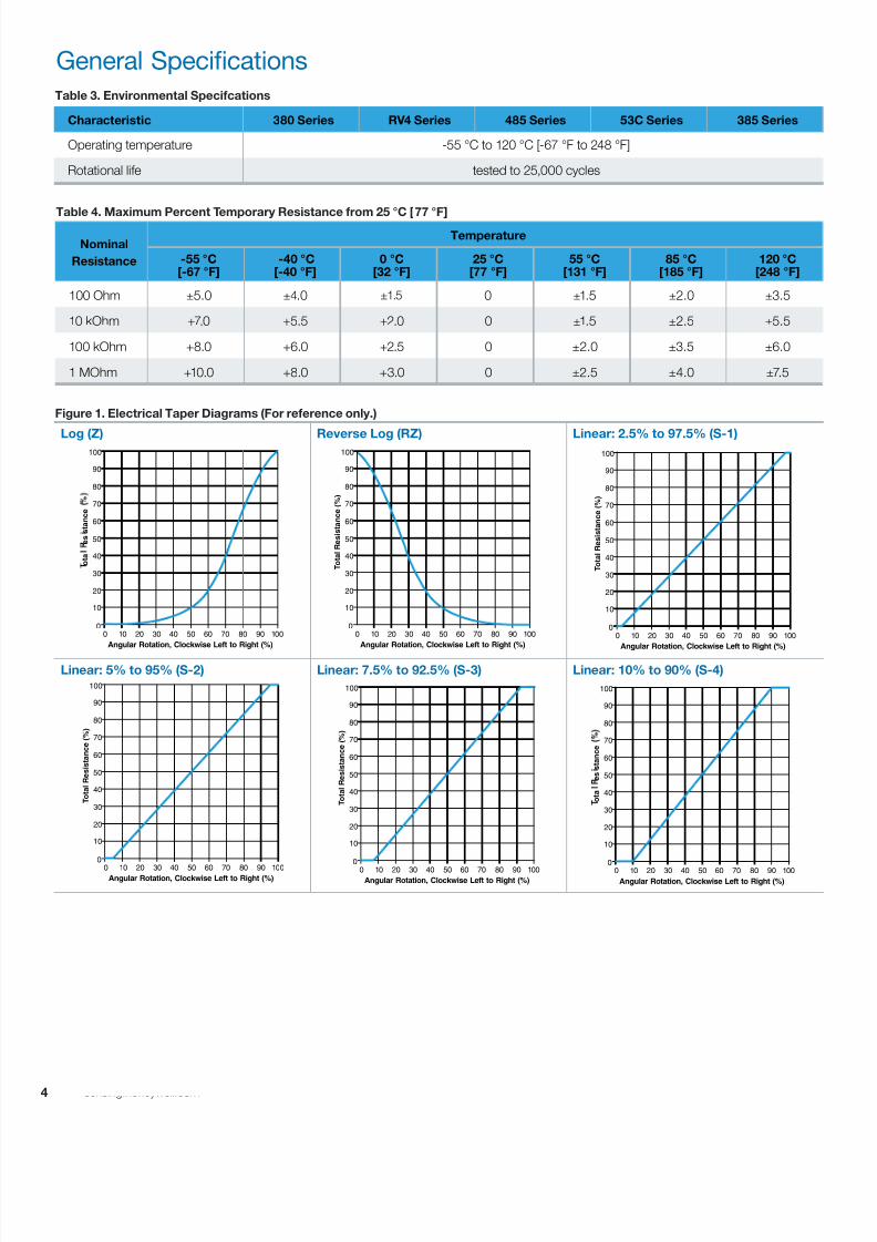
Figure 1. Electrical Taper Diagrams (For reference only.)
Log (Z) Reverse Log (RZ) Linear: 2.5% to 97.5% (S-1)
Linear: 5% to 95% (S-2) Linear: 7.5% to 92.5% (S-3) Linear: 10% to 90% (S-4)
Table 4. Maximum Percent Temporary Resistance from 25 °C [77 °F]
Nominal
Resistance
Temperature
-55 °C[-67 °F]
-40 °C[-40 °F]
0 °C[32 °F]
25 °C[77 °F]
55 °C[131 °F]
85 °C[185 °F]
120 °C[248 °F]
100 Ohm ±5.0 ±4.0 ±1.5 0 ±1.5 ±2.0 ±3.5
10 kOhm +7.0 +5.5 +2.0 0 ±1.5 ±2.5 ±5.5
100 kOhm +8.0 +6.0 +2.5 0 ±2.0 ±3.5 ±6.0
1 MOhm +10.0 +8.0 +3.0 0 ±2.5 ±4.0 ±7.5
Table 3. Environmental Specifcations
Characteristic 380 Series RV4 Series 485 Series 53C Series 385 Series
Operating temperature -55 °C to 120 °C [-67 °F to 248 °F]
Rotational life tested to 25,000 cycles
General Specifications
0 10 20 30 40 50 60 70 80 90 100
0
10
20
30
40
50
60
70
80
90
100
Angular Rotation, Clockwise Left to Right (%)
T o t a l R e s i s t a n c e ( % )
0 10 20 30 40 50 60 70 80 90 100
0
10
20
30
40
50
60
70
80
90
100
Angular Rotation, Clockwise Left to Right (%)
T o t a l R e s i s t a n c e ( % )
0 10 20 30 40 50 60 70 80 90 100
0
10
20
30
40
50
60
70
80
90
100
Angular Rotation, Clockwise Left to Right (%)
o t a
e s s t a n c e
0 10 20 30 40 50 60 70 80 90 100
0
10
20
30
40
50
60
70
80
90
100
Angular Rotation, Clockwise Left to Right (%)
T o t a l R e s i s t a n c e ( % )
0 10 20 30 40 50 60 70 80 90 100
0
10
20
30
40
50
60
70
80
90
100
Angular Rotation, Clockwise Left to Right (%)
o t a
e s s t a n c e
0 10 20 30 40 50 60 70 80 90 100
0
10
20
30
40
50
60
70
80
90
100
Angular Rotation, Clockwise Left to Right (%)
T o t a l R e s i s t a n c e ( % )

7/23/2019 Honeywell Sensing Potentiometers 380 Rv4 485 53c 385 Datasheet 32301266 a En
http://slidepdf.com/reader/full/honeywell-sensing-potentiometers-380-rv4-485-53c-385-datasheet-32301266-a-en 5/47
5sensing.honeywell.com
Figure 1. Electrical Taper Diagrams (continued)
Linear: 15% to 95% (S-5) Linear: 25% to 75% (S-6) Linear: 35% to 65% (S-7)
Linear: 37.5% to 82.5% (S-8) Linear: 42.5% to 57.5% (S-9) Linear: 45% to 55% (S-10)
Linear: 5% to 50%; 50% to 90% (S-11) Linear: 10% to 40%; 57.5% to 82.5% (S-12) Linear: 10% to 45%; 55% to 90% (S-13)
Linear: 35% to 45%; 55% to 65% (S-14) Linear: 45% to 47.5%; 47.5% to 52.5%;52.5% to 55% (S-15)
Linear: 5% to 40%; 45% to 52.5%;60% to 95% (S-16)
General Specifications
0 10 20 30 40 50 60 70 80 90 100
0
10
20
30
40
50
60
70
80
90
100
Angular Rotation, Clockwise Left to Right (%)
T o t a l R e s i s
t a n c e ( % )
0 10 20 30 40 50 60 70 80 90 100
0
10
20
30
40
50
60
70
80
90
100
Angular Rotation, Clockwise Left to Right (%)
T o t a l R e s i s t a n c e ( % )
0 10 20 30 40 50 60 70 80 90 100
0
10
20
30
40
50
60
70
80
90
100
Angular Rotation, Clockwise Left to Right (%)
T o t a l R e s i s
t a n c e ( % )
0 10 20 30 40 50 60 70 80 90 100
0
10
20
30
40
50
60
70
80
90
100
Angular Rotation, Clockwise Left to Right (%)
T o t a l R e s i s t a n c e ( % )
0 10 20 30 40 50 60 70 80 90 100
0
10
20
30
40
50
60
70
80
90
100
Angular Rotation, Clockwise Left to Right (%)
T o t a l R e s i s t a n c e ( % )
0 10 20 30 40 50 60 70 80 90 100
0
10
20
30
40
50
60
70
80
90
100
Angular Rotation, Clockwise Left to Right (%)
T o t a l R e s i s t a n c e ( % )
0 10 20 30 40 50 60 70 80 90 100
0
10
20
30
40
50
60
70
80
90
100
Angular Rotation, Clockwise Left to Right (%)
o t a
e s s t a n c e
0 10 20 30 40 50 60 70 80 90 100
0
10
20
30
40
50
60
70
80
90
100
Angular Rotation, Clockwise Left to Right (%)
o t a
e s s t a n c e
0 10 20 30 40 50 60 70 80 90 100
0
10
20
30
40
50
60
70
80
90
100
Angular Rotation, Clockwise Left to Right (%)
T o t a l R e s i s t a n c e ( % )
0 10 20 30 40 50 60 70 80 90 100
0
10
20
30
40
50
60
70
80
90
100
Angular Rotation, Clockwise Left to Right (%)
T o t a l R e s i s t a n c e ( % )
0 10 20 30 40 50 60 70 80 90 100
0
10
20
30
40
50
60
70
80
90
100
Angular Rotation, Clockwise Left to Right (%)
T o t a l R e s i s t a n c e ( % )
0 10 20 30 40 50 60 70 80 90 100
0
10
20
30
40
50
60
70
80
90
100
Angular Rotation, Clockwise Left to Right (%)
T o t a l R e s i s t a n c e ( % )
7/23/2019 Honeywell Sensing Potentiometers 380 Rv4 485 53c 385 Datasheet 32301266 a En
http://slidepdf.com/reader/full/honeywell-sensing-potentiometers-380-rv4-485-53c-385-datasheet-32301266-a-en 6/47
6 sensing.honeywell.com
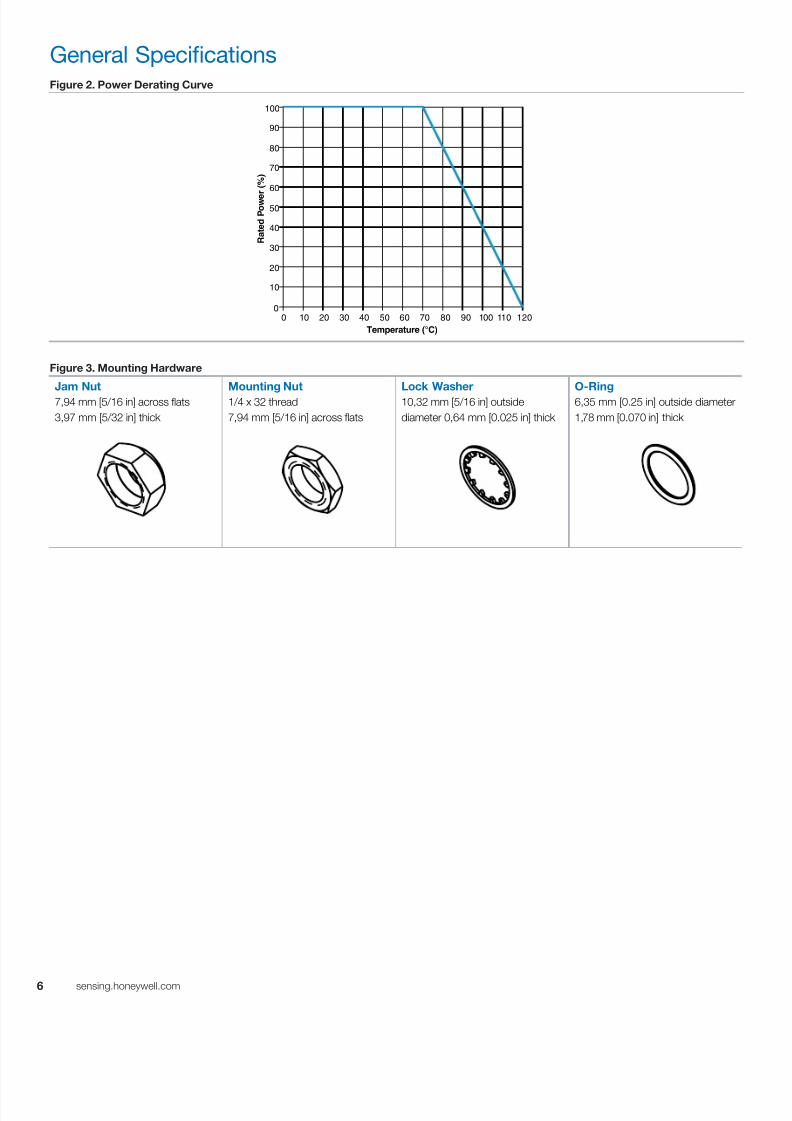
General SpecificationsFigure 2. Power Derating Curve
0 10 20 30 40 50 60 70 80 90 100
0
10
20
30
40
50
60
70
80
90
100
Temperature (°C)
R a t e d P o w e
r ( % )
110 120
Figure 3. Mounting Hardware
Jam Nut
7,94 mm [5/16 in] across flats
3,97 mm [5/32 in] thick
Mounting Nut
1/4 x 32 thread
7,94 mm [5/16 in] across flats
Lock Washer
10,32 mm [5/16 in] outside
diameter 0,64 mm [0.025 in] thick
O-Ring
6,35 mm [0.25 in] outside diameter
1,78 mm [0.070 in] thick

7/23/2019 Honeywell Sensing Potentiometers 380 Rv4 485 53c 385 Datasheet 32301266 a En
http://slidepdf.com/reader/full/honeywell-sensing-potentiometers-380-rv4-485-53c-385-datasheet-32301266-a-en 7/47
7sensing.honeywell.com
General Configuration Guide
380 Series,RV4 Series,485 Series,
53C Series,385 Series
2 W
Conductive
Plastic
Potentiometers
Solder lug with
center tap
Solder lug
Jam nut
Mounting nut
Lock washer
Locating pin
Mounting
hardware
Shaft
BushingTermination
General 380 Series, RV4 Series, 485 Series,
53C Series, 385 Series Terminology
PC pin
Fast-on
Product
Series
Termination
Type
Anti-Rotation
(AR)
Locating Pin
No locating pins
One locating pin:
Two locating pins
Shaft
Length
9,53 mm [0.325]1
12,7 mm [0.50 in]1
15,88 mm [0.625 in]
19,05 mm [0.75 in]
22,23 mm [0.875 in]
31,75 mm [1.25 in]
50,8 mm [2.00 in]
63,5 mm [2.50 in]
Custom
Signifi-
cant
DigitSwitch
Number
of Zeros
that
Follow
Shaft
Type
Round
Flatted
Slotted
Custom
Resistance
Bushing
Type and Length
None3/8-32 NEF-2A:
High Torque:
10 Ohm
15 Ohm
20 Ohm
25 Ohm
50 Ohm
0
1
2
3
4
5
Electrical
Taper
1Applies to 6,25 mm [0.25 in]
bushings only.
ø3,18 mm [0.125 in]:
Straight Knurled
Custom
Custom
2.5% to 97.5%
5% to 95%
7.5% to 92.5%
10% to 90%
15% to 95%
25% to 75%
35% to 65%
37.5% to 82.5%
42.5% to 57.5%
45% to 55%
5% to 50%;50% to 90%
10% to 40%;57.5% to 82.5%
10% to 45%;55% to 90%
10% to 45%;55% to 90%
35% to 45%;55% to 65%;
45% to 57.5%;52.5% to 55%;
5% to 40%;
45% to 52.5%;60% to 95%
Log
Reverse Log
Custom
Linear:
Custom
6,35 mm [0.25 in]
8,69 mm [0.342 in]
9,27 mm [0.365 in]
9,53 mm [0.375 in]
12,7 mm [0.500 in]
7,92 mm [0.312 in]
Standard:
12,7 mm [0.500 in]
3 o’ clock
9 o’ clock
O-ring
Figure 4. General Configuration Guide
This figure shows possible configurations. Not all combinations may be available, please contact Honeywell. See the Order Guides for each series on
subsequent pages for currently available catalog listings.

7/23/2019 Honeywell Sensing Potentiometers 380 Rv4 485 53c 385 Datasheet 32301266 a En
http://slidepdf.com/reader/full/honeywell-sensing-potentiometers-380-rv4-485-53c-385-datasheet-32301266-a-en 8/47
8 sensing.honeywell.com
380 Series Specific Configurations
Table 5. 380 Series Specific Configurations
Shaft
Type
Bushing
Type
AR
Pin
Termin-
ation
Configuration with
Associated Hardware
Shaft
Type
Bushing
Type
AR
Pin
Termin-
ation
Configuration with
Associated Hardware
380-A (See Table 380-A on p. 9.) 380-B (See Table 380-B on p. 10.)
flatted
standard,
9,53 mm
[0.375 in]
1 solder
lug slotted
standard,
9,53 mm
[0.375 in]
2 solder
lug
380-C (See Table 380-C on p. 10.) 380-D (See Table 380-D on p. 11.)
flatted
standard,
9,53 mm
[0.375 in]
1 PC pin round
standard,
9,53 mm
[0.375 in]
1 solder
lug
380-E (See Table 380-E on p. 12.) 380-F (See Table 380-F on p. 13.)
slotted
high
torque,
12,7 mm
[0.500 in]
1 solder
lug slotted
standard,
9,53 mm
[0.375 in]
1 solder
lug
380-G (See Table 380-G on p. 14.) 380-H (See Table 380-H on p. 14.)
slotted
standard,
9,53 mm
[0.375] in
1 solder
lug slotted
standard,
9,53 mm
[0.375] in
1 fast-on
380-I (See Table 380-I on p. 15.)
slotted
standard,
9,53 mm
[0.375] in
2 solder
lug

7/23/2019 Honeywell Sensing Potentiometers 380 Rv4 485 53c 385 Datasheet 32301266 a En
http://slidepdf.com/reader/full/honeywell-sensing-potentiometers-380-rv4-485-53c-385-datasheet-32301266-a-en 9/47
9sensing.honeywell.com
380 Series Order Guides
Table 380-A Order Guide
CatalogListing
Electrical Mechanical Dimensions
R o
H S C o m p
l i a n
t
MountingHardware
R
e s
i s t a n c e
( O h m
)
R e s
i s t a n c e
T o
l e r a n c e
( ± % )
E n d
R e s
i s t a n c e
a t
C W
, M a x .
( O h m
)
E n d
R e s
i s t a n c e
a t C C W
, M a x .
( O h m
)
E f f e c t i v e
E l e c
t r i c a
l
R o t a t i o n ,
T y p .
( D e g r e e
)
E l e c
t r i c
a l R o
t a t i o n , ±
3
( D e g r e e
)
T a p e r
M e c h a
n i c a
l R o
t a t i o n
( D e g r e e
)
O p e r
a t i n g
T o r q u e
( m N m
[ i n - o z
] )
S t
o p
T o r q u e
( N
m
[ i n - l b
] )
S
h a
f t S e a
l
A B C D
F l a t L e n g
t h
( m
m
[ i n ] )
F l a t T
h i c k n e s s
( m
m
[ i n ] )
S h a f t L e n g
t h
( m
m
[ i n ] )
B u s h
i n g
L e n g
t h
( m
m
[ i n ] )
380000M8629 1 k 10 4 4 274 312 S-4 312 1-4[7-28]
12[1.4]
no 7,95
[0.313]5,54
[0.218]19,46[0.766]
9,53[0.375]
yes unassembled
380000M8630 2.5 k 10 4 4 274 312 S-4 312 1-4[7-28]
12[1.4]
no 7,95
[0.313]5,54
[0.218]19,46[0.766]
9,53[0.375]
yes unassembled
380000M8643 1 k 10 4 4 274 312 S-4 312 1-4[7-28]
12[1.4]
no 14,30
[0.563]5,54
[0.218]25,4
[1.000]9,53
[0.375] yes unassembled
380000M8682 50 k 10 4 4 274 312 S-4 312 1-4[7-28]
12[1.4]
no 7,95
[0.313]5,54
[0.218]19,46[0.766]
9,53[0.375]
yes unassembled
380017M00071,2 500 10 4 4 274 312 S-4 312 6[7-42]
12[1.4]
yes 7,95[0.313]
5,54[0.218]
22,23[0.875]
9,53[0.375]
no unassembled
380017M8606 10 k 10 4 4 274 312 S-4 312
6
[7-42]
12
[1.4] yes
7,95
[0.313]
5,54
[0.218]
19,05
[0.750]
9,53
[0.375] yes unassembled
380017M87681 25 k 10 4 4 274 312 S-4 312 6[7-42]
12[1.4]
yes 7,95[0.313]
5,54[0.218]
19,05[0.750]
9,53[0.375]
yes unassembled
380017M95501 5 k 10 4 4 274 312 S-4 312 6[7-42]
12[1.4]
yes 7,95[0.313]
5,54[0.218]
19,05[0.750]
9,53[0.375]
yes unassembled
Dimensional Drawings (For reference only: mm [in].)
1Supplied with nickel-plated, phosphor bronze lock washer.2Supplied with two mounting nuts.
1Left 2
Center
3Right
Shown with 50% shaft rotation
Mounting surface
3/8-32 NEF-2A
ø27,79 Max. [1.094]
13,49[0.531]
90°
12,87[0.546]
22,25 Max.[0.875]
3,18 Min.[0.125]
A
B
D
C14,30[0.563]
3,18[0.125]
ø6,35 [0.250]
2,77[0.109]
2X 20°
3X 1,57 [0.062]
3X 2,36 [0.093]
3X 1,57 [0.062]
3X 3,15 [0.124]
0,635[0.025]
Locatingpin
Terminal base
7/23/2019 Honeywell Sensing Potentiometers 380 Rv4 485 53c 385 Datasheet 32301266 a En
http://slidepdf.com/reader/full/honeywell-sensing-potentiometers-380-rv4-485-53c-385-datasheet-32301266-a-en 10/47
10 sensing.honeywell.com
380 Series Order Guides
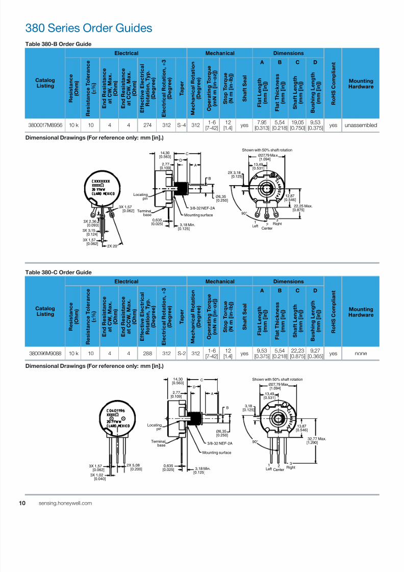
Table 380-B Order Guide
CatalogListing
Electrical Mechanical Dimensions
R o
H S C o m p
l i a n
t
MountingHardware
R
e s
i s t a n c e
( O h m
)
R e s
i s t a n c e
T o
l e r a n c e
( ± % )
E n d
R e s
i s t a n c e
a t
C W
, M a x .
( O h m
)
E n d
R e s
i s t a n c e
a t C C W
, M a x .
( O h m
)
E f f e c t i v e
E l e c
t r i c a
l
R o t a t i o n ,
T y p .
( D e g r e e
)
E l e c
t r i c
a l R o
t a t i o n , ±
3
( D e g r e e
)
T a p e r
M e c h a
n i c a
l R o
t a t i o n
( D e g r e e
)
O p e r
a t i n g
T o r q u e
( m N m
[ i n - o z
] )
S t
o p
T o r q u e
( N
m
[ i n - l b
] )
S
h a
f t S e a
l
A B C D
F l a t L e n g
t h
( m
m
[ i n ] )
F l a t T
h i c k n e s s
( m
m
[ i n ] )
S h a f t L e n g
t h
( m
m
[ i n ] )
B u s h
i n g
L e n g
t h
( m
m
[ i n ] )
3800017M8956 10 k 10 4 4 274 312 S-4 312 1-6[7-42]
12[1.4]
yes 7.95[0.313]
5,54[0.218]
19,05[0.750]
9,53[0.375]
yes unassembled
Dimensional Drawings (For reference only: mm [in].)
Table 380-C Order Guide
CatalogListing
Electrical Mechanical Dimensions
R o
H S C o m p l
i a n
t
MountingHardware
R e s
i s t a n c e
( O h m
)
R e s
i s t a n c e
T o
l e r a
n c e
( ± % )
E n
d R e s
i s t a n c e
a t C W
, M a x .
( O h m
)
E n
d R e s
i s t a n c e
a t C C W
, M a x .
( O h m
)
E f f e c
t i v e
E l e c
t r i c a
l
R o
t a t i o n ,
T y p .
( D e g r e e
)
E l e c
t r i c a
l R o
t a t i o n , ±
3
( D e g r e e
)
T a p e r
M e c
h a n
i c a
l R o
t a t i o n
( D e g r e e
)
O p e r a
t i n g
T o r q u e
( m N m
[ i n - o z ]
)
S t o p
T o r q u e
( N m
[ i n - l b
] )
S h a
f t S e a l
A B C D
F l a t L e n g
t h
( m m
[ i n ] )
F l a t T h i c k n e s s
( m m
[ i n ] )
S h a
f t L e n g
t h
( m m
[ i n ] )
B u s
h i n g
L e n g
t h
( m m
[ i n ] )
380096M9088 10 k 10 4 4 288 312 S-2 312 1-6[7-42]
12[1.4]
yes 9,53[0.375]
5,54[0.218]
22,23[0.875]
9,27[0.365]
yes none
Dimensional Drawings (For reference only: mm [in].)
Shown with 50% shaft rotation
ø27,79 Max. [1.094]
13,49[0.531]
2X 3,18 [0.125]
90°Mounting surface
3/8-32 NEF-2A
3,18 Min.[0.125]
ø6,35
[0.250]
A
B
D
C14,30[0.563]
2X 20°
3X 1,57 [0.062]
3X 2,36 [0.093]
3X 1,57 [0.062]
3X 3,15 [0.124]
1Left 2
Center
3Right
12,87
[0.546] 22,25 Max.
[0.875]
0,635[0.025]
2,77[0.109]
Locating
pin
Terminal base
Shown with 50% shaft rotation
Mounting surface
3/8-32 NEF-2A
1Left
2Center
3Right3X 1,57
[0.062] 3,18 Min.[0.125]
0,635[0.025]
ø6,35 [0.250]
A
B
C
D
3,18[0.125]
90°
14,30[0.563]
2,77[0.109]
ø27,79 Max. [1.094]
13,49[0.531]
13,87[0.546]
32,77 Max.[1.290]
3X 1,02 [0.040]
2X 5,08 [0.200]
Locatingpin
Terminal base
7/23/2019 Honeywell Sensing Potentiometers 380 Rv4 485 53c 385 Datasheet 32301266 a En
http://slidepdf.com/reader/full/honeywell-sensing-potentiometers-380-rv4-485-53c-385-datasheet-32301266-a-en 11/47
1sensing.honeywell.com
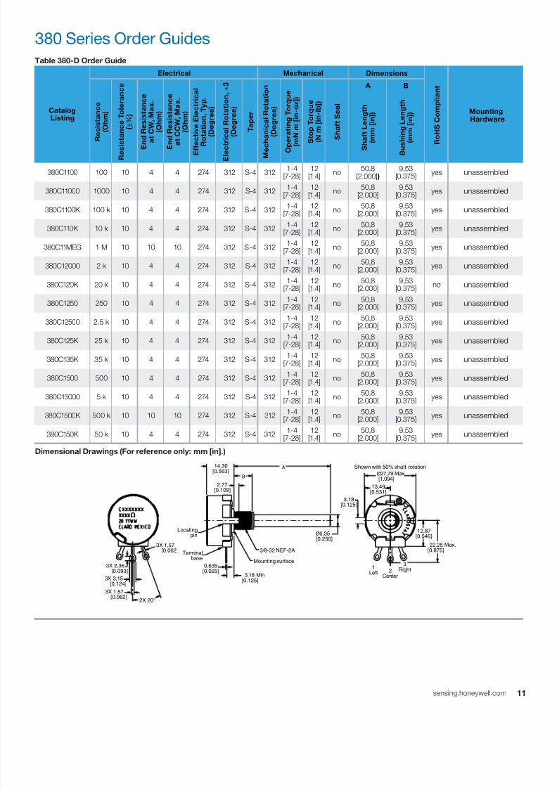
Table 380-D Order Guide
CatalogListing
Electrical Mechanical Dimensions
R o
H S C o m p
l i a n
t
Mounting Hardware
R
e s
i s t a n c e
( O h m
)
R e s
i s t a n c e
T o
l e r a n c e
( ± % )
E n d
R e s
i s t a n c e
a t
C W
, M a x .
( O h m
)
E n d
R e s
i s t a n c e
a t C C W
, M a x .
( O h m
)
E f f e c t i v e
E l e c
t r i c a
l
R o t a t i o n ,
T y p .
( D e g r e e
)
E l e c
t r i c a
l R o
t a t i o n , ±
3
( D e g r e e
)
T a p e r
M e c h a
n i c a
l R o
t a t i o n
( D e g r e e
)
O p e r
a t i n g
T o r q u e
( m N m
[ i n - o z
] )
S t
o p
T o r q u e
( N
m [ i n - l b
] )
S
h a
f t S e a
l
A B
S h a f t L e n g
t h
( m
m
[ i n ] )
B u s h
i n g
L e n g
t h
( m
m
[ i n ] )
380C1100 100 10 4 4 274 312 S-4 312 1-4[7-28]
12[1.4]
no 50,8
[2.000] )9,53
[0.375] yes unassembled
380C11000 1000 10 4 4 274 312 S-4 312 1-4[7-28]
12[1.4]
no 50,8
[2.000]9,53
[0.375] yes unassembled
380C1100K 100 k 10 4 4 274 312 S-4 312 1-4[7-28]
12[1.4]
no 50,8
[2.000]9,53
[0.375] yes unassembled
380C110K 10 k 10 4 4 274 312 S-4 312 1-4[7-28]
12[1.4]
no 50,8
[2.000]9,53
[0.375] yes unassembled
380C11MEG 1 M 10 10 10 274 312 S-4 312 1-4[7-28]
12[1.4]
no 50,8
[2.000]9,53
[0.375] yes unassembled
380C12000 2 k 10 4 4 274 312 S-4 312 1-4[7-28]
12[1.4]
no 50,8
[2.000]9,53
[0.375] yes unassembled
380C120K 20 k 10 4 4 274 312 S-4 312 1-4[7-28]
12[1.4]
no 50,8
[2.000]9,53
[0.375] no unassembled
380C1250 250 10 4 4 274 312 S-4 312 1-4[7-28]
12[1.4]
no 50,8
[2.000]9,53
[0.375] yes unassembled
380C12500 2.5 k 10 4 4 274 312 S-4 312 1-4[7-28]
12[1.4]
no 50,8
[2.000]9,53
[0.375] yes unassembled
380C125K 25 k 10 4 4 274 312 S-4 312 1-4[7-28]
12[1.4]
no 50,8
[2.000]9,53
[0.375] yes unassembled
380C135K 35 k 10 4 4 274 312 S-4 312 1-4[7-28]
12[1.4]
no 50,8
[2.000]9,53
[0.375] yes unassembled
380C1500 500 10 4 4 274 312 S-4 312 1-4[7-28]
12[1.4]
no 50,8
[2.000]9,53
[0.375] yes unassembled
380C15000 5 k 10 4 4 274 312 S-4 312 1-4[7-28]
12[1.4]
no 50,8
[2.000]9,53
[0.375] yes unassembled
380C1500K 500 k 10 10 10 274 312 S-4 312 1-4[7-28] 12[1.4] no 50,8[2.000] 9,53[0.375] yes unassembled
380C150K 50 k 10 4 4 274 312 S-4 312 1-4[7-28]
12[1.4]
no 50,8
[2.000]9,53
[0.375] yes unassembled
Dimensional Drawings (For reference only: mm [in].)
380 Series Order Guides
Shown with 50% shaft rotation
Mounting surface
3/8-32 NEF-2A
2X 20°
3X 1,57
[0.062]
3X 2,36 [0.093]
3X 1,57 [0.062]
3X 3,15 [0.124]
1Left 2
Center
3Right
12,87[0.546]
22,25 Max.
[0.875]
3,18 Min.[0.125]
0,635[0.025]
ø6,35 [0.250]
A
B
3,18[0.125]
2,77[0.109]
14,30[0.563]
ø27,79 Max. [1.094]
13,49[0.531]
Locatingpin
Terminal base
7/23/2019 Honeywell Sensing Potentiometers 380 Rv4 485 53c 385 Datasheet 32301266 a En
http://slidepdf.com/reader/full/honeywell-sensing-potentiometers-380-rv4-485-53c-385-datasheet-32301266-a-en 12/47
12 sensing.honeywell.com
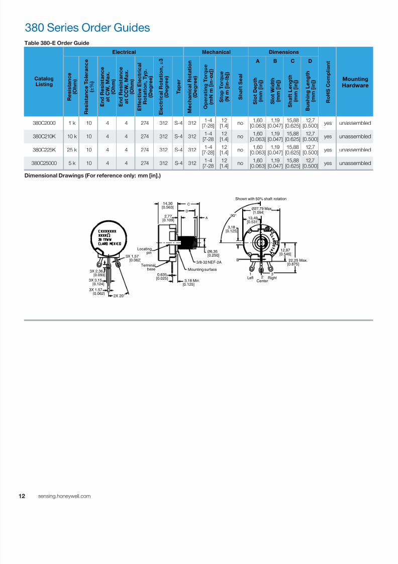
Table 380-E Order Guide
CatalogListing
Electrical Mechanical Dimensions
R o
H S C o m p
l i a n
t
MountingHardware
R
e s
i s t a n c e
( O h m
)
R e s
i s t a n c e
T o
l e r a n c e
( ± % )
E n d
R e s
i s t a n c e
a t
C W
, M a x .
( O h m
)
E n d
R e s
i s t a n c e
a t
C C W
, M a x .
( O h m
)
E f f e c
t i v e
E l e c
t r i c a
l
R o
t a t i o n ,
T y p .
( D e g r e e
)
E l e c
t r i c a
l R o
t a t i o n , ±
3
( D e g r e e
)
T a p e r
M e c h a
n i c a
l R o
t a t i o n
( D e g r e e
)
O p e r a
t i n g
T o r q u e
( m N m
[ i n - o z
] )
S t
o p
T o r q u e
( N
m
[ i n - l b
] )
S
h a
f t S e a
l
A B C D
S l o
t D e p
t h
( m
m
[ i n ] )
S l o
t W i d t h
( m
m
[ i n ] )
S h a f t L e n g
t h
( m
m
[ i n ] )
B u s h
i n g
L e n g
t h
( m
m
[ i n ] )
380C2000 1 k 10 4 4 274 312 S-4 312 1-4[7-28]
12[1.4]
no 1,60[0.063]
1,19[0.047]
15,88[0.625]
12,7[0.500]
yes unassembled
380C210K 10 k 10 4 4 274 312 S-4 312 1-4
[7-2812
[1.4] no
1,60[0.063]
1,19[0.047]
15,88[0.625]
12,7[0.500]
yes unassembled
380C225K 25 k 10 4 4 274 312 S-4 312 1-4[7-28]
12[1.4]
no 1,60[0.063]
1,19[0.047]
15,88[0.625]
12,7[0.500]
yes unassembled
380C25000 5 k 10 4 4 274 312 S-4 312 1-4
[7-2812
[1.4] no
1,60[0.063]
1,19[0.047]
15,88[0.625]
12,7[0.500]
yes unassembled
Dimensional Drawings (For reference only: mm [in].)
380 Series Order Guides
Shown with 50% shaft rotation
Mounting surface
3/8-32 NEF-2AB
2X 20°
3X 1,57 [0.062]
3X 2,36 [0.093]
3X 1,57 [0.062]
3X 3,15 [0.124]
1Left 2
Center
3Right
12,87[0.546]
22,25 Max.[0.875]
3,18 Min.[0.125]
0,635[0.025]
ø6,35 [0.250]
A
C
D
90°
3,18[0.125]
14,30[0.563]
2,77[0.109]
ø27,79 Max. [1.094]
13,49[0.531]
Locatingpin
Terminal base

7/23/2019 Honeywell Sensing Potentiometers 380 Rv4 485 53c 385 Datasheet 32301266 a En
http://slidepdf.com/reader/full/honeywell-sensing-potentiometers-380-rv4-485-53c-385-datasheet-32301266-a-en 13/47
1sensing.honeywell.com
Table 380-F Order Guide
CatalogListing
Electrical Mechanical Dimensions
R o
H S C o m p
l i a n
t
MountingHardware
R
e s
i s t a n c e
( O h m
)
R e s
i s t a n c e
T o
l e r a n c e
( ± % )
E n d
R e s
i s t a n c e
a t
C W
, M a x .
( O h m
)
E n d
R e s
i s t a n c e
a t C C W
, M a x .
( O h m
)
E f f e c t i v e
E l e c
t r i c a
l
R o t a t i o n ,
T y p .
( D e g r e e
)
E l e c
t r i c
a l R o
t a t i o n , ±
3
( D e g r e e
)
T a p e r
M e c h a
n i c a
l R o
t a t i o n
( D e g r e e
)
O p e r
a t i n g
T o r q u e
( m N m
[ i n - o z
] )
S t
o p
T o r q u e
( N
m
[ i n - l b
] )
S
h a
f t S e a
l
A B C D
S l o t L e n g
t h
( m
m
[ i n ] )
S l o
t W i d t h
( m
m
[ i n ] )
S h a f t L e n g
t h
( m
m
[ i n ] )
B u s h
i n g
L e n g
t h
( m
m
[ i n ] )
380C3100 100 10 4 4 274 312 S-4 312 1-4[7-28]
12[1.4]
no 1,60[0.063]
1,19[0.047]
22,23[0.875]
9,53[0.375]
yes unassembled
380C31000 1 k 10 4 4 274 312 S-4 312 1-4[7-28]
12[1.4]
no 1,60[0.063]
1,19[0.047]
22,23[0.875]
9,53[0.375]
yes unassembled
380C3100K 100 k 10 4 4 274 312 S-4 312 1-4[7-28]
12[1.4]
no 1,60[0.063]
1,19[0.047]
22,23[0.875]
9,53[0.375]
yes unassembled
380C310K 10 k 10 4 4 274 312 S-4 312 1-4[7-28]
12[1.4]
no 1,60[0.063]
1,19[0.047]
22,23[0.875]
9,53[0.375]
yes unassembled
380C31MEG 1 M 10 10 10 274 312 S-4 312 1-4[7-28]
12[1.4]
no 1,60[0.063]
1,19[0.047]
22,23[0.875]
9,53[0.375]
yes unassembled
380C32000 2 k 10 4 4 274 312 S-4 312 1-4[7-28]
12[1.4]
no 1,60[0.063]
1,19[0.047]
22,23[0.875]
9,53[0.375]
yes unassembled
380C3200K 200 k 10 4 4 274 312 S-4 312 1-4[7-28]
12[1.4]
no 1,60[0.063]
1,19[0.047]
22,23[0.875]
9,53[0.375]
no unassembled
380C3250 250 10 4 4 274 312 S-4 312 1-4[7-28]
12[1.4]
no 1,60[0.063]
1,19[0.047]
22,23[0.875]
9,53[0.375]
no unassembled
380C32500 2.5 k 10 4 4 274 312 S-4 312 1-4[7-28]
12[1.4]
no 1,60[0.063]
1,19[0.047]
22,23[0.875]
9,53[0.375]
yes unassembled
380C3250K 250 k 10 10 10 274 312 S-4 312 1-4[7-28]
12[1.4]
no 1,60[0.063]
1,19[0.047]
22,23[0.875]
9,53[0.375]
yes unassembled
380C325K 25 k 10 4 4 274 312 S-4 312 1-4[7-28]
12[1.4]
no 1,60[0.063]
1,19[0.047]
22,23[0.875]
9,53[0.375]
yes unassembled
380C3500 500 10 4 4 274 312 S-4 312 1-4[7-28]
12[1.4]
no 1,60[0.063]
1,19[0.047]
22,23[0.875]
9,53[0.375]
yes unassembled
380C35000 5 k 10 4 4 274 312 S-4 312 1-4[7-28]
12[1.4]
no 1,60[0.063]
1,19[0.047]
22,23[0.875]
9,53[0.375]
yes unassembled
380C3500K 500 k 10 10 10 274 312 S-4 312 1-4[7-28] 12[1.4] no 1,60[0.063] 1,19[0.047] 22,23[0.875] 9,53[0.375] yes unassembled
380C350K 50 k 10 4 4 274 312 S-4 312 1-4[7-28]
12[1.4]
no 1,60[0.063]
1,19[0.047]
22,23[0.875]
9,53[0.375]
yes unassembled
Dimensional Drawings (For reference only: mm [in].)
380 Series Order Guides
Shown with 50% shaft rotation
Mounting surface
3/8-32 NEF-2A
3,18 Min.[0.125]
ø27,79 [0.250]
A
B
D
C14,30[0.563]
2X 20°
3X 1,57 [0.062]
3X 2,36 [0.093]
3X 1,57 [0.062]
3X 3,15 [0.124]
1Left 2
Center
3Right
12,87[0.546]
22,25 Max.[0.875]
3,18[0.125]
90°
0,635[0.025]
ø27,79 Max. [1.094]
13,49[0.531]
Locatingpin
Terminal base
7/23/2019 Honeywell Sensing Potentiometers 380 Rv4 485 53c 385 Datasheet 32301266 a En
http://slidepdf.com/reader/full/honeywell-sensing-potentiometers-380-rv4-485-53c-385-datasheet-32301266-a-en 14/47
14 sensing.honeywell.com
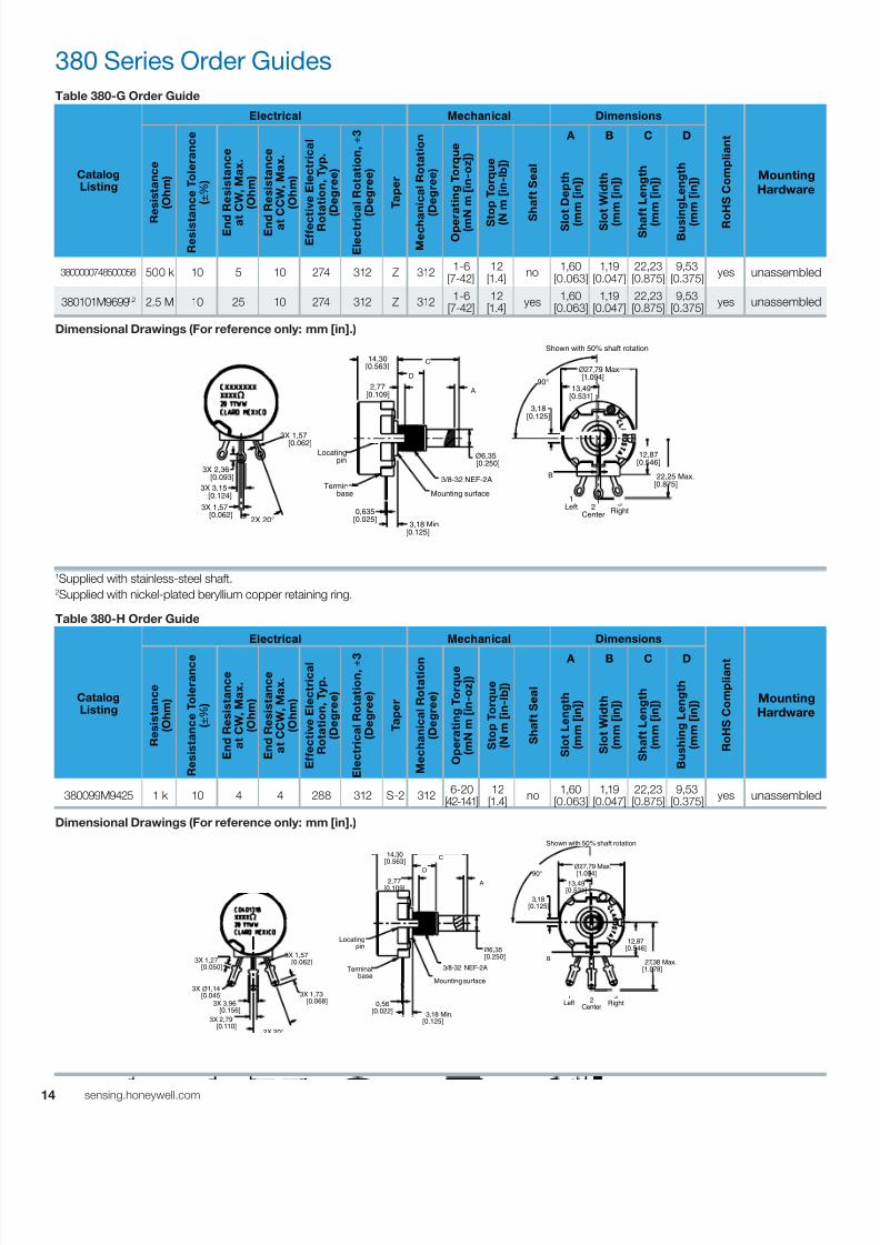
Table 380-G Order Guide
CatalogListing
Electrical Mechanical Dimensions
R o
H S C o m p
l i a n
t
Mounting
Hardware
R
e s
i s t a n c e
( O h m
)
R e s
i s t a n c e
T o
l e r a n c e
( ± % )
E n d
R e s
i s t a n c e
a t
C W
, M a x .
( O h m
)
E n d
R e s
i s t a n c e
a t C C W
, M a x .
( O h m
)
E f f e c t i v e
E l e c
t r i c a
l
R o t a t i o n ,
T y p .
( D e g r e e
)
E l e c
t r i c
a l R o
t a t i o n , ±
3
( D e g r e e
)
T a p e r
M e c h a
n i c a
l R o
t a t i o n
( D e g r e e
)
O p e r
a t i n g
T o r q u e
( m N m
[ i n - o z
] )
S t
o p
T o r q u e
( N
m
[ i n - l b
] )
S
h a
f t S e a
l
A B C D
S l o
t D e p
t h
( m
m
[ i n ] )
S l o
t W i d t h
( m
m
[ i n ] )
S h a f t L e n g
t h
( m
m
[ i n ] )
B u s i n g
L e n g
t h
( m
m
[ i n ] )
3800000748500058 500 k 10 5 10 274 312 Z 312 1-6[7-42]
12[1.4]
no 1,60[0.063]
1,19[0.047]
22,23[0.875]
9,53[0.375]
yes unassembled
380101M96991,2 2.5 M 10 25 10 274 312 Z 312 1-6[7-42]
12[1.4]
yes 1,60[0.063]
1,19[0.047]
22,23[0.875]
9,53[0.375]
yes unassembled
Dimensional Drawings (For reference only: mm [in].)
1Supplied with stainless-steel shaft.2Supplied with nickel-plated beryllium copper retaining ring.
Table 380-H Order Guide
CatalogListing
Electrical Mechanical Dimensions
R o
H S C o m p
l i a n t
MountingHardware
R e s
i s t a n c e
( O h m
)
R e s
i s t a n c e
T o
l e r a n c e
( ± % )
E n
d R e s
i s t a n c e
a t C W
, M a x .
( O h m
)
E n
d R e s
i s t a n c e
a t C C W
, M a x .
( O h m
)
E f f e c
t i v e
E l e c
t r i c a
l
R o
t a t i o n ,
T y p .
( D e g r e e
)
E l e c
t r i c a
l R o
t a t i o n , ± 3
( D e g r e e
)
T a p e r
M e c
h a n
i c a
l R o
t a t i o n
( D e g r e e
)
O p e r a
t i n g
T o r q u e
( m N m
[ i n - o z
] )
S t o p
T o r q u e
( N m
[ i n - l b
] )
S h a
f t S e a
l
A B C D
S l o t L e n g
t h
( m m
[ i n ] )
S l o t W i d t h
( m m
[ i n ] )
S h a
f t L e n g
t h
( m m
[ i n ] )
B u s
h i n g
L e n g
t h
( m m
[ i n ] )
380099M9425 1 k 10 4 4 288 312 S-2 312 6-20[42-141]
12[1.4]
no 1,60[0.063]
1,19[0.047]
22,23[0.875]
9,53[0.375]
yes unassembled
Dimensional Drawings (For reference only: mm [in].)
380 Series Order Guides
Shown with 50% shaft rotation
Mounting surface
3/8-32 NEF-2A
2X 20°
3X 1,57 [0.062]
3X 2,36 [0.093]
3X 1,57 [0.062]
3X 3,15 [0.124] 1
Left 2Center
3Right
12,87[0.546]
22,25 Max.[0.875]
3,18[0.125]
A
B
C
D
3,18 Min.[0.125]
0,635[0.025]
14,30[0.563]
2,77[0.109]
ø6,35 [0.250]
90°
ø27,79 Max. [1.094]
13,49[0.531]
Locatingpin
Terminal base
Shown with 50% shaft rotation
Mounting surface
3/8-32 NEF-2A
3,18[0.125]
A
B
C
D 90°
3,18 Min.[0.125]
14,30[0.563]
2,77[0.109]
ø6,35 [0.250]
ø27,79 Max.
[1.094]13,49
[0.531]
2X 20°
3X 1,57 [0.062]
3X 2,79 [0.110]
3X 3,96 [0.156]
3X 1,73 [0.068]
3X 1,27 [0.050]
3X ø1,14 [0.045]
0,56[0.022]
Locatingpin
Terminal base
1Left 2
Center
3Right
12,87[0.546]
27,38 Max.[1.078]
7/23/2019 Honeywell Sensing Potentiometers 380 Rv4 485 53c 385 Datasheet 32301266 a En
http://slidepdf.com/reader/full/honeywell-sensing-potentiometers-380-rv4-485-53c-385-datasheet-32301266-a-en 15/47
1sensing.honeywell.com
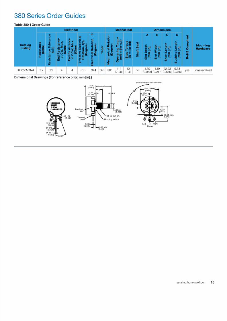
Table 380-I Order Guide
CatalogListing
Electrical Mechanical Dimensions
R o
H S C o m p
l i a n
t
MountingHardware
R
e s
i s t a n c e
( O h m
)
R e s
i s t a n c e
T o
l e r a n c e
( ± % )
E n d
R e s
i s t a n c e
a t
C W
, M a x .
( O h m
)
E n d
R e s
i s t a n c e
a t C C W
, M a x .
( O h m
)
E f f e c t i v e
E l e c
t r i c a
l
R o t a t i o n ,
T y p .
( D e g r e e
)
E l e c
t r i c
a l R o
t a t i o n , ±
3
( D e g r e e
)
T a p e r
M e c h a
n i c a
l R o
t a t i o n
( D e g r e e
)
O p e r
a t i n g
T o r q u e
( m N m
[ i n - o z
] )
S t
o p
T o r q u e
( N
m
[ i n - l b
] )
S
h a
f t S e a
l
A B C D
S l o
t D e p
t h
( m
m
[ i n ] )
S l o
t W i d t h
( m
m
[ i n ] )
S h a f t L e n g
t h
( m
m
[ i n ] )
B u s h
i n g
L e n g
t h
( m
m
[ i n ] )
380036M7444 1 k 10 4 4 310 344 S-3 360 1-4[7-28]
12[1.4]
no 1,60[0.063]
1,19[0.047]
22,23[0.875]
9,53[0.375]
yes unassembled
Dimensional Drawings (For reference only: mm [in].)
380 Series Order Guides
A
B
C
D
Shown with 50% shaft rotation
Mounting surface
3/8-32 NEF-2A
2X 20°
3X 1,57 [0.062]
3X 2,36 [0.093]
3X 1,57 [0.062]
3X 3,15 [0.124]
1Left 2
Center
3Right
12,87
[0.546] 22,25 Max.
[0.875]
ø6,35
[0.250]
3,18[0.125]
90°
3,18 Min.[0.125]
0,635[0.025]
14,30[0.563]
2,77[0.109]
ø27,79 Max. [1.094]
13,49[0.531]
Locatingpin
Terminal base

7/23/2019 Honeywell Sensing Potentiometers 380 Rv4 485 53c 385 Datasheet 32301266 a En
http://slidepdf.com/reader/full/honeywell-sensing-potentiometers-380-rv4-485-53c-385-datasheet-32301266-a-en 16/47
16 sensing.honeywell.com
RV4 Series Specific Configurations
Table 6. RV4 Series Specific Configurations
Shaft
Type
Bushing
Type
AR
Pin
Termin-
ation
Configuration with
Associated Hardware
Shaft
Type
Bushing
Type
AR
Pin
Termin-
ation
Configuration with
Associated Hardware
RV4-A (See Table RV4-A on p. 17.) RV4-B (See Table RV4-B on p. 18.)
slotted
high
torque,
12,7 mm
[0.500 in]
1solder
lugslotted
standard,
9,53 mm
[0.375 in]
1solder
lug
7/23/2019 Honeywell Sensing Potentiometers 380 Rv4 485 53c 385 Datasheet 32301266 a En
http://slidepdf.com/reader/full/honeywell-sensing-potentiometers-380-rv4-485-53c-385-datasheet-32301266-a-en 17/47
1sensing.honeywell.com
RV4 Series Order Guides
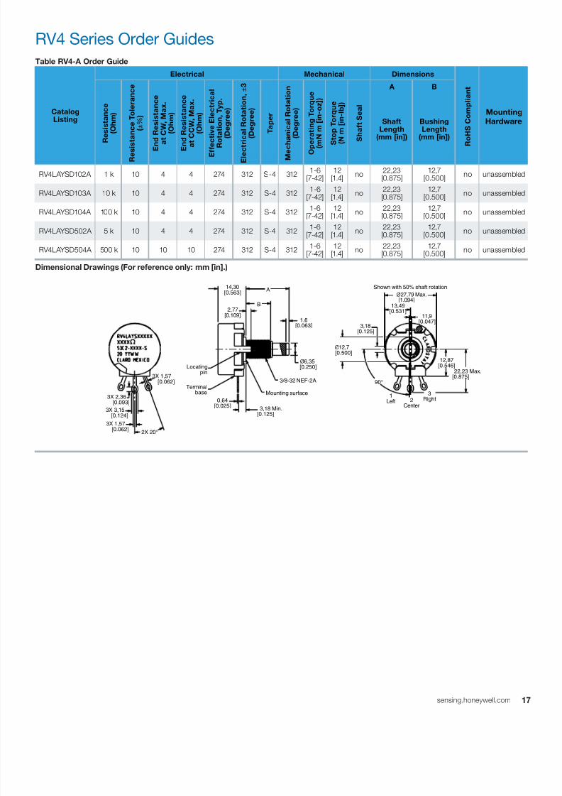
Table RV4-A Order Guide
CatalogListing
Electrical Mechanical Dimensions
R o
H S C o m p
l i a n
t
Mounting
Hardware
R
e s
i s t a n c e
( O h m
)
R e s
i s t a n c e
T o
l e r a n c e
( ± % )
E n d
R e s
i s t a n c e
a t
C W
, M a x .
( O h m
)
E n d
R e s
i s t a n c e
a t C C W
, M a x .
( O h m
)
E f f e c t i v e
E l e c
t r i c a
l
R o t a t i o n ,
T y p .
( D e g r e e
)
E l e c
t r i c
a l R o
t a t i o n , ±
3
( D e g r e e
)
T a p e r
M e c h a
n i c a
l R o
t a t i o n
( D e g r e e
)
O p e r
a t i n g
T o r q u e
( m N m
[ i n - o z
] )
S t
o p
T o r q u e
( N
m
[ i n - l b
] )
S
h a
f t S e a
l
A B
ShaftLength
(mm [in])
BushingLength
(mm [in])
RV4LAYSD102A 1 k 10 4 4 274 312 S-4 312 1-6[7-42]
12[1.4]
no 22,23
[0.875]12,7
[0.500] no unassembled
RV4LAYSD103A 10 k 10 4 4 274 312 S-4 312 1-6[7-42]
12[1.4]
no 22,23
[0.875]12,7
[0.500] no unassembled
RV4LAYSD104A 100 k 10 4 4 274 312 S-4 312 1-6[7-42]
12[1.4]
no 22,23
[0.875]12,7
[0.500] no unassembled
RV4LAYSD502A 5 k 10 4 4 274 312 S-4 312 1-6[7-42]
12[1.4]
no 22,23
[0.875]12,7
[0.500] no unassembled
RV4LAYSD504A 500 k 10 10 10 274 312 S-4 312 1-6[7-42]
12[1.4]
no 22,23
[0.875]12,7
[0.500] no unassembled
Dimensional Drawings (For reference only: mm [in].)
90°
2X 20°
3X 1,57 [0.062]
3X 2,36 [0.093]
3X 1,57 [0.062]
3X 3,15
[0.124]
3,18 Min.[0.125]
0,64[0.025]
ø6,35 [0.250]
Mounting surface
3/8-32 NEF-2A
Locating pin
Terminal base
14,30[0.563]
A
B
1,6[0.063]
2,77[0.109]
1Left 2
Center
3Right
12,87[0.546] 22,23 Max.
[0.875]
Shown with 50% shaft rotation
ø27,79 Max. [1.094]
3,18[0.125]
13,49[0.531]
ø12,7 [0.500]
11,9[0.047]
7/23/2019 Honeywell Sensing Potentiometers 380 Rv4 485 53c 385 Datasheet 32301266 a En
http://slidepdf.com/reader/full/honeywell-sensing-potentiometers-380-rv4-485-53c-385-datasheet-32301266-a-en 18/47
18 sensing.honeywell.com
RV4 Series Order Guides
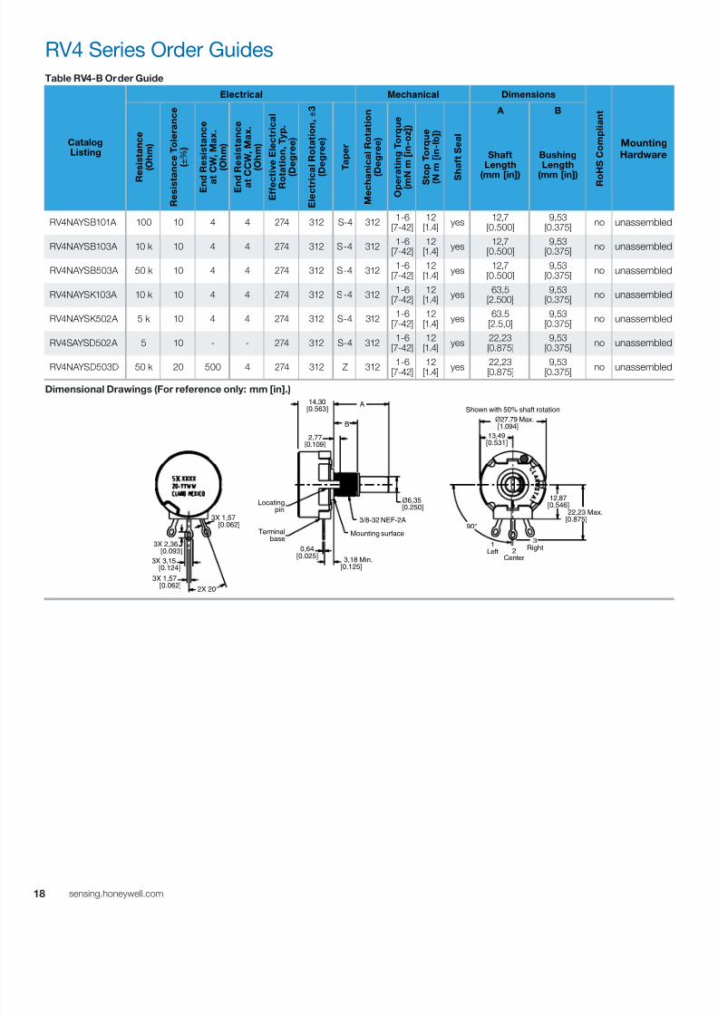
Table RV4-B Order Guide
CatalogListing
Electrical Mechanical Dimensions
R o
H S C o m p
l i a n
t
Mounting
Hardware
R
e s
i s t a n c e
( O h m
)
R e s
i s t a n c e
T o
l e r a n c e
( ± % )
E n d
R e s
i s t a n c e
a t
C W
, M a x .
( O h m
)
E n d
R e s
i s t a n c e
a t C C W
, M a x .
( O h m
)
E f f e c t i v e
E l e c
t r i c a
l
R o t a t i o n ,
T y p .
( D e g r e e
)
E l e c
t r i c
a l R o
t a t i o n , ±
3
( D e g r e e
)
T a p e r
M e c h a
n i c a
l R o
t a t i o n
( D e g r e e
)
O p e r
a t i n g
T o r q u e
( m N m
[ i n - o z
] )
S t
o p
T o r q u e
( N
m
[ i n - l b
] )
S
h a
f t S e a
l
A B
ShaftLength
(mm [in])
BushingLength
(mm [in])
RV4NAYSB101A 100 10 4 4 274 312 S-4 312 1-6[7-42]
12[1.4]
yes 12,7
[0.500]9,53
[0.375] no unassembled
RV4NAYSB103A 10 k 10 4 4 274 312 S-4 312 1-6[7-42]
12[1.4]
yes 12,7
[0.500]9,53
[0.375] no unassembled
RV4NAYSB503A 50 k 10 4 4 274 312 S-4 312 1-6[7-42]
12[1.4]
yes 12,7
[0.500]9,53
[0.375] no unassembled
RV4NAYSK103A 10 k 10 4 4 274 312 S-4 312 1-6[7-42]
12[1.4]
yes 63,5
[2.500]9,53
[0.375] no unassembled
RV4NAYSK502A 5 k 10 4 4 274 312 S-4 312 1-6[7-42]
12[1.4]
yes 63.5
[2.5,0]9,53
[0.375] no unassembled
RV4SAYSD502A 5 10 - - 274 312 S-4 312 1-6[7-42]
12[1.4]
yes 22,23
[0.875]9,53
[0.375] no unassembled
RV4NAYSD503D 50 k 20 500 4 274 312 Z 312 1-6[7-42]
12[1.4]
yes 22,23
[0.875]9,53
[0.375] no unassembled
Dimensional Drawings (For reference only: mm [in].)
2X 20°
3X 1,57 [0.062]
3X 2,36 [0.093]
3X 1,57 [0.062]
3X 3,15 [0.124]
Mounting surface
3/8-32 NEF-2A
Locating pin
Terminal base
ø6,35 [0.250]
3,18 Min.[0.125]
0,64[0.025]
A
B
14,30[0.563]
2,77[0.109]
90°
1Left 2
Center
3Right
12,87[0.546] 22,23 Max.
[0.875]
Shown with 50% shaft rotation
ø27,79 Max. [1.094]
13,49[0.531]

7/23/2019 Honeywell Sensing Potentiometers 380 Rv4 485 53c 385 Datasheet 32301266 a En
http://slidepdf.com/reader/full/honeywell-sensing-potentiometers-380-rv4-485-53c-385-datasheet-32301266-a-en 19/47
1sensing.honeywell.com
485 Series Specific ConfigurationsTable 7. 485 Series Specific Configurations
Shaft
Type
Bushing
Type
AR
Pin
Termin-
ation
Configuration with
Associated Hardware
Shaft
Type
Bushing
Type
AR
Pin
Termin-
ation
Configuration with
Associated Hardware
485-A (See Table 485-A on p. 22) 485-B (See Table 485-B on p. 22.)
flatted
standard,
9,53 mm
[0.375 in]
1 solder
lug flatted
standard,
9,53 mm
[0.375 in]
1
solder
lug with
center
tap
485-C (See Table 485-C on p. 23.) 485-D (See Table 485-D on p. 23.)
round
standard,
6,35 mm
[0.250 in]
1
solder
lug with
center tap
round
standard,
9,53 mm
[0.375 in]
1 solderlug
485-E (See Table 485-E on p. 24.) 485-F (See Table 485-F on p. 24.)
round
standard,
9,53 mm[0.375 in]
1 solderlug
round
standard,
9,53 mm[0.375 in]
1 solderlug
485-G (See Table 485-G on p. 25.) 485-H (See Table 485-H on p. 25.)
round
standard,
9,53 mm
[0.375 in]
1 solder
lug slotted
standard,
9,53 mm
[0.375 in]
1
solder
lug with
center
tap
7/23/2019 Honeywell Sensing Potentiometers 380 Rv4 485 53c 385 Datasheet 32301266 a En
http://slidepdf.com/reader/full/honeywell-sensing-potentiometers-380-rv4-485-53c-385-datasheet-32301266-a-en 20/47
20 sensing.honeywell.com
485 Series Specific Configurations
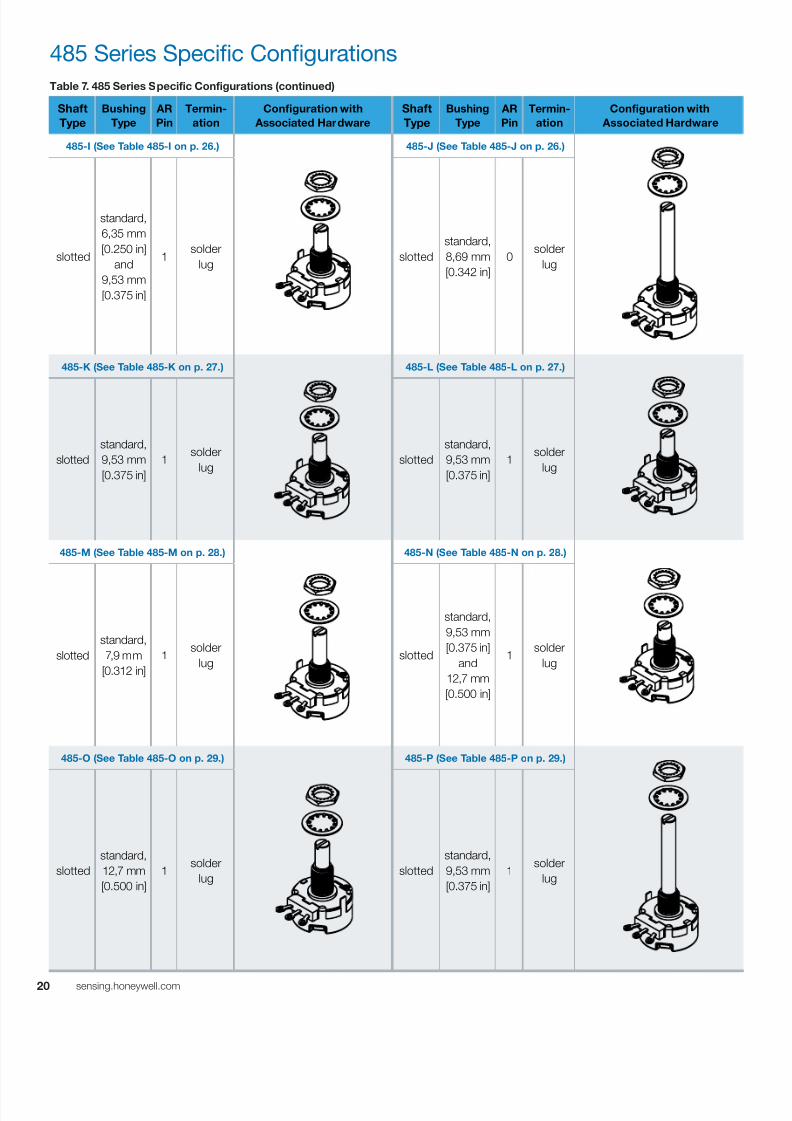
Table 7. 485 Series Specific Configurations (continued)
Shaft
Type
Bushing
Type
AR
Pin
Termin-
ation
Configuration with
Associated Hardware
Shaft
Type
Bushing
Type
AR
Pin
Termin-
ation
Configuration with
Associated Hardware
485-I (See Table 485-I on p. 26.) 485-J (See Table 485-J on p. 26.)
slotted
standard,
6,35 mm
[0.250 in]
and
9,53 mm
[0.375 in]
1 solder
lug slotted
standard,
8,69 mm
[0.342 in]
0 solder
lug
485-K (See Table 485-K on p. 27.) 485-L (See Table 485-L on p. 27.)
slotted
standard,
9,53 mm
[0.375 in]
1 solder
lug slotted
standard,
9,53 mm
[0.375 in]
1 solder
lug
485-M (See Table 485-M on p. 28.) 485-N (See Table 485-N on p. 28.)
slotted
standard,
7,9 mm
[0.312 in]
1 solder
lug slotted
standard,
9,53 mm
[0.375 in]
and
12,7 mm
[0.500 in]
1 solder
lug
485-O (See Table 485-O on p. 29.) 485-P (See Table 485-P on p. 29.)
slotted
standard,
12,7 mm
[0.500 in]
1 solder
lug slotted
standard,
9,53 mm
[0.375 in]
1 solder
lug

7/23/2019 Honeywell Sensing Potentiometers 380 Rv4 485 53c 385 Datasheet 32301266 a En
http://slidepdf.com/reader/full/honeywell-sensing-potentiometers-380-rv4-485-53c-385-datasheet-32301266-a-en 21/47
2sensing.honeywell.com
Table 7. 485 Series Specific Configurations (continued)
Shaft
Type
Bushing
Type
AR
Pin
Termin-
ation
Configuration with
Associated Hardware
Shaft
Type
Bushing
Type
AR
Pin
Termin-
ation
Configuration with
Associated Hardware
485-Q (See Table 485-Q on p. 30.) 485-R (See Table 485-R on p. 30.)
slotted
standard,
9,53 mm
[0.375 in]
1
solder
lug
with
center tap
round
standard,
9,53 mm
[0.375 in]
1 solder
lug
485-S (See Table 485-S on p. 31.) 485-T (See Table 485-T on p. 31)
slotted
standard,
12,7 mm
[0.500 in]
1solder
lug
straight
knurled
standard,
8,67 mm
[0.342 in]
1 solder
lug
485 Series Specific Configurations
7/23/2019 Honeywell Sensing Potentiometers 380 Rv4 485 53c 385 Datasheet 32301266 a En
http://slidepdf.com/reader/full/honeywell-sensing-potentiometers-380-rv4-485-53c-385-datasheet-32301266-a-en 22/47
22 sensing.honeywell.com
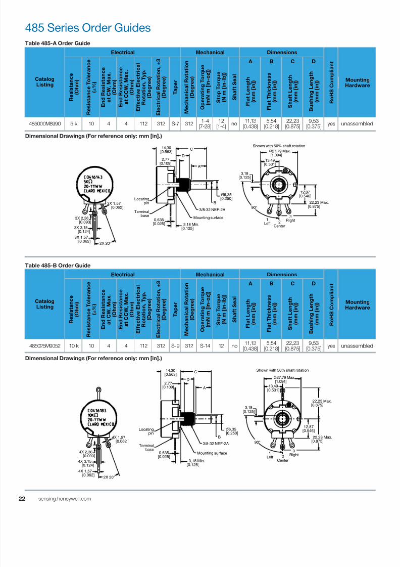
485 Series Order GuidesTable 485-A Order Guide
CatalogListing
Electrical Mechanical Dimensions
R o
H S C o m p
l i a n
t
MountingHardware
R
e s
i s t a n c e
( O h m
)
R e s
i s t a n c e
T o
l e r a n c e
( ± % )
E n d
R e s
i s t a n c e
a t
C W
, M a x .
( O h m
)
E n d
R e s
i s t a n c e
a t
C C W
, M a x .
( O h m
)
E f f e c
t i v e
E l e c
t r i c a
l
R o
t a t i o n ,
T y p .
( D e g r e e
)
E l e c
t r i c a
l R o
t a t i o n , ±
3
( D e g r e e
)
T a p e r
M e c h a
n i c a
l R o
t a t i o n
( D e g r e e
)
O p e r a
t i n g
T o r q u e
( m N m
[ i n - o z
] )
S t
o p
T o r q u e
( N
m
[ i n - l b
] )
S
h a
f t S e a
l
A B C D
F l a t L e n g
t h
( m
m
[ i n ] )
F l a t T h i c k n e s s
( m
m
[ i n ] )
S h a f t L e n g
t h
( m
m
[ i n ] )
B u s h
i n g
L e n g
t h
( m
m
[ i n ] )
485000M8990 5 k 10 4 4 112 312 S-7 312 1-4[7-28]
12[1-4]
no 11,13[0.438]
5,54[0.218]
22,23[0.875]
9,53[0.375]
yes unassembled
Dimensional Drawings (For reference only: mm [in].)
Table 485-B Order Guide
CatalogListing
Electrical Mechanical Dimensions
R o
H S C o m p
l i a n
t
MountingHardware
R e s
i s t a n c e
( O h m
)
R e s
i s t a n c e
T o l e
r a n c e
( ± % )
E n
d R e s
i s t a n
c e
a t C W
, M a x
.
( O h m
)
E n
d R e s
i s t a n
c e
a t C C W
, M a
x .
( O h m
)
E f f e c
t i v e
E l e c t
r i c a
l
R o
t a t i o n , T y
p .
( D e g r e e )
E l e c
t r i c a
l R o
t a t i o n , ±
3
( D e g r e e )
T a p e r
M e c
h a n
i c a
l R o t a t i o n
( D e g r e e )
O p e r a
t i n g
T o r
q u e
( m N m
[ i n - o z
] )
S t o p
T o r q u e
( N m
[ i n - l b
] )
S h a
f t S e a
l
A B C D
F l a t L e n g
t h
( m m
[ i n ] )
F l a t T h i c k n e s s
( m m
[ i n ] )
S h a
f t L e n g
t h
( m m
[ i n ] )
B u s
h i n g
L e n g t
h
( m m
[ i n ] )
485025M9052 10 k 10 4 4 112 312 S-9 312 S-14 12 no 11,13[0.438]
5,54[0.218]
22,23[0.875]
9,53[0.375]
yes unassembled
Dimensional Drawings (For reference only: mm [in].)
Mounting surface
A
B
2X 20°
3X 1,57 [0.062]
3X 2,36 [0.093]
3X 1,57 [0.062]
3X 3,15 [0.124]
90°
3,18[0.125]
C
1Left 2
Center
3Right
3/8-32 NEF-2A
3,18 Min.[0.125]
D
ø6,35
[0.250]Locating pin
Terminal base
0,635[0.025]
Shown with 50% shaft rotation
ø27,79 Max. [1.094]
13,49[0.531]
12,87[0.546]
22,23 Max.[0.875]
2,77[0.109]
14,30[0.563]
Locating pin
14,30[0.563]
90°
3,18[0.125]
Shown with 50% shaft rotation
1Left 2
Center
3RightMounting surface
3/8-32 NEF-2A
ø27,79 Max. [1.094]
13,49[0.531]
22,23 Max.[0.875]
Terminal base
2X 20°
4X 2,36 [0.093]
4X 1,57 [0.062]
4X 3,15 [0.124]
3,18 Min.[0.125]
0,635[0.025]
ø6,35 [0.250]
A
B
D
12,87[0.546]
22,23 Max.[0.875]
2,77[0.109]
C
4X 1,57 [0.062]

7/23/2019 Honeywell Sensing Potentiometers 380 Rv4 485 53c 385 Datasheet 32301266 a En
http://slidepdf.com/reader/full/honeywell-sensing-potentiometers-380-rv4-485-53c-385-datasheet-32301266-a-en 23/47
2sensing.honeywell.com
485 Series Order Guides
Table 485-C Order Guide
CatalogListing
Electrical Mechanical Dimensions
R o
H S C o m p
l i a n
t
MountingHardware
R
e s
i s t a n c e
( O h m
)
R e s
i s t a n c e
T o
l e r a n c e
( ± % )
E n d
R e s
i s t a n c e
a t
C W
, M a x .
( O h m
)
E n d
R e s
i s t a n c e
a t C C W
, M a x .
( O h m
)
E f f e c t i v e
E l e c
t r i c a
l
R o t a t i o n ,
T y p .
( D e g r e e
)
E l e c
t r i c
a l R o
t a t i o n , ±
3
( D e g r e e
)
T a p e r
M e c h a
n i c a
l R o
t a t i o n
( D e g r e e
)
O p e r
a t i n g
T o r q u e
( m N m
[ i n - o z
] )
S t
o p
T o r q u e
( N
m
[ i n - l b
] )
S
h a
f t S e a
l
A B
ShaftLength
(mm [in])
Bushing Length
(mm [in])
485025M8843 10 k 10 4 4 112 312 S-13 312 1-4[7-28]
12[1.4]
no 15,88
[0.625]6,35
[0.250] yes unassembled
485025M9267 5 k 10 4 4 112 312 S-13 312 1-4[7-28]
12[1.4]
no 15,88
[0.625]6,35
[0.250] yes unassembled
Dimensional Drawings (For reference only: mm [in].)
Table 485-D Order Guide
CatalogListing
Electrical Mechanical Dimensions
R o
H S C o m p
l i a n t
MountingHardware
R e s
i s t a n c e
( O h m
)
R e s
i s t a n c e
T o
l e r a n c e
( ± % )
E n
d R e s
i s t a n c e
a t C W
, M a x .
( O h m
)
E n
d R e s
i s t a n c e
a t C C W
, M a x .
( O h m
)
E f f e c
t i v e
E l e c
t r i c a l
R o
t a t i o n ,
T y p .
( D e g r e e
)
E l e c
t r i c a
l R o
t a t i o n , ±
3
( D e g r e e
)
T a p e r
M e c
h a n
i c a
l R o
t a t i o n
( D e g r e e
)
O p e r a
t i n g
T o r q u e
( m N m
[ i n - o z
] )
S t o p
T o r q u e
( N m
[ i n - l b
] )
S h a
f t S e a
l
A B
Shaft Length
(mm [in])
Bushing Length
(mm [in])
485008M7167 5 k 10 4 4 284 312 S-4 312 1-6[7-42]
12[1.4]
yes 22,23
[0.875]9,53
[0.375] yes unassembled
Dimensional Drawings (For reference only: mm [in].)
3,18[0.125]
Shown with 50% shaft rotation
1Left 2
Center
3RightMounting surface
3/8-32 NEF-2A
ø27,79 Max. [1.094]
13,49[0.531]
22,23 Max.[0.875]
Locating pin
Terminal base
2X 20°
4X 2,36 [0.093]
4X 1,57 [0.062]
4X 3,15 [0.124]
3,18 Min.[0.125]
0,635[0.025]
ø6,35[0.250]
14,30[0.563]
A
B
12,87[0.546]
22,23 Max.[0.875]
2,77[0.109]
4X 1,57 [0.062]
3,18[0.125]
1Left 2
Center
3Right
Mounting surface
3/8-32 NEF-2A
Locating pin
Terminal base
2X 20°
3X 2,36 [0.093]
3X 1,57 [0.062]
3X 3,15 [0.124]
3,18 Min.[0.125]
0,635[0.025]
ø6,32 [0.249]
14,30[0.563]
Shown with 50% shaft rotation
ø27,79 Max. [1.094]
13,49[0.531]
A
B
12,87[0.546]
22,23 Max.[0.875]
2,77
[0.109]
3X 1,57 [0.062]

7/23/2019 Honeywell Sensing Potentiometers 380 Rv4 485 53c 385 Datasheet 32301266 a En
http://slidepdf.com/reader/full/honeywell-sensing-potentiometers-380-rv4-485-53c-385-datasheet-32301266-a-en 24/47
24 sensing.honeywell.com
Table 485-E Order Guide
CatalogListing
Electrical Mechanical Dimensions
R o
H S C o m p
l i a n
t
MountingHardware
R
e s
i s t a n c e
( O h m
)
R e s
i s t a n c e
T o
l e r a n c e
( ± % )
E n d
R e s
i s t a n c e
a t
C W
, M a x .
( O h m
)
E n d
R e s
i s t a n c e
a t C C W
, M a x .
( O h m
)
E f f e c t i v e
E l e c
t r i c a
l
R o t a t i o n ,
T y p .
( D e g r e e
)
E l e c
t r i c
a l R o
t a t i o n , ±
3
( D e g r e e
)
T a p e r
M e c h a
n i c a
l R o
t a t i o n
( D e g r e e
)
O p e r
a t i n g
T o r q u e
( m N m
[ i n - o z
] )
S t
o p
T o r q u e
( N
m
[ i n - l b
] )
S
h a
f t S e a
l
A B
Shaft Length
(mm [in])
Bushing Length
(mm [in])
485000M8930 5 k 10 4 4 284 312 S-16 312 1-4[7-28]
12[1.4]
no 50,8
[2.000]9,53
[0.375] yes unassembled
Dimensional Drawings (For reference only: mm [in].)
485 Series Order Guides
Table 485-F Order Guide
CatalogListing
Electrical Mechanical Dimensions
R o
H S C o m p
l i a n
t
MountingHardware
R e s
i s t a n c e
( O h m
)
R e s
i s t a n c e
T o l e r a n c e
( ± % )
E n
d R e s
i s t a n
c e
a t C W
, M a x
.
( O h m
)
E n
d R e s
i s t a n
c e
a t C C W
, M a x .
( O h m
)
E f f e c
t i v e
E l e c t r i c a
l
R o
t a t i o n ,
T y p .
( D e g r e e )
E l e c
t r i c a
l R o
t a t i o n , ±
3
( D e g r e e )
T a p e r
M e c
h a n
i c a
l R o t a
t i o n
( D e g r e e )
O p e r a
t i n g
T o r q u e
( m N m
[ i n - o z
] )
S t o p
T o r q u e
( N m
[ i n - l b ]
)
S h a
f t S e a l
A B
Shaft Length
(mm [in])
BushingLength
(mm [in])
485000M9156 10 k 10 4 100 284 312 S-11 312 1-4[7-28]
12[1.4]
no 31,75
[1.250]9,53
[0.375] yes unassembled
Dimensional Drawings (For reference only: mm [in].)
3,18[0.125]
1Left 2
Center
3Right
Mounting surface
3/8-32 NEF-2A
Locating pin
Terminal base
2X 20°
3X 2,36 [0.093]
3X 1,57 [0.062]
3X 3,15 [0.124]
3,18 Min.[0.125]
0,635[0.025]
ø6,35[0.25]
14,30[0.563]
Shown with 50% shaft rotation
ø27,79 Max. [1.094]
13,49[0.531]
A
B
12,87[0.546]
22,23 Max.[0.875]
2,77[0.109]
3X 1,57
[0.062]
3,18[0.125]
1Left 2
Center
3Right
Mounting surface
3/8-32 NEF-2A
2X 20°
3X 1,57 [0.062]
3X 2,36 [0.093]
3X 1,57 [0.062]
3X 3,15 [0.124]
Locating pin
Terminal base
3,18 Min.[0.125]
0,635[0.025]
14,30[0.563]
Shown with 50% shaft rotation
ø27,79 Max. [1.094]
13,49[0.531]
A
B
12,87[0.546]
22,23 Max.[0.875]
ø6,35 [0.250]
2,77[0.109]

7/23/2019 Honeywell Sensing Potentiometers 380 Rv4 485 53c 385 Datasheet 32301266 a En
http://slidepdf.com/reader/full/honeywell-sensing-potentiometers-380-rv4-485-53c-385-datasheet-32301266-a-en 25/47
2sensing.honeywell.com
485 Series Order Guides
Table 485-H Order Guide
CatalogListing
Electrical Mechanical Dimensions
R o
H S C o m p
l i a n
t
MountingHardware
R e s
i s t a n c e
( O h m
)
R e s
i s t a n c e
T o
l e r a n c e
( ± % )
E n
d R e s
i s t a n c e
a t C W
, M a x .
( O h m
)
E n
d R e s
i s t a n c e
a t C C W
, M a x
.
( O h m
)
E f f e c
t i v e
E l e c t r i c a
l
R o
t a t i o n ,
T y p .
( D e g r e e )
E l e c
t r i c a
l R o
t a t i o n , ±
3
( D e g r e e )
T a p e r
M e c
h a n
i c a
l R o t a
t i o n
( D e g r e e )
O p e r a
t i n g
T o r q u e
( m N m
[ i n - o z
] )
S t o p
T o r q u e
( N m
[ i n - l b ]
)
S h a
f t S e a l
A B C D
S l o t L e n g
t h
( m m
[ i n ] )
S l o t W i d t h
( m m
[ i n ] )
S h a
f t L e n g
t h
( m m
[ i n ] )
B u s
h i n g
L e n g t
h
( m m
[ i n ] )
485025M9428 10 k 10 4 4 263 312 S-8 312 1-6[7-42]
12[1.4]
no 1,60[0.063]
1,19[0.047]
22,23[0.875]
9,53[0.375]
yes unassembled
485042M9576 1 k 10 4 4 263 312 S-8 312 1-6[7-42]
12[1.4]
no 1,60[0.063]
1,19[0.047]
22,23[0.875]
9,53[0.375]
yes unassembled
Dimensional Drawings (For reference only: mm [in].)
Table 485-G Order Guide
8.5
Electrical Mechanical Dimensions
R o
H S C o m p
l i a n
t
MountingHardware
R
e s
i s t a n c e
( O h m
)
R e s
i s t a n c e
T o
l e r a n c e
( ± % )
E n d
R e s
i s t a n c e
a t
C W
, M a x .
( O h m
)
E n d
R e s
i s t a n c e
a t C C W
, M a x .
( O h m
)
E f f e c t i v e
E l e c
t r i c a
l
R o t a t i o n ,
T y p .
( D e g r e e
)
E l e c
t r i c
a l R o
t a t i o n , ±
3
( D e g r e e
)
T a p e r
M e c h a
n i c a
l R o
t a t i o n
( D e g r e e
)
O p e r
a t i n g
T o r q u e
( m N m
[ i n - o z
] )
S t
o p
T o r q u e
( N
m
[ i n - l b
] )
S
h a
f t S e a
l
A B
ShaftLength
(mm [in])
BushingLength
(mm [in])
485004M8986 25 k 10 4 4 180 348 S-6 360 1-4[7-28]
- no 76,2
[3.000]9,53
[0.375] yes unassembled
Dimensional Drawings (For reference only: mm [in].)
3,18[0.125]
1Left 2
Center
3Right
Mounting surface
3/8-32 NEF-2A
2X 20°
3X 1,57 [0.062]
3X 2,36 [0.093]
3X 1,57 [0.062]
3X 3,15 [0.124]
Terminal base
3,18 Min.[0.125]
0,635[0.025]
14,30[0.563]
Shown with 50% shaft rotation ø27,79 Max.
[1.094]
13,49[0.531]
A
B
12,87
[0.546] 22,23 Max.
[0.875]
2,77[0.109]
Locatingpin
ø6,32 [0.249]
2,39
[0.094]
ø1,58 [0.062]
3,18[0.125]
1Left 2
Center
3RightMounting surface
3/8-32 NEF-2A 90°
3X 1,57 [0.062]
4X 2,36 [0.093]
4X 1,57 [0.062]
4X 3,15 [0.124]
Locating pin
Terminal base
3,18 Min.[0.125]
0,635[0.025]
14,30[0.563]
A
B
D
C
12,87[0.546]
22,23 Max.[0.875]
ø6,35 [0.250]
2,77[0.109]
Shown with 50% shaft rotation
ø27,79 Max. [1.094]
13,49[0.531]
22,23 Max.[0.875]
2X 20°

7/23/2019 Honeywell Sensing Potentiometers 380 Rv4 485 53c 385 Datasheet 32301266 a En
http://slidepdf.com/reader/full/honeywell-sensing-potentiometers-380-rv4-485-53c-385-datasheet-32301266-a-en 26/47
26 sensing.honeywell.com
Table 485-I Order Guide
CatalogListing
Electrical Mechanical Dimensions
R o
H S C o m p
l i a n
t
MountingHardware
R
e s
i s t a n c e
( O h m
)
R e s
i s t a n c e
T o
l e r a n c e
( ± % )
E n d
R e s
i s t a n c e
a t
C W
, M a x .
( O h m
)
E n d
R e s
i s t a n c e
a t C C W
, M a x .
( O h m
)
E f f e c t i v e
E l e c
t r i c a
l
R o t a t i o n ,
T y p .
( D e g r e e
)
E l e c
t r i c
a l R o
t a t i o n , ±
3
( D e g r e e
)
T a p e r
M e c h a
n i c a
l R o
t a t i o n
( D e g r e e
)
O p e r
a t i n g
T o r q u e
( m N m
[ i n - o z
] )
S t
o p
T o r q u e
( N
m
[ i n - l b
] )
S
h a
f t S e a
l
A B C D
S l o t L e n g
t h
( m
m
[ i n ] )
D e p
t h W i d t h
( m
m
[ i n ] )
S h a f t L e n g
t h
( m
m
[ i n ] )
B u s h
i n g
L e n g
t h
( m
m
[ i n ] )
485000M8723 5 k 10 4 4 284 312 S-9 312 1-4[1-28]
12[1.4] no 1,60
[0.063]1,19
[0.047]22,23[0.875]
9,53[0.375]
yes unassembled
485000M9564 50 k 10 4 4 284 312 S-9 312 1-4[1-28]
12[1.4] no 1,60
[0.063]1,19
[0.047]22,23[0.875]
9,53[0.75]
yes unassembled
485000M9641 10 k 10 4 4 284 312 S-9 312 1-4[1-28]
12[1.4] no 1,60
[0.063]1,19
[0.047]22,23[0.875]
9,53[0.375] yes unassembled
485000M9708 1 k 10 4 4 284 312 S-9 312 1-4[1-28]
12[1.4] no 1,60
[0.063]1,19
[0.047]15,88[0.625]
6,35[0.250]
yes unassembled
Dimensional Drawings (For reference only: mm [in].)
485 Series Order Guides
Table 485-J Order Guide
CatalogListing
Electrical Mechanical Dimensions
R o
H S C o m p
l i a n
t
MountingHardware
R e s
i s t a n c e
( O h m
)
R e s
i s t a n c e
T o
l e r a n c e
( ± % )
E n
d R e s
i s t a n c e
a t C W
, M a x .
( O h m
)
E n
d R e s
i s t a n c e
a t C C W
, M a x .
( O h m
)
E f f e c
t i v e
E l e c
t r i c a
l
R o
t a t i o n ,
T y p .
( D e g r e e
)
E l e c
t r i c a
l R o
t a t i o n , ±
3
( D e g r e e
)
T a p e r
M e c
h a n
i c a
l R o
t a t i o n
( D e g r e e
)
O p e r a
t i n g
T o r q u e
( m N m
[ i n - o z
] )
S t o p
T o r q u e
( N m
[ i n - l b
] )
S h a
f t S e a
l
A B C D
S l o t D e p
t h
( m m
[ i n ] )
S l o t W i d t h
( m m
[ i n ] )
S h a
f t L e n g
t h
( m m
[ i n ] )
B u s
h i n g
L e n g
t h
( m m
[ i n ] )
485000M9017 1 M 10 10 10 284 312 S-4 312 1-4[1-28]
12[1.4]
no 1,60[0.063]
1,19[0.047]
50,8[2.000]
9,53[0.375]
yes unassembled
Dimensional Drawings (For reference only: mm [in].)
3,18[0.125]
1Left 2
Center
3Right
Mounting surface
3/8-32 NEF-2A 90°
2X 20°
3X 1,57 [0.062]
3X 2,36 [0.093]
3X 1,57 [0.062]
3X 3,15 [0.124]
Locating pin
Terminal base
3,18 Min.[0.125]
0,635[0.025]
14,30[0.563]
Shown with 50% shaft rotation
ø27,79 Max. [1.094]
13,49[0.531]
BA
D
C
12,87[0.546]
22,23 Max.[0.875]
ø6,35 [0.250]
2,77[0.109]
3,18[0.125]
Shown with 50% shaft rotation
1Left 2
Center
3Right
Mounting surface
3/8-32 NEF-2A90°
ø27,79 Max. [1.094]
13,49[0.531]
2X 20°
3X 1,57 [0.062]
3X 2,36 [0.093]
3X 1,57 [0.062]
3X 3,15 [0.124]
Terminal base
3,18 Min.[0.125]
0,635[0.025]
14,30[0.563]
BA
D
C
12,87[0.546]
22,23 Max.[0.875]
ø6,35 [0.250]
2,77[0.109]

7/23/2019 Honeywell Sensing Potentiometers 380 Rv4 485 53c 385 Datasheet 32301266 a En
http://slidepdf.com/reader/full/honeywell-sensing-potentiometers-380-rv4-485-53c-385-datasheet-32301266-a-en 27/47
2sensing.honeywell.com
485 Series Order Guides
Table 485-K Order Guide
CatalogListing
Electrical Mechanical Dimensions
R o H
S C o m p
l i a n
t
MountingHardware
R e s
i s t a n c e
( O
h m
)
R e s
i s t a n c e
T o
l e r a n c e
( ± % )
E n
d R e s
i s t a n c e
a t C W
, M a x .
( O
h m
)
E n
d R e s
i s t a n c e
a t C C
W ,
M a x .
( O
h m
)
E f f e c
t i v
e E l e c
t r i c a
l
R o
t a t i o n ,
T y p .
( D e g r e e
)
E l e c
t r i c a l R o
t a t i o n , ±
3
( D e g r e e
)
T
a p e r
M e c
h a n
i c a
l R o
t a t i o n
( D e g r e e
)
O p e r a t
i n g
T o r q u e
( m N m
[ i n - o z
] )
S t o p
T o r q u e
( N m
[ i n - l b
] )
S h a
f t S e a
l
A B C D
S l o t D
e p
t h
( m m
[ i n ] )
S l o t W
i d t h
( m m
[ i n ] )
S h a
f t L
e n g
t h
( m m
[ i n ] )
B u s
h i n g
L e n g
t h
( m m
[ i n ] )
485042M9668 10 k 10 4 100 284 311 S-7 312 1-6[7-42]
12[1.4]
yes 1,60[0.063]
1,19[0.047]
22,23[0.875]
9,53[0.375]
yes unassembled
Dimensional Drawings (For reference only: mm [in].)
Table 485-L Order Guide
CatalogListing
Electrical Mechanical Dimensions
R o
H S C o m p
l i a n t
MountingHardware
R e s
i s t a n c e
( O h m
)
R e s
i s t a n c e
T o
l e r a n c e
( ± % )
E n
d R e s
i s t a n c e
a t C W
, M a x .
( O h m
)
E n
d R e s
i s t a n c e
a t C C W
, M a x .
( O h m
)
E f f e c
t i v e
E l e c
t r i c a l
R o
t a t i o n ,
T y p .
( D e g r e e
)
E l e c
t r i c a
l R o
t a t i o n , ±
3
( D e g r e e
)
T a p e r
M e c
h a n
i c a
l R o
t a t i o n
( D e g r e e
)
O p e r a
t i n g
T o r q u e
( m N m
[ i n - o z
] )
S t o p
T o r q u e
( N m
[ i n - l b
] )
S h a
f t S e a
l
A B C D
S l o t D e p
t h
( m m
[ i n ] )
S l o t W i d t h
( m m
[ i n ] )
S h a
f t L e n g
t h
( m m
[ i n ] )
B u s
h i n g
L e n g
t h
( m m
[ i n ] )
485000M8911 1 M 10 10 10 304 312 S -2 312 1-4[7-28]
12[1.4]
no 1,60[0.063]
1,19[0.047]
22,23[0.875]
9,53[0.375]
yes unassembled
Dimensional Drawings (For reference only: mm [in].)
1Left 2
Center
3Right
Mounting surface
3/8-32 NEF-2A90°
12,87[0.546]
22,23 Max.[0.875]
3,18 Min.[0.125]
3,18[0.125]
Shown with 50% shaft rotation
ø27,79 Max. [1.094]
13,49[0.531]
B
2X 20°
3X 1,57 [0.062]
3X 2,36 [0.093]
3X 1,57 [0.062]
3X 3,15 [0.124]
Locating pin
Terminal base
0,635[0.025]
ø6,35 [0.250]
A
D
C
2,77[0.109]
14,30[0.563]
1Left 2
Center
3Right
90°
Shown with 50% shaft rotation
ø27,79 Max. [1.094]
13,49
[0.531]B
2X 20°
3X 2,36 [0.093]
3X 1,57 [0.062]
3X 3,15 [0.124]
Locating pin
Terminal base
3,18 Min.[0.125]
0,635[0.025]
ø6,35 [0.250]
Mounting surface
3/8-32 NEF-2A
C
A
D
12,87[0.546]
22,23 Max.[0.875]
2,77[0.109]
14,30[0.563]
3,18[0.125]
3X 1,57 [0.062]

7/23/2019 Honeywell Sensing Potentiometers 380 Rv4 485 53c 385 Datasheet 32301266 a En
http://slidepdf.com/reader/full/honeywell-sensing-potentiometers-380-rv4-485-53c-385-datasheet-32301266-a-en 28/47
28 sensing.honeywell.com
485 Series Order Guides
Table 485-M Order Guide
CatalogListing
Electrical Mechanical Dimensions
R o
H S C o m p
l i a n
t
MountingHardware
R
e s
i s t a n c e
( O h m
)
R e s
i s t a n c e
T o
l e r a n c e
( ± % )
E n d
R e s
i s t a n c e
a t
C W
, M a x .
( O h m
)
E n d
R e s
i s t a n c e
a t C C W
, M a x .
( O h m
)
E f f e c t i v e
E l e c
t r i c a
l
R o t a t i o n ,
T y p .
( D e g r e e
)
E l e c
t r i c
a l R o
t a t i o n , ±
3
( D e g r e e
)
T a p e r
M e c h a
n i c a
l R o
t a t i o n
( D e g r e e
)
O p e r
a t i n g
T o r q u e
( m N m
[ i n - o z
] )
S t
o p
T o r q u e
( N
m
[ i n - l b
] )
S
h a
f t S e a
l
A B C D
S l o
t D e p
t h
( m
m
[ i n ] )
S l o
t W i d t h
( m
m
[ i n ] )
S h a f t L e n g
t h
( m
m
[ i n ] )
B u s h
i n g
L e n g
t h
( m
m
[ i n ] )
485010M6860 5 k 10 4 4 33 312 S-9 312 1-4[7-28]
12[1.4] no 1,60
[0.063]1,19
[0.047]27,19[1.031]
7,92[0.312] yes unassembled
Dimensional Drawings (For reference only: mm [in].)
Table 485-N Order Guide
CatalogListing
Electrical Mechanical Dimensions
R o H
S C o m p
l i a n
t
MountingHardware
R e s
i s t a n c e
( O h m
)
R e s
i s t a n c e
T o
l e r a n c e
( ± % )
E n
d R
e s
i s t a n c e
a t C
W ,
M a x .
( O h m
)
E n
d R
e s
i s t a n c e
a t C
C W
, M a x .
( O h m
)
E f f e c t i v e
E l e c
t r i c a
l
R o t a
t i o n ,
T y p .
( D
e g r e e
)
E l e c
t r i c a
l R o
t a t i o n , ±
3
( D
e g r e e
)
T a p e r
M e c
h a n
i c a
l R o
t a t i o n
( D
e g r e e
)
O p e r a
t i n g
T o r q u e
( m N
m [ i n - o z
] )
S t o
p T o r q u e
( N m
[ i n - l b
] )
S h
a f t S e a
l
A B C D
S l o t
D e p
t h
( m m
[ i n ] )
S l o t
W i d t h
( m m
[ i n ] )
S h a f t
L e n g
t h
( m m
[ i n ] )
B u s
h i n
g L e n g
t h
( m m
[ i n ] )
485000M8990 5 k 10 4 4 45 312 S-10 312 1-6[7-42]
12[1.4] yes 1,60
[0.063]1,19
[0.047]20,62[0.182]
12,7[0.500] yes unassembled
485008M0002 5 k 10 4 4 45 312 S-10 312 1-6[7-42]
12[1.4] yes 1,60
[0.063]1,19
[0.047]50,8
[2.000]12,7
[0.500] no unassembled
485008M8967 5 k 10 4 4 45 312 S-10 312 1-6[7-42]
12[1.4] yes 1,60
[0.063]1,19
[0.047]50,8
[2.000]12,7
[0.500] yes unassembled
485008M9458 5 k 10 4 4 45 312 S-10 312 1-6[7-42]
12[1.4] yes 1,60
[0.063]1,19
[0.047]50,8
[2.000]9,53
[0.375] yes unassembled
485008M9687 5 k 10 4 4 45 312 S-10 312 1-6[7-42]
12[1.4] yes 1,60
[0.063]1,19
[0.047]47,63[1.875]
9,53[0.375] yes unassembled
485008M9688 5 k 10 4 4 45 312 S-A 312 1-6[7-42]
12[1.4] yes 1,60
[0.063]1,19
[0.047]39,88[1.570]
12,7[0.500] yes unassembled
Dimensional Drawings (For reference only: mm [in].)
1Left 2
Center
3Right
90°
Shown with 50% shaft rotation
ø27,79 Max. [1.094]
13,49[0.531]
B
2X 20°
3X 2,36 [0.093]
3X 1,57 [0.062]
3X 3,15 [0.124]
Locating pin
Terminal base
3,18 Min.[0.125]
0,635[0.025]
Mounting surface
3/8-32 NEF-2A
ø6,35 [0.250]
C
A
D
12,87[0.546]
22,23 Max.
[0.875]
14,30[0.563]
3,18[0.125]
2,77[0.109]
3X 1,57
[0.062]
90°
Shown with 50% shaft rotation
ø27,79 Max. [1.094]13,49
[0.531]B
2X 20°
3X 2,36 [0.093]
3X 1,57 [0.062]
3X 3,15 [0.124]
Locating pin
Terminal base
3,18 Min.[0.125]
0,635[0.025]
ø6,35 [0.250]
Mounting surface
3/8-32 NEF-2A
C
A
D
12,87[0.546]
22,23 Max.[0.875]
2,77[0.109]
14,30
[0.563]
3,18[0.125]
3X 1,57 [0.062]
1Left 2
Center
3Right
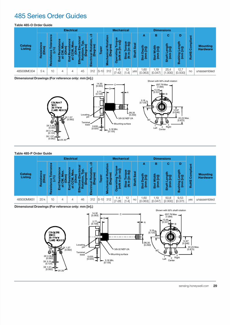
7/23/2019 Honeywell Sensing Potentiometers 380 Rv4 485 53c 385 Datasheet 32301266 a En
http://slidepdf.com/reader/full/honeywell-sensing-potentiometers-380-rv4-485-53c-385-datasheet-32301266-a-en 29/47
2sensing.honeywell.com
485 Series Order Guides
Table 485-O Order Guide
CatalogListing
Electrical Mechanical Dimensions
R o
H S C o m p
l i a n
t
MountingHardware
R
e s
i s t a n c e
( O h m
)
R e s
i s t a n c e
T o
l e r a n c e
( ± % )
E n d
R e s
i s t a n c e
a t
C W
, M a x .
( O h m
)
E n d
R e s
i s t a n c e
a t C C W
, M a x .
( O h m
)
E f f e c t i v e
E l e c
t r i c a
l
R o t a t i o n ,
T y p .
( D e g r e e
)
E l e c
t r i c
a l R o
t a t i o n , ±
3
( D e g r e e
)
T a p e r
M e c h a
n i c a
l R o
t a t i o n
( D e g r e e
)
O p e r
a t i n g
T o r q u e
( m N m
[ i n - o z
] )
S t
o p
T o r q u e
( N
m
[ i n - l b
] )
S
h a
f t S e a
l
A B C D
S l o
t D e p
t h
( m
m
[ i n ] )
S l o
t W i d t h
( m
m
[ i n ] )
S h a f t L e n g
t h
( m
m
[ i n ] )
B u s h
i n g
L e n g
t h
( m
m
[ i n ] )
485008M0004 5 k 10 4 4 45 312 S-10 312 1-6[7-42]
12[1.4]
yes 1,60[0.063]
1,19[0.047]
25,4[1.000]
12,7[0.500]
no unassembled
Dimensional Drawings (For reference only: mm [in].)
Table 485-P Order Guide
CatalogListing
Electrical Mechanical Dimensions
R o
H S C o m p
l i a n
t
MountingHardware
R e s
i s t a n c e
( O h m
)
R e s
i s t a n c e
T o
l e r
a n c e
( ± % )
E n
d R e s
i s t a n c e
a t C W
, M a x .
( O h m
)
E n
d R e s
i s t a n c e
a t C C W
, M a x
.
( O h m
)
E f f e c
t i v e
E l e c t r
i c a
l
R o
t a t i o n ,
T y p
.
( D e g r e e )
E l e c
t r i c a
l R o
t a t i o
n , ±
3
( D e g r e e )
T a p e r
M e c
h a n
i c a
l R o t a
t i o n
( D e g r e e )
O p e r a
t i n g
T o r q
u e
( m N m
[ i n - o z
] )
S t o p
T o r q u e
( N m
[ i n - l b ] )
S h a
f t S e a l
A B C D
S l o t D e p
t h
( m m
[ i n ] )
S l o t W i d t h
( m m
[ i n ] )
S h a
f t L e n g
t h
( m m
[ i n ] )
B u s
h i n g
L e n g t h
( m m
[ i n ] )
485000M9651 20 k 10 4 4 46 312 S-10 312 1-4[7-28]
12[1.4]
no 1,60[0.063]
1,19[0.047]
50,8[2.000]
9,53[0.375]
yes unassembled
Dimensional Drawings (For reference only: mm [in].)
1Left 2
Center
3Right
90°
Shown with 50% shaft rotation
ø27,79 Max. [1.094]
13,49[0.531]
B
2X 20°
3X 2,36 [0.093]
3X 1,57 [0.062]
3X 3,15 [0.124]
Locating pin
Terminal base
3,18 Min.[0.125]
0,635[0.025]
ø6,35 [0.250]
Mounting surface
3/8-32 NEF-2A
C
A
D
2,77[0.109]
14,30[0.563]
3,18[0.125]
3X 1,57 [0.062]
22,23 Max.[0.875]
12,87[0.546]
1Left 2
Center
3Right
90°
Shown with 50% shaft rotation
ø27,79 Max. [1.094]
13,49[0.531]
B
2X 20°
3X 2,36 [0.093]
3X 1,57 [0.062]
3X 3,15 [0.124]
ø6,35 [0.250]
Mounting surface
3/8-32 NEF-2A
Locating pin
Terminal base
3,18 Min.[0.125]
0,635[0.025]
C
A
D
12,87[0.546]
22,23 Max.[0.875]
2,77[0.109]
14,30[0.563]
3,18[0.125]
3X 1,57 [0.062]
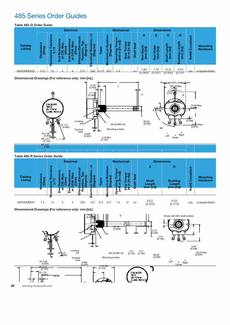
7/23/2019 Honeywell Sensing Potentiometers 380 Rv4 485 53c 385 Datasheet 32301266 a En
http://slidepdf.com/reader/full/honeywell-sensing-potentiometers-380-rv4-485-53c-385-datasheet-32301266-a-en 30/47
30 sensing.honeywell.com
Table 485-Q Order Guide
CatalogListing
Electrical Mechanical Dimensions
R o
H S C o m p
l i a n
t
MountingHardware
R
e s
i s t a n c e
( O h m
)
R e s
i s t a n c e
T o
l e r a n c e
( ± % )
E n d
R e s
i s t a n c e
a t
C W
, M a x .
( O h m
)
E n d
R e s
i s t a n c e
a t C C W
, M a x .
( O h m
)
E f f e c t i v e
E l e c
t r i c a
l
R o t a t i o n ,
T y p .
( D e g r e e
)
E l e c
t r i c
a l R o
t a t i o n , ±
3
( D e g r e e
)
T a p e r
M e c h a
n i c a
l R o
t a t i o n
( D e g r e e
)
O p e r
a t i n g
T o r q u e
( m N m
[ i n - o z
] )
S t
o p
T o r q u e
( N
m
[ i n - l b
] )
S
h a
f t S e a
l
A B C D
S l o
t D e p
t h
( m
m
[ i n ] )
S l o
t W i d t h
( m
m
[ i n ] )
S h a f t L e n g
t h
( m
m
[ i n ] )
B u s h
i n g
L e n g
t h
( m
m
[ i n ] )
485030M9652 10 k 10 4 4 270 348 S-12 360 1-4 - no 1,60[0.063]
1,19[0.047]
50,8[2.000]
9,53[0.375]
yes unassembled
Dimensional Drawings (For reference only: mm [in].)
Table 485-R Series Order Guide
CatalogListing
Electrical Mechanical Dimensions
R o
H S C o m p l i a
n t
MountingHardware
R e s
i s t a n c e
( O h m
)
R e s
i s t a n c e
T o
l e r a n
c e
( ± % )
E n
d R e s
i s t a n c e
a t C W
, M a x .
( O h m
)
E n
d R e s
i s t a n c e
a t C C W
, M a x .
( O h m
)
E f f e c
t i v e
E l e c
t r i c
a l
R o
t a t i o n ,
T y p .
( D e g r e e
)
E l e c
t r i c a
l R o
t a t i o n
, ±
3
( D e g r e e
)
T a p e r
M e c
h a n
i c a
l R o
t a t i o n
( D e g r e e
)
O p e r a
t i n g
T o r q u e
( m N m
[ i n - o z ] )
S t o p
T o r q u e
( N m
[ i n - l b
] )
S h a
f t S e a
l
A B
ShaftLength
(mm [in])
Bushing Length
(mm [in])
485040M9512 1 k 10 4 4 250 312 S-5 312 1-4 12 no 63,5
[2.500]9,53
[0.375] yes unassembled
Dimensional Drawings (For reference only: mm [in].)
485 Series Order Guides
1Left 2
Center
3Right
90°
°
4X 2,36 [0.093]
4X 1,57 0.062
4X 3,15 [0.124]
Locating pin
Terminal base
3,18 Min.[0.125]
0,635[0.025]
ø6,35 [0.250]
Mounting surface
3/8-32 NEF-2A
C
A B
D
12,87[0.546]
22,23 Max.[0.875]
14,30[0.563]
3,18[0.125]
2,77[0.109]
4X 1,57 [0.062]
ø27,79 Max. [1.094]
13,49[0.531]
22,56 Max.[0.888]
Shown with 50% shaft rotation
1Left 2
Center
3Right
Shown with 50% shaft rotation
ø27,79 Max. [1.094]
13,49
[0.531]
2X 20°
3X 2,36 [0.093]
3X 1,57 [0.062]
3X 3,15 [0.124]
ø6,35 [0.250]
Locating pin
Terminal base
3,18 Min.[0.125]
0,635[0.025]
Mounting surface
3/8-32 NEF-2A
D
C
12,87[0.546]
22,23 Max.[0.875]
2,77[0.109]
14,30[0.563]
3,18[0.125]
12,7[0.125]
12,7[0.125]
ø2,36 [0.093]
49,40[1.945]
5,70[0.226]
3X 1,57 [0.062]
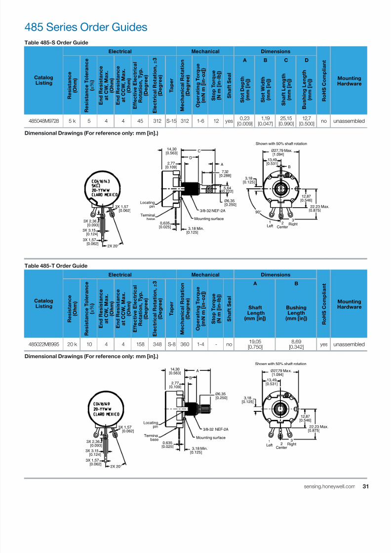
7/23/2019 Honeywell Sensing Potentiometers 380 Rv4 485 53c 385 Datasheet 32301266 a En
http://slidepdf.com/reader/full/honeywell-sensing-potentiometers-380-rv4-485-53c-385-datasheet-32301266-a-en 31/47
3sensing.honeywell.com
Table 485-S Order Guide
CatalogListing
Electrical Mechanical Dimensions
R o
H S C o m p
l i a n
t
MountingHardware
R
e s
i s t a n c e
( O h m
)
R e s
i s t a n c e
T o
l e r a n c e
( ± % )
E n d
R e s
i s t a n c e
a t
C W
, M a x .
( O h m
)
E n d
R e s
i s t a n c e
a t C C W
, M a x .
( O h m
)
E f f e c t i v e
E l e c
t r i c a
l
R o t a t i o n ,
T y p .
( D e g r e e
)
E l e c
t r i c
a l R o
t a t i o n , ±
3
( D e g r e e
)
T a p e r
M e c h a
n i c a
l R o
t a t i o n
( D e g r e e
)
O p e r
a t i n g
T o r q u e
( m N m
[ i n - o z
] )
S t
o p
T o r q u e
( N
m
[ i n - l b
] )
S
h a
f t S e a
l
A B C D
S l o
t D e p
t h
( m
m
[ i n ] )
S l o
t W i d t h
( m
m
[ i n ] )
S h a f t L e n g
t h
( m
m
[ i n ] )
B u s h
i n g
L e n g
t h
( m
m
[ i n ] )
485048M9728 5 k 5 4 4 45 312 S-15 312 1-6 12 yes 0,23[0.009]
1,19[0.047]
25,15[0.990]
12,7[0.500]
no unassembled
Dimensional Drawings (For reference only: mm [in].)
Table 485-T Order Guide
CatalogListing
Electrical Mechanical Dimensions
R o
H S C o m p l i a
n t
MountingHardware
R e s
i s t a n c e
( O h m
)
R e s
i s t a n c e
T o
l e r a n
c e
( ± % )
E n
d R e s
i s t a n c e
a t C W
, M a x .
( O h m
)
E n
d R e s
i s t a n c e
a t C C W
, M a x .
( O h m
)
E f f e c
t i v e
E l e c
t r i c
a l
R o
t a t i o n ,
T y p .
( D e g r e e
)
E l e c
t r i c a
l R o
t a t i o n
, ±
3
( D e g r e e
)
T a p e r
M e c
h a n
i c a
l R o
t a t i o n
( D e g r e e
)
O p e r a
t i n g
T o r q u e
( m N m
[ i n - o z ] )
S t o p
T o r q u e
( N m
[ i n - l b
] )
S h a
f t S e a
l
A B
Shaft Length
(mm [in])
BushingLength
(mm [in])
485022M8995 20 k 10 4 4 158 348 S-8 360 1-4 - no 19,05
[0.750]8,69
[0.342] yes unassembled
Dimensional Drawings (For reference only: mm [in].)
485 Series Order Guides
1Left
2Center
3Right
90°
Shown with 50% shaft rotation
ø27,79 Max. [1.094]
13,49[0.531]
B
2X 20°
3X 2,36 [0.093]
3X 1,57 [0.062]
3X 3,15 [0.124]
Locating pin
Terminal base
3,18 Min.[0.125]
0,635[0.025]
Mounting surface
3/8-32 NEF-2A
ø6,35 [0.250]
C
A
D
12,87[0.546]
22,23 Max.[0.875]
2,77[0.109]
14,30[0.563]
3,18[0.125]
7,32[0.288]
5,64[0.222]
3X 1,57 [0.062]
1Left 2
Center
3Right
Shown with 50% shaft rotation
ø27,79 Max. [1.094]
13,49[0.531]
2X 20°
3X 2,36 [0.093]
3X 1,57 [0.062]
3X 3,15 [0.124]
Locating pin
Terminal base
3,18 Min.[0.125]
0,635[0.025]
Mounting surface
3/8-32 NEF-2A
ø6,35 [0.250]
A
B
12,87[0.546]
22,23 Max.[0.875]
14,30[0.563]
3,18[0.125]
2,77
[0.109]
3X 1,57 [0.062]
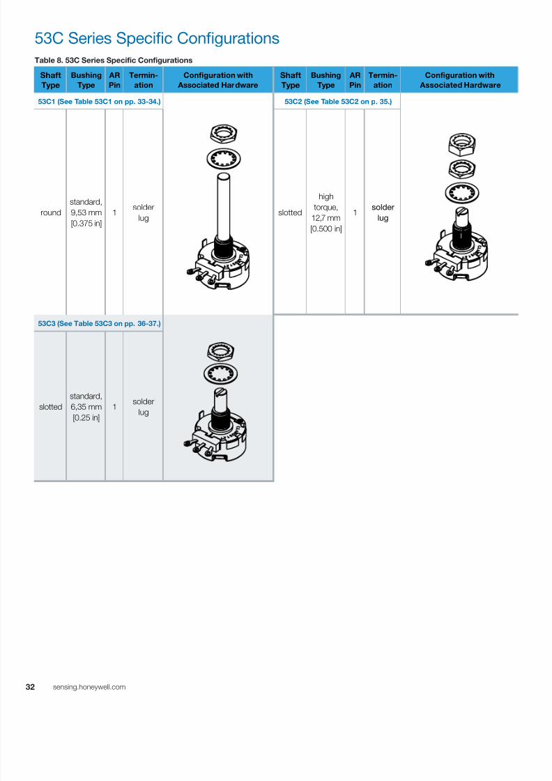
7/23/2019 Honeywell Sensing Potentiometers 380 Rv4 485 53c 385 Datasheet 32301266 a En
http://slidepdf.com/reader/full/honeywell-sensing-potentiometers-380-rv4-485-53c-385-datasheet-32301266-a-en 32/47
32 sensing.honeywell.com
53C Series Specific Configurations
Table 8. 53C Series Specific Configurations
Shaft
Type
Bushing
Type
AR
Pin
Termin-
ation
Configuration with
Associated Hardware
Shaft
Type
Bushing
Type
AR
Pin
Termin-
ation
Configuration with
Associated Hardware
53C1 (See Table 53C1 on pp. 33-34.) 53C2 (See Table 53C2 on p. 35.)
round
standard,
9,53 mm
[0.375 in]
1 solder
lug slotted
high
torque,
12,7 mm
[0.500 in]
1solder
lug
53C3 (See Table 53C3 on pp. 36-37.)
slotted
standard,
6,35 mm[0.25 in]
1
solder
lug

7/23/2019 Honeywell Sensing Potentiometers 380 Rv4 485 53c 385 Datasheet 32301266 a En
http://slidepdf.com/reader/full/honeywell-sensing-potentiometers-380-rv4-485-53c-385-datasheet-32301266-a-en 33/47
3sensing.honeywell.com
53C Series Order Guides
Table 53C1 Order Guide
CatalogListing
Electrical Mechanical Dimensions
R o
H S C o m p
l i a n
t
MountingHardware
R
e s
i s t a n c e
( O h m
)
R e s
i s t a n c e
T o
l e r a n c e
( ± % )
E n d
R e s
i s t a n c e
a t
C W
, M a x .
( O h m
)
E n d
R e s
i s t a n c e
a t C C W
, M a x .
( O h m
)
E f f e c t i v e
E l e c
t r i c a
l
R o t a t i o n ,
T y p .
( D e g r e e
)
E l e c
t r i c
a l R o
t a t i o n , ±
3
( D e g r e e
)
T a p e r
M e c h a
n i c a
l R o
t a t i o n
( D e g r e e
)
O p e r
a t i n g
T o r q u e
( m N m
[ i n - o z
] )
S t
o p
T o r q u e
( N
m
[ i n - l b
] )
S
h a
f t S e a
l
A B
ShaftLength
(mm [in])
BushingLength
(mm [in])
53C1100 100 10 4 4 274 312 S-4 312 1-6[7-42]
12[1.4]
no 19,05
[2.00]9,53
[0.375] yes unassembled
53C1100K 100 k 10 4 4 274 312 S-4 312 1-6[7-42]
12[1.4]
no 19,05
[2.00]9,53
[0.375] yes unassembled
53C110K 10 k 10 4 4 274 312 S-4 312 1-6[7-42]
12[1.4]
no 19,05
[2.00]9,53
[0.375] yes unassembled
53C110MEG 10 M 20 10 10 274 312 S-4 312 1-6[7-42]
12[1.4]
no 19,05
[2.00]9,53
[0.375] yes unassembled
53C11500 1.5 k 10 4 4 274 312 S-4 312 1-6[7-42]
12[1.4]
no 19,05
[2.00]9,53
[0.375] yes unassembled
53C115K 15 k 10 4 4 274 312 S-4 312 1-6[7-42]
12[1.4]
no 19,05
[2.00]9,53
[0.375] yes unassembled
53C11K 1 k 10 4 4 274 312 S-4 312
1-6
[7-42]
12
[1.4] no
19,05
[2.00]
9,53
[0.375] yes unassembled
53C11MEG 1 M 20 10 10 274 312 S-4 312 1-6[7-42]
12[1.4]
no 19,05
[2.00]9,53
[0.375] yes unassembled
53C120K 20 k 10 4 4 274 312 S-4 312 1-6[7-42]
12[1.4]
no 19,05
[2.00]9,53
[0.375] yes unassembled
53C1250 250 10 4 4 274 312 S-4 312 1-6[7-42]
12[1.4]
no 19,05
[2.00]9,53
[0.375] yes unassembled
53C12500 2.5 k 10 4 4 274 312 S-4 312 1-6[7-42]
12[1.4]
no 19,05
[2.00]9,53
[0.375] yes unassembled
53C1250K 250 k 10 10 10 274 312 S-4 312 1-6[7-42]
12[1.4]
no 19,05
[2.00]9,53
[0.375] yes unassembled
53C125K 25 k 10 4 4 274 312 S-4 312 1-6[7-42]
12[1.4]
no 19,05
[2.00]9,53
[0.375] yes unassembled
53C12K 2 k 10 4 4 274 312 S-4 312 1-6[7-42]
12[1.4]
no 19,05
[2.00]9,53
[0.375] yes unassembled
53C135K 35 k 10 4 4 274 312 S-4 312 1-6
[7-42]
12
[1.4]
no 19,05
[2.00]
9,53
[0.375]
yes unassembled
53C150 50 k 10 4 4 274 312 S-4 312 1-6[7-42]
12[1.4]
no 19,05
[2.00]9,53
[0.375] yes unassembled
53C1500 500 10 4 4 274 312 S-4 312 1-6[7-42]
12[1.4]
no 19,05
[2.00]9,53
[0.375] yes unassembled
53C1500K 500 k 10 10 10 274 312 S-4 312 1-6[7-42]
12[1.4]
no 19,05
[2.00]9,53
[0.375] yes unassembled
53C150K 50 k 10 4 4 274 312 S-4 312 1-6[7-42]
12[1.4]
no 19,05
[2.00]9,53
[0.375] yes unassembled
53C15K 5 k 10 4 4 274 312 S-4 312 1-6[7-42]
12[1.4]
no 19,05
[2.00]9,53
[0.375] yes unassembled
53C15MEG 5 M 20 10 10 274 312 S-4 312 1-6[7-42]
12[1.4]
no 19,05
[2.00]9,53
[0.375] yes unassembled
53C1SW100K 100 k 10 4 4 274 312 S-4 312 1-6[7-42]
12[1.4]
no 19,05
[2.00]9,53
[0.375] yes unassembled
53C1SW10K 10 k 10 4 4 274 312 S-4 312 1-6[7-42]
12[1.4]
no 19,05
[2.00]9,53
[0.375] yes unassembled
(Continued on next page.)

7/23/2019 Honeywell Sensing Potentiometers 380 Rv4 485 53c 385 Datasheet 32301266 a En
http://slidepdf.com/reader/full/honeywell-sensing-potentiometers-380-rv4-485-53c-385-datasheet-32301266-a-en 34/47
34 sensing.honeywell.com
53C Series Order Guide
Table 53C1 Order Guide (continued)
CatalogListing
Electrical Mechanical Dimensions
R o
H S C o m p
l i a n
t
MountingHardware
R
e s
i s t a n c e
( O h m
)
R e s
i s t a n c e
T o
l e r a n c e
( ± % )
E n d
R e s
i s t a n c e
a t
C W
, M a x .
( O h m
)
E n d
R e s
i s t a n c e
a t C C W
, M a x .
( O h m
)
E f f e c t i v e
E l e c
t r i c a
l
R o t a t i o n ,
T y p .
( D e g r e e
)
E l e c
t r i c a
l R o
t a t i o n , ±
3
( D e g r e e
)
T a p e r
M e c h a
n i c a
l R o
t a t i o n
( D e g r e e
)
O p e r
a t i n g
T o r q u e
( m N m
[ i n - o z
] )
S t
o p
T o r q u e
( N
m
[ i n - l b
] )
S
h a
f t S e a
l
A B
ShaftLength
(mm [in])
BushingLength
(mm [in])
53C1100KZ 100 k 10 1 k 4 274 312 Z 312 1-6[7-42]
12[1.4]
no 50,8
[2.00]9,53
[0.375] yes unassembled
53C110KZ 10 k 10 100 4 274 312 Z 312 1-6[7-42]
12[1.4]
no 50,8
[2.00]9,53
[0.375] yes unassembled
53C11MEGZ 1 M 20 10 k 10 274 312 Z 312 1-6[7-42]
12[1.4]
no 50,8
[2.00]9,53
[0.375] yes unassembled
53C1250KZ 250 k 10 2.5 k 10 274 312 Z 312 1-6[7-42]
12[1.4]
no 50,8
[2.00]9,53
[0.375] yes unassembled
53C125KZ 25 k 10 250 4 274 312 Z 312 1-6[7-42]
12[1.4]
no 50,8
[2.00]9,53
[0.375] yes unassembled
53C1500KZ 500 k 10 5 k 10 274 312 Z 312 1-6[7-42]
12[1.4]
no 50,8
[2.00]9,53
[0.375] yes unassembled
53C150KZ 50 k 10 500 4 274 312 Z 312
1-6
[7-42]
12
[1.4] no
50,8
[2.00]
9,53
[0.375] yes unassembled
53C15KZ 5 k 10 50 4 274 312 Z 312 1-6[7-42]
12[1.4]
no 50,8
[2.00]9,53
[0.375] yes unassembled
53C1-100K-RZ 100 k 10 1 k 4 274 312 RZ 312 1-6[7-42]
12[1.4]
no 50,8
[2.00]9,53
[0.375] yes unassembled
Dimensional Drawings (For reference only: mm [in].)
3,18[0.125]
1Left 2
Center
3Right
2X 20°
3X 1,57 [0.062]
3X 2,36 [0.093]
3X 1,57 [0.062]
3X 3,15 [0.124]
ø6,35[0.250]
Shown with 50% shaft rotation
ø27,79 Max. [1.094]
13,49[0.531]
12,87[0.546]
22,23 Max.[0.875]
2,77[0.109]
14,30[0.563] A
B
3,18 Min.[0.125]
0,64[0.025]
Mounting surface
3/8-32 NEF-2ALocating pin
Terminal base
ø12,7[0.500]

7/23/2019 Honeywell Sensing Potentiometers 380 Rv4 485 53c 385 Datasheet 32301266 a En
http://slidepdf.com/reader/full/honeywell-sensing-potentiometers-380-rv4-485-53c-385-datasheet-32301266-a-en 35/47
3sensing.honeywell.com
Table 53C2 Order Guide
CatalogListing
Electrical Mechanical Dimensions
R o
H S C o m p
l i a n
t
MountingHardware
R
e s
i s t a n c e
( O h m
)
R e s
i s t a n c e
T o
l e r a n c e
( ± % )
E n d
R e s
i s t a n c e
a t
C W
, M a x .
( O h m
)
E n d
R e s
i s t a n c e
a t C C W
, M a x .
( O h m
)
E f f e c t i v e
E l e c
t r i c a
l
R o t a t i o n ,
T y p .
( D e g r e e
)
E l e c
t r i c a
l R o
t a t i o n , ±
3
( D e g r e e
)
T a p e r
M e c h a
n i c a
l R o
t a t i o n
( D e g r e e
)
O p e r
a t i n g
T o r q u e
( m N m
[ i n - o z
] )
S t
o p
T o r q u e
( N
m
[ i n - l b
] )
S
h a
f t S e a
l
A B
ShaftLength
(mm
[in])
BushingLength
(mm [in])
53C2100 100 10 4 4 274 312 S-4 312 1-6[7-42]
12[1.4] no 15,88
[0.625]12,7
[0.500] no unassembled
53C2100K 100 k 10 4 4 274 312 S-4 312 1-6[7-42]
12[1.4] no 15,88
[0.625]12,7
[0.500] no unassembled
53C210K 10 k 10 4 4 274 312 S-4 312 1-6[7-42]
12[1.4] no 15,88
[0.625]12,7
[0.500] no unassembled
53C21500 1.5 k 10 4 4 274 312 S-4 312 1-6[7-42]
12[1.4] no 15,88
[0.625]12,7
[0.500] no unassembled
53C2150K 150 k 10 4 4 274 312 S-4 312 1-6[7-42]
12[1.4] no 15,88
[0.625]12,7
[0.500] no unassembled
53C215K 15 k 10 4 4 274 312 S-4 312 1-6[7-42]
12[1.4] no 15,88
[0.625]12,7
[0.500] no unassembled
53C21K 1 k 10 4 4 274 312 S-4 312 1-6[7-42]
12[1.4] no 15,88
[0.625]12,7
[0.500] no unassembled
53C21MEG 1 M 10 10 10 274 312 S-4 312 1-6[7-42] 12[1.4] no 15,88[0.625] 12,7[0.500] no unassembled
53C22.5MEG 2.5 M 20 10 10 274 312 S-4 312 1-6[7-42]
12[1.4] no 15,88
[0.625]12,7
[0.500] no unassembled
53C220K 20 k 10 4 4 274 312 S-4 312 1-6[7-42]
12[1.4] no 15,88
[0.625]12,7
[0.500] no unassembled
53C2250 250 10 4 4 274 312 S-4 312 1-6[7-42]
12[1.4] no 15,88
[0.625]12,7
[0.500] no unassembled
53C22500 2.5 k 10 4 4 274 312 S-4 312 1-6[7-42]
12[1.4] no 15,88
[0.625]12,7
[0.500] no unassembled
53C2250K 250 k 10 10 10 274 312 S-4 312 1-6[7-42]
12[1.4] no 15,88
[0.625]12,7
[0.500] no unassembled
53C225K 25 k 10 4 4 274 312 S-4 312 1-6[7-42]
12[1.4] no 15,88
[0.625]12,7
[0.500] no unassembled
53C22K 2 k 10 4 4 274 312 S-4 312 1-6[7-42]
12[1.4] no 15,88
[0.625]12,7
[0.500] no unassembled
53C22MEG 2 M 20 10 10 274 312 S-4 312 1-6[7-42]
12[1.4] no 15,88
[0.625]12,7
[0.500] no unassembled
53C23.5MEG 3.5 M 20 10 10 274 312 S-4 312 1-6[7-42]
12[1.4] no 15,88
[0.625]12,7
[0.500] no unassembled
53C250 50 10 4 4 274 312 S-4 312 1-6[7-42]
12[1.4] no 15,88
[0.625]12,7
[0.500] no unassembled
53C2500 500 10 4 4 274 312 S-4 312 1-6[7-42]
12[1.4] no 15,88
[0.625]12,7
[0.500] no unassembled
53C2500K 500 k 10 10 10 274 312 S-4 312 1-6[7-42]
12[1.4] no 15,88
[0.625]12,7
[0.500] no unassembled
53C250K 50 k 10 4 4 274 312 S-4 312 1-6[7-42]
12[1.4] no 15,88
[0.625]12,7
[0.500] no unassembled
53C25K 5 k 10 4 4 274 312 S-4 312 1-6[7-42]
12[1.4] no 15,88
[0.625]12,7
[0.500] no unassembled
53C25MEG 5 M 20 10 10 274 312 S-4 312 1-6[7-42]
12[1.4] no 15,88
[0.625]12,7
[0.500] no unassembled
Dimensional Drawings (For reference only: mm [in].)
53C Series Order Guides
90°
2X 20°
3X 1,57 [0.062]
3X 2,36 [0.093]
3X 1,57 [0.062]
3X 3,15 [0.124]
3,18 Min.[0.125]
0,64[0.025]
ø6,35[0.250]
Mounting surface
3/8-32 NEF-2A
Locating pin
Terminal base
14,30[0.563]
A
B
1,6[0.063]
2,77[0.109]
1Left
2Center
3Right
12,87[0.546] 22,23 Max.
[0.875]
Shown with 50% shaft rotation
ø27,79 Max. [1.094]
3,18[0.125]
13,49[0.531]
ø12,7[0.500]
11,9[0.047]

7/23/2019 Honeywell Sensing Potentiometers 380 Rv4 485 53c 385 Datasheet 32301266 a En
http://slidepdf.com/reader/full/honeywell-sensing-potentiometers-380-rv4-485-53c-385-datasheet-32301266-a-en 36/47
36 sensing.honeywell.com
Table 53C3 Order Guide
CatalogListing
Electrical Mechanical Dimensions
R o
H S C o m p
l i a n
t
MountingHardware
R
e s
i s t a n c e
( O h m
)
R e s
i s t a n c e
T o
l e r a n c e
( ± % )
E n d
R e s
i s t a n c e
a t
C W
, M a x .
( O h m
)
E n d
R e s
i s t a n c e
a t C C W
, M a x .
( O h m
)
E f f e c t i v e
E l e c
t r i c a
l
R o t a t i o n ,
T y p .
( D e g r e e
)
E l e c
t r i c
a l R o
t a t i o n , ±
3
( D e g r e e
)
T a p e r
M e c h a
n i c a
l R o
t a t i o n
( D e g r e e
)
O p e r
a t i n g
T o r q u e
( m N m
[ i n - o z
] )
S t
o p
T o r q u e
( N
m
[ i n - l b
] )
S
h a
f t S e a
l
A B
ShaftLength
(mm [in])
BushingLength
(mm [in])
53C3100 100 10 4 4 274 312 S-4 312 1-6[7-42]
12[1.4]
no 22,23
[0.875]9,53
[0.375] no unassembled
53C3100K 100 k 10 4 4 274 312 S-4 312 1-6[7-42]
12[1.4]
no 22,23
[0.875]9,53
[0.375] no unassembled
53C310K 10 k 10 4 4 274 312 S-4 312 1-6[7-42]
12[1.4]
no 22,23
[0.875]9,53
[0.375] no unassembled
53C3150 150 10 4 4 274 312 S-4 312 1-6[7-42]
12[1.4]
no 22,23
[0.875]9,53
[0.375] no unassembled
53C31500 1.5 k 10 4 4 274 312 S-4 312 1-6[7-42]
12[1.4]
no 22,23
[0.875]9,53
[0.375] no unassembled
53C3150K 150 K 10 4 4 274 312 S-4 312 1-6[7-42]
12[1.4]
no 22,23
[0.875]9,53
[0.375] no unassembled
53C315K 15 k 10 4 4 274 312 S-4 312 1-6[7-42]
12[1.4
no 22,23
[0.875]9,53
[0.375] no unassembled
53C31K 1 k 10 4 4 274 312 S-4 312 1-6[7-42]
12[1.4]
no 22,23
[0.875]9,53
[0.375] no unassembled
53C31K/NEW 1 k 10 4 4 274 312 S-4 312 1-6[7-42]
12[1.4]
no 22,23
[0.875]9,53
[0.375] no unassembled
53C31MEG 1 M 10 10 10 274 312 S-4 312 1-6[7-42]
12[1.4]
no 22,23
[0.875]9,53
[0.375] no unassembled
53C32.5MEG 2.5 M 20 10 10 274 312 S-4 312 1-6[7-42]
12[1.4]
no 22,23
[0.875]9,53
[0.375] no unassembled
53C3200K 200 k 10 4 4 274 312 S-4 312 1-6[7-42]
12[1.4]
no 22,23
[0.875]9,53
[0.375] no unassembled
53C320K 20 k 10 4 4 274 312 S-4 312 1-6[7-42]
12[1.4]
no 22,23
[0.875]9,53
[0.375] no unassembled
53C3250 250 10 4 4 274 312 S-4 312 1-6[7-42] 12[1.4] no 22,23[0.875] 9,53[0.375] no unassembled
53C32500 2.5 k 10 4 4 274 312 S-4 312 1-6[7-42]
12[1.4]
no 22,23
[0.875]9,53
[0.375] no unassembled
53C3250K 250 k 10 10 10 274 312 S-4 312 1-6[7-42]
12[1.4]
no 22,23
[0.875]9,53
[0.375] no unassembled
53C325K 25 k 10 4 4 274 312 S-4 312 1-6[7-42]
12[1.4]
no 22,23
[0.875]9,53
[0.375] no unassembled
53C32K 2 k 10 4 4 274 312 S-4 312 1-6[7-42]
12[1.4]
no 22,23
[0.875]9,53
[0.375] no unassembled
53C32MEG 2 M 20 10 10 274 312 S-4 312 1-6[7-42]
12[1.4]
no 22,23
[0.875]9,53
[0.375] no unassembled
53C3350 350 10 4 4 274 312 S-4 312 1-6[7-42]
12[1.4]
no 22,23
[0.875]9,53
[0.375] no unassembled
53C33500 3.5 k 10 4 4 274 312 S-4 312 1-6
[7-42]
12
[1.4]
no 22,23
[0.875]
9,53
[0.375]
no unassembled
53C350 50 10 4 4 274 312 S-4 312 1-6[7-42]
12[1.4]
no 22,23
[0.875]9,53
[0.375] no unassembled
53C3500 500 10 4 4 274 312 S-4 312 1-6[7-42]
12[1.4]
no 22,23
[0.875]9,53
[0.375] no unassembled
53C3500K 500 k 10 10 10 274 312 S-4 312 1-6[7-42]
12[1.4]
no 22,23
[0.875]9,53
[0.375] no unassembled
53C3500K/NEW 500 k 10 10 10 274 312 S-4 312 1-6[7-42]
12[1.4]
no 22,23
[0.875]9,53
[0.375] no unassembled
53C350K 50 k 10 4 4 274 312 S-4 312 1-6[7-42]
12[1.4]
no 22,23
[0.875]9,53
[0.375] no unassembled
(Continued on next page.)
53C Series Order Guide
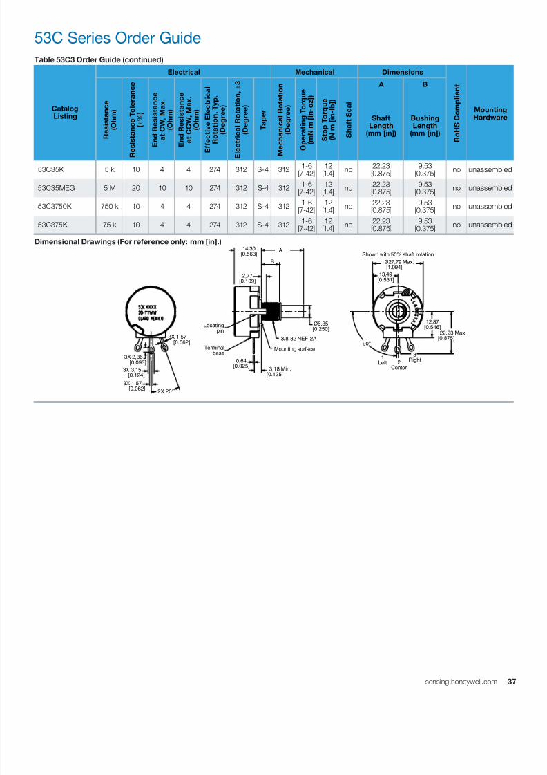
7/23/2019 Honeywell Sensing Potentiometers 380 Rv4 485 53c 385 Datasheet 32301266 a En
http://slidepdf.com/reader/full/honeywell-sensing-potentiometers-380-rv4-485-53c-385-datasheet-32301266-a-en 37/47
3sensing.honeywell.com
Table 53C3 Order Guide (continued)
CatalogListing
Electrical Mechanical Dimensions
R o
H S C o m p
l i a n
t
MountingHardware
R
e s
i s t a n c e
( O h m
)
R e s
i s t a n c e
T o
l e r a n c e
( ± % )
E n d
R e s
i s t a n c e
a t
C W
, M a x .
( O h m
)
E n d
R e s
i s t a n c e
a t C C W
, M a x .
( O h m
)
E f f e c t i v e
E l e c
t r i c a
l
R o t a t i o n ,
T y p .
( D e g r e e
)
E l e c
t r i c
a l R o
t a t i o n , ±
3
( D e g r e e
)
T a p e r
M e c h a
n i c a
l R o
t a t i o n
( D e g r e e
)
O p e r
a t i n g
T o r q u e
( m N m
[ i n - o z
] )
S t
o p
T o r q u e
( N
m
[ i n - l b
] )
S
h a
f t S e a
l
A B
ShaftLength
(mm [in])
BushingLength
(mm [in])
53C35K 5 k 10 4 4 274 312 S-4 312 1-6[7-42]
12[1.4]
no 22,23
[0.875]9,53
[0.375] no unassembled
53C35MEG 5 M 20 10 10 274 312 S-4 312 1-6[7-42]
12[1.4]
no 22,23
[0.875]9,53
[0.375] no unassembled
53C3750K 750 k 10 4 4 274 312 S-4 312 1-6[7-42]
12[1.4]
no 22,23
[0.875]9,53
[0.375] no unassembled
53C375K 75 k 10 4 4 274 312 S-4 312 1-6[7-42]
12[1.4]
no 22,23
[0.875]9,53
[0.375] no unassembled
Dimensional Drawings (For reference only: mm [in].)
53C Series Order Guide
2X 20°
3X 1,57 [0.062]
3X 2,36 [0.093]
3X 1,57 [0.062]
3X 3,15 [0.124]
Mounting surface
3/8-32 NEF-2A
Locating pin
Terminal base
ø6,35[0.250]
3,18 Min.[0.125]
0,64[0.025]
A
B
14,30[0.563]
2,77[0.109]
90°
1Left 2
Center
3Right
12,87[0.546] 22,23 Max.
[0.875]
Shown with 50% shaft rotation
ø27,79 Max. [1.094]
13,49[0.531]
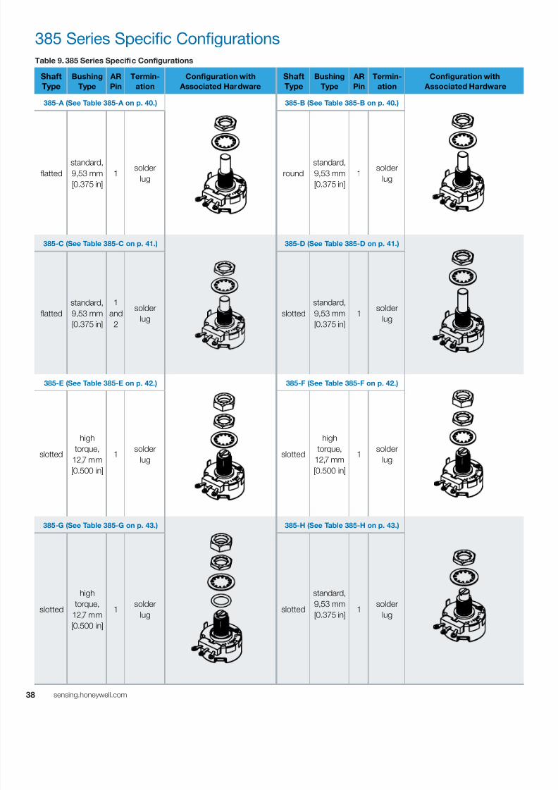
7/23/2019 Honeywell Sensing Potentiometers 380 Rv4 485 53c 385 Datasheet 32301266 a En
http://slidepdf.com/reader/full/honeywell-sensing-potentiometers-380-rv4-485-53c-385-datasheet-32301266-a-en 38/47
38 sensing.honeywell.com
385 Series Specific ConfigurationsTable 9. 385 Series Specific Configurations
Shaft
Type
Bushing
Type
AR
Pin
Termin-
ation
Configuration with
Associated Hardware
Shaft
Type
Bushing
Type
AR
Pin
Termin-
ation
Configuration with
Associated Hardware
385-A (See Table 385-A on p. 40.) 385-B (See Table 385-B on p. 40.)
flatted
standard,
9,53 mm
[0.375 in]
1 solder
lug round
standard,
9,53 mm
[0.375 in]
1 solder
lug
385-C (See Table 385-C on p. 41.) 385-D (See Table 385-D on p. 41.)
flatted
standard,
9,53 mm
[0.375 in]
1
and
2
solder
lugslotted
standard,
9,53 mm
[0.375 in]
1 solder
lug
385-E (See Table 385-E on p. 42.) 385-F (See Table 385-F on p. 42.)
slotted
high
torque,
12,7 mm
[0.500 in]
1 solder
lug slotted
high
torque,
12,7 mm
[0.500 in]
1 solder
lug
385-G (See Table 385-G on p. 43.) 385-H (See Table 385-H on p. 43.)
slotted
high
torque,
12,7 mm
[0.500 in]
1 solder
lug slotted
standard,
9,53 mm
[0.375 in]1
solder
lug
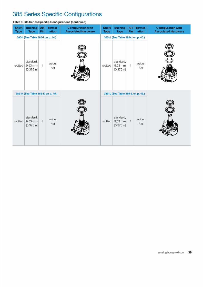
7/23/2019 Honeywell Sensing Potentiometers 380 Rv4 485 53c 385 Datasheet 32301266 a En
http://slidepdf.com/reader/full/honeywell-sensing-potentiometers-380-rv4-485-53c-385-datasheet-32301266-a-en 39/47
3sensing.honeywell.com
Table 9. 385 Series Specific Configurations (continued)
Shaft
Type
Bushing
Type
AR
Pin
Termin-
ation
Configuration with
Associated Hardware
Shaft
Type
Bushing
Type
AR
Pin
Termin-
ation
Configuration with
Associated Hardware
385-I (See Table 385-I on p. 44.) 385-J (See Table 385-J on p. 45.)
slotted
standard,
9,53 mm
[0.375 in]
1 solder
lug slotted
standard,
9,53 mm
[0.375 in]
1 solder
lug
385-K (See Table 385-K on p. 45.) 385-L (See Table 385-L on p. 46.)
slotted
standard,
9,53 mm
[0.375 in]
1 solder
lugslotted
standard,
9,53 mm
[0.375 in]
1 solder
lug
385 Series Specific Configurations

7/23/2019 Honeywell Sensing Potentiometers 380 Rv4 485 53c 385 Datasheet 32301266 a En
http://slidepdf.com/reader/full/honeywell-sensing-potentiometers-380-rv4-485-53c-385-datasheet-32301266-a-en 40/47
40 sensing.honeywell.com
385 Series Order Guides
Table 385-A Order Guide
CatalogListing
Electrical Mechanical Dimensions
R o
H S C o m p
l i a n
t
MountingHardware
R
e s
i s t a n c e
( O h m
)
R e s
i s t a n c e
T o
l e r a n c e
( ± % )
E n d
R e s
i s t a n c e
a t
C W
, M a x .
( O h m
)
E n d
R e s
i s t a n c e
a t C C W
, M a x .
( O h m
)
E f f e c t i v e
E l e c
t r i c a
l
R o t a t i o n ,
T y p .
( D e g r e e
)
E l e c
t r i c
a l R o
t a t i o n , ±
3
( D e g r e e
)
T a p e r
M e c h a
n i c a
l R o
t a t i o n
( D e g r e e
)
O p e r
a t i n g
T o r q u e
( m N m
[ i n - o z
] )
S t
o p
T o r q u e
( N
m
[ i n - l b
] )
S
h a
f t S e a
l
A B C D
F l a t L e n g
t h
( m
m
[ i n ] )
F l a t T
h i c k n e s s
( m
m
[ i n ] )
S h a f t L e n g
t h
( m
m
[ i n ] )
B u s h
i n g
L e n g
t h
( m
m
[ i n ] )
385000M5783 10 k 10 4 4 274 312 S-4 312 1-4[7-28]
12[1.4]
no 12,27[0.483]
5,53[0.218]
22,23[0.875]
9,53[0.375]
yes unassembled
385000M9136 5 k 10 4 4 274 312 S-4 312 1-4[7-28]
12[1.4]
no 9,53[0.375]
3,96[0.156]
22,23[0.875]
9,53[0.375]
yes unassembled
Dimensional Drawings (For reference only: mm [in].)
Table 385-B Order Guide
CatalogListing
Electrical Mechanical Dimensions
R o
H S C o m p
l i a n
t
MountingHardware
R e s
i s t a n c e
( O h m
)
R e s
i s t a n c e
T o l e r a n c e
( ± % )
E n
d R e s
i s t a n
c e
a t C W
, M a x
.
( O h m
)
E n
d R e s
i s t a n
c e
a t C C W
, M a x .
( O h m
)
E f f e c
t i v e
E l e c t r i c a
l
R o
t a t i o n ,
T y p .
( D e g r e e )
E l e c
t r i c a
l R o
t a t i o n , ±
3
( D e g r e e )
T a p e r
M e c
h a n
i c a
l R o t a
t i o n
( D e g r e e )
O p e r a
t i n g
T o r q u e
( m N m
[ i n - o z
] )
S t o p
T o r q u e
( N m
[ i n - l b ]
)
S h a
f t S e a l
A B C D
F l a t L e n g
t h
( m m
[ i n ] )
F l a t T h i c k n e s s
( m m
[ i n ] )
S h a
f t L e n g
t h
( m m
[ i n ] )
B u s
h i n g
L e n g t
h
( m m
[ i n ] )
385500M0012 100 k 10 4 4 274 312 S-4 312 1-4[7-28]
12[1.4]
no 9,53[0.375]
5,53[0.218]
22,23[0.875]
9,53[0.375]
no unassembled
385500M4863 1 k 10 4 4 274 312 S-4 312 1-4[7-28]
12[1.4]
no 9,53[0.375]
5,53[0.218]
22,23[0.875]
9,53[0.375]
no unassembled
385500M5694 5 k 10 4 4 274 312 S-4 312 1-4[7-28]
12[1.4]
no 9,53[0.375]
5,53[0.218]
22,23[0.875]
9,53[0.375]
no unassembled
Dimensional Drawings (For reference only: mm [in].)
2X 20°
3X 1,57 [0.062]
3X 2,36 [0.093]
3X 1,57 [0.062]
3X 3,15 [0.124]
Mounting surface
3/8-32 NEF-2A
3,18 Min.[0.125]
Locating pin
Terminal base
0,635[0.025]
12,87[0.546]
22,23 Max.[0.875]90°
1Left 2
Center
3Right
B
ø6,35 [0.250]
A
C
D
2,77[0.109]
14,30[0.563] Shown with 50% shaft rotation
ø27,79 Max. [1.094]
13,49[0.531]
3,18[0.125]
2X 20°
3X 1,57 [0.062]
3X 2,36 [0.093]
3X 1,57 [0.062]
3X 3,15 [0.124]
90°
1Left 2
Center
3Right
B
ø6,35[0.250]
Mounting surface
3/8-32 NEF-2A
3,18 Min.[0.125]
Locating pin
Terminal base
0,635[0.025]
A
C
D
2,77[0.109]
14,30[0.563]
Shown with 50% shaft rotation
ø27,79 Max. [1.094]
13,49[0.531]
3,18[0.125]
12,87[0.546]
22,23 Max.[0.875]
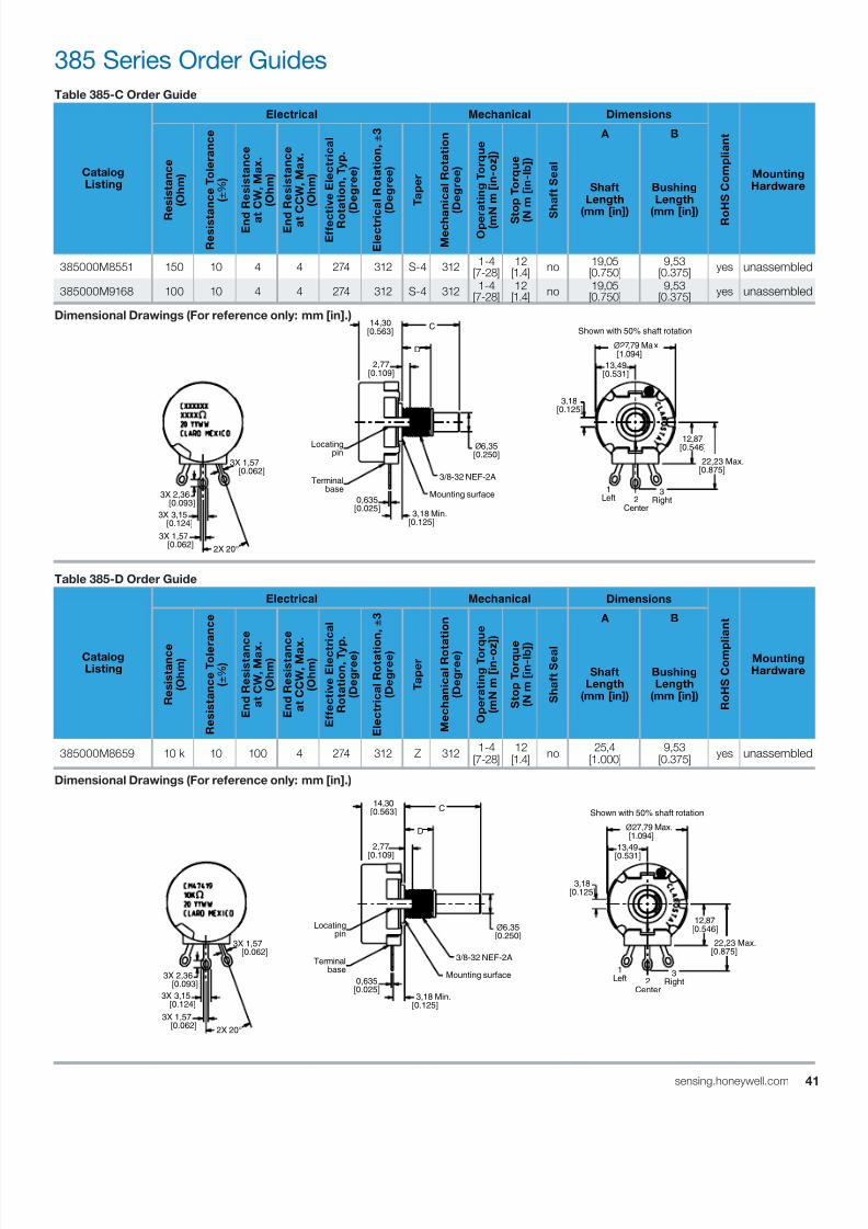
7/23/2019 Honeywell Sensing Potentiometers 380 Rv4 485 53c 385 Datasheet 32301266 a En
http://slidepdf.com/reader/full/honeywell-sensing-potentiometers-380-rv4-485-53c-385-datasheet-32301266-a-en 41/47
4sensing.honeywell.com
385 Series Order Guides
Table 385-C Order Guide
CatalogListing
Electrical Mechanical Dimensions
R o
H S C o m p
l i a n
t
MountingHardware
R
e s
i s t a n c e
( O h m
)
R e s
i s t a n c e
T o
l e r a n c e
( ± % )
E n d
R e s
i s t a n c e
a t
C W
, M a x .
( O h m
)
E n d
R e s
i s t a n c e
a t C C W
, M a x .
( O h m
)
E f f e c t i v e
E l e c
t r i c a
l
R o t a t i o n ,
T y p .
( D e g r e e
)
E l e c
t r i c
a l R o
t a t i o n , ±
3
( D e g r e e
)
T a p e r
M e c h a
n i c a
l R o
t a t i o n
( D e g r e e
)
O p e r
a t i n g
T o r q u e
( m N m
[ i n - o z
] )
S t
o p
T o r q u e
( N
m
[ i n - l b
] )
S
h a
f t S e a
l
A B
ShaftLength
(mm [in])
BushingLength
(mm [in])
385000M8551 150 10 4 4 274 312 S-4 312 1-4[7-28]
12[1.4]
no 19,05
[0.750]9,53
[0.375] yes unassembled
385000M9168 100 10 4 4 274 312 S-4 312 1-4[7-28]
12[1.4]
no 19,05
[0.750]9,53
[0.375] yes unassembled
Dimensional Drawings (For reference only: mm [in].)
Table 385-D Order Guide
CatalogListing
Electrical Mechanical Dimensions
R o
H S C o m p
l i a n
t
MountingHardware
R e s
i s t a n c e
( O h m
)
R e s
i s t a n c e
T o
l e r a n c e
( ± % )
E n
d R e s
i s t a n c e
a t C W
, M a x .
( O h m
)
E n
d R e s
i s t a n c e
a t C C W
, M a x
.
( O h m
)
E f f e c
t i v e
E l e c t r
i c a
l
R o
t a t i o n ,
T y p
.
( D e g r e e )
E l e c
t r i c a
l R o
t a t i o
n , ±
3
( D e g r e e )
T a p e r
M e c
h a n
i c a
l R o t a
t i o n
( D e g r e e )
O p e r a
t i n g
T o r q
u e
( m N m
[ i n - o z
] )
S t o p
T o r q u e
( N m
[ i n - l b ]
)
S h a
f t S e a l
A B
ShaftLength
(mm [in])
BushingLength
(mm [in])
385000M8659 10 k 10 100 4 274 312 Z 312 1-4[7-28]
12[1.4]
no 25,4
[1.000]9,53
[0.375] yes unassembled
Dimensional Drawings (For reference only: mm [in].)
2X 20°
3X 1,57 [0.062]
3X 2,36 [0.093]
3X 1,57 [0.062]
3X 3,15 [0.124]
Mounting surface
3/8-32 NEF-2A
3,18 Min.[0.125]
Locating pin
Terminal base
0,635[0.025]
12,87[0.546]
22,23 Max.[0.875]
1Left 2
Center
3Right
ø6,35[0.250]
C
D
2,77[0.109]
14,30[0.563] Shown with 50% shaft rotation
ø27,79 Max. [1.094]
13,49[0.531]
3,18[0.125]
2X 20°
3X 1,57 [0.062]
3X 2,36 [0.093]
3X 1,57 [0.062]
3X 3,15 [0.124]
Mounting surface
3/8-32 NEF-2A
3,18 Min.[0.125]
Locating pin
Terminal base
0,635[0.025]
12,87[0.546]
22,23 Max.[0.875]
1Left 2
Center
3Right
ø6,35[0.250]
C
D
2,77[0.109]
14,30[0.563] Shown with 50% shaft rotation
ø27,79 Max. [1.094]
13,49[0.531]
3,18[0.125]
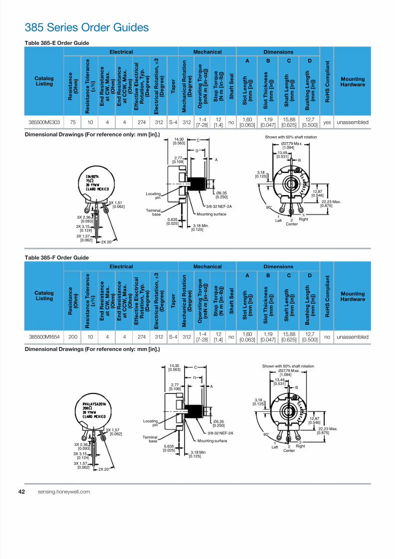
7/23/2019 Honeywell Sensing Potentiometers 380 Rv4 485 53c 385 Datasheet 32301266 a En
http://slidepdf.com/reader/full/honeywell-sensing-potentiometers-380-rv4-485-53c-385-datasheet-32301266-a-en 42/47
42 sensing.honeywell.com
385 Series Order GuidesTable 385-E Order Guide
CatalogListing
Electrical Mechanical Dimensions
R o
H S C o m p
l i a n
t
MountingHardware
R
e s
i s t a n c e
( O h m
)
R e s
i s t a n c e
T o
l e r a n c e
( ± % )
E n d
R e s
i s t a n c e
a t
C W
, M a x .
( O h m
)
E n d
R e s
i s t a n c e
a t C C W
, M a x .
( O h m
)
E f f e c t i v e
E l e c
t r i c a
l
R o t a t i o n ,
T y p .
( D e g r e e
)
E l e c
t r i c a
l R o
t a t i o n , ±
3
( D e g r e e
)
T a p e r
M e c h a
n i c a
l R o
t a t i o n
( D e g r e e
)
O p e r
a t i n g
T o r q u e
( m N m
[ i n - o z
] )
S t
o p
T o r q u e
( N
m [ i n - l b
] )
S
h a
f t S e a
l
A B C D
S l o t L e n g
t h
( m
m
[ i n ] )
S l o t T h i c k n e s s
( m
m
[ i n ] )
S h a f t L e n g
t h
( m
m
[ i n ] )
B u s h
i n g
L e n g
t h
( m
m
[ i n ] )
385500M9303 75 10 4 4 274 312 S-4 312 1-4[7-28]
12[1.4]
no 1,60[0.063]
1,19[0.047]
15,88[0.625]
12,7[0.500]
yes unassembled
Dimensional Drawings (For reference only: mm [in].)
Table 385-F Order Guide
CatalogListing
Electrical Mechanical Dimensions
R o
H S C o m
p l i a n
t
MountingHardware
R e s
i s t a n c e
( O h m )
R e s
i s t a n c e
T o
l e r a n c e
( ± % )
E n
d R e s
i s t a n c e
a t C W
, M a x .
( O h m )
E n
d R e s
i s t a n c e
a t C C W
, M
a x .
( O h m )
E f f e c
t i v e
E l e c
t r i c a
l
R o
t a t i o n ,
T y p .
( D e g r e e
)
E l e c
t r i c a
l R o t a
t i o n , ±
3
( D e g r e e
)
T a p e r
M e c
h a n
i c a
l R o
t a t i o n
( D e g r e e
)
O p e r a
t i n g T o r q u e
( m N m
[ i n -
o z
] )
S t o p
T o r q
u e
( N m
[ i n - l b ] )
S h a
f t S e
a l
A B C D
S l o t L e n g t
h
( m m
[ i n ] )
S l o t T h i c k n e
s s
( m m
[ i n ] )
S h a
f t L e n g t
h
( m m
[ i n ] )
B u s
h i n g
L e n g
t h
( m m
[ i n ] )
385500M1654 200 10 4 4 274 312 S-4 312 1-4[7-28]
12[1.4]
no 1,60[0.063]
1,19[0.047]
15,88[0.625]
12,7[0.500]
no unassembled
Dimensional Drawings (For reference only: mm [in].)
2X 20°
3X 1,57 [0.062]
3X 2,36 [0.093]
3X 1,57 [0.062]
3X 3,15 [0.124]
Mounting surface
3/8-32 NEF-2A
3,18 Min.[0.125]
Locating pin
Terminal base
0,635[0.025]
12,87
[0.546] 22,23 Max.
[0.875]90°
1Left 2
Center
3Right
ø6,35[0.250]
A
C
D
2,77[0.109]
14,30[0.563]
3,18[0.125]
Shown with 50% shaft rotation
ø27,79 Max. [1.094]
13,49[0.531]
B
2X 20°
3X 1,57 [0.062]
3X 2,36 [0.093]
3X 1,57 [0.062]
3X 3,15 [0.124]
Mounting surface
3/8-32 NEF-2A
3,18 Min.[0.125]
Locating pin
Terminal base
0,635[0.025]
12,87[0.546]
22,23 Max.[0.875]90°
1Left 2
Center
3Right
ø6,35[0.250]
A
C
D
2,77[0.109]
14,30[0.563]
Shown with 50% shaft rotation ø27,79 Max.
[1.094]
13,49[0.531]
3,18[0.125]
B

7/23/2019 Honeywell Sensing Potentiometers 380 Rv4 485 53c 385 Datasheet 32301266 a En
http://slidepdf.com/reader/full/honeywell-sensing-potentiometers-380-rv4-485-53c-385-datasheet-32301266-a-en 43/47
4sensing.honeywell.com
385 Series Order GuidesTable 385-G Order Guide
CatalogListing
Electrical Mechanical Dimensions
R o
H S C o m p
l i a n
t
MountingHardware
R
e s
i s t a n c e
( O h m
)
R e s
i s t a n c e
T o
l e r a n c e
( ± % )
E n d
R e s
i s t a n c e
a t
C W
, M a x .
( O h m
)
E n d
R e s
i s t a n c e
a t C C W
, M a x .
( O h m
)
E f f e c t i v e
E l e c
t r i c a
l
R o
t a t i o n ,
T y p .
( D e g r e e
)
E l e c
t r i c a
l R o
t a t i o n , ±
3
( D e g r e e
)
T a p e r
M e c h a
n i c a
l R o
t a t i o n
( D e g r e e
)
O p e r a
t i n g
T o r q u e
( m N m
[ i n - o z
] )
S t
o p
T o r q u e
( N
m [ i n - l b
] )
S
h a
f t S e a
l
A B C D
S l o
t L e n g
t h
( m
m
[ i n ] )
S l o t T h i c k n e s s
( m
m
[ i n ] )
S h a f t L e n g
t h
( m
m
[ i n ] )
B u s h
i n g
L e n g
t h
( m
m
[ i n ] )
385518M0018 5 k 10 4 4 274 312 S-4 312 1-6[7-42]
24[2.8]
yes 1,60[0.063]
1,19[0.047]
15,88[0.625]
12,7[0.500]
no unassembled
Dimensional Drawings (For reference only: mm [in].)
Table 385-H Order Guide
CatalogListing
Electrical Mechanical Dimensions
R o
H S C o m
p l i a n
t
MountingHardware
R e s
i s t a n c e
( O h m )
R e s
i s t a n c e
T o
l e r a n c e
( ± % )
E n
d R e s
i s t a n c e
a t C W
, M a x .
( O h m )
E n
d R e s
i s t a n c e
a t C C W
, M
a x .
( O h m )
E f f e c
t i v e
E l e c
t r i c a
l
R o
t a t i o n ,
T y p .
( D e g r e e
)
E l e c
t r i c a
l R o t a
t i o n , ±
3
( D e g r e e
)
T a p e r
M e c
h a n
i c a
l R o
t a t i o n
( D e g r e e
)
O p e r a
t i n g T o r q u e
( m N m
[ i n -
o z
] )
S t o p
T o r q
u e
( N m
[ i n - l b ] )
S h a
f t S e
a l
A B C D
S l o t L e n g t
h
( m m
[ i n ] )
S l o t T h i c k n e
s s
( m m
[ i n ] )
S h a
f t L e n g t
h
( m m
[ i n ] )
B u s
h i n g
L e n g
t h
( m m
[ i n ] )
385000M1495 5 M 10 4 4 274 312 S-4 312 1-4[7-28]
12[1.4]
no 1,60[0.063]
1,19[0.047]
15,88[0.625]
9,53[0.375]
yes unassembled
385000M6960 270 10 4 4 274 312 S-4 312 1-4[7-28]
12[1.4]
no 1,60[0.063]
1,19[0.047]
22,23[0.875]
9,53[0.375]
yes unassembled
Dimensional Drawings (For reference only: mm [in].)
2X 20°
3X 1,57 [0.062]
3X 2,36 [0.093]
3X 1,57 [0.062]
3X 3,15 [0.124]
Mounting surface
3/8-32 NEF-2A
3,18 Min.[0.125]
Locating pin
Terminal base
0,635[0.025]
12,87
[0.546] 22,23Max.
[0.875]
ø6,35[0.250]
90°
1Left 2
Center
3Right
A
C
D
2,77[0.109]
14,30[0.563] ø27,79 Max.
[1.094]
13,49[0.531]
3,18[0.125]
Shown with 50% shaft rotation
2X 20°
3X 1,57 [0.062]
3X 2,36 [0.093]
3X 1,57 [0.062]
3X 3,15 [0.124]
Mounting surface
3/8-32 NEF-2A
3,18 Min.[0.125]
Locating pin
Terminal base
0,635[0.025]
12,87[0.546]
22,23 Max.[0.875]
90°
1Left 2
Center
3Right
ø6,35[0.250]
A
C
D
2,77[0.109]
14,30[0.563]
Shown with 50% shaft rotation
ø27,79 Max. [1.094]
13,49
[0.531]
3,18[0.125]
B

7/23/2019 Honeywell Sensing Potentiometers 380 Rv4 485 53c 385 Datasheet 32301266 a En
http://slidepdf.com/reader/full/honeywell-sensing-potentiometers-380-rv4-485-53c-385-datasheet-32301266-a-en 44/47
44 sensing.honeywell.com
385 Series Order GuidesTable 385-I Order Guide
CatalogListing
Electrical Mechanical Dimensions
R o
H S C o m p
l i a n
t
MountingHardware
R
e s
i s t a n c e
( O h m
)
R e s
i s t a n c e
T o
l e r a n c e
( ± % )
E n d
R e s
i s t a n c e
a t
C W
, M a x .
( O h m
)
E n d
R e s
i s t a n c e
a t
C C W
, M a x .
( O h m
)
E f f e c
t i v e
E l e c
t r i c a
l
R o
t a t i o n ,
T y p .
( D e g r e e
)
E l e c
t r i c a
l R o
t a t i o n , ±
3
( D e g r e e
)
T a p e r
M e c h a
n i c a
l R o
t a t i o n
( D e g r e e
)
O p e r a
t i n g
T o r q u e
( m N m
[ i n - o z
] )
S t
o p
T o r q u e
( N
m
[ i n - l b
] )
S
h a
f t S e a
l
A B C D
S l o
t L e n g
t h
( m
m
[ i n ] )
S l o t T h i c k n e s s
( m
m
[ i n ] )
S h a f t L e n g
t h
( m
m
[ i n ] )
B u s h
i n g
L e n g
t h
( m
m
[ i n ] )
385500M0297 10 k 10 4 4 274 312 S-4 312 1-4[7-28]
12[1.4] no 1,60
[0.063]1,19
[0.047]22,23[0.875]
9,53[0.375] no unassembled
385500M0567 1 k 10 4 4 274 312 S-4 312 1-4[7-28]
12[1.4] no 1,60
[0.063]1,19
[0.047]22,23[0.875]
9,53[0.375] no unassembled
385500M0563 1 k 10 4 4 274 312 S-4 312 1-4[7-28]
12[1.4] no 1,60
[0.063]1,19
[0.047]31,75[1.25]
9,53[0.375] no unassembled
385500M1231 200 10 4 4 274 312 S-4 312 1-4[7-28]
12[1.4] no 1,60
[0.063]1,19
[0.047]22,23[0.875]
9,53[0.375] no unassembled
385500M1377 500 10 4 4 274 312 S-4 312 1-4[7-28]
12[1.4] no 1,60
[0.063]1,19
[0.047]22,23[0.875]
9,53[0.375] no unassembled
Dimensional Drawings (For reference only: mm [in].)
2X 20°
3X 1,57 [0.062]
3X 2,36 [0.093]
3X 1,57
[0.062]
3X 3,15 [0.124]
Mounting surface
3/8-32 NEF-2A
3,18 Min.[0.125]
Locating pin
Terminal base
0,635[0.025]
12,87[0.546]
22,23 Max.[0.875]90°
1Left 2
Center
3Right
ø6,35 [0.250]
A
C
D
2,77[0.109]
14,30
[0.563]
Shown with 50% shaft rotation
ø27,79 Max. [1.094]
13,49[0.531]
3,18[0.125]
B
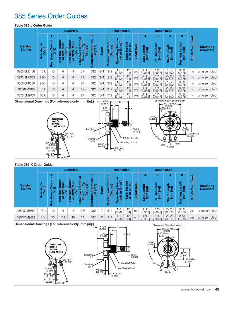
7/23/2019 Honeywell Sensing Potentiometers 380 Rv4 485 53c 385 Datasheet 32301266 a En
http://slidepdf.com/reader/full/honeywell-sensing-potentiometers-380-rv4-485-53c-385-datasheet-32301266-a-en 45/47
4sensing.honeywell.com
385 Series Order Guides
Table 385-K Order Guide
CatalogListing
Electrical Mechanical Dimensions
R o
H S C o m p
l i a n
t
MountingHardware
R e s
i s t a n c e
( O h m
)
R e s
i s t a n c e
T o
l e r a n c e
( ± % )
E n
d R e s
i s t a n c e
a t C W
, M a x .
( O h m
)
E n
d R e s
i s t a n c e
a t C C W
, M a x .
( O h m
)
E f f e c
t i v e
E l e c
t r i c a
l
R o
t a t i o n ,
T y p .
( D e g r e e
)
E l e c
t r i c a
l R o
t a t i o n , ±
3
( D e g r e e
)
T a p e r
M e c
h a n
i c a
l R o
t a t i o n
( D e g r e e
)
O p e r a
t i n g
T o r q u e
( m N m
[ i n - o z
] )
S t o p
T o r q u e
( N m
[ i n - l b
] )
S h a
f t S e a
l
A B C D
S l o t L e n g
t h
( m m
[ i n ] )
S l o t T h i c k n e s s
( m m
[ i n ] )
S h a
f t L e n g
t h
( m m
[ i n ] )
B u s
h i n g
L e n g
t h
( m m
[ i n ] )
385000M8686 100 k 10 4 4 274 312 Z 312 1-4[7-28]
12[1.4]
no 1,60[0.063]
1,19[0.047]
22,23[0.875]
9,53[0.375]
yes unassembled
385500M9553 1 M 20 10 k 10 274 312 Z 312 1-4[7-28]
12[1.4]
no 1,60[0.063]
1,19[0.047]
22,23[0.875]
9,53[0.375]
yes unassembled
Dimensional Drawings (For reference only: mm [in].)
Table 385-J Order Guide
CatalogListing
Electrical Mechanical Dimensions
R o
H S C o m p
l i a n
t
MountingHardware
R e s
i s t a n c e
( O h m
)
R e s
i s t a
n c e
T o
l e r a n c e
( ± % )
E n d
R e s
i s t a n c e
a t
C W
, M a x .
( O h m
)
E n d
R e s
i s t a n c e
a t C C W
, M a x .
( O h m
)
E f f e c t i v e
E l e c
t r i c a
l
R o t a t i o n ,
T y p .
( D e g r e e
)
E l e c
t r i c
a l R o
t a t i o n , ±
3
( D e g r e e
)
T a p e r
M e c h a
n i c a
l R o
t a t i o n
( D e g r e e
)
O p e r
a t i n g
T o r q u e
( m N
m
[ i n - o z
] )
S t o p
T o r q u e
( N
m
[ i n - l b
] )
S
h a
f t S e a
l
A B C D
S l o t L e n g
t h
( m
m
[ i n ] )
S l o t T
h i c k n e s s
( m
m
[ i n ] )
S h a f t L e n g
t h
( m
m
[ i n ] )
B u s h
i n g
L e n g
t h
( m
m
[ i n ] )
385518M0106 10 k 10 4 4 274 312 S-4 312 1-6[7-42]
12[1.4] yes 1,60
[0.063]1,19
[0.047]12,7
[0.500]9,53
[0.375] no unassembled
385518M0869 2.5 k 10 4 4 274 312 S-4 312 1-6[7-42]
12[1.4] yes 1,60
[0.063]1,19
[0.047]22,23[0.875]
9,53[0.375] no unassembled
385518M1309 2.5 k 10 4 4 274 312 S-4 312 1-6[7-42]
12[1.4] yes 1,60
[0.063]1,19
[0.047]12,7
[0.500]9,53
[0.375] no unassembled
385518M1813 10 k 10 4 4 274 312 S-4 312 1-6[7-42]
12[1.4] yes 1,60
[0.063]1,19
[0.047]22,23[0.875]
9,53[0.375] no unassembled
385518M2059 50 k 10 4 4 274 312 S-4 312 1-6[7-42]
12[1.4] yes 1,60
[0.063]1,19
[0.047]12,7
[0.500]9,53
[0.375] no unassembled
Dimensional Drawings (For reference only: mm [in].)
2X 20°
3X 1,57 [0.062]
3X 2,36 [0.093]
3X 1,57 [0.062]
3X 3,15 [0.124]
Mounting surface
3/8-32 NEF-2A
3,18 Min.[0.125]
Locating pin
Terminal base
0,635[0.025]
12,87[0.546]
22,23 Max.[0.875]
90°
1Left 2
Center
3Right
ø6,35 [0.250]
A
C
D2,77
[0.109]
14,30[0.563]
3,18[0.125]
Shown with 50% shaft rotation
ø27,79 Max. [1.094]
13,49[0.531]
B
2X 20°
3X 1,57 [0.062]
3X 2,36 [0.093]
3X 1,57 [0.062]
3X 3,15 [0.124]
Mounting surface
3/8-32 NEF-2A
3,18 Min.[0.125]
Locating pin
Terminal base
0,635[0.025]
12,87[0.546]
22,23 Max.[0.875]90°
1Left 2
Center
3Right
ø6,35 [0.250]
A
C
D2,77
[0.109]
14,30[0.563]
3,18[0.125]
Shown with 50% shaft rotation
ø27,79 Max.
[1.094]13,49
[0.531]B
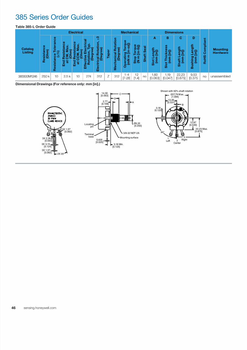
7/23/2019 Honeywell Sensing Potentiometers 380 Rv4 485 53c 385 Datasheet 32301266 a En
http://slidepdf.com/reader/full/honeywell-sensing-potentiometers-380-rv4-485-53c-385-datasheet-32301266-a-en 46/47
46 sensing.honeywell.com
385 Series Order GuidesTable 385-L Order Guide
CatalogListing
Electrical Mechanical Dimensions
R o
H S C o m p
l i a n
t
MountingHardware
R
e s
i s t a n c e
( O h m
)
R e s
i s t a n c e
T o
l e r a n c e
( ± % )
E n d
R e s
i s t a n c e
a t
C W
, M a x .
( O h m
)
E n d
R e s
i s t a n c e
a t C C W
, M a x .
( O h m
)
E f f e c t i v e
E l e c
t r i c a
l
R o
t a t i o n ,
T y p .
( D e g r e e
)
E l e c
t r i c a
l R o
t a t i o n , ±
3
( D e g r e e
)
T a p e r
M e c h a
n i c a
l R o
t a t i o n
( D e g r e e
)
O p e r a
t i n g
T o r q u e
( m N m
[ i n - o z
] )
S t
o p
T o r q u e
( N
m [ i n - l b
] )
S
h a
f t S e a
l
A B C D
S l o
t L e n g
t h
( m
m
[ i n ] )
S l o t T h i c k n e s s
( m
m
[ i n ] )
S h a f t L e n g
t h
( m
m
[ i n ] )
B u s h
i n g
L e n g
t h
( m
m
[ i n ] )
385500M1246 250 k 10 2.5 k 10 274 312 Z 312 1-4[7-28]
12[1.4]
no 1,60[0.063]
1,19[0.047]
22,23[0.875]
9,53[0.375]
no unassembled
Dimensional Drawings (For reference only: mm [in].)
2X 20°
3X 1,57 [0.062]
3X 2,36 [0.093]
3X 1,57 [0.062]
3X 3,15 [0.124]
Mounting surface
3/8-32 NEF-2A
3,18 Min.[0.125]
Locating pin
Terminal base
0,635[0.025]
12,87[0.546]
22,23 Max.[0.875]90°
1Left 2
Center
3Right
ø6,35 [0.250]
A
C
D2,77
[0.109]
14,30[0.563]
Shown with 50% shaft rotation
ø27,79 Max. [1.094]
13,49[0.531]
3,18[0.125]
B

7/23/2019 Honeywell Sensing Potentiometers 380 Rv4 485 53c 385 Datasheet 32301266 a En
http://slidepdf.com/reader/full/honeywell-sensing-potentiometers-380-rv4-485-53c-385-datasheet-32301266-a-en 47/47
Find out more
Honeywell serves its customers
through a worldwide network
of sales offices, representatives
and distributors. For application
assistance, current specifications,
pricing or name of the nearest
Authorized Distributor, contact
your local sales office.
To learn more about Honeywell’s
sensing and control products,
call +1-815-235-6847 or
1-800-537-6945,
visit sensing.honeywell.com,
or e-mail inquiries to
ADDITIONAL INFORMATION
The following associated literature is available at sensing.honeywell.com:
• Product Range Guide
• Product Line Guide
• Installation Instructions
WARRANTY/REMEDY
Honeywell warrants goods of its manufacture as being free of
defective materials and faulty workmanship. Honeywell’s standard
product warranty applies unless agreed to otherwise by Honeywel
in writing; please refer to your order acknowledgement or consult
your local sales office for specific warranty details. If warranted
goods are returned to Honeywell during the period of coverage,
Honeywell will repair or replace, at its option, without charge
those items it finds defective. The foregoing is buyer’s sole
remedy and is in lieu of all other warranties, expressed or
implied, including those of merchantability and fitness for
a particular purpose. In no event shall Honeywell be liable
for consequential, special, or indirect damages.
While we provide application assistance personally, through our
literature and the Honeywell website, it is up to the customer to
determine the suitability of the product in the application.
Specifications may change without notice. The information we
supply is believed to be accurate and reliable as of this printing.
However, we assume no responsibility for its use.
WARNINGPERSONAL INJURY
DO NOT USE these products as safety or emergency stop
devices or in any other application where failure of the product
could result in personal injury.
Failure to comply with these instructions could result in
death or serious injury.
WARNINGMISUSE OF DOCUMENTATION
• The information presented in this product sheet is for
reference only. Do not use this document as a product
installation guide.
• Complete installation, operation, and maintenance
information is provided in the instructions supplied with each
product.
Failure to comply with these instructions could result in
death or serious injury.


