56
OPERATOR’S MANUAL FERTILIZER SPREADERS SS1023B SS1036B SS1067B SS2036B SS2067B Manual 5BP960376B Date 05/19/2011

O P E R A T O R ’ S M A N U A L
FERTILIZER SPREADERSSS1023BSS1036BSS1067B SS2036BSS2067B
Manual 5BP960376BDate 05/19/2011

Take note! This safety alert symbol found throughout this manual is used to call yourattention to instructions involving your personal safety and the safety of others. Failure tofollow these instructions can result in injury or death.
Signal Words
Note the use of the signal words DANGER, WARNING and CAUTION with the safety messages. Theappropriate signal words for each have been selected using the following guidelines:
DANGER: Indicates an imminently hazardous situation that, if not avoided, will result in death orserious injury.
WARNING: Indicates a potentially hazardous situation that, if not avoided, could result in death orserious injury, and includes hazards that are exposed when guards are removed. It may also be usedto alert against unsafe practices.
CAUTION: Indicates a potentially hazardous situation that, if not avoided, may result in minor ormoderate injury.
SAFETY
This symbol means:
ATTENTION!
BECOME ALERT!
YOUR SAFETY IS INVOLVED!

31PARTS MANUAL
287 - PRE-DELIVERY CHECKLIST
276 - TROUBLESHOOTING
265.02 - Storage
265.01 - Suggested Spare Parts
265 - REPAIR PROCEDURES
234.04 - Transport
224.03 - Driveline
224.02 - Service
214.01 - Maintenance Safety
214 - MAINTENANCE
203.07 - Uneven Terrain
173.06 - Operating Techniques
173.05 - Start Up
163.04 - Attaching to the Tractor
153.03 - Pre-Operational Check
153.02 - Set Up
143.01 - Operational Safety
143 - OPERATION
122.03 - Messages and Signs
112.02 - Starting and Stopping
112.01 - Preparation
112 - SAFETY PRECAUTIONS
81.05 - Assembly Instructions for Models SS1067B & SS2067B
61.04 - Assembly Instructions for Models SS1036B & SS2036B
51.03 - Assembly Instructions for Model SS1023B
41.02 - Model and Serial Number ID
41.01 - General
41 - GENERAL INFORMATION
INDEX
INDEX 3 FRONTIER

1 - GENERAL INFORMATION
Thank you and congratulations for having chosen our implement. Your new fertilizer spreader is atechnologically advanced machine constructed of high quality sturdy components that will fulfill yourworking expectations. Read this manual carefully. It will instruct you on how to operate and serviceyour fertilizer spreader safely and correctly. Failure to do so could result in personal injury and/orequipment damage.
1.01 - General
The implement described in this manual is to be used with tractors with PTO at 540 rpm andclockwise rotation.
CAUTION: Always ensure that the coupling of the implement with the tractor is done at thesame PTO speed and direction of rotation. Do not operate this implement at a PTO speed ordirection of rotation other than that shown on the implement. Serious damage can occur tothe machine and/or the operator.
CAUTION: Unless otherwise specified, all hardware is metric. Use only metric tools on metrichardware. Other tools that do not fit properly can slip and cause injury.
CAUTION: Right hand and left hand sides of the implement are determined by facing in thedirection the implement will travel when going forward (see fig. 6).
Warranty coverage is provided by John Deere according to the terms of the Agricultural/Commercial& Consumer Equipment Warranty Statement. Carefully read the warranty statement on the back ofyour original purchase order for details on coverage and limitations of this warranty.Your Authorized Company Dealer has genuine parts in stock. Only these approved replacement partsshould be used.
1.02 - Model and Serial Number ID
Attached to the hopper is an ID plate showing the model and the serial number. Record yourimplement model and serial number in the space provided below. Your dealer needs this informationto give you prompt, efficient service when you order parts.
FERTILIZER SPREADERS OPERATOR’S MANUAL
GENERAL INFORMATION 4 FRONTIER
1.03 - Assembly Instructions for Model SS1023B
CAUTION: Stand clear of bands when cutting as they could be under sufficient tension tocause them to fly loose. Take care in removing bands and wire. They often have extremelysharp edges and cut very easily.
NOTE: Assembly will be easier if all parts are loosely assembled before tightening the hardware. Allhardware needed for assembly will be found in the hardware bag or on the machine.
Each unit is shipped with a hardware bag that consists of the following:
1Hairpin cotter Ø5 (5BP0041291)3Washer fender Ø8 (5BP0014514)4Washer flat Ø8 (5BP0015230)8Nut HH M08-1.25 C6 Z TK (5BP0001806)1Nut HH M30-2.00 C6 Z TN (5BP501651B)2Bolt HH M08-1.25x16 C8.8 Z F (5BP0046454)3Bolt CR M08-1.25x25 C4.6 Z (5BP501663B)1Threaded bushing (5BP501622B)2Bushing cat.0/1 for tractor arms (5BP0014710); serial #XF...287132 & below only
Hardware bag contains the following:1Driveline1Flow control assembly (#5, fig. 2)1Guard (#4, fig. 2)1Stirrer (#8, fig. 2)1Mobile shutter (#10, fig. 2)1Spreader disc (#11, fig. 2)
Model SS1023B Qty.Description
To assemble the spreader do the following:1. Attach spreader disc (see #11, fig. 2) to output shaft of gearbox securing it with the hairpin cotter
(see #27, fig. 2).2. Install guard (see #4, fig. 2) with scale label facing up to the brackets on the spreader frame.
Attach it to the frame using two M8x16 bolts (see #22, fig. 2), four Ø8 flat washers (see #19, fig.2) and two M8 nuts (see #21, fig. 2).
3. Insert threaded bushing (see #9, fig. 2) through hopper bottom (see #3, fig. 2). Attach mobileshutter (see #10, fig. 2) to threaded bushing and secure with nut (see #26, fig. 2).
4. Slide hopper and onto the output shaft of the gearbox. Secure hopper to frame using three M8x25carriage bolts (see #18, fig. 2), three Ø8 fender washers (see #20, fig. 2), and six M8 hex nuts(see #21, fig. 2).
5. Install flow control assembly (see #5, fig. 2) into slot in mobile shutter at the bottom of the hopper.6. Secure location of the shutter lever by tightening the two knobs (see #6, fig. 2).7. Install the stirrer (see #8, fig. 2) using M8x35 hex bolt (see #24, fig. 2), two Ø8 flat washers (see
#19, fig. 2), and one M8 elastic stop nut (see #25, fig. 2) that are already bolted to the stirrer.8. Tighten all hardware.9. Install driveline and ensure it has at least 2” from bottoming out in its shortest working position and
has the minimum 6” overlap in its longest working position. Refer to Section 4.031 of this manual,if it is determined that the driveline is too long and needs to be shortened. Contact your localdealer if it is determined that the driveline is too short for your tractor.
FERTILIZER SPREADERS OPERATOR’S MANUAL
GENERAL INFORMATION 5 FRONTIER
1 See Section 4.03 - Driveline, for instructions on how to determine correct driveline length and procedures forshortening the driveline.

1.04 - Assembly Instructions for Models SS1036B & SS2036B
Each unit is shipped with a hardware bag that consists of the following:
11Hairpin cotter Ø5 (5BP0041291)22Washer fender Ø10 (5BP0030157)33Washer fender Ø8 (5BP0014514)67Washer flat Ø8 (5BP0015230)23Washer lock Ø8 (5BP0003144)66Nut HH M08-1.25 C6 Z TK (5BP0001806)56Nut HH M08-1.25 C6 Z MD (5BP0046545)22Bolt HH M08-1.25x20 C8.8 Z F (5BP0015012)11Bolt HH M08-1.25x16 C8.8 Z F (5BP0046454)3-Bolt CR M08-1.25x35 C4.6 Z (5BP0014619)-3Bolt CR M08-1.25x25 C4.6 Z (5BP501663B)23Bolt CR M08-1.25x20 C4.6 Z (5BP0084289)22Bushing cat.0/1 for tractor arms (5BP0014710)1-Attachment plate (5BP0014635) (#6, fig. 3)-1Attachment plate (5BP0014338) (#6, fig. 3)
Hardware bag contains the following:11Driveline11Protection (#4, fig. 3)11Stationary stirrer (#20, fig. 3)11Scaled rod assembly (#18, fig. 3)11Lever (#16, fig. 3)11Protection (#5, fig. 3)11Shutter assembly11Spreader disc (#21, fig. 3)
Model SS2036B Qty.Model SS1036B Qty.Description
FERTILIZER SPREADERS OPERATOR’S MANUAL
GENERAL INFORMATION 6 FRONTIER
Fig. 2 - Model SS1023 assembly.
CAUTION: Stand clear of bands when cutting as they could be under sufficient tension tocause them to fly loose. Take care in removing bands and wire. They often have extremelysharp edges and cut very easily.
NOTE: Assembly will be easier if all parts are loosely assembled before tightening the hardware. Allhardware needed for assembly will be found in the hardware bag or on the machine.
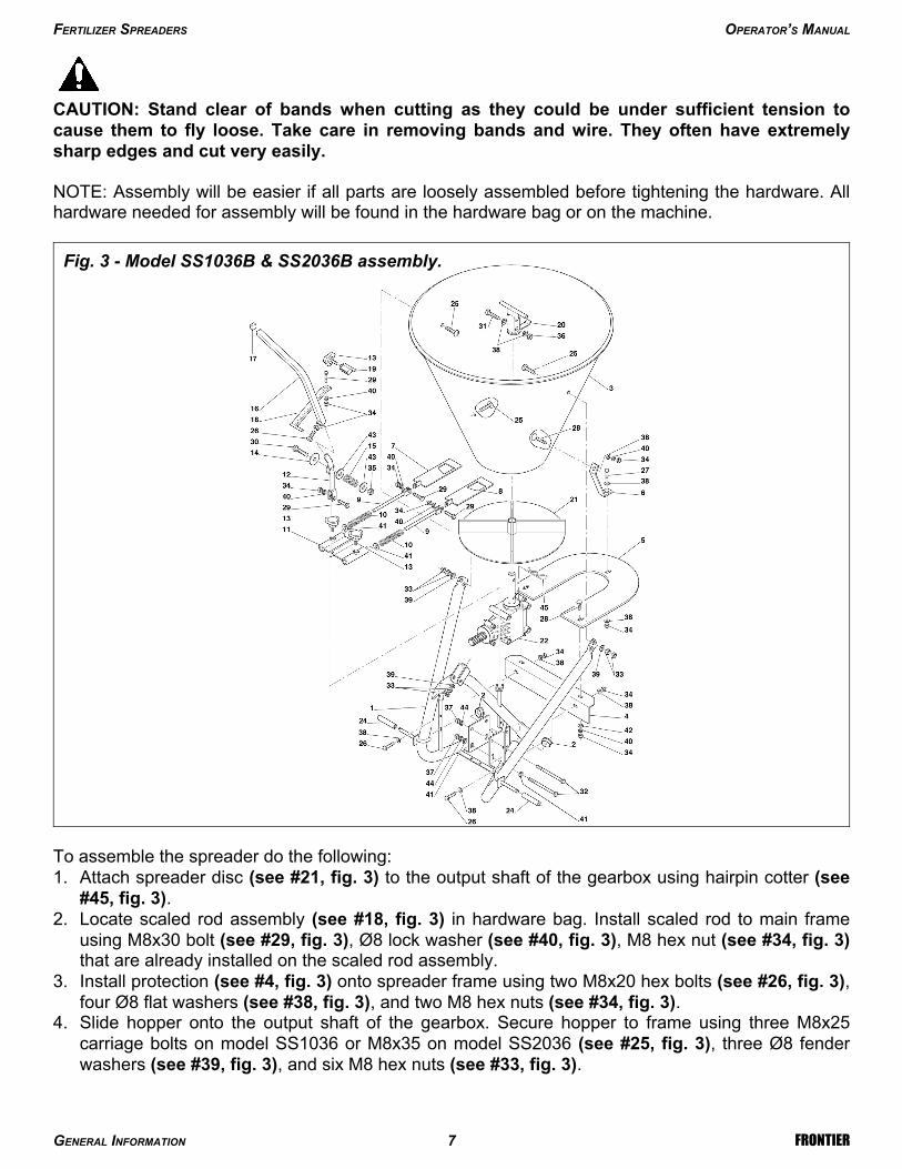
To assemble the spreader do the following:1. Attach spreader disc (see #21, fig. 3) to the output shaft of the gearbox using hairpin cotter (see
#45, fig. 3).2. Locate scaled rod assembly (see #18, fig. 3) in hardware bag. Install scaled rod to main frame
using M8x30 bolt (see #29, fig. 3), Ø8 lock washer (see #40, fig. 3), M8 hex nut (see #34, fig. 3)that are already installed on the scaled rod assembly.
3. Install protection (see #4, fig. 3) onto spreader frame using two M8x20 hex bolts (see #26, fig. 3),four Ø8 flat washers (see #38, fig. 3), and two M8 hex nuts (see #34, fig. 3).
4. Slide hopper onto the output shaft of the gearbox. Secure hopper to frame using three M8x25carriage bolts on model SS1036 or M8x35 on model SS2036 (see #25, fig. 3), three Ø8 fenderwashers (see #39, fig. 3), and six M8 hex nuts (see #33, fig. 3).
FERTILIZER SPREADERS OPERATOR’S MANUAL
GENERAL INFORMATION 7 FRONTIER
Fig. 3 - Model SS1036B & SS2036B assembly.

5. Install the stationary stirrer (see #20, fig. 3) using M8x45 hex bolt (see #31, fig. 3), two Ø8 flatwashers (see #38, fig. 3), and one M8 elastic stop nut (see #36, fig. 3) that are already bolted tothe stirrer.
6. Install protection (see #5, fig. 3) using two M8x20 carriage bolts (see #28, fig. 3), two Ø10 fenderwashers (see #42, fig. 3), two Ø8 lock washers (see #40, fig. 3) and secure with two M8 hex nuts(see #34, fig. 3). Install attachment plate (see #6, fig. 3) on protection using M8x16 hex bolt (see#27, fig. 3), two Ø8 flat washers (see #38, fig. 3) and secure with M8 hex nut (see #34, fig. 3),then install it to the hopper using M8x20 carriage bolt on model SS1036 or M8x25 on modelSS2036 (see #28, fig. 3), on model SS2036 use bolt already installed on hopper, and secure withØ8 flat washer (see #38, fig. 3), Ø8 lock washer (see #40, fig. 3) and a M8 hex bolt (see #34, fig.3).
7. Install shutter assembly found in the hardware bag by sliding shutters (see #7 & #8, fig. 3) into theslots at bottom of the hopper.
8. Assemble shutter guide plate (see #11, fig. 3) to lever bracket (see #12, fig. 3), which is alreadyinstalled on the frame using M8x30 hex bolt (see #29, fig. 3), Ø8 lock washer (see #40, fig. 3),and M8 hex nut (see #34, fig. 3).
9. Install lever (see #16, fig. 3) to lever bracket using one M8x20 hex bolt (see #26, fig. 3) which isshipped installed on the lever. Secure bolt with M8 hex nut (see #34, fig. 3).
10.Tighten all hardware.11. Install driveline and ensure it has at least 2” from bottoming out in its shortest working position and
has the minimum 6” overlap in its longest working position. Refer to Section 4.032 of this manual,if it is determined that the driveline is too long and needs to be shortened. Contact your localdealer if it is determined that the driveline is too short for your tractor.
1.05 - Assembly Instructions for Models SS1067B & SS2067B
Each unit is shipped with a hardware bag that consists of the following:
33Washer flat Ø14 (5BP0091435)1011Washer flat Ø8 (5BP0015230)-1Washer lock Ø8 (5BP0003144)88Washer lock Ø6 (5BP0046536)88Nut HH M06-1.00 C6 Z TK (5BP501603B)56Nut HH M08-1.25 C6 Z MD (5BP0046545)66Nut HH M12-1.75 C6 Z MD (5BP0001106)88Bolt HH M06-1.00x16 C8.8 Z F (5BP0036319)22Bolt HH M08-1.25x20 C8.8 Z F (5BP0015012)33Bolt HH M08-1.25x16 C8.8 Z F (5BP0046454)-1Bolt CR M08-1.25x20 C4.6 Z (5BP0084289)3-Bolt CR M12-1.75x40 C8.8 Z (5BP0044115)-3Bolt CR M12-1.75x30 C4.6 Z (5BP0051073)1-Attachment plate (5BP0014339) (#2, fig. 5)-1Attachment plate (5BP0014338) (#2, fig. 5)
Hardware bag contains the following:11Driveline11Stationary stirrer (#21, fig. 4)44Spreader wings (#20, fig. 4)11Protection (#1, fig. 5)11Protection (#4, fig. 4)11Shutter assembly (#9, fig. 4)11Scaled rod (#17, fig. 4)11Hitch lever (#15, fig. 4) 11Lever (#14, fig. 4)
Model SS2067B Qty.Model SS1067B Qty.Description
FERTILIZER SPREADERS OPERATOR’S MANUAL
GENERAL INFORMATION 8 FRONTIER
2 See Section 4.03 - Driveline, for instructions on how to determine correct driveline length and procedures forshortening the driveline.

CAUTION: Stand clear of bands when cutting as they could be under sufficient tension tocause them to fly loose. Take care in removing bands and wire. They often have extremelysharp edges and cut very easily.
NOTE: Assembly will be easier if all parts are loosely assembled before tightening the hardware. Allhardware needed for assembly will be found in the hardware bag or on the machine.
To assemble the spreader do the following:1. Attach four spreader wings (see #20, fig. 4) to the spreader disc (see #19, fig. 4) with eight
M6x16 hex bolts (see #36, fig. 4), Ø6 lock washers (see #37, fig. 4) and M6 hex nuts (see #38,fig. 4).
2. Locate scaled rod assembly (see #17, fig. 4) in hardware bag. Install scaled rod to main frameusing M8x30 hex bolt (see #29, fig. 4), Ø8 lock washer (see #30, fig. 4) and M8 hex nut (see #28,fig. 4) that are already installed on the scaled rod assembly.
3. Install protection (see #4, fig. 4) on spreader frame using two M8x20 hex bolts (see #26, fig. 4),two Ø8 flat washers (see #27, fig. 4) and two M8 hex nuts (see #28, fig. 4).
4. Slide hopper (see #3, fig. 4) onto the output shaft of the gearbox.
FERTILIZER SPREADERS OPERATOR’S MANUAL
GENERAL INFORMATION 9 FRONTIER
Fig. 4 - Models SS1067B & SS2067B assembly.
5. Secure hopper to frame using three M12x30 carriage bolts on model SS1067B or M12x40 onmodel SS2067B (see #23, fig. 4), three Ø14 flat washers (see #24, fig. 4), and six M12 hex nuts(see #25 fig. 4).
6. Install stationary stirrer (see #21, fig. 4) using M8x45 bolt (see #39, fig. 4), two Ø8 flat washers(see #27, fig. 4), and M8 elastic stop nut (see #40, fig. 4) that are already bolted to the stirrer.
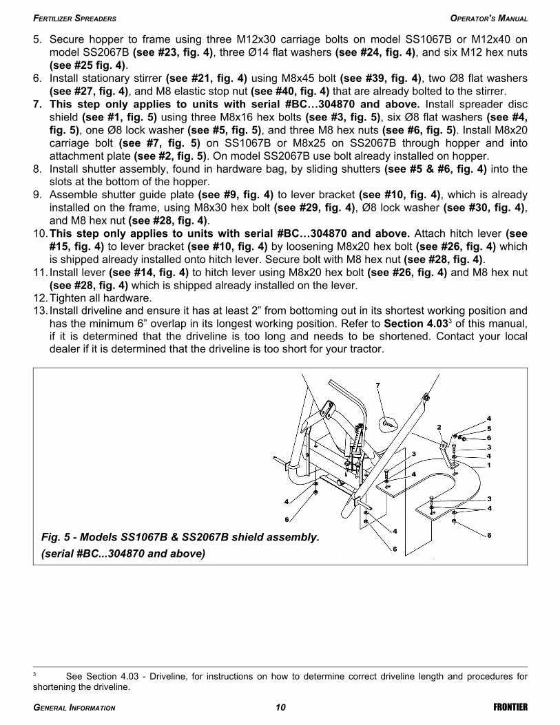
7. This step only applies to units with serial #BC…304870 and above. Install spreader discshield (see #1, fig. 5) using three M8x16 hex bolts (see #3, fig. 5), six Ø8 flat washers (see #4,fig. 5), one Ø8 lock washer (see #5, fig. 5), and three M8 hex nuts (see #6, fig. 5). Install M8x20carriage bolt (see #7, fig. 5) on SS1067B or M8x25 on SS2067B through hopper and intoattachment plate (see #2, fig. 5). On model SS2067B use bolt already installed on hopper.
8. Install shutter assembly, found in hardware bag, by sliding shutters (see #5 & #6, fig. 4) into theslots at the bottom of the hopper.
9. Assemble shutter guide plate (see #9, fig. 4) to lever bracket (see #10, fig. 4), which is alreadyinstalled on the frame, using M8x30 hex bolt (see #29, fig. 4), Ø8 lock washer (see #30, fig. 4),and M8 hex nut (see #28, fig. 4).
10.This step only applies to units with serial #BC…304870 and above. Attach hitch lever (see#15, fig. 4) to lever bracket (see #10, fig. 4) by loosening M8x20 hex bolt (see #26, fig. 4) whichis shipped already installed onto hitch lever. Secure bolt with M8 hex nut (see #28, fig. 4).
11. Install lever (see #14, fig. 4) to hitch lever using M8x20 hex bolt (see #26, fig. 4) and M8 hex nut(see #28, fig. 4) which is shipped already installed on the lever.
12.Tighten all hardware.13. Install driveline and ensure it has at least 2” from bottoming out in its shortest working position and
has the minimum 6” overlap in its longest working position. Refer to Section 4.033 of this manual,if it is determined that the driveline is too long and needs to be shortened. Contact your localdealer if it is determined that the driveline is too short for your tractor.
FERTILIZER SPREADERS OPERATOR’S MANUAL
GENERAL INFORMATION 10 FRONTIER
3 See Section 4.03 - Driveline, for instructions on how to determine correct driveline length and procedures forshortening the driveline.
Fig. 5 - Models SS1067B & SS2067B shield assembly.
(serial #BC...304870 and above)

2 - SAFETY PRECAUTIONS
Safety is the primary concern in the design and manufacture of our products. Unfortunately our effortsto provide safe equipment can be wiped out by a single careless act of an operator.In addition to the design and configuration of equipment, hazard control and accident prevention aredependent upon the awareness, concern, prudence and proper training of personnel involved in theoperation, transport, maintenance and storage of equipment.It is the operator’s responsibility to read and understand all safety and operating instructions in themanual and to follow these.Allow only properly trained personnel to operate the fertilizer spreader. Working with unfamiliarequipment can lead to careless injuries. Read this manual, and the manual for your tractor, beforeassembly or operation, to acquaint yourself with the machines. It is the spreader owner’sresponsibility, if this machine is used by any person other than yourself, is loaned or rented, to makecertain that the operator, prior to operating, reads and understands the operator’s manuals and isinstructed in safe and proper use.
2.01 - Preparation
1. Before operating equipment read and understand the operator’s manual and the safety signs (seefig. 6).
2. Thoroughly inspect the implement before initial operation to assure that all packaging materials,i.e., wires, bands, and tape have been removed.
3. Personal protection equipment including hard hat, safety glasses, safety shoes, and gloves arerecommended during assembly, installation, operation, adjustment, maintaining and/or repairingthe implement.
4. Operate the fertilizer spreader only with a tractor equipped with an approvedRoll-Over-Protective-System (ROPS). Always wear your seat belt. Serious injury or even deathcould result from falling off the tractor.
5. Clear area of stones, branches or other debris that might be thrown, causing injury or damage.6. Operate only in daylight or good artificial light.7. Ensure fertilizer spreader is properly mounted, adjusted and in good operating condition.8. Ensure that all safety shielding and safety signs are properly installed and in good condition.9. Chemicals may cause eye, skin or breathing problems. Always wear a face mask, gloves and
goggles when filling hopper.10.Before loading the fertilizer in the hopper read carefully the instructions printed on the fertilizer
canvas bag concerning the precautions to be taken in case of toxicity or corrosivity of the product.Before loading switch off the engine and remove the ignition key.
11.Load hopper with product only after the spreader has been properly attached to the tractor.
2.02 - Starting and Stopping
1. Be sure that no one is near the machine prior to engaging or while the machine is working.2. Be sure the tractor is in “Neutral” before starting engine.
FERTILIZER SPREADERS OPERATOR’S MANUAL
SAFETY PRECAUTIONS 11 FRONTIER

3. The operating power is supplied from tractor PTO. Refer to your tractor manual for PTOengagement and disengagement instructions. Always operate PTO at 540 rpm. Know how to stopthe tractor and machine quickly in case of an emergency.
4. When engaging PTO, the engine rpm should always be low. Once engaged and ready to startoperating, raise PTO speed to 540 rpm and maintain throughout operation.
5. Check the tractor master shield over the PTO stub shaft. Make sure it is in good condition andfastened securely to the tractor. Purchase a new shield if old shield is damaged or missing.
6. After striking an obstacle, disengage the PTO, shut the tractor down and thoroughly inspect fordamage before restarting.
7. To park the vehicle safely, stop vehicle on a level surface (not on a slope), disengage PTO,engage the parking brake, stop the engine, remove the key, and wait for engine and all movingparts to stop before leaving the operator’s seat.
8. Stay clear of rotating drivelines. Entanglement in rotating driveline can cause serious injury ordeath. Wear close fitting clothing. Stop the engine and be sure PTO driveline is stopped beforegetting near it.
2.03 - Messages and Signs
1. Read and adhere to all safety and operating decals on this machine (see fig. 6).2. Before dismounting tractor: Stop engine, set brake and remove the key of unattended equipment.3. Keep away from rotating parts and driveline.4. Keep guards and shields in place and in good condition.5. Do not use with bystanders in area.6. Allow no riders on tractor or fertilizer spreader.7. Allow moving parts to stop before repair.8. Securely support fertilizer spreader before working underneath.
Additional warning and operating decals are available at no extra charge. Please specify model andserial number when ordering.
Fig. 6 - Safety decals - driveline; replace immediately if damaged.
FERTILIZER SPREADERS OPERATOR’S MANUAL
SAFETY PRECAUTIONS 12 FRONTIER
outer tube
outer shield
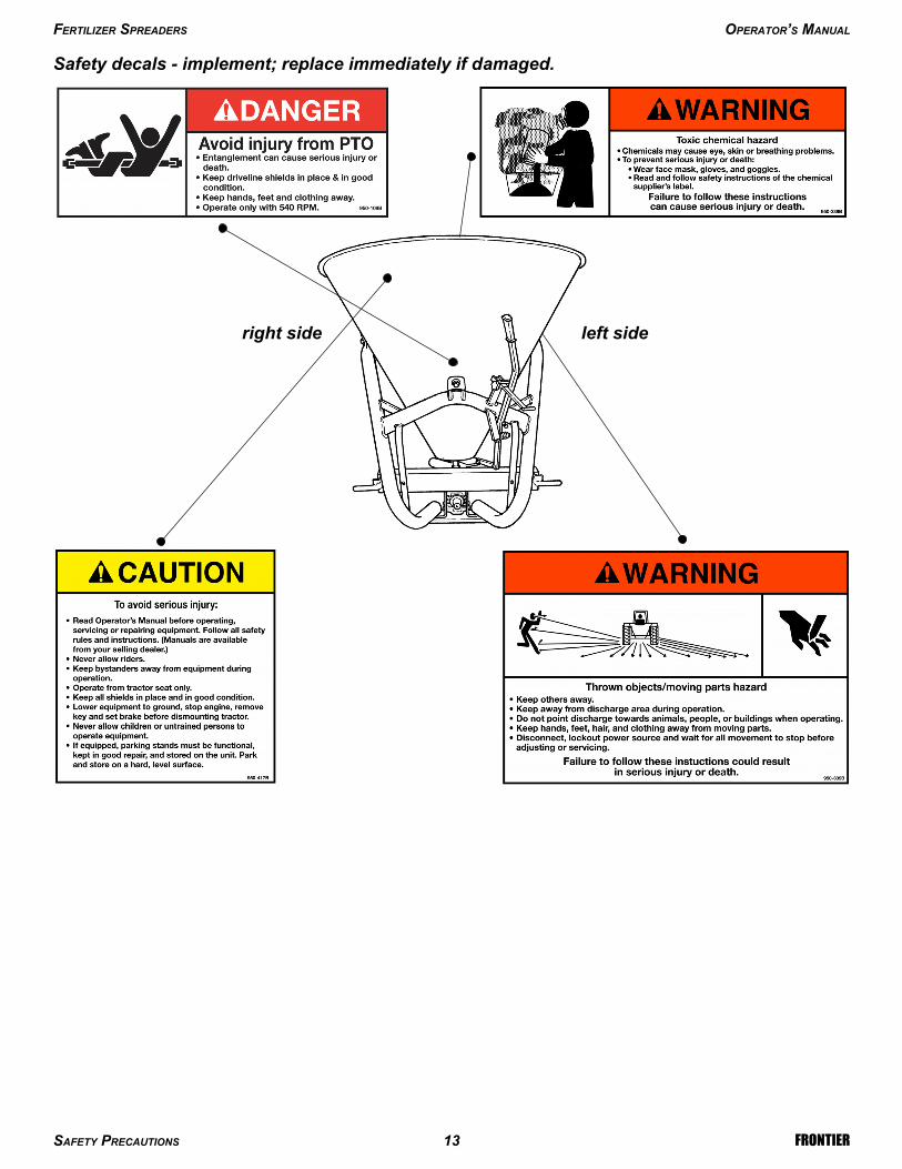
Safety decals - implement; replace immediately if damaged.
FERTILIZER SPREADERS OPERATOR’S MANUAL
SAFETY PRECAUTIONS 13 FRONTIER
right side left side

3 - OPERATION
The fertilizer spreader is versatile and ideal for granular or powdered fertilizers, seed and sand. It mayalso be used as a salt spreader for snow or ice covered roads during winter months. Our spreadersare designed for tractors from 16 to 30 PTO HP with a category 1 three point hitch.Spreaders can be used for broadcast spreading or may be used to spread prevalently to the left or tothe right with a simple adjustment.The wide range of hopper capacities and numerous spread adjustments make our fertilizer spreadersideal for use on farms, athletic fields, municipalities and many other commercial or residentialapplications.
3.01 - Operational Safety
CAUTION: Our spreaders are designed considering safety as the most important target andare the safest available in today’s market. Unfortunately, human carelessness can override thesafety features built into our machines. Injury prevention and work safety, aside from thefeatures on our spreaders, are very much due to the responsible use of the equipment. It mustalways be operated prudently following with great care, the safety instructions laid out in thismanual.
1. The use of this equipment is subject to certain hazards which cannot be prevented by mechanicalmeans or product design. All operators of this equipment must read and understand this entiremanual, paying particular attention to safety and operating instructions, prior to using.
2. Do not operate the tractor and spreader when you are tired, sick or when using medication.3. This spreader is designed for use only on tractors with 540 rpm power take off.4. Only properly trained people should operate this machine.5. Accidents are most likely to occur with machines that are loaned or rented to someone who has
not read the operator’s manual and is not familiar with a spreader.6. Always stop the tractor, set brake, shut off the tractor engine, remove the ignition key, and allow
spreader moving parts to come to a complete stop before dismounting tractor. Never leaveequipment unattended with the tractor running.
7. Never place hands or feet into hopper with tractor engine running or before you are sure all motionhas stopped. Stay clear of all moving parts.
8. Never allow any person inside the hopper for any reason. Serious injury or death can result fromsomeone becoming entangled in the agitator.
9. Do not allow riders on the spreader or tractor at any time. There is no safe place for riders.10.Never allow anyone within 50 yards of the spreader while the PTO is engaged. Product thrown
from the spreader can cause serious injury or death.11.Before backing up, look behind carefully.12. Install and secure all guards and shields before starting or operating.13.Keep hands, feet, hair and clothing away from moving parts.14.Never operate tractor and spreader under trees with low hanging limbs. Operators can be
knocked off the tractor and then run over.15.Stop spreader immediately upon striking an obstruction. Turn engine off, remove key, inspect and
repair any damage before resuming operation.
FERTILIZER SPREADERS OPERATOR’S MANUAL
OPERATION 14 FRONTIER

16.Stay alert for holes, rocks and roots in the terrain and other hidden hazards. Keep away fromdrop-offs.
17.Use extreme care and maintain minimum ground speed when transporting on hillside, over roughground and when operating close to ditches or fences. Be careful when turning sharp corners.
18.Reduce speed on slopes and sharp turns to minimize tipping or loss of control. Be careful whenchanging directions on slopes. Do not start or stop suddenly on slopes. Avoid operation on steepslopes.
19. Inspect the entire machine periodically4. Look for loose fasteners, worn or broken parts, and leakyor loose fittings.
20.Pass diagonally through sharp dips and avoid sharp drops to prevent “hanging up” tractor andspreader.
21.Avoid sudden starts and stops while traveling up or downhill.22.Always operate down slopes; never across the face. Avoid operation on steep slopes. Slow down
on sharp turns and slopes to prevent tipping and/or loss of control.23.All remote control devices (cables, ropes, rods, flexible lines, etc.) should be positioned in a way
to prevent maneuvers which could lead to accidents or damages.24.Chemicals may cause eye, skin or breathing problems. Always wear a face mask, gloves and
goggles when filling hopper.25.Before loading the fertilizer in the hopper read carefully the instructions printed on the fertilizer
canvas bag concerning the precautions to be taken in case of toxicity or corrosivity of the product.Before loading switch off the engine and remove the ignition key.
26.Load hopper with product only after the spreader has been properly attached to the tractor.
3.02 - Set Up
Notice to dealer: Pre-Delivery set up and service including lubrication are the responsibility of theauthorized dealer. It is up to him to assure that the machine is in perfect condition and ready to beused. It is his responsibility to ensure that the customer is aware of all safety aspects and operationalprocedures for the spreader. He must also fill out the Pre-Delivery Checklist5 prior to delivering thespreader.
CAUTION: Stand clear of bands when cutting as they could be under sufficient tension tocause them to fly loose. Take care in removing bands and wire, as they often have extremelysharp edges and cut very easy.
3.03 - Pre-Operational Check
Check each of the following, carefully, prior to engaging the equipment:1. No wrappings or foreign objects are around the spreader.2. All hardware is tight.3. All safety shields and guards are in place and tightly attached.4. No people or animals are in the work area.
DANGER: Shut off the tractor and remove the key before making adjustments, servicing orcleaning the machine.
FERTILIZER SPREADERS OPERATOR’S MANUAL
OPERATION 15 FRONTIER
5 See Chapter 7 - Pre-Delivery Checklist.
4 See Chapter 4 - Maintenance.

3.04 - Attaching to the Tractor
Unit may be used on tractors ranging from 16 to 30 HP equipped with a standard rear PTO andcategory 1 three point hitch6. Never use this spreader with tractors over 30 HP.
DANGER: Do not allow anyone to stand between spreader and tractor while attachingimplement.
WARNING: Never attempt to attach the implement to the tractor or make an adjustment to itwithout first turning the tractor off.
CAUTION: Check the tractor PTO rpm to ensure it is set at 540 rpm and turns clockwise.
CAUTION: Be sure the tractor tire pressure is correct. It is important to strictly follow thesafety guidelines and instructions laid out in the tractor manual.
To attach the implement to the tractor do the following:Back the tractor up to the implement in order to slip the tractor hitch arms over the hitch pins bolted tothe frame. Turn off the tractor engine and engage the park brake. Secure the two tractor hitcharms to the implement with lynch pins. Tighten the tractor arms side movement with either the swaychains or blocks to limit side swing.Connect the top link, locking it in place with the top hitch pin. Adjust it so the implement is as nearparallel to the ground as possible with the spreading disc at a distance 28” to 32” above ground level(see fig. 7).Install the end of the driveline to the spreader and the opposite end to the tractor PTO. Be sure eachend is connected securely with either the locking pin or bolt and nut. Connect the driveline shieldingchains to the tractor and to the implement to prevent the protective shielding from rotating during
FERTILIZER SPREADERS OPERATOR’S MANUAL
OPERATION 16 FRONTIER
6 See Table 2, page 24.
Fig. 7 - Hopper spreading adjustment.
28" to 32"Ground level

operation. If it was necessary to remove the PTO shielding to do any of the above operations, do notforget to replace it.
3.05 - Start Up
CAUTION: Load hopper with product only after the spreader has been properly attached to thetractor.
WARNING: Chemicals may cause eye, skin or breathing problems. Always wear a face mask,gloves and goggles when filling hopper. Refer to chemical manufacturer’s label for specificsafety information.
Before starting to use, never forget that the operator is responsible for the following:1. Safe and correct driving of the tractor and spreader.2. To learn precise, safe operating procedures for both the tractor and the spreader.3. To ensure all maintenance and lubrication has been performed on the spreader.4. To have read and understood all safety aspects for the spreader in the operator’s manual.5. To have read and understood all safety decals on the spreader.6. Checking the tractor tires for the proper pressure in accordance with the tractor operator’s manual.7. Checking that all safety shields are on the machine and securely in place.8. Making sure the proper attire is worn. Avoiding loose fitting clothing which can become entangled.
Wearing sturdy, tough-soled work shoes and protective equipment for eyes, hands, ears andhead. Never operate tractor or implements in bare feet, sandals or sneakers.
9. Ensuring proper lighting is available, sunlight or good artificial lighting.
WARNING: Use a tractor with a cab and appropriate filters on the ventilation system or wear abreathing mask capable of filtering toxic powders to prevent inhalation of product.
Prior to start working do the following:1. Make sure there are no obstructions.2. Run machine under a no-load condition for a short while to assure that everything is functioning
properly.3. Adjust all settings for the desired quantity distribution and spread pattern.4. Shift the transmission to a slow speed gear and start forward, increase the ground speed by
shifting upward until the desired speed is obtained. Do not use in reverse unless absolutelynecessary and only after careful observation of the area behind the spreader.
5. Ballast may need to be added to tractor to maintain steering control.
3.06 - Operating Techniques
WARNING: Before adjusting the spreader or filling the hopper, be sure the tractor PTO is notengaged, the tractor is shut off, and the key is removed from the tractor ignition.
FERTILIZER SPREADERS OPERATOR’S MANUAL
OPERATION 17 FRONTIER

WARNING: Before engaging the PTO, be sure no persons or animals are behind or beside thespreader.
DANGER: Never allow anyone within 50 yards of the spreader while the PTO is engaged.Product thrown from the spreader can cause serious injury or death.
DANGER: Never allow any person inside the hopper for any reason. Serious injury or deathcan result from someone becoming entangled in the agitator.
The quantity of material distributed per acre depends on the following factors:1. Spreader ground speed.2. Unit weight and size of the material to be spread.3. Spreading width.4. Position of the lever connected to the hopper gates.
The working speed depends on ground conditions. Only a test run will enable you to gauge theoptimal working speed for your conditions.
Spread adjustment for Model SS1023B:The spreading is adjustable in three ways by:1. Regulating the spread pattern.2. Regulating the amount of material to be spread.3. Regulating the spreading width.
To regulate the spread pattern slide (to the left or right) the shutter lever (see #5, fig. 2) which islocated under the hopper and runs through the slot in the mobile shutter (see #10, fig. 2). To shift theshutter lever right or left, loosen the knob over the slotted shield. This moves the spread pattern from180° at position 0 (in the center), to either mostly 90° right with the shutter lever shifted all the way tothe left or mostly 90° left when shifted to the right completely (see fig. 8).
To regulate the amount of material to be spread, using the same shutter lever as above (see #5,fig. 2), slide it in and out to regulate the size of opening at the bottom of the hopper. Use the scalelocated on the shutter lever to gauge the size opening needed. Example: if it is determined that theappropriate opening desired is position #6, loosen the knob so the blocking plate will slide. Push thelever in until the hole is completely closed and move the blocking plate to position #6 and tighten theknob. To spread, pull the lever back until it stops in position #6.
To regulate the spreading width, you should use the optional rear deflector. Move the deflector upand down to change the spreading distance. The higher the deflector is up the further the spreadwidth, the lower the less distance the material travels.To help the operator set the spreader correctly, Table 37 gives the amount of material distributed(lbs/acre) at a spreading widths (20 ft.) for each of the ten lever positions. Example: With the shutterlever in position 6, a ground speed of 2.5 mph, spreading at 20 ft., the output should be approximately553 lbs. per acre.
FERTILIZER SPREADERS OPERATOR’S MANUAL
OPERATION 18 FRONTIER
7 See Table 3 - Model SS1023B swath spread patterns, page 25.
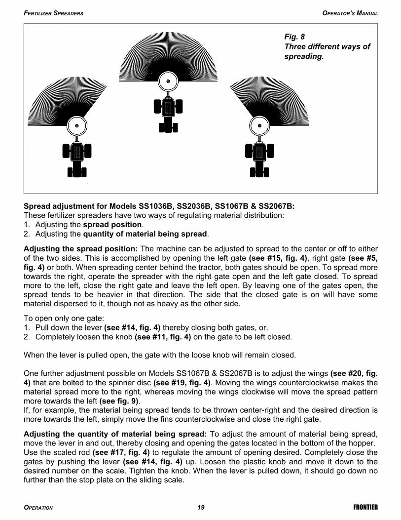
Spread adjustment for Models SS1036B, SS2036B, SS1067B & SS2067B:These fertilizer spreaders have two ways of regulating material distribution:1. Adjusting the spread position.2. Adjusting the quantity of material being spread.
Adjusting the spread position: The machine can be adjusted to spread to the center or off to eitherof the two sides. This is accomplished by opening the left gate (see #15, fig. 4), right gate (see #5,fig. 4) or both. When spreading center behind the tractor, both gates should be open. To spread moretowards the right, operate the spreader with the right gate open and the left gate closed. To spreadmore to the left, close the right gate and leave the left open. By leaving one of the gates open, thespread tends to be heavier in that direction. The side that the closed gate is on will have somematerial dispersed to it, though not as heavy as the other side.
To open only one gate:1. Pull down the lever (see #14, fig. 4) thereby closing both gates, or.2. Completely loosen the knob (see #11, fig. 4) on the gate to be left closed.
When the lever is pulled open, the gate with the loose knob will remain closed.
One further adjustment possible on Models SS1067B & SS2067B is to adjust the wings (see #20, fig.4) that are bolted to the spinner disc (see #19, fig. 4). Moving the wings counterclockwise makes thematerial spread more to the right, whereas moving the wings clockwise will move the spread patternmore towards the left (see fig. 9).If, for example, the material being spread tends to be thrown center-right and the desired direction ismore towards the left, simply move the fins counterclockwise and close the right gate.
Adjusting the quantity of material being spread: To adjust the amount of material being spread,move the lever in and out, thereby closing and opening the gates located in the bottom of the hopper.Use the scaled rod (see #17, fig. 4) to regulate the amount of opening desired. Completely close thegates by pushing the lever (see #14, fig. 4) up. Loosen the plastic knob and move it down to thedesired number on the scale. Tighten the knob. When the lever is pulled down, it should go down nofurther than the stop plate on the sliding scale.
FERTILIZER SPREADERS OPERATOR’S MANUAL
OPERATION 19 FRONTIER
Fig. 8Three different ways ofspreading.
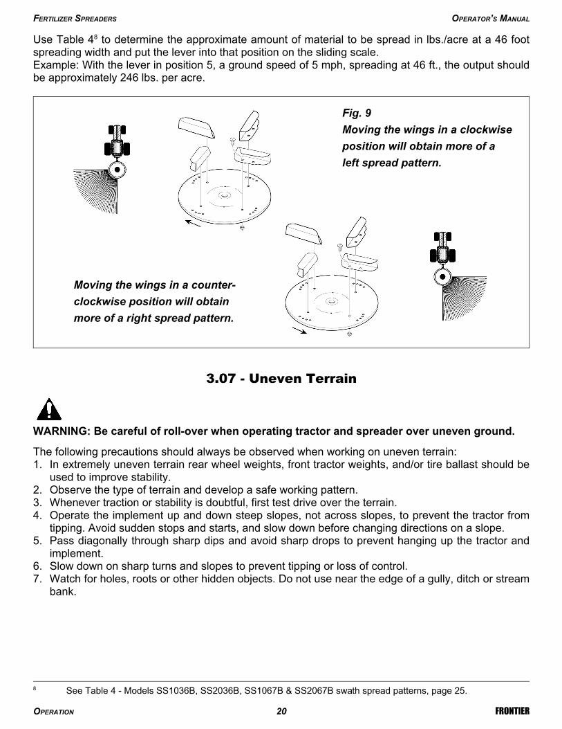
Use Table 48 to determine the approximate amount of material to be spread in lbs./acre at a 46 footspreading width and put the lever into that position on the sliding scale.Example: With the lever in position 5, a ground speed of 5 mph, spreading at 46 ft., the output shouldbe approximately 246 lbs. per acre.
3.07 - Uneven Terrain
WARNING: Be careful of roll-over when operating tractor and spreader over uneven ground.
The following precautions should always be observed when working on uneven terrain:1. In extremely uneven terrain rear wheel weights, front tractor weights, and/or tire ballast should be
used to improve stability.2. Observe the type of terrain and develop a safe working pattern.3. Whenever traction or stability is doubtful, first test drive over the terrain.4. Operate the implement up and down steep slopes, not across slopes, to prevent the tractor from
tipping. Avoid sudden stops and starts, and slow down before changing directions on a slope.5. Pass diagonally through sharp dips and avoid sharp drops to prevent hanging up the tractor and
implement.6. Slow down on sharp turns and slopes to prevent tipping or loss of control.7. Watch for holes, roots or other hidden objects. Do not use near the edge of a gully, ditch or stream
bank.
FERTILIZER SPREADERS OPERATOR’S MANUAL
OPERATION 20 FRONTIER
8 See Table 4 - Models SS1036B, SS2036B, SS1067B & SS2067B swath spread patterns, page 25.
Fig. 9
Moving the wings in a clockwise
position will obtain more of a
left spread pattern.
Moving the wings in a counter-
clockwise position will obtain
more of a right spread pattern.

4 - MAINTENANCE
DANGER: Stop engine, lock parking brake and remove key before performing any service ormaintenance.Always use personal protection devices, such as a breathing mask capable of filtering toxicpowders, safety glasses and gloves, when performing maintenance. Refer to chemicalmanufacturer’s label for specific safety information.Keep fingers out of slots to prevent injury.
4.01 - Maintenance Safety
1. Good maintenance is your responsibility.2. Keep service area clean and dry. Be sure electrical outlets and tools are properly grounded. Use
adequate light for the job at hand.3. Make sure there is plenty of ventilation. Never operate the engine of the towing vehicle in a closed
building. The exhaust fumes may cause asphyxiation.4. Make no repair or adjustments with the tractor engine running. Before working on the machine,
disengage the PTO, shut off the engine, set the brakes, and remove the ignition key.5. Be certain all moving parts on attachment have come to a complete stop before attempting to
perform maintenance.6. Never work under equipment unless it is blocked securely.7. Always use personal protection devices such as eye, hand and hearing protectors, when
performing any service or maintenance.8. Never trust the tractor hydraulics alone to support the machine. Before repairing or adjusting the
machine, it should be lowered and allowed to rest on a stand.9. Periodically tighten all bolts, nuts and screws and check that all cotter pins are properly installed to
ensure unit is in a safe condition.10.When completing a maintenance or service function, make sure all safety shields and devices are
installed before placing unit in service.11.Do not attempt to mount a tire unless you have the proper equipment and experience to do the
job.12. Inflating or servicing tires can be dangerous. Whenever possible, trained personnel should be
called to service and/or mount tires.13.After servicing, be sure all tools, parts and service equipment are removed.14.Never replace hex bolts with less than grade five bolts unless otherwise specified, i.e., shear
bolts9.15.Where replacement parts are necessary for periodic maintenance and servicing, genuine
replacement parts must be used to restore your equipment to original specifications. TheCompany will not claim responsibility for use of unapproved parts and/or accessories and otherdamages as a result of their use.
FERTILIZER SPREADERS OPERATOR’S MANUAL
MAINTENANCE 21 FRONTIER
9 Refer to Table 1 - Torque Specifications, for head identification marking, page 24.
16.Unauthorized modifications to the machine may impair the function and/or safety of the machineand reduce its life. If equipment has been altered in any way from original design, themanufacturer does not accept any liability for injury or warranty.
4.02 - Service
Before beginning work:1. Apply a thick layer of grease to all exposed moving parts.2. Apply a film of biodegradable oil in crevices and corners in order to keep corrosive material from
rusting areas that are difficult to clean.
After each use:1. Be sure to thoroughly wash the machine without using excessive pressure especially on the
moving parts. It is particularly important to wash the implement after using salt or fertilizer. Thiswill help prevent the caustic chemicals in the salt and fertilizer from destroying the metal of themachine.
2. Carefully dry the machine.3. Apply a thick layer of grease to all exposed moving parts.4. Apply a film of biodegradable oil in crevices and corners.
After seasonal use it is important to perform the following for prolonged storage:1. Wash and dry the spreader carefully.2. Inspect the spreader and replace worn or damaged parts. If corrosive material has eaten under
the paint, clean off the area with a wire brush and touch up with primer and paint.3. Tighten all hardware.4. Apply a thick layer of grease to all exposed moving parts.5. Apply a film of biodegradable oil in crevices and corners.6. Cover the spreader from the elements in order to have it in perfect condition for the start of the
next season.
NOTE: The gearbox has been filled with EP grade grease from the factory. The grease neverneeds replacing unless internal work is done to the gearbox. If necessary add SAE 90 oilthrough the suitable cap by giving the proper inclination to the fertilizer spreader.
4.03 - Driveline
DANGER: Only use the original driveline supplied with this implement and always with thesafety shielding. Carefully read and file away the driveline operator’s manual supplied by themanufacturer. The following does not substitute the information found in the driveline manual.
IMPORTANT: Always check driveline length during initial setup and when connecting to a differenttractor.
In the collapsed position the driveline should be approximately 2” from bottoming out to preventpossible damage to the tractor or implement. When the driveline is in the maximum extendedposition, the ideal minimum overlap of the two halves should be approximately 6” (see fig. 10).
FERTILIZER SPREADERS OPERATOR’S MANUAL
MAINTENANCE 22 FRONTIER

If determined that the driveline is too long, follow these procedures to adjust the length:1. Separate the two driveline halves. Connect one half to the tractor PTO and the other half to the
implement.2. Raise and lower the implement with the 3 point hitch to find the position where the driveline is
shortest. Hold the half shafts side by side and mark the desired length on the outer female tubeguard leaving a 1 ½” gap between the end of the guard tube and bell guard.
3. Cut off both guard tubes the same amount as marked in step 2.4. Shorten both drive tubes the same amount as guard tubes.5. De-burr and clean filings from drive tubes and apply grease to outside of inner telescoping tube.6. Reassemble the driveline halves and connect to tractor and implement. Raise and lower
implement again to be sure driveline does not bottom out in its shortest position and has aminimum overlap of 6” in the longest position.
7. Install both driveline safety chains. One should be hooked in a hole on the outer driveline yokeshield and to the tractor to restrict outer shield rotation. The second one should be hooked in ahole on the inner driveline yoke shield and to the implement to restrict inner shield rotation.
If determined that the driveline is too short for your tractor, contact your local dealer.
CAUTION: Always work with the driveline as straight as possible. This will prolong its life andthat of its components. It is advised not to work at an angle greater than 15 degrees.
4.04 - Transport
CAUTION: Do not tow tractor and spreader behind other vehicles. Use a properly equippedtrailer with heavy tie-downs for towing operations.
Before transporting:1. Always select a safe ground speed that is appropriate for the terrain.2. Beware of traffic on public roads. Install a SMV (Slow Moving Vehicle) sign when traveling on
roads or streets. Comply with all federal, state and local laws.3. Reduce ground speed when turning and take care that the spreader does not strike obstacles
such as trees, fences or buildings.4. Always disengage PTO before raising spreader to transport position.
FERTILIZER SPREADERS OPERATOR’S MANUAL
MAINTENANCE 23 FRONTIER
Fig. 10
MAX.
MIN.
min. 6"
min. 2"
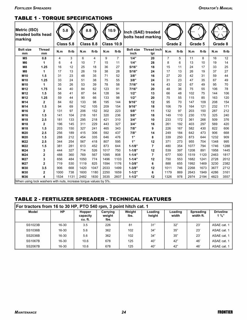
TABLE 1 - TORQUE SPECIFICATIONS
When using lock washers with nuts, increase torque values by 5%.
35574823219429749781326121-1/2”2607353518302482113115344M363161428619492643869117961-1/2”165922501180160073810002M3027123677167322687461011121-3/8”14992033104714206689063.5M30238232301469199265588861-3/8”1176159482511195307192M272012272812411682553750121-1/4”1103149677410504846563M27181724631120151950067771-1/4”80810955677693604882M24144519588911208397539121-1/8”75010175267143274443M2412881746794107735448071-1/8”6448734526132813811.5M229951348704955273371121”5958074185672543442.5M22909123264487325033981”4766463354542122881.5M20668906473642184249147/8”4375923064151892562.5M2060682243058216722697/8”3434652413271502031.5M18420569297403192261163/4”3274432293111451962M18376509266361172233103/4”3104212182951331812.5M18240325170230110149185/8”2363201612181041411.5M1621228715020397132115/8”223302152206971312M1617123212116479106189/16” 15420910514269941.5M141542081091477095129/16” 1441959813362842M14120163851155575201/2”98133669044591.25M12106144751024866131/2”94128648741561.5M127810655753648207/16”91123628440541.75M12709549673243147/16”5878395326351M10496735472331243/8”5575385124331.25M10445931422027163/8”5271354823311.5M10273719261317245/16”2838192613171M8253317241115185/16”2736182512161.25M81419101368281/4”1115710461M6121681157201/4”7946340.8M5
ft-lbN.mft-lbN.mft-lbN.mThread inch
tpiBolt size
inchft-lbN.mft-lbN.mft-lbN.m
Threadmm
Bolt sizemm
Grade 8Grade 5Grade 2
Inch (SAE) treadedbolts head marking
Class 10.9Class 8.8Class 5.8
Metric (ISO)treaded bolts headmarking
TABLE 2 - FERTILIZER SPREADER - TECHNICAL FEATURES
ASAE cat. 146’42”40”12567810.616-30SS2067B
ASAE cat. 146’42”40”12567810.616-30SS1067B
ASAE cat. 123’35”34”1023625.616-30SS2036B
ASAE cat. 123’35”34”1023625.616-30SS1036B
ASAE cat. 123’32”31”812263.516-30SS1023B
Driveline1 3/8”
Spreadingwidth ft.
Loadingwidth
Loadingheight
Weightlbs.
Carryingweight
lbs.
Hoppercapacity
cu. ft.
HPModel
For tractors from 16 to 30 HP, PTO 540 rpm, 3 point hitch cat. 1
FERTILIZER SPREADERS OPERATOR’S MANUAL
MAINTENANCE 24 FRONTIER
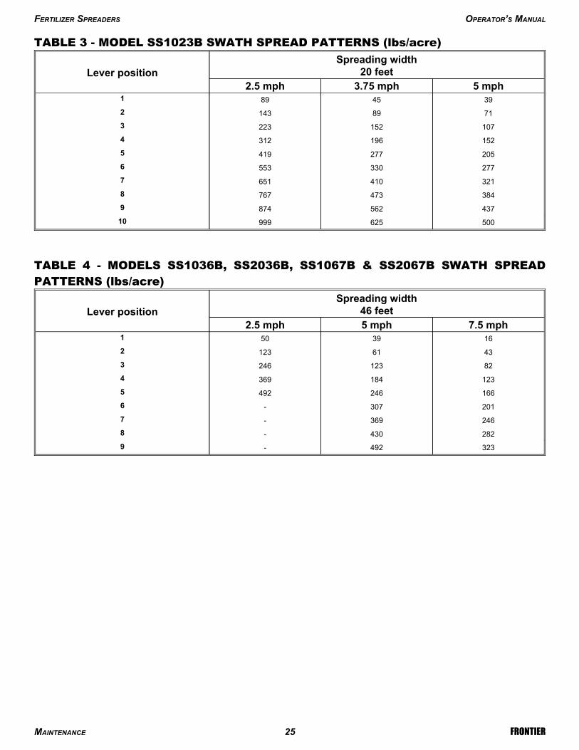
TABLE 3 - MODEL SS1023B SWATH SPREAD PATTERNS (lbs/acre)
50062599910
4375628749
3844737678
3214106517
2773305536
2052774195
1521963124
1071522233
71891432
3945891
5 mph3.75 mph2.5 mph
Spreading width20 feetLever position
TABLE 4 - MODELS SS1036B, SS2036B, SS1067B & SS2067B SWATH SPREADPATTERNS (lbs/acre)
323492-9
282430-8
246369-7
201307-6
1662464925
1231843694
821232463
43611232
1639501
7.5 mph5 mph2.5 mph
Spreading width46 feetLever position
FERTILIZER SPREADERS OPERATOR’S MANUAL
MAINTENANCE 25 FRONTIER
5 - REPAIR PROCEDURES
CAUTION: All repair procedures must be done by authorized dealerships. It is notrecommended that untrained individuals perform any repair work.
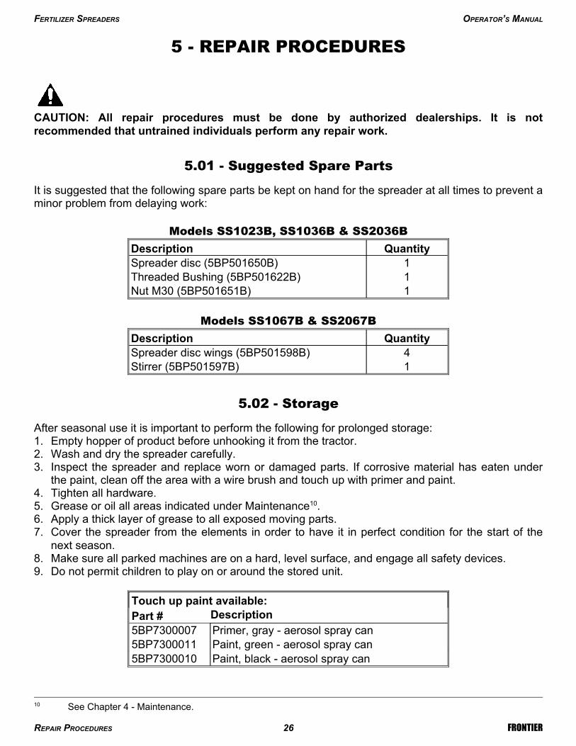
5.01 - Suggested Spare Parts
It is suggested that the following spare parts be kept on hand for the spreader at all times to prevent aminor problem from delaying work:
Models SS1023B, SS1036B & SS2036B
1Nut M30 (5BP501651B)1Threaded Bushing (5BP501622B)1Spreader disc (5BP501650B)
QuantityDescription
Models SS1067B & SS2067B
1Stirrer (5BP501597B)4Spreader disc wings (5BP501598B)
QuantityDescription
5.02 - Storage
After seasonal use it is important to perform the following for prolonged storage:1. Empty hopper of product before unhooking it from the tractor.2. Wash and dry the spreader carefully.3. Inspect the spreader and replace worn or damaged parts. If corrosive material has eaten under
the paint, clean off the area with a wire brush and touch up with primer and paint.4. Tighten all hardware.5. Grease or oil all areas indicated under Maintenance10.6. Apply a thick layer of grease to all exposed moving parts.7. Cover the spreader from the elements in order to have it in perfect condition for the start of the
next season.8. Make sure all parked machines are on a hard, level surface, and engage all safety devices.9. Do not permit children to play on or around the stored unit.
Paint, black - aerosol spray can5BP7300010Paint, green - aerosol spray can5BP7300011Primer, gray - aerosol spray can5BP7300007DescriptionPart #
Touch up paint available:
FERTILIZER SPREADERS OPERATOR’S MANUAL
REPAIR PROCEDURES 26 FRONTIER
10 See Chapter 4 - Maintenance.

6 - TROUBLESHOOTING
WARNING: Be sure tractor engine is off, parking brake is locked, and key is removed beforemaking any adjustments.
Increase PTO speed to 540 rpm.
Shorten the tractor’s top link to positionspreader so it runs level or inclined slightlyforward toward the tractor.
Incorrect PTO speed.
Hopper too far backwards.
Narrow spreadwidth.
Replace roll pin.
Replace ring or pinion gear.
Roll pin missing or sheared onthe spreader disc shaft.Broken ring or pinion gear.
PTO shaft turningbut not the gearboxoutput shaft.
Use dry product only.
Use optional tumbling agitator.
Wet product.
Powdered product.
Product not flowingto spreader disc.
Position spreader disc wings to the propersetting (see section 3.06 - OperatingTechniques).Adjust gate openings.
Spreader disc wings notpositioned properly.
Wrong gate opening.
Non uniform spreadpattern.
SOLUTIONPOSSIBLE CAUSEPROBLEM
FERTILIZER SPREADERS OPERATOR’S MANUAL
TROUBLESHOOTING 27 FRONTIER
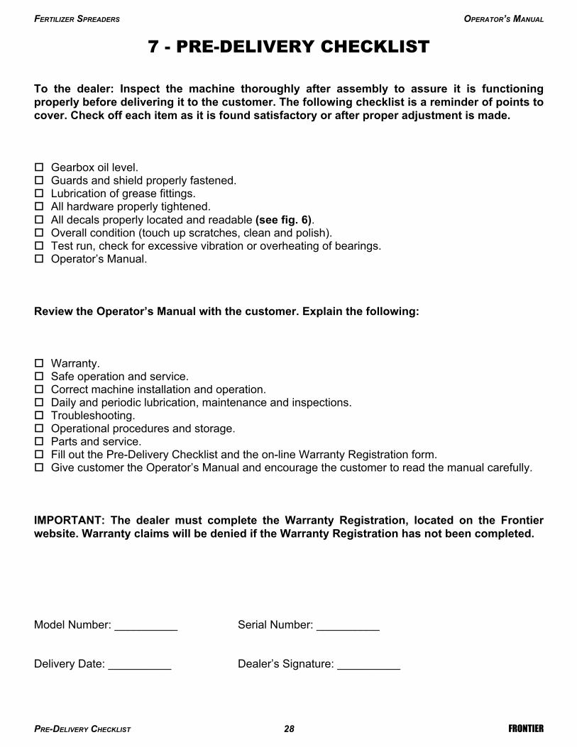
7 - PRE-DELIVERY CHECKLIST
To the dealer: Inspect the machine thoroughly after assembly to assure it is functioningproperly before delivering it to the customer. The following checklist is a reminder of points tocover. Check off each item as it is found satisfactory or after proper adjustment is made.
Gearbox oil level. Guards and shield properly fastened. Lubrication of grease fittings. All hardware properly tightened. All decals properly located and readable (see fig. 6). Overall condition (touch up scratches, clean and polish). Test run, check for excessive vibration or overheating of bearings. Operator’s Manual.
Review the Operator’s Manual with the customer. Explain the following:
Warranty. Safe operation and service. Correct machine installation and operation. Daily and periodic lubrication, maintenance and inspections. Troubleshooting. Operational procedures and storage. Parts and service. Fill out the Pre-Delivery Checklist and the on-line Warranty Registration form. Give customer the Operator’s Manual and encourage the customer to read the manual carefully.
IMPORTANT: The dealer must complete the Warranty Registration, located on the Frontierwebsite. Warranty claims will be denied if the Warranty Registration has not been completed.
Model Number: __________ Serial Number: __________
Delivery Date: __________ Dealer’s Signature: __________
FERTILIZER SPREADERS OPERATOR’S MANUAL
PRE-DELIVERY CHECKLIST 28 FRONTIER


P A R T S M A N U A L
FERTILIZER SPREADERSSS1023BSS1036BSS1067B SS2036BSS2067B
Parts Manual 05/2011203-120 Ver. D
206-121, 206-221 Ver. B209-121, 209-421, 209-422 Ver. C
Frontier Hop 203, 206, 209 (US)Printed on May 19, 2011
Note: Serial #’s with the XF prefix are subsequent to serial numbers with the BC prefix. For example: Areference to “serial # BC… 739197 & above” will also include all serial numbers with an XF prefix.

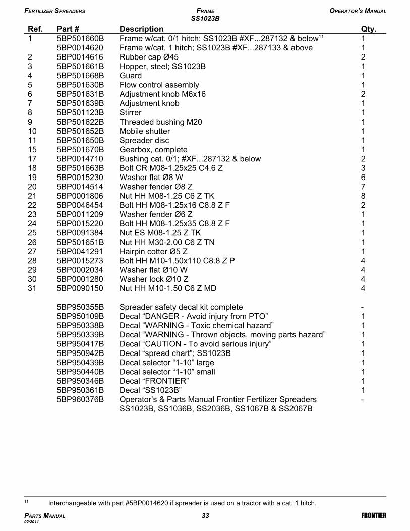
FERTILIZER SPREADERS FRAME OPERATOR’S MANUAL
SS1023B
PARTS MANUAL 32 FRONTIER02/2011
-Operator’s & Parts Manual Frontier Fertilizer SpreadersSS1023B, SS1036B, SS2036B, SS1067B & SS2067B
5BP960376B1Decal “SS1023B”5BP950361B1Decal “FRONTIER”5BP950346B1Decal selector “1-10” small5BP950440B1Decal selector “1-10” large5BP950439B1Decal “spread chart”; SS1023B5BP950942B1Decal “CAUTION - To avoid serious injury”5BP950417B1Decal “WARNING - Thrown objects, moving parts hazard”5BP950339B1Decal “WARNING - Toxic chemical hazard”5BP950338B1Decal “DANGER - Avoid injury from PTO”5BP950109B-Spreader safety decal kit complete5BP950355B
4Nut HH M10-1.50 C6 Z MD5BP0090150314Washer lock Ø10 Z5BP0001280304Washer flat Ø10 W5BP0002034294Bolt HH M10-1.50x110 C8.8 Z P5BP0015273281Hairpin cotter Ø5 Z5BP0041291271Nut HH M30-2.00 C6 Z TN5BP501651B261Nut ES M08-1.25 Z TK5BP0091384251Bolt HH M08-1.25x35 C8.8 Z F5BP0015220241Washer fender Ø6 Z5BP0011209232Bolt HH M08-1.25x16 C8.8 Z F5BP0046454228Nut HH M08-1.25 C6 Z TK5BP0001806217Washer fender Ø8 Z5BP0014514206Washer flat Ø8 W5BP0015230193Bolt CR M08-1.25x25 C4.6 Z5BP501663B182Bushing cat. 0/1; #XF...287132 & below5BP0014710171Gearbox, complete5BP501670B151Spreader disc5BP501650B111Mobile shutter5BP501652B101Threaded bushing M205BP501622B91Stirrer5BP501123B81Adjustment knob5BP501639B72Adjustment knob M6x165BP501631B61Flow control assembly5BP501630B51Guard5BP501668B41Hopper, steel; SS1023B5BP501661B32Rubber cap Ø455BP001461621Frame w/cat. 1 hitch; SS1023B #XF...287133 & above5BP00146201Frame w/cat. 0/1 hitch; SS1023B #XF...287132 & below115BP501660B1Qty.DescriptionPart #Ref.
FERTILIZER SPREADERS FRAME OPERATOR’S MANUAL
SS1023B
PARTS MANUAL 33 FRONTIER02/2011
11 Interchangeable with part #5BP0014620 if spreader is used on a tractor with a cat. 1 hitch.
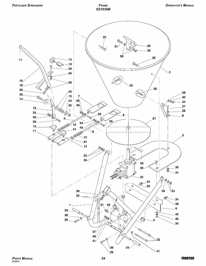
FERTILIZER SPREADERS FRAME OPERATOR’S MANUAL
SS1036B
PARTS MANUAL 34 FRONTIER05/2011

1Decal “SS1036B”5BP950432B1Decal “spread chart”; SS1036B, SS2036B, SS1067B, SS2067B5BP950369B1Hairpin cotter Ø5 Z5BP0041291454Washer lock Ø10 Z5BP0001280442Washer flat Ø14 W5BP0091435432Washer fender Ø10 Z5BP0030157426Washer flat Ø10 W5BP0002034417Washer lock Ø8 Z5BP0003144403Washer fender Ø8 Z5BP0014514399Washer flat Ø8 W5BP0015230384Nut HH M10-1.50 C6 Z MD5BP0090150371Nut ES M08-1.25 Z TK5BP0091384361Nut ES M12-1.75 Z TK5BP00133453511Nut HH M08-1.25 C6 Z MD5BP0046545346Nut HH M08-1.25 C6 Z TK5BP0001806334Bolt HH M10-1.50x110 C8.8 Z P5BP0015273321Bolt HH M08-1.25x45 C8.8 Z P5BP0014427311Bolt HH M12-1.75x80 C8.8 Z F5BP0007128304Bolt HH M08-1.25x30 C8.8 Z F5BP0046543293Bolt CR M08-1.25x20 C4.6 Z5BP0084289281Bolt HH M08-1.25x16 C8.8 Z F5BP0046454273Bolt HH M08-1.25x20 C8.8 Z F5BP0015012263Bolt CR M08-1.25x25 C4.6 Z5BP501663B252Bushing cat. 0/1; #XF...288985 & below5BP0014710241Gearbox, complete5BP0014690221Spreader disc 5BP0014647211Stationary stirrer5BP501597B201Lever stop5BP502008B191Scaled rod 5BP0014645181Rubber cap5BP0014391171Lever 5BP0014643161Spring5BP501586B151Washer flat nylon Ø125BP501585B143Adjustment knob M8x155BP501589B131Lever bracket 5BP502002B121Shutter guide plate 5BP502025B112Tension spring5BP502024B102Tie rod5BP001464191Shutter, left5BP021464081Shutter, right5BP011464071Attachment plate5BP001433861Protection5BP001463251Protection5BP001463041Hopper; SS1036B5BP021462432Rubber cap Ø455BP001461621Frame w/cat. 1 hitch; SS1036B, #XF...288986 & above5BP00146251Frame w/cat. 0/1 hitch; SS1036B, #XF...288985 & below125BP00146011Qty.DescriptionPart #Ref.
FERTILIZER SPREADERS FRAME OPERATOR’S MANUAL
SS1036B
PARTS MANUAL 35 FRONTIER05/2011
12 Interchangeable with part #5BP0014625 if spreader is used on a tractor with a cat. 1 hitch.

FERTILIZER SPREADERS FRAME OPERATOR’S MANUAL
SS2036B
PARTS MANUAL 36 FRONTIER05/2011

1Decal “SS2036B”5BP950433B1Decal “spread chart”; SS1036B, SS2036B, SS1067B, SS2067B5BP950369B1Hopper bottom plate, stainless steel5BP0014327471Bolt CR M08-1.25x25 C4.6 Z5BP501663B461Hairpin cotter Ø5 Z5BP0041291454Washer lock Ø10 Z5BP0001280442Washer flat Ø14 W5BP0091435432Washer fender Ø10 Z5BP0030157426Washer flat Ø10 W5BP00020344112Washer lock Ø8 Z5BP0003144408Washer fender Ø8 Z5BP0014514399Washer flat Ø8 W5BP0015230384Nut HH M10-1.50 C6 Z MD5BP0090150371Nut ES M08-1.25 Z TK5BP0091384361Nut ES M12-1.75 Z TK5BP00133453516Nut HH M08-1.25 C6 Z MD5BP0046545346Nut HH M08-1.25 C6 Z TK5BP0001806334Bolt HH M10-1.50x110 C8.8 Z P5BP0015273321Bolt HH M08-1.25x45 C8.8 Z P5BP0014427311Bolt HH M12-1.75x80 C8.8 Z F5BP0007128304Bolt HH M08-1.25x30 C8.8 Z F5BP0046543297Bolt CR M08-1.25x20 C4.6 Z5BP0084289281Bolt HH M08-1.25x16 C8.8 Z F5BP0046454273Bolt HH M08-1.25x20 C8.8 Z F5BP0015012263Bolt CR M08-1.25x35 C4.6 Z5BP0014619252Bushing cat. 0/1; #XF...288985 & below5BP0014710241Gearbox, complete5BP0014690221Spreader disc5BP0014647211Stationary stirrer5BP501597B201Lever stop5BP502008B191Scaled rod5BP0014645181Rubber cap5BP0014391171Lever5BP0014643161Spring5BP501586B151Washer flat nylon Ø125BP501585B143Adjustment knob M8x155BP501589B131Lever bracket5BP502002B121Shutter guide plate 5BP502025B112Tension spring5BP502024B102Tie rod5BP001464191Shutter stainless steel, left5BP021464881Shutter stainless steel, right5BP011464871Attachment plate5BP001463561Protection5BP001463251Protection5BP001463041Polyethylene hopper; SS2036B5BP021462932Rubber cap Ø455BP001461621Frame w/cat. 1 hitch; SS2036B, #XF...288986 & above5BP00146251Frame w/cat. 0/1 hitch; SS2036B, #XF...288985 & below135BP00146011Qty.DescriptionPart #Ref.
FERTILIZER SPREADERS FRAME OPERATOR’S MANUAL
SS2036B
PARTS MANUAL 37 FRONTIER05/2011
13 Interchangeable with part #5BP0014625 if spreader is used on a tractor with a cat. 1 hitch.
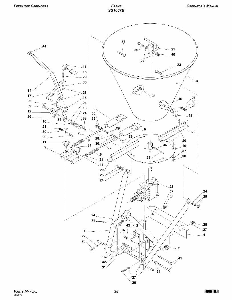
FERTILIZER SPREADERS FRAME OPERATOR’S MANUAL
SS1067B
PARTS MANUAL 38 FRONTIER06/2010

1Decal “SS1067B”5BP950348B1Decal “SMV”; SS1036B, SS2036B, SS1067B, SS2067B5BP950353B1Decal “spread chart”; SS1036B, SS2036B, SS1067B, SS2067B5BP950369B-Spreader safety decal kit complete5BP950355B1Bolt CR M08-1.25x20 C4.6 Z5BP0084289461Attachment plate, steel hopper; SS1067B5BP0014338451Rubber cap5BP0014391444Washer lock Ø10 Z5BP0001280424Bolt HH M10-1.50x110 C8.8 Z P5BP0015273411Nut ES M08-1.25 Z TK5BP0091384401Bolt HH M08-1.25x45 C8.8 Z P5BP0014427398Nut HH M06-1.00 C6 Z TK5BP501603B388Washer lock Ø6 Z5BP0046536378Bolt HH M06-1.00x16 C8.8 Z F5BP0036319361Roll pin Ø5x405BP501596B351Roll pin Ø8x405BP0029247341Nut ES M12-1.75 Z TK5BP0013345331Bolt HH M12-1.75x80 C8.8 Z F5BP0007128326Washer flat Ø10 W5BP0002034315Washer lock Ø8 Z5BP0003144304Bolt HH M08-1.25x30 C8.8 Z F5BP0046543299Nut HH M08-1.25 C6 Z MD5BP0046545287Washer flat Ø8 W5BP0015230274Bolt HH M08-1.25x20 C8.8 Z F5BP0015012266Nut HH M12-1.75 C6 Z MD5BP0001106255Washer flat Ø14 W5BP0091435243Bolt CR M12-1.75x30 C4.6 Z5BP0051073231Gearbox, complete5BP0014690221Stationary stirrer5BP501597B214Spreader wing, steel5BP501598B201Spreader disc, steel5BP501599B191Lever stop5BP502008B181Scaled rod 5BP0014396174Nut HH M10-1.50 C6 Z MD5BP0090150161Hitch lever 5BP0014384151Lever5BP0014380141Spring5BP501586B131Washer flat nylon Ø125BP501585B123Adjustment knob M8x155BP501589B111Lever bracket 5BP502002B101Shutter guide plate5BP502025B92Tension spring5BP502024B82Tie rod5BP502004B71Shutter, left5BP502003B61Shutter, right5BP502009B51Protection 5BP502013B41Hopper, steel; SS1067B5BP502014B32Rubber cap Ø605BP502020B21Frame; SS1067B, SS2067B5BP502011B1Qty.DescriptionPart #Ref.
FERTILIZER SPREADERS FRAME OPERATOR’S MANUAL
SS1067B
PARTS MANUAL 39 FRONTIER06/2010

FERTILIZER SPREADERS FRAME OPERATOR’S MANUAL
SS2067B
PARTS MANUAL 40 FRONTIER06/2010

1Decal “SS2067B”5BP950434B1Decal “SMV”; SS1036B, SS2036B, SS1067B, SS2067B5BP950353B1Decal “spread chart”; SS1036B, SS2036B, SS1067B, SS2067B5BP950369B1Rubber cap5BP0014391491Attachment plate, poly hopper5BP0014339485Washer fender Ø8 Z5BP0014514471Bolt CR M08-1.25x25 C4.6 Z5BP501663B465Bolt CR M08-1.25x20 C4.6 Z5BP0084289451Hopper bottom plate, stainless steel5BP0014327444Washer lock Ø10 Z5BP0001280424Bolt HH M10-1.50x110 C8.8 Z P5BP0015273411Nut ES M08-1.25 Z TK5BP0091384401Bolt HH M08-1.25x45 C8.8 Z P5BP0014427398Nut HH M06-1.00 C6 Z TK5BP501603B388Washer lock Ø6 Z5BP0046536378Bolt HH M06-1.00x16 C8.8 Z F5BP0036319361Roll pin Ø5x405BP501596B351Roll pin Ø8x405BP0029247341Nut ES M12-1.75 Z TK5BP0013345331Bolt HH M12-1.75x80 C8.8 Z F5BP0007128326Washer flat Ø10 W5BP00020343110Washer lock Ø8 Z5BP0003144304Bolt HH M08-1.25x30 C8.8 Z F5BP00465432914Nut HH M08-1.25 C6 Z MD5BP0046545287Washer flat Ø8 W5BP0015230274Bolt HH M08-1.25x20 C8.8 Z F5BP0015012266Nut HH M12-1.75 C6 Z MD5BP0001106255Washer flat Ø14 W5BP0091435243Bolt CR M12-1.75x40 C8.8 Z5BP0044115231Gearbox, complete5BP0014690221Stationary stirrer5BP501597B214Spreader wing, stainless steel5BP0014414201Spreader disc, stainless steel5BP0014410191Lever stop5BP502008B181Scaled rod 5BP0014396174Nut HH M10-1.50 C6 Z MD5BP0090150161Hitch lever 5BP0014384151Lever 5BP0014380141Spring 5BP501586B131Washer flat nylon Ø125BP501585B123Adjustment knob M8x155BP501589B111Lever bracket 5BP502002B101Shutter guide plate 5BP502025B92Tension spring5BP502024B82Tie rod5BP502004B71Shutter stainless steel, left5BP021434061Shutter stainless steel, right5BP011434051Protection 5BP502013B41Hopper polyethylene; SS2067B5BP011432632Rubber cap Ø605BP502020B21Frame; SS1067B, SS2067B5BP502011B1Qty.DescriptionPart #Ref.
FERTILIZER SPREADERS FRAME OPERATOR’S MANUAL
SS2067B
PARTS MANUAL 41 FRONTIER06/2010
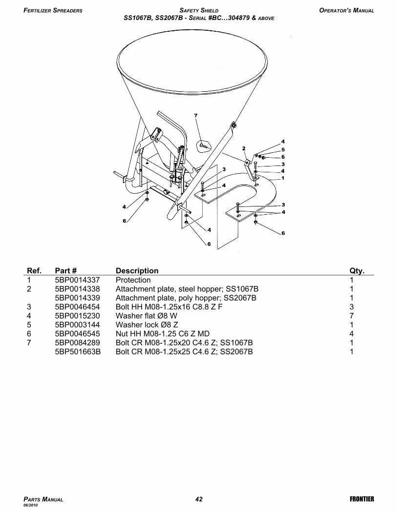
1Bolt CR M08-1.25x25 C4.6 Z; SS2067B5BP501663B1Bolt CR M08-1.25x20 C4.6 Z; SS1067B5BP008428974Nut HH M08-1.25 C6 Z MD5BP004654561Washer lock Ø8 Z5BP000314457Washer flat Ø8 W5BP001523043Bolt HH M08-1.25x16 C8.8 Z F5BP004645431Attachment plate, poly hopper; SS2067B5BP00143391Attachment plate, steel hopper; SS1067B5BP001433821Protection5BP00143371Qty.DescriptionPart #Ref.
FERTILIZER SPREADERS SAFETY SHIELD OPERATOR’S MANUAL
SS1067B, SS2067B - SERIAL #BC…304879 & ABOVE
PARTS MANUAL 42 FRONTIER06/2010
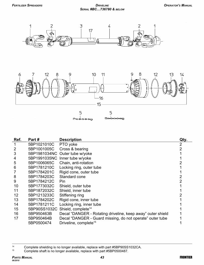
1Driveline, complete155BP05004741Decal “DANGER - Guard missing, do not operate” outer tube5BP950464B171Decal “DANGER - Rotating driveline, keep away” outer shield5BP950463B161Shield, complete145BP90SS1032C151Locking ring, inner tube5BP1781211C141Rigid cone, inner tube5BP1784202C132Stiffening ring5BP1213233C121Shield, inner tube5BP1872032C111Shield, outer tube5BP1773032C102Pin5BP1784212C92Standard cone5BP1784203C81Rigid cone, outer tube5BP1784201C71Locking ring, outer tube5BP1781210C62Chain, anti-rotation5BP1006065C51Inner tube w/yoke5BP1991035NC41Outer tube w/yoke5BP1981034NC32Cross & bearing 5BP1001005C22PTO yoke5BP1021010C1Qty.DescriptionPart #Ref.
FERTILIZER SPREADERS DRIVELINE OPERATOR’S MANUAL
SERIAL #BC…736780 & BELOW
PARTS MANUAL 43 FRONTIER06/2010
15 Complete shaft is no longer available, replace with part #5BP0500487.
14 Complete shielding is no longer available, replace with part #5BP90SS1032CA.
-Driveline, complete5BP05004871Decal “DANGER - Guard missing, do not operate” outer tube5BP950464B131Decal “DANGER - Rotating driveline, keep away” outer shield5BP950463B122Chain, anti-rotation5BP1006065C111Shield, complete5BP90SS1032CA101Locking ring, inner tube5BP1781211CA91Shield, inner tube5BP1872032CA81Shield, outer tube5BP1773032CA72Cone, outer tube5BP1784203CA61Locking ring, outer tube5BP1781210CA51Inner tube w/yoke5BP1991035NC41Outer tube w/yoke5BP1981034NC32Cross & bearing5BP1001005C22PTO yoke5BP1021010C1Qty.DescriptionPart #Ref.
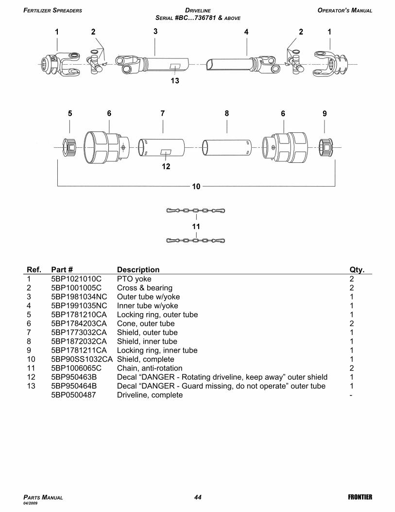
FERTILIZER SPREADERS DRIVELINE OPERATOR’S MANUAL
SERIAL #BC…736781 & ABOVE
PARTS MANUAL 44 FRONTIER04/2009
-Driveline, complete 5BP05004841Decal “DANGER - Guard missing, do not operate” outer tube5BP950464B131Decal “DANGER - Rotating driveline, keep away” outer shield5BP950463B122Chain, anti-rotation5BP1006065C111Shield, complete5BP0014448101Locking ring, inner tube5BP1781211CA91Shield, inner tube5BP001444781Shield, outer tube5BP001444672Cone, outer tube5BP1784203CA61Locking ring, outer tube5BP1781210CA51Inner tube w/yoke5BP001444541Outer tube w/yoke5BP001444432Cross & bearing 5BP1001005C22PTO yoke5BP1021010C1Qty.DescriptionPart #Ref.
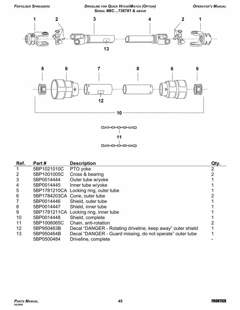
FERTILIZER SPREADERS DRIVELINE FOR QUICK HITCH/IMATCH (OPTION) OPERATOR’S MANUAL
SERIAL #BC…736781 & ABOVE
PARTS MANUAL 45 FRONTIER04/2009
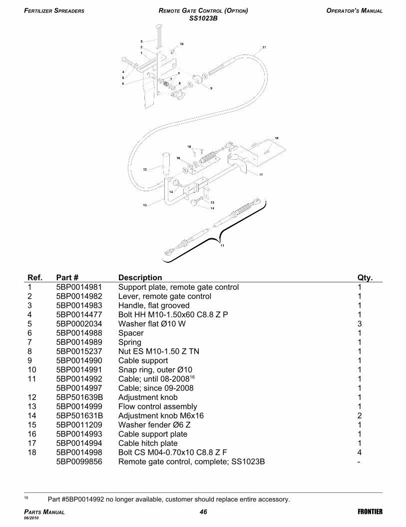
-Remote gate control, complete; SS1023B5BP00998564Bolt CS M04-0.70x10 C8.8 Z F5BP0014998181Cable hitch plate5BP0014994171Cable support plate5BP0014993161Washer fender Ø6 Z5BP0011209152Adjustment knob M6x165BP501631B141Flow control assembly5BP0014999131Adjustment knob5BP501639B121Cable; since 09-20085BP00149971Cable; until 08-2008165BP0014992111Snap ring, outer Ø105BP0014991101Cable support5BP001499091Nut ES M10-1.50 Z TN5BP001523781Spring 5BP001498971Spacer5BP001498863Washer flat Ø10 W5BP000203451Bolt HH M10-1.50x60 C8.8 Z P5BP001447741Handle, flat grooved5BP001498331Lever, remote gate control5BP001498221Support plate, remote gate control5BP00149811Qty.DescriptionPart #Ref.
FERTILIZER SPREADERS REMOTE GATE CONTROL (OPTION) OPERATOR’S MANUAL
SS1023B
PARTS MANUAL 46 FRONTIER06/2010
16 Part #5BP0014992 no longer available, customer should replace entire accessory.
-Remote gate control, complete; SS1036B, SS2036B, SS1067B,SS2067B
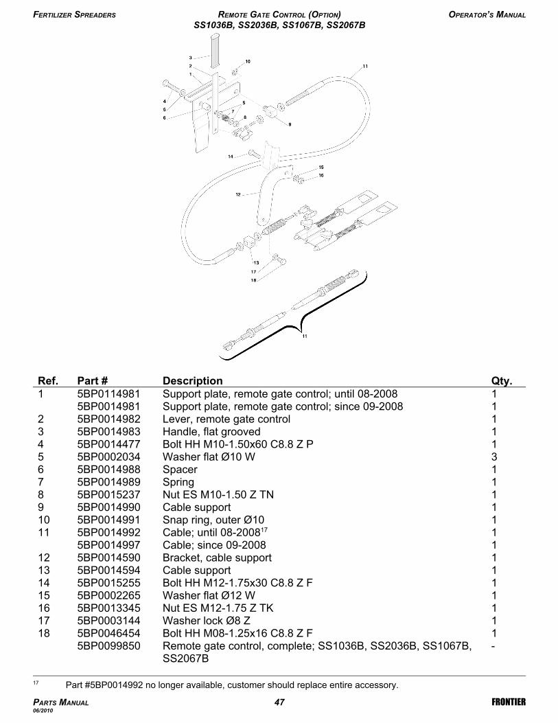
5BP00998501Bolt HH M08-1.25x16 C8.8 Z F5BP0046454181Washer lock Ø8 Z5BP0003144171Nut ES M12-1.75 Z TK5BP0013345161Washer flat Ø12 W5BP0002265151Bolt HH M12-1.75x30 C8.8 Z F5BP0015255141Cable support5BP0014594131Bracket, cable support5BP0014590121Cable; since 09-20085BP00149971Cable; until 08-2008175BP0014992111Snap ring, outer Ø105BP0014991101Cable support5BP001499091Nut ES M10-1.50 Z TN5BP001523781Spring5BP001498971Spacer5BP001498863Washer flat Ø10 W5BP000203451Bolt HH M10-1.50x60 C8.8 Z P5BP001447741Handle, flat grooved5BP001498331Lever, remote gate control5BP001498221Support plate, remote gate control; since 09-20085BP00149811Support plate, remote gate control; until 08-20085BP01149811Qty.DescriptionPart #Ref.
FERTILIZER SPREADERS REMOTE GATE CONTROL (OPTION) OPERATOR’S MANUAL
SS1036B, SS2036B, SS1067B, SS2067B
PARTS MANUAL 47 FRONTIER06/2010
17 Part #5BP0014992 no longer available, customer should replace entire accessory.
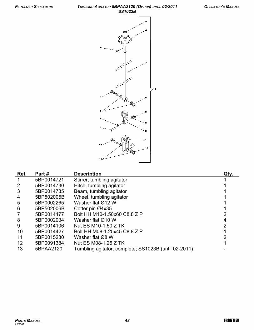
-Tumbling agitator, complete; SS1023B (until 02-2011)5BPAA2120131Nut ES M08-1.25 Z TK5BP0091384122Washer flat Ø8 W5BP0015230111Bolt HH M08-1.25x45 C8.8 Z P5BP0014427102Nut ES M10-1.50 Z TK5BP001410694Washer flat Ø10 W5BP000203482Bolt HH M10-1.50x60 C8.8 Z P5BP001447771Cotter pin Ø4x355BP502006B61Washer flat Ø12 W5BP000226551Wheel, tumbling agitator5BP502005B41Beam, tumbling agitator5BP001473531Hitch, tumbling agitator5BP001473021Stirrer, tumbling agitator5BP00147211Qty.DescriptionPart #Ref.
FERTILIZER SPREADERS TUMBLING AGITATOR 5BPAA2120 (OPTION) UNTIL 02/2011 OPERATOR’S MANUAL
SS1023B
PARTS MANUAL 48 FRONTIER01/2007

-Tumbling agitator, complete; SS1023B (since 03/2011)5BP00999791Bolt HH M08-1.25x45 C8.8 Z P5BP0014427121Nut ES M08-1.25 Z TK5BP0091384112Washer flat Ø08 W5BP0015230101Cotter pin Ø4x355BP000117491Wheel, tumbling agitator5BP001448883Washer flat Ø12 W5BP000226571Bolt HH M12-1.75x60 C8.8 ZP5BP001474662Nut PT M12-1.75 C6 TK Z5BP003006451Washer fender Ø12 Z5BP007610641Beam, tumbling agitator5BP001474431Hitch, tumbling agitator5BP001473921Stirrer, tumbling agitator5BP00147421Qty.DescriptionPart #Ref.
FERTILIZER SPREADERS TUMBLING AGITATOR 5BP0099979 (OPTION) SINCE 03/2011 OPERATOR’S MANUAL
SS1023B
PARTS MANUAL 49 FRONTIER03/2011
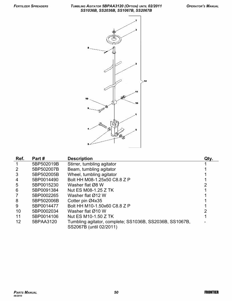
-Tumbling agitator, complete; SS1036B, SS2036B, SS1067B,SS2067B (until 02/2011)
5BPAA3120121Nut ES M10-1.50 Z TK5BP0014106112Washer flat Ø10 W5BP0002034101Bolt HH M10-1.50x60 C8.8 Z P5BP001447791Cotter pin Ø4x355BP502006B81Washer flat Ø12 W5BP000226571Nut ES M08-1.25 Z TK5BP009138462Washer flat Ø8 W5BP001523051Bolt HH M08-1.25x50 C8.8 Z P5BP001449041Wheel, tumbling agitator5BP502005B31Beam, tumbling agitator5BP502007B21Stirrer, tumbling agitator5BP502019B1Qty.DescriptionPart #Ref.
FERTILIZER SPREADERS TUMBLING AGITATOR 5BPAA3120 (OPTION) UNTIL 02/2011 OPERATOR’S MANUAL
SS1036B, SS2036B, SS1067B, SS2067B
PARTS MANUAL 50 FRONTIER06/2010
-Tumbling agitator, complete;SS1036B, SS2036B, SS1067B,SS2067B (since 03/2011)
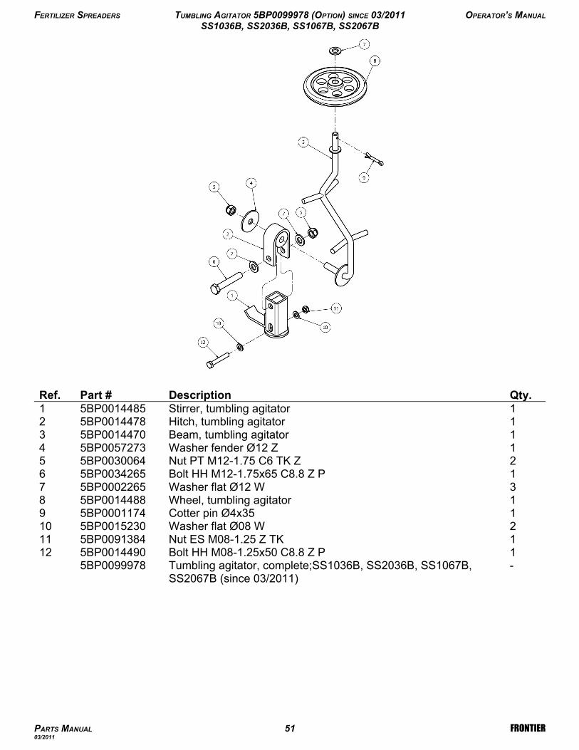
5BP00999781Bolt HH M08-1.25x50 C8.8 Z P5BP0014490121Nut ES M08-1.25 Z TK5BP0091384112Washer flat Ø08 W5BP0015230101Cotter pin Ø4x355BP000117491Wheel, tumbling agitator5BP001448883Washer flat Ø12 W5BP000226571Bolt HH M12-1.75x65 C8.8 Z P5BP003426562Nut PT M12-1.75 C6 TK Z5BP003006451Washer fender Ø12 Z5BP005727341Beam, tumbling agitator5BP001447031Hitch, tumbling agitator5BP001447821Stirrer, tumbling agitator5BP00144851Qty.DescriptionPart #Ref.
FERTILIZER SPREADERS TUMBLING AGITATOR 5BP0099978 (OPTION) SINCE 03/2011 OPERATOR’S MANUAL
SS1036B, SS2036B, SS1067B, SS2067B
PARTS MANUAL 51 FRONTIER03/2011
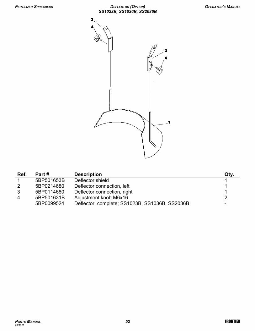
-Deflector, complete; SS1023B, SS1036B, SS2036B5BP00995242Adjustment knob M6x165BP501631B41Deflector connection, right5BP011468031Deflector connection, left5BP021468021Deflector shield5BP501653B1Qty.DescriptionPart #Ref.
FERTILIZER SPREADERS DEFLECTOR (OPTION) OPERATOR’S MANUAL
SS1023B, SS1036B, SS2036B
PARTS MANUAL 52 FRONTIER01/2010

-Deflector, complete; SS1067B, SS2067B5BP00996382Nut ES M08-1.25 Z TK5BP009138472Washer flat Ø8 W5BP001523062Washer fender Ø8 Z5BP001451452Bolt HH M08-1.25x30 C8.8 Z F5BP004654342Adjustment knob M8x155BP501589B32Deflector connection5BP001450521Deflector shield5BP00145011Qty.DescriptionPart #Ref.
FERTILIZER SPREADERS DEFLECTOR (OPTION) OPERATOR’S MANUAL
SS1067B, SS2067B
PARTS MANUAL 53 FRONTIER06/2010
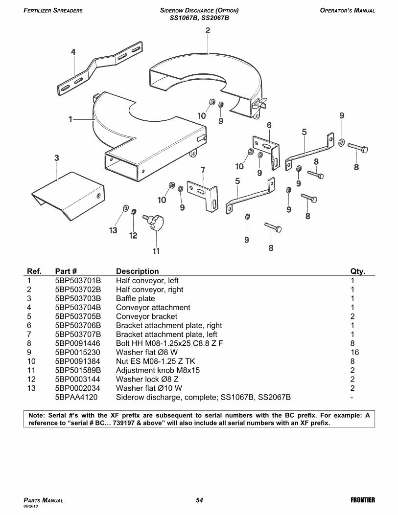
-Siderow discharge, complete; SS1067B, SS2067B5BPAA41202Washer flat Ø10 W5BP0002034132Washer lock Ø8 Z5BP0003144122Adjustment knob M8x155BP501589B118Nut ES M08-1.25 Z TK5BP00913841016Washer flat Ø8 W5BP001523098Bolt HH M08-1.25x25 C8.8 Z F5BP009144681Bracket attachment plate, left5BP503707B71Bracket attachment plate, right5BP503706B62Conveyor bracket5BP503705B51Conveyor attachment5BP503704B41Baffle plate5BP503703B31Half conveyor, right5BP503702B21Half conveyor, left5BP503701B1Qty.DescriptionPart #Ref.
FERTILIZER SPREADERS SIDEROW DISCHARGE (OPTION) OPERATOR’S MANUAL
SS1067B, SS2067B
PARTS MANUAL 54 FRONTIER06/2010
Note: Serial #’s with the XF prefix are subsequent to serial numbers with the BC prefix. For example: Areference to “serial # BC… 739197 & above” will also include all serial numbers with an XF prefix.

Use only original spare parts
All rights reserved. It is unlawful to copy, reprint or use any of the information or details in this manualwithout the expressed written permission of the Company. Technical information provided in thismanual is approximate, the Company reserves the right to modify or improve the models shown fortechnical or commercial purposes. Pictures in this manual do not necessarily show the machine asdelivered.

Manual 5BP960376BDate 05/19/2011
Fro
ntie
r H
op
20
3,
20
6,
20
9 (
US
) P
rinte
d in
th
e U
SA
, M
ay
19
, 2
01
1


