13
08/2012 TOS VARNSDORF a.s. N e w g o a ls n e e d ne w s o l ut i on s HORIZONTAL MILLING AND BORING MACHINES WHN 13/15 CNC WHQ 13/15 CNC WHN 13/15 MC WHQ 13/15 MC reg. č. 12392-01
08
/20
12
T O S VA R N S D O R F a . s .
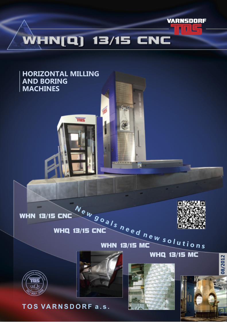
N e w g o a l s n e e d n e w s o l u t i o n s
HORIZONTAL MILLING AND BORING MACHINES
WHN 13/15 CNC
WHQ 13/15 CNC
WHN 13/15 MC
WHQ 13/15 MC
reg. č. 12392-01

2C
ON
TEN
T
3 (0.01mm) 1 my
z
x > 1 my > 1 mz > 1 m
x
1
201
2
TECHNICAL PARAMETERS
HEADSTOCK
DESIGN OF MACHINE GROUPS
MACHINE CONTROL
AUTOMATIC TOOL CHANGE (ATC)
OPTIONAL ACCESSORIES
TECHNOLOGIES
ABOUT COMPANY
CONTENT
HORIZONTAL MILLING AND BORING MACHINE WHN(Q) 13/15 CNC
TECHNOLOGIES / REFERENCES
AUTOMATIC PALLET CHANGE (APC)
MACHINE LAYOUT
22
56
910
1316
1718
1921
4
3
2
1
AB
OU
T C
OM
PA
NY
www.tosvarnsdorf.com
ABOUT COMPANY
Company TOS VARNSDORF a.s. situated in Varnsdorf, Czech Republic has a years-lasting tradition in machine tool production. The company was founded, under the name of Arno Plauert Machine Works, as early as 1903 and up to now it grew up into a big engineering company, known with its products all around the world.
The company's manufacturing program is based on the development, manufacture and sale of machine tools, integrated with a wide offer of services, such as:
- training for operators and maintenance workers - technological studies- installations of new machines- warranty and after-warranty (extended) servicing- spare parts sales- overhauls and modernizations
In addition, the company provides for the services in the form of outwork offers (Metalworking, Measuring services, Chemical and Heat Treatment of Metals).
High engineering standards of TOS VARNSDORF a. s. products were recognized in 1996 when the companywas awarded the ISO 9001 certificate.
PRODUCTION PROGRAMPRODUCTION OF MACHINE TOOLS
• HORIZONTAL MILLING AND BORING MACHINES• FLOOR TYPE HORIZONTAL BORING MILLS• MACHINING CENTRES• PORTAL TYPE MACHINING CENTRES• SPECIAL MACHINES• ACCESSORIES
SERVICES
• TECHNOLOGICAL SUPPORT: TRAINING, TECHNOLOGICAL STUDIES, ETC.• SPARE PARTS, OVERHAULS AND MODERNIZATIONS• COOPERATION (METALWORKING, MEASURING SERVICES, CHEMICAL AND HEAT TREATMENT OF METALS)
CONTENT
7
8
1112
3
4
43
HO
RIZ
ON
TA
L M
ILLIN
G A
ND
BO
RIN
G
MA
CH
INE W
HN
(Q)
13
/15
CN
C
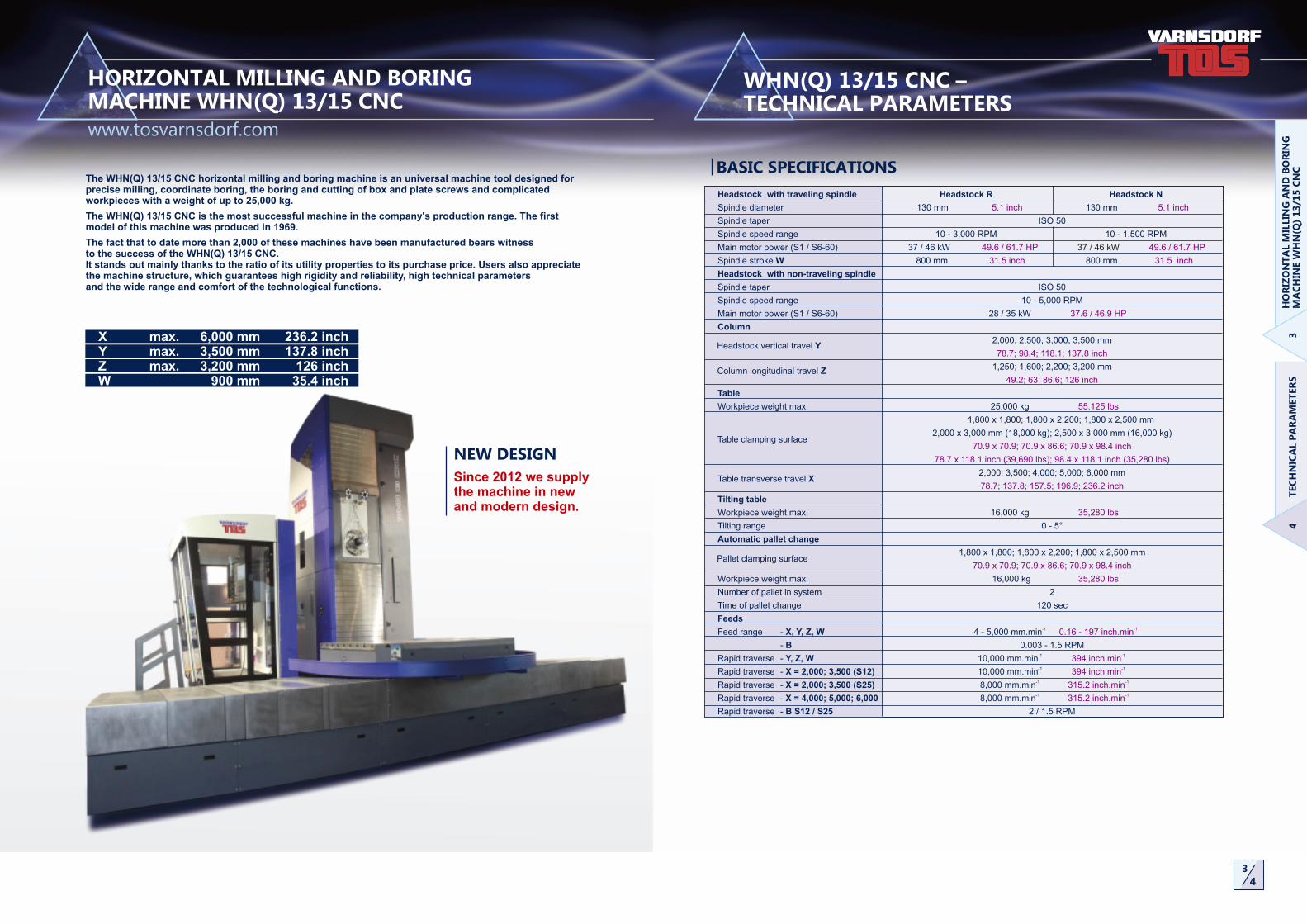
The WHN(Q) 13/15 CNC horizontal milling and boring machine is an universal machine tool designed for precise milling, coordinate boring, the boring and cutting of box and plate screws and complicated workpieces with a weight of up to 25,000 kg.
The WHN(Q) 13/15 CNC is the most successful machine in the company's production range. The first model of this machine was produced in 1969.
The fact that to date more than 2,000 of these machines have been manufactured bears witness to the success of the WHN(Q) 13/15 CNC. It stands out mainly thanks to the ratio of its utility properties to its purchase price. Users also appreciate the machine structure, which guarantees high rigidity and reliability, high technical parameters and the wide range and comfort of the technological functions.
NEW DESIGN
Since 2012 we supply the machine in new and modern design.
BASIC SPECIFICATIONS
Headstock with traveling spindle Headstock R Headstock N
Spindle diameter 130 mm 130 mm 5.1 inch 5.1 inch
Spindle taper ISO 50
Spindle speed range 10 - 3,000 RPM 10 - 1,500 RPM
Main motor power (S1 / S6-60) 37 / 46 kW 49.6 / 61.7 HP 37 / 46 kW 49.6 / 61.7 HP
Spindle stroke W 800 mm 800 mm 31.5 inch 31.5 inch
Headstock with non-traveling spindle
Spindle taper ISO 50
Spindle speed range 10 - 5,000 RPM
Main motor power (S1 / S6-60) 28 / 35 kW 37.6 / 46.9 HP
Column
2,000; 2,500; 3,000; 3,500 mm
78.7; 98.4; 118.1; 137.8 inch
1,250; 1,600; 2,200; 3,200 mm
49.2; 63; 86.6; 126 inch
Table
Workpiece weight max. 25,000 kg 55.125 lbs
1,800 x 1,800; 1,800 x 2,200; 1,800 x 2,500 mm
2,000 x 3,000 mm (18,000 kg); 2,500 x 3,000 mm (16,000 kg)
70.9 x 70.9; 70.9 x 86.6; 70.9 x 98.4 inch
78.7 x 118.1 inch (39,690 lbs); 98.4 x 118.1 inch (35,280 lbs)
2,000; 3,500; 4,000; 5,000; 6,000 mm
78.7; 137.8; 157.5; 196.9; 236.2 inch
Tilting table
Workpiece weight max. 16,000 kg 35,280 lbs
Tilting range 0 - 5°
Automatic pallet change
1,800 x 1,800; 1,800 x 2,200; 1,800 x 2,500 mm
70.9 x 70.9; 70.9 x 86.6; 70.9 x 98.4 inch
Workpiece weight max. 16,000 kg 35,280 lbs
Number of pallet in system 2
Time of pallet change 120 sec
Feeds-1Feed range - X, Y, Z, W 4 - 5,000 mm.min -10.16 - 197 inch.min
- B 0.003 - 1.5 RPM-1Rapid traverse - Y, Z, W 10,000 mm.min -1394 inch.min-1Rapid traverse - X = 2,000; 3,500 (S12) 10,000 mm.min -1394 inch.min
-1Rapid traverse - X = 2,000; 3,500 (S25) 8,000 mm.min -1315.2 inch.min-1Rapid traverse - X = 4,000; 5,000; 6,000 8,000 mm.min -1315.2 inch.min
Rapid traverse - B S12 / S25 2 / 1.5 RPM
TEC
HN
ICA
L P
AR
AM
ET
ER
S
www.tosvarnsdorf.com
WHN(Q) 13/15 CNC – TECHNICAL PARAMETERS
X max. 6,000 mm 236.2 inch Y max. 3,500 mm 137.8 inch Z max. 3,200 mm 126 inch W 900 mm 35.4 inch
HORIZONTAL MILLING AND BORING MACHINE WHN(Q) 13/15 CNC
Table clamping surface
Table transverse travel X
Pallet clamping surface
Headstock vertical travel Y
Column longitudinal travel Z

THE SPINDLE PULLOUTis accomplished using an independent servo-drive. Equipment for sensing the revolutions of the spindle and for measuring the spindle pullout using a HEIDENHAIN electrical-optical linear measuring scale is located on the headstock taile.
THE SPINDLE DRIVE has been resolved in two mechanical rows banked automatically by hydraulic feeding attachments.
5
6
HEA
DS
TO
CK
WHN(Q) 13 CNC
THE HEADSTOCKcontains all the spindle bearings and the spindle driving mechanism as well as the ones for the longitudinal travel of the live spindle (W-axis). The main housing of spindle heads consists of an assembly of hollow and work spindles. The hollow spindle (quill) is housed in precision spindle oblique-contact ball bearings in a multiple pre-stressed design. The work spindle is nitrided, hardened and mounted to slide with a minimum clearance in the hollow spindle.Clamping of tools is lever operated; the clamping force is created by plate springs; hydraulically controlled process of releasing. Also, the customer may request the tool clamping in the BIG-PLUS system. During the automatic tool change, the taper is cleaned with pressure air.
THE HEADSTOCK „15“ - SPINDLE DIAMETER 150 MM // 5.9 INCHIn case of customer's wish the machine can be deliver in design „15“ with spindle diameter of 150 mm // 5.9 inch.
5 6
P[kW] M[Nm]
-1n[R.P.M. ]
SPINDLE „R”
2,50237
14
2
3,0
00
P[kW] M[Nm]
-1n[R.P.M. ]
SPINDLE „N”
3,322
37
10
7
1,5
00
P[kW] M[Nm]
-1n[R.P.M. ]
NON TRAVELING SPINDLE
1,018
28
26
2
5,0
00
W=800
B1003094
13
0j5
40
0h
6
22
1.4
4h
5
BASIC TECHNICAL PARAMETERS
SPINDLE TYPE Headstock R Headstock N
Main motor power S1/S6-60 37 / 46 kW 37 / 46 kW 49.6 / 61.7 HP 49.6 / 61.7 HP
Max. spindle torque S1/S6-60 2,502 / 3,111 Nm 3,322 / 4,132 Nm 1,845 / 2,294 ft lb 2,450 / 3,047 ft lb
NON TRAVELING SPINDLE
Main motor power S1/S6-60 28 / 35 kW 37.6 / 46.9 HP
Spindle torque S1/S6-60 1,018 / 1,265 Nm 751 / 933 ft lb
www.tosvarnsdorf.com
WHN(Q) 13/15 CNC – HEADSTOCK
Spindle diameter 150 mm 5.9 inch
Spindle speed range 10 - 3,000 RPM
Main motor power S1 46 kW 61.7 HP
Max. spindle torque S1 3,100 Nm 2,286 ft lb
Spindle stroke W 9900 mm 35.4 inch
78
7
8
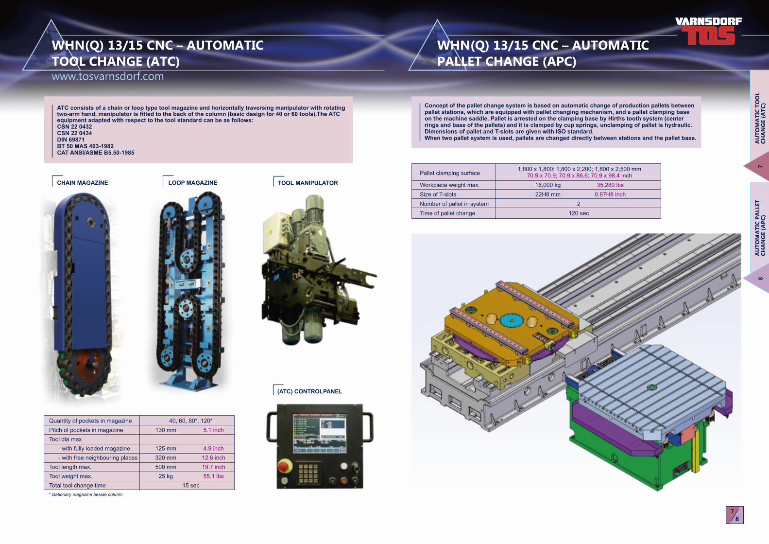
TOOL MANIPULATOR
(ATC) CONTROLPANEL
* stationary magazine beside column
Quantity of pockets in magazine 40, 60, 80*, 120*
Pitch of pockets in magazine 130 mm 5.1 inch
Tool dia max
- with fully loaded magazine 125 mm 4.9 inch
- with free neighbouring places 320 mm 12.6 inch
Tool length max. 500 mm 19.7 inch
Tool weight max. 25 kg 55.1 lbs
Total tool change time 15 sec
ATC consists of a chain or loop type tool magazine and horizontally traversing manipulator with rotating two-arm hand, manipulator is fitted to the back of the column (basic design for 40 or 60 tools).The ATC equipment adapted with respect to the tool standard can be as follows:CSN 22 0432CSN 22 0434DIN 69871BT 50 MAS 403-1982CAT ANSI/ASME B5.50-1985
WHN(Q) 13/15 CNC – AUTOMATIC TOOL CHANGE (ATC)
WHN(Q) 13/15 CNC – AUTOMATIC PALLET CHANGE (APC)
AU
TO
MA
TIC
TO
OL
CH
AN
GE (
AT
C)
AU
TO
MA
TIC
PA
LLET
C
HA
NG
E (
AP
C)
LOOP MAGAZINECHAIN MAGAZINE
www.tosvarnsdorf.com
Concept of the pallet change system is based on automatic change of production pallets between pallet stations, which are equipped with pallet changing mechanism, and a pallet clamping base on the machine saddle. Pallet is arrested on the clamping base by Hirths tooth system (center rings and base of the pallets) and it is clamped by cup springs, unclamping of pallet is hydraulic.Dimensions of pallet and T-slots are given with ISO standard.When two pallet system is used, pallets are changed directly between stations and the pallet base.
1,800 x 1,800; 1,800 x 2,200; 1,800 x 2,500 mm 70.9 x 70.9; 70.9 x 86.6; 70.9 x 98.4 inch
Workpiece weight max. 16,000 kg 35,280 lbs
Size of T-slots 22H8 mm 0.87H8 inch
Number of pallet in system 2
Time of pallet change 120 sec
Pallet clamping surface
9
10
9 10
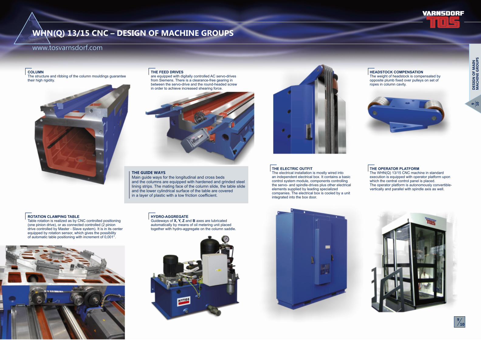
COLUMNThe structure and ribbing of the column mouldings guarantee their high rigidity.
ROTATION CLAMPING TABLETable rotation is realized as by CNC controlled positioning (one pinion drive), or as connected controlled (2 pinion drive controlled by Master - Slave system). It is in its center equipped by rotation sensor, which gives the possibility of automatic table positioning with increment of 0,001°.
THE GUIDE WAYSMain guide ways for the longitudinal and cross beds and the columns are equipped with hardened and grinded steel lining strips. The mating face of the column slide, the table slide and the lower cylindrical surface of the table are covered in a layer of plastic with a low friction coefficient.
THE FEED DRIVES are equipped with digitally controlled AC servo-drives from Siemens. There is a clearance-free gearing in between the servo-drive and the round-headed screw in order to achieve increased shearing force.
HEADSTOCK COMPENSATION The weight of headstock is compensated by opposite plumb fixed over pulleys on set of ropes in column cavity.
THE ELECTRIC OUTFITThe electrical installation is mostly wired into an independent electrical box. It contains a basic control system module, components controlling the servo- and spindle-drives plus other electrical elements supplied by leading specialized companies. The electrical box is cooled by a unit integrated into the box door.
HYDRO-AGGREGATEGuideways of X, Y, Z and B axes are lubricated automatically by means of oil metering unit placed together with hydro-aggregate on the column saddle.
THE OPERATOR PLATFORMThe WHN(Q) 13/15 CNC machine in standard execution is equipped with operator platform upon which the central control panel is placed. The operator platform is autonomously convertible-vertically and parallel with spindle axis as well.
www.tosvarnsdorf.com
WHN(Q) 13/15 CNC – DESIGN OF MACHINE GROUPS
DES
IGN
OF M
AIN
M
AC
HIN
E G
RO
UP
S

11
12
11
12
iTNC 530 HEIDENHAIN TT 140 measuring touch probe with cable transport
iTNC or Sinumerik 840D
HEIDENHAIN TS 220 measuring touch probe with cable transport
HEID. TS 640 + SE 640 measuring touch probe with optical transport RENISHAW OMP 60 - set measuring touch probe with optical transport RENISHAW RMP 60 - set measuring touch probe with wireless transport
M+H 20.41 Multi measuring touch probe with wireless transport
WE DELIVER THE FOLLOWING PROBES AS STANDARD:
WORKPIECE AND TOOL PROBES
RENISHAW TS 27 R
MEASURING TOUCH PROBE
measuring touch probe with cable transport
iTNC 530
iTNC orSinumerik 840D
MEASURING WORKPIECE PROBE for the system:
MEASURING TOOL PROBE for the system:
TOOL CONTROL PROBE
THE WHN(Q) 13/15 CNC MACHINE IS NORMALLY CONTROLLED BY THE HEIDENHAIN iTNC 530, SINUMERIK 840 D OR FANUC 31i CONTROL SYSTEM
TOSwide - the remote diagnostic system allows our service engineer to obtain required data about the status of the machine necessary to specify possible diagnostic messages about the non-standard condition of the machine's control system.
WE ALSO OFFER A SYSTEM OF SERVICES FOR THE PERMANENT SUPPORT OF CUSTOMERS:
TOSmessage - ensures communication between the machine's control system and the customer's mobile phone. The customer is informed about the predefined statuses of the machine, e.g. the completion of an automatic cycle or possibly program interruption.
PORTABLE CONTROL PANEL SINUMERIK
PORTABLE CONTROL PANEL HEIDENHAIN (OPTION TYPE HR 520)
All types of control systems in basic configuration consists of:• basic electronic module• collor LCD display unit• operational panel with keyboard• portable auxiliary control panel with an electronic handwheel.
In addition, control system functions and equipment may be equipped with:
• measuring touch probes
• network interface allowing remote diagnostics
All offered systems provide full control of 5 machine axes (X, Y, Z, W and B) plus spindle rotation (C).
An independent digital AC servo-drives applied with all convertible groups allow for simultaneous interpolation:
- linear - upto 5 axes - circular- helical
Option: continuously controlled B axis
CONTROL PANEL OF SINUMERIK 840 D CONTROL SYSTEM
CONTROL PANEL OF HEIDENHAIN iTNC 530 CONTROL SYSTEM
CONTROL PANEL OF FANUC 31i CONTROL SYSTEM
MA
CH
INE C
ON
TR
OLS
www.tosvarnsdorf.com
WHN(Q) 13/15 CNC – MACHINE CONTROL

111 222
Ø3
52
Ø430
Ø400
h7
Ø370
±0
35
460
110250
250 175
167 185
20
10
011
01
75
13
14
13
14
i
Facing head LD 650 ( ) or D´Andrea ( ) are used for demanding technological operations with the posibility 1 2of continuous CNC control of the slide position.
FACING HEAD
The HPR 50 and HUR 50 heads are used for machining the surfaces that are oriented in the basic direction (also generally) with regard to the orthogonal coordinate system of the machine.
The HUI 50 head is automatically indexed on both the planes with an increment of 2.5°, providing higher efficiency during the turning of the head spindle with regard to the orthogonal coordinate system of the machine.
MILLING HEADS
HPR 50 HUR 50
UFP 50-13universal milling head
FP 50-13vertical milling head
WHN(Q) 13/15 CNC – OPTIONAL ACCESSORIES
OP
TIO
NA
L A
CC
ES
SO
RIE
S
www.tosvarnsdorf.com
FASTENING OF MILLING HEADS
MANUAL FASTENINGManual fastening of the head on the machine is carried out by means of a lifting device.
HALF-AUTOMATIC FASTENINGThe head is fixed to the machine also in a half-automatic way from an auxiliary rack. The auxiliary rack is manually locked on hinged arms on the table.
HUI 50
www.tosvarnsdorf.cz/en/products/accessories/
ANOTHER OPTIONAL ACCESSORIES YOU CAN FIND ON
AUTOMATIC FASTENINGAutomatic fastening of the head (facing head) on the machine is carried out by means of an accessory magazine. Its execution is subject to prior consultation with the manufacturer.
CONNECTION PLACE
15
16
15
16
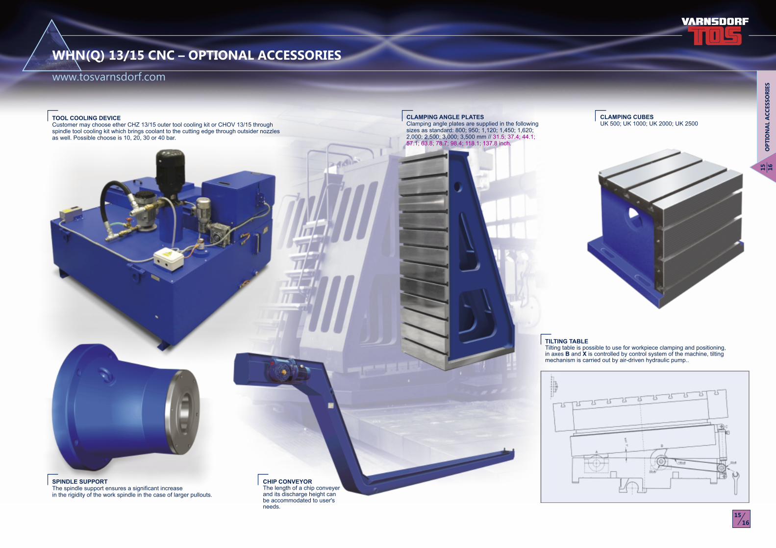
CHIP CONVEYOR The length of a chip conveyer and its discharge height can be accommodated to user's needs.
CLAMPING CUBESUK 500; UK 1000; UK 2000; UK 2500
CLAMPING ANGLE PLATES Clamping angle plates are supplied in the following sizes as standard: 800; 950; 1,120; 1,450; 1,620; 2,000; 2,500; 3,000; 3,500 mm // 31.5; 37.4; 44.1; 57.1; 63.8; 78.7; 98.4; 118.1; 137.8 inch.
SPINDLE SUPPORT The spindle support ensures a significant increase in the rigidity of the work spindle in the case of larger pullouts.
TOOL COOLING DEVICECustomer may choose ether CHZ 13/15 outer tool cooling kit or CHOV 13/15 through spindle tool cooling kit which brings coolant to the cutting edge through outsider nozzles as well. Possible choose is 10, 20, 30 or 40 bar.
WHN(Q) 13/15 CNC – OPTIONAL ACCESSORIES
OP
TIO
NA
L A
CC
ES
SO
RIE
S
www.tosvarnsdorf.com
TILTING TABLE Tilting table is possible to use for workpiece clamping and positioning, in axes B and X is controlled by control system of the machine, tilting mechanism is carried out by air-driven hydraulic pump..

17
18
17
18
a
b
c
X Y
WHN 13 CNC WHQ 13 CNC
X
Y
Z
bW
Y
Z
XB
a
c
WHN(Q) 13/15 CNC – MACHINE LAYOUT
MA
CH
INE L
AY
OU
T
www.tosvarnsdorf.com
Dimension
Machine weight
Table dimensions
Coordinate travel
DIMENSIONS AND WEIGHTS MACHINE LAYOUT
2,000 mm // 87.7 inch3,500 mm // 137.8 inch
5,000 mm // 196.9 inch
3,500 mm137.8 inch
2,500 mm98.4 inch
1,800 x 1,800 mm 70.9 x 70.9 inch
35,500 kg // 78,280 lbs 37,300 kg // 82,250 lbs
5,750 mm // 226.4 inch7,250 mm // 285.4 inch7,750 mm // 305.1 inch8,800 mm // 346.5 inch9,850 mm // 387.8 inch
4,000 mm // 157.5 inch
2,000 mm // 87.7 inch2,500 mm // 98.4 inch
3,500 mm // 137.8 inch
1,250 mm // 49.2 inch1,600 mm // 63 inch
3,200 mm // 126 inch
6,000 mm // 236.2 inch
3,000 mm // 118.1 inch
2,200 mm // 86.6 inch
MACHINE COVERSOn the customer's request we deliver following types of covers:
KVR CABIN protective covers for working space
MOBILE / MOVABLE protective partitions
C-COVER compact and technically advanced design
COMPLETE COVERING the top quality design without any residual risks
4,900 mm // 192.9 inch5,400 mm // 212.6 inch5,900 mm // 232.3 inch 6,400 mm // 252 inch
6,850 mm // 269.7 inch7,200 mm // 283.5 inch7,800 mm // 307.1 inch8,800 mm // 346.5 inch

19
20
19
20
WHN(Q) 13/15 CNC – TECHNOLOGIES
www.tosvarnsdorf.com
TEC
HN
OLO
GIE
S
MILLING AND BORING OF A CARRIAGES MILLING OF A CRANE ARM MILLING OF A VALVE FACE MILLING OF A HEAT EXCHANGER
DOUBLE-SIDED MILLING OF A CRANE ARM MILLING OF A CARRIAGE AXLE DRILLING OF A TUBE PLATE MILLING OF A FRONT ROLL FOR A ROADROLLER
PROPELLER HUB FOR A WIND-POWER STATION MILLING OF A STEAM TURBINE STATOR MILLING OF A DEEP WELL PUMP CRANKSHAFT IN ONE PIECE
MACHINING OF A GEARBOX PART FOR A LOGGING MACHINE
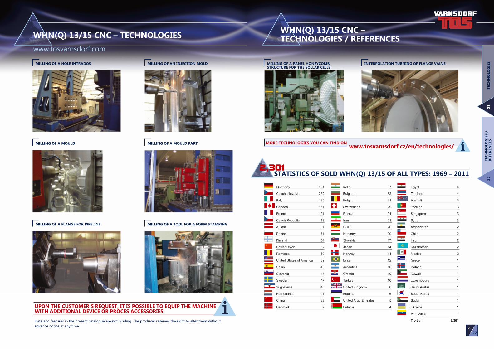
STATISTICS OF SOLD WHN(Q) 13/15 OF ALL TYPES: 1969 – 20112,301
Germany 381
Czechoslovakia 252
Italy 195
Canada 161
France 121
Czech Republic 118
Austria 91
Poland 71
Finland 64
Soviet Union 62
Romania 60
United States of America 59
Spain 48
Slovenia 47
Sweden 47
Yugoslavia 46
Netherlands 41
China 38
Denmark 37
India 37
Bulgaria 32
Belgium 31
Switzerland 29
Russia 24
Iran 21
GDR 20
Hungary 20
Slovakia 17
Japan 14
Norway 14
Brazil 12
Argentina 10
Croatia 10
Turkey 10
United Kingdom 6
Estonia 6
United Arab Emirates 5
Belarus 4
Egypt 4
Thailand 4
Australia 3
Portugal 3
Singapore 3
Syria 3
Afghanistan 2
Chile 2
Iraq 2
Kazakhstan 2
Mexico 2
Grece 1
Iceland 1
Kuwait 1
Luxembourg 1
Saudi Arabia 1
South Korea 1
Sudan 1
Ukraine 1
Venezuela 1
T o t a l 2,301
iMORE TECHNOLOGIES YOU CAN FIND ON www.tosvarnsdorf.cz/en/technologies/
WHN(Q) 13/15 CNC – TECHNOLOGIES
www.tosvarnsdorf.com
TEC
HN
OLO
GIE
S2
1T
EC
HN
OLO
GIE
S /
REFER
EN
CES
22
WHN(Q) 13/15 CNC – TECHNOLOGIES / REFERENCES
21
22
MILLING OF A HOLE INTRADOS MILLING OF AN INJECTION MOLD
MILLING OF A MOULD MILLING OF A MOULD PART
MILLING OF A FLANGE FOR PIPELINE MILLING OF A TOOL FOR A FORM STAMPING
INTERPOLATION TURNING OF FLANGE VALVEMILLING OF A PANEL HONEYCOMB STRUCTURE FOR THE SOLLAR CELLS
iData and features in the present catalogue are not binding. The producer reserves the right to alter them without
advance notice at any time.
UPON THE CUSTOMER'S REQUEST, IT IS POSSIBLE TO EQUIP THE MACHINE WITH ADDITIONAL DEVICE OR PROCES ACCESSORIES.

www.tosvarnsdorf.com
TOS VARNSDORF a.s.
Říční 1774, 407 47 Varnsdorf
Czech Republic
Germany
Poland
Austria
Slovakia
Praha
Brno
TOS VARNSDORF a.s.TOS VARNSDORF a.s.
TOS VARNSDORF a.s.
Phone: +420 412 351 203
Fax: +420 412 351 269
E-mail: [email protected]
www.tosvarnsdorf.com
www.tosvarnsdorf.eu


