Proceedings of the RINA 5th International Conference on Ship and Offshore Technology ICSOT 2017 December 7-8, 2017, IIT Kharagpur, India ICSOT2017-42 HORIZONTAL PLANAR MOTION MECHANISM (HPMM) INCORPORATED TO THE EXISTING TOWING CARRIAGE FOR SHIP MANOEUVRING STUDIES Akhil Balagopalan Department of Ocean Engineering Indian Institute of Technology, Madras Chennai, India. 600036 Email: [email protected]Kunal N. Tiwari Department of Ocean Engineering Indian Institute of Technology, Madras Chennai, India. 600036 Email: [email protected]P Krishnankutty Department of Ocean Engineering Indian Institute of Technology, Madras Chennai, India. 600036 Email: [email protected]ABSTRACT Planar Motion Mechanism (PMM) equipment is a facility generally attached with Towing Tank to perform experimental studies with ship models to determine the manoeuvring charac- teristics of a ship. Ship model is oscillated at prescribed am- plitude and frequency in different modes of operation while it is towed along the towing tank at predefined speed.The hydrody- namic forces and moments are recorded, analyzed and processed to get the hydrodynamic derivatives appearing in the manoeu- vring equations of motion of a ship. This paper presents the de- tails about the Horizontal Planar Motion Mechanism (HPMM) equipment which is designed, developed and installed in Towing Tank laboratory at IIT Madras. NOMENCLATURE r Yaw velocity. u Surge velocity. v Sway velocity. x E Position in x-direction. y E Position in y-direction. y a Sway amplitude. x s Distance between load cell mounting and midship. β Drift angle. ψ Euler angle for rotation about z-axis. ψ a Yaw amplitude. 1 INTRODUCTION Manoeuvring quality assessment for ships are essential for the navigational safety purpose.International Maritime Organisa- tion (IMO) has prescribed safety guidelines for the sea going ves- sels to ensure its navigational safety and operational efficiency. Manoeuvrability of ships depends on the and the effectiveness of rudder or other control devices.The accurate prediction of manoeuvring behaviour of the vessel has to be done at design stage itself. Directional stability and control characteristics of ship are understood by solving the manoeuvring equation of mo- tion, for which the knowledge of hydrodynamic derivatives are essential.The quality of manoeuvring behaviour prediction relies on the accuracy at which the hydrodynamic derivatives are es- timated. The hydrodynamic derivatives are usually determined by theoretical, numerical or experimental methods. Empirical relations provided by researchers such as M Hirano et al. [1], Kijima et al. [2] gives a rough estimate of the hydrodynamic derivatives but fails to predict non linear and coupled derivatives accurately. More reliable values can be obtained only by con- ducting captive model testings on ship models, of which Planar Motion Mechanism is the widely used one. Planar Motion Mech- anism (PMM) pioneered by Gertler and Goodman et al(1962) [3] is considered to be the major outbreak for captive model test- ings in ship manoeuvring area. Large amplitude planar motion mechanisms installed around the world in early years of 1980s provided much more enlightenment in ship motion predictions. PMM facility installed in a towing tank enable us to perform the dynamic tests in pure sway, pure yaw and combined sway and yaw modes of model oscillations. These dynamic tests provide 1 Copyright c 2017 by RINA
Transcript
Proceedings of the RINA 5th International Conference on Ship and Offshore TechnologyICSOT 2017
December 7-8, 2017, IIT Kharagpur, India
ICSOT2017-42
HORIZONTAL PLANAR MOTION MECHANISM (HPMM) INCORPORATED TO THEEXISTING TOWING CARRIAGE FOR SHIP MANOEUVRING STUDIES
Akhil BalagopalanDepartment of Ocean Engineering
Indian Institute of Technology, MadrasChennai, India. 600036
ABSTRACTPlanar Motion Mechanism (PMM) equipment is a facility
generally attached with Towing Tank to perform experimentalstudies with ship models to determine the manoeuvring charac-teristics of a ship. Ship model is oscillated at prescribed am-plitude and frequency in different modes of operation while itis towed along the towing tank at predefined speed.The hydrody-namic forces and moments are recorded, analyzed and processedto get the hydrodynamic derivatives appearing in the manoeu-vring equations of motion of a ship. This paper presents the de-tails about the Horizontal Planar Motion Mechanism (HPMM)equipment which is designed, developed and installed in TowingTank laboratory at IIT Madras.
NOMENCLATUREr Yaw velocity.u Surge velocity.v Sway velocity.xE Position in x-direction.yE Position in y-direction.ya Sway amplitude.xs Distance between load cell mounting and midship.β Drift angle.ψ Euler angle for rotation about z-axis.ψa Yaw amplitude.
1 INTRODUCTIONManoeuvring quality assessment for ships are essential for
the navigational safety purpose.International Maritime Organisa-tion (IMO) has prescribed safety guidelines for the sea going ves-sels to ensure its navigational safety and operational efficiency.Manoeuvrability of ships depends on the and the effectivenessof rudder or other control devices.The accurate prediction ofmanoeuvring behaviour of the vessel has to be done at designstage itself. Directional stability and control characteristics ofship are understood by solving the manoeuvring equation of mo-tion, for which the knowledge of hydrodynamic derivatives areessential.The quality of manoeuvring behaviour prediction relieson the accuracy at which the hydrodynamic derivatives are es-timated. The hydrodynamic derivatives are usually determinedby theoretical, numerical or experimental methods. Empiricalrelations provided by researchers such as M Hirano et al. [1],Kijima et al. [2] gives a rough estimate of the hydrodynamicderivatives but fails to predict non linear and coupled derivativesaccurately. More reliable values can be obtained only by con-ducting captive model testings on ship models, of which PlanarMotion Mechanism is the widely used one. Planar Motion Mech-anism (PMM) pioneered by Gertler and Goodman et al(1962) [3]is considered to be the major outbreak for captive model test-ings in ship manoeuvring area. Large amplitude planar motionmechanisms installed around the world in early years of 1980sprovided much more enlightenment in ship motion predictions.PMM facility installed in a towing tank enable us to perform thedynamic tests in pure sway, pure yaw and combined sway andyaw modes of model oscillations. These dynamic tests provide
the data for almost all the linear as well as non linear hydro-dynamic derivatives, both velocity and acceleration dependentones. The Fourier series representation of the force and momenttime histories recorded from the model during these tests leads tothe determination of the hydrodynamic derivatives. These hydro-dynamic derivatives can be used to simulate the vessel trajectoryto assess the manoeuvring quality of the ship.
This paper describes about the Planar Motion Mechanismsetup recently installed in the Towing Tank Laboratory of OceanEngineering Department, IIT Madras. Preliminary calculationof forces and moments in different PMM motions are estimatedduring the initial stage of design. After considerable study of thelimitations of the existing Towing Tank and Towing Carriage,PMM design parameter are determined. As the In house fabrica-tion of the mechanical and electronic components are not a viableoption, the fabrication of PMM setup was awarded to RockwellAutomation India Pvt. Ltd.
2 PMM Design Aspects
FIGURE 1. Towing Tank and Carriage
IIT Madras Towing Tank (Fig. 1) has a length of 83m,breadth 3.2m and depth 2.8m, which are used for different shipmodel testings. Towing carriage is of length 4m in length and3.75m in breadth and is capable of towing the ship model at amaximum speed of 5m/s. Four DC servo motors are connectedto each of the carriage wheels in series and are controlled byWard Leonard drive system. Towing carriage test well is of 3m x1.35m in dimension and is slightly off from the centre line of thetowing tank to accommodate the control consoles inside the car-riage. PMM design was formulated by considering these aspectsand are listed in Table 1.
S B
+v+y+Y
+x +u +X
+ψ +r +N
SWAY SURGEYAW
xs xs
FIGURE 2. Sign Conventions
TABLE 1. PMM Design parameters
Parameter Design consideration Maximumvalue
SwayAmplitude
1. Adequate clearance betweenship model and tank wall 380 mm
2. Minimum interaction withwall. [4]
AngularFrequency
1. Number of cycles in steadyspeed condition 2.5 rad/s
2. Minimum 4-5 cycles.
YawAmplitude
1. Adequate clearance betweenship model and tank wall 15◦
2. Minimum interaction withwall.
Model Size 1. Towing carriage test welllimitations. 4.5 m
2. Tank wall clearances.
3 Horizontal Planar Motion MechanismPMM is mechanism where ship model is held and subjected
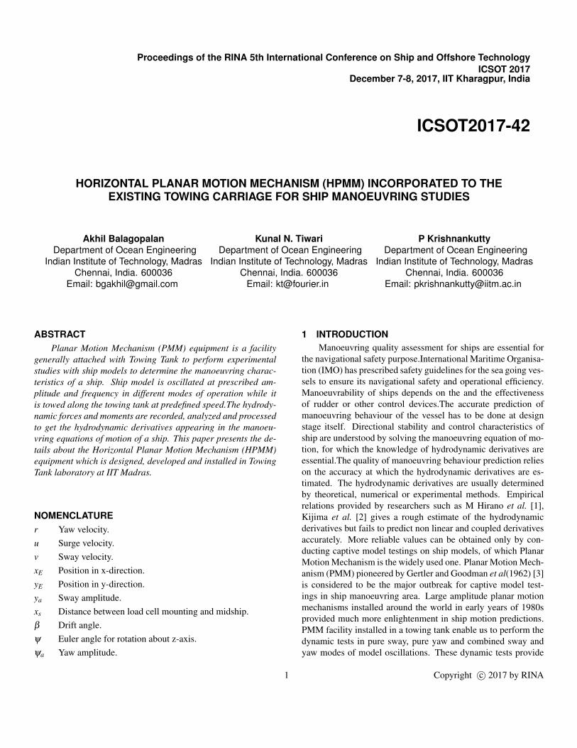
to specific harmonic motions while being towed along the lengthof towing tank. Traditionally two independent oscillators wereused to produce oscillations [5–7]. Due to space constrains inour towing tank, a different twin motor approach was considered.Two different motors are used to produce transnational motion iny0 direction and rotational motion with respect to z-axis respec-tively (refer Fig 5 and Fig. 4).
The block diagram of the PMM mechanism is given in Fig.3. Different motion felt by various components of mechanismis chalked out on the right side of the figure. Carriage, PMMbase frame and sway mechanism experience just surge motion.Yaw mechanism experiences sway motion along with the surge.Loadcell and ship model experience all the three forced modeof motion (surge, sway and yaw). It should be noted that shipmodel is free to pitch and heave. The flow of data is representedby means of blue lines. The communication between servo mo-tor and drive takes place through customised Allan-Bradly feed-back cable while those between drive, PLC for PMM, PLC forcarriage (existing system) and HMI (existing hardware with up-dated software) takes place through ethernet.
PMM uses a standard right handed coordinate system withx-axis (surge) is positive in the forward direction of carriagemovement, y-axis (sway)is positive to starboard relative to theforwards motion of the carriage and z-axis (heave) pointingdownwards (into the paper). Rotation around the z-axis (Yaw) ispositive for rotation to starboard, clockwise when looking downon the model with bow pointing in the forward direction of thecarriage movement (refer Fig. 2 for clarity).
3.1 Pure SwayIn pure sway mode of operation, the model is oscillated si-
nusoidally in the lateral direction with its axis always parallel tothe axis of the towing tank while it is moving forward with aspecified speed (Fig 6). This motion is generated by keeping theangular motor locked and subjecting transnational motion motorto follow cosine motion as follows,
yE = ya cos(ωt) (1)ψE = 0◦ (2)
This ensures that yaw velocity and yaw acceleration arezero; the forces measured will be resulting due to sway motionalone.
The linear or sway motion is achieved in PMM setupthrough the servomotor and with a lead screw mechanism. Ser-vomotor is attached to the lead screw using a belt drive arrange-ment. When the linear motor rotates, the slide plate arrangement,which includes rotational bevel gear and vertical shaft, move toand fro transversely through the linear guide (refer Fig. 7). Thelinear motion will be transmitted to the ship model through thePMM arms, which is connected to the ship model.
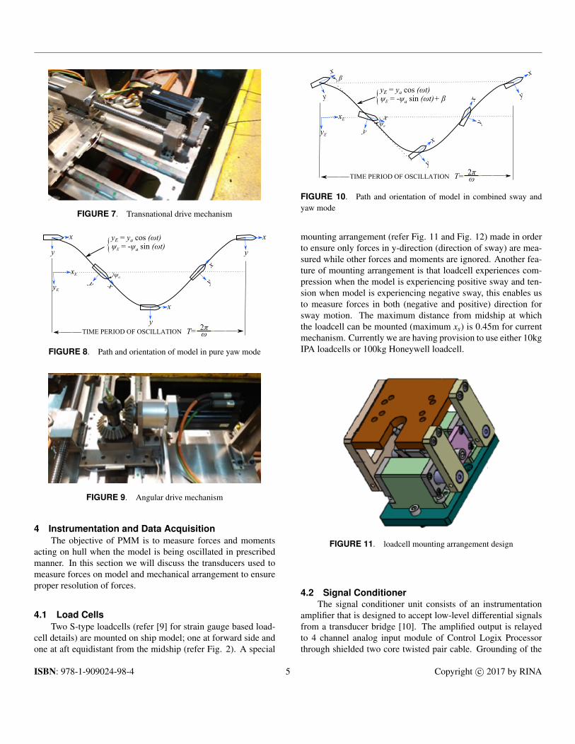
3.2 Pure YawIn pure yaw mode of operation, the model is oscillated sinu-
soidally in the lateral direction with its axis always tangential tothe sinusoidal path while it is moving forward with a specifiedspeed (refer Fig. 8). The idea is to ensure sway velocity andacceleration is zero. The cam points required for this mode aregenerated using,
yE = ya cos(ωt) (3)ψ = −ψa sin(ωt) (4)
The rotary or yaw motion is achieved through a centrallymounted gear mechanism. The bevel gear assembly with pinionis mounted on the linear motion slide plate assembly through acentral vertical shaft (Fig. 9). The assembly is provided withthrust bearings and end supports. Servomotor is attached withthe bevel gear mechanism by using fixtures. Use of cosine func-tion for translation motion motor (as opposed to sine functionused traditionally [5–8]) ensures that jerk at start of the motion isminimized.
3.3 Combined ModeIn the combined sway and yaw mode of operation, the model
is oscillated sinusoidally in the lateral direction with its axis al-ways having a prescribed drift angle along the sinusoidal path
FIGURE 5. Ship model attached to PMM setup
x
y
x
y
x
y
x
y
x
y
TIME PERIOD OF OSCILLATION T= 2πω
y = y0 cos (ωt)
FIGURE 6. Path and orientation of model in pure sway mode
while it is moving forward with a specified speed (refer Fig. 10).The cam points required for this mode are generated using,
FIGURE 8. Path and orientation of model in pure yaw mode
FIGURE 9. Angular drive mechanism
4 Instrumentation and Data AcquisitionThe objective of PMM is to measure forces and moments
acting on hull when the model is being oscillated in prescribedmanner. In this section we will discuss the transducers used tomeasure forces on model and mechanical arrangement to ensureproper resolution of forces.
4.1 Load CellsTwo S-type loadcells (refer [9] for strain gauge based load-
cell details) are mounted on ship model; one at forward side andone at aft equidistant from the midship (refer Fig. 2). A special
x
y
x
y
x
y
xy
x
y
TIME PERIOD OF OSCILLATION T= 2πω
yE = ya cos (ωt)
xE
yE
ψE = -ψa sin (ωt)+ β {
ψa
β
FIGURE 10. Path and orientation of model in combined sway andyaw mode
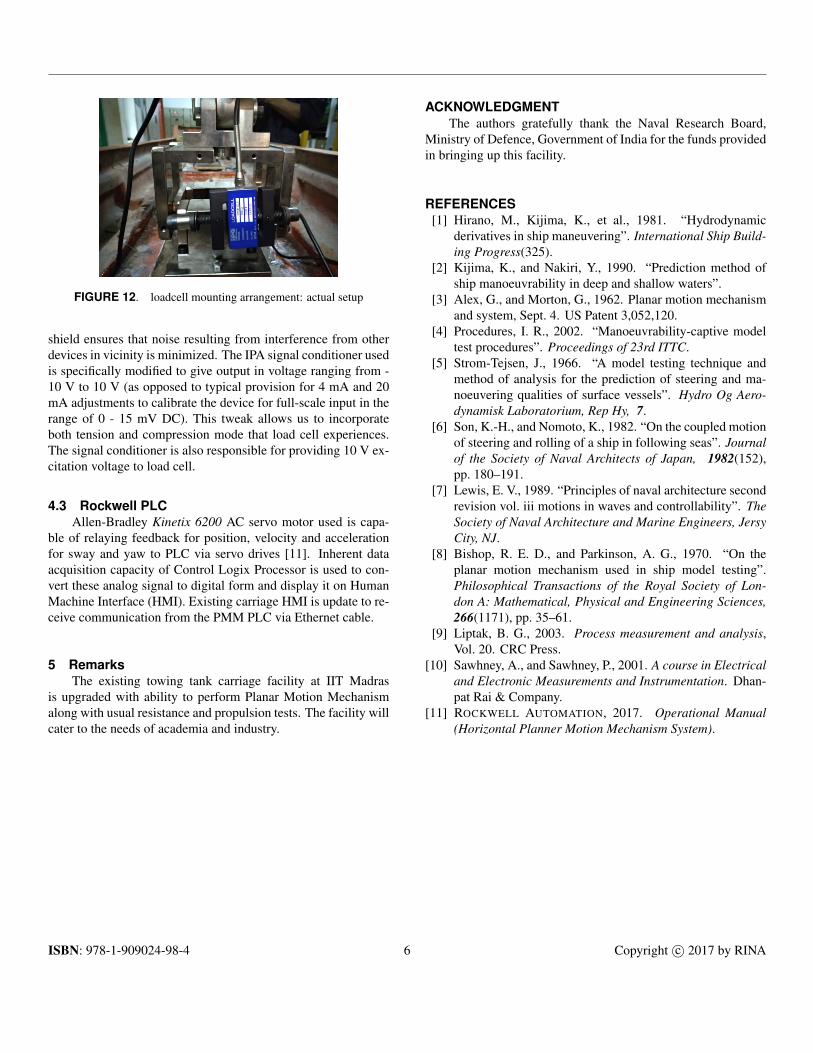
mounting arrangement (refer Fig. 11 and Fig. 12) made in orderto ensure only forces in y-direction (direction of sway) are mea-sured while other forces and moments are ignored. Another fea-ture of mounting arrangement is that loadcell experiences com-pression when the model is experiencing positive sway and ten-sion when model is experiencing negative sway, this enables usto measure forces in both (negative and positive) direction forsway motion. The maximum distance from midship at whichthe loadcell can be mounted (maximum xs) is 0.45m for currentmechanism. Currently we are having provision to use either 10kgIPA loadcells or 100kg Honeywell loadcell.
FIGURE 11. loadcell mounting arrangement design
4.2 Signal ConditionerThe signal conditioner unit consists of an instrumentation
amplifier that is designed to accept low-level differential signalsfrom a transducer bridge [10]. The amplified output is relayedto 4 channel analog input module of Control Logix Processorthrough shielded two core twisted pair cable. Grounding of the
FIGURE 12. loadcell mounting arrangement: actual setup
shield ensures that noise resulting from interference from otherdevices in vicinity is minimized. The IPA signal conditioner usedis specifically modified to give output in voltage ranging from -10 V to 10 V (as opposed to typical provision for 4 mA and 20mA adjustments to calibrate the device for full-scale input in therange of 0 - 15 mV DC). This tweak allows us to incorporateboth tension and compression mode that load cell experiences.The signal conditioner is also responsible for providing 10 V ex-citation voltage to load cell.
4.3 Rockwell PLCAllen-Bradley Kinetix 6200 AC servo motor used is capa-
ble of relaying feedback for position, velocity and accelerationfor sway and yaw to PLC via servo drives [11]. Inherent dataacquisition capacity of Control Logix Processor is used to con-vert these analog signal to digital form and display it on HumanMachine Interface (HMI). Existing carriage HMI is update to re-ceive communication from the PMM PLC via Ethernet cable.
5 RemarksThe existing towing tank carriage facility at IIT Madras
is upgraded with ability to perform Planar Motion Mechanismalong with usual resistance and propulsion tests. The facility willcater to the needs of academia and industry.
ACKNOWLEDGMENTThe authors gratefully thank the Naval Research Board,
Ministry of Defence, Government of India for the funds providedin bringing up this facility.
REFERENCES[1] Hirano, M., Kijima, K., et al., 1981. “Hydrodynamic
derivatives in ship maneuvering”. International Ship Build-ing Progress(325).
[2] Kijima, K., and Nakiri, Y., 1990. “Prediction method ofship manoeuvrability in deep and shallow waters”.
[3] Alex, G., and Morton, G., 1962. Planar motion mechanismand system, Sept. 4. US Patent 3,052,120.
[4] Procedures, I. R., 2002. “Manoeuvrability-captive modeltest procedures”. Proceedings of 23rd ITTC.
[5] Strom-Tejsen, J., 1966. “A model testing technique andmethod of analysis for the prediction of steering and ma-noeuvering qualities of surface vessels”. Hydro Og Aero-dynamisk Laboratorium, Rep Hy, 7.
[6] Son, K.-H., and Nomoto, K., 1982. “On the coupled motionof steering and rolling of a ship in following seas”. Journalof the Society of Naval Architects of Japan, 1982(152),pp. 180–191.
[7] Lewis, E. V., 1989. “Principles of naval architecture secondrevision vol. iii motions in waves and controllability”. TheSociety of Naval Architecture and Marine Engineers, JersyCity, NJ.
[8] Bishop, R. E. D., and Parkinson, A. G., 1970. “On theplanar motion mechanism used in ship model testing”.Philosophical Transactions of the Royal Society of Lon-don A: Mathematical, Physical and Engineering Sciences,266(1171), pp. 35–61.
[9] Liptak, B. G., 2003. Process measurement and analysis,Vol. 20. CRC Press.
[10] Sawhney, A., and Sawhney, P., 2001. A course in Electricaland Electronic Measurements and Instrumentation. Dhan-pat Rai & Company.