Insul-8 Mobile Electrification ◆ Cable & Hose Reels ◆ Conductor Bar ◆ Festoon ◆ Pendants ◆ ◆ Radio Controls ◆ Slip Rings ◆ Solutions From A Single Source Hose Reels Hose Management Systems For Hose Management of: ● Manufacturing ● Automotive Service Centers ● Fleet Line ● Material Handling
Transcript
Insul-8 Mobile Electrification◆ Cable & Hose Reels ◆ Conductor Bar ◆◆ Festoon ◆ Pendants ◆
◆ Radio Controls ◆ Slip Rings ◆
Solutions From A Single Source
Hose ReelsHose Management Systems
For Hose Management of:●● Manufacturing●● Automotive Service Centers●● Fleet Line●● Material Handling
Page 1(800) 521-4888
Don’t see what you need? Call us!www.insul-8.com
Header Text
Information subject to change without notice
Sub Header Text
Specifications may change without notice. All products F.O.B. Omaha, NE, or Harlan, IA, unless otherwise specified.
Industrial Electric Reels, Inc., began in 1924 with the founding of Industrial Electric Works (IEW), an electrical contractor based in Omaha, Nebraska. After World War II,IEW began the manufacture of electric cable reeling equipment and started IER as an operating division in 1948.IER’s first cable reel, the hand rewind Series 102 PORT-O-REEL, was quickly followed by light-duty springretractable cable reels. IER pioneered the development ofcable reeling devices and slip rings. Soon the businessexpanded to larger, custom built motor driven reels and custom engineered slip rings. IER’s reputation spread as a quality manufacturer of reels running the gamut from small commercial duty reels to large custom built reels for the mostdemanding applications such as container cranes,stacker/reclaimers and bulk material ship loaders and unloaders.Insul-8 Corporation has been a pioneer in providing safety-covered metal conductor systems for the material handling industry since 1944. Insul-8 was the first company to design and produce a stainless steel capped aluminum conductor and the only manufacturer of such a product for almost 20 years. Today, there are over 20 millionmeters (nearly 12,500 miles) of Insul-8 contact conductors and tens of thousands of collecting devices throughout the world.Every major port in the United States currently uses Insul-8’s aluminum/stainless steel contact conductors on container cranesdue to the dependability of the bar under the most severe conditions. Insul-8’s festoon systems range from the smallest box-tracksystems to our most rugged Heavy-Duty Festoon. Insul-8’s festoons are known for their safe and efficient operation in which largenumbers of conductors can be handled in minimum space.
Insul-8 has been in the business of supplying power from stationary sources to mobile systems for 60 years. Insul-8’s cable reels,slip rings, conductor bar, festoon systems, pendants and radio controls are used in a wide variety of applications ranging from material handling and mass transit systems to water treatment plants and performing arts theaters.As it has been for the last 60 years and always will be, “conducting” business will continue to be our only business.
Since our inception in 1902, Insul-8 Corporation’s parent company,Delachaux S.A., has been a leading international presence in the business of providing mobile electrification. As the Delachaux arm inNorth and South America, Insul-8 Corporation (formerly sister companies Insul-8 and Industrial Electric Reels, Inc. - a.k.a. IER) carrieson this tradition of innovation and excellence. Insul-8 and IER becamepart of the Delachaux Group in 1975 and officially became one compa-ny on December 31, 1996. Each company has its own rich history.
You’ll find Insul-8 products in use everywhere from irrigation systems and manufacturingplants in the heartland of the United States to public transportation systems in Malaysia.
Insul-8 products can electrify items from small industrial machinery to large
amusement park rides and international public transit systems.
In December 1997, after a nine month endeavor, Insul-8 Corporation became ISO 9001 certified for the design and manufactureof our entire line of mobile electrification products in both of our U.S.A. plants in Omaha, Nebraska, and Harlan, Iowa.
◆ cable and hose reels ◆ conductor bar systems ◆ cable festoon systems ◆◆ slip rings ◆ pendant stations ◆ radio controls ◆www.insul-8.com
Page 2(800) 521-4888www.insul-8.com
Table of Contens
Don’t see what you need? Call us!Information subject to change without notice
Hose Reel Basics........................................................ 3-6Components of a Hose Reel.............................................................................3How to Select the Reel......................................................................................4Why do you need a Hose Reel.........................................................................4How to order a Hose Reel.................................................................................4
Air / Water....................................................................... ....................................9Oxygen / Accetylene / Hydraulic....................................................................10
Part Number Decoders.................................................11Hose Reel Dimensions............................................12-14
1400 Series.................................................................. .................................... 12D, E, & F Series 19” Reel.................................................................................12D, E, & F Series 24” & 32” Reels.....................................................................13H Series (One Motor).......................................................................................14H Series (Two Motor).......................................................................................14
Hand Wound Reels.......................................................25
Page 3(800) 521-4888
Don’t see what you need? Call us!www.insul-8.com
Hose Reel Basics
Information subject to change without notice
Components of A Hose Reel
Swivel & ElbowAssembly
Optional BallStop
Swivel Enclosure (Cover not used on all models)
Entrance RingSpool Drum
Flange
Base (aka Frame / Stand)
Ratchet(Optional)
RollerGuide
Spring Motor
(Typical Powereel Series Portrayed)
Five Basic Parts
Base/Stand Supports and mounts the reel.
Spring Motor Motor which rotates the spool.
SpoolComposed of a drum and twoFlanges.
SwivelTransfers fluid/gas from a fixedsource through a rotating source.
Roller GuideGuides the hose during payoutand rewind.
Definition of Terms
ActiveLength
The difference between the minimum andmaximum payout of hose. (See “Payout” below.)
Safety WrapHose that stays on the reel at maximumpayout (Usually 2 complete wraps.)
Sag FactorThe effect of gravity on actual travel lengthduring stretch applications. (6%-10%)
Lift HeightThe distance between where the hose laysto the center line of the spool.
Payout Pulling hose out of the reel.
Retract orRewind
Rewinding hose back into the reel.
Page 4(800) 521-4888www.insul-8.com
Hose Reel Basics
Don’t see what you need? Call us!Information subject to change without notice
How to Select the Right Hose Reel
Why do you need a Hose Reel?
How to Order a Hose Reel
In order to use the Hose Reel Selection Chart, first determine your mechanical, electrical and hose length requirements. Follow these three steps to make sure you get the best reel for your application needs. Your local representative or the sales team at our factory are glad to help if you need additional assistance.
Step 1 - Mechanical Requirements:
● How will the reel be used? Stretch, Lift, Drag or Retrieve? ● What type of environment will the reel be located in?
(indoors, outdoors, corrosive environment.)● What is the duty cycle? (How often will the reel payout and Retract?)● What is the maximum speed of equipment? (Maximum
● How much PSI will the hose reel be expected to handle.● What will the reel be required to handle: air/water?● What hose ID is required?
(For assistance, please refer to Hose Data Charts on pages 5 & 6.)
Step 3 - Hose Length Requirements:
Add: Active Length - The difference between the minimum and maximum operating payout.
Plus: Inactive Length - Hose that always stays out of the reel, even at full retraction.
Plus: SafetyWrap✱ - Hose that stays on the reel a maximum payout. - See note below for details.
Plus: Sag Factor (Stretch Only) - Add 10% to Acttive and Inactive Length total.
Plus: Lift height (Drag/Retrieve) - The distance between where the hose lays up to the spool center line. Max 4’.
Plus: Hook up Length - Hose required for termination at both ends - 2-3’ on spool end.
✱✱Note: 1400 Series = 2’, 1900/2400 Series = 5’, D,E,F & H Series = 5-7’, HW 20/30 = 2’, and HW40 = 5’
Stretch
The hose is “stretched” horizontally and is unsupported. The reelmay be stationary mounted or mounted onto moving equipment.Hose is pulled out by machine. An extra 6% - 10% in hose beyondactive travel is required for hose sag.
Drag
The reel needs to “drag” the hose through supports or along theground horizontally. The reel is usually stationary. Hose can bepulled out by hand or by machine. Note: This application is hardeston hose life.
Lift
The reel needs to “lift” the hose vertically. The reel is usually station-ary. Hose is pulled out of the reel by machine or by hand (as with an overhead supply source.)
• Make Shop, Garage or Other Work Areas Safer: A hose left on the ground can be tripped over by employees or customers, potentially causing serious injury. The 1400 Series Hose Reel keeps hose neatly stored and ready to use.
• Eliminates Hose Handing Problems: Save time and increase efficiency. Grab the hose and go. It’s just as easy to reel in. Remember: The 1400 Series hose reel is 100% spring retractable.
• Extend Hose Life: Save time and money. Reduces costly repairs and downtime when hoses are damaged while left on the ground.
Determine the following:1) What will you put through the hose (air, water, etc)?2) What is the maximum pressure (in P.S.I.) needed for
operation?3) How will you be using the hose? (Will it be stretched,
lifted/dragged or retrieved?)
4) How far out will the hose need to retract?5) Is a ball stop required for the application?6) Is an inlet hose assembly needed to connect hose
reel and source of supply? (Highly recommended.)
Page 5(800) 521-4888
Don’t see what you need? Call us!www.insul-8.com
Determining Hose Requirements
Information subject to change without notice
Hose Data
Hose Data - Air/WaterModified vinyl w/two textile spirals & rubber modified non marking thermoplastic cover.
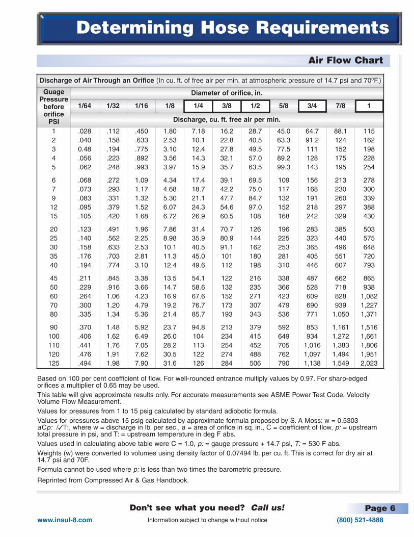
Based on 100 per cent coefficient of flow. For well-rounded entrance multiply values by 0.97. For sharp-edged orifices a multiplier of 0.65 may be used.This table will give approximate results only. For accurate measurements see ASME Power Test Code, Velocity Volume Flow Measurement.Values for pressures from 1 to 15 psig calculated by standard adiobotic formula.Values for pressures above 15 psig calculated by approximate formula proposed by S. A Moss: w = 0.5303 aCp: /✓T:, where w = discharge in lb. per sec., a = area of orifice in sq. in., C = coefficient of flow, p: = upstreamtotal pressure in psi, and T: = upstream temperature in deg F abs.Values used in calculating above table were C = 1.0, p: = gauge pressure + 14.7 psi, T: = 530 F abs.Weights (w) were converted to volumes using density factor of 0.07494 lb. per cu. ft. This is correct for dry air at 14.7 psi and 70F.Formula cannot be used where p: is less than two times the barometric pressure.
Reprinted from Compressed Air & Gas Handbook.
Page 7(800) 521-4888
Don’t see what you need? Call us!www.insul-8.com
Determining Hose Requirements
Information subject to change without notice
Celsius / Farenheit
Metric Conversion
Temperature Conversion Table1. Locate known temperature in OC/OF Column.2. Read converted temperature in OC or OF Column.
For quick and easytemperature conversion,please use theCelsius / Farenheitcrossover chartprovided above.
To Obtain MultiplyMillimeters Inches x 25.4
Inches Millimeters x 0.0394
Meters Feet x .3048
Feet Meters x 3.281
Square Centimeters Square Inches x 6.45
Square Inches Square Centimeters x 0.155
Kilograms Pounds x 0.4536
Pounds Kilograms x 2.205
Pounds Per Suare Inch Bars x 14.5
Page 8(800) 521-4888www.insul-8.com
Hose Reel Descriptions
Don’t see what you need? Call us!Information subject to change without notice
About our Hose Reels
Series 1400 Hose Reels are designed for 100% unassisted spring retention using direct drive (1:1 ratio) canisterized spring motor. These reels willaccomidate up to 60’ lengths up to 300 PSI Air/Water hose.Reel Features: Indoor/Outdoor use. Life time lubricated spring cartridge, ruggedfabricated steel construction, durable safety yellow polyurethane powder coating,ratchet assembly (easy disengagement for constant tension requirements), 12 position 4-roller hose guide.
Series 1900 - 4200 Hose Reels are designed for 100% unassisted spring retention using direct drive (1:1 ratio) canisterized spring motor. These reels willaccomidate up to 100’ lengths up to 300 PSI Air/Water hose with 1/4” to 1.0”I.D.’s Reel Features: Indoor/Outdoor use. Life time lubricated spring cartridge,rugged fabricated steel construction, durable safety yellow polyurethane powdercoating, 12 position 4-roller hose guide.
SERIES D, E and F Hose Reels are designed using a direct drive (1:1 ratio)spring motor. These reels will accommodate up to 100' lengths up to 300 P.S.I.Air/Water hose. Reel features: Indoor/Outdoor use. Rugged fabricated steel construction, Durable gray Epoxy finish. Adjustable 4 roller hose guide & Guiderails.Options: Ratchet, Stainless steel fasteners, 330 degree pivots, 360 degree continuous swivels. Marine duty (IEEE-45) USCC ABS, & Spool lock.Customizing available.
Series H Hose Reels are designed using spring motor with a variety of driveratios. These reels will accommodate up to 100' lengths up to 300 P.S.I.Air/Water hose. Reel features: Indoor/Outdoor use, Rugged fabricated steel construction, Durable gray Epoxy finish, Adjustable 4 roller guide & Guide rails.Options: Stainless steel fasteners, 330 degree pivots, Spool lock, Mill duty &Marine duty (IEEE-45) USCC ABS. Customizing available.
Series 1900 - 4200 Dual Hydraulics or OXY/ACC Hose Reels are designed for100% unassisted spring retention using direct drive (1:1 ratio) canisterized springmotor. These reels will accomodate up to 100’ lengths up to 5000 PSI Air/Waterhose with 1/4”, 3/8” & 1/2” I.D.’s. Reel Features: Indoor/Outdoor use. Lifetimelubricated spring cartridge, rugged fabricated steel construction, durable safetyyellow polyurethane powder coating, 12 position 4-roller hose guide.
Series 20-40 Hand Rewind Reels available in portable and stationary design.
(*) Available preassembled with hose i.e. 147250003011 includes 30 feet of .25” hose. Ratchets are standard on1400 (aka P-Series) with lock out feature, optional on all other Models except H Series hose reels. D, E, F & Hmodels available with marine duty option. “H” reels available with quick change spring motor w/ tensioner.Lift and Drag applications require an additional 5 feet of hose for hook up and safety wrap.Stretch application will require hose footage consisting of active travel plus 10% and additional 5’ for sag/hookup/safety wrap.No installation charge on hose purchased from Insul-8.
Page 10(800) 521-4888www.insul-8.com
Hose Reels Selection Chart
Don’t see what you need? Call us!Information subject to change without notice
Don’t see what you need? Call us!Information subject to change without notice
Cont. Series H - One Motor
Series H - Two Motor
Continued from Page 13
36” Flange
CatalogNo.
Dimensions Inches (mm) Weightlbs. (kg.)NPT A B C E F G H J K
HF41CH16DA
1
30 (762)85/8(219) 6 (153)
383/4(985)
205/8(524)
40(1016)
22(559)
161/8 (410)
6(153)
323 (147)
HF51DH16DA 327/8 (835)19 (483)
349 (159)
HT51FH16DA 323/8 (823)
83/8 (213) 51/2 (140)
350 (159)
HT61GH16DA351/4 (896) 217/8 (556)
378 (172)
HT61HH16DA 380 (173)
HV51EH16DA 343/8 (874)
93/8 (239) 71/2 (191)
19 (483) 355 (161)
HV71FH16DA 40 (1016) 245/8 (616) 81/8(204)
411 (187)
HV81JH16DA 427/8 (1089) 271/2 (699) 455 (207)
36” Flange
Catalog No.
Dimensions Inches (mm) Weightlbs. (kg.)NPT A B C E F G H J K
HT42DH16DA
1
291/2 (750)83/8 (213) 51/4 (140)
383/4(985)
205/8(524)
40(1016)
22(559)
161/8 (140)
6(153)
460 (209)
HT52EH16DA 323/8 (823) 19 (483) 514 (233)
HV42CH16DA 311/2 (801)
93/8 (239) 71/2 (191)
161/8 (410) 469 (214)
HV52DH16DA 343/8 (874) 19 (483) 521 (237)
HV62FH16DA 371/4 (947) 217/8 (556) 575 (261)
HV72GH16DA 40 (1016) 245/8 (626) 629 (286)
Page 15(800) 521-4888
Don’t see what you need? Call us!www.insul-8.com
Hose Reel Options
Information subject to change without notice
Quick Reference Chart
Options are detailed on pages 17 to 25 in alphabetical order. Use the chart below to find the entire range ofoptions available for each type of reel in the Insul-8 Hose Reel Family. On certain series of reels, we alreadyinclude some traditional “add-on” options as standard features of the base reel. For your convenience, the chartlists each series of reel, the option, the status (S = Standard, A = Add-On, “*” = on selected models only) andpage number detailing each option. Options for any Specialty Reels (pages 17 to 25) not already listed beloware the same as the reel from which it is modified. Please call if you need additional help.
Option
Ball S
top Pg:16
Guide R
ails
Hose G
rip Pg:16
Limit S
witch P
g:17
Marine D
uty Pg:17
Mill D
uty Pg:17
Pivot B
ase Pg:18
Quick C
hange Motor P
g:19
Ratchet P
g:20
Reel S
afe Pg:20
Roller G
uide Pg:21-23
Spool Lock
Sw
ivel Base 360
OP
g:24
1400 Series A A A S A S A
1900 - 2400Series A A A A A A A S A A
3200 - 3600 Series A S A A A S A A S A
D, E, FSeries A S A A A A A A S A A
H Series A S A A A A A A A✱✱ A S A
Hand Rewind A A
Page 16(800) 521-4888www.insul-8.com
Hose Reel Options
Don’t see what you need? Call us!Information subject to change without notice
Ball Stops
Hose & Cable Grips
Inlet Hose Assemblies
Ball Stops are also commonly referred to as “cable stops,” “bumper stops” or even “hose stops.”
● Generally used for manually operated lift and drag applications to govern retraction length.Stops are required when accessories such as air guns and drills are installed on hose reels.
● Suitable for all Insul-8 Hose Reels. (Less hand wound and dual hose.)● To order, use the following catalog numbers:
ROUND BALL STOP (Traditional) (Use with 1400 Series Only)
Cat. #34885 For hose O.D. ranging from 0.188" to .438" (with Shock Absorbing Spring Bumper)
Cat. #40006 For hose O.D. ranging from 0.188" to .438"(Without Shock Absorbing Spring Bumper)
FLAT DESIGN (Split Doughnut) (Suitable for 1400, D, E, F & H Series)
Cat. #34474 For hose O.D. ranges 0.438" to .624"Cat. #34475 For hose O.D. ranges 0.625" to .749"Cat. #34476 For hose O.D. ranges 0.750" to 1.05"Cat. #34477 For hose O.D. ranges 1.06" to 1.38"Cat. #34490 For hose O.D. ranges 1.39" to 1.55"
Hose & Cable Grips, also known as “strain reliefs,” are designed to relieve the concentrated strain onhose & cable terminations.◆ Generally used for reels in stretch applications◆ Suitable for all Insul-8 Hose Reels◆ To order, use following catalog numbers:
Cat. #03622 For hose O.D. ranges 0.430" to 0.610"Cat. #03623 For hose O.D. ranges 0.611" to 0.740"Cat. #03624 For hose O.D. ranges 0.741" to 0.990"Cat. #03625 For hose O.D. ranges 0.991" to 1.24"Cat. #03626 For hose O.D. ranges 1.25" to 1.49"
Inlet hose assemblies include male NPT fittings.#100448A 1/4" ID x 2' – 300 PSI
For ease of installation, use a flexible hose connection with swivel between the hosereel inlet and the source of supply to prevent possible misalignment and binding.
Page 17(800) 521-4888
Don’t see what you need? Call us!www.insul-8.com
Hose Reel Options
Information subject to change without notice
Limit Switches
Marine Duty Option
Mill Duty Option
Limit switches are used when an electrical interlock between hose payout length and other equipment is required. Rotary cam type limit switches are provided which are adjustable for accurate location of the tripping mechanism. A variety of internal gear ratios are available so that the selection of the properratio will give maximum rotation of the actuator. The standard limit switch consists of a 2-element switch to provide 2NO (normally open) and 2 NC (normally closed) sets of contacts in a NEMA 4 enclosure.
● Ideal for overrun control on overhead cranes and pendant reels.
● Suitable for D, E, F & H Series Reels.● To order, simply add “LS” at the end of the cable reel part number.
(Part Number Example: Standard ‘FECH12B’ with Option ‘FECH12BLS’)
Marine Duty option is available for reels used in applications around bodies of water and other moist envi-ronments as defined by marine specifications IEEE-45, US Coast Guard, ABS.
● Ideal for shipping ports, water treatment plants and other extremely moist areas.
● Suitable for D, E, F & H Series Reels.● To order, simply add “MA” at the end of the cable reel part number.
(Part Number Example: Standard ‘FECH12B’ with Option ‘FECH12BMA’)
Mill Duty option consists of heavy gauge steel, cast steel end-bells, external spring tension adjustors withQuick Change Motor option, reinforced guide rails with supports and lifting eyes.
● Ideal for reels used in mills and refineries operating in severe environments and demanding applications.
● Suitable for H Series Reels● To order, specify “MD” at the end of the cable reel part number.
(Part Number Example: Standard ‘FECH12B’ with Option ‘FECH12BMD’)
Page 18(800) 521-4888www.insul-8.com
Hose Reel Options
Don’t see what you need? Call us!Information subject to change without notice
Pivot Bases
Pivot Bases allow the cable reel to pivot back and forth (< 3600 ), for alternate directions of cable payout.Where cable payout exceeds 150 away from parallel to the spool, a pivot base should be used.(Note that “Swivel Bases” are available for applications that require a full 3600 pivot - see page 38). Pivot Bases areordered based on the specific style of reel used:
Reel Type Max. Rotation Weight Catalog No.
1400 Series 345O 7.5 lbs. PVB
1400 Series Torque Reel 360O 7.5 lbs. TRPVB
1500 Series 345O 20 lbs. XPVB
1900 / 2400 Series 330O 43.0 lbs. 40274A(E, G, H, J spools, E or L springs)
1900 / 2400 Series 330O 43.0 lbs. 40274B(E, G, H, J spools, F springs)
1900 / 2400 Series 330O 43.0 lbs. 40274C(F, K, L, M spools E, L or F springs)
D - E - F Series 330O 44.0 lbs. P2✱✱
For ✱✱, use the alpha characters designating the flange diameter and the width between flanges - see part number decoder on page 19.Example: Reel ECB34B uses a P2BC pivot base. For Hazardous Duty add “x” to the end of the Part No. Ex: (P2BCX)
H Series 330O 103.0 lbs. P3-H✱
For Hazardous Duty add “x” to the end of the Part No. Ex: (P3-H✱X)
For ✱, use the alpha characters designating the width between flanges - see catalog page 23. Example: HC31A34B
6 1/2 (17)
8 (20)
4 MTG. HOLESFOR 5/8" BOLTS
RISERS REQ’D.ON 1900-2400 REELS ONLY
REEL FRAME (REF.)
5 3/8 (14)
6 1/2 (17)
8 (20)
12 (30)
5 3/4(15)
4 MNT’G HOLESFOR 5/8" BOLTS
12 (30)
10 1/2 (26)
5.00
0.99
0.38
4 MTG. HOLESFOR 5/8" BOLTS
PVB or TRPVB
P2✱✱✱✱, 40274✱✱
or P2✱✱✱✱XP3 - H✱✱ and P3-H✱✱X
10 1/2 (26)
5 3/8 (14)
Page 19(800) 521-4888
Don’t see what you need? Call us!www.insul-8.com
Hose Reel Options
Information subject to change without notice
Quick Change Motor & External Tension Adjustment
Standard Series H reels are furnished with outboard spring motors that are connected directly to the reel spool with roller chain and sprocket drive.The optional quickchange spring motor can be supplied affording the user fast removal of the springmotor without disassembling the sprocket and chain circuit. Standard outboardspring motors can be furnished with or without the tension adjustment feature. Thetension adjustment feature requires additional clearance behind the spring motor.Add 4
3¼4" to “A” dimension for reel with tension adjustment. The removal of 4 bolts
on the front end of the canister (spring motor and 2 bolts on the back end via themounting bolts), allows the spring motor to slide off the base frame of the reel andslide a new spring on in minutes.
Spring tension can be achieved by using a crescent wrench, open ended wrench orsocket. With wrench in hand, simply turn clockwise or counter clockwise to set tension (remember that there is one canister to adjust). Standard outboard springmotors can be furnished with or without the tension adjustment feature. The tensionadjustment feature requires additional clearance behind the spring motor; add 43/4"to dimension “A”. It includes a counter to indicate preset tension on the cable.
Don’t waste time ripping down your outboard spring motor or throwing away your oldspring canister. Let Insul-8 change it for you. Simply return the item back to the factory and Insul-8 will take care of the rest. You can also order spare outboardmotors so you always have a quick fix when your operation can’t afford to beshut down.
Quick Change Motor consists of a simplified change out procedure with unique slip joint shaft coupling. External Tension Adjustment allows you to adjust tension after hose has already beeninstalled on reel.
● Ideal for applications where servicing and downtime will cause critical delays.
● Suitable for Series H Series Reels.
● To order, add the following letters to the beginning of the hose reel part number.(Part Number Example: Standard HV41CH12B-4 with Option ‘QCG-HV41CH12B-4’)
For Quick Change Motor: Add “QC” at the beginning of the hose reel part number .
For External Tension Adjustment: Add “G” at the beginning of the hose reel part number.
For Both: Add “QCG” at the beginning of the hose reel part number.
Page 20(800) 521-4888www.insul-8.com
Hose Reel Options
Don’t see what you need? Call us!Information subject to change without notice
Ratchets
ReelSafe
Ratchets are spring activated mechanisms whichhold the hose reel spool in place at certain pointsof payout.
● Required for manually operated lift and drag applications and when accessories such as air ratchets and drills are installed.
● Suitable for all 1200 & 1400 Series POWEREELS,and D, E, and F Series. Also suitable for some H Series reels. (Ratchets are included on all 1200 & 1400 Series POWEREELS with a lockout option for constant tension operations.)
D, E, F Series Standard Ratchet
● To order, specify the following:
For 1200 & 1400 Series:Standard
For D, E & F Series hose reels:Simply add “RR” to end of the hose reel part number.
For H Series:Contact Insul-8 for availability.
1200 & 1400 Series
Available for 1400 through 4200, D, E, F, H, & M Series Reels.
The Patented REELSAFE brake is a device designed to limit the retraction speed of a spring-powered reel to a speed that will not injurepersonnel or damage property should an accidental uncontrolled retraction occur. The REELSAFE is a fully adjustable device. It is presetat the factory to a safe speed but can be adjusted to the user’s preference after reel installation. Some variation in retraction rate will benoticeable during large temperature variations such as seasonal temperature change, and minor adjustments may be necessary.
#42900✱
Page #(800) 521-4888
Don’t see what you need? Call us!www.insul-8.comInformation subject to change without notice
Page 21
Hose Reel Options
Roller Guides (Hose Guides)
Type “A” Roller Guide
Roller Guides are also commonly referred to as “hose guides.” Insul-8 includes a 4-roller guide as a standard item on each spring driven hose reel. For special hose payout applications, we recommend ourType C (see p. 22) Roller Guides which come in several customized designs. Please also see page 23 forinstructions on how to select and install the proper roller guide
IMPORTANT NOTE: Do not use the standard rigid mount roller guide supplied with reel in two-way payout applications.
TAPPED FOR 3/8-16NC SCREW
TAPPED FOR 3/8-16NC
1 1/4 (32)
1 9/32 (33)
36 SERRATIONS @ 45°
2 7/16 (62)
1 5/8 (41)
1 5/8(41)
1 1/4(32)
3 3/
8(8
6)
1 21
/32
(42)
3 9/
16(9
0)
2 5/16 (59)
2 3/
16(5
6)4
3/8
(111
)
3 11
/16
(94) 7/8 (22)
CLEARANCEHOLEFOR
3/8-16NCSCREW
2 7/
16 (
62)
1 9/16 (40)
2 29/32 (74)2 (51)
Type AA Guide Mount Set (Used on 3" or greater drum widths).
1 1/2
(38)
Type A3A Four Roller Guide
Type A2 Four Roller Guide
Cable Guide Support (Used on 2 1/2" or less Drum Widths).
Clearance HoleFor 3/8-16NC Screw
1 13/163 11/16
1
2 29/32
VARIABLE
0 7/8
2 7/163 1/16
/
2 9/32 (58)
● Type A Roller Guides are ideal for applications where hose is pulled in a direction tangent to the drum of the reel not exceeding 15o. These are most commonly used in lift applications and single-direction stretch applications. Their main purpose is to center hose onto the spool. Guides also act as a positive seat to ball stops.
● Suitable for D, E, F, and H Series hose reels.● To order, use the following catalog numbers:
Cat. #A2: 4-Roller Guide for hose with maximum O.D. of 1.25" (Standard on D, E, F & HSeries Reels. Also available for remote mounting.) Please see dimensions below.
Cat. #A3A: 4-Roller Guide for hose with maximum O.D. of 2" (Standard on D, E, F & H Series Reels.Also available for remote mounting.) Please see dimensions below.
Cat. #AA: Guide Mount Set for remote mounting of A2 and A3A Roller Guides. May be required for replacement of existing guide on D, E, F & H Series Reels.
Cat. #FGK: Flop-Over Guide Kit for modifying the standard stationary guide on 1400 Series POWEREELS to allow free movement to any point around the outer flange.
` Ideal for two way payout applications. (Not pictured below.)
Page #(800) 521-4888www.insul-8.com
Don’t see what you need? Call us!Information subject to change without notice
Page 22
Hose Reel Options
Type “C” Roller Guide
● Type C Roller Guides are ideal for applications where hose is payed-out in two directions with the free end of the hose terminated at the center of total travel. The Type C Guide is used when structural members or other obstructions would interfere with the normal windup and payout attitudes of the hose if the reel was used without cable guides. All Type C guides require separate mounting from the reel and are furnished with sealed ball bearings.
● Suitable for all Insul-8 reels.
● To order: Please contact Insul-8 for assistance in choosing the proper reel/guide combination.● Type C Roller Guide Descriptions:
Cat. #C12S: 12" Two-Roller Guide for use in applications where hose (up to 1" O.D.) is payed out in two directions.
Cat. #C18S: 18" Two-Roller Guide for use in applications where hose (up to 1.5" O.D.) is payed out in two directions.
Cat. #CA11397 Single 12’ Roller Guide for hose up to (1” O.D.) not shown.
C18S Roller Guide
20 7/8 (530)
12 (305)
16 (406)
24 (610)
18 (
457)
4 Holes for1/2" Bolts 9 3/8 (238)
8 1/8 (206)
1 5/8 (41)
3 3/8 (86)
20 1
/2 (
521)
41 3/8 (1051)
17 (432)
12 (305)
3.5 (90)
14
(356
)
6 (152)
4.75 (121)
4 Holes for1/2" Bolts
C12S Roller Guide
27 3/4 (705)
14 (357) 1 1/8 (29)
4 Holes for1/2" Bolts
Page #(800) 521-4888
Don’t see what you need? Call us!www.insul-8.comInformation subject to change without notice
1) Determine hose bend diameter required.(RULE: hose bend diameter is 12 times the hose diameter.)
2) Select roller guide with required bend diameter and lay out hose reel and roller guide to assure that there is no interference. (If in doubt which application illustrated here applies, layout the Application II configuration first.)
3) Roller Guide catalog numbers indicate bend radius;(ex.: #C12S Roller Guide has a 12" bend diameter and #C18S Roller Guide has an 18" bend diameter.)
4) When ordering, specify catalog number of Roller Guideand state “for separate mounting with hose reel part number...” If the hose reel is not on the same order, specify the hose for which the Roller Guide has been selected or make reference to the hose reel order.
How To Mount A Roller Guide
Front View: Locate center line of the Roller Guide on themean center line of the spool flange to obtain a vertical linepayout of hose from the spool to the Roller Guide when thespool is one half full.
Side View: Locate Roller Guide center line in line with spoolcenter line.
NOTE: Allow maximum distance between spool and guide with amaximum of 4’ from spool centerline to the surface supporting thehose.
Application I
Application II
Application III
Application I Description:Low lift height to ¢ of reel without obstructionsto nominal catenary of hose.
Application II Description:Lift height center line of reel with obstructionsto normal catenary of hose and adequatespace between reel flange and hose lay fortwo sheave roller guide.Cat. #: C12S, C18S or C24S
Application III Description:Lift height center line of reel with obstructions to normal catenary of hose and adequate space betweenspool flanges and hose lay for two sheave hose guide.Multiple roller guides provide lower profile necessaryfor mounting clearance.Cat. #: C18M6 & C28M6
4’max.
Allowmax. Allow max.
4'max.
4'max.
Page #(800) 521-4888www.insul-8.com
Don’t see what you need? Call us!Information subject to change without notice
Page 24
Hose Reel Options
Swivel Base, Pivot Base
When Ordering State:(1) Catalog Number of Reel to be used with Swivel Base (2) Catalog Number of Swivel Base and (3) I.D. of Hose and Swivel.
(*) Digit will be assigned by factory based on reel HMS is intended for.
HMS Swivel Bases are designed to allow continuous 360° rotation of the reel. These units are fabricated from welded steel and include heavy duty, ball bearings and precision made ball bearing swivel joints. Bases are furnishedcomplete with fittings and length of hose for attachment to reel.
1400 & 19 D, E, F 1/4" – 1/2" = ID 24" D, E, F 1/4" – 3/4" = ID 24" D, E, F 1" = ID
1400 Series 19” DEF 24” DEFPart # Description Part # Description Part # Description
Don’t see what you need? Call us!www.insul-8.comInformation subject to change without notice
Page 25
Hand Wound Reels
Series 20, 30 & 40 Selections
Series 20, 30 & 40 Capacities
Series 20 Hose Reel (Portable)
Hose Catalog No.
1/4” ID x .500 OD 20-H-4
3/8” ID x .656 OD 20-H-6
1/2” ID x .812 OD 20-H-8
3/4” ID x 1.125 OD 20-H-12
Series 30 Hose Reel (Portable)
Hose Catalog No.
1/4” ID x .500 OD 30-H-4-1
3/8” ID x .656 OD 30-H-6-1
1/2” ID x .812 OD 30-H-8-1
3/4” ID x 1.125 OD 30-H-12-1
Series 40 Hose Reel (Portable)
Hose Catalog No.
1/4” ID x .500 OD 40-H-4
3/8” ID x .656 OD 40-H-6
1/2” ID x .812 OD 40-H-8
3/4” ID x 1.125 OD 40-H-12
Series 20243/4” H 19” W 317/8” D
(54 lbs.)
SERIES 20– Portable reel has a welded steel tube construction to provide maximumstrength and minimum weight.Dimensions: 243/4 H x 19W x 317/8D. Wt.: 54 lbs.
SERIES 30 – Same general construction as Series 20 except it is provided withwheels and a handle to provide portability with minimum effort.Dimensions: 361/4 H x 233/4W x 331/2D. Wt.: 61 lbs. Series 30
361/4" H 233/4" W 331/2" D(61 lbs.)
Series 4024" H 24" W 1815/16" D
(53 lbs.)
SERIES 40 - Ideal for stationary applications – truck compartments, airplane hangarsor factories. Winding handle is opposite mounting plate.Dimensions: 24 H x 24 W x 18 5/16 D. Wt.: 53 lbs.
Hose ReelsHose Hose Capacity (ft’)
Series 20 & 30 Series 401/4” ID x .500 OD 700’ 350’
3/8” ID x .656 OD 380’ 160’
1/2” ID x .812 OD 250’ 100’
3/4” ID x 1.125 OD 100’ 45’
Page #(800) 521-4888www.insul-8.com
Don’t see what you need? Call us!Information subject to change without notice