NO. U8AA-554 ISSUED: DEC. 29, 2000 REVISED: SERVICE MANUAL HOSHIZAKI HOSHIZAKI HOSHIZAKI HOSHIZAKI HOSHIZAKI WATER ELECTROLYZER WATER ELECTROLYZER WATER ELECTROLYZER WATER ELECTROLYZER WATER ELECTROLYZER MODEL ROX-20TA-U ROX-20TA-U ROX-20TA-U ROX-20TA-U ROX-20TA-U
MODEL ROX-20TA-UROX-20TA-UROX-20TA-UROX-20TA-UROX-20TA-U
U8AA5540012
CONTENTS PAGE
I. GENERAL INFORMATION -------------------------------------------------------------------------- 11. SAFETY INSTRUCTIONS------------------------------------------------------------------------ 12. PRODUCT INFORMATION ---------------------------------------------------------------------- 3
[a] FEATURES ------------------------------------------------------------------------------------- 3[b] MODEL NAME --------------------------------------------------------------------------------- 3
3. DIMENSIONS/CONNECTIONS----------------------------------------------------------------- 44. FEATURES OF STRONG ACID WATER----------------------------------------------------- 55. PRINCIPLE OF STRONG ACID WATER GENERATION --------------------------------- 6
II. CONSTRUCTION ------------------------------------------------------------------------------------- 71. GENERAL ------------------------------------------------------------------------------------------- 72. CONTROL PANEL -------------------------------------------------------------------------------- 93. DISPLAY PANEL---------------------------------------------------------------------------------- 104. CONTROL BOX ----------------------------------------------------------------------------------- 115. REMOTE CONTROLLER (OPTION) --------------------------------------------------------- 126. WATER TANK FLOAT SWITCHES (OPTION)---------------------------------------------- 127. OUTLET VALVES (OPTION) ------------------------------------------------------------------- 12
III. OPERATING INSTRUCTIONS --------------------------------------------------------------------131. FUNCTIONS AND ADJUSTMENT OF SET ITEMS--------------------------------------- 132. FUNCTIONS AND ADJUSTMENT OF CHECK ITEMS ---------------------------------- 213. OPERATION FLOW CHART ------------------------------------------------------------------- 24
IV. TECHNICAL INFORMATION --------------------------------------------------------------------- 251. WATER CIRCUIT ---------------------------------------------------------------------------------- 252. WIRING DIAGRAM ------------------------------------------------------------------------------- 263. PERFORMANCE DATA------------------------------------------------------------------------- 27
V. SERVICE INFORMATION ------------------------------------------------------------------------- 291. MAINTENANCE/INSPECTION ---------------------------------------------------------------- 292. SERVICE DIAGNOSIS --------------------------------------------------------------------------31
1 U8AA5540012
I. GENERAL INFORMATION
1. SAFETY INSTRUCTIONS
The following instructions contain important safety precautions and should be strictly observed.The terms used here are defined as follows:
WARNING: There is a possibility of death or serious injury for the service person and a thirdparty or the user due to improper service operations or defects in servicedproducts.
CAUTION: There is possibility of injury of the service person and a third party or the user ordamage to their property* due to improper service operations or defects inserviced products.
* The term “damage to their property” here refers to extensive damage to houses, householdeffects, livestock and pets.
WARNING
1. When there is no need to energize the unit during disassembly or cleaning, be sure tounplug the unit or disconnect the main power supply before servicing the unit to preventelectric shocks.
2. If the unit must be energized for inspection of the electric circuit, use rubber gloves to avoidcontact with any live parts, which may result in electric shocks.
3. Check for proper earth connections, and repair if necessary to prevent electric shocks.
4. Always use service parts intended for the applicable model for replacement of defectiveparts. Use proper tools to secure the wiring. Otherwise abnormal operation or troublemay occur and cause electric leaks or fire.
5. Check for proper part installations, wiring conditions and soldered or solderless terminalconnections to avoid smoke, fire or electric shocks.
6. Be sure to replace damaged or deteriorated power cords and lead wires to prevent electricshocks, flames or smoke.
7. Lead wires using solderless terminals or the like must be bound with their closed ends upto avoid entrance of moisture that could lead to electric leaks or fire.
8. After servicing, always use a megohmmeter (DC500V) to check for the insulation resistanceof minimum 1 megohm between the live part (attachment plug) and the dead metal part(earth terminal). Negligence in checking may cause electric leaks or shocks.
9. Do not service the electrical parts with wet hands to prevent electric leaks or shocks.
2 U8AA5540012
10. Always ask the user to keep children away from the work area. They may be injured bytools or disassembled products.
CAUTION
1. After servicing, be sure to check for water leaks from the water supply and drain lines toprevent wetting the surrounding properties.
2. After servicing, always check for proper operation.
CAUTION LABEL LOCATION
The following caution labels are attached where special care should be taken.
On top panel
Inside door
On remote controller (option)
On bottom front of control box
3 U8AA5540012
2. PRODUCT INFORMATION
[a] FEATURES
1) Space savingThe compact unit (W280 x D400 x H310 mm) allows for installation under sink.
2) Various optional parts availableRemote Controller: Makes the dispensing section remotely operable at hand.Float Switch: Detects the tank water level to automatically start/stop operation.Outlet Valve: Allows use of electrolyzed water stored in the tank, as required.
3) Concentrated salt water direct injection systemDirect addition of concentrated salt water held in the Salt Water Tank (accessory) intothe water flow requires no tank for diluted salt water, resulting in reducing the spacerequired.
4) Built-in current sensorNo salt concentration sensor is required. The built-in current sensor provides highlyaccurate control.
5) Constant-voltage DC power supplyCurrent control by a constant-voltage power supply uses the salt concentration to correctreduction of the electrolyzation efficiency, resulting in stable concentration of availablechlorine.
6) Available chlorine concentration 20 - 30 mg/L or moreAcid water contains undissociated hypochlorous acid (HOCl) which sanitizes fasterthan sodium hypochlorite (NaOCl) and does not remain.
[b] MODEL NAME
ROX - 20 T A - U
For USADevelopment OrderTable-top or under-sink installationMaximum flow rate (x0.1L/min)Hoshizaki Water Electrolyzer
4 U8AA5540012
3. DIMENSIONS/CONNECTIONSUnit: inch (mm)
5 U8AA5540012
4. FEATURES OF STRONG ACID WATER
Electrolyzed water (electrolyzed functional water) is a solution with useful functions caused byelectrolyzation of thin salt water or tap water. Different conditions of electrolyzation producevarious kinds of electrolyzed water whose applications are categorized into: [1] sanitation(strong acid water, strong alkaline water, weak acid water, hypochlorous acid water) and [2]consumption (alkaline ionized water). The Water Electrolyzer ROX-20TA-U produces strongacid water and strong alkaline water in the category [1].
*1) Hypochlorous acid (HOCl)Dissolution of chlorine gas in water generates hypochlorous acid (HOCl) whose ratio tohypochlorous acid ion (ClO-) varies with the pH of water. In the pH range for strong acidwater, much more HOCl than ClO- exists. Both HOCl and ClO- have a bactericidaleffect, but HOCl is much stronger than ClO-.
*2) Oxidation-Reduction Potential (ORP)Oxidizing (or reducing) effect of the solution. The larger positive number indicates thehigher oxidizing effect.
*3) Available Chlorine ConcentrationChlorine concentration contributing to the bactericidal activity. It indicates the amountof chlorine corresponding to iodine isolated in the following reaction:NaOCl + 2Kl + 2CH3•COOH I2 + 2CH3•COOK + NaCl + H2O
Note: The terms related to chlorine are defined as below:
Residual Chlorine: Remaining chlorine as the result of excessive chlorine addition intotap water to optimize the bactericidal effect of chlorination.
Free Chlorine: Chlorine (Cl2), hypochlorous acid (HOCl) and hypochlorous acid ion(OCl-) generated by dissolution of chlorine in water.
Combined Chlorine: Chloramine (NH2Cl, NHCl2, NCl3) generated by dissolution of chlorinein water containing ammoniate or organic nitride. Combined chlorineis stable and durable, but not so effective in a quick bactericidal activity.
Available Chlorine: Combination of free chlorine and combined chlorine.
6 U8AA5540012
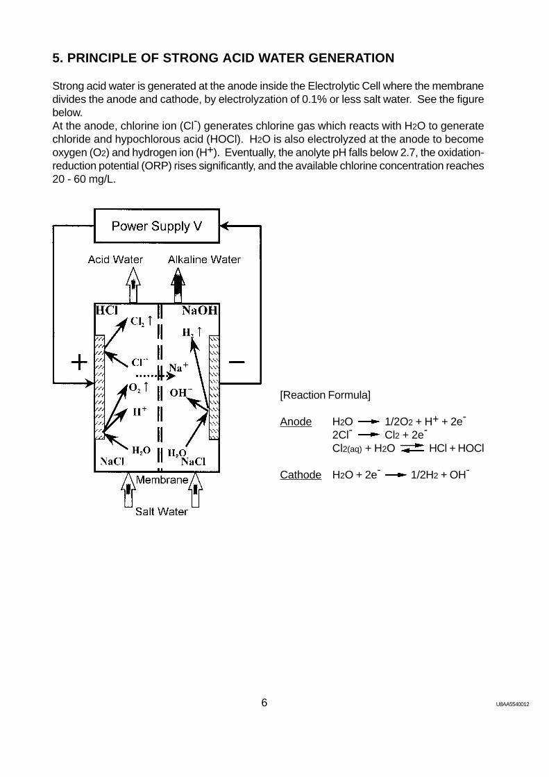
5. PRINCIPLE OF STRONG ACID WATER GENERATION
Strong acid water is generated at the anode inside the Electrolytic Cell where the membranedivides the anode and cathode, by electrolyzation of 0.1% or less salt water. See the figurebelow.At the anode, chlorine ion (Cl-) generates chlorine gas which reacts with H2O to generatechloride and hypochlorous acid (HOCl). H2O is also electrolyzed at the anode to becomeoxygen (O2) and hydrogen ion (H+). Eventually, the anolyte pH falls below 2.7, the oxidation-reduction potential (ORP) rises significantly, and the available chlorine concentration reaches20 - 60 mg/L.
[Reaction Formula]
Anode H2O 1/2O2 + H+ + 2e-
2Cl- Cl2 + 2e-
Cl2(aq) + H2O HCl + HOCl
Cathode H2O + 2e- 1/2H2 + OH-
7 U8AA5540012
II. CONSTRUCTION
1. GENERAL
[1] Display PanelSee “3. DISPLAY PANEL“.
[2] Lamp BoardBoard with lamps indicating unit status.
[3] Control BoxSee “4. CONTROL BOX”.
[4] Flow Switching ValveChanges the flow direction of electrolyzed water.
[5] Microswitch [Direction]Senses the direction of the Flow Switching Valve.
[6] Microswitch [Location]Senses the location of the Flow Switching Valve.
[7] Gear MotorRotates the Impeller inside the Flow Switching Valve.
[8] Water ValveSupplies potable water to the Electrolytic Cell.
[9] Flow Rate SensorSenses potable water flow.
[10] Surge AbsorberInterrupts a temporary voltage surge.
[11] Electrolytic CellElectrolyzes diluted salt water and generates acid and alkaline water.
[12] LegNot adjustable.
[4][6] [5] [3]
[7] [2][1]
[8]
[9] [15]
[10]
[11] [14]
[12] [13]
[17][16] [18]
[19]
[20]
[21]
[27]
[22][26]
[25] [24] [23]
8 U8AA5540012
[13] DoorProvided with Door Lock.
[14] Door LockLocks the Door.
[15] Control PanelSee “2. CONTROL PANEL”.
[16] Acid Water OutletDispenses acid water during the normal operation and alkaline water during the flushingprocess.
[17] Alkaline Water OutletDispenses alkaline water during the normal operation and acid water during the flushingprocess.
[18] Water Supply InletInlet for potable water supplied to the unit.
[19] Electromagnetic Metering PumpSupplies salt water to the unit.
[20] Terminal BlockUsed when the Water Tank (sold separately) is installed.
[21] Rear Panel (not shown)Removed when the Water Tank Float Switches are connected to the Terminal Block orthe Remote Controller is connected to the Control Box.
[22] Blind BushingRemoved when the Water Tank Float Switches are connected to the Terminal Block orthe Remote Controller is connected to the Control Box.
[23] Power Supply CordFlexible cord with a grounding conductor and grounding type attachment plug.
[24] Drain CapUsed for draining the pipes.
[25] Salt Water HoseIncludes the PVC hose and the Water Level Sensor.
[26] Water Level SensorSenses the level of salt water inside the Salt Water Tank.
[27] Salt Water FilterRemoves foreign substances in salt water.
9 U8AA5540012
2. CONTROL PANEL
[1] Display WindowDisplays the operation time, amperage or voltage during the normal operation anderror codes in case of trouble.
[2] Operation Time LampDisplay Window displays operation time (h) when this lamp is on.
[3] Amperage LampDisplay Window displays amperage (A) when this lamp is on.
[4] Voltage LampDisplay Window displays voltage (V) when this lamp is on.
[5] Display Select ButtonSwitches the display of the Display Window.
[6] Flush ButtonFunctions as a switch to flush the pipes beyond the acid and alkaline water outlets.
[7] Set ButtonOnly qualified service personnel or installer may press this button to adjust various setvalues.
[8] Amperage Control VolumeOnly qualified service personnel may turn this control to change the set amperage.
[9] Voltage Control VolumeOnly qualified service personnel may turn this control to change the set voltage.
[10] Power SwitchTurns the unit on and off.
[1]
[10]
[2]
[3]
[4]
[5][9]
[6]
[7] [8]
10 U8AA5540012
[1] Dispense ButtonStarts and stops dispensing electrolyzed water.
[2] Dispensing Lamp (Green)Indicates that the unit is producing water.
[3] Ready Lamp (Green)Flashes until the desired settings are achieved and stays on when the unit is dispensingelectrolyzed water.
[4] Add Salt Water Lamp (Red)Indicates that the Salt Water Tank level is too low.
[5] Flush Lamp (Red)Stays on during the flush operation. Indicates that the unit is in flush cycle.
[6] Electrolytic Cell Replace Lamp (Red)Indicates that the cell life is near completion. Flashes continuously from 2900 hours to3000 hours and stays on after 3000 hours.
[7] Service Call Lamp (Red)Indicates that there is trouble detected.
[7] [6] [5] [4] [3] [2] [1]
3. DISPLAY PANEL
11 U8AA5540012
4. CONTROL BOX
[1] Switching RegulatorSupplies power to start the Programmable Controller, etc.
[2] Noise BoardBoard to remove noise in the unit.
[3] Current SensorReads amperage in the Electrolytic Cell.
[4] Water Level Sensor BoardBoard to control the Water Level Sensor.
[5] Operation BoardBoard with switches to operate the Control Panel, etc.
[6] Magnetic ContactorSwitches polarity of the Electrolytic Cell.
[7] Relay 1For [10] DC Power Supply.
[8] Relay 2Controls the water level in the Water Tank.
[9] Relay 3Switches the electrolyzed water display of the Remote Controller.
[10] DC Power SupplyPower supply for cells to generate electrolyzed water.
[11] Programmable ControllerManages all controls of the unit.
[12] Noise FilterRemoves noise from 1. [19] Electromagnetic Metering Pump.
[13] Ferrite Core (not shown)Removes noise in the unit.
[1][2]
[3]
[4][13]
[5]
[12]
[6] [11]
[10]
[9][8]
[7]
12 U8AA5540012
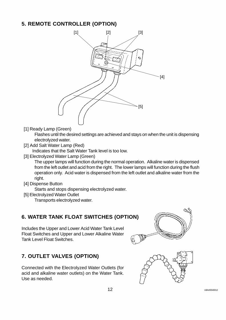
5. REMOTE CONTROLLER (OPTION)
[1] Ready Lamp (Green)Flashes until the desired settings are achieved and stays on when the unit is dispensingelectrolyzed water.
[2] Add Salt Water Lamp (Red)Indicates that the Salt Water Tank level is too low.
[3] Electrolyzed Water Lamp (Green)The upper lamps will function during the normal operation. Alkaline water is dispensedfrom the left outlet and acid from the right. The lower lamps will function during the flushoperation only. Acid water is dispensed from the left outlet and alkaline water from theright.
[4] Dispense ButtonStarts and stops dispensing electrolyzed water.
[5] Electrolyzed Water OutletTransports electrolyzed water.
6. WATER TANK FLOAT SWITCHES (OPTION)
Includes the Upper and Lower Acid Water Tank LevelFloat Switches and Upper and Lower Alkaline WaterTank Level Float Switches.
7. OUTLET VALVES (OPTION)
Connected with the Electrolyzed Water Outlets (foracid and alkaline water outlets) on the Water Tank.Use as needed.
The water electrolyzer is provided with the nine set items of the following functions:
No.
A1
A2
A3
A4
A5
A6
A7
A8
A9
Set Items
Cell Lifecycle (h)3000 - 8000
Amperage (A)0.0 - 18.0
Voltage (V)0.0 - 18.0
Cell Reverse Time (h)0 - 150
AmperageAccumulation Time (s)1 - 90
Storage Mode/Hand-washing Mode
Cell Running/Reverse Time Reset
Initial Flush Cycle (s)0 - 120
Automatic DispensingControl 10 s - 4 m
Functions
Adjustment is required if the electrode lifecycle gets longer(Initial: 3000 h).
Changes the pH value (Initial: 14.0 A).To increase the pH value, raise the amperage.
Changes the available chlorine concentration (Initial: 10.0 V).To reduce the residual chlorine concentration, raise the voltage.
Adjustment is required if the electrode lifecycle gets longer(Initial: 12 h, 0 means no reversal).
Changes the reaction to the varying amount of additionalconcentrated salt water (Initial: 3 s). To delay the amperagefeedback reaction, extend the time setting.
Chooses between hand-washing mode using the optionalremote controller and storage mode to store water in the tank(Initial: hand-washing mode).
Resets the built-in timer for replacing the Electrolytic Cell.
Changes the time to supply water for flushing away non-electrolyzed water in the Electrolytic Cell in the initial operation(Initial: 3 s).
Adjusts the dispensing time for automatic dispensing control(Initial: continuous).Continuous: Continuously dispenses until the Dispensing
Button is pushed for the second time.Automatic: Automatically stops when the adjusted time has
passed since the Dispensing Button is pushed.
IMPORTANT
1. The set items A1, A4, A5, A8 and A9 should not be changed unless directed byan engineer.
2. The set item A7 should be used only when the Electrolytic Cell is replaced.
Note: 1. The set amperage and voltage can be changed just by turning each control volume.For more accurate adjustment, however, always use the A2 and A3 adjust modes
14 U8AA5540012
and turn the volume while watching the Display Window on the Control Panel.
2. Do not change the amperage and voltage extremely from the initial set values. Theunit may shut down by the error code E42 or E43.
ADJUSTMENT PROCEDURE
Adjust the above set items while electrolyzed water is being dispensed, the Add Salt WaterLamp is on, or the Service Call Lamp is on.
A1: Cell Lifecycle
1) Run the electrolyzer to dispense electrolyzed water or to turn on the Add Salt Water Lampor the Service Call Lamp.
2) Open the Door.3) The Display Window on the Control Panel shows the present cell lifecycle, amperage (A)
or voltage (V), or an error code. Keep on pushing the Set Button.4) Check that the Display Window reads “Nor.”, which means the unit is in the normal mode.
5) Keep on pushing the Set Button, and press the Display Button one time.6) Check that the Display Window reads “AdJ.”, which means the unit is in the adjust mode.
Lighting
Lighting
Lighting
Flashing
15 U8AA5540012
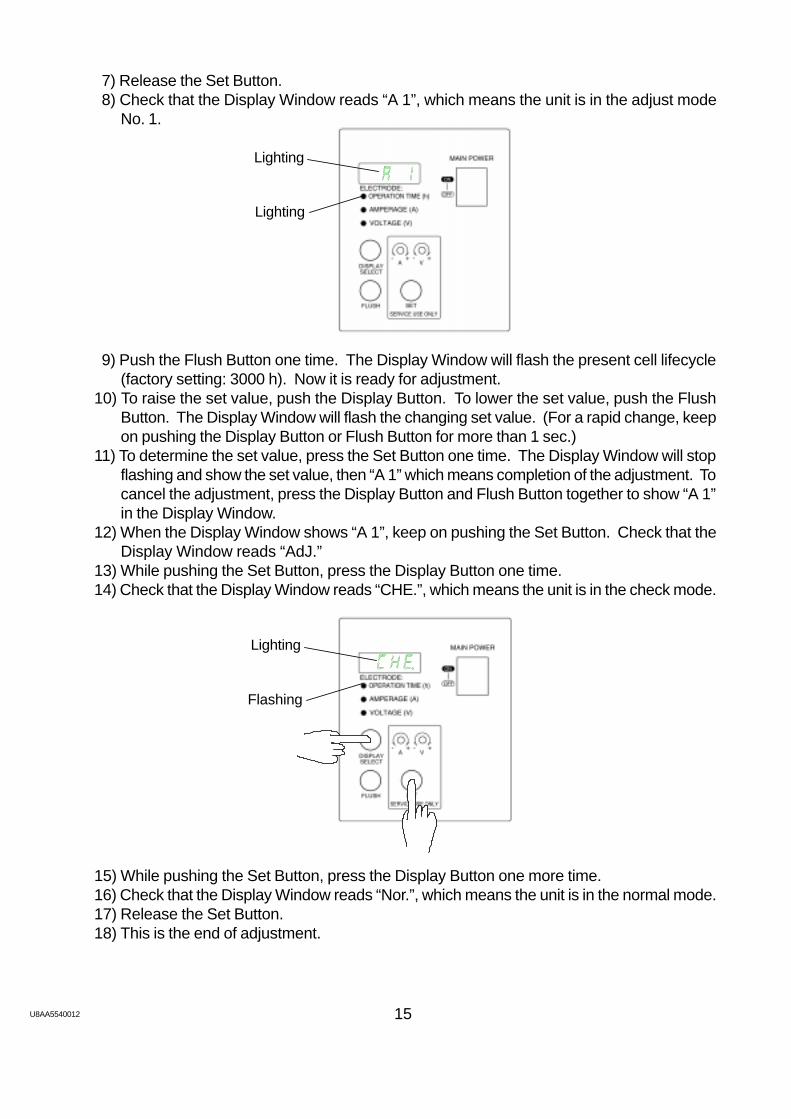
7) Release the Set Button.8) Check that the Display Window reads “A 1”, which means the unit is in the adjust mode
No. 1.
9) Push the Flush Button one time. The Display Window will flash the present cell lifecycle(factory setting: 3000 h). Now it is ready for adjustment.
10) To raise the set value, push the Display Button. To lower the set value, push the FlushButton. The Display Window will flash the changing set value. (For a rapid change, keepon pushing the Display Button or Flush Button for more than 1 sec.)
11) To determine the set value, press the Set Button one time. The Display Window will stopflashing and show the set value, then “A 1” which means completion of the adjustment. Tocancel the adjustment, press the Display Button and Flush Button together to show “A 1”in the Display Window.
12) When the Display Window shows “A 1”, keep on pushing the Set Button. Check that theDisplay Window reads “AdJ.”
13) While pushing the Set Button, press the Display Button one time.14) Check that the Display Window reads “CHE.”, which means the unit is in the check mode.
15) While pushing the Set Button, press the Display Button one more time.16) Check that the Display Window reads “Nor.”, which means the unit is in the normal mode.17) Release the Set Button.18) This is the end of adjustment.
Lighting
Lighting
Lighting
Flashing
16 U8AA5540012
A2: Amperage
1) Follow the steps 1) to 8) in “A1: Cell Lifecycle” to show “A 1” in the Display Window on theControl Panel.
2) Push the Set Button one time to show “A 2” in the Display Window.3) Push the Flush Button one time. The Display Window will flash the present amperage
(factory setting: 14.0 A). Now it is ready for adjustment.
4) Use a precision screwdriver to turn the Amperage Control Volume. The Display Windowwill flash the changing set value.
5) When the Display Window shows the desired set value, push the Set Button one time.The Display Window will stop flashing and show the set value, then “A 2” which meanscompletion of the adjustment.
6) When the Display Window shows “A 2”, keep on pushing the Set Button. Check that theDisplay Window reads “AdJ.”
7) While pushing the Set Button, press the Display Button one time.8) Check that the Display Window reads “CHE.”, which means the unit is in the check mode.9) While pushing the Set Button, press the Display Button one more time.
10) Check that the Display Window reads “Nor.”, which means the unit is in the normal mode.11) Release the Set Button.12) This is the end of adjustment.
A3: Voltage
1) Follow the steps 1) to 8) in “A1: Cell Lifecycle” to show “A 1” in the Display Window on theControl Panel.
2) Push the Set Button two times to show “A 3” in the Display Window.3) Push the Flush Button one time. The Display Window will flash the present voltage (factory
setting: 10.0 V). Now it is ready for adjustment.4) Use a precision screwdriver to turn the Voltage Control Volume. The Display Window will
flash the changing set value.5) When the Display Window shows the desired set value, push the Set Button one time.
The Display Window will stop flashing and show the set value, then “A 3” which meanscompletion of the adjustment.
6) When the Display Window shows “A 3”, keep on pushing the Set Button. Check that theDisplay Window reads “AdJ.”
Flashing
Flashing
17 U8AA5540012
7) While pushing the Set Button, press the Display Button one time.8) Check that the Display Window reads “CHE.”, which means the unit is in the check mode.9) While pushing the Set Button, press the Display Button one more time.
10) Check that the Display Window reads “Nor.”, which means the unit is in the normal mode.11) Release the Set Button.12) This is the end of adjustment.
A4: Cell Reverse Time
1) Follow the steps 1) to 8) in “A1: Cell Lifecycle” to show “A 1” in the Display Window on theControl Panel.
2) Push the Set Button three times to show “A 4” in the Display Window.3) Push the Flush Button one time. The Display Window will flash the present cell reverse
time (factory setting: 12 h). Now it is ready for adjustment.4) To raise the set value, push the Display Button. To lower the set value, push the Flush
Button. The Display Window will flash the changing set value. (For a rapid change, keepon pushing the Display Button or Flush Button for more than 1 sec.)
5) To determine the set value, press the Set Button one time. The Display Window will stopflashing and show the set value, then “A 4” which means completion of the adjustment. Tocancel the adjustment, press the Display Button and Flush Button together to show “A 4”in the Display Window.
6) When the Display Window shows “A 4”, keep on pushing the Set Button. Check that theDisplay Window reads “AdJ.”
7) While pushing the Set Button, press the Display Button one time.8) Check that the Display Window reads “CHE.”, which means the unit is in the check mode.9) While pushing the Set Button, press the Display Button one more time.
10) Check that the Display Window reads “Nor.”, which means the unit is in the normal mode.11) Release the Set Button.12) This is the end of adjustment.
A5: Amperage Accumulation Time
1) Follow the steps 1) to 8) in “A1: Cell Lifecycle” to show “A 1” in the Display Window on theControl Panel.
2) Push the Set Button four times to show “A 5” in the Display Window.3) Push the Flush Button one time. The Display Window will flash the present amperage
accumulation time (factory setting: 3 s). Now it is ready for adjustment.4) To raise the set value, push the Display Button. To lower the set value, push the Flush
Button. The Display Window will flash the changing set value. (For a rapid change, keepon pushing the Display Button or Flush Button for more than 1 sec.)
5) To determine the set value, press the Set Button one time. The Display Window will stopflashing and show the set value, then “A 5” which means completion of the adjustment. Tocancel the adjustment, press the Display Button and Flush Button together to show “A 5”in the Display Window.
6) When the Display Window shows “A 5”, keep on pushing the Set Button. Check that theDisplay Window reads “AdJ.”
18 U8AA5540012
7) While pushing the Set Button, press the Display Button one time.8) Check that the Display Window reads “CHE.”, which means the unit is in the check mode.9) While pushing the Set Button, press the Display Button one more time.
10) Check that the Display Window reads “Nor.”, which means the unit is in the normal mode.11) Release the Set Button.12) This is the end of adjustment.
A6: Storage Mode/Hand-washing Mode
1) Follow the steps 1) to 8) in “A1: Cell Lifecycle” to show “A 1” in the Display Window on theControl Panel.
2) Push the Set Button five times to show “A 6” in the Display Window.3) Push the Flush Button one time. The Display Window will flash the following patterns:
HANd ---------With the Remote Controller installedPOOL --------With the Water Tank installedSFt.H ---------Do not set.SFt.P ---------Do not set.
4) Push the Display Button or Flush Button. The Display Window will flash the other setmode.
5) To determine the set mode, press the Set Button one time. The Display Window will stopflashing and show the set mode, then “A 6” which means completion of the adjustment.
Flashing Flashing
Flashing Flashing
19 U8AA5540012
To cancel the adjustment, press the Display Button and Flush Button together to show “A6” in the Display Window.
6) When the Display Window shows “A 6”, keep on pushing the Set Button. Check that theDisplay Window reads “AdJ.”
7) While pushing the Set Button, press the Display Button one time.8) Check that the Display Window reads “CHE.”, which means the unit is in the check mode.9) While pushing the Set Button, press the Display Button one more time.
10) Check that the Display Window reads “Nor.”, which means the unit is in the normal mode.11) Release the Set Button.12) This is the end of adjustment.
A7: Cell Running/Reverse Time Reset
1) Follow the steps 1) to 8) in “A1: Cell Lifecycle” to show “A 1” in the Display Window on theControl Panel.
2) Push the Set Button six times to show “A 7” in the Display Window.3) Push the Flush Button one time. The Display Window will flash “ ≡ ≡ ≡ ≡”. Now it is ready
to reset the cell running/reverse time.4) To reset, press the Set Button for 10 sec. The Display Window will stop flashing “ ≡ ≡ ≡ ≡”
and show “Good”, then “A 7” which means completion of the resetting. To cancel theresetting, press the Display Button and Flush Button together to show “A 7” in the DisplayWindow.
5) When the Display Window shows “A 7”, keep on pushing the Set Button. Check that theDisplay Window reads “AdJ.”
6) While pushing the Set Button, press the Display Button one time.7) Check that the Display Window reads “CHE.”, which means the unit is in the check mode.8) While pushing the Set Button, press the Display Button one more time.9) Check that the Display Window reads “Nor.”, which means the unit is in the normal mode.
10) Release the Set Button.11) This is the end of resetting.
A8: Initial Flush Cycle Time
1) Follow the steps 1) to 8) in “A1: Cell Lifecycle” to show “A 1” in the Display Window on theControl Panel.
2) Push the Set Button seven times to show “A 8” in the Display Window.3) Push the Flush Button one time. The Display Window will flash the present initial flash
cycle (factory setting: 3 s). Now it is ready for adjustment.4) To raise the set value, push the Display Button. To lower the set value, push the Flush
Button. The Display Window will flash the changing set value. (For a rapid change, keepon pushing the Display Button or Flush Button for more than 1 sec.)
5) To determine the set value, press the Set Button one time. The Display Window will stopflashing and show the set value, then “A 8” which means completion of the adjustment. Tocancel the adjustment, press the Display Button and Flush Button together to show “A 8”in the Display Window.
20 U8AA5540012
6) When the Display Window shows “A 8”, keep on pushing the Set Button. Check that theDisplay Window reads “AdJ.”
7) While pushing the Set Button, press the Display Button one time.8) Check that the Display Window reads “CHE.”, which means the unit is in the check mode.9) While pushing the Set Button, press the Display Button one more time.
10) Check that the Display Window reads “Nor.”, which means the unit is in the normal mode.11) Release the Set Button.12) This is the end of adjustment.
A9: Automatic Dispensing Control
1) Follow the steps 1) to 8) in “A1: Cell Lifecycle” to show “A 1” in the Display Window on theControl Panel.
2) Push the Set Button eight times to show “A 9” in the Display Window.3) Push the Flush Button one time. The Display Window will flash the present automatic
dispensing control (factory setting: continuous “CoNt.”). Now it is ready for adjustment.4) To raise the set value, push the Display Button. To lower the set value, push the Flush
Button. The Display Window will flash the changing set value. (For a rapid change, keepon pushing the Display Button or Flush Button for more than 1 sec.)
5) To determine the set value, press the Set Button one time. The Display Window will stopflashing and show the set value, then “A 9” which means completion of the adjustment. Tocancel the adjustment, press the Display Button and Flush Button together to show “A 9”in the Display Window.
6) When the Display Window shows “A 9”, keep on pushing the Set Button. Check that theDisplay Window reads “AdJ.”
7) While pushing the Set Button, press the Display Button one time.8) Check that the Display Window reads “CHE.”, which means the unit is in the check mode.9) While pushing the Set Button, press the Display Button one more time.
10) Check that the Display Window reads “Nor.”, which means the unit is in the normal mode.11) Release the Set Button.12) This is the end of adjustment.
Note: If the automatic dispensing control setting is short, the unit may stop automatically inthe middle of the next adjustment. In this case, adjust the setting as follows:1) Turn on the Power Switch. While the Display Window shows nothing, push the Flush
Button for more than 10 sec.2) Select the desired mode, and adjust the setting.
21 U8AA5540012
2. FUNCTIONS AND ADJUSTMENT OF CHECK ITEMS
The water electrolyzer is provided with the ten check items of the following functions:
No.
C1
C2
C3
C4
C5
C6
C7
C8
C9
C10
Check Items
Output Conditions
Input Conditions
Present Average Amperage (A)
Present Stroke Speed (spm)
Present Cell Reverse Time (h)
Last Error Code
Last Error Cell Running Time (h)
Last Error Cell Reverse Time (m)
Last Error Average Amperage (A)
Last Error Stroke Speed (spm)
Functions
Displays all the present output conditions in theDisplay Window on the Control Panel.
Displays all the present input conditions in theDisplay Window on the Control Panel.
Displays the average amperage at present.
Displays the stroke speed at present.
Displays the cell reverse time at present.
Displays the error code of the last error.
Displays the cell running time of the last error.
Displays the cell reverse time of the last error.
Displays the average amperage of the last error.
Displays the stroke speed of the last error.
CHECKING PROCEDURE
1) Run the electrolyzer to dispense electrolyzed water or to turn on the Add Salt Water Lampor the Service Call Lamp.
2) Open the Door.3) The Display Window on the Control Panel shows the present cell lifecycle, amperage (A)
or voltage (V), or an error code. Keep on pushing the Set Button.4) Check that the Display Window reads “Nor.”, which means the unit is in the normal mode.
Lighting
Lighting
22 U8AA5540012
5) Keep on pushing the Set Button, and press the Display Button one time.6) Check that the Display Window reads “AdJ.”, which means the unit is in the adjust mode.
Lighting
Flashing
Lighting
Flashing
7) Keep on pushing the Set Button, and press the Display Button one more time.8) Check that the Display Window reads “CHE.”, which means the device is in the check
mode.
9) Release the Set Button.10) Check that the Display Window reads “C 1”, which means the device is in the check
mode No. 1.
Lighting
Lighting
11) Push the Display Button. The Display Window will change from “C 1” to “C 2”. Anotherpush will change “C 2” to “C 3”.
23 U8AA5540012
Relay X3 Magnet Switch
Relay X1
Gear Motor
Water Valve
NonePulse signal toMetering Pump
Output to DC powersupply CNT-TOG
12) When the desired check item code is displayed, push the Flush Button one time. TheDisplay Window will show the present check item information.
13) To finish checking, press the Display Button and Flush Button together to show “C 1”, “C2”... in the Display Window.
14) When the Display Window shows one of those check item codes, keep on pushing theSet Button. Check that the Display Window reads “CHE.”
15) While pushing the Set Button, press the Display Button one time.16) Check that the Display Window reads “Nor.”, which means the device is in the normal
mode.17) Release the Set Button.18) This is the end of checking.
C1: Output Conditions
The lighting LED shows the applicable output is ON.
C2: Input Conditions
The lighting LED shows the applicable input is ON.
Direction Microswitch Location Microswitch
Display Button
Flow Rate Switch
Level SensorFlush Button
Set Button
Max. Water Level(Float Switch ON)
None
24 U8AA5540012
3. OPERATION FLOW CHART
Operation
Press Display Button.
Keep on pushing Set Button, and press Display Button.
Press Flush Button.
Press Set Button. For A7, keep on pushing it for 10 sec.
Press Display Button and Flush Button together.
Normal Mode (Nor.)
Adjust Mode (AdJ.) Check Mode (CHE.)
Set
[1] Cell Running Time (h)
[2] Amperage (A)
[3] Voltage (V)
A1 Cell Lifecycle (h)
A2 Set Amperage (A)
A3 Set Voltage (V)
A4 Cell Reverse Time (h)
A5 Amperage AccumulationTime (h)
A6 Storage Mode/Hand-washing Mode
A7 Cell Running/ReverseTime Reset
A8 Initial Flush Cycle (s)
A9 Automatic DispensingControl
CheckC1 OutputConditions
C2 Input Conditions
C3 Present Average Amperage (A)
C4 Present Stroke Speed (spm)
C5 Present Cell Reverse Time (h)
C6 Last Error Code
C7 Last Error Cell Running Time (h)
C8 Last Error Cell Reverse Time (m)
C9 Last Error Average Amperage (A)
C10 Last Error Stroke Speed (spm)
ditto
ditto
ditto
ditto
ditto
ditto
ditto
ditto
ditto
ditto
ditto
ditto
ditto
ditto
ditto
ditto
ditto
2
1
3
4
5
1 1
1
2 2
2
3 3
4 5
25 U8AA5540012
IV. TECHNICAL INFORMATION
1. WATER CIRCUITPressureGauge Filter
WaterSupply
Pressure ReducingValve (Accessory)
Water Electrolyzer(ROX-20TA-U)
Pressure ReducingValve (2.5kgf/cm2)
WaterSoftener
Control Box
Water Valve
Flow RateSensor
MeteringPump
SaltWater
ElectrolyticCell
Remote Controlleror Tank
2. WIRING DIAGRAM
26 U8AA5540012
27 U8AA5540012
3. PERFORMANCE DATA
The following graph shows the electrode performance curve. The electrode life cycle dependson the free chlorine concentration as well as the raw water quality. To optimize the electrolyzedwater, we recommend the Electrolytic Cell should be replaced every 3,000 hours of operation.
Water Temperature: 25°C* The above data depends on the water temperature and water quality.
Water Temperature: 25°C* The above data depends on the water temperature and water quality.
pH and Amperage
Amperage and Available Chlorine Concentration
29 U8AA5540012
V. SERVICE INFORMATION
1. MAINTENANCE/INSPECTION
Check the following items during maintenance or inspection in normal condition. If any ofthem is found abnormal or defective, repair, replace or adjust it properly.
No.
1
2
3
4
5
6
7
8
9
10
11
12
13
14
15
16
17
18
Inspection
Item
Acid Water pH
Alkaline Water pH
Available ChlorineConcentration (Acid)
Flow Rate (Acid/Alkaline)
Ambient Temp.
Water Supply Temp.
Water Supply Pressure
Cell Replace Lamp
Salt Water Tank
Filter
Water Circuit
Attachment Plug
Exterior
Float Switch
Water Softener
Cartridge Filter
Remote Controller
Labels
Check
Within specified range?
Within specified range?
Within specified range?
Within specified range?
Within specified range?
Within specified range?
Within specified range?
Flashing or lighting?
No dirt buildup?No salt deposit at bottom?
Not clogged with dirt?
No water leak?
Securely plugged in?Not hot?
Clean?
Free of scale?Working properly?
Water softened?Working properly?Set to regenerate water whileunit is out of service?Proper amount of salt inside?
Pressure difference withinspecified range?
Water outlet not blocked?Working properly?
Attached firmly in place?
Remedy
Check by pH tester.
Check by pH tester.
Check by accessory chlorine testpaper or thiosulfuric acid titration.
Check by beaker.
Check by thermometer.
Check by thermometer.
Check by water pressure gauge.
Visually check.
Visually check.Visually check.
Visually check.
Visually check.
Visually check.Check.
Visually check.
Visually check.Check for proper operation.
Check water sample.Check.Check.
Check.
Visually check.
Visually check.Check for proper operation.
Visually check.
30 U8AA5540012
[a] Acid Water pH, Alkaline Water pH [No. 1, 2]
Always use the accessory pH test paper or a pH tester on the market to check pH.Carefully read the instructions provided with the test paper or tester, and use it properly.
[b] Available Chlorine Concentration (Acid) [No. 3]
Always use the accessory test paper or the thiosulfuric acid titration specified below to checkavailable chlorine concentration.Carefully read the instructions provided with the test paper, and use it properly.If the available chlorine concentration is below the specified level (it also depends on theoriginal water quality), be sure to adjust the amperage and voltage to make the concentrationreach the specified level.
Thiosulfuric Acid Titration
< Instruments >Erlenmeyer flask (100mL - 200mL)Measuring cylinder (50mL)Measuring pipet or syringe (graduated by 0.1 or 0.5mL)Reagents: Potassium iodide (KI)
Sodium thiosulfate (1/100N)
1) Wash the Erlenmeyer flask, measuring cylinder and measuring pipet with tap water.2) Take 35.4mL of acid water in the cylinder, and pour it gently into the flask.3) Put some potassium iodide (two or three grains) into the flask, and stir it lightly. The acid
water will turn orange.4) Take some sodium thiosulfate (1/100N) with the pipet, and read it.5) Drop the sodium thiosulfate (1/100N) little by little into the flask while stirring it lightly. When
the acid water starts losing its color, drop the reagent with special care.6) When the acid water turns from orange into clear, stop dropping the reagent and read the
pipet.7) The dropping amount (mL) x 10 will be the available chlorine concentration (mg/L). For
example, if the dropping amount is 4.5mL, the available chlorine concentration will be45mg/L.
[c] Cell Replace Lamp [No. 8]
The flashing Cell Replace Lamp indicates that the Electrolytic Cell has run for 2900 - 3000hours and should be replaced soon.The lighting Cell Replace Lamp indicates that the Electrolytic Cell has run for 3000 hours ormore and needs immediate replacement.
[d] Water Softener [No. 15]
Carefully read the instructions provided with the water softener, and use it properly.Check that the water softener is set to start regeneration while electrolyzed water is notdispensed (ex. 2:00AM).
31 U8AA5540012
The water softener also needs salt for regeneration. Always add a proper amount of salt intothe water softener. Give the user sufficient instructions to add salt periodically.
[e] Cartridge Filter [No. 16]
Replace the cartridge filter when the pressure gauge readings on the primary side of thewater softener and on the secondary side of the cartridge filter differ by 0.1MPa (1.0kgf/cm2)or more.
2. SERVICE DIAGNOSIS
When the unit shuts down with the Service Call Lamp lighting:
Lamp
ServiceCall
ServiceCall
Code
E11
E14
E42
Problem
After water valveopens, flow ratesensor does notdetect water flowfor 3 sec.
After water valvecloses, flow ratesensor detectswater flow for 3sec.
Metering pumpstroke speedexceeds 360spmfor 60 sec.
Check
Water Supply
Water Outlet
Connecting Hose
Alkaline Water Line
Flow Switching Valve
Water Valve
Flow Rate Sensor
ProgrammableController
Water Valve
Flow Rate Sensor
Salt Water Tank
Set Voltage
Set Amperage
Possible Cause
Cut off.
Blocked.
Crushed or bent.
Scaled up.
Clogged.
Clogged.
Connector in badcontact.
Defective.
Clogged.
Connector in badcontact.
Defective.
Water valve outputcontact defective.
Flow rate sensorinput defective.
Clogged.
Defective.
Salt water too thin.
Too low.
Too high.
Remedy
Recover.
Unblock.
Release stress.
Clean.
Unclog.
Unclog.
Improve contact.
Repair or replace.
Unclog.
Improve contact.
Repair or replace.
Repair or replace.
Repair or replace.
Unclog.
Repair or replace.
Thicken.
Raise.
Reduce.
32 U8AA5540012
Lamp
ServiceCall
ServiceCall
Code
E42
E43
E51
E52
Problem
Metering pumpstroke speedexceeds 360spmfor 60 sec.
Metering pumpstroke speeddoes not exceed10spm for 60sec.
Stroke speedexceeds laststroke speed +10spm for 20sec.
Abnormal inputfrom currentsensor
Check
Filter
Salt Water Hose
Water Supply
Cell SaltConcentration
Set Voltage
Set Amperage
Salt Water Tank
Metering Pump HeadDial
Salt Water Hose
Filter
Salt Water Tank
Switching PowerSupply
Control PanelBackside Board
Relay
Magnetic Contactor
Current Sensor
Switching PowerSupply
Possible Cause
Dirty.
Clogged.
Air inside.
Too much.
Too high.
Too high.
Too low.
Salt water too thick.
Not positioned at“E”.
Air inside.
Clogged.
Dirty.
Salt water too thin.
Defective.
DC power supplyline opened.
Connector in badcontact.
Parts on boarddefective.
Bad contact.
Bad contact.
Defective.
Connector in badcontact or opencircuit.
Defective.
Connector in badcontact.
Remedy
Clean.
Unclog.
Remove air.
Keep within specifiedrange.
Repeat dispensing tosupply water andlower concentration.
Reduce.
Raise.
Thin.
Turn into “E” position.
Remove air.
Unclog.
Clean.
Thicken.
Repair or replace.
Repair.
Improve contact.
Repair or replace.
Repair or replace.
Repair or replace.
Repair or replace.
Improve contact orrepair.
Repair or replace.
Improve contact.
33 U8AA5540012
Lamp
ServiceCall
Code
E61
E62
E65
Problem
Flow switchingvalve directionmicroswitch turnsON and OFF 5times in 2 min.
Programmablecontroller outputsto flow switchingvalve gear motorfor 20 sec.
After gear motorstops, locationmicroswitch turnsON.
Check
Gear Motor
Location Microswitch
Microswitch
Gear Motor
Possible Cause
Will not stop.
Fails to detect.
Fails to detect.
Overrun.
Remedy
Repair or replace.
Repair or replace.
Repair or replace.
Repair or replace.
* When restarting the electrolyzer after a shutdown for some error, check the amperage andvoltage on the electrolytic cell with an ammeter and voltmeter (not those provided on theelectrolyzer). If the voltage reading is normal but the amperage is still low, the salt waterinlet can be clogged or the salt water may be too thin. If both amperage and voltage are toolow, check for abnormal DC power supply or a bad contact of the relay or magnetic contactor.
* The electrolyzer may also shut down for some error when the flow rate varies for acid waterand alkaline water because of different piping resistance (ex. connecting hose crushed orone of the water outlets under water). Even if the electrolyzer is in operation, varying flowrate may cause low pH and chlorine concentration. Keep a constant flow rate by balancingthe piping resistance.
* The amperage varies with the salt water concentration and metering pump stroke speed.When restarting the electrolyzer after a shutdown for some error, check the change inamperage and the metering pump operation.
HOSHIZAKI ELECTRIC CO., LTD.3-16 MINAMIYAKATA, SAKAE, TOYOAKE,AICHI 470-1194 JAPANPHONE: 0562-97-2111