HOST Programming Environment Options GMAS .NET API GMAS Windows Library PLC Open IEC 61131-3 programing GMAS .NET API libraries using Standardized PLC Open motion and administrative functionality to program your application on Microsoft Visual Studio IDE Environment. GMAS Win32 libraries for RPC (Remote Process Control) using C/C++ Microsoft visual Studio environment programing, based on standard PLC Open motion and administrative functions. Built-in EAS IDE for IEC6113-1 Standardized PLC Open Programming that supports all 5 languages: SFC, FBD, LD, ST, IL. GMAS Developer Studio C/C++ IDE Drive .NET API Drive User program IDE GMAS Developer Studio (Eclipse Based) IDE for Native C/C++ Programming languages , based on standard PLC Open motion and administrative functions. .NET API for Drive level functions such as Download FW, Send/Get drive Commands, Error Handling etc. for direct communication between the Host computer and the drive. Built-in EAS IDE with up to 48Kbyte for local drive level user programing. Modbus TCP protocol Ethernet IP protocol GMAS Script Manager Standardized Modbus- UDP protocol for communication with Host Computers, HMI and PLC... Standardized Ethernet-IP protocol for communication with Host Computers, HMI, and PLC... Built-in In EAS (Elmo Application Studio) GSM tool for writing fast machine motion sequences.
Transcript
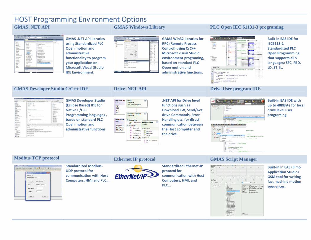
HOST Programming Environment OptionsGMAS .NET API GMAS Windows Library PLC Open IEC 61131-3 programing
GMAS .NET API libraries using Standardized PLC Open motion and administrative functionality to program your application on Microsoft Visual Studio IDE Environment.
GMAS Win32 libraries for RPC (Remote Process Control) using C/C++ Microsoft visual Studio environment programing, based on standard PLC Open motion and administrative functions.
Built-in EAS IDE for IEC6113-1 Standardized PLC Open Programming that supports all 5 languages: SFC, FBD, LD, ST, IL.
GMAS Developer Studio C/C++ IDE Drive .NET API Drive User program IDE
GMAS Developer Studio (Eclipse Based) IDE for Native C/C++ Programming languages , based on standard PLC Open motion and administrative functions.
.NET API for Drive level functions such as Download FW, Send/Get drive Commands, Error Handling etc. for direct communication between the Host computer and the drive.
Built-in EAS IDE with up to 48Kbyte for local drive level user programing.
Modbus TCP protocol Ethernet IP protocol GMAS Script Manager
Standardized Modbus-UDP protocol for communication with Host Computers, HMI and PLC...
Standardized Ethernet-IP protocol for communication with Host Computers, HMI, and PLC...
Built-in In EAS (Elmo Application Studio) GSM tool for writing fast machine motion sequences.
Network Group Axis Motion
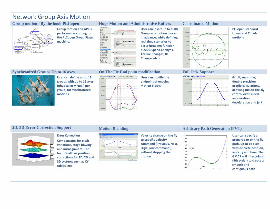
Group motion - By the book PLCopen Huge Motion and Administrative Buffers Coordinated Motion
Group motion and API is performed according to the PLCopen Group State machine.
User can insert up to 1000 Group axis motion blocks in advance, while defining real time scenarios to occur between function blocks (Speed Changes, Torque Changes, IO Changes etc.)
PLCopen standard Linear and Circular motions
Synchronized Groups Up to 16 axes On The Fly End point modification Full Jerk Support
User can define up to 16 groups with up to 16 axes (physical or virtual) per group, for synchronized motions.
User can modify the endpoint of ongoing motion blocks
64 bit, real-time, double precision profile calculations, allowing full on-the-fly control over speed, acceleration, deceleration and jerk
2D, 3D Error Correction Support Motion Blending Arbitrary Path Generation (PVT)
Error Correction
Compensates for pitch variations, stage bowing and misalignment. The feature allows position corrections for 1D, 2D and 3D systems such as XY tables, etc.
Velocity change on the fly to specific velocity command (Previous, Next, High, Low command ) without stopping the motion
User can specify a prepared or on the fly path, up to 16 axes - with discrete position, velocity and time. The GMAS will interpolate (5th order) to create a smooth and contiguous path
Network Group Axis Motion
PLCopen Coordinate Systems Network Group Limits (Safe Zones) Support Spline Support
GMAS supports the following PLCopen coordinate systems:
ACS – Axis-related coordinate system
MCS – Machine-related coordinate system
Safe Zones can be set to avoid entering prohibited areas.
User can define either to work in Fixed time or Constant Velocity spline modes.
“On the fly” position and velocity offset setting Kinematics Powerful wire and die bonding solutions
Link/Unlink a virtual profile to your real motion profile “On the Fly” during motion trajectory running time.
GMAS can execute complex defined real time Kinematic Transformations for machine related coordinated systems.
Extremely fast and smooth operation in position, velocity, acceleration and deceleration using special transitions between segmented motion function blocks.
Transition Curves
Arc segments that are inserted automatically by the GMAS pre-profiler module to guarantee that every two consecutive motions are contentiously and smoothly mandated. GMAS supports
3rd, 5th and 6th polynomial order calculations to promise smooth continuity in velocity and accelerations.
Corner Distance
Corner Distance
Polynom 3
Corner Distance
Polynom 5
Network Single Axis Motion
Axis motion - By the book PLCopen Huge Motion and Administrative Buffers Simple Point to Point motion
Single axis motion and API is performed according to the PLCopen Single Axis State machine.
User can insert up to 1000 Single axis motion blocks in advance, while defining real time scenarios to occur between function blocks (Speed Changes, Torque Changes, IO Changes etc.).
User can perform any motion. From simple point to point motions to complex synchronized motions
Using the Drive Profiler - Distributed Motion On The Fly End point modification Full Jerk Support
User can choose to use the drives profiler while the GMAS only controls the beginning and end of motion commands.
User can modify the endpoint of ongoing motion blocks
64 bit, real-time, double precision profile calculations, allowing full on-the-fly control over speed, acceleration, deceleration and jerk
User can choose to use the motion profiles generated by the GMAS. The GMAS will download the target point every defined cycle time.
Velocity change on the fly to specific velocity command (Previous, Next, High, Low command ) without stopping the motion
User can specify a prepared or on the fly path with discrete position, velocity and time. The GMAS will interpolate (5th order) to create a smooth and contiguous path
Network Single Axis Motion
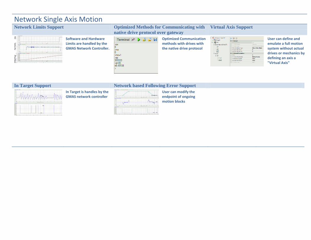
Network Limits Support Optimized Methods for Communicating with
native drive protocol over gateway
Virtual Axis Support
Software and Hardware Limits are handled by the GMAS Network Controller.
Optimized Communication methods with drives with the native drive protocol
User can define and emulate a full motion system without actual drives or mechanics by defining an axis a "Virtual Axis"
In Target Support Network based Following Error Support
In Target is handles by the GMAS network controller
User can modify the endpoint of ongoing motion blocks
Communication To Devices
Number of Axes DS401 - IO Devices Protocol Support Ether CAT Protocols
GMAS supports up to 100 devices on CAN or Ether CAT fieldbuses
Standard CAN Open DS 401 IO Protocols supported.
CoE - CAN Over Ethercat. Standard DS402 over the Ethercat Network
EoE - Ethernet Over Ethercat. Ability to communicate with drives with native drive language.
FoE - Ability to download firmware to FULL Ethercat network simultaneously.
Standard CANopen DS402 -Drive Motion Protocol Support DS406 -CAN Encoder
Whether the device is a motion device, Encoder, or IO - The GMAS can be configured to communicate with the selected device
Protocol to drives is strict DS402 supporting the following protocols:
Cyclic Position
Cyclic Velocity
Cyclic Torque
Interpolated Position
Profile Position
Profile Velocity
Profile Torque
Homing
Ability to configure and read position of CanOpen Encoders on the CAN Network
3rd
Party EtherCAT IO modules support Virtual CAN Encoder
Support 3rd
party EtherCAT IO modules for controlling and monitoring analog and digital IO’s.
GMAS can simulate a CAN encoder on the network, thus saving on expensive CAN device.
Scaling factors using DS 402 UU (User Units) for position, Velocity and acceleration scaling.
Position/Velocity & Torque Offset support.
Velocity offset (DS402 object 0x60B1) mapping for smooth velocity and acceleration profiles
32 bit modulo with special RADO (Rotary Axis Direction Option)
• Normal positioning
• Negative movement
• Positive movement
• Positioning with shortest way
Dynamic Braking Sine Sweep Emulation Reference commands
Logical Braking for reduced braking time.
Simple BW test by the user using EAS sine sweep interface.
Wide range of profiler reference commands
• CanOpen/Ether- CAT DS402 based standard
• Analog (+-10V) • P&D • User Program
MASTER SLAVE
Special Functionality
MIMO Based Gantry solution Gantry Absolute and differential 1D error
correction
OC function in Gantry system
Gold Drives’ powerful control enables true synchronization between 2 gold drive without the need to designate, and thus waste, an entire motion controller exclusively on Gantry Realization.
Differential and Absolute 1 Dimension error correction implementation on the drive level.
In both Master and slave axes the error correction mechanism is active.
Output compare functionality for triggering external equipment as a function of the Master axis position is supported in Gantry system
Gantry Home Offset Measurement Feedback Emulation in Gantry system ECAM and Gearing
Special procedure for measuring the offset between two indexes located on separate linear scales of a Gantry system.
Both Master and Slave motors are powered on and operating in Gantry mode during the whole measurement time.
Quadrature/Analog/ absolute feedback emulation in a standalone or network based Gantry system
Standardized PLC Open ECAM and Gearing functionality.
Linear and cyclical ECAM with fixed or different segment gaps.
Output Compare – 1
OC[1-12]
Output Compare – 2
OC[21-32]
Output-1
Output-2
Output-3
Output-4
Output-14
Output-15
Output-16
Sensor Position
Sensor Position
Pulses
Pulses
OP/OB[i] Commands
Special Functions
(Brake, MO, AOK)Level
Level
Function Change
User Command
Out # Defined
-------- ------------------------------------
15,16,3,14 General Purpose Outputs
2 Special Function
1 Output Compare 1
4 Output Compare 2
Indexes Offset
RLS FLS
RLS FLS
Index
Mark1
Index
Mark2
Index
Mark3
50mm
Index
Mark N-1Index
Mark N
50mm
Gantry
Master
Gantry
Slave
Servo capabilities
PIP cascaded Vector control 1:2:2 servo control topology High order filters
Advanced and extremely fast vector control
Current Control Loop sampling time down to 40 us (25 kHz)
Velocity Loop sampling time down to 80 us (12.5 kHz)
Position Loop sampling time down to 80 us (12.5 kHz)
Low Pass, High Pass , Notch ,Anti-Notch , Lead lag and 2nd order general filters for overcoming “defects” of the mechanical system
Advanced Tuning Commutation options System analysis
Fast, easy and efficient advanced Automatic Tuning tool.
Choose your most application suitable commutation method:
• Stepper • Digital halls • Analog halls • Binary search • Auto phasing
System analysis in the time domain (Step Response) and frequency domain (
Nichols, Bode)
Plant Identification methods Controller Design methods Current Gain Scheduling
Multiple plant, fast identification or Sine sweep Identification
Automatic Controller design methods or Manual design for the advanced control engineer
Current gain scheduling to compensate for the motor's non-linear characteristics and for bus voltage variations
4
Servo capabilities
Friction Compensation Field weakening (Phase advance) 2000:1 Current dynamic range
• Using nonlinear compensation method to overcome friction by adding an offset command to the integral filter of the velocity loop
• velocity GS table
Enhanced torque-speed operation using advanced field weakening.
Highest current (Torque/ Force) dynamic range of >2000
3 step Gain scheduling 1 Dimension Error correction Velocity and position Gain scheduling
Using 3 controller gain sets before, during and after motion.
Error Mapping for high system accuracy.
Velocity and Position gain scheduling for ultimate servo loop performance.
Any Servo Motor Control Stepper motor control Planar stage control
• Brush and Brushless • AC Servo • Rotary & Linear • Torques (DDR) • Voice Coil (DC)
High speed 2 Phase, 3 Phases open and close loop stepper motor control.
MIMO (Multi Input Multi Output) control solution structure for Planar X/Y systems.
Torque-Speed Curve with Field Weakening (Phase Advance)
0
1
2
3
4
5
6
0 0.5 1 1.5 2 2.5 3 3.5 4 4.5 5
Speed, KRPM
To
rq
ue
, N
m w/o Phase Advance
w/ Phase Advance -
continuous
w/ Phase Advance - peak
Servo capabilities
I2t Protection Current Limits “R” Type current limits
Keeping constant Thermal Stress (I
2t) for all peak
currents and thus avoiding the amplifier from “over stressing” and keeping it within the safety limits.
In Elmo Amplifiers & Drives:
• IP = 2X IC
Peak Duration for rated IP ≈ Typical 3 seconds
stead of having “fuse” I2t limits to the IP, the
R type has not IP capabilities, but only continuous current capabilities that is higher than the “traditional” IC (by 1.5)
and is only thermally limited.
Power Switching- FASST Power Switching- FASST- Low EMI
The FASST Technology is realized in the FID, Elmo’s fully customized analog/digital IC designed to “Optimum Drive” of power MosFETs and IGBTs
Provides fast and highly efficient switching
Keeps process “soft” with no stress on power device with very low EMI
Low EMI below the conductive medical standard.
Advanced Feedback Technology
Simplicity in Feedback Configuration Dual loop options Analog Encoder Sin/Cos, Port B
Elmo’s “Socket Technology” embedded in Gold Drives and supported by the EAS, enables the quick and simple set-up of any type or configuration of encoders.
Gold Servo Drives support Port A and Port B manipulations. This also applies to Dual Loop applications, dual sensor motors, etc.
Using internal Programmable multipliers: x4 to x8192 to achieve high analog encoder resolutions.
Absolute position sensors Up to 32 bit absolute resolution Absolute encoder masking
Gold Drive Absolute Position Sensors support:
• Serial Absolute - EnDat 2.1/2.2
• Serial Absolute – BiSS • Serial Absolute – Panasonic • Serial Absolute – Tamagawa • Serial Absolute – Mitutoyo • Serial Absolute – SSI • Virtual Absolute – Gurley
Gold absolute encoders can reach up to 32 bits per revolution, up to 2.5 MHz clock frequencies and automatic propagation delay compensation.
For operating higher-resolution absolute encoders, the user can mask both upper and lower bits via the EAS without any performance degradation.
Emulation , Port C FIR and Glitch Filters
Feedback Emulation (socket) into one of the following signals format:
• A & B quadrature • Pulse & direction • Up & down • Hall signals
For “smoother” operation and improved noise immunity, the FIR (Finite Impulse Response) filter and “Glitch” filters can be used.
Advanced Feedback Technology
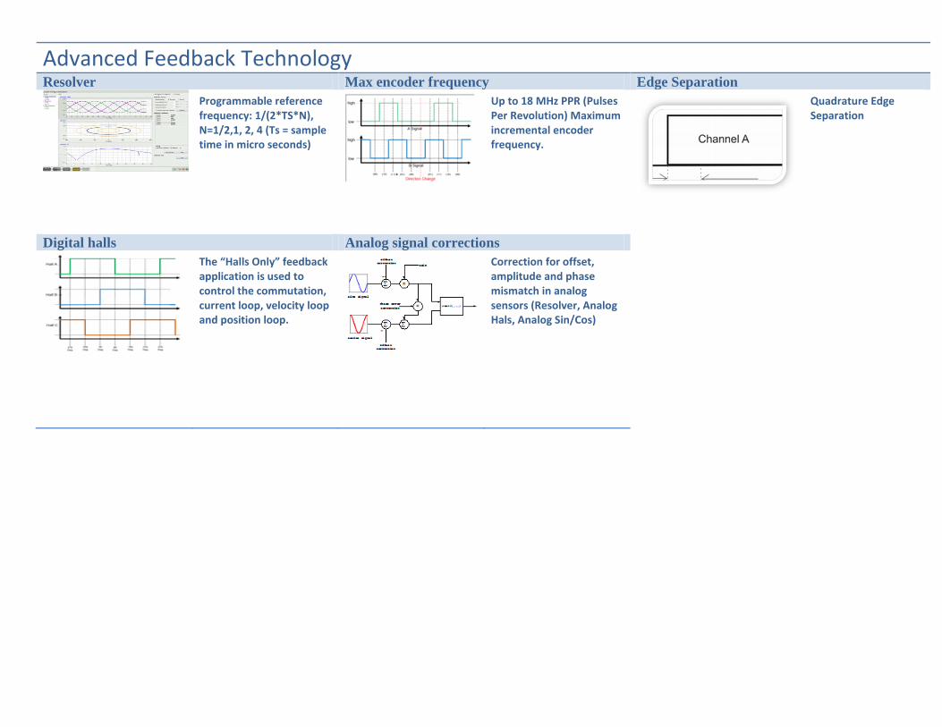
Resolver Max encoder frequency Edge Separation
Programmable reference frequency: 1/(2*TS*N), N=1/2,1, 2, 4 (Ts = sample time in micro seconds)
Up to 18 MHz PPR (Pulses Per Revolution) Maximum incremental encoder frequency.
Quadrature Edge Separation
Digital halls Analog signal corrections
The “Halls Only” feedback application is used to control the commutation, current loop, velocity loop and position loop.
Correction for offset, amplitude and phase mismatch in analog sensors (Resolver, Analog Hals, Analog Sin/Cos)
Hardware solutions Gold product family Servo Drives Drive Motor solutions SimplIQ product family servo drives
Sophisticated Motion Control Solutions for Modern Industrial Automation.
DC Input: 7.5 to 750 VDC - for DC brush, sinusoidal and trapezoidal motors
“All in One” solutions of motor Drive and feedback combined in one package.
Elmo Motion Control's SimplIQ product family is a set of sophisticated AC and DC input voltage based, network-based motion control products for brush, brushless and linear motors
Power supplies ExtrIQ Line Servo Control Products Network Motion Controller
Compact, cost effective, direct-to-mains power supplies, designed for multiple servo drives solutions.
Digital Servo Drives, and Analog Servo Amplifiers suit military and Extreme Environmental Conditions
Elmo’s Gold Maestro leads the market when it comes to advanced, fast, precise, easy-to-use, and cost-effective distributed networking motion controllers.
Military Motion Controller One Solution, Any Application
Elmo's Military Motion Controller, the Puma, has a compact rugged, MIL-style casing, that contains an advanced, easy-to-use, and cost-effective multi-axis Network Motion Controller and 2 extremely powerful Gold Hornet servo drives of up to 20 A/100V (3.3 Kw ) each
The Elmo Application Studio (EAS) – a multi-functional and friendly design environment
The Gold Maestro - a true network-based, machine motion controller that can handle up to 100 axes
High-performance, advanced and intelligent Servo Drives