Hot-Die Forging of P/M Ni-Base Superalloys C.P. Blankenship, Jr., M.F. Henry, J.M. Hyzak”f, R.B. Rohling and E.L. Hall GE Corporate Research and Development PO BOX 8, Schenectady, NY 12301 tWyman Gordon Company PO BOX 8001, N. Grafton, MA 01536 Abstract Hot die forging was evaluated as a process for producing acceptable grain structures in P/M nickel base superalloy RenC 88DT. Laboratory and subscale experiments were carried out, and grain sizes in the range IO-20pm were produced after supersolvus heat treatment. There were some issues with die fill and cracking. Further process improvements would be required for successful implementation. Introduction Advanced gas turbine rotor components made from powder metallurgy (P/M) Ni-base superalloys are currently isothermally forged at slow strain rates and high temperatures (slightly below the v solvus) [ 1,2]. These processing parameters are chosen mainly to encourage superplastic deformation, resulting in low forging loads and low die stresses. This operation requires expensive tooling, an inert environment, and slow ram speeds for successful operation. Superplastic deformation in the workpiece also allows large geometric strains to be achieved during the forging operation without cracking. At the end of the forging operation, no substantial increase in dislocation density should be observed, as strain is accommodated by grain boundary sliding and diffusional processes. In the event that dislocations are generated, the high temperatures and slow stroke rates allow dynamic recovery to occur. The grain size after forging is typically 3-5pm. After forging and heat treatment, cooling and aging operations are performed. For applications that demand enhanced creep and time dependent fatigue crack propagation resistance, a coarse grain size (20-40pm) is required. This is achieved by heat treating above the y solvus. Complex contoured forgings contain a range of strain and strain rates. If temperatures are too Ed,ted by R. D Kmnger, 0. ,. Deye, 0. L. Anton, A. D C&l, M. V. Nathal, T. M. Pollock, and 0. A. Woodford The Mmerals, Metals & Materials Society, 1996 low, or local strain rates are too high, diffusional processes cannot keep up with the imposed strain rate. In this case, dislocations are generated. If a component is subsequently heat treated above the y solvus, this may lead to an occurrence referred to as critical grain growth (CGG), which leads to a bimodal grain size distribution [3]. Factors in addition to dislocation density, such as carbon/boron/ nitrogen content and subsolvus annealing time also appear to influence the grain size distribution [3]. Numerous studies have illustrated the effect of retained strain’ on final grain size [3-61. Data from room temperature compression tests contained in Figure 1 summarize this trend for the powder metallurgy nickel base superalloy RenC 88DT. 10000 I I I I I q ALA 1000 e Backgroun 2 2100 N q --D---n 3 .9 10 e-e-e-e I Supersolvus Heat Treated 0.1 I I I I I 0 10 20 30 40 50 Strain (%) Figure 1. Grain size2 after supersolvus heat treatment as a function of room temperature compression lFor convenience, the term “retained strain” is used to describe the dislocation density, or metallurgical strain present in the microstructure. 2ALA indicates the largest grain diameter in the section, while background grain size represents the average grain size.
Transcript
Hot-Die Forging of P/M Ni-Base Superalloys
C.P. Blankenship, Jr., M.F. Henry, J.M. Hyzak”f, R.B. Rohling and E.L. Hall
GE Corporate Research and Development PO BOX 8, Schenectady, NY 12301
tWyman Gordon Company PO BOX 8001, N. Grafton, MA 01536
Abstract
Hot die forging was evaluated as a process for producing acceptable grain structures in P/M nickel base superalloy RenC 88DT. Laboratory and subscale experiments were carried out, and grain sizes in the range IO-20pm were produced after supersolvus heat treatment. There were some issues with die fill and cracking. Further process improvements would be required for successful implementation.
Introduction
Advanced gas turbine rotor components made from powder metallurgy (P/M) Ni-base superalloys are currently isothermally forged at slow strain rates and high temperatures (slightly below the v solvus) [ 1,2]. These processing parameters are chosen mainly to encourage superplastic deformation, resulting in low forging loads and low die stresses. This operation requires expensive tooling, an inert environment, and slow ram speeds for successful operation. Superplastic deformation in the workpiece also allows large geometric strains to be achieved during the forging operation without cracking. At the end of the forging operation, no substantial increase in dislocation density should be observed, as strain is accommodated by grain boundary sliding and diffusional processes. In the event that dislocations are generated, the high temperatures and slow stroke rates allow dynamic recovery to occur. The grain size after forging is typically 3-5pm. After forging and heat treatment, cooling and aging operations are performed. For applications that demand enhanced creep and time dependent fatigue crack propagation resistance, a coarse grain size (20-40pm) is required. This is achieved by heat treating above the y solvus.
Complex contoured forgings contain a range of strain and strain rates. If temperatures are too
Ed,ted by R. D Kmnger, 0. ,. Deye, 0. L. Anton, A. D C&l, M. V. Nathal, T. M. Pollock, and 0. A. Woodford
The Mmerals, Metals & Materials Society, 1996
low, or local strain rates are too high, diffusional processes cannot keep up with the imposed strain rate. In this case, dislocations are generated. If a component is subsequently heat treated above the y solvus, this may lead to an occurrence referred to as critical grain growth (CGG), which leads to a bimodal grain size distribution [3]. Factors in addition to dislocation density, such as carbon/boron/ nitrogen content and subsolvus annealing time also appear to influence the grain size distribution [3].
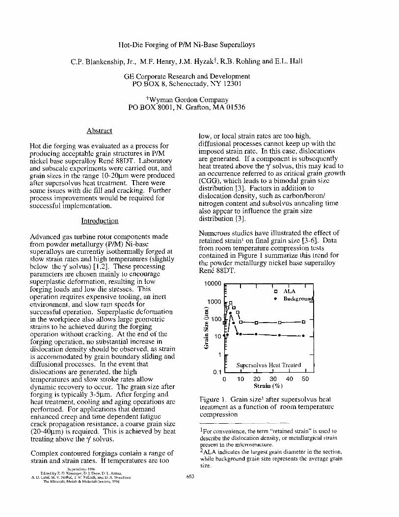
Numerous studies have illustrated the effect of retained strain’ on final grain size [3-61. Data from room temperature compression tests contained in Figure 1 summarize this trend for the powder metallurgy nickel base superalloy RenC 88DT.
10000 I I I I I q ALA
1000 e Backgroun
2
2100 N q --D---n 3 .9 10 e-e-e-e
I
Supersolvus Heat Treated 0.1 I I I I I
0 10 20 30 40 50 Strain (%)
Figure 1. Grain size2 after supersolvus heat treatment as a function of room temperature compression
lFor convenience, the term “retained strain” is used to describe the dislocation density, or metallurgical strain present in the microstructure. 2ALA indicates the largest grain diameter in the section, while background grain size represents the average grain size.
Analogous behavior is observed in RenC 95, cast and wrought superalloys [7-91 and other alloy systems [lo]. This behavior may be translated to elevated temperature deformation; however, strain rate and temperature replace strain as the primary variables that influence the amount of retained strain [ 111. Prior studies [3,12,13] demonstrated that a window exists in strain-rate and temperature space in which critical grain growth can be avoided, thus producing a microstructure of uniform 20-40pm grains after supersolvus heat treatment.
Critical grain growth is thought to result from nucleation limited recrystallization followed by grain growth until the strain free grains impinge on one another. It occurs over a narrow range of retained strain. Slightly higher retained strain results in a higher nucleation density and a finer resultant grain size. Slightly lower retained strain is insufficient to trigger the recrystallization process. Thus the term critical grain growth was adopted to describe the observation that a critical amount of strain was required to lead to this undesirable microstructure.
Critical grain growth is not observed in high volume fraction 1/ alloys until heat treatment is performed above the v solvus. It is therefore noted that, in this complicated alloy system, factors in addition to retained strain influence grain structure evolution. Particles that pin grain boundaries play an active role in controlling grain size, most notably, the coherent, high volume fraction y phase. Carbides, borides and oxides are also reported to influence final grain size, especially if the alloy is heat treated above the y solvus [3].
An alternative procedure to high temperature- low strain rate, isothermal forging is to forge the component fast and cold enough so that the retained strain everywhere in the part is above the amount that would lead to critical grain growth. If successful, this procedure would offer the added benefit of increased productivity and reduced cost for manufacturing turbine disks.
The objectives of this effort were to explore the fundamental metallurgical characteristics of high retained strain forging using laboratory experiments, and investigate the applicability of the process by demonstrating the procedure on a subscale hot die forging press.
Exnerimental Procedure
Rene 88DT extrusions were supplied by Special Metals and Wyman Gordon for this study. The compositions of each extrusion were typical of production Rene 88DT [ 11. Right circular cylinders (RCC’s) (1Omm diameter, 15mm height) and double cone specimens (8.5mm end radii, 25.4mm middle radius, 2 lrnm height) were machined from these extrusions. The extruded microstructure was characterized by recrystallized grains measuring l-5 pm in diameter and 0. l- 1 pm primary v particles. Unrecrystallized powder particles measuring 30- 50 pm in diameter were observed throughout the billet cross section. The apparent area fraction of these unrecrystallized regions varied throughout the cross section, but was on the order of 0.001 to 0.01.
Laboratory forging simulations were performed using a servohydraulic machine equipped with a clamshell furnace. Tests were run at constant true strain rates of 0.1 and 0.01 s-l. After 50% nominal reduction in height, the samples were unloaded, removed from the furnace and air cooled.
Transmission electron microscopy (TEM) was performed on sections of cylinders in the “as- compressed” condition. Slices were made parallel to the forging direction, and mechanically ground to 100Itm in thickness, followed by electropolishing in an 80% methanol 20% perchloric acid solution. The microstructure was characterized using a TEM operated at 300kV.
After a y supersolvus heat treatment of 1150°C for 2 hours, metallographic sections were mechanically polished and etched with Walker’s reagent. Average grain size was measured according to ASTM El 12, except on samples where a bimodal distribution of grain sizes was encountered. In those cases, the abnormally large grains were avoided in measuring an average, or background grain size, and the large grains were measured individually leading to an “as large as” (ALA) grain size using ASTM E930.
Subscale forging trials were performed at Wyman Gordon using a 1500 ton, hot die press. An IN7 18 die set was configured to provide an aggressive shape to test the procedure. Die
654
temperature was not an intentional variable, though it varied slightly from run to run. The nominal die temperature was held near 593°C. The mults were coated with lubricant, and wrapped. The press velocity was 13 mm/s for each test. Mult temperatures were chosen based on laboratory specimen results: 87 1 “C, 927,982, 1037°C. Initial mult geometries are shown in Table I.
Table I. Initial mult geometries for subscale forging experiments
The forged disks were sectioned into quarters. The first quarter was placed in an 1150°C furnace and held for 2 hours. The second quarter was placed in a 1050°C furnace and stabilized for 15 minutes followed by a two hour ramp to 1150°C where it was held for two hours. The third quarter was given a subsolvus anneal of 1050°C for 8 hours followed by a two hour ramp to 1150°C and a 2 hour hold. Gamma prime solvus for RenC 88DT is approximately 1110°C. All sections were air cooled after heat treatment.
Results and Discussion
Laboratory Experiments
As described in the experimental procedure section, laboratory simulations of the forging operation were performed using cylindrical samples. The results of each campaign are summarized below. Table II contains the processing conditions and resulting grain sizes after supersolvus heat treatment.
Table II. Grain size after forging and supersolvus heat treatment (RCC’s)
Forging at low temperatures and high strain rates results in high forging loads and die stresses. Figure 2 compares the true stress-true strain curves for the 87 1°C / 0.1 s-l compression condition to a curve from a compression test run at 1050°C / 0.003 s-1 (nominal isothermal forging conditions that result in superplastic deformation).
Figure 2. Flow stress data comparison: hot die forging results in 10X
higher die stresses.
Figure 3 illustrates the grain structure that is produced after supersolvus heat treatment. Lightly decorated prior powder particle boundaries (MC and Zr02) can be seen, and no primary y is observed.
50 pm Figure 3. Grain structure of cylinder
compressed at 871°C / 0.1 s-l and heat treated at 1150°C for 2 hours.
655
TEM was performed on sections from samples compressed at 87 1°C / 0.1 s-1 and 927°C / 0.01 s-l forging conditions. Figure 4 contains a bright field TEM image of the microstructure after compression at 871°C (no subsequent heat treatment).
4 1:
0.5 p-r-l
Figure 4. TEM image of cylinder compressed at 87 1°C / 0.1 s-1. Microstructure consists mainly of dense dislocation tangles.
Both microstructures contained significant amounts of retained metallurgical strain in the form of dislocation tangles, though the dislocation structures appeared more dense in the 871 “C / 0.1 s-l microstructure.
Production heat treatment cycles typically contain a stabilization at 1050°C on the way to 1150°C. Therefore, TEM samples were prepared from a specimen compressed at 87 1 “C / 0.1 s-l after the stabilization phase of the heat treatment (1050°C for 0.25 hours). Dense dislocation tangles were observed in some areas, while other regions were essentially strain free, as shown in Figure 5. This structure is representative of the recrystallization process. Recovery can be discounted, as it tends to occur continuously throughout the microstructure, rather than as discrete nucleation and growth events. The 1050°C heat treatment followed by a ramp to 1150°C appears to allow the nucleation and (limited) growth of recrystallized grains prior to passing through the y solvus. This sequence is preferred, as the grain structure can undergo its two major alterations one step at a time. Recrystallization and elimination of statistically stored dislocations can occur in the presence of the efficient pinning phase (y). The fine grain microstructure can then undergo a growth spurt after the dissolution of the major pinning phase
without the added complication of another strong driving force (retained strain).
Subscale Forpina Trials
Based on the results of the laboratory compression tests, four forging temperatures and two billet geometries were used to construct an eight run subscale forging matrix (shown in Table III). Conditions were chosen to be representative of hot die forging operations. Billet and die temperatures were significantly lower than those used in isothermal forging operations, and press velocities (strain rates) were significantly higher. These faster and colder process conditions were well outside the superplastic window (as illustrated by the flow stress curves and microstructures in the laboratory experiments). Two concerns in this new processing regime were die strength and cracking of the forged article.
Some of the forgings exhibited cracking in the rim region. In fact, some of the cracks ran a significant distance into the web. Cracking was more severe at the lower forging temperatures, and it was postulated that the low die temperatures contributed to the observed cracking.
Complete metal flow simulations were performed for 927 and 1037°C forging temperatures. Metal flow patterns were similar for the two billet geometries and forging temperatures, but local strain rates, strains and temperatures were quite different. Figure 6 contains calculated final strain contours for the 89mm and 112mm diameter billets forged at 927°C as an example of the modeling results.
Polished and etched cross sections were evaluated for uniformity of grain structure after heat treatment. As mentioned in the experimental procedure section, three heat treatment schedules were applied to sections of each forging:
1. 1150”C/2hours
2. 1050°C / 15 minutes + ramp to 1150°C in 2 hours + 1150°C / 2 hours
3. 1050°C / 8 hours + ramp to 1150°C in 2 hours + 1150°C / 2 hours
656
3m.a
7RwJ
Pm
Iecu
1m
E $ lmo I
sm
Lye
m
Km
lax,
*;,;. I
..i “‘,‘b ;
m**
*c- 1 re . .j
= -r- -Li ia ’ 3,
Figure 5. TEM image of recrystallization process after 15 minutes at 1050°C. The specimen was compressed at 871°C / 0.1 s-l
E” shun mud* 1 A- .wml
EEz 0; 1 ?cm E= ,.xxlD Fc I Kim G. 21732 He 24K”l ,- 27mo Jr 3um ox 28171 ‘3. 37.93
I I I 1 / I I I I cm Llca Ihx) ,sm zm 14c4 2uw 3200 3Mo rmo
Radius
(4
JMO
2m2
z.m
l.doo
ILDO
E .p lam I
Kc
203
~xx)
.coa
.I WC
(b)
I I 1 , I 1 I I I , 4m .m ,200 ,600 2030 2ua 2K.l 3xa 3sC-x
Radius
Figure 6. Effective strain contours (a) 89mm billet and (b) 112mm billet for forging conditions: 927°C and 13 mm/s press velocity.
657
The second procedure is a typical heat treat sequence for production forgings. The third is a procedure that involves an extended subsolvus anneal designed to reduce or eliminate retained strain before ramping to the supersolvus heat treatment temperature. The results of the grain structure evaluations are shown in Table III.
A high, medium, low, zero (H,M,L,O) relative rating scale was used to compare the amounts of cracking and CGG observed. For cracking, the number and depth of cracks determined the rating, and for critical grain growth the approximate area fraction of large grains determined the rating. Figure 7 contains an example of each critical grain growth level.
The grain structure was reasonably uniform in the forgings that did not contain CGG. The average grain size varied between 9 and 18 pm.
The most attractive, uniform grain structure was produced by the heat treatment schedule that included an extended subsolvus anneal. An example is shown in Figure 8.
The results tabulated in Table III were analyzed using statistical data analysis software to evaluate the trends in a quantitative manner. For the relative ratings, values of 0,3,6 and 9 were assigned for ratings of 0, L, M and H respectively. The following variables were evaluated for their effects on cracking, CGG and resultant grain size: forging temperature, billet diameter, and time at 1050°C during heat treatment. The results of the analysis are shown in Table IV. One result that warranted further investigation was that longer times at 1050°C before the supersolvus heat treatment were universally better for producing a uniform grain structure.
Table IV. Correlation of response variables with input conditions (95% confidence)
Ir RESPONSE I INPUT uniformitv of grain structure imnroves with
Ii reduction in forcing temnerature
uniformity of grain structure improves with increase in time at 1050°C amount of cracking decreases with increase in foreinp temnerature
average grain size (pm) decreases with average grain size (urn) decreases with
increase in starting billet diameter reduction in time at 1050°C
A TEM investigation was performed on subscale forgings S/N 7 (89mm diameter billet, 871°C forging temperature) and S/N 5 (89mm diameter billet, 1037°C forging temperature). For each of these forgings, samples were taken from identical locations (between web ring and rim) Foils were examined from the as- compressed and extended subsolvus annealed (1025°C / 8 hours) conditions.
Figure 9 illustrates subtle differences in the as- compressed microstructures for each forging. Significant recrystallization appears to have taken place during forging (dynamic), or during the cool down after forging (meta-dynamic). Some regions remain unrecrystallized, and these regions appear to constitute -10% of the volume in each region that was analyzed. The recrystallized grain size of S/N 7 is -0.5ym, and the recrystallized grain size of S/N 5 is - 1 pm.
The location where the TEM foil was taken was consistent with the large grain band (CGG region) that formed in S/N 5 after direct 1150°C heat treatment. The recrystallized grain size was slightly larger than S/N 7, and the amount of retained strain in the unrecrystallized regions was slightly less than that of S/N 7 (from selected area diffraction patterns and TEM images). MC, boride, and oxide particles were observed in both microstructures, and their distributions were typical of most production RenC 88DT microstructures.
660
Figure 9 (a). Microstructure after forging at 87 1 “C--S/N 7
c. >.w
1 -
+.-’
k\ #d - I
c L -* ” ~~~~~ *a s
**
I i-/T
Figure 9 (b) Microstructure after forging at 1037”C--S/N 5
The subtle differences mentioned could be important, but it is difficult to formulate a consistent rationale that explains why the large grains appear in S/N 5 after direct supersolvus heat treatment, and not in S/N 7.
TEM was performed on these same forgings after extended subsolvus annealing. There was a significant reduction in the amount of strain retained in the microstructures. The grain sizes were measured as 3-Spm. The microstructures were essentially fully recrystallized, and low angle boundaries were observed in both samples.
The TEM results for microstructures given an extended subsolvus anneal indicate that
recrystallization was nearly complete before the ramp to 1150°C was initiated. This heat treatment approach represents a modification to the original stated strategy. It relies on the forging operation to produce enough retained strain to allow complete recrystallization below the y solvus and therefore ensure that the microstructure is strain-free prior to heat treatment above the y solvus.
Summary
The results of the subscale hot die forging experiments summarized in Table III, coupled with the TEM results on laboratory specimens and contoured subscale forgings, indicate that two strategies are available for producing a uniform grain structure.
1. Ensure that there is no retained strain in the microstructure before crossing the v solvus.
2. Ensure that there is sufficient strain to promote a high nucleation density of recrystallization during the supersolvus heat treatment.
Moreover, there are at least two practical production methods for carrying out the first strategy. For example, current isothermal forging practices are aimed at using superplastic deformation to achieve the shape change without causing an increasejn dislocation density. Therefore, subsequent supersolvus heat treatment may be given to a microstructure that is essentially free from retained strain. However, in practice, variability in the process may result in local areas being forged outside the superplastic window, which results in retained strain.
A second approach to the first strategy involves using lower forging temperatures and faster strain rates, typical of hot die forging practices. This practice introduces a high dislocation density into the microstructure of the forged article. The next step is to anneal the forging at a temperature below the v solvus, encouraging complete recrystallization prior to the supersolvus step of the heat treatment.
The second strategy also presents an opportunity to apply the hot die forging technique to produce a uniform grain structure. This process does not appear to be as robust as the extended subsolvus anneal approach. The data generated in this study indicate that the forging
661
temperature must be below 927°C to avoid CGG for a press velocity around 13 mm/s. This temperature range coincides with the temperature which produced significant amounts of cracking. Further process development or canning would be required for successful application of this method.
The grain size typical of isothermal forging and supersolvus heat treatment of RenC 88DT is 20- 40pm. As noted earlier, hot die forging, even with an extended subsolvus anneal, produced a grain size range of lo-20l.tm. The uniform, finer grain, supersolvus heat treated microstructure that is produced by colder, faster forging of Rene 88DT may be useful for a number of applications where strength and LCF performance are key design criteria.
Conclusions
1. Hot die forging in the range of 87 1-927°C produced a uniform grain structure with a standard supersolvus heat treatment. Die fill and cracking posed problems in this temperature range.
2. Hot die forging at higher temperatures produced uniform grain structures when combined with an extended subsolvus anneal (1050°C / 8 hrs) prior to the supersolvus heat treatment. Die fill and cracking tendencies were reduced under these conditions.
Acknowledgments
The authors would like to thank Mark Benz, Joe Corrado, Eric Huron, Richard Menzies and Mike Weimer for technical discussions; Bill Catlin, Jeff Thompson, John Hughes, Don Wemple and Ray Schnoor for experimental assistance; and Yvonne Mastracchio for assistance with the manuscript.
References
1. D.D. Krueger, R.D. Kissinger, R.G. Menzies, C.S. Wukusick, US patent number 4,957,567, General Electric Co.
2. D.D. Krueger, R.D. Kissinger, R.G. Menzies, Super-alloys 1992, S. Antolovich et al., eds. TMS, Warrendale, PA (1992) 277-286.
3. A.E. Murut and C.P. Blankenship, Jr., unpublished research, General Electric Corporate Research and Development, Schenectady, NY, 1993.
4. S. Channon and H. Walker, Trans. Am. Sot. Metals, 45 (1953) 200.
5. J.S. Smart and A.A. Smith in Physical Metallurgy Principles, by R.E. Reed-Hill, PWS (Boston, 1973) 295.
6. C.P. Blankenship, Jr., W.T. Carter, Jr., A.E. Murut and M.F. Henry, Scripta Metall., 31 (1994) 647.
7. M. Koryagina, I. Meshchaninov and S. Khayutin, Fitz Metal. Metalloved., 49, no. 4 (1980) 843.
8. C. White, J. Inst. Metals, 97 (1969) 215.
9. W.H. Couts, in The Superalloys, John Wiley and Sons (1972) 451.
10. P.A. Beck, Phil. Mag., 3 (1954) 245.
11. M.F. Ashby and R.A. Verall, Acta MetaZl., 21(1973) 149.
12. R.D. Kissinger, unpublished research, General Electric Aircraft Engines, Cincinnati, OH, 1991.
13. E.S. Huron and S. Srivatsa, unpublished research, General Electric Aircraft Engines, Cincinnati, OH, 1993.