Hot Electron Behaviors Relevant to Fast Ignit ion K. A. Tanaka 1,2 , H. Habara 1,2 , R. Kodama 1,2 , K. Kondo 1,2 , G.R. Kumar 1,2,3 , A.L. Lei 1,2 , K. Mima 1 , K. Nagai 1 , T. No rimatsu 1 , Y. Sentoku 4 , T. Tanimoto 1,2 , and T. Yabuuchi 1,2 1 Institute of Laser Engineering, Osaka University, 2-6 Yamada-Oka, Suita, Osaka 565-0871 Japan 2 Graduate School of Engineering, Osaka University, 2-1 Yamada-Oka, Suita, Osaka 565-0871 Japan 3 Tata Institute of Fundamental Research, Homi Bahbha Rd., Mumbai 400 004 India 4 Department of Physics, University of Nevada, Reno, Nevada 89521-0042 U.S.A.Hot Fast Ignition Workshop ston Nov. 3, 2006 ILE Osaka University GSE Osaka University
Transcript
Hot Electron Behaviors Relevant to Fast Ignition
K. A. Tanaka1,2, H. Habara1,2, R. Kodama1,2, K. Kondo1,2, G.R. Kumar1,2,
3, A.L. Lei1,2, K. Mima1, K. Nagai1, T. Norimatsu1, Y. Sentoku4, T. Tanimoto1,2, and T. Yabuuchi1,2
1Institute of Laser Engineering, Osaka University,2-6 Yamada-Oka, Suita, Osaka 565-0871 Japan
2Graduate School of Engineering, Osaka University,2-1 Yamada-Oka, Suita, Osaka 565-0871 Japan
3Tata Institute of Fundamental Research,Homi Bahbha Rd., Mumbai 400 004 India
4 Department of Physics, University of Nevada, Reno, Nevada 89521-0042 U.S.A.Hot
9th Fast Ignition WorkshopBoston Nov. 3, 2006
ILEOsaka University
GSEOsaka University
Introduction
Gold cone was used to guide a fast heating laser pulse in order to heat a highly compressed plasma core up to 1 keV.
20-30 % coupling efficiency was indicated in the experiment from the heating laser to the core.
Based on this high efficiency 10 kJ PW laser is now under construction to test even higher fast heating temperature up to several keV in the sub-ignition region.
Is there any way to increase this efficiency?
The experiments were carried out with a Au-cone CD shell. The CD shell was imploded with 9 beam of the GEKKO XIl laser.
Fast ignition experiments of cone-guiding heating of imploded high density core
PW laser for heating1 beam / 300 J1.053 um / 0.5ps~1019 W/cm2
GXII laser for implosion9 beams / 2.5 kJ/0.53 um
1.2ns Flat Top w/ RPP
Au cone 30 o open angle (the picture: 60deg)Thickness of the cone top: 5um
CD shell500umf/6-7umt
R.Kodama et al. Nature 412 798-802 (2001); 418, 933 (2002)
[1]S. Hutchet et al.,
Fast ignition works with gold cone guiding
• The exist of the cone does not reduce the core plasma density much (~80%) [1]
• Laser to core plasma thermal energy coupling conversion efficiency 20%~30%
• Core plasma temperature 1keV at 50-70g/cc due to enforced heating
• Thermal neutron yields increased from 104 to 107
• Cone may focus the heating laser light and hot electrons from the cone wall to the cone inner tip
104
106
108
0.1 1
Th
erm
al
Ne
utr
on
Yie
ld
heating laser power (PW)
2.25
2.45
2.65
Ne
utr
on
Sig
nal
(a.
u.)
Neutron Energy [MeV]
0
1.0
0.5
CE~30%
CE~15%
• Some issues on heating efficiency need to be answered.
- What is the heating laser power at ignition level? PW or higher or lower?
- How the laser-core energy coupling efficiency changes at ignition level? Further increasing or decreasing?
- The reason for CE reduction is attributed to high -e temperature. At ignition level, temperature would be even higher.
Fast ignition with physical cone guiding
0.1
1
Heating laser power (PW)
5~10
?
Th
ermal N
eutro
n Y
ield
?
?
ILEOsaka University
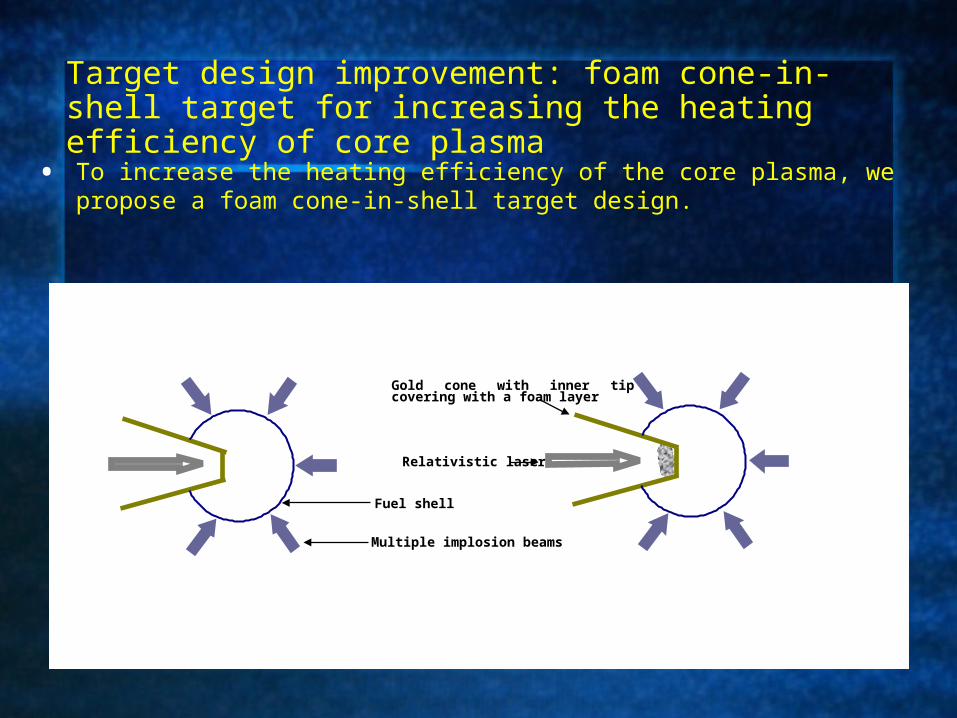
• To increase the heating efficiency of the core plasma, we propose a foam cone-in-shell target design.
Target design improvement: foam cone-in-shell target for increasing the heating efficiency of core plasma
Multiple implosion beams
Relativistic laser
Gold cone with inner tip covering with a foam layer
Fuel shell
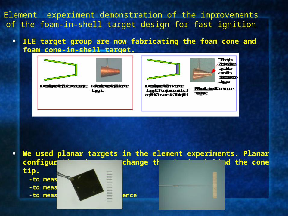
Element experiment demonstration of the improvements of the foam-in-shell target design for fast ignition
• ILE target group are now fabricating the foam cone and foam cone-in-shell target.
• We used planar targets in the element experiments. Planar configuration does not change the physics behind the cone tip.
ratio/f7.6/p-pol/26deg incidence-planar targets: 2um Au+20um Mo, and 2um Au foam+20um Mo-front XPHC: 18um size pinhole/40um Be filter/KeV x-ray range/M=~8.6-back XPHC: 200um size pinhole/40um Be/KeV x-ray range
-ESM: along the laser axis, energy range 1~100MeV.
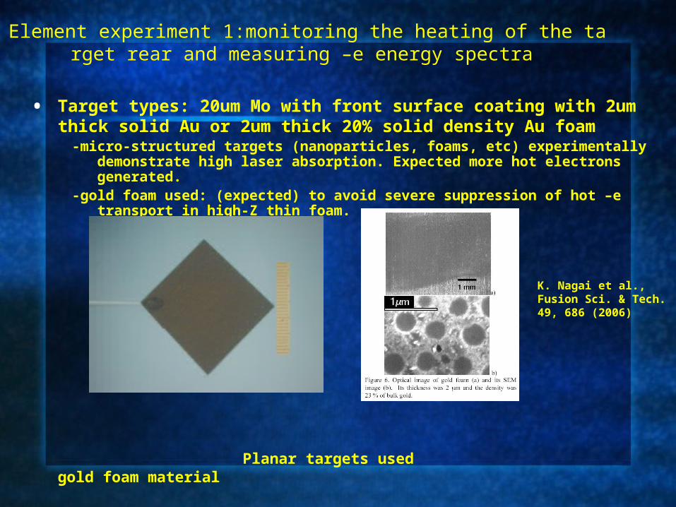
Element experiment 1:monitoring the heating of the target rear and measuring –e energy spectra
• Experimental diagnostics: -XPHCs:
-ESM:
117mm
1010mm
Chamber centerBe 40umt + Pinhole disk
K. A. Tanaka et al., Rev. Sci. Instrum. 76, 013507 (2005)
Provided by ILE measurement group
Au foam coating enhances laser absorption and hot electron generation
F r o n t X P H C B a c k X P H C
G X I I P W l a s e r
T a r g e t
E l e c t r o n s p e c t r o m e t e r
a
c
d
b
0 2 5 0 0 5 0 0 0
e
F r o n t
F r o n t
B a c k
B a c k
F o a m c o a t i n g
S o l i d c o a t i n g
F o a m c o a t i n g
S o l i d c o a t i n g
•Hot -e yield measurement via the back x-ray emission from the target rear due to the heating from hot –e beams
-weak front x-ray emission from the Au foam-coated target. This is due to the low density of the foam.
-stronger back x-ray emission from the Au foam coated target. This is attributed to higher laser absorption and more hot electrons generated with the foam coated target. Back x-ray emission is caused by the hot –e beam heating of the target rear.
-target is thick so that the front x-ray emission may not be responsible for the enhancement of back x-ray emission with foam coated target. Moreover, if it happens, one would expect weak x-ray emission from the foam coated target rear, contrary to the experimental results.
-narrow band-width x-ray image diagnostics needed to give the relative hot –e yield through assuming Plankian emission from the target rear.
-quantitative models and simulations needed
Au foam coating does not change the hot –electron energy spectral characteristics
•Hot -e energy spectra are very similar for solid gold coated and gold foam coated targets, showing a temperature ~1.5 MeV, a typical value for solid aluminum targets
•There is a question: why there is no comparable increase in the amount of hot electrons observed with Au foam coated target?
In vacuum electrons escaping from the target is fully limited by the static potential.
[T. Yabu-uchi et al., submitted to Phys. Rev. E.]
0 3 6 9 12 1510
7
108
109
1010 with foam coating
with solid coating
E
lect
ron
num
ber(
arb.
uni
t)
Electron energy(MeV)
Element experiment 2: measuring –e beam divergence
• Target types: 10um Au foam+10um Au, 12um solid Au
ratio/f3.8/p-pol/21deg incidence-detector stack: placed 40mm away from the target, consisting 12 um Al, 500um
plastic plate, and imaging plate
XPHC
GMII laser
Target
Electron detector stack:IPs
Element experiment 2: measuring –e beam divergence
Electron images
• The Au foam coating does not increase the –e beam divergence.
• There is no filamentary structure observed with the foam coated target.
- 3 6 - 1 8 0 1 8 3 63 . 5
7 . 0
1 0 . 5
1 4 . 0
1 7 . 5
w i t h f o a m c o a t i n gw i t h o u t f o a m c o a t i n g
Ele
ctro
n s
ign
al(
a.u
.)
D e g r e e (0
)
( a ) ( b )
( c )
0 8 . 8 1 7 . 5
w i t h o u t f o a m c o a t i n g w i t h f o a m c o a t i n g
680(FWHM) for foam coated target
720(FWHM) for solid Au target
Electron profilesFitted with Gaussian
dist.
• We propose a foam cone-in-shell target design aiming at improving the cone-in-shell target design to increase the laser energy deposition in the dense core plasma.
• Our element experiment results demonstrated increased laser energy coupling efficiency into hot electrons without increasing the electron temperature and beam divergence with foam coated targets in comparison with solid targets. This may enhance the laser energy deposition in the compressed fuel .