14
Hotliner Application Note 70 Volt Noise Chokes Printed in USA 12/11 Noise Chokes

Hotliner Application Note
70 Volt Noise Chokes
Printed in USA 12/11 Noise Chokes

Table of Contents
Page
1.0 GENERAL 2 2.0 IDENTIFICATION 2
3.0 DESCRIPTION 3
4.0 TYPICAL APPLICATIONS 6
5.0 INSTALLATION 10
6.0 CONNECTIONS 10 7.0 TESTS 11 8.0 TABLES 12
Page 1

1.0 GENERAL
This section provides identification, description, typical applications, installation, test and connection information for 70-volt Noise Chokes manufactured by SNC Manufacturing Co.
1.01 The SNC Noise Choke (See Figure 1) is a bifilar-wound transformer designed to minimize noise and interference currents caused by AC voltages induced on telecommunications circuits from power lines and other sources. It can also be effective in reducing longitudinal impulse noise and radio frequency interference (RFI) on telecommunication facilities.
Figure 1: 70-Volt Noise Choke (P15047) 2.0 IDENTIFICATION Purpose
To reduce noise induced from AC power lines or other sources of interference
To prevent equipment damage or malfunction due to induced AC currents
Application Central Office
Key System Lines PBX Trunks Coin Lines Interoffice Trunks
PBX and Key Systems
Central Office Lines and Trunks Station Loops Off Premise Extension Lines Tie Lines and Trunks Coin Lines DID Trunks Fax Lines
Other
Alarm Circuits Modem Lines POTS Service (depending on distance from central office)
Page 2

Design Features Provides high impedance to longitudinal AC currents Reduces induced voice frequency noise Reduces longitudinal impulse noise Provides minimal insertion loss at voice frequencies No adverse effect on signaling or supervisory signals in most applications Suitable for central office use Suitable for customer premises (the further from the central office, the less chance it will be effective) Copper flux band prevents crosstalk Available in several different mounting configurations
Electrical Characteristics
Refer to Table A for electrical characteristics of SNC Noise Chokes 3.0 Description
3.01 The SNC single-circuit Noise Choke is a bifilar-wound transformer specifically designed to minimize noise and interference currents caused by AC voltages induced on metallic communications cables. Connected in series with the tip (T) and ring (R)* conductors, it presents a high impedance to longitudinal currents. Although inserted in the telephone pair, the Noise Choke (See Figure 2) has a minimal effect on transmission. The negligible amount of additional resistance in the loop does not cause any degradation to signaling or supervision. All SNC Noise Chokes are equipped with a copper flux around the coil winding to prevent crosstalk between adjacent units. When the copper fluxband is grounded, the Noise Choke can effectively suppress RFI and longitudinal impulse noise that may enter the equipment from the facility.
Figure 2: Schematic Of Noise Choke
* In this section, the two conductors of a telecommunications pair will be referred to as the tip(T) and ring (R). In some parts of the world, these same conductors are known as “A” and “B”.
3.02 Four models of the 70-Volt choke are available. These models are listed
In Table B.
3.03 Figure 3 shows a picture of an encapsulated unit (P15043) while Figure 4 shows the unit’s physical dimensions.
Figure 3: (70C) Encapsulated Unit (P15043) Page 3

Figure 4: (P15043) Dimensions
3.04 Figure 5 shows the physical dimensions for the non-encapsulated 70-volt Noise Choke.
Figure 5: Non-encapsulated Choke Dimensions
Assemblies
A. Frame Mounted Units
3.05 For installation on the MDF, SNC Noise Choke units are available in two mounting arrangements: plate mounted (Figure 6) and metal encased (Figure 7). Ordering information for the plate mounted and metal encased units is provided in Tables C and D respectively.
Figure 6: Plate Mounted MDF unit. Figure 7: Dense Pack Page 4

3.06 Frame mounted units are factory wired to a standard wire wrap terminal block equipped with a hinged safety cover. The terminal block is designed to mount on the horizontal side of distributing frames with 8-inch mounting centers. An adapter bracket is provided for use when mounting on older Western Electric or Automatic Electric frames not arranged for 8-inch blocks.
B. Wall or Backboard Mounted Units
3.07 The metal encased Noise Choke (Figure 7) units, which are designed for
frame mounting, are readily adaptable to wall or backboard mounting utilizing the adapter bracket and wood screws.
Note: Metal encased units in a yellow enclosure have a copper fluxband ground lead terminated on the first row (G) of wirewrap terminal. See Figure 8 for terminal configuration. Figure 8: Terminal Block Layout (Top View)
C. Rack Mounted Units
3.08 Available configurations of the rack mounted units are shown in Table E.
D. Special Assemblies
3.09 SNC can also provide special Noise Chokes. For further information on custom arrangements, contact SNC.
Page 5

E. Unequipped Mountings
3.10 For rack mounting of individual Noise Chokes, predrilled, unequipped
mounting plates may be ordered in accordance with Table D. 4.0 TYPICAL APPLICATIONS
4.01 General: When properly employed, Noise Chokes can significantly reduce noise and equipment malfunction problems associated with longitudinal current flow from power line interference. Improper application may negate the benefits or even aggravate the problem. The following paragraphs describe and illustrate several applications of SNC Noise Chokes to reduce power line interference problems.
Note: SNC Noise Chokes are not recommended for use on high-frequency carrier facilities. High signal attenuation at carrier frequencies makes their use impractical.
4.02 Subscriber Loops: To reduce noise on subscriber loops, chokes can be
installed on the central office side of the protectors as shown in Figure 9.
Figure 9: Central Office Application
4.03 PBX Trunks: To reduce noise on PBX trunks, place a Noise Choke at the CO on the equipment side of the projectors as shown in Figure 10.
Figure 10: PBX Trunk Application Page 6
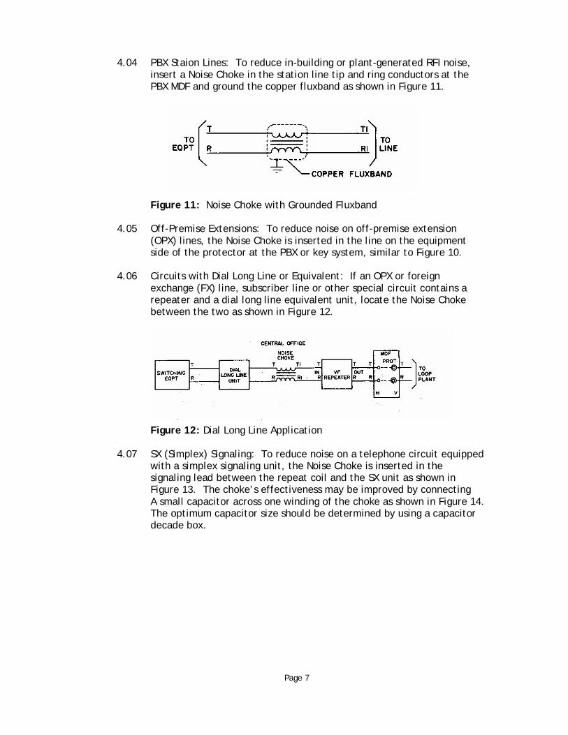
4.04 PBX Staion Lines: To reduce in-building or plant-generated RFI noise, insert a Noise Choke in the station line tip and ring conductors at the PBX MDF and ground the copper fluxband as shown in Figure 11.
Figure 11: Noise Choke with Grounded Fluxband
4.05 Off-Premise Extensions: To reduce noise on off-premise extension (OPX) lines, the Noise Choke is inserted in the line on the equipment side of the protector at the PBX or key system, similar to Figure 10.
4.06 Circuits with Dial Long Line or Equivalent: If an OPX or foreign
exchange (FX) line, subscriber line or other special circuit contains a repeater and a dial long line equivalent unit, locate the Noise Choke between the two as shown in Figure 12.
Figure 12: Dial Long Line Application
4.07 SX (Simplex) Signaling: To reduce noise on a telephone circuit equipped with a simplex signaling unit, the Noise Choke is inserted in the signaling lead between the repeat coil and the SX unit as shown in Figure 13. The choke’s effectiveness may be improved by connecting A small capacitor across one winding of the choke as shown in Figure 14. The optimum capacitor size should be determined by using a capacitor decade box.
Page 7

Figure 13: SX Application
Figure 14: Application of Capacitor to SX Unit
4.08 DX Signaling Circuits: If the telephone circuit is equipped with a
DX (Duplex) signaling unit, the Noise Choke is inserted in the signaling leads between the repeat coil and the DX unit as shown in Figure 15.
Figure 15: DX Application Page 8

4.09 Four-Wire Circuits Extended in Two Wires: For a four-wire circuit with dc signaling simplexed on the transmit and receive pairs, insert a Noise Choke in each of the two simplex legs between the repeat coil and the four-wire termination set as shown in Figure 16. The Noise Choke’s efficiency may be improved by placing a small capacitor across one winding of each choke, as shown in Figure 17. The capacitance value may be determined in accordance with paragraph 4.07.
Figure 16: 4-Wire Term Set Application Page 9

Figure 17: Capacitor Application
5.0 INSTALLATION
A. Basic Individual Chokes
5.01 Backboard Mounting: Mount basic individual Noise Choke units to a wooden backboard as follows:
(a) Using the mounting bracket furnished with each choke, fasten the basic unit to the backboard with two wood screws.
5.02 Mounting Plate Mounting: To mount basic individual Noise Choke units on the predrilled mount plates, proceed as follows:
(a) Fasten the basic Noise Choke to the SNC mounting plate using the 8-32 machine screws, nuts and lockwashers provided.
(b) Discard the mounting brackets of the basic choke. Pass the threaded studs through the holes in the mounting plate and fasten the choke with 8-32 nuts and lockwashers.
6.0 CONNECTIONS
A. General
6.01 Noise Chokes are generally connected in a series between the telecommunication line or certain line-side apparatus and the telecommunications equipment certain equipment-side apparatus. To determine at which point in the circuit to insert the choke, refer to application diagrams of Part 4 of this document.
Page 10
6.02 On SNC Noise Chokes, equipment-side connections are normally made at
terminals T and R, while line-side connections are are made at terminals T1 and R1. Wherever possible, Noise Chokes should be installed on the equipment side of the protectors.
B. Individual Noise Chokes
6.03 Installations comprising basic individual Noise Chokes are wired as follows:
(b) Refer to the schematic shown in Figure 2.
(c) Run a twisted pair from the T and R EQPT terminals of the choke to the LINE terminals of the equipment-side of the apparatus.
(d) Run a twisted pair from the T1 and R1 LINE terminals of the choke to the protectors, telephone line or line-side apparatus.
(e) If RFI suppression is desired, run a wire from the ground tab on the choke to a low impedance ground connection.
6.04 P15043 (70C)
(1) Connect the T (green) ad R (red) EQPT leads to the line terminals of the equipment-side apparatus.
(2) Connect the T1 (green) and R1 (red) leads to the protector, telephone line or line-side apparatus.
(3) If RFI suppression is desired, connect the G (Yellow) wire in either LINE or EQPT to a low impedance ground.
6.05 Dense-Pak (P31046)
(1) Refer to terminal block layout shown in Figure 8.
(2) Cross-connect the T1 and R1 terminals of each choke circuit to the designated protectors or line-side apparatus using twisted pairs.
(3) Cross-connect the T and R terminals of each choke to the designated equipment-side apparatus using twisted pair wire.
(4) To suppress RFI and impulse noise on metal units only, cross- connect terminal G of each choke to the frame ground.
7.0 TESTS
7.01 Upon completion of installation, test the operation of the circuit by placing incoming and outgoing calls and by performing other tests as appropriate to make sure the unit is functioning as expected. Check that the noise requirements are met and that signaling and supervision of the circuit have not been impaired.
Page 11
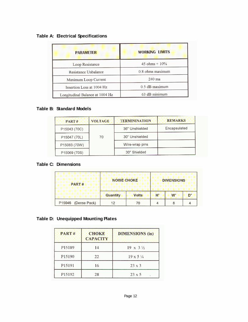
Table A: Electrical Specifications Table B: Standard Models
Table C: Dimensions Table D: Unequipped Mounting Plates Page 12

Table E: Rack Mounted Units
Contact SNC Manufacturing Co. for further information on these quality Noise Solution products:
Induction Neutralizing Transformer (INT) Digital Induction Neutralizing Transformer (DINT) Single Noise Interference Xterminator (SNIX) Noise Chokes Transformer Exciting Network (TEN) Harmonic Drainage Reactor (HDR) Glitch Tamer Telecom Line Conditioner (TLC) Harmonic Suppression Reactor (HSR) HumZapper Li’l Zapper
For further information or for technical support – call 800-558-3325 or visit www.sncmfg.com
SNC Manufacturing Co., Inc.
101 West Waukau Ave., Oshkosh, WI 54902-7299 800-558-3325 or 920-231-7370 - FAX 920-231-1090 E-mail: [email protected] Website: www.sncmfg.com
Page 13 Noise Chokes 12/11


