TM 1 7975-A2-GZ41-00 March 1999 Hotwiret 7975-A1 M/SDSL Standalone Termination Unit Installation Instructions Document Number 7975-A2-GZ41-00 March 1999 Product Documentation on the World Wide Web We provide complete product documentation online. This lets you search the documentation for specific topics and print only what you need, reducing the waste of surplus printing. It also helps us maintain competitive prices for our products. Complete documentation for this product is available at www.paradyne.com. Select Library → Technical Manuals → Hotwire DSL & MVL Systems. Select the following document: 7975-A2-GB20 Hotwire 7975 Standalone Termination Unit User’s Guide To request a paper copy of a Paradyne document: H Within the U.S.A., call 1-800-PARADYNE (1-800-727-2396) H Outside the U.S.A., call 1-727-530-8623 Installation Overview Installation and configuration of the Hotwiret 7975 Standalone Termination Unit consists of: H Connecting power to the unit. H Connecting to the network. H Connecting to a DTE. H Connecting a system terminal. H Providing initial unit identity information or changing existing identity information. H Configuring your unit using internal switchpacks or using the Configuration Edit menus. Before you install the Hotwire 7975 Standalone Termination Unit, read the Important Safety Instructions on page 22. Be sure to register your warranty at www.paradyne.com. Select Service & Support → Warranty Registration.
Transcript
TM
17975-A2-GZ41-00 March 1999
Hotwir e� 7975-A1 M/SDSL Standalone Termination Unit Installation Instructions
Document Number 7975-A2-GZ41-00
March 1999
Product Documentation on the World Wide Web
We provide complete product documentation online. This lets you search thedocumentation for specific topics and print only what you need, reducing thewaste of surplus printing. It also helps us maintain competitive prices for ourproducts.
Complete documentation for this product is available at www.paradyne.com .Select Library → Technical Manuals → Hotwire DSL & MVL Systems.
Select the following document:
7975-A2-GB20Hotwire 7975 Standalone Termination Unit User’s Guide
To request a paper copy of a Paradyne document:
� Within the U.S.A., call 1-800-PARADYNE (1-800-727-2396)
� Outside the U.S.A., call 1-727-530-8623
Installation Overview
Installation and configuration of the Hotwire� 7975 Standalone Termination Unitconsists of:
� Connecting power to the unit.
� Connecting to the network.
� Connecting to a DTE.
� Connecting a system terminal.
� Providing initial unit identity information or changing existing identityinformation.
� Configuring your unit using internal switchpacks or using the ConfigurationEdit menus.
Before you install the Hotwire 7975 Standalone Termination Unit, read theImportant Safety Instructions on page 22.
Be sure to register your warranty at www.paradyne.com . Select Service &Support → Warranty Registration.
2 7975-A2-GZ41-00March 1999
Connecting Power to the Unit
If your package includes a power pack: Plug the power pack into an ac outlethaving a nominal voltage rating between 100–240 Vac. Connect the output cableof the power pack to the connector marked POWER on the rear panel.
If your package includes a direct-connection+24 Vdc power cable: Connect theunit to an external +24 Vdc power source as described in Connecting the Unit toan Optional External +24 Vdc Power Source.
If you will use a –48 Vdc power supply: Connect the unit to an external –48 Vdcpower source as described in the documentation shipped with the power supplyand power cable.
Connecting the Unit to an Optional External +24 Vdc Power Source
Use the following procedures only if you want to use the +24 Vdc powercable.
Using the dc power cable, the Hotwire 7975 Standalone Termination Unit iscapable of operating on a +24 Vdc power supply.
� Procedure
To use the dc power cable:
1. Connect the green wire to a suitable ground.
2. Connect the orange wire to the +24 Vdc source.
3. Connect the white wire to the return.
4. Cut the black, red, and blue wires off at the outer insulation.
5. Plug the power connector into the Termination Unit.
1
2
3
4
5
6
X
X
Ground
RTN
+24 Vdc
X
Black
Red
Green
White
Orange
Blue
99-14158-02
+24 Vdc Power Supply Pinouts
37975-A2-GZ41-00 March 1999
Connecting to the Network
� Procedure
To connect your unit to the network:
1. Connect one end of the supplied network cable into the rear panel DSL jack.Connect the other end to your DSL network interface.
NOTE:Do not use a flat VF network cable as this may severely degrade theperformance of the termination unit. Use only Cat 5 twisted-pair networkcable.
Connecting to the DTE
The Hotwire 7975 Standalone Termination Unit connects to Data TerminalEquipment (DTE) using a 25-pin EIA-530-A interface. Depending on the cableused, the interface can be adapted to an X.21, RS449, or V.35 interface. See theUser’s Guide for more information.
Ferrite Choke
� Procedure
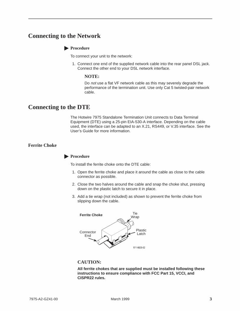
To install the ferrite choke onto the DTE cable:
1. Open the ferrite choke and place it around the cable as close to the cableconnector as possible.
2. Close the two halves around the cable and snap the choke shut, pressingdown on the plastic latch to secure it in place.
3. Add a tie wrap (not included) as shown to prevent the ferrite choke fromslipping down the cable.
97-14820-02
Ferrite Choke
PlasticLatchConnector
End
TieWrap
CAUTION:All ferrite chokes that are supplied must be installed following theseinstructions to ensure compliance with FCC Part 15, VCCI, andCISPR22 rules.
4 7975-A2-GZ41-00March 1999
Connecting to a System Terminal
An optional system maintenance terminal may be attached to your Hotwire 7975 Standalone Termination Unit through the modular jack on the rear panel.The system maintenance terminal allows you to view the status of the unit, andchange configuration options. The terminal must be a VT100-compatible terminalor a PC running terminal emulation software.
� Procedure
To connect your unit to a system terminal:
1. Connect the 9-pin end of the terminal cable into a COM port on your PC.
2. Plug the other end into the modular jack on the rear panel.
3. Set the communication parameters on your PC or terminal to:
— 9600 baud
— 8 bit characters
— no parity
— 1 stop bit
— no flow control
Press Enter from your terminal or PC to activate the Main Menu for the attachedunit. The system runs diagnostics and status checks. After a few moments, theMain Menu or Logon screen appears on your terminal.
Entering Identity Information
After accessing your unit for the first time, use the Change Identity screen todetermine SNMP administrative system information that will be displayed on theIdentity screen of the Status branch. To access the Card Identity screen, followthis menu selection sequence:
Main Menu →Control →Change Identity
57975-A2-GZ41-00 March 1999
Network Configuration
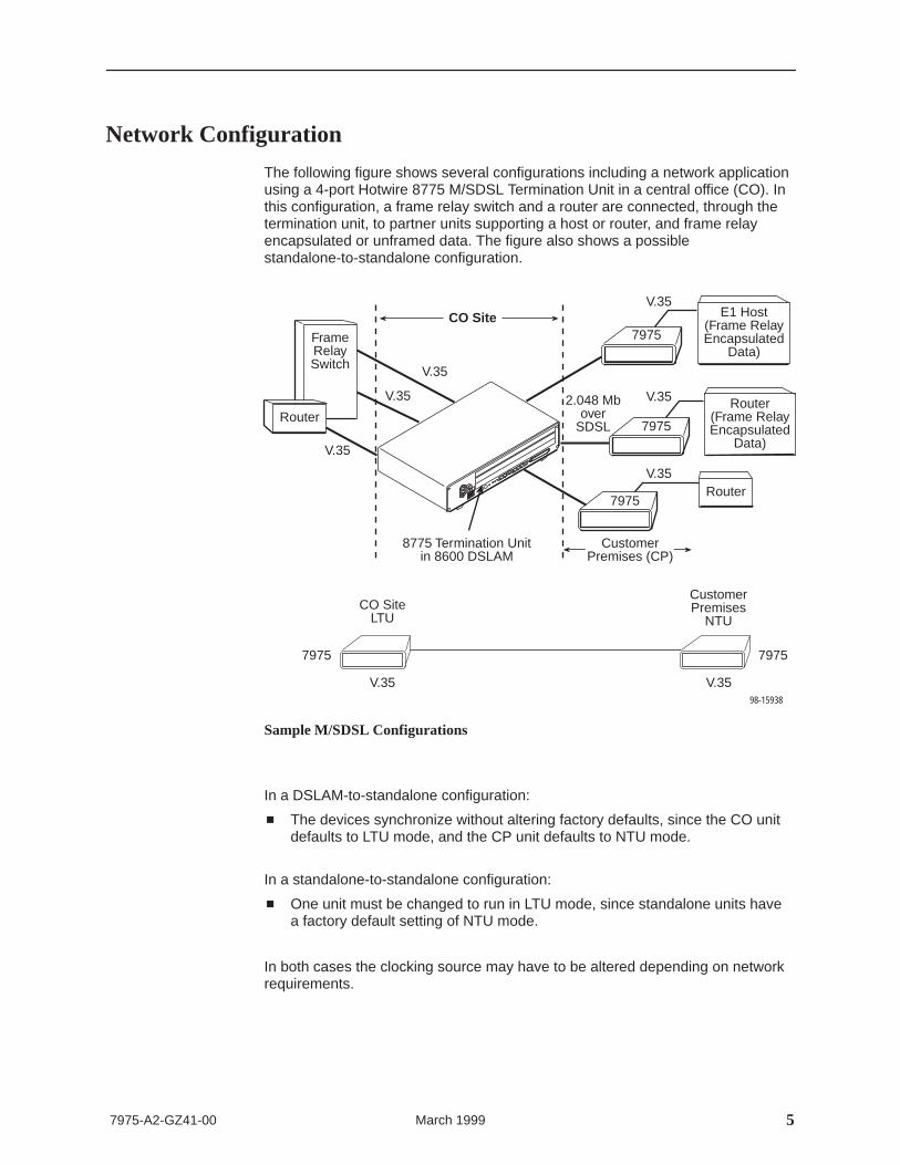
The following figure shows several configurations including a network applicationusing a 4-port Hotwire 8775 M/SDSL Termination Unit in a central office (CO). Inthis configuration, a frame relay switch and a router are connected, through thetermination unit, to partner units supporting a host or router, and frame relayencapsulated or unframed data. The figure also shows a possiblestandalone-to-standalone configuration.
FrameRelaySwitch
Router
E1 Host(Frame RelayEncapsulated
Data)
98-15938
Router(Frame RelayEncapsulated
Data)
V.35
V.35
V.35
Router2.048 Mb
overSDSL
V.35
V.35
V.35
8775 Termination Unitin 8600 DSLAM
CO Site7975
7975
7975
CustomerPremises (CP)
7975 7975
CustomerPremises
NTUCO Site
LTU
V.35 V.35
Sample M/SDSL Configurations
In a DSLAM-to-standalone configuration:
� The devices synchronize without altering factory defaults, since the CO unitdefaults to LTU mode, and the CP unit defaults to NTU mode.
In a standalone-to-standalone configuration:
� One unit must be changed to run in LTU mode, since standalone units havea factory default setting of NTU mode.
In both cases the clocking source may have to be altered depending on networkrequirements.
6 7975-A2-GZ41-00March 1999
Choosing a Configuration Mode
You can make configuration changes either through a VT100-compatible terminaland the unit’s Configuration menus or by manually changing switches on theboard. The unit comes configured to allow settings to be made through theConfiguration menus.
Configuring the Unit Using the Configuration Menus
You can use the Configuration menu branch of the unit to display or changeconfiguration option settings.
The Hotwire 7975 Standalone Termination Unit has two sets of configurationoption settings.
� The Current Configuration (the 7975 Standalone Termination Unit’s active setof configuration options)
� The Default Factory Configuration (a read-only configuration area containingthe factory default configuration options)
If the factory default settings do not support your network’s configuration, youcan customize the configuration options for your application. You must first load aconfiguration into the edit area.
To load a configuration option set into the configuration edit area, follow thismenu selection sequence:
Main Menu →Configuration (Load Configuration From)
Make a selection by placing the cursor at your choice and pressing Enter.
If you select . . . Then . . .
CurrentConfiguration
The selected configuration option set is loaded and theConfiguration Edit/Display menu screen appears.
Default FactoryConfiguration
The selected configuration option set is loaded and theConfiguration Edit/Display menu screen appears.
ConfigurationLoader
The Configuration Loader screen is displayed allowing you toupload or download configurations from a TFTP server.
77975-A2-GZ41-00 March 1999
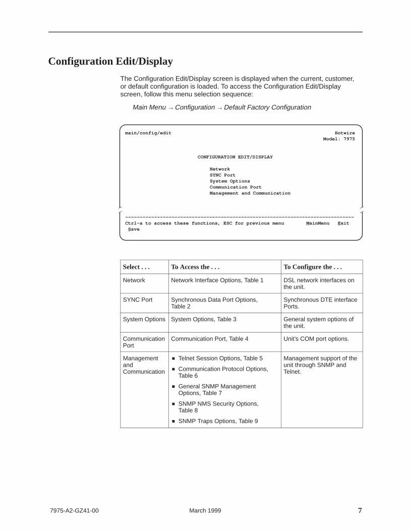
Configuration Edit/Display
The Configuration Edit/Display screen is displayed when the current, customer,or default configuration is loaded. To access the Configuration Edit/Displayscreen, follow this menu selection sequence:
Main Menu →Configuration →Default Factory Configuration
Î ÎÎ
main/config/edit HotwireModel: 7975
CONFIGURATION EDIT/DISPLAY
NetworkSYNC PortSystem OptionsCommunication PortManagement and Communication
–––––––––––––––––––––––––––––––––––––––––––––––––––––––––––––––––––––––––––––––Ctrl-a to access these functions, ESC for previous menu M ainMenu E xit S ave
Select . . . To Access the . . . To Configure the . . .
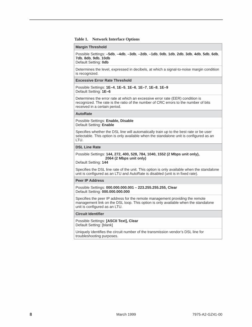
Determines the level, expressed in decibels, at which a signal-to-noise margin conditionis recognized.
Excessive Error Rate Threshold
Possible Settings: 1E–4, 1E–5, 1E–6, 1E–7, 1E–8, 1E–9Default Setting: 1E–6
Determines the error rate at which an excessive error rate (EER) condition isrecognized. The rate is the ratio of the number of CRC errors to the number of bitsreceived in a certain period.
AutoRate
Possible Settings: Enable, DisableDefault Setting: Enable
Specifies whether the DSL line will automatically train up to the best rate or be userselectable. This option is only available when the standalone unit is configured as anLTU.
DSL Line Rate
Possible Settings: 144, 272, 400, 528, 784, 1040, 1552 (2 Mbps unit only), 2064 (2 Mbps unit only)
Default Setting: 144
Specifies the DSL line rate of the unit. This option is only available when the standaloneunit is configured as an LTU and AutoRate is disabled (unit is in fixed rate).
Peer IP Address
Possible Settings: 000.000.000.001 – 223.255.255.255, ClearDefault Setting: 000.000.000.000
Specifies the peer IP address for the remote management providing the remotemanagement link on the DSL loop. This option is only available when the standaloneunit is configured as an LTU.
Circuit Identifier
Possible Settings: [ASCII Text], ClearDefault Setting: [blank]
Uniquely identifies the circuit number of the transmission vendor’s DSL line fortroubleshooting purposes.
97975-A2-GZ41-00 March 1999
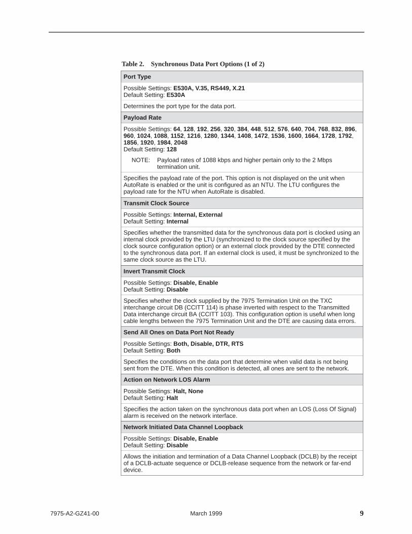
Table 2. Synchronous Data Port Options (1 of 2)
Port Type
Possible Settings: E530A, V.35, RS449, X.21Default Setting: E530A
NOTE: Payload rates of 1088 kbps and higher pertain only to the 2 Mbpstermination unit.
Specifies the payload rate of the port. This option is not displayed on the unit whenAutoRate is enabled or the unit is configured as an NTU. The LTU configures thepayload rate for the NTU when AutoRate is disabled.
Transmit Clock Source
Possible Settings: Internal, ExternalDefault Setting: Internal
Specifies whether the transmitted data for the synchronous data port is clocked using aninternal clock provided by the LTU (synchronized to the clock source specified by theclock source configuration option) or an external clock provided by the DTE connectedto the synchronous data port. If an external clock is used, it must be synchronized to thesame clock source as the LTU.
Invert Transmit Clock
Possible Settings: Disable, EnableDefault Setting: Disable
Specifies whether the clock supplied by the 7975 Termination Unit on the TXCinterchange circuit DB (CCITT 114) is phase inverted with respect to the TransmittedData interchange circuit BA (CCITT 103). This configuration option is useful when longcable lengths between the 7975 Termination Unit and the DTE are causing data errors.
Send All Ones on Data Port Not Ready
Possible Settings: Both, Disable, DTR, RTSDefault Setting: Both
Specifies the conditions on the data port that determine when valid data is not beingsent from the DTE. When this condition is detected, all ones are sent to the network.
Action on Network LOS Alarm
Possible Settings: Halt, NoneDefault Setting: Halt
Specifies the action taken on the synchronous data port when an LOS (Loss Of Signal)alarm is received on the network interface.
Network Initiated Data Channel Loopback
Possible Settings: Disable, EnableDefault Setting: Disable
Allows the initiation and termination of a Data Channel Loopback (DCLB) by the receiptof a DCLB-actuate sequence or DCLB-release sequence from the network or far-enddevice.
10 7975-A2-GZ41-00March 1999
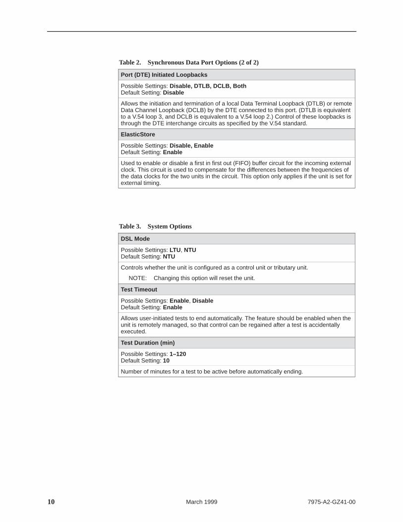
Table 2. Synchronous Data Port Options (2 of 2)
Port (DTE) Initiated Loopbacks
Possible Settings: Disable, DTLB, DCLB, BothDefault Setting: Disable
Allows the initiation and termination of a local Data Terminal Loopback (DTLB) or remoteData Channel Loopback (DCLB) by the DTE connected to this port. (DTLB is equivalentto a V.54 loop 3, and DCLB is equivalent to a V.54 loop 2.) Control of these loopbacks isthrough the DTE interchange circuits as specified by the V.54 standard.
ElasticStore
Possible Settings: Disable, EnableDefault Setting: Enable
Used to enable or disable a first in first out (FIFO) buffer circuit for the incoming externalclock. This circuit is used to compensate for the differences between the frequencies ofthe data clocks for the two units in the circuit. This option only applies if the unit is set forexternal timing.
Table 3. System Options
DSL Mode
Possible Settings: LTU, NTUDefault Setting: NTU
Controls whether the unit is configured as a control unit or tributary unit.
NOTE: Changing this option will reset the unit.
Test Timeout
Possible Settings: Enable , DisableDefault Setting: Enable
Allows user-initiated tests to end automatically. The feature should be enabled when theunit is remotely managed, so that control can be regained after a test is accidentallyexecuted.
Test Duration (min)
Possible Settings: 1–120Default Setting: 10
Number of minutes for a test to be active before automatically ending.
117975-A2-GZ41-00 March 1999
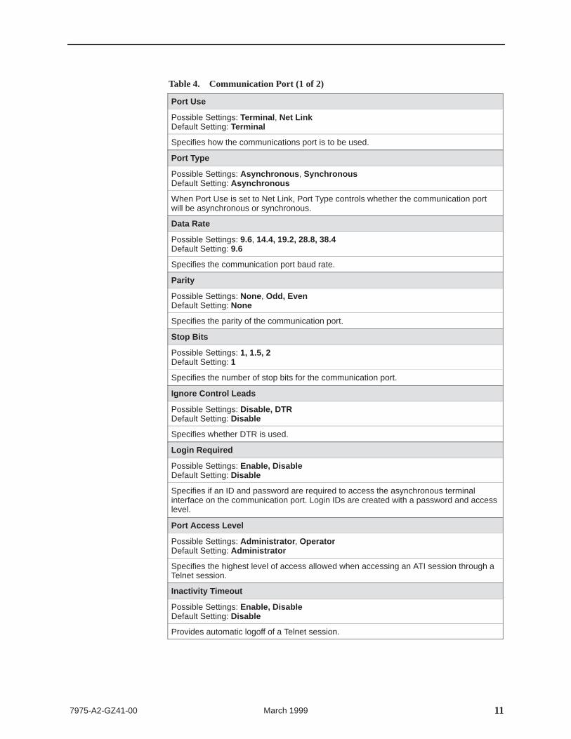
Table 4. Communication Port (1 of 2)
Port Use
Possible Settings: Terminal , Net LinkDefault Setting: Terminal
Specifies how the communications port is to be used.
Port Type
Possible Settings: Asynchronous , SynchronousDefault Setting: Asynchronous
When Port Use is set to Net Link, Port Type controls whether the communication portwill be asynchronous or synchronous.
Data Rate
Possible Settings: 9.6, 14.4, 19.2, 28.8, 38.4Default Setting: 9.6
Specifies the communication port baud rate.
Parity
Possible Settings: None , Odd, EvenDefault Setting: None
Specifies the parity of the communication port.
Stop Bits
Possible Settings: 1, 1.5, 2Default Setting: 1
Specifies the number of stop bits for the communication port.
Ignore Control Leads
Possible Settings: Disable, DTR Default Setting: Disable
Specifies whether DTR is used.
Login Required
Possible Settings: Enable, DisableDefault Setting: Disable
Specifies if an ID and password are required to access the asynchronous terminalinterface on the communication port. Login IDs are created with a password and accesslevel.
Port Access Level
Possible Settings: Administrator , OperatorDefault Setting: Administrator
Specifies the highest level of access allowed when accessing an ATI session through aTelnet session.
Inactivity Timeout
Possible Settings: Enable, DisableDefault Setting: Disable
Provides automatic logoff of a Telnet session.
12 7975-A2-GZ41-00March 1999
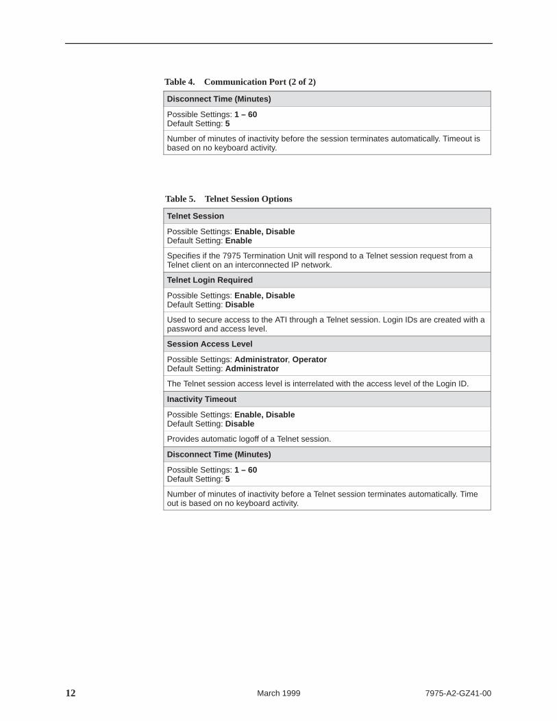
Table 4. Communication Port (2 of 2)
Disconnect Time (Minutes)
Possible Settings: 1 – 60Default Setting: 5
Number of minutes of inactivity before the session terminates automatically. Timeout isbased on no keyboard activity.
Table 5. Telnet Session Options
Telnet Session
Possible Settings: Enable, DisableDefault Setting: Enable
Specifies if the 7975 Termination Unit will respond to a Telnet session request from aTelnet client on an interconnected IP network.
Telnet Login Required
Possible Settings: Enable, DisableDefault Setting: Disable
Used to secure access to the ATI through a Telnet session. Login IDs are created with apassword and access level.
Session Access Level
Possible Settings: Administrator , OperatorDefault Setting: Administrator
The Telnet session access level is interrelated with the access level of the Login ID.
Inactivity Timeout
Possible Settings: Enable, DisableDefault Setting: Disable
Provides automatic logoff of a Telnet session.
Disconnect Time (Minutes)
Possible Settings: 1 – 60Default Setting: 5
Number of minutes of inactivity before a Telnet session terminates automatically. Timeout is based on no keyboard activity.
137975-A2-GZ41-00 March 1999
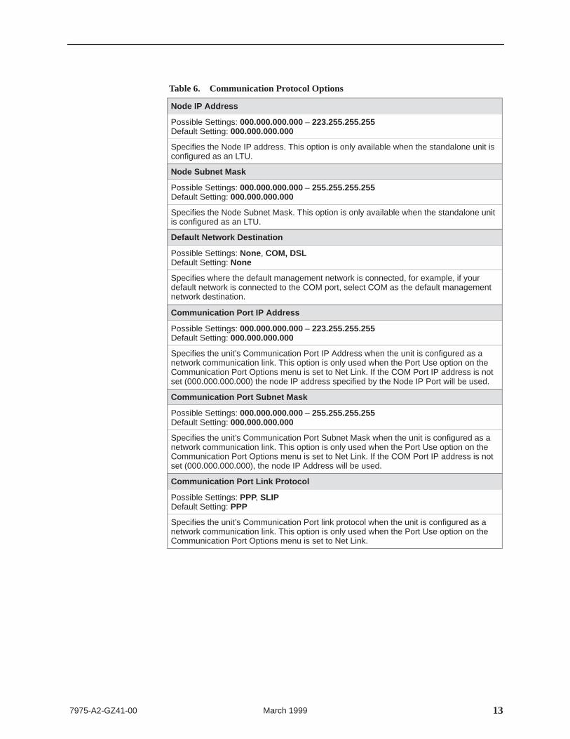
Table 6. Communication Protocol Options
Node IP Address
Possible Settings: 000.000.000.000 – 223.255.255.255Default Setting: 000.000.000.000
Specifies the Node IP address. This option is only available when the standalone unit isconfigured as an LTU.
Node Subnet Mask
Possible Settings: 000.000.000.000 – 255.255.255.255Default Setting: 000.000.000.000
Specifies the Node Subnet Mask. This option is only available when the standalone unitis configured as an LTU.
Default Network Destination
Possible Settings: None , COM, DSLDefault Setting: None
Specifies where the default management network is connected, for example, if yourdefault network is connected to the COM port, select COM as the default managementnetwork destination.
Communication Port IP Address
Possible Settings: 000.000.000.000 – 223.255.255.255Default Setting: 000.000.000.000
Specifies the unit’s Communication Port IP Address when the unit is configured as anetwork communication link. This option is only used when the Port Use option on theCommunication Port Options menu is set to Net Link. If the COM Port IP address is notset (000.000.000.000) the node IP address specified by the Node IP Port will be used.
Communication Port Subnet Mask
Possible Settings: 000.000.000.000 – 255.255.255.255Default Setting: 000.000.000.000
Specifies the unit’s Communication Port Subnet Mask when the unit is configured as anetwork communication link. This option is only used when the Port Use option on theCommunication Port Options menu is set to Net Link. If the COM Port IP address is notset (000.000.000.000), the node IP Address will be used.
Communication Port Link Protocol
Possible Settings: PPP, SLIPDefault Setting: PPP
Specifies the unit’s Communication Port link protocol when the unit is configured as anetwork communication link. This option is only used when the Port Use option on theCommunication Port Options menu is set to Net Link.
14 7975-A2-GZ41-00March 1999
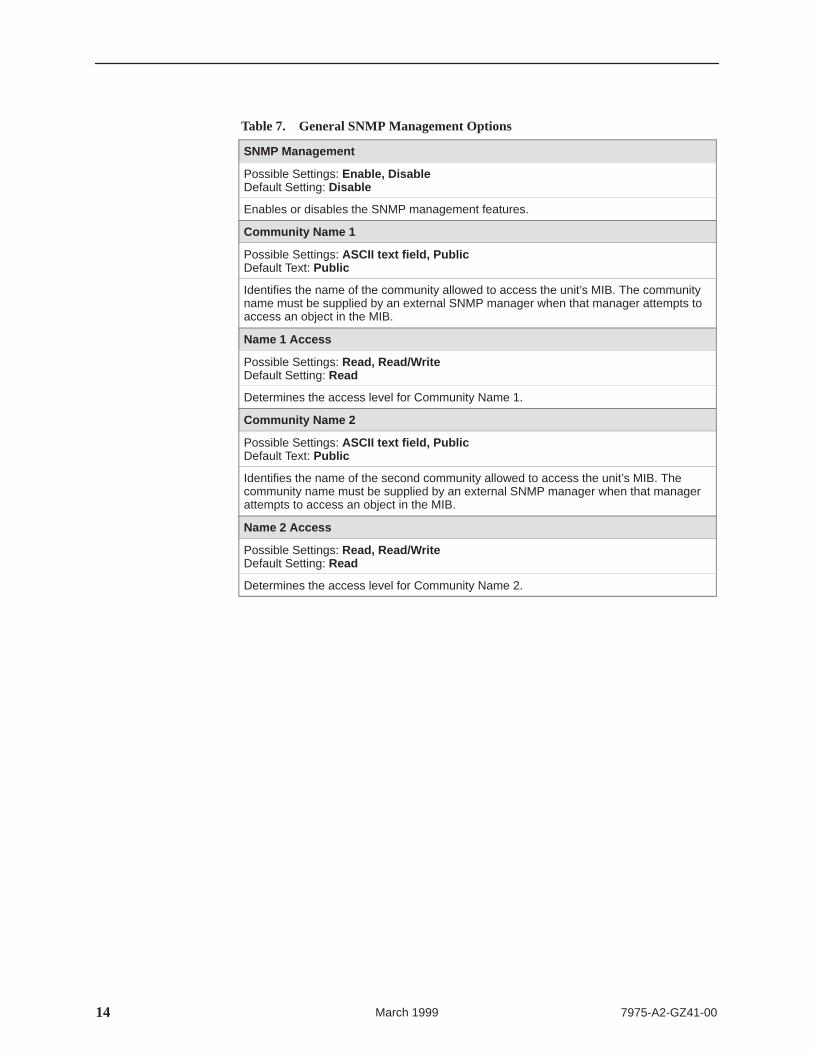
Table 7. General SNMP Management Options
SNMP Management
Possible Settings: Enable, DisableDefault Setting: Disable
Enables or disables the SNMP management features.
Community Name 1
Possible Settings: ASCII text field, PublicDefault Text: Public
Identifies the name of the community allowed to access the unit’s MIB. The communityname must be supplied by an external SNMP manager when that manager attempts toaccess an object in the MIB.
Name 1 Access
Possible Settings: Read, Read/WriteDefault Setting: Read
Determines the access level for Community Name 1.
Community Name 2
Possible Settings: ASCII text field, PublicDefault Text: Public
Identifies the name of the second community allowed to access the unit’s MIB. Thecommunity name must be supplied by an external SNMP manager when that managerattempts to access an object in the MIB.
Name 2 Access
Possible Settings: Read, Read/WriteDefault Setting: Read
Determines the access level for Community Name 2.
157975-A2-GZ41-00 March 1999
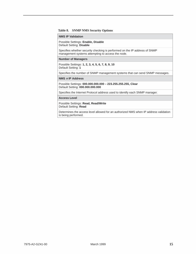
Table 8. SNMP NMS Security Options
NMS IP Validation
Possible Settings: Enable, DisableDefault Setting: Disable
Specifies whether security checking is performed on the IP address of SNMPmanagement systems attempting to access the node.
Specifies the number of SNMP management systems that can send SNMP messages.
NMS n IP Address
Possible Settings: 000.000.000.000 – 223.255.255.255, ClearDefault Setting: 000.000.000.000
Specifies the Internet Protocol address used to identify each SNMP manager.
Access Level
Possible Settings: Read, Read/WriteDefault Setting: Read
Determines the access level allowed for an authorized NMS when IP address validationis being performed.
16 7975-A2-GZ41-00March 1999
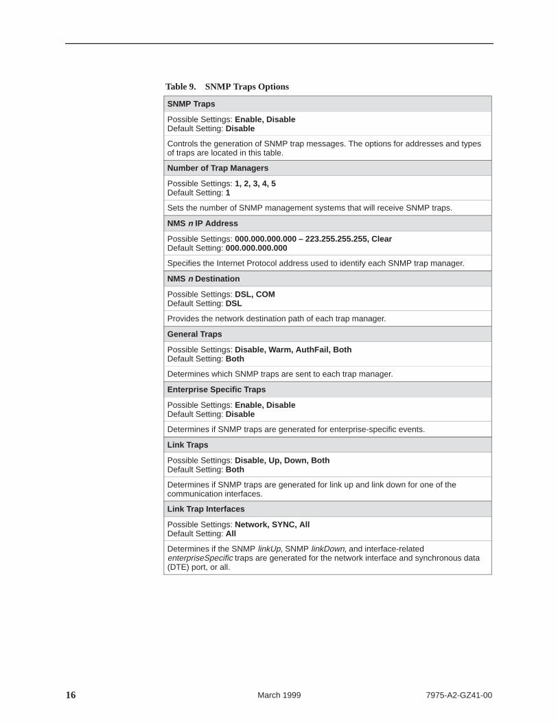
Table 9. SNMP Traps Options
SNMP Traps
Possible Settings: Enable, DisableDefault Setting: Disable
Controls the generation of SNMP trap messages. The options for addresses and typesof traps are located in this table.
Number of Trap Managers
Possible Settings: 1, 2, 3, 4, 5Default Setting: 1
Sets the number of SNMP management systems that will receive SNMP traps.
NMS n IP Address
Possible Settings: 000.000.000.000 – 223.255.255.255, ClearDefault Setting: 000.000.000.000
Specifies the Internet Protocol address used to identify each SNMP trap manager.
NMS n Destination
Possible Settings: DSL, COMDefault Setting: DSL
Provides the network destination path of each trap manager.
General Traps
Possible Settings: Disable, Warm, AuthFail, BothDefault Setting: Both
Determines which SNMP traps are sent to each trap manager.
Enterprise Specific Traps
Possible Settings: Enable, DisableDefault Setting: Disable
Determines if SNMP traps are generated for enterprise-specific events.
Link Traps
Possible Settings: Disable, Up, Down, BothDefault Setting: Both
Determines if SNMP traps are generated for link up and link down for one of thecommunication interfaces.
Link Trap Interfaces
Possible Settings: Network, SYNC, AllDefault Setting: All
Determines if the SNMP linkUp, SNMP linkDown, and interface-relatedenterpriseSpecific traps are generated for the network interface and synchronous data(DTE) port, or all.
177975-A2-GZ41-00 March 1999
Configuring the Unit Using the Internal Switches
If desired, use internal Switchpacks S1 and S2 to manually configure the unit.
! HANDLING PRECAUTIONS FORSTATIC-SENSITIVE DEVICESThis product is designed to protect sensitive components fromdamage due to electrostatic discharge (ESD) during normal operation.When performing installation procedures, however, take proper staticcontrol precautions to prevent damage to equipment. If you are notsure of the proper static control precautions, contact your nearestsales or service representative.
� Procedure
To configure the unit using internal Switchpacks S1 and S2:
1. Power down the unit and disconnect the power supply.
2. Remove the enclosure cover:
— Insert a small, flat screwdriver blade into the slots on one side of thecover and push to free the inner latches
— Lift off the cover to expose the circuit board
3. Locate Switchpack S1.
4. Set switch 1 on Switchpack S1 to ON to enable Switchpacks 1 and 2.
5. After you enable the switchpacks, you must set the switches to your desiredconfiguration.
6. Replace and secure the cover.
7. Power up the board to reset and enable the new configuration.
496-15104
18 7975-A2-GZ41-00March 1999
Switchpack Locations
Use the following illustration to locate Switchpacks S1 and S2.
98-15937
Switchpack S1 & S2
Front
S2
Rear
S167
8
ON1
23
45
67
8
ON1
23
45
Hotwire 7975 Standalone Termination Unit Switchpack Locations
197975-A2-GZ41-00 March 1999
Switchpack Definitions
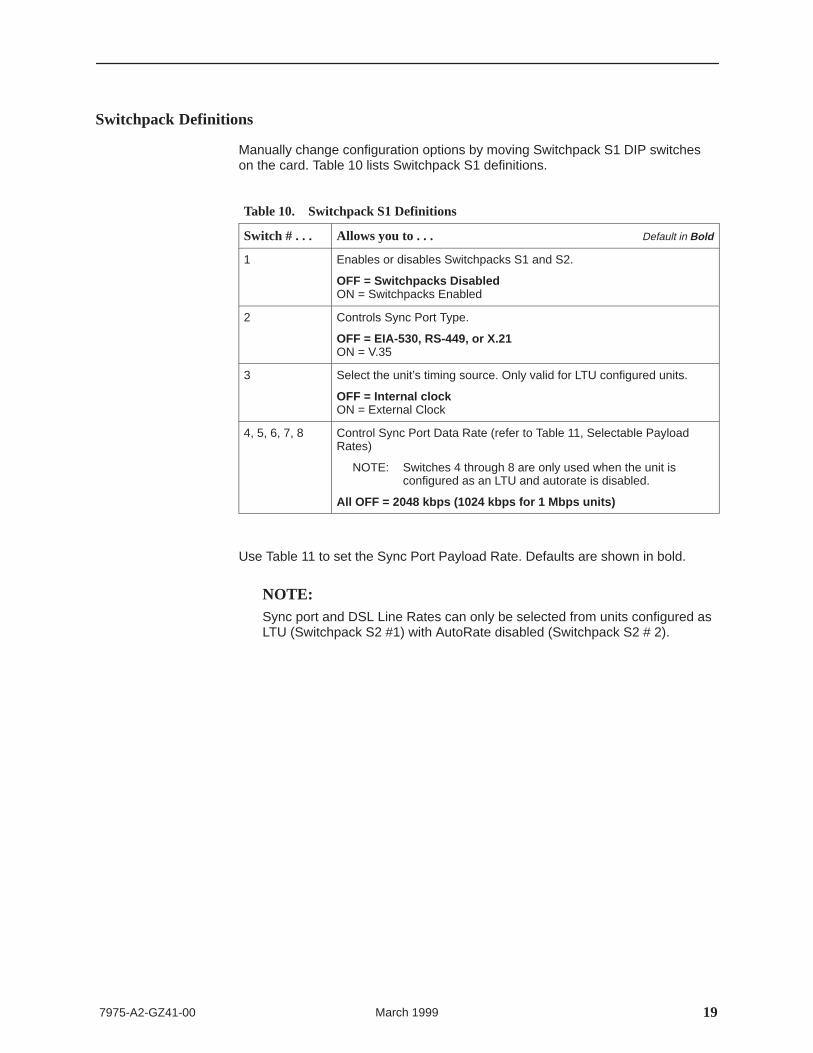
Manually change configuration options by moving Switchpack S1 DIP switcheson the card. Table 10 lists Switchpack S1 definitions.
Table 10. Switchpack S1 Definitions
Switch # . . . Allows you to . . . Default in Bold
1 Enables or disables Switchpacks S1 and S2.
OFF = Switchpacks DisabledON = Switchpacks Enabled
2 Controls Sync Port Type.
OFF = EIA-530, RS-449, or X.21ON = V.35
3 Select the unit’s timing source. Only valid for LTU configured units.
OFF = Internal clockON = External Clock
4, 5, 6, 7, 8 Control Sync Port Data Rate (refer to Table 11, Selectable PayloadRates)
NOTE: Switches 4 through 8 are only used when the unit isconfigured as an LTU and autorate is disabled.
All OFF = 2048 kbps (1024 kbps for 1 Mbps units)
Use Table 11 to set the Sync Port Payload Rate. Defaults are shown in bold.
NOTE:Sync port and DSL Line Rates can only be selected from units configured asLTU (Switchpack S2 #1) with AutoRate disabled (Switchpack S2 # 2).
20 7975-A2-GZ41-00March 1999
Table 11. Selectable Payload Rates (Switches 4–8 on Switchpack S1)
Switch Number AssociatedDSL Line
Sync Port Payload Rate 8 7 6 5 4DSL Li neRate
2048 kbps (32 x 64) OFF OFF OFF OFF OFF 2064 kbps
1984 kbps (31 x 64) ON ON ON ON ON 2064 kbps
1920 kbps (30 x 64) ON ON ON ON OFF 2064 kbps
1856 kbps (29 x 64) ON ON ON OFF ON 2064 kbps
1792 kbps (28 x 64) ON ON ON OFF OFF 2064 kbps
1728 kbps (27 x 64) ON ON OFF ON ON 2064 kbps
1664 kbps (26 x 64) ON ON OFF ON OFF 2064 kbps
1600 kbps (25 x 64) ON ON OFF OFF ON 2064 kbps
1536 kbps (24 x 64) ON ON OFF OFF OFF 1552 kbps
1472 kbps (23 x 64) ON OFF ON ON ON 1552 kbps
1408 kbps (22 x 64) ON OFF ON ON OFF 1552 kbps
1344 kbps (21 x 64) ON OFF ON OFF ON 1552 kbps
1280 kbps (20 x 64) ON OFF ON OFF OFF 1552 kbps
1216 kbps (19 x 64) ON OFF OFF ON ON 1552 kbps
1152 kbps (18 x 64) ON OFF OFF ON OFF 1552 kbps
1088 kbps (17 x 64) ON OFF OFF OFF ON 1552 kbps
1024 kbps (16 x 64) ON OFF OFF OFF OFF 1040 kbps
960 kbps (15 x 64) OFF ON ON ON ON 1040 kbps
896 kbps (14 x 64) OFF ON ON ON OFF 1040 kbps
832 kbps (13 x 64) OFF ON ON OFF ON 1040 kbps
768 kbps (12 x 64) OFF ON ON OFF OFF 784 kbps
704 kbps (11 x 64) OFF ON OFF ON ON 784 kbps
640 kbps (10 x 64) OFF ON OFF ON OFF 784 kbps
576 kbps (9 x 64) OFF ON OFF OFF ON 784 kbps
512 kbps (8 x 64) OFF ON OFF OFF OFF 528 kbps
448 kbps (7 x 64) OFF OFF ON ON ON 528 kbps
384 kbps (6 x 64) OFF OFF ON ON OFF 400 kbps
320 kbps (5 x 64) OFF OFF ON OFF ON 400 kbps
256 kbps (4 x 64) OFF OFF ON OFF OFF 272 kbps
192 kbps (3 x 64) OFF OFF OFF ON ON 272 kbps
128 kbps (2 x 64) OFF OFF OFF ON OFF 144 kbps
64 kbps (1 x 64) OFF OFF OFF OFF ON 144 kbps
NOTE:The 1 Mbps unit Payload Rate has a default of 1024 kbps (all OFF).
––––
––––
––––
–––
2 M
bps
Uni
ts O
nly
––––
––––
––––
––––
–
217975-A2-GZ41-00 March 1999
Table 12 lists Switchpack S2 definitions.
Table 12. Switchpack S2 Definitions
Switch # . . . Allows you to . . . Default in Bold
1 Control whether the unit is an LTU or an NTU.
OFF = NTUON = LTU
2 Control enabling and disabling of the AutoRate capability.
OFF = AutoRate EnabledON = AutoRate Disabled
3, 4, 5 Select one of eight preset DSL line rates (refer to Table 13).
All OFF = 2064
6 Control enabling and disabling of the first in, first out (FIFO) buffercircuit (Elastic Store) for the incoming external clock.
OFF = Elastic Store EnabledON = Elastic Store Disabled
7 Not used
8 Emergency Use Only – The Hotwire 7975 has two banks of flashmemory used to hold executable firmware. This switch allows you toswitch between the two versions of firmware. This switch isindependent from the position of Switch 1 on Switchpack S1(switchpack enable/disable).
OFF = Current FirmwareON = Previous Firmware
Use Table 13 to set the DSL Line Rate. Defaults are shown in bold.
Table 13. DSL Line Rate, Switches 3–5 on Switchpack S2
Switch Position
5 4 3 DSL Line Rate
OFF OFF ON 144 kbps
OFF ON OFF 272 kbps
OFF ON ON 400 kbps
ON OFF OFF 528 kbps
ON OFF ON 784 kbps
ON ON OFF 1040 kbps
ON ON ON 1552 kbps
OFF OFF OFF 2064 kbps
22 7975-A2-GZ41-00March 1999
! Important Safety Instructions
1. Read and follow all warning notices and instructions marked on the productor included in the manual.
2. Input power to this product must be provided by one of the following: (1) a ULListed/CSA Certified power source with a Class 2 or Limited Power Source(LPS) output for use in North America; or (2) a 24 Vdc National Electric Code(NEC) ANSI/NFPA 70/Canadian Electric Code (CEC) Class 2 circuit installedin accordance with articles 110-16, 110-17, and 110-18 of the NEC, andarticles 2-308, 2-310, 2-312, 2-314, 2-200, and 2-202 of the CEC, or (3) aSafety Extra Low Voltage (SELV) power source with a maximum availableoutput of less than 240 VA, certified for use in the country of installation.
3. Slots and openings in the cabinet are provided for ventilation. To ensurereliable operation of the product and to protect it from overheating, theseslots and openings must not be blocked or covered.
4. Do not allow anything to rest on the power cord and do not locate the productwhere persons will walk on the power cord.
5. Do not attempt to install or service this product yourself, as opening orremoving covers may expose you to dangerous high voltage points or otherrisks. Refer all installation and servicing to qualified service personnel.
6. General purpose cables are provided with this product. Special cables, whichmay be required by the regulatory inspection authority for the installation site,are the responsibility of the customer.
7. When installed in the final configuration, the product must comply with theapplicable Safety Standards and regulatory requirements of the country inwhich it is installed. If necessary, consult with the appropriate regulatoryagencies and inspection authorities to ensure compliance.
8. A rare phenomenon can create a voltage potential between the earthgrounds of two or more buildings. If products installed in separate buildingsare interconnected , the voltage potential may cause a hazardous condition.Consult a qualified electrical consultant to determine whether or not thisphenomenon exists and, if necessary, implement corrective action prior tointerconnecting the products.
9. In addition, if the equipment is to be used with telecommunications circuits,take the following precautions:
— Never install telephone wiring during a lightning storm.
— Never install telephone jacks in wet locations unless the jack isspecifically designed for wet locations.
— Never touch uninsulated telephone wires or terminals unless thetelephone line has been disconnected at the network interface.
— Use caution when installing or modifying telephone lines.
— Avoid using a telephone (other than a cordless type) during an electricalstorm. There may be a remote risk of electric shock from lightning.
— Do not use the telephone to report a gas leak in the vicinity of the leak.
237975-A2-GZ41-00 March 1999
EMI Warnings
! WARNING:This equipment has been tested and found to comply with the limitsfor a Class A digital device, pursuant to Part 15 of the FCC rules. Theselimits are designed to provide reasonable protection against harmfulinterference when the equipment is operated in a commercialenvironment. This equipment generates, uses, and can radiate radiofrequency energy and, if not installed and used in accordance with theinstruction manual, may cause harmful interference to radiocommunications. Operation of this equipment in a residential area islikely to cause harmful interference in which case the user will berequired to correct the interference at his own expense.
The authority to operate this equipment is conditioned by therequirements that no modifications will be made to the equipmentunless the changes or modifications are expressly approved byParadyne Corporation.
! WARNING:To Users of Digital Apparatus in Canada:
This Class A digital apparatus meets all requirements of the Canadianinterference-causing equipment regulations.
Cet appareil numérique de la classe A respecte toutes les exigences durèglement sur le matérial brouilleur du Canada.
Warranty, Sales, Service, and Training Information
Contact your local sales representative, service representative, or distributordirectly for any help needed. For additional information concerning warranty,sales, service, repair, installation, documentation, training, distributor locations, orParadyne worldwide office locations, use one of the following methods:
� Internet: Visit the Paradyne World Wide Web site at www.paradyne.com .(Be sure to register your warranty there. Select Service & Support →Warranty Registration.)
� Telephone: Call our automated system to receive current information by faxor to speak with a company representative.
— Within the U.S.A., call 1-800-870-2221
— Outside the U.S.A., call 1-727-530-2340
24 7975-A2-GZ41-00March 1999
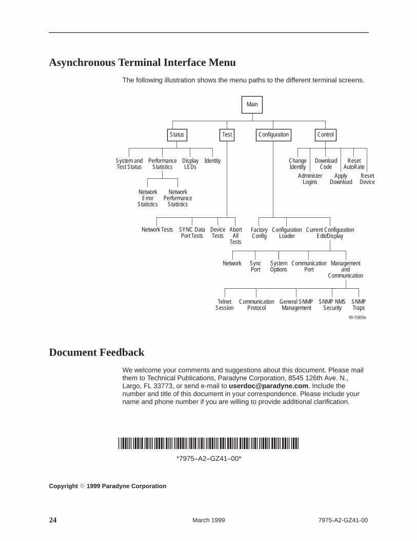
Asynchronous Terminal Interface Menu
The following illustration shows the menu paths to the different terminal screens.
Main
Status Test
System andTest Status
PerformanceStatistics
DisplayLEDs
Identity
NetworkError
Statistics
NetworkPerformance
Statistics
Configuration Control
FactoryConfig
ConfigurationLoader
Current ConfigurationEdit/Display
SystemOptions
CommunicationPort
Managementand
Communication
ChangeIdentity
AdministerLogins
DownloadCode
ApplyDownload
ResetAutoRate
Network Tests SYNC DataPort Tests
DeviceTests
AbortAll
Tests
99-15859a
ResetDevice
Network SyncPort
General SNMPManagement
SNMP NMSSecurity
CommunicationProtocol
TelnetSession
SNMPTraps
Document Feedback
We welcome your comments and suggestions about this document. Please mailthem to Technical Publications, Paradyne Corporation, 8545 126th Ave. N.,Largo, FL 33773, or send e-mail to [email protected] . Include thenumber and title of this document in your correspondence. Please include yourname and phone number if you are willing to provide additional clarification.