Hough-transform system with optical anamorphicpreprocessing and digital postprocessing
Carlos Ferreira, Antonio Moya, Tomasz Szoplik, and Juan Domingo
A modification of the optical Hough transformer [Appl. Opt. 25, 2734-2738 (1986)] is proposed. Aninput image is optically preprocessed to obtain an anamorphic magnified image. The anamorphicmagnification leads to improved accuracy of the output plane parameter 0 determination by means of asimple version of a Hough transformer. Then, the output signal is digitally postprocessed to obtainsubpixel resolution in the p parameter dimension. A description of the method and the experimentalresults is presented.
The Hough transform (HT) maps straight lines in theinput image (x, y) plane into points in the output(0, p) plane.1 The transform was extended to thecase of curves by Duda and Hart 2 and Deans.3During the first 20 years of its existence the HT wasobtained digitally. Then, in 1982 Barrett proposedan incoherent flying spot scanner for optical imple-mentation of the Radon transform.4 Since the math-ematical similarity of the Radon and Hough trans-forms was known,3 soon after, a coherent opticalsystem for the HT implementation was proposed byEichmann and Dong,5 and then an incoherent opticalsystem was proposed by Gindi and Gmitro.6 Thencame both the coherent and the incoherent improvedsystems of Steier and Shori.7 All of the above-mentioned optical systems employed mechanicallymoving elements. The HT was also accomplished inholographic systems by Ambs et al.8 9 and Richards etal.'0 The space-variant transform kernel was real-ized in parallel by means of a two-dimensional (2-D)array of holograms, each of them having a differentimpulse response.
In recent years the HT has been used in variousapplicationsll1" 2 such as detection of lines and curvesin images2 7 (more specifically, target trajectory track-
C. Ferreira and A. Moya are with the Department Interuniversi-tari d'Optica, 46100 Burjassot, Spain; T. Szoplik is with theInstytut Geofizyki, Uniwersytet Warszawski, 02-093 Warsaw, Po-land. J. Domingo is with the Departament d'Electr6nica i Infor-matica, 46100 Burjassot, Spain.
ing13- 5), machine vision systems,10" 6 and patternrecognition.1718 Casasent and Richards' 6 proved thatin an optical HT system the intensity of an outputspot in the parameter plane is proportional to thelength of the corresponding line in the object plane.Then Richards and Casasent19 theoretically showedthat the location of a line in an input image can bedetermined from the shape of the HT pattern aroundthe HT peak. A study of numerical HT performancein the case of noisy signals and of multisignals wasmade by Maitre.20 The study was limited to the caseof a continuous input image space.
In holographic HT systems an input image analysiscan be made in real time. Ambs et al.9 reported on aspace-variant optical processor with a bank of256 x 256 space-multiplexed subholograms that per-mitted discrimination of similar objects of discrete 0angular line positions and discrete p values. Eachsubhologram of 250 x 250 m size stored a space-bandwidth product of approximately 6.6 x 10⁴. Aset of subholograms recorded in a photographic mate-rial was used for both line and curve detection ininput images. However, a complicated hybrid opto-electronic acousto-optic system was needed to recorda subhologram matrix and an optical processor wasneeded for input image analysis. It is known19 thatin product inspection applications the 0 values of theHT peaks are often expected within a narrow rangeand that only several HT slices at different 0 areneeded. Therefore the motivation of our researchwas a need to find a simple, optical method forimproved accuracy of the 0 and p determination.As suggested by Richards and Casasent, 9 an exactshape of the HT peak and its vicinity is useful to find aposition of a line in an input image.
We present a modification of the optical Houghtransformer proposed by Steier and Shori.7 Our aimis to improve the accuracy of determination of both 0and p in the output plane. The modification consistsof the introduction of an anamorphic optical prepro-cessor2 ' that provides a distorted image of the objectat the input plane of the Hough transformer. Owingto nonuniform magnifications in the x and y direc-tions, the angular relations in the input image arechanged, and better resolution of 0 is possible.Then, the HT is obtained optically. The output isrecorded with a CCD camera and fed to a computer.The output images are digitally processed to obtainsubpixel resolution of p with a method similar to thatdiscussed by Seitz.22 Finally, we consider differenterror sources that influence the determination of 0and p of the line position. Experimental results andconclusions are presented.
Description of Method
Anamorphic Optical Preprocessor
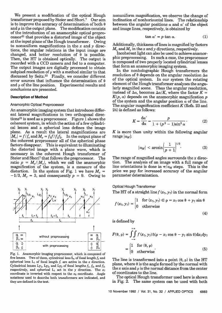
An anamorphic imaging system that introduces differ-ent lateral magnifications in two orthogonal direc-tions2l is used as a preprocessor. Figure 1 shows thecoherent system, in which the action of a few cylindri-cal lenses and a spherical lens defines the imageplane. As a result the lateral magnifications areMxI = f/fx andM, = f2f/fAf3. Intheoutputplaneof
the coherent preprocessor all of the spherical phasefactors disappear. This is equivalent to illuminatingthe distorted image with a plane wave, which isnecessary in the coherent Hough transformer ofSteier and Shori7 that follows the preprocessor. Theratio p = My/lMxl, which we call the anamorphicmagnification of the system, is a measure of thedistortion. In the system of Fig. 1 we have M =-1/3, My = 3, and consequently p = 9. Owing to
nonuniform magnification, we observe the change ofinclination of nonhorizontal lines. The relationshipbetween the angular positions a and a' of the objectand image lines, respectively, is obtained by
tan (x' = p tan a. (1)
Additionally, thickness of lines is magnified by factorsM. and My in the x and y directions, respectively.
Incoherent light can also be used to achieve anamor-phic preprocessing. In such a case, the preprocessoris composed of two properly located cylindrical lensesthat form an anamorphic imaging system.
In the nonholographic Hough transformers theresolution of 0 depends on the angular resolution Au.of the optical system. In our system the rotatingelement of the Hough transformer analyzes the angu-larly magnified scene. Thus the angular resolution,instead of Aa, becomes Aa/K, where the factor K =K(p, a) depends on the anamorphic magnification pof the system and the angular position a of the line.The angular magnification coefficient K (Refs. 23 and24) is defined as follows:
da' PK=da 1+(p2 1)sin2 aX (2)
K is more than unity within the following angularrange aMI:
I aMI < arcsin 1 1/2amI ae p +1) (3)
The range of magnified angles surrounds the x direc-tion. The analysis of an image with a full range ofline orientations is done in r/aM steps. This is theprice we pay for increased accuracy of the angularparameter determination.
Yo Yi Y2 Y3
X Ly LY2
fl I f + f2fX
I Yx
/X2 X3
/4X4LX_---
7S
f2 + f3
Y5 Y6 Y7
LyLiX4 /X 5 X6
f3___ _ f I ff3 I f X I
PH = without preprocessing = .
ax with preprocessing |
Fig. 1. Anamorphic imaging preprocessor, which is composed offive lenses. Two of them, cylindrical lens L. of focal length f andspherical lens L of focal length f are active in the x direction.Cylindrical lenses Ly1, Ly2, and Ly3 of focal lengths f, f&, and f&,respectively, and spherical L act in the y direction. The X7
coordinate is inverted with respect to the x0 coordinate. Anglenotations used to describe both transformers are indicated, andthey are defined in the text.
Optical Hough Transformer
The HT of a straight line f (X7, y7) in the normal form
f (X7, Y 7 ) = {ofor (X7, y7) E p = X7 cos 0 + Y7 sin 0
otherwise
(4)
is defined by
F(0, p) = ff f (X7, y7 ) 6(p - x7 cos 0 - y7 sin 0)dx7 dy7
1 for (0, p)
l0 otherwise (5)
The line is transformed into a point (0, p) in the HTplane, where 0 is the angle formed by the normal withthe x axis and p is the normal distance from the centerof coordinates to the line.
The optical Hough transformer used here is shownin Fig. 2. The same system can be used with both
Fig. 2. Modified Hough transformer. In the xay8 plane there is aspherical lens, LH, of focal length fH and a cylindrical lens, Lc, offocal length fc. Lens Lc is a rotating element.
coherent and incoherent illumination. The stretchedimage of the input is processed by the optical systemof two lenses: a cylindrical lens LC with focal lengthfc and a spherical lens LH with focal length fH; in thesimplest case f = H. In our experiment, H > fc,which results in a magnification of the output signalin the x9y9 plane by a factor of HI fc.
All nonholographic Hough transformers containmechanically moving parts. Therefore the systemproposed is not better. Here the HT is performed ina different way than before, however. The objectplaced in the x0y0 input plane is motionless. So is theanamorphic preprocessor. Thus the distorted imagewith properly changed angular relations [see Eq. (1)]preserves its fixed position. The angular scanning ofthe image entering into the Hough transformer is dueto rotation by an angle I' of the cylindrical lens LCplaced in the x&y8 plane. Angle a ' values correspondwith angle a' values. Consequently, rotation by astep angle AP' is equivalent to rotation of the object inthe x0y0 plane by the angle a = arctan(tan Af3'/p).
In the x9y9 output plane we obtain inverted imagesof lines along directions parallel to subsequent posi-tions of the active axis of the cylindrical lens Lc. Inthe perpendicular directions we have one-dimen-sional (1-D) Fourier spectra of the input. 'Outputsignals are recorded with a CCD-array camera andstored in the computer memory.
In the incoherent system, only a part of the inten-sity of a line hits the detector. This can decrease thesignal-to-noise ratio, but the incoherent system ismore practical.
Digital Postprocessing
The HT parameter plane can be detected in two ways.The first method is to use a CCD line of detectors thatrotates similarly as the cylindrical lens L and ispositioned along its active direction. In the secondmethod the whole HT parameter plane is recordedwith a CCD array of detectors. Output signals arerecorded at every angular position of the cylindricallens.
The accuracy of the p determination depends on thepixel size in the CCD-array camera and on the size ofthe light spot in the output plane. We estimated theline-spread function in the Hough transformer ofSteier and Shori. For the case of = 0.6 um andlenses with apertures of 5 cm and focal lengths of 20cm, the line-spread function is 2-3 m. In practice,
however, the input line cannot be considered as a 2-Ddelta function. Therefore its 1-D image is widerthan 2-3 pim. A typical pixel size in a CCD array isapproximately 10 plm 10 [im with a separationbetween pixels of approximately 10 m. Thus theresolution ability of a CCD camera matches closelythe actual width of the image of a line that hasthickness equal to a grain size in a typical photo-graphic material used to record an input image. Inour method, however, the line image is magnified afew times. As a consequence, the line image isrecorded by a few neighboring pixels. To exactlylocate the light spot position, we use the algorithmdescribed by Seitz.22 This permits us to achievesubpixel accuracy in estimating p without using theoptical system modulation transfer function.
The idea of the algorithm is presented in Fig.3. Signals from one line in the CCD camera areshown in Fig. 3(a). They form a bell-like distribu-tion with random deviations. The lowest of a fewmaximum values obtains the relative zero level.Then the center of mass of all values above this zerolevel is calculated [Fig. 3(b)]. We use a parabolicleast-square-error interpolation. This method of in-terpolation is one of several possible.
Theoretical Accuracy of 0 and p Measurements
The accuracy of determination of 0 and p depends onthe precision of the step-rotating holder on which lensLC is mounted and on the pixel size in the CCD
a
0a
signalvalue
0
a
I I Th
| t I 0 level1 2 3 4 5 6 7 8 9
(a)
signalvalue
(b)
Fig. 3. Subpixel resolution is obtained by calculation of the centerof mass of maximum signals: (a) The lowest of a few maximumsignals obtains the relative zero level. (b) The parabolic interpola-tion by means of least-mean-square error is used to calculate theposition of the center of mass.
camera that is used. Our aim is to improve theaccuracy of the 0 determination by means of theanamorphic preprocessor. The result of nonlinearmagnification of angular range aXmI [See Eq. (3)] isthat we are able to sample smaller input angularregions with the same step rotator. As in the case ofaccurate angular spectral analysis with an anamor-phic Fourier transformer,23' here also we introducethe notion of the effective angular aperture A'IK(p, a), which is equal to the step angle divided bythe angular magnification coefficient.
Let us consider an object transparency containingone line, as shown in Fig. 4(a). The line is c = C2 - lwide and b = b2 - b long. Figure 4(b) shows theanamorphically magnified image of the line in thex7y7 plane. The image is wider than the original line.It has distorted ends and its angular position is a'.Figure 4(c) shows 1-D images of the line observed intwo directions parallel to the active axis of thecylindrical lens Lc. For a vertical position of Lc the1-D image length along the output y9 axis is pL. Foran arbitrary angle 13' between the cylindrical lensactive direction and the input plane x0 axis the i-Doutput image length is
11p'=
(a)
(b)
x7
(C)
1-D images
fH[MyCOS13(btana +c) - M. JsinP'(b - ctanca)]'
fc(l + tan2 L)/2
(6)
If the cylindrical lens is rotated by an angle 13' = a'with respect to the x0 axis, then the smallest 1-Dimage length Rat is observed [also shown in Fig. 4(c)].In this case, the line direction in the x7y7 plane isperpendicular to the active direction of the Lc lens.Then Eq. (6) becomes
fHlMX MYc(1 + tan 2 a )/2
=c(Mx2 + M 2 tan2 )l/2
However, the accuracy of the cylindrical lens positionis limited to the A13' rotator step angle. Let us, then,introduce a parameter oa that permits us to obtainquantitative information about the error made in theHough space 0 determination. It denotes the small-est difference in the output signal lengths, which
Yg
x9
[1\\x;
Fig. 4. Schematics of the system performance: (a) an input linein the xoyo plane, (b) its anamorphic image in the x7y7 plane, (c) two1-D images in the x9y9 plane. The longer image is obtained by thevertical position of lens Lc, and the shorter image is obtained bylens Lc rotated by an angle 3' = '.
a in the x0y0 plane:
Aaa = - a = arctan( [ta ) - a. (9)
Aa is related to the smallest angle that the cylindricallens must rotate from its initial line detection posi-tion P3a = t' to observe that the output signal haschanged. Thus the parameter Aaa is equivalent tothe range of angular orientations of the object line inthe x0y0 plane that gives the same output signal. Toanalyze the Aa parameter behavior, we derive theexpression for the 13a' angle from Eqs. (8) and (9).We have
t Ma My(b tan a + c)(b - c tan a) - A [MX2(b - c tan a)2 + My2(b tan a + )2 - A2]1/2=-MX2(- c tan X)2 - A2
results from the 1' and a' angle misalignment where
U = Po, - J-La'- (8)
For the Hough transformer with anamorphic pre-processing the parameter Ao°aa is defined. It is theangular difference between the angular position P3
a' ofthe Lc lens, which is translated into angle 13
a values inthe x0y0 plane, and the object line angular orientation
A=ofc(l + tan2 ot)"/2
[H+
cIMX IMy(1 + tan2 O)
(MX2 + M 2 tan 2 a)/2
(11)
Theoretical behavior of the Aa parameter can becalculated from Eqs. (1), (9), (10), and (11). Figure 5
Fig. 5. Theoretical plot of the Aaa parameter versus the angularposition a' of the line image in the X7Y7 plane. Angle a' istranslated to angle a values and is expressed in am units, where amdenotes the range of magnified angles. The Aa,, axis is given inradians.
shows the theoretical plot of the Ax,, parameter givenin radians versus the angular position ax of the inputline. Angle a is expressed in aM units, where aM isthe limit value of the range of angles magnified by theanamorphic preprocessor [see Eq. (3)].
A similar angular parameter AaH = PIH - a can alsobe defined for the Hough transformer without ana-morphic preprocessing. In accord with our expecta-tions the AaH parameter has a constant value for allangular positions a of the input line. There is nopreferable direction in the Hough transformer with-out a preprocessor.
The relation between AaH and AaX gives informa-tion on the possibilities of angular resolution of thetwo Hough transformers of interest. We define afactor G = G(b, c, p, AatH, Aa,, a) of angular accuracygain
G = H (12)Aa
as a ratio of the angular parameter of the Houghtransformer without preprocessing to the angularparameters of the Hough transformer with anamor-phic preprocessing. Figure 6 shows the G factorbehavior as a function of angular position a of theinput line. In the case of our experimental condi-tions the plot's initial value for a = 0 is G = 3. Thusfor small angles a the Hough transformer with theanamorphic preprocessor is three times more sensi-tive to the input line orientation than the Houghtransformer without preprocessing. For a = aL the
4
2-
0Ia
performance of both transformers is similar; that is,G = 1. Angle aL depends on line dimensions b and cas well as on the ratio ofanamorphosisp. For c 0we have aL = M. The limit value aL can becomputer calculated from Eqs. (9) and (12). Forangles a > L the Hough transformer without prepro-cessing is better. The system with preprocessing isintended, however, for analysis of image lines with alimited range of orientations.
Experimental Results
In the experiment a simple input object composed oftwo lines was used. The lines were rotated by anangle a = -3.87° in respect to each other. Theywere separated by some distance that was finallymeasured with respect to the optical axis position.The lines were 0.19 mm wide and 6.5 mm long. Allthese values were measured under a microscope.According to Eq. (1) the angle was magnified to a' =31.33° in the anamorphic preprocessor. The focallengths of the lenses used in the system were fi = 50,f2 = 150,f3 = 100, f = 300,f= 100,fc = 100, andfH =180, all in millimeters. The step-rotating holderpermitted discrete rotations of the cylindrical lens Lcevery A1P' = 2.50.
The experimental objectives were (1) to detect theinput image lines in the modified Hough transformerwithout preprocessing and in the system with ananamorphic optical preprocessor and (2) to confirmthe validity of the angular range of gain that wastheoretically predicted.
Figure 7 shows photographs of output signal, re-corded in the x9y9 plane of the Hough transformerwithout anamorphic preprocessing. The object isplaced in the x7y7 plane. Figure 7(a) presents detec-tion of both lines of our input object. In Fig. 7(b),output signals from both lines are recorded afterrotation of the cylindrical lens Lc by 2.50. We do notobserve a significant difference between the two pairsof spots. One can expect that the lines are eitherparallel or angularly separated by an angle close to2.50.
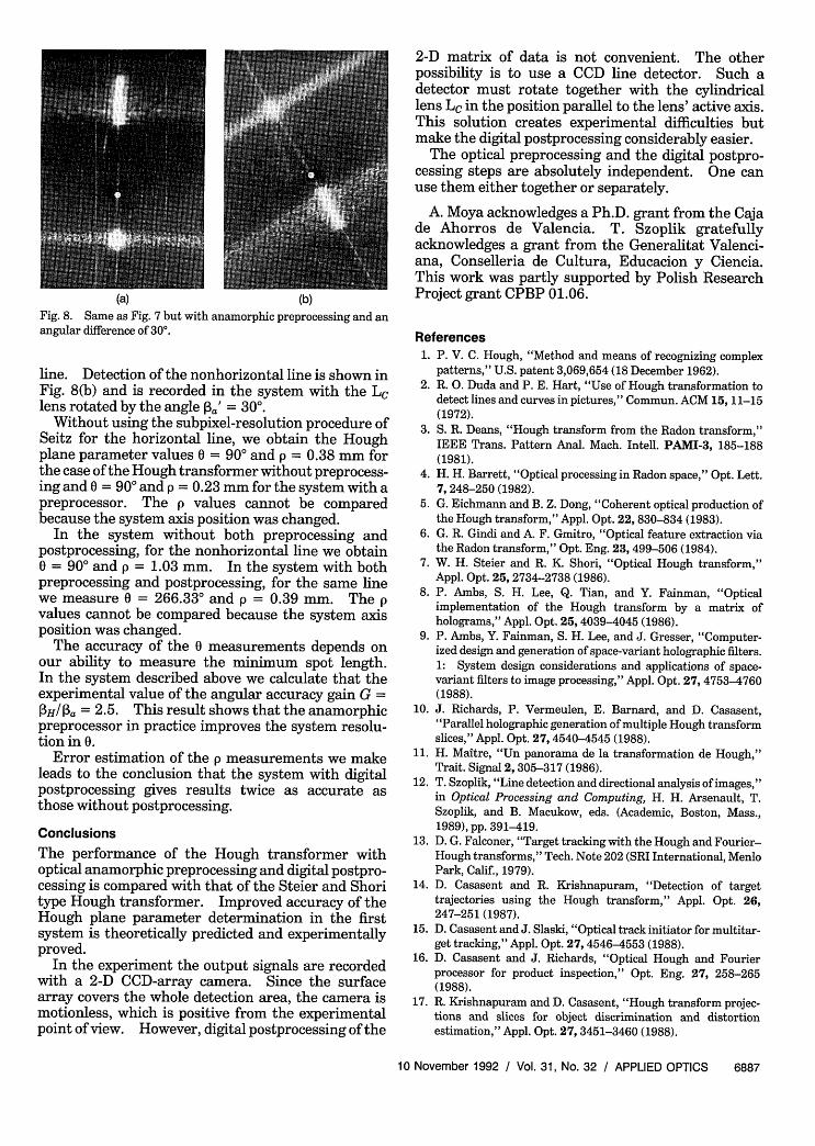
In the Hough transformer with anamorphic prepro-cessing the input object is placed in the x0y0 plane,and Fig. 8 shows output signals recorded in the x9y9plane. Fig. 8(a) shows identification of the horizon-tal line and a smeared spot coming from the inclined
G
aaOM aL 2aM
Fig. 6. Theoretical plot of the factor of angular accuracy gain
G. Its value exceeds unity in the range of angles [0, aL].
(a) (b)
Fig. 7. Output signals recorded in the x9y9 plane of the Houghtransformer without preprocessing. Photographs (a) and (b) showtwo subsequent angular positions of the cylindrical Lc lens, whichdiffer by 2.50. The optical axis is marked in (a) and (b) by whitedots.
(a) (b)Fig. 8. Same as Fig. 7 but with anamorphic preprocessing and anangular difference of 300.
line. Detection of the nonhorizontal line is shown inFig. 8(b) and is recorded in the system with the LClens rotated by the angle pa' = 30'.
Without using the subpixel-resolution procedure ofSeitz for the horizontal line, we obtain the Houghplane parameter values 0 = 900 and p = 0.38 mm forthe case of the Hough transformer without preprocess-ing and 0 = 900 and p = 0.23 mm for the system with apreprocessor. The p values cannot be comparedbecause the system axis position was changed.
In the system without both preprocessing andpostprocessing, for the nonhorizontal line we obtain0 = 900 and p = 1.03 mm. In the system with bothpreprocessing and postprocessing, for the same linewe measure 0 = 266.33° and p = 0.39 mm. The pvalues cannot be compared because the system axisposition was changed.
The accuracy of the 0 measurements depends onour ability to measure the minimum spot length.In the system described above we calculate that theexperimental value of the angular accuracy gain G =
H/a = 2.5. This result shows that the anamorphicpreprocessor in practice improves the system resolu-tion in 0.
Error estimation of the p measurements we makeleads to the conclusion that the system with digitalpostprocessing gives results twice as accurate asthose without postprocessing.
Conclusions
The performance of the Hough transformer withoptical anamorphic preprocessing and digital postpro-cessing is compared with that of the Steier and Shoritype Hough transformer. Improved accuracy of theHough plane parameter determination in the firstsystem is theoretically predicted and experimentallyproved.
In the experiment the output signals are recordedwith a 2-D CCD-array camera. Since the surfacearray covers the whole detection area, the camera ismotionless, which is positive from the experimentalpoint of view. However, digital postprocessing of the
2-D matrix of data is not convenient. The otherpossibility is to use a CCD line detector. Such adetector must rotate together with the cylindricallens LC in the position parallel to the lens' active axis.This solution creates experimental difficulties butmake the digital postprocessing considerably easier.
The optical preprocessing and the digital postpro-cessing steps are absolutely independent. One canuse them either together or separately.
A. Moya acknowledges a Ph.D. grant from the Cajade Ahorros de Valencia. T. Szoplik gratefullyacknowledges a grant from the Generalitat Valenci-ana, Conselleria de Cultura, Educacion y Ciencia.This work was partly supported by Polish ResearchProject grant CPBP 01.06.
References1. P. V. C. Hough, "Method and means of recognizing complex
patterns," U.S. patent 3,069,654 (18 December 1962).2. R. 0. Duda and P. E. Hart, "Use of Hough transformation to
detect lines and curves in pictures," Commun. ACM 15, 11-15(1972).
3. S. R. Deans, "Hough transform from the Radon transform,"IEEE Trans. Pattern Anal. Mach. Intell. PAMI-3, 185-188(1981).
4. H. H. Barrett, "Optical processing in Radon space," Opt. Lett.7, 248-250 (1982).
5. G. Eichmann and B. Z. Dong, "Coherent optical production ofthe Hough transform," Appl. Opt. 22, 830-834 (1983).
6. G. R. Gindi and A. F. Gmitro, "Optical feature extraction viathe Radon transform," Opt. Eng. 23, 499-506 (1984).
7. W. H. Steier and R. K. Shori, "Optical Hough transform,"Appl. Opt. 25, 2734-2738 (1986).
8. P. Ambs, S. H. Lee, Q. Tian, and Y. Fainman, "Opticalimplementation of the Hough transform by a matrix ofholograms," Appl. Opt. 25,4039-4045 (1986).
9. P. Ambs, Y. Fainman, S. H. Lee, and J. Gresser, "Computer-ized design and generation of space-variant holographic filters.1: System design considerations and applications of space-variant filters to image processing," Appl. Opt. 27, 4753-4760(1988).
10. J. Richards, P. Vermeulen, E. Barnard, and D. Casasent,"Parallel holographic generation of multiple Hough transformslices," Appl. Opt. 27, 4540-4545 (1988).
11. H. Maitre, "Un panorama de la transformation de Hough,"Trait. Signal 2, 305-317 (1986).
12. T. Szoplik, "Line detection and directional analysis of images,"in Optical Processing and Computing, H. H. Arsenault, T.Szoplik, and B. Macukow, eds. (Academic, Boston, Mass.,1989), pp. 391-419.
13. D. G. Falconer, "Target tracking with the Hough and Fourier-Hough transforms," Tech. Note 202 (SRI International, MenloPark, Calif., 1979).
14. D. Casasent and R. Krishnapuram, "Detection of targettrajectories using the Hough transform," Appl. Opt. 26,247-251 (1987).
15. D. Casasent and J. Slaski, "Optical track initiator for multitar-get tracking," Appl. Opt. 27, 4546-4553 (1988).
16. D. Casasent and J. Richards, "Optical Hough and Fourierprocessor for product inspection," Opt. Eng. 27, 258-265(1988).
17. R. Krishnapuram and D. Casasent, "Hough transform projec-tions and slices for object discrimination and distortionestimation," Appl. Opt. 27, 3451-3460 (1988).
19. J. Richards and D. P. Casasent, "Extracting input-line posi-tion from Hough transform data," Appl. Opt. 30, 2899-2905(1991).
20. H. Maitre, "Contribution to the prediction of performances ofthe Hough transform," IEEE Trans. Pattern Anal. Mach.Intell. PAMI-8, 669-674 (1986).
21. T. Szoplik and H. H. Arsenault, "Rotation-variant optical data
processing using the 2-D nonsymmetric Fourier transform,"Appl. Opt. 24, 168-172 (1985).
22. P. Seitz, "Optical superresolution using solid-state camerasand digital signal processing," Opt. Eng. 27, 535-540 (1988).
23. T. Szoplik, K. Chalasinska-Macukow, and J. Kosek, "Accuracyof angular spectral analysis with an anamorphic Fouriertransformer," Appl. Opt. 25, 188-192 (1986).
24. C. Vdzquez, C. Ferreira, and T. Szoplik, "Nonlinear angularmagnification of an anamorphic Fourier spectrum," Av-tometriia 6, 53-57 (1989), in Russian.