13
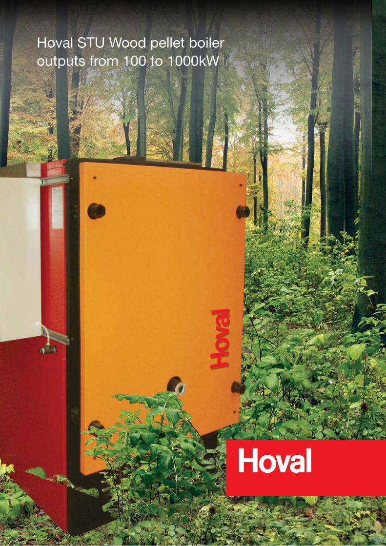
Hoval STU Wood pellet boiler outputs from 100 to 1000kW
Hoval STU Wood pellet boileroutputs from 100 to 1000kW

The Hoval STU Biomass is a welded steel wood - pellet fired LTHW boiler designed and manufactured to fully meet the requirements of EN303-5 Class 3 as tested and verified by TÜV. The boiler comprises of a welded steel shell with a water jacket surrounding an oval combustion chamber and is based on the well-established Hoval ST boiler design, with unique ‘e’ pattern gas flow.
Each STU is supplied with a fully integrated pellet-burning stoker mounted onto the base of the boiler and manufactured from cast steel in heat sensitive areas. This robust combustion system is well proven and has inherently low emissions and a high combustion efficiency.
The boiler has a hinged full front access door, which is lined with heat resistant material and has a sight glass assembly to view the fire bed and combustion chamber.
STU Wood Pellet boilers are offered in outputs from 100 to 1000kW for heating only, the standard version available for operating working pressures of up to 3 bar and temperatures of 90oC.
Design features:
l Combustion chamber layout gives a highly efficient relationship between heating surface and secondary tubes.l Generous combustion design with low heat release rates for added thermal output.l Unique
‚e‘-pattern hot gas flow with refactory and
in-tube spirals designed to deliver an effective three passl Substantial insulation and close-fit casings on all hot surfaces eliminate standing heat losses.l Carbon neutral space and water heatingl Automatic pellet feedl Modulating controlsl Simple flexible layout, the stoker can be mounted at the rear or from the front of the boilerl Listed as an Exempt Appliance under UK Clean Air*l Includes Airless Kindle or Boiler Stand-By function.l Invertor control for motors standard on STU models 600 to 1000. Optional on STU models 150 to 500l Twin cyclone supplied with STU models 800 and 1000.
Optional on STU models 150 - 500
One of the most effective waysto reduce your carbon footprint
* Models 150 - 500kW. (Application for 600/800/1000 pending)
Hoval STUCombines ecology, efficiency and reliability
l Carbon neutral space and water heating
l Wood pellet burning boilers - outputs 100 to 1000kW
l Simple, proven design
l Approved to EN303-5 Class 3
l Modulating controls
l Automatic pellet feed
l Experienced technical support and backup
l Commissioned by Hoval‘s dedicated service team
l Easy maintenance & servicing
l Complimentary plant available
l Designed and Manufactured in the UK by Hoval
Hoval STUCombines ecology, efficiency and reliability
l Carbon neutral space and water heating
l Wood pellet burning boilers - outputs 100 to 1000kW
l Simple, proven design
l Approved to EN303-5 Class 3
l Modulating controls
l Automatic pellet feed
l Experienced technical support and backup
l Commissioned by Hoval‘s dedicated service team
l Easy maintenance & servicing
l Complimentary plant available
l Built in Britain
Hoval STU Wood pellet boileroutputs from 100 to 1000kW
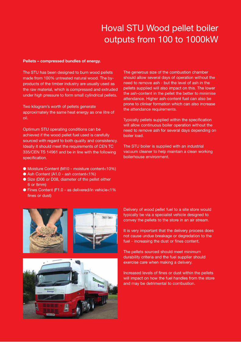
Pellets – compressed bundles of energy.
The STU has been designed to burn wood pellets made from 100% untreated natural wood. The by-products of the timber industry are usually used as the raw material, which is compressed and extruded under high pressure to form small cylindrical pellets.
Two kilogram’s worth of pellets generate approximately the same heat energy as one litre of oil.
Optimum STU operating conditions can be achieved if the wood pellet fuel used is carefully sourced with regard to both quality and consistency. Ideally it should meet the requirements of CEN TC 335/CEN TS 14961 and be in line with the following specification.
l Moisture Content (M10 - moisture content<10%)l Ash Content (A1.0 - ash content<1%)l Size (D06 or D08, diameter of the pellet either 6 or 8mm)l Fines Content (F1.0 - as delivered/in vehicle<1% fines or dust)
The generous size of the combustion chamber should allow several days of operation without the need to remove ash - but the level of ash in the pellets supplied will also impact on this. The lower the ash-content in the pellet the better to minimise attendance. Higher ash-content fuel can also be prone to clinker formation which can also increase the attendance requirements.
Typically pellets supplied within the specification will allow continuous boiler operation without the need to remove ash for several days depending on boiler load.
The STU boiler is supplied with an industrial vacuum cleaner to help maintain a clean working boilerhouse environment.
Delivery of wood pellet fuel to a site store would typically be via a specialist vehicle designed to convey the pellets to the store in an air stream.
It is very important that the delivery process does not cause undue breakage or degredation to the fuel - increasing the dust or fines content.
The pellets sourced should meet minimum durability criteria and the fuel supplier should exercise care when making a delivery.
Increased levels of fines or dust within the pellets will impact on how the fuel handles from the store and may be detrimental to combustion.
Hoval STU
Technical Data
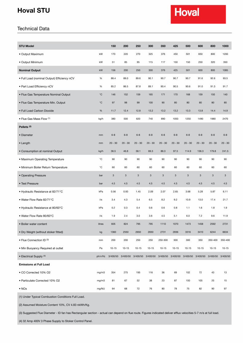
STU Model 150 200 250 300 350 425 500 600 800 1000
• Output Maximum kW 170 220 270 325 376 450 501 650 800 1200
• Output Minimum kW 51 85 95 115 117 150 150 250 320 350
Nominal Output kW 156 200 250 300 376 425 501 600 800 1085
• Full Load (nominal Output) Efficiency nCV % 88.4 89.0 89.6 90.1 90.7 90.7 90.7 91.6 92.6 93.5
• Part Load Efficiency nCV % 85.2 86.5 87.8 89.1 90.4 90.5 90.6 91.0 91.3 91.7
• Flue Gas Temperature Nominal Output °C 146 152 159 165 171 170 168 159 150 140
• Flue Gas Temperature Min. Output °C 97 98 99 100 90 80 80 80 80 80
• Full Load Carbon Dioxide % 11.7 12.4 12.8 13.2 13.2 13.2 13.3 13.8 14.4 14.9
• Flue Gas Mass Flow (1) kg/h 380 500 620 740 890 1050 1250 1490 1980 2470
Pellets (2)
• Diameter mm 6-8 6-8 6-8 6-8 6-8 6-8 6-8 6-8 6-8 6-8
• Length mm 20 - 30 20 - 30 20 - 30 20 - 30 20 - 30 20 - 30 20 - 30 20 - 30 20 - 30 20 - 30
• Consumption at nominal Output kg/h 36.5 46.8 58.1 69.3 86.3 97.5 114.9 136.3 179.8 241.5
• Maximum Operating Temperature °C 90 90 90 90 90 90 90 90 90 90
• Minimum Boiler Return Temperature °C 60 60 60 60 60 60 60 60 60 60
• Operating Pressure bar 3 3 3 3 3 3 3 3 3 3
• Test Pressure bar 4.5 4.5 4.5 4.5 4.5 4.5 4.5 4.5 4.5 4.5
• Hydraulic Resistance at 82/71°C kPa 0.56 0.93 1.45 2.09 2.07 2.65 3.68 5.28 5.87 6.11
• Water Flow Rate 82/71°C l/s 3.4 4.3 5.4 6.5 8.2 9.2 10.9 13.0 17.4 21.7
• Hydraulic Resistance at 80/60°C kPa 0.2 0.3 0.4 0.6 0.6 0.8 1.1 1.6 1.8 1.9
• Water Flow Rate 80/60°C l/s 1.9 2.4 3.0 3.6 4.5 5.1 6.0 7.2 9.6 11.9
• Boiler water content litres 605 824 795 795 1110 1070 1473 1458 2592 2731
• Dry Weight (without stoker fitted) kg 1360 2550 2650 2650 2731 2836 3316 3410 6244 6634
• Flue Connection ID (3) mm 200 200 250 250 250-300 300 300 350 350-400 350-400
• Min Buoyancy Required at outlet Pa 10-15 10-15 10-15 10-15 10-15 10-15 10-15 10-15 10-15 10-15
• Electrical Supply (4) ph/v/Hz 3/400/50 3/400/50 3/400/50 3/400/50 3/400/50 3/400/50 3/400/50 3/400/50 3/400/50 3/400/50
Emissions at Full Load
• CO Corrected 10% O2 mg/m3 354 275 195 116 36 69 102 72 43 13
• Particulate Corrected 10% O2 mg/m3 81 67 52 38 23 87 150 105 25 15
• NOx mg/MJ 64 68 72 76 80 78 75 82 90 97
(1) Under Typical Combustion Conditions Full Load.
(2) Assumed Moisture Content 10%, CV 4.83 nkWh/Kg.
(3) Suggested Flue Diameter - ID fan has Rectangular section - actual can depend on flue route. Figures indicated deliver efflux velocities 5-7 m/s at full load.
(4) 32 Amp 400V 3 Phase Supply to Stoker Control Panel.
Hoval STU
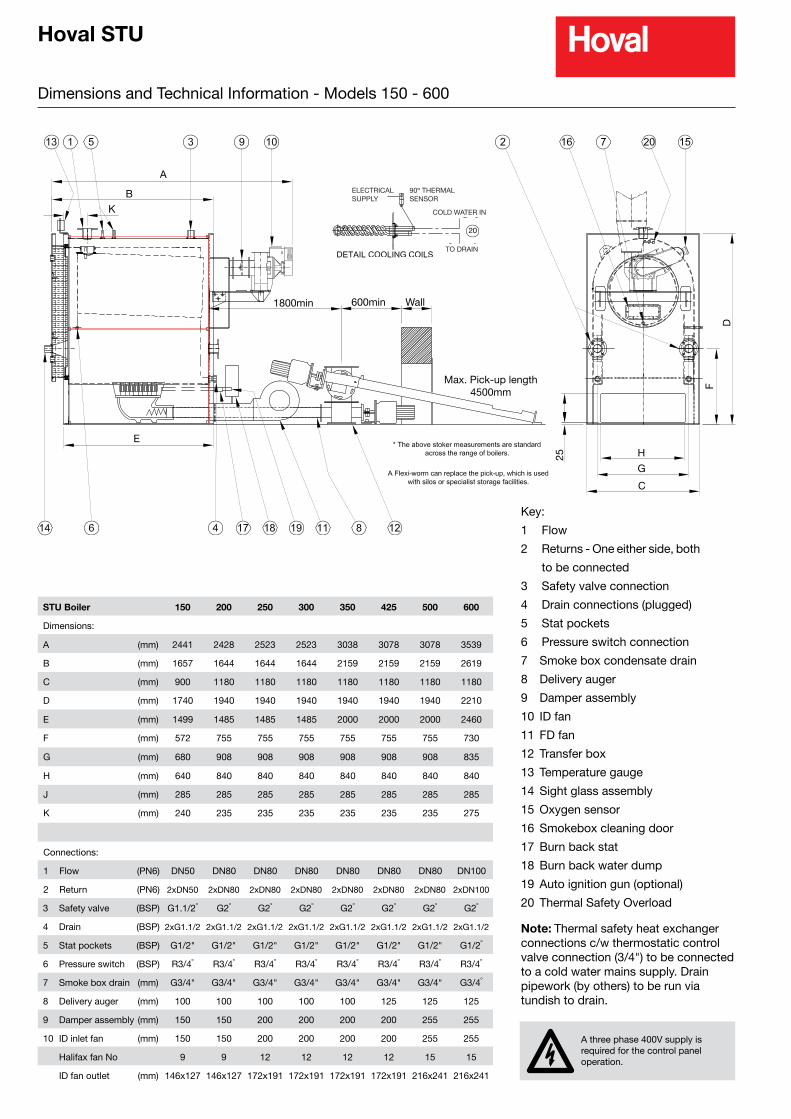
Dimensions and Technical Information - Models 150 - 600
A
B
K
E
1800min 600min Wall
Max. Pick-up length4500mm
F
D
H
G
C
25
STU Boiler 150 200 250 300 350 425 500 600
Dimensions:
A (mm) 2441 2428 2523 2523 3038 3078 3078 3539
B (mm) 1657 1644 1644 1644 2159 2159 2159 2619
C (mm) 900 1180 1180 1180 1180 1180 1180 1180
D (mm) 1740 1940 1940 1940 1940 1940 1940 2210
E (mm) 1499 1485 1485 1485 2000 2000 2000 2460
F (mm) 572 755 755 755 755 755 755 730
G (mm) 680 908 908 908 908 908 908 835
H (mm) 640 840 840 840 840 840 840 840
J (mm) 285 285 285 285 285 285 285 285
K (mm) 240 235 235 235 235 235 235 275
Connections:
1 Flow (PN6) DN50 DN80 DN80 DN80 DN80 DN80 DN80 DN100
2 Return (PN6) 2xDN50 2xDN80 2xDN80 2xDN80 2xDN80 2xDN80 2xDN80 2xDN100
3 Safety valve (BSP) G1.1/2º G2º G2º G2º G2º G2º G2º G2º
4 Drain (BSP) 2xG1.1/2 2xG1.1/2 2xG1.1/2 2xG1.1/2 2xG1.1/2 2xG1.1/2 2xG1.1/2 2xG1.1/2
5 Stat pockets (BSP) G1/2" G1/2" G1/2" G1/2" G1/2" G1/2" G1/2" G1/2º
6 Pressure switch (BSP) R3/4º R3/4º R3/4º R3/4º R3/4º R3/4º R3/4º R3/4º
7 Smoke box drain (mm) G3/4" G3/4" G3/4" G3/4" G3/4" G3/4" G3/4" G3/4º
8 Delivery auger (mm) 100 100 100 100 100 125 125 125
9 Damper assembly (mm) 150 150 200 200 200 200 255 255
10 ID inlet fan (mm) 150 150 200 200 200 200 255 255
Halifax fan No 9 9 12 12 12 12 15 15
ID fan outlet (mm) 146x127 146x127 172x191 172x191 172x191 172x191 216x241 216x241
Key:
1 Flow
2 Returns - One either side, both
to be connected
3 Safety valve connection
4 Drain connections (plugged)
5 Stat pockets
6 Pressure switch connection
7 Smoke box condensate drain
8 Delivery auger
9 Damper assembly
10 ID fan
11 FD fan
12 Transfer box
13 Temperature gauge
14 Sight glass assembly
15 Oxygen sensor
16 Smokebox cleaning door
17 Burn back stat
18 Burn back water dump
19 Auto ignition gun (optional)
20 Thermal Safety Overload
A three phase 400V supply is required for the control panel operation.
Note: Thermal safety heat exchanger connections c/w thermostatic control valve connection (3/4") to be connected to a cold water mains supply. Drain pipework (by others) to be run via tundish to drain.
ELECTRICALSUPPLY
90º THERMALSENSOR
COLD WATER IN
TO DRAIN
20
Hoval STU
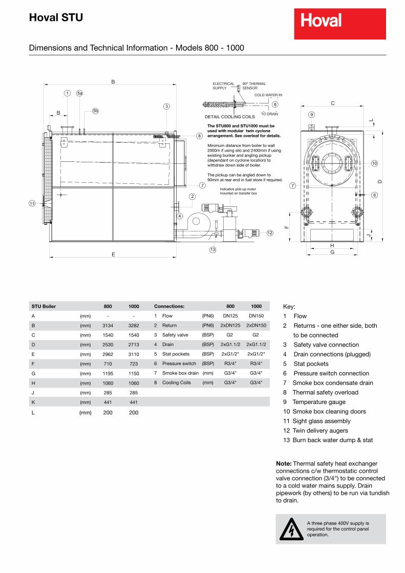
Dimensions and Technical Information - Models 800 - 1000
B
E
C
L
D
HG
J
F
B
ELECTRICALSUPPLY
90º THERMALSENSOR
COLD WATER IN
TO DRAIN
Key:
1 Flow
2 Returns - one either side, both
to be connected
3 Safety valve connection
4 Drain connections (plugged)
5 Stat pockets
6 Pressure switch connection
7 Smoke box condensate drain
8 Thermal safety overload
9 Temperature gauge
10 Smoke box cleaning doors
11 Sight glass assembly
12 Twin delivery augers
13 Burn back water dump & stat
Note: Thermal safety heat exchanger connections c/w thermostatic control valve connection (3/4") to be connected to a cold water mains supply. Drain pipework (by others) to be run via tundish to drain.
Connections: 800 1000
1 Flow (PN6) DN125 DN150
2 Return (PN6) 2xDN125 2xDN150
3 Safety valve (BSP) G2ײ G2ײ
4 Drain (BSP) 2xG1.1/2 2xG1.1/2
5 Stat pockets (BSP) 2xG1/2" 2xG1/2"
6 Pressure switch (BSP) R3/4" R3/4"
7 Smoke box drain (mm) G3/4" G3/4"
8 Cooling Coils (mm) G3/4" G3/4"
STU Boiler 800 1000
A (mm) - -
B (mm) 3134 3282
C (mm) 1540 1540
D (mm) 2530 2713
E (mm) 2962 3110
F (mm) 710 723
G (mm) 1195 1150
H (mm) 1060 1060
J (mm) 285 285
K (mm) 441 441
L (mm) 200 200
A three phase 400V supply is required for the control panel operation.
The STU800 and STU1000 must be used with modular twin cyclone arrangement. See overleaf for details.
Minimum distance from boiler to wall 2000m if using silo and 2400mm if using existing bunker and angling pickup (dependant on cyclone location) to withdraw down side of boiler.
The pickup can be angled down to 90mm at rear end in fuel store if required.
Hoval STU
Dimensions and Technical Information
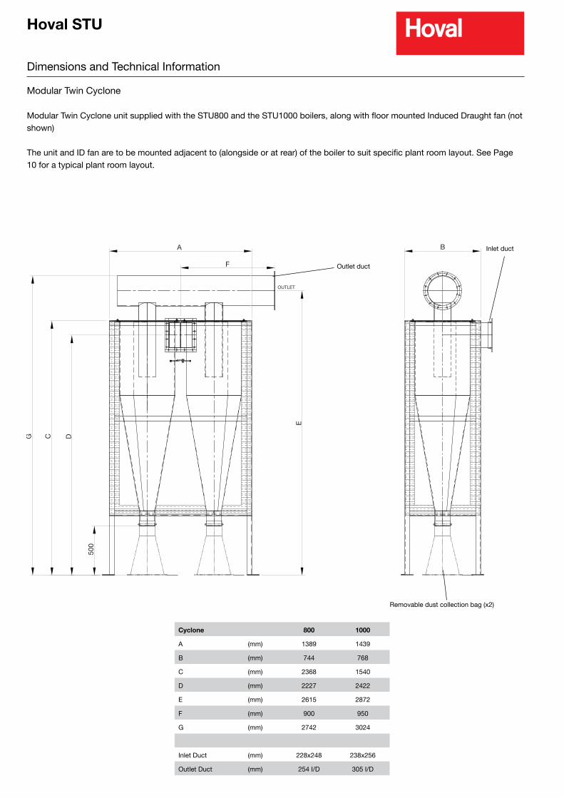
Modular Twin Cyclone
Modular Twin Cyclone unit supplied with the STU800 and the STU1000 boilers, along with floor mounted Induced Draught fan (not shown)
The unit and ID fan are to be mounted adjacent to (alongside or at rear) of the boiler to suit specific plant room layout. See Page 10 for a typical plant room layout.
A
F
OUTLET
E
DCG
500
B
Cyclone 800 1000
A (mm) 1389 1439
B (mm) 744 768
C (mm) 2368 1540
D (mm) 2227 2422
E (mm) 2615 2872
F (mm) 900 950
G (mm) 2742 3024
Inlet Duct (mm) 228x248 238x256
Outlet Duct (mm) 254 I/D 305 I/D
Outlet duct
Inlet duct
Removable dust collection bag (x2)
Hoval STU
Dimensions and Technical Information
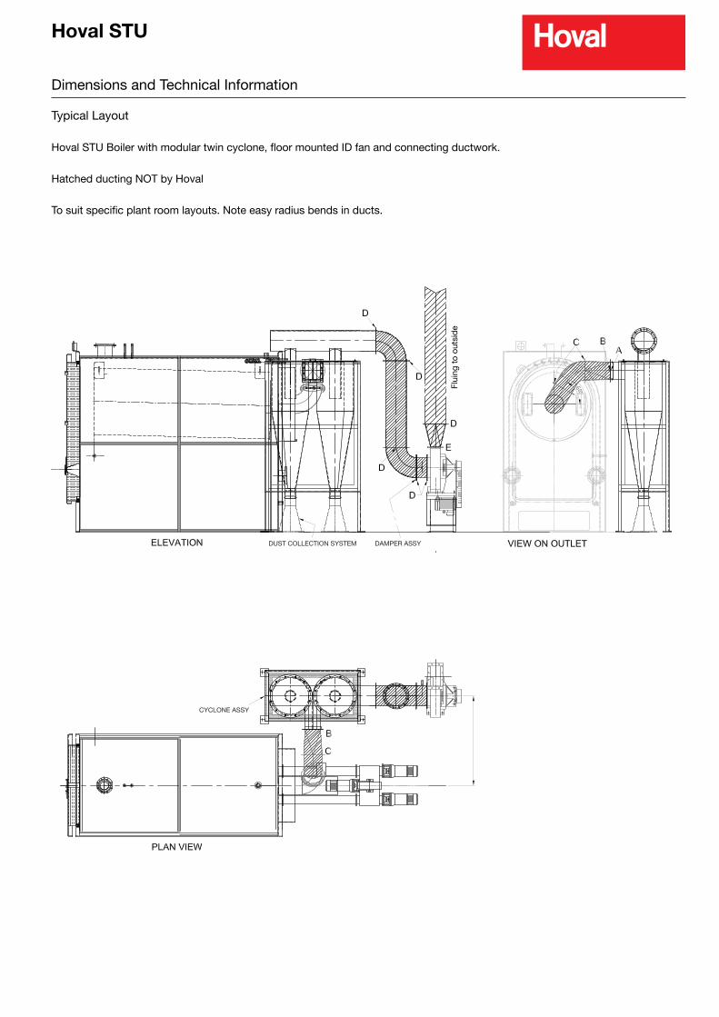
Typical Layout
Hoval STU Boiler with modular twin cyclone, floor mounted ID fan and connecting ductwork.
Hatched ducting NOT by Hoval
To suit specific plant room layouts. Note easy radius bends in ducts.
DUST COLLECTION SYSTEM DAMPER ASSY
CYCLONE ASSY
DUST COLLECTION SYSTEM DAMPER ASSY
CYCLONE ASSY
Flui
ng t
o ou
tsid
e
Hoval STU
Plantroom Layout
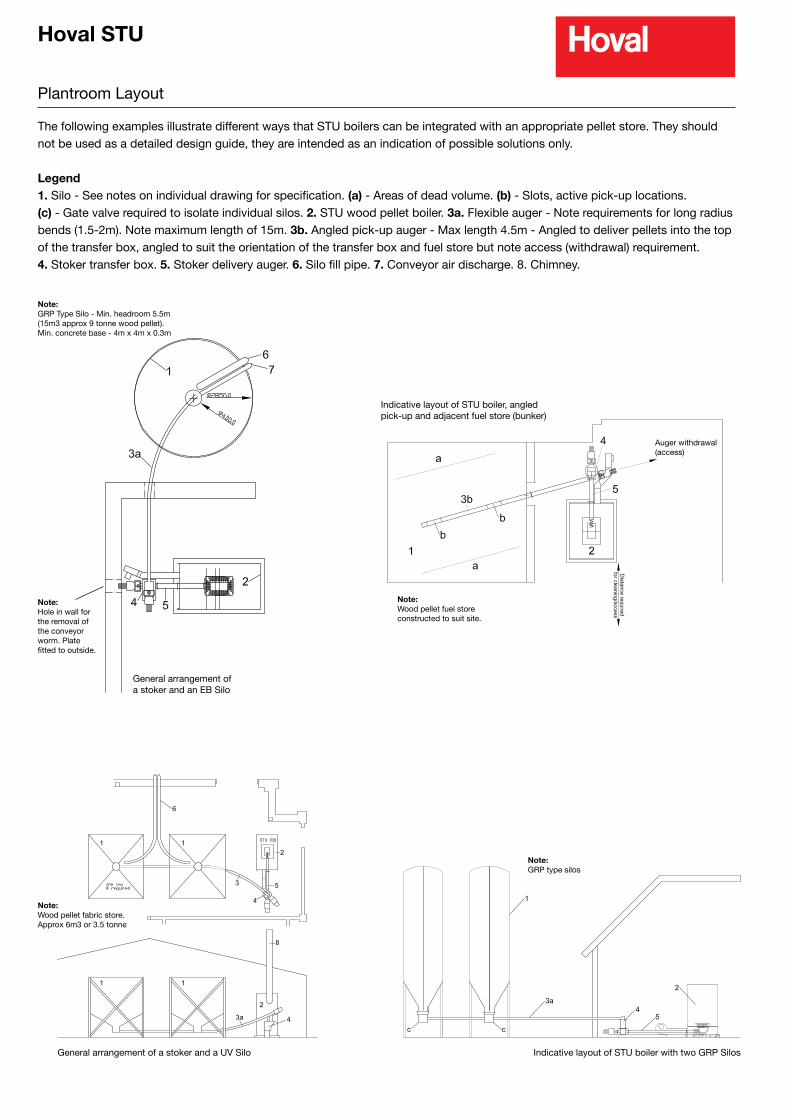
The following examples illustrate different ways that STU boilers can be integrated with an appropriate pellet store. They should not be used as a detailed design guide, they are intended as an indication of possible solutions only.
Legend1. Silo - See notes on individual drawing for specification. (a) - Areas of dead volume. (b) - Slots, active pick-up locations. (c) - Gate valve required to isolate individual silos. 2. STU wood pellet boiler. 3a. Flexible auger - Note requirements for long radius bends (1.5-2m). Note maximum length of 15m. 3b. Angled pick-up auger - Max length 4.5m - Angled to deliver pellets into the top of the transfer box, angled to suit the orientation of the transfer box and fuel store but note access (withdrawal) requirement.4. Stoker transfer box. 5. Stoker delivery auger. 6. Silo fill pipe. 7. Conveyor air discharge. 8. Chimney.
Note:GRP Type Silo - Min. headroom 5.5m(15m3 approx 9 tonne wood pellet).Min. concrete base - 4m x 4m x 0.3m
General arrangement of a stoker and an EB Silo
Note:Hole in wall for the removal of the conveyor worm. Plate fitted to outside.
General arrangement of a stoker and a UV Silo
Note:Wood pellet fabric store.Approx 6m3 or 3.5 tonne
Note:Wood pellet fuel store constructed to suit site.
Indicative layout of STU boiler, angled pick-up and adjacent fuel store (bunker)
Auger withdrawal(access)
Note:GRP type silos
Indicative layout of STU boiler with two GRP Silos
Hoval STU
Design Guidelines
General
Boiler OutputMatching to Anticipated Load
Establishing the likely required load is the first step in selecting the most appropriate Hoval Biomass Wood Pellet Boiler.
All Hoval Wood Pellet Boilers are fitted with modulating combustion systems that allow some turn down, however optimum combustion conditions are achieved when the boilers are allowed to fire as continuously as possible.
Therefore care should be exercised in selecting the most appropriately sized wood pellet boiler (or combinations of boilers) to match the anticipated load.
Consideration should be given to the seasonal variation in the likely load.
Fuel Storage
A bulk wood pellet fuel store should be included in the system design, which should be located as close as possible to the biomass boiler(s).
The design of the fuel store and the recovery of the pellets from the store and the subsequent transfer of the fuel to the boiler is generally the critical part of the Biomass system design.
Ideally the store and transfer of fuel should be kept as simple and most straightforward as possible. Tall thin storage – such as purpose design silo’s – often represent the most effective way of storing wood pellet fuel and can lead to the best use of a given storage volume. The angle of the discharge cone from such a silo would typically be 60º to ensure complete mass flow from the store.
A possible alternative to a storage silo would be a bespoke built bunker store. These typically require a larger floor area and are less effective in terms of the available recoverable volume of fuel. Some profiling of the bunker base should be considered – minimum angles of 45º should be adopted if profiling bunker – which will significantly reduce the volume available for the storage of pellet
fuel. The design of a bespoke bunker should be such to avoid ‘dead volume’
The natural angle of repose of the fuel will vary depending on the quality of the wood pellet (see below) but will typically be greater than 45º. Again this can significantly reduce the recoverable volume available in the pellet store.
Whichever fuel store design is adopted it must be such that it:
l Keeps the fuel dry – water ingress will cause the pellets to fall apart and block handling equipment.l Is located as close as possible to the boiler.l Has adequate vehicle access – to allow easy bulk delivery.l Is fitted with appropriately sized delivery pipe work l Bulk fuel deliveries would normally blow fuel into store via pipe. l Delivery pipe work/bunker design should not cause undue fuel breakage during delivery.l Is sealed to prevent possible dust nuisance l Conveying air used for fuel delivery needs to be filtered prior to discharge.l Is sized to suit boiler load and likely bulk delivery payload.l May need to be behind a fire rated wall if inside plant room (consult local Building Control).
Fuel Store Sizing
There are 3 key factors that influence the size of the pellet store.
1. Available Space – usually adjacent to or close to boilers – taking account of best use of that space.2. Estimated Fuel consumption.3. The required frequency of delivery – or the size of delivery anticipated.
For Design purposes the following can be used as indicative
1. Bulk density or Volume ofWood Pellet Fuel. a. Good quality wood pellet fuel will typically have a bulk density of 600kg/m3
b. Angle of repose of good quality fuel approx 50 – 55 º - which
impacts on recoverable volume in bunker.2. Fuel Consumption. a. As an indication the maximum fuel consumption (kg/hr) would be 0.23 x Max Output of the Biomass boiler (kW). b. Actual fuel consumption would be estimated based on the loading placed on the boiler. c. Wood Pellet fuel store to be sized to accommodate a minimum of 10 – 15 days anticipated fuel use. 3. Delivery Size. a. The fuel supplier will have preferred bulk delivery sizes – based on payload of vehicle employed. b. Store should be sized to accommodate minimum delivery size. c. First Fill delivery could be larger than subsequent deliveries, accounting for possible dead volume within the store and making allowance for small working stock needed while waiting for a delivery.
Hoval can offer a number of silo based fuel store options or advise on most appropriate use of available space for a bespoke build fuel store.
Automatic Fuel Wood Pellet Transfer
Provision needs to be made for the recovery of the wood pellet fuel from the bulk store and subsequent transfer to the boiler.
The exact nature of the transfer system depends on the fuel store, the boiler model selected and the site layout. However it would typically include an auger - either a conventional centred auger with flights, or the flexible centreless type – and adequate access should be allowed to maintain such items. Typical examples can be found with the previous section.
It is vital that there is always sufficient pellets within the store – taking account of any possible dead volume - to ensure that pick-up or flexible augers are always covered with fuel.
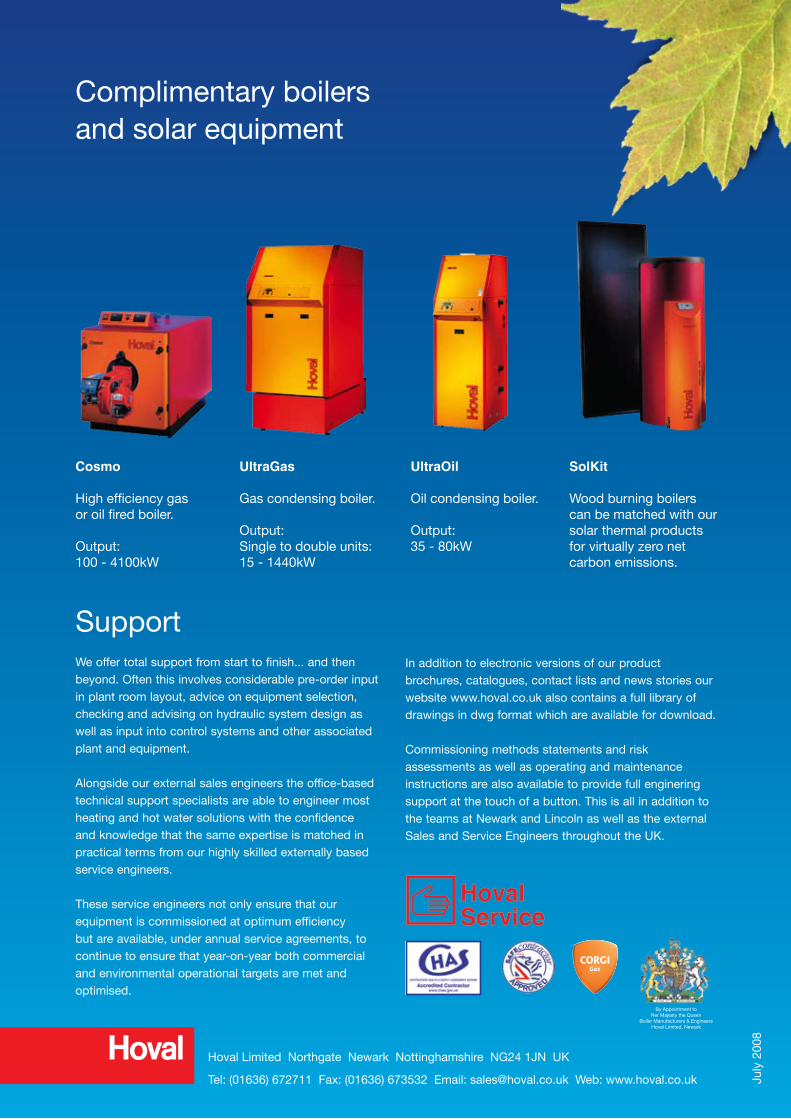
Complimentary boilersand solar equipment
Hoval Limited Northgate Newark Nottinghamshire NG24 1JN UK
Tel: (01636) 672711 Fax: (01636) 673532 Email: [email protected] Web: www.hoval.co.uk July
200
8
Cosmo
High efficiency gasor oil fired boiler.
Output:100 - 4100kW
UltraGas
Gas condensing boiler.
Output:Single to double units:15 - 1440kW
UltraOil
Oil condensing boiler.
Output:35 - 80kW
SolKit
Wood burning boilers can be matched with our solar thermal products for virtually zero net carbon emissions.
SupportWe offer total support from start to finish... and then beyond. Often this involves considerable pre-order input in plant room layout, advice on equipment selection, checking and advising on hydraulic system design as well as input into control systems and other associated plant and equipment.
Alongside our external sales engineers the office-based technical support specialists are able to engineer most heating and hot water solutions with the confidence and knowledge that the same expertise is matched in practical terms from our highly skilled externally based service engineers.
These service engineers not only ensure that our equipment is commissioned at optimum efficiency but are available, under annual service agreements, to continue to ensure that year-on-year both commercial and environmental operational targets are met and optimised.
In addition to electronic versions of our product brochures, catalogues, contact lists and news stories our website www.hoval.co.uk also contains a full library of drawings in dwg format which are available for download.
Commissioning methods statements and risk assessments as well as operating and maintenance instructions are also available to provide full enginering support at the touch of a button. This is all in addition to the teams at Newark and Lincoln as well as the external Sales and Service Engineers throughout the UK.
By Appointment toHer Majesty the Queen
Boiler Manufacturers & EngineersHoval Limited, Newark


![Solar [ExA-en] 2016 - Hoval€¦ · T P Hoval solar armature groups Description55 Part No. 56 Technical data 62 Dimensions65 Solar controllers and accessories Solar systems Hoval](https://static.documents.pub/doc/80x56/6076d7ed067e986d61693486/solar-exa-en-2016-hoval-t-p-hoval-solar-armature-groups-description55-part-no.jpg)


