17
A Tutorial RC Hovercraft
| Date post: | 04-Jun-2018 |
| Category: |
Documents |
| Upload: | bharath-kumar |
| View: | 224 times |
| Download: | 0 times |
8/13/2019 Hover on Tut
http://slidepdf.com/reader/full/hover-on-tut 1/17
A Tutorial
RC Hovercraft

8/13/2019 Hover on Tut
http://slidepdf.com/reader/full/hover-on-tut 2/17
Contents
Introduction
Forces
Manoeuvring
Requisite material Electronics
Transmission
Placement of components Drifting and Rotation
Frequently faced problems
8/13/2019 Hover on Tut
http://slidepdf.com/reader/full/hover-on-tut 3/17
Introduction
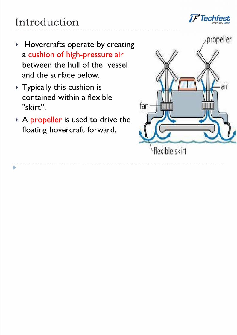
Hovercrafts operate by creatinga cushion of high-pressure air
between the hull of the vessel
and the surface below.
Typically this cushion is
contained within a flexible
"skirt”.
A propeller is used to drive thefloating hovercraft forward.

8/13/2019 Hover on Tut
http://slidepdf.com/reader/full/hover-on-tut 4/17
Major components
8/13/2019 Hover on Tut
http://slidepdf.com/reader/full/hover-on-tut 5/17
Forces on a hovercraft
LIFT: The lift motor provides the force which balances
the weight of the hovercraft.
THRUST: The drive motor provides the force which
drives the hovercraft forward.Lift and thrust can be integrated and produced through a
single motor.
These forces can be provided by
-Standard RC Brushless Motors
-Duct-fans
8/13/2019 Hover on Tut
http://slidepdf.com/reader/full/hover-on-tut 6/17
Manoeuvring
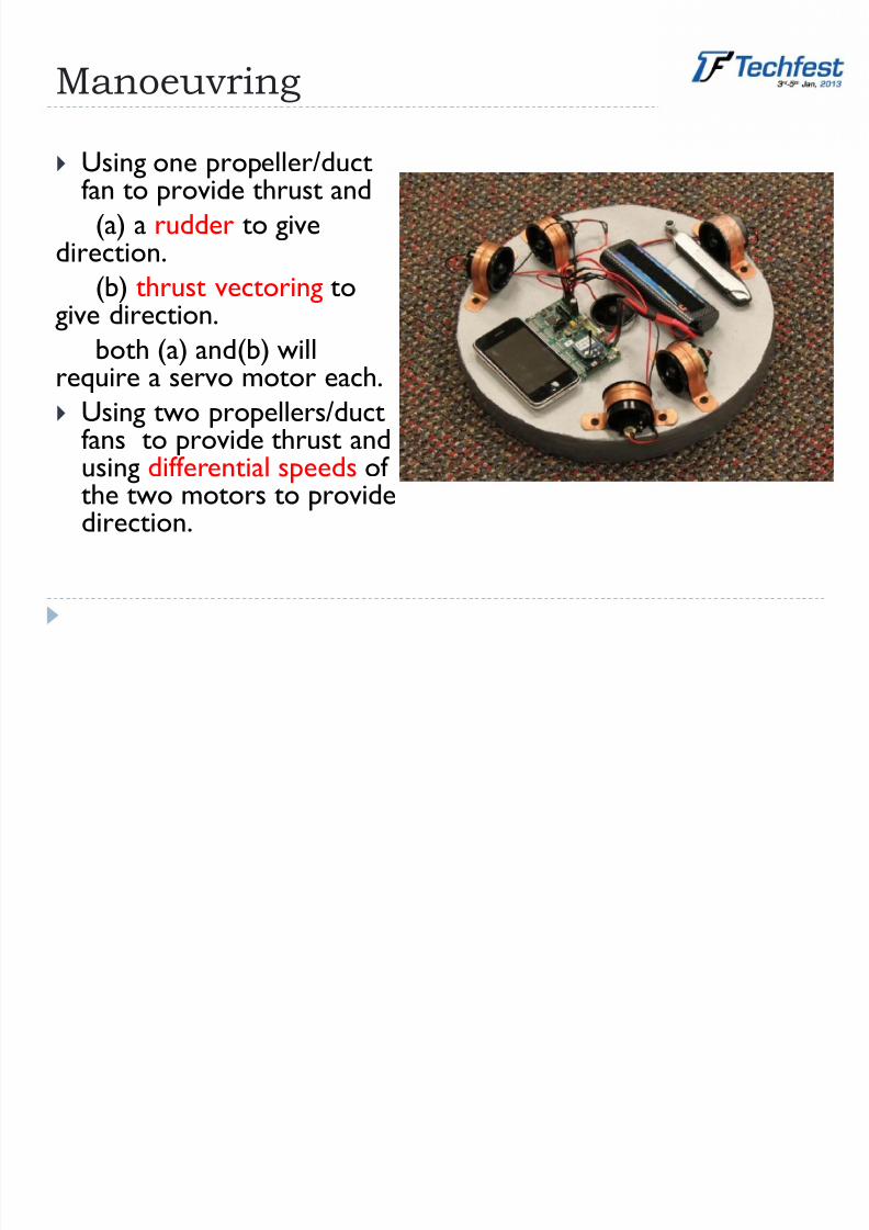
Using one propeller/ductfan to provide thrust and
(a) a rudder to givedirection.
(b) thrust vectoring togive direction.
both (a) and(b) willrequire a servo motor each.
Using two propellers/duct
fans to provide thrust andusing differential speeds ofthe two motors to providedirection.

8/13/2019 Hover on Tut
http://slidepdf.com/reader/full/hover-on-tut 7/17
Requisite material
Balsa wood/Coroplast/Styrofoam –
main structure, rudders, duct
Styrofoam – skirt boundaries, duct
Wood – motor mount, rudderstructure, strengthening
Adhesives – Standard epoxies,
Bond Tite, Bond Quick, Tape
A thin inflatable polythenematerial – Hovercraft skirt

8/13/2019 Hover on Tut
http://slidepdf.com/reader/full/hover-on-tut 8/17
Electronics: Battery
Lithium Polymer (LiPo) Batteries are by far the most longlasting batteries used for RC applications. Deliver twice
the capacity in nearly half the weight of conventional cells.
Cost and Weight: More the current and voltage rating and
capacity, more is the cost and weight.
Example:
Minimum Capacity: 1000mAh
Configuration: 3S1P / 11.1v / 3Cell Constant Discharge: 20C
Peak Discharge (10sec): 30C
Pack Weight: 87g

8/13/2019 Hover on Tut
http://slidepdf.com/reader/full/hover-on-tut 9/17
Electronics: Servo
Voltage : 3v ~ 6v
Weight: 9gSpeed : 0.12
sec/60(4.8V)
Torque : 1.6 kg-cm
8/13/2019 Hover on Tut
http://slidepdf.com/reader/full/hover-on-tut 10/17
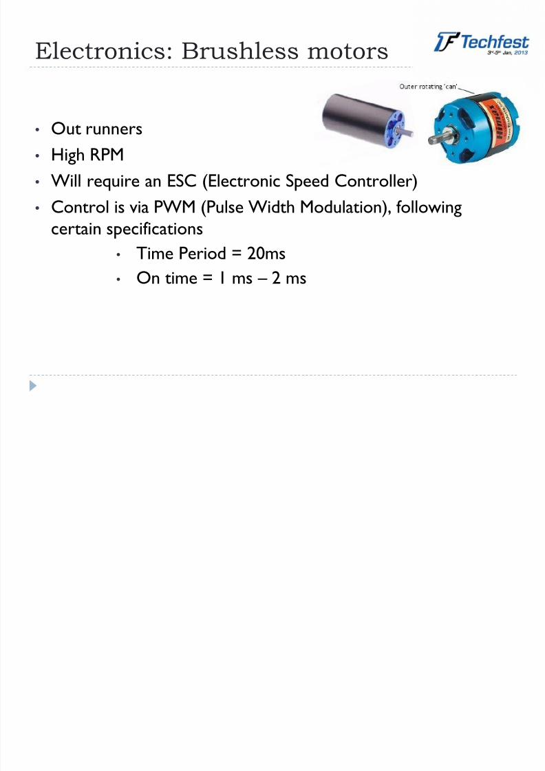
Electronics: Brushless motors
• Out runners
• High RPM
•
Will require an ESC (Electronic Speed Controller)• Control is via PWM (Pulse Width Modulation), following
certain specifications
• Time Period = 20ms
•
On time = 1 ms –
2 ms
8/13/2019 Hover on Tut
http://slidepdf.com/reader/full/hover-on-tut 11/17
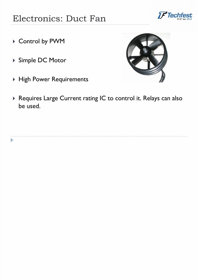
Electronics: Duct Fan
Control by PWM
Simple DC Motor
High Power Requirements
Requires Large Current rating IC to control it. Relays can also
be used.
8/13/2019 Hover on Tut
http://slidepdf.com/reader/full/hover-on-tut 12/17
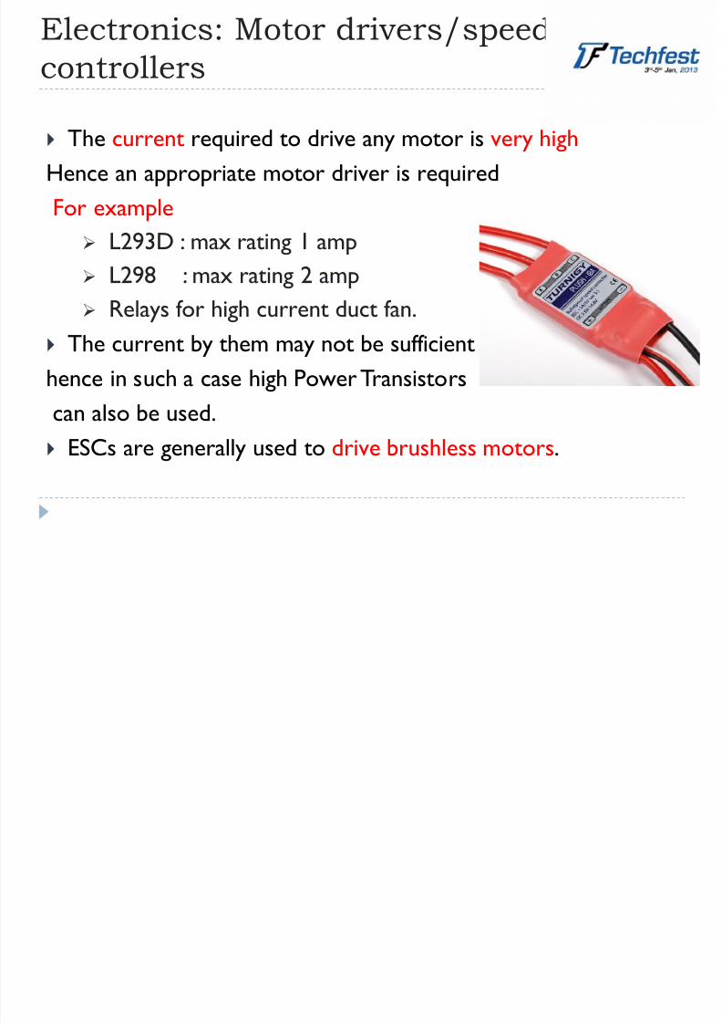
Electronics: Motor drivers/speed
controllers
The current required to drive any motor is very high
Hence an appropriate motor driver is required
For example
L293D : max rating 1 amp L298 : max rating 2 amp
Relays for high current duct fan.
The current by them may not be sufficient
hence in such a case high Power Transistorscan also be used.
ESCs are generally used to drive brushless motors.
8/13/2019 Hover on Tut
http://slidepdf.com/reader/full/hover-on-tut 13/17
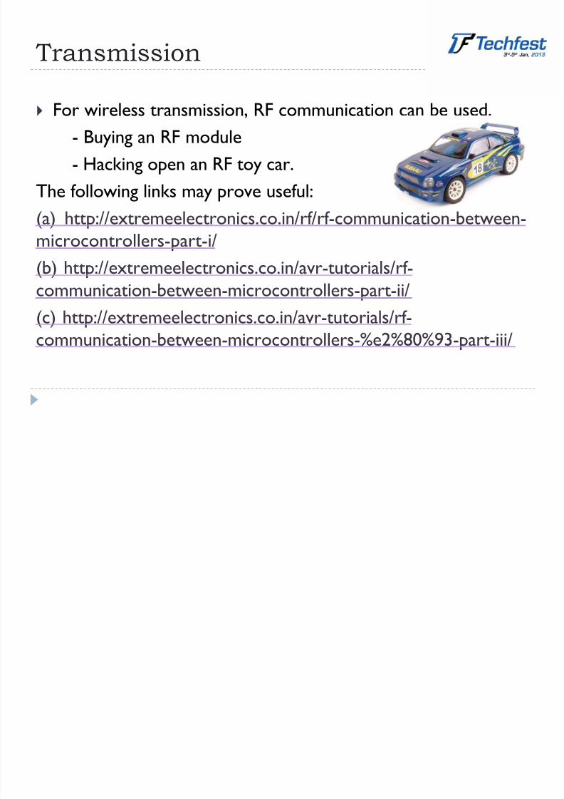
Transmission
For wireless transmission, RF communication can be used.
- Buying an RF module
- Hacking open an RF toy car.
The following links may prove useful:(a) http://extremeelectronics.co.in/rf/rf-communication-between-
microcontrollers-part-i/
(b) http://extremeelectronics.co.in/avr-tutorials/rf-
communication-between-microcontrollers-part-ii/ (c) http://extremeelectronics.co.in/avr-tutorials/rf-
communication-between-microcontrollers-%e2%80%93-part-iii/

8/13/2019 Hover on Tut
http://slidepdf.com/reader/full/hover-on-tut 14/17
Placement of components
Placement of the componentsdecides the CG of the vehicle
The CG should be perfectlyaligned with the Thrust line
Since the system is afloat it willexperience some rogue torquecaused by this misalignment ofcomponents
Too many actuators may alsoprovide torque and add to theinstability

8/13/2019 Hover on Tut
http://slidepdf.com/reader/full/hover-on-tut 15/17
Drifting and Rotation
The hovercraft system suffers fromthe inherent problem of drifting.
This requires a flawless mechanicaldesign.
A good electronic system may notbe able to counter all theseglitches.
Rotation can however be regulated
by an effective control system Rotation is caused due to the
principle of conservation ofangular momentum

8/13/2019 Hover on Tut
http://slidepdf.com/reader/full/hover-on-tut 16/17
Frequently faced problems
Please keep the following aspects in
mind :-
Hovercraft tends to drift outward
at curves.
Natural tendency of the hovercraft
is to drift and rotate.
Sufficient momentum might be
required to climb up a slope which
is an obstacle in the finale.
At the U-turn towards the end ofthe arena, the hovercraft may tend
to turn in one direction
preferentially because of the
angular momentum of the lift fan.

8/13/2019 Hover on Tut
http://slidepdf.com/reader/full/hover-on-tut 17/17


