60
HOW A JET ENGINE WORKS 15/02/2019 Prepared by Guy E Davies CEng FIMechE 1 Photo © Guy E Davies

HOW A JET ENGINE WORKS
15/02/2019 Prepared by Guy E Davies CEng FIMechE 1
Photo © Guy E Davies
How a Jet Engine Works
• Basic Concept
• Compressor
• Combustion Chamber
• Turbine
• Jet Pipe
• Fan
• Operating Conditions
• Fuel Control
15/02/2019 Prepared by Guy E Davies CEng FIMechE 2

Basic Concept
15/02/2019 Prepared by Guy E Davies CEng FIMechE 3
There are two questions to answer about how a jet engine works
1) How does it work internally?2) How does it generate thrust?
Before we go into details, let’s just look at the basic concept:
16/02/2019 Prepared by Guy E Davies CEng FIMechE 4
Basic Concept
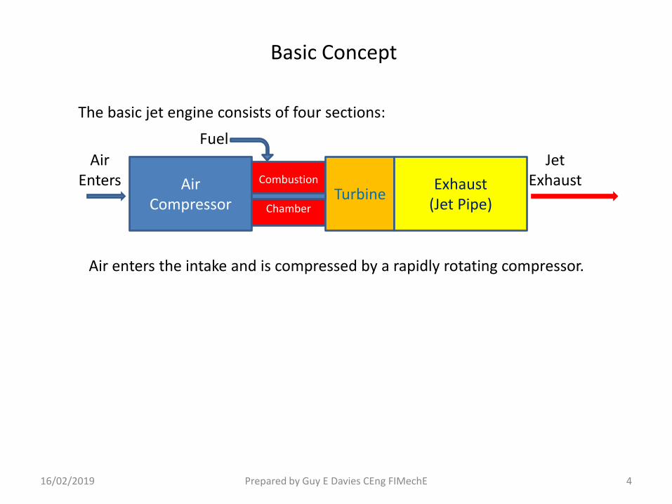
The basic jet engine consists of four sections:
Air enters the intake and is compressed by a rapidly rotating compressor.
AirCompressor
Combustion
ChamberTurbine
Exhaust(Jet Pipe)
AirEnters
JetExhaust
Fuel
16/02/2019 Prepared by Guy E Davies CEng FIMechE 5
Basic Concept
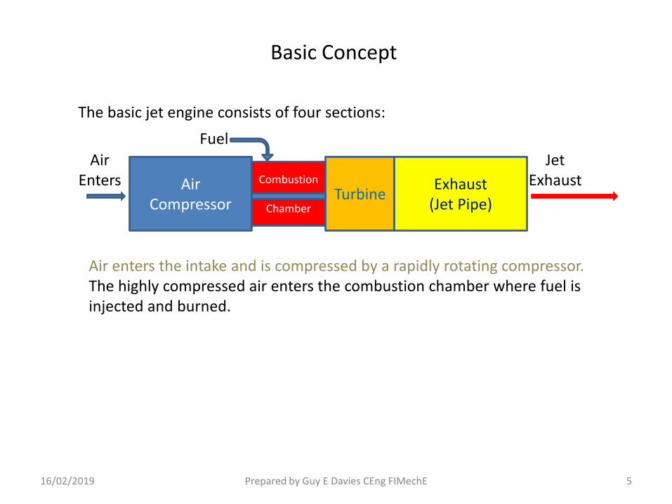
The basic jet engine consists of four sections:
Air enters the intake and is compressed by a rapidly rotating compressor.The highly compressed air enters the combustion chamber where fuel is injected and burned.
AirCompressor
Combustion
ChamberTurbine
Exhaust(Jet Pipe)
AirEnters
JetExhaust
Fuel

16/02/2019 Prepared by Guy E Davies CEng FIMechE 6
Basic Concept
The basic jet engine consists of four sections:
Air enters the intake and is compressed by a rapidly rotating compressor.The highly compressed air enters the combustion chamber where fuel is injected and burned.The very hot, high pressure exhaust drives a turbine which is connected by a shaft to turn the compressor.
AirCompressor
Combustion
ChamberTurbine
Exhaust(Jet Pipe)
AirEnters
JetExhaust
Fuel

16/02/2019 Prepared by Guy E Davies CEng FIMechE 7
Basic Concept
The basic jet engine consists of four sections:
Air enters the intake and is compressed by a rapidly rotating compressor.The highly compressed air enters the combustion chamber where fuel is injected and burned.The very hot, high pressure exhaust drives a turbine which is connected by a shaft to turn the compressor.The exhaust from the turbine accelerates down the jet pipe to exit at high velocity.
AirCompressor
Combustion
ChamberTurbine
Exhaust(Jet Pipe)
AirEnters
JetExhaust
Fuel

16/02/2019 Prepared by Guy E Davies CEng FIMechE 8
Basic Concept
The basic jet engine consists of four sections:
Air enters the intake and is compressed by a rapidly rotating compressor.The highly compressed air enters the combustion chamber where fuel is injected and burned.The very hot, high pressure exhaust drives a turbine which is connected by a shaft to turn the compressor.The exhaust from the turbine accelerates down the jet pipe to exit at high velocity.Thrust is produced because the intake air has been accelerated and blown out of the exhaust at much higher velocity. (Force = Mass x Acceleration).
AirCompressor
Combustion
ChamberTurbine
Exhaust(Jet Pipe)
AirEnters
JetExhaust
Fuel
16/02/2019 Prepared by Guy E Davies CEng FIMechE 9
Basic Concept
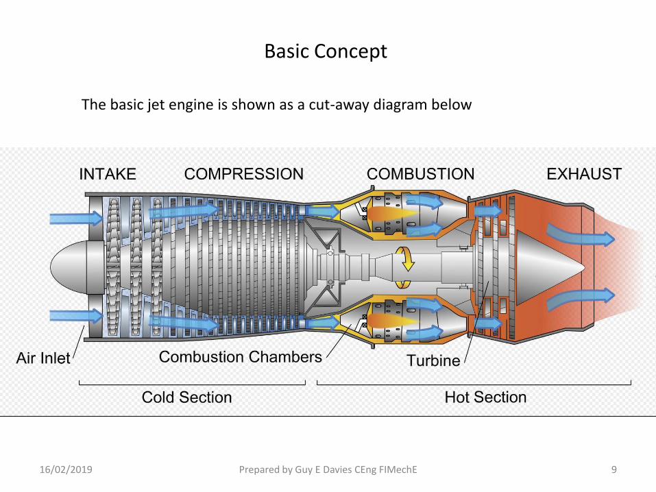
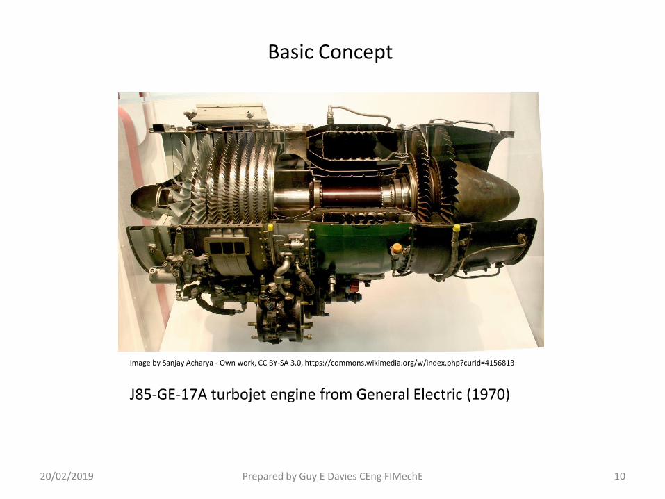
The basic jet engine is shown as a cut-away diagram below
20/02/2019 Prepared by Guy E Davies CEng FIMechE 10
Basic Concept
Image by Sanjay Acharya - Own work, CC BY-SA 3.0, https://commons.wikimedia.org/w/index.php?curid=4156813
J85-GE-17A turbojet engine from General Electric (1970)

Compressor
16/02/2019 Prepared by Guy E Davies CEng FIMechE 11
Rotor Blades Stator Blades
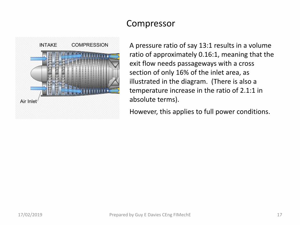
The compressor consists of multiple stages of rotating blades (rotor blades), each stage compressing the intake air a small amount. The rotating stages swirl the air so a ring of fixed blades (stator blades) is placed between each stage of rotating blades, and at the exit of the final stage to straighten the airflow.
17/02/2019 Prepared by Guy E Davies CEng FIMechE 12
Compressor
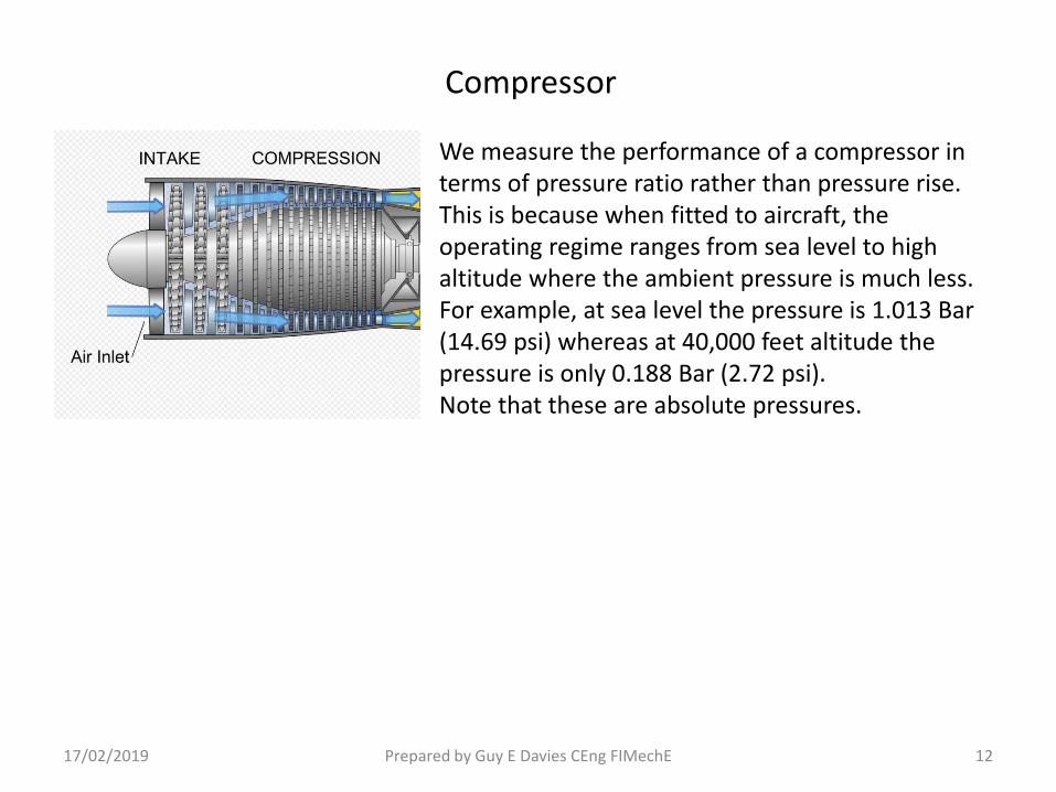
We measure the performance of a compressor in terms of pressure ratio rather than pressure rise.This is because when fitted to aircraft, the operating regime ranges from sea level to high altitude where the ambient pressure is much less.For example, at sea level the pressure is 1.013 Bar (14.69 psi) whereas at 40,000 feet altitude the pressure is only 0.188 Bar (2.72 psi).Note that these are absolute pressures.
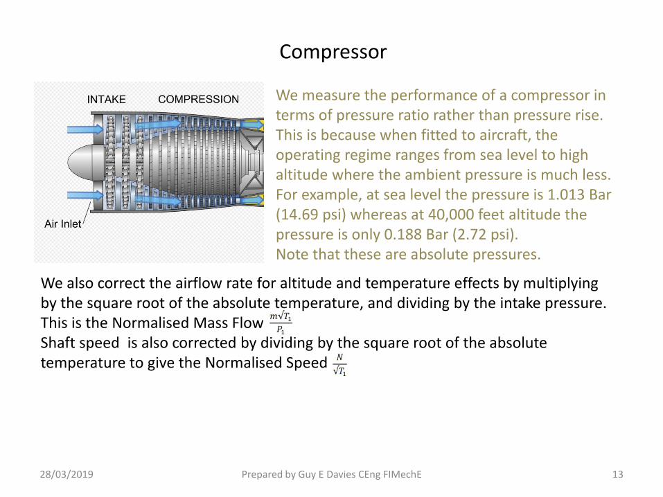
We also correct the airflow rate for altitude and temperature effects by multiplying by the square root of the absolute temperature, and dividing by the intake pressure. This is the Normalised Mass Flow Shaft speed is also corrected by dividing by the square root of the absolute temperature to give the Normalised Speed
We measure the performance of a compressor in terms of pressure ratio rather than pressure rise.This is because when fitted to aircraft, the operating regime ranges from sea level to high altitude where the ambient pressure is much less.For example, at sea level the pressure is 1.013 Bar (14.69 psi) whereas at 40,000 feet altitude the pressure is only 0.188 Bar (2.72 psi).Note that these are absolute pressures.
28/03/2019 Prepared by Guy E Davies CEng FIMechE 13
Compressor

26/03/2019 Prepared by Guy E Davies CEng FIMechE 14
Compressor
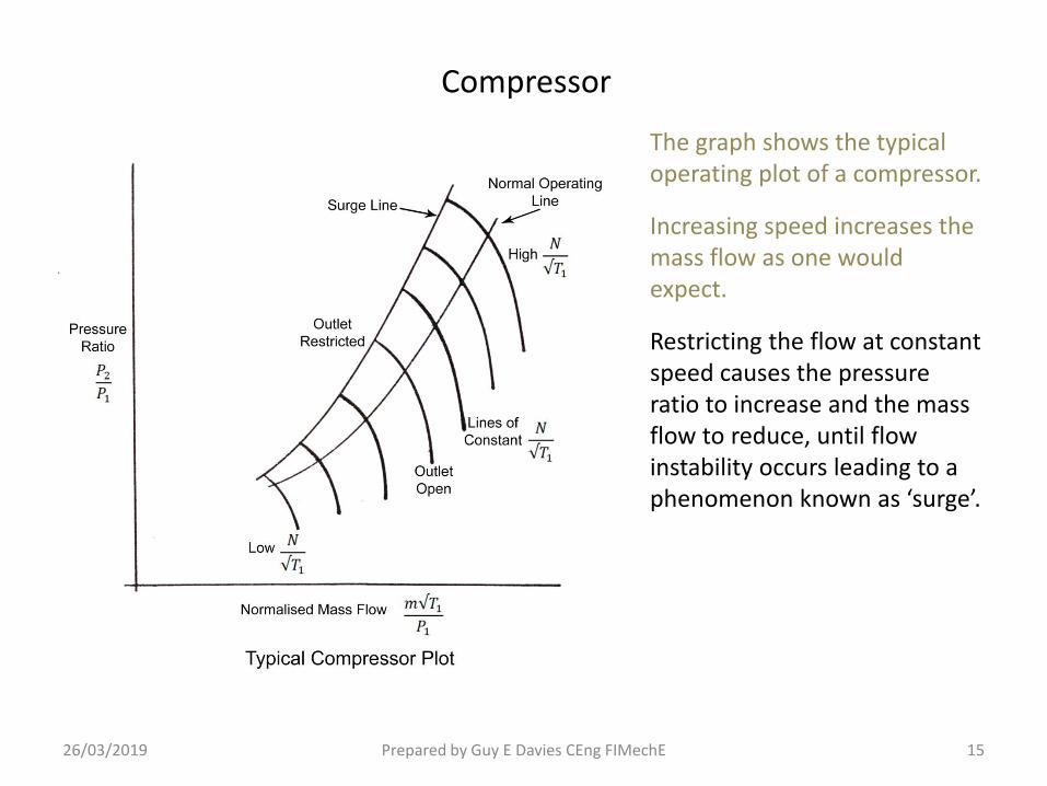
The graph shows the typical operating plot of a compressor.
Increasing speed increases the mass flow as one would expect.
26/03/2019 Prepared by Guy E Davies CEng FIMechE 15
Compressor
The graph shows the typical operating plot of a compressor.
Increasing speed increases the mass flow as one would expect.
Restricting the flow at constant speed causes the pressure ratio to increase and the mass flow to reduce, until flow instability occurs leading to a phenomenon known as ‘surge’.

26/03/2019 Prepared by Guy E Davies CEng FIMechE 16
Compressor
The graph shows the typical operating plot of a compressor.
Increasing speed increases the mass flow as one would expect.
Restricting the flow at constant speed causes the pressure ratio to increase and the mass flow to reduce, until flow instability occurs leading to a phenomenon known as ‘surge’.
Note that this represents a basic compressor operating at modest pressure ratios. The normal operating line follows the line of maximum efficiency.
17/02/2019 Prepared by Guy E Davies CEng FIMechE 17
Compressor
A pressure ratio of say 13:1 results in a volume ratio of approximately 0.16:1, meaning that the exit flow needs passageways with a cross section of only 16% of the inlet area, as illustrated in the diagram. (There is also a temperature increase in the ratio of 2.1:1 in absolute terms).
However, this applies to full power conditions.
17/02/2019 Prepared by Guy E Davies CEng FIMechE 18
Compressor
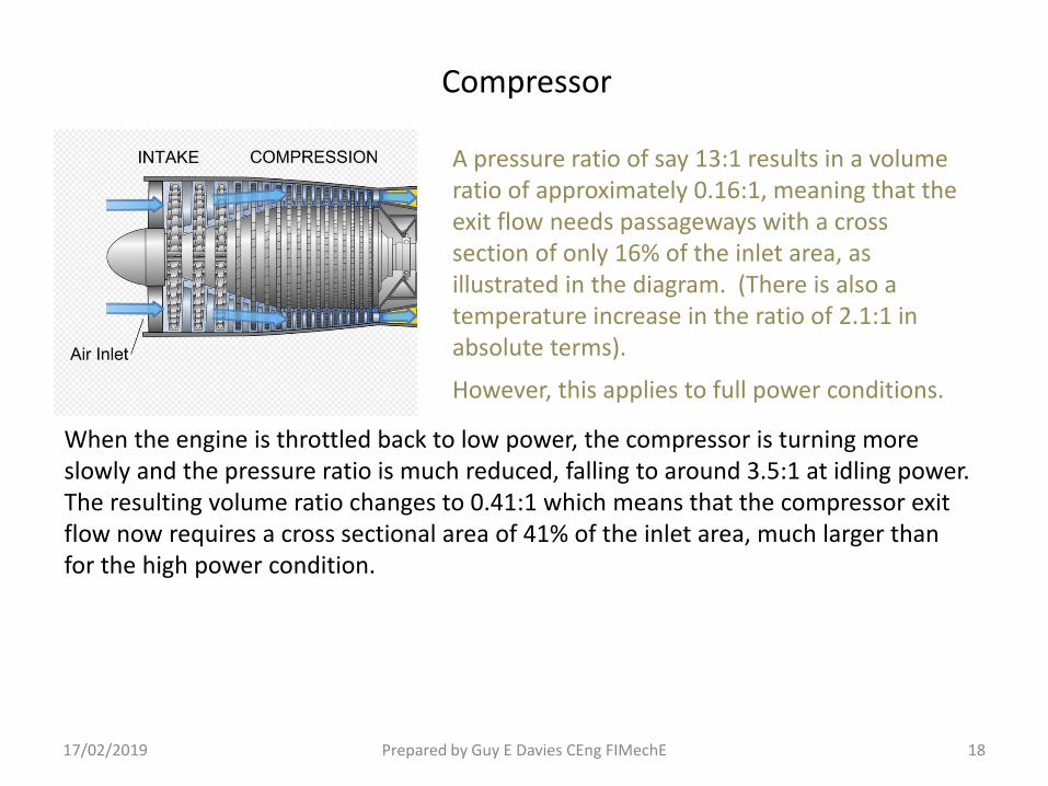
A pressure ratio of say 13:1 results in a volume ratio of approximately 0.16:1, meaning that the exit flow needs passageways with a cross section of only 16% of the inlet area, as illustrated in the diagram. (There is also a temperature increase in the ratio of 2.1:1 in absolute terms).
However, this applies to full power conditions.
When the engine is throttled back to low power, the compressor is turning more slowly and the pressure ratio is much reduced, falling to around 3.5:1 at idling power.The resulting volume ratio changes to 0.41:1 which means that the compressor exit flow now requires a cross sectional area of 41% of the inlet area, much larger than for the high power condition.

17/02/2019 Prepared by Guy E Davies CEng FIMechE 19
Compressor
A pressure ratio of say 13:1 results in a volume ratio of approximately 0.16:1, meaning that the exit flow needs passageways with a cross section of only 16% of the inlet area, as illustrated in the diagram. (There is also a temperature increase in the ratio of 2.1:1 in absolute terms).
However, this applies to full power conditions.
When the engine is throttled back to low power, the compressor is turning more slowly and the pressure ratio is much reduced, falling to around 3.5:1 at idling power.The resulting volume ratio changes to 0.41:1 which means that the compressor exit flow now requires a cross sectional area of 41% of the inlet area, much larger than for the high power condition.
The inlet is now taking in more air than can be accepted by the exit area and ultimately flow breakdown can occur, causing surge. This results in unstable operation of the engine and in extreme cases can cause damage.

30/03/2019 Prepared by Guy E Davies CEng FIMechE 20
Compressor
The graph shows the operating plot of a high performance fixed geometry compressor (iea compressor working over a high pressure ratio range).
Note that the steady running line crosses the surge boundary as the speed is reduced.

17/02/2019 Prepared by Guy E Davies CEng FIMechEPrepared by Guy E Davies CEng FIMechE 21Prepared by Guy E Davies CEng FIMechEPrepared by Guy E Davies CEng FIMechEPrepared by Guy E Davies CEng FIMechE
Compressor
The simplest way to control this problem is simply to dump the excess airflow through valves known as Bleed Valves. These discharge compressor air overboard from the compressor exit or even from part way along.However, this is inefficient as it wastes the power already expended on compressing the air, so is normally only used at very low power.
Bleed Valve ClosedHigh Power
Bleed Valve OpenLow Power Bleed Air

18/02/2019 Prepared by Guy E Davies CEng FIMechE 22
Compressor
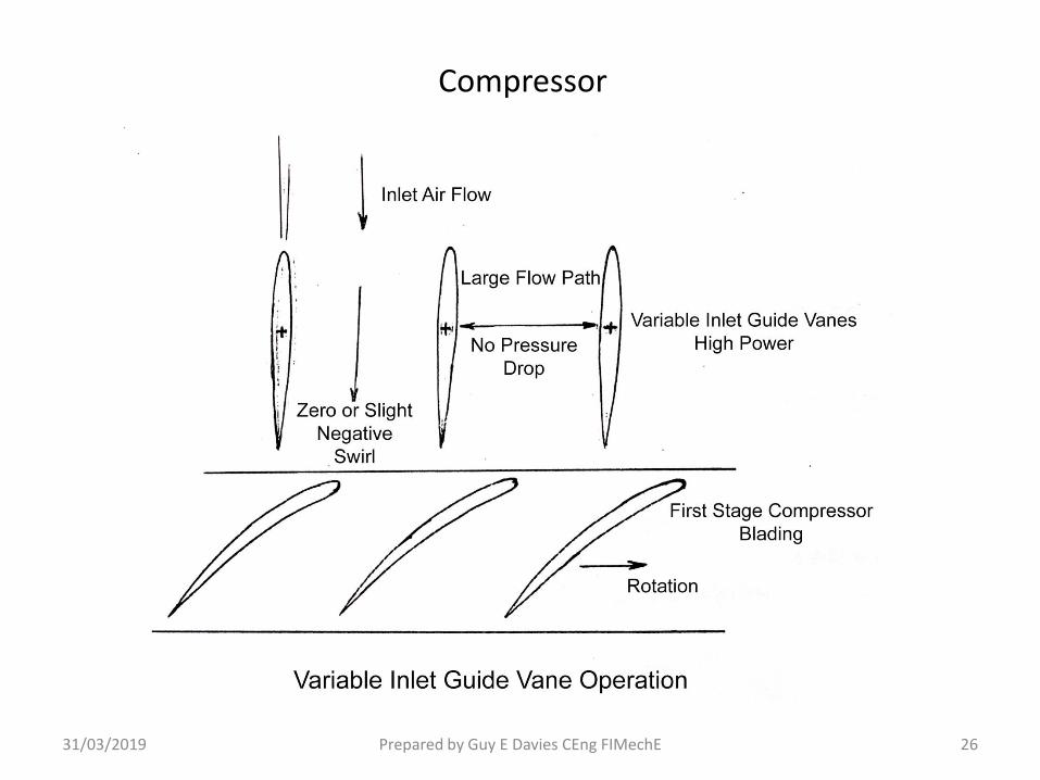
A more efficient, but more complex way to deal with low power conditions is to use variable geometry to reconfigure the compressor, and thus alter the flow.A ring of pivoted stator vanes is placed at the inlet to the compressor and these can be turned to swirl the air as it enters the inlet. At low power the vanes are turned to swirl the air in the direction of the compressor rotation, reducing the load on the first few rotor stages, and also effectively reducing the inlet area. These are called Variable Inlet Guide Vanes (VIGV)
Bleed Valve
VIGV
VIGV Actuating Ring
VIGV Actuator

19/04/2019 Prepared by Guy E Davies CEng FIMechE 23
Compressor
Each guide vane is pivoted in the compressor casing and connected by mechanical linkage to an actuating ring which can be rotated to turn the vanes. A hydraulic or electric actuator moves the actuating ring as part of the engine control system. Typically the vanes will be set at about 0° swirl for high power and progressively turned to give about 40° swirl at low power.
Bleed Valve
VIGV
VIGV Actuating Ring
VIGV Actuator

19/02/2019 Prepared by Guy E Davies CEng FIMechE 24
Compressor
Each guide vane is pivoted in the compressor casing and connected by mechanical linkage to an actuating ring which can be rotated to turn the vanes. A hydraulic or electric actuator moves the actuating ring as part of the engine control system. Typically the vanes will be set at about 0° swirl for high power and progressively turned to give about 40° swirl at low power.On some high performance compressors it is common to vary the swirl on several stages of stator vanes as well as the inlet guide vanes.
Bleed Valve
VIGV
VIGV Actuating Ring
VIGV Actuator Variable Stator Vanes

19/02/2019 Prepared by Guy E Davies CEng FIMechE 25
Compressor
Each guide vane is pivoted in the compressor casing and connected by mechanical linkage to an actuating ring which can be rotated to turn the vanes. A hydraulic or electric actuator moves the actuating ring as part of the engine control system. Typically the vanes will be set at about 0° swirl for high power and progressively turned to give about 40° swirl at low power.On some high performance compressors it is common to vary the swirl on several stages of stator vanes as well as the inlet guide vanes.
Bleed Valve
VIGV
VIGV Actuating Ring
VIGV Actuator Variable Stator Vanes
Typically, bleed valves may be used for very low power, with VIGV and possibly variable stator vanes being used for intermediate power.
31/03/2019 Prepared by Guy E Davies CEng FIMechE 26
Compressor

31/03/2019 Prepared by Guy E Davies CEng FIMechE 27
Compressor
30/03/2019 Prepared by Guy E Davies CEng FIMechE 28
Compressor
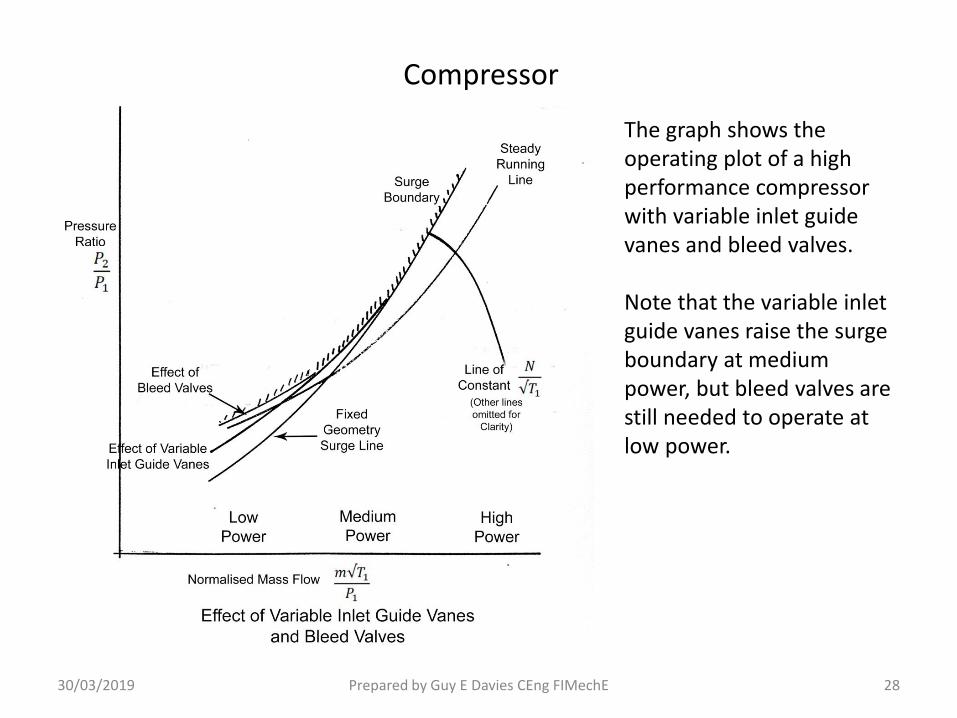
The graph shows the operating plot of a high performance compressor with variable inlet guide vanes and bleed valves.
Note that the variable inlet guide vanes raise the surge boundary at medium power, but bleed valves are still needed to operate at low power.

Combustion Chamber
20/02/2019 Prepared by Guy E Davies CEng FIMechE 29
Fuel is pumped at high pressure into the combustion chamber where it is atomised and mixed with the air from the compressor. It is ignited by spark igniters during engine start and then the flame is self sustaining.
Compressor Air

20/02/2019 Prepared by Guy E Davies CEng FIMechE 30
Combustion Chamber
Fuel is pumped at high pressure into the combustion chamber where it is atomised and mixed with the air from the compressor. It is ignited by spark igniters during engine start and then the flame is self sustaining.
The combustion chamber is designed to mix the optimum amount of air with the fuel for stable and efficient burn, with excess air then mixing with the hot flame downstream of the combustion zone.
20/02/2019 Prepared by Guy E Davies CEng FIMechE 31
Combustion Chamber
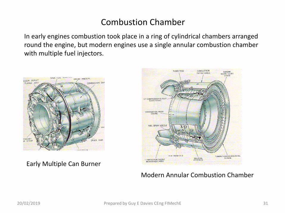
In early engines combustion took place in a ring of cylindrical chambers arranged round the engine, but modern engines use a single annular combustion chamber with multiple fuel injectors.
Early Multiple Can Burner
Modern Annular Combustion Chamber
Turbine
20/02/2019 Prepared by Guy E Davies CEng FIMechE 32
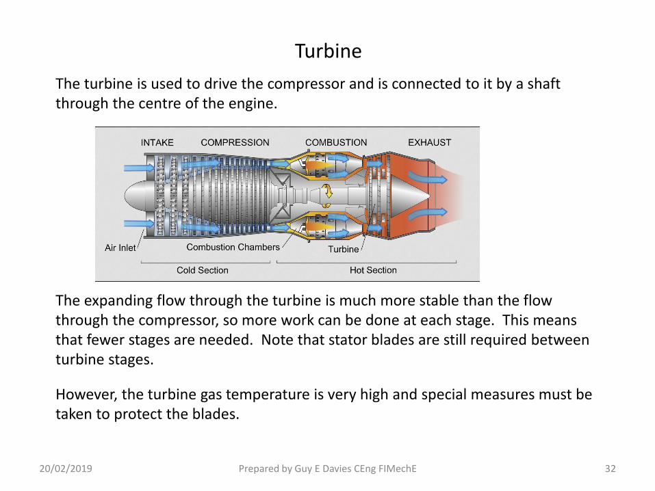
The turbine is used to drive the compressor and is connected to it by a shaft through the centre of the engine.
The expanding flow through the turbine is much more stable than the flow through the compressor, so more work can be done at each stage. This means that fewer stages are needed. Note that stator blades are still required between turbine stages.
However, the turbine gas temperature is very high and special measures must be taken to protect the blades.
20/02/2019 Prepared by Guy E Davies CEng FIMechE 33
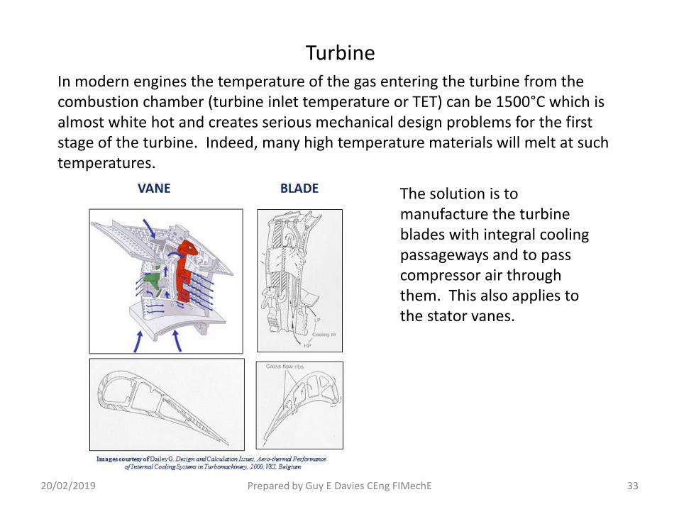
TurbineIn modern engines the temperature of the gas entering the turbine from the combustion chamber (turbine inlet temperature or TET) can be 1500°C which is almost white hot and creates serious mechanical design problems for the first stage of the turbine. Indeed, many high temperature materials will melt at such temperatures.
The solution is to manufacture the turbine blades with integral cooling passageways and to pass compressor air through them. This also applies to the stator vanes.
20/02/2019 Prepared by Guy E Davies CEng FIMechE 34
Turbine
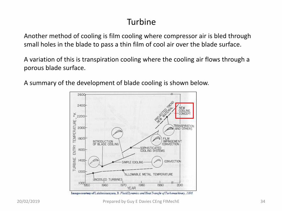
Another method of cooling is film cooling where compressor air is bled through small holes in the blade to pass a thin film of cool air over the blade surface.
A variation of this is transpiration cooling where the cooling air flows through a porous blade surface.
A summary of the development of blade cooling is shown below.

Jet Pipe
20/02/2019 Prepared by Guy E Davies CEng FIMechE 35
The function of the jet pipe is to accelerate the turbine exhaust gas to a high exit velocity to generate thrust, whilst not imposing a back pressure on the turbine, which would reduce efficiency.

21/02/2019 Prepared by Guy E Davies CEng FIMechE 36
Jet Pipe
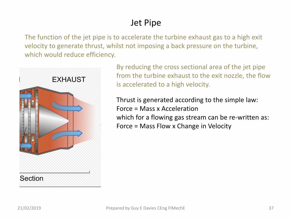
The function of the jet pipe is to accelerate the turbine exhaust gas to a high exit velocity to generate thrust, whilst not imposing a back pressure on the turbine, which would reduce efficiency.
By reducing the cross sectional area of the jet pipe from the turbine exhaust to the exit nozzle, the flow is accelerated to a high velocity.
21/02/2019 Prepared by Guy E Davies CEng FIMechE 37
Jet Pipe
The function of the jet pipe is to accelerate the turbine exhaust gas to a high exit velocity to generate thrust, whilst not imposing a back pressure on the turbine, which would reduce efficiency.
By reducing the cross sectional area of the jet pipe from the turbine exhaust to the exit nozzle, the flow is accelerated to a high velocity.
Thrust is generated according to the simple law:Force = Mass x Accelerationwhich for a flowing gas stream can be re-written as:Force = Mass Flow x Change in Velocity
21/02/2019 Prepared by Guy E Davies CEng FIMechE 38
Jet Pipe
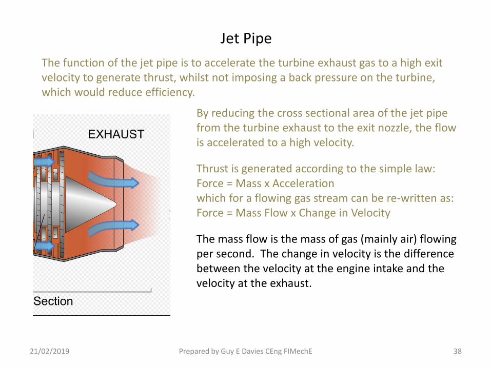
The function of the jet pipe is to accelerate the turbine exhaust gas to a high exit velocity to generate thrust, whilst not imposing a back pressure on the turbine, which would reduce efficiency.
By reducing the cross sectional area of the jet pipe from the turbine exhaust to the exit nozzle, the flow is accelerated to a high velocity.
Thrust is generated according to the simple law:Force = Mass x Accelerationwhich for a flowing gas stream can be re-written as:Force = Mass Flow x Change in Velocity
The mass flow is the mass of gas (mainly air) flowing per second. The change in velocity is the difference between the velocity at the engine intake and the velocity at the exhaust.

21/02/2019 Prepared by Guy E Davies CEng FIMechE 39
Jet Pipe
The function of the jet pipe is to accelerate the turbine exhaust gas to a high exit velocity to generate thrust, whilst not imposing a back pressure on the turbine, which would reduce efficiency.
By reducing the cross sectional area of the jet pipe from the turbine exhaust to the exit nozzle, the flow is accelerated to a high velocity.
Thrust is generated according to the simple law:Force = Mass x Accelerationwhich for a flowing gas stream can be re-written as:Force = Mass Flow x Change in Velocity
The mass flow is the mass of gas (mainly air) flowing per second. The change in velocity is the difference between the velocity at the engine intake and the velocity at the exhaust.
The maximum exit velocity occurs at full power and is usually at sonic speed.

Fan
21/02/2019 Prepared by Guy E Davies CEng FIMechE 40
The simple jet engine produces a relatively small jet of very high velocity exhaust gas (mainly air). For commercial aircraft, working at fairly high subsonic Mach number (0.75 – 0.85) this is not the most efficient approach. For these conditions a larger jet having a lower velocity would be more efficient.

21/02/2019 Prepared by Guy E Davies CEng FIMechE 41
Fan
The simple jet engine produces a relatively small jet of very high velocity exhaust gas (mainly air). For commercial aircraft, working at fairly high subsonic Mach number (0.75 – 0.85) this is not the most efficient approach. For these conditions a larger jet having a lower velocity would be more efficient.
At the other extreme, a propeller produces a very large jet (ie slipstream) with only a relatively small increase in velocity. Whilst this is highly efficient at low forward speed, it becomes much less efficient at moderately high subsonic Mach number because the blade tips start to exceed the speed of sound and serious energy losses occur.

21/02/2019 Prepared by Guy E Davies CEng FIMechE 42
The simple jet engine produces a relatively small jet of very high velocity exhaust gas (mainly air). For commercial aircraft, working at fairly high subsonic Mach number (0.75 – 0.85) this is not the most efficient approach. For these conditions a larger jet having a lower velocity would be more efficient.
At the other extreme, a propeller produces a very large jet (ie slipstream) with only a relatively small increase in velocity. Whilst this is highly efficient at low forward speed, it becomes much less efficient at moderately high subsonic Mach number because the blade tips start to exceed the speed of sound and serious energy losses occur.
An in-between solution is to use a large fan driven by the engine, acting like a small propeller inside a cowling. This produces a large exhaust jet with a velocity less than that from a simple jet engine, but higher than could be obtained from a propeller.
Fan
23/03/2019 Prepared by Guy E Davies CEng FIMechE 43
Fan
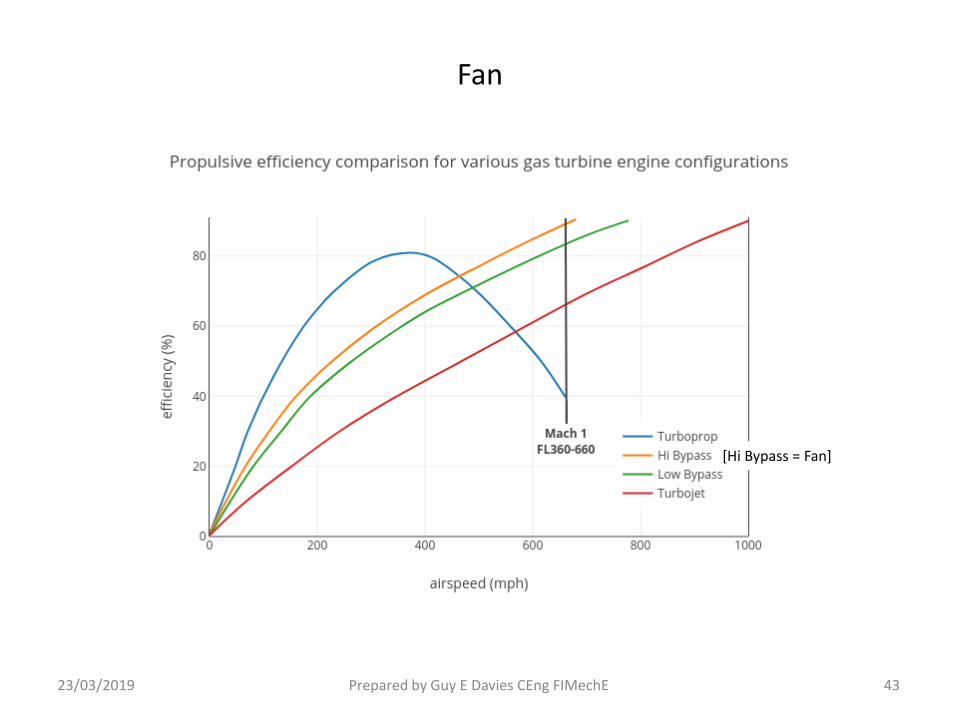
[Hi Bypass = Fan]
21/02/2019 Prepared by Guy E Davies CEng FIMechE 44
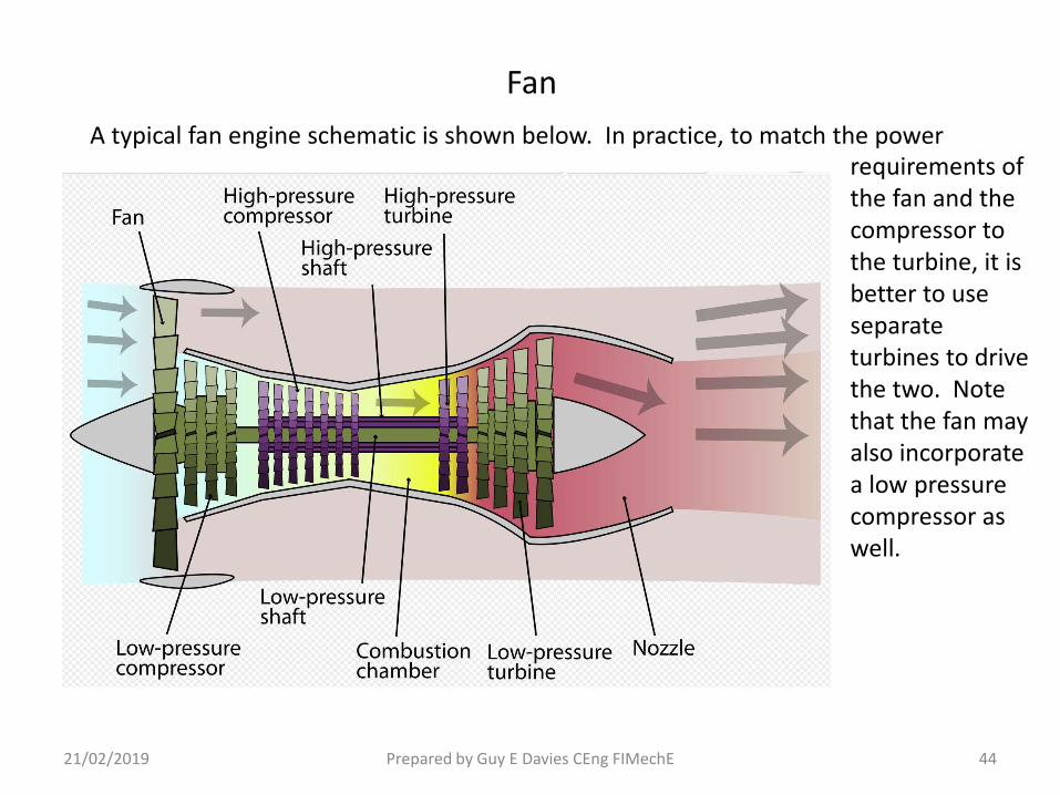
A typical fan engine schematic is shown below. In practice, to match the power
Fan
requirements of the fan and the compressor to the turbine, it is better to use separate turbines to drive the two. Note that the fan may also incorporate a low pressure compressor as well.
22/03/2019 Prepared by Guy E Davies CEng FIMechE 45
Fan
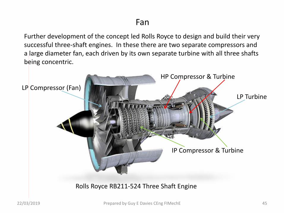
Further development of the concept led Rolls Royce to design and build their very successful three-shaft engines. In these there are two separate compressors and a large diameter fan, each driven by its own separate turbine with all three shafts being concentric.
HP Compressor & Turbine
IP Compressor & Turbine
LP Turbine
LP Compressor (Fan)
Rolls Royce RB211-524 Three Shaft Engine

23/03/2019 Prepared by Guy E Davies CEng FIMechE 46
Fan
TechnologyThe three-shaft architecture allows an engine to have fewer stages, giving a shorter, stiffer structure that allows the rotors to run at their optimum speeds.The innovative wide-chord fan blades allow a reduction in the number of total fan blades - increasing efficiency, reducing noise and giving unrivalled protection against foreign object damage.Through the Rolls-Royce concept of family designs, the RB211-524G/H-T was upgraded with 04 module HP (high pressure) technology developed on the Trent 700 engine family in 1997.In the RB211-524G/H-T, the HP turbine system is designed to operate at Trent 700 temperatures that are significantly higher than the original RB211-524.The Trent style combustor reduces NOx emissions by 40 per cent, making the RB211-524G/H-T the engine with the lowest NOx emissions on the Boeing 747-400.
The following description is from the Rolls Royce website:
The engine also utilises Variable Inlet Guide Vanes and Compressor Bleed Valves for good control at low and intermediate power settings. (The Trent is a later, more powerful engine of similar design).

23/03/2019 Prepared by Guy E Davies CEng FIMechE 47
Engine Operating Conditions

Fuel Control
23/03/2019 Prepared by Guy E Davies CEng FIMechE 48
When the engine is running at low or intermediate power and the throttle is opened further to accelerate to a higher power, the extra fuel being burned causes a rise in combustion temperature which in turn causes a transient increase in pressure. This back pressure at the compressor outlet tries to restrict the compressor outlet flow and if taken to extreme will cause flow instability in the compressor leading to complete flow breakdown known as ‘surge’.

23/03/2019 Prepared by Guy E Davies CEng FIMechE 49
Fuel Control
When the engine is running at low or intermediate power and the throttle is opened further to accelerate to a higher power, the extra fuel being burned causes a rise in combustion temperature which in turn causes a transient increase in pressure. This back pressure at the compressor outlet tries to restrict the compressor outlet flow and if taken to extreme will cause flow instability in the compressor leading to complete flow breakdown known as ‘surge’.
Consequently, it is necessary to limit the amount of extra fuel that can be added while the engine accelerates. As it does so, more and more fuel can then be added to bring the engine to full power.

23/03/2019 Prepared by Guy E Davies CEng FIMechE 50
Fuel Control
When the engine is running at low or intermediate power and the throttle is opened further to accelerate to a higher power, the extra fuel being burned causes a rise in combustion temperature which in turn causes a transient increase in pressure. This back pressure at the compressor outlet tries to restrict the compressor outlet flow and if taken to extreme will cause flow instability in the compressor leading to complete flow breakdown known as ‘surge’.
Consequently, it is necessary to limit the amount of extra fuel that can be added while the engine accelerates. As it does so, more and more fuel can then be added to bring the engine to full power.
A fuel control unit solves those problems by acting as an intermediary between the pilot’s controls and the fuel valve. The pilot has a power lever which only controls the potential of the engine, not the actual fuel flow. The fuel control unit acts as a computer to determine the amount of fuel needed to deliver the power requested by the pilot.
23/03/2019 Prepared by Guy E Davies CEng FIMechE 51
Fuel Control
When the engine is running at low or intermediate power and the throttle is opened further to accelerate to a higher power, the extra fuel being burned causes a rise in combustion temperature which in turn causes a transient increase in pressure. This back pressure at the compressor outlet tries to restrict the compressor outlet flow and if taken to extreme will cause flow instability in the compressor leading to complete flow breakdown known as ‘surge’.
Consequently, it is necessary to limit the amount of extra fuel that can be added while the engine accelerates. As it does so, more and more fuel can then be added to bring the engine to full power.
A fuel control unit solves those problems by acting as an intermediary between the pilot’s controls and the fuel valve. The pilot has a power lever which only controls the potential of the engine, not the actual fuel flow. The fuel control unit acts as a computer to determine the amount of fuel needed to deliver the power requested by the pilot.
A similar degree of control is also provided when throttling back to prevent flame-out occurring.

31/03/2019 Prepared by Guy E Davies CEng FIMechE 52
Fuel Control
The fuel control unit regulates the fuel flow to avoid surge during engine acceleration, and weak extinction during deceleration.

31/03/2019 Prepared by Guy E Davies CEng FIMechE 53
Fuel Control
The fuel control unit regulates the fuel flow to avoid surge during engine acceleration, and weak extinction during deceleration.
Thus if the throttle is slammed fully open from low power, the fuel flow is limited by the control system to just below the surge limit, and is increased progressively as the engine accelerates. When the engine speed reaches required value, the fuel flow is reduced to the steady running value.

31/03/2019 Prepared by Guy E Davies CEng FIMechE 54
Fuel Control
The fuel control unit regulates the fuel flow to avoid surge during engine acceleration, and weak extinction during deceleration.
Thus if the throttle is slammed fully open from low power, the fuel flow is limited by the control system to just below the surge limit, and is increased progressively as the engine accelerates. When the engine speed reaches required value, the fuel flow is reduced to the steady running value.
A similar degree of control prevents flame extinction when the throttle is closed.

23/03/2019 Prepared by Guy E Davies CEng FIMechE 55
Fuel Control
This diagram shows a schematic of the fuel flow control fitted to the Pratt & Whitney F100 engine used on the US Airforce F-15 and F-16 combat aircraft. The system uses digital control to compute the correct amount of fuel for any operating condition.
{Note that it also includes the fuel control for After-Burning ieReheat (A/B Fuel Flow) which is used only on combat aircraft to boost thrust}.
The gas turbine part of the fuel control is similar to that used in commercial fan engines.

24/03/2019 Prepared by Guy E Davies CEng FIMechE 56
How a Jet Engine Works
There is, of course, a lot more to the jet engine.
Major systems and components include:Variable Inlet Guide Vane ControlBleed ValvesFuel Control SystemFuel PumpsLubrication SystemElectrical GeneratorStarterCabin Air BleedReheat (After-Burning) on military engines

08/04/2019 Prepared by Guy E Davies CEng FIMechE 57
How a Jet Engine Works
What of the future?
The hunt for better economyIncreased pressure ratio – higher temperature – increased NOx
Efforts to reduce emissions (esp Nox)Combustion chamber designCooler burning
Search for new higher temperature materials
New manufacturing methods3D printing of components
Increased electronic controlNew sensorsControl closer to critical limits
08/04/2019 Prepared by Guy E Davies CEng FIMechE 58
How a Jet Engine Works
Let’s finish with a few thoughts.First a quote from the National Academy of Sciences ca 1940

08/04/2019 Prepared by Guy E Davies CEng FIMechE 59
How a Jet Engine Works
Let’s finish with a few thoughts.First a quote from the National Academy of Sciences ca 1940
And now a couple of pictures
Whittle prototype 1939. Thrust 850 lb
08/04/2019 Prepared by Guy E Davies CEng FIMechE 60
How a Jet Engine Works
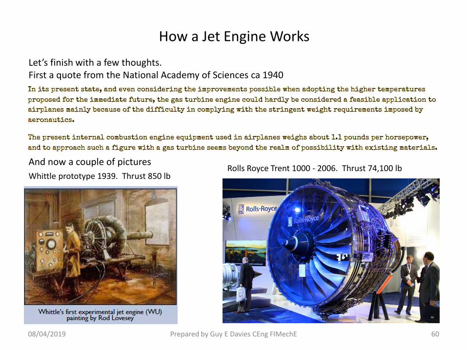
Let’s finish with a few thoughts.First a quote from the National Academy of Sciences ca 1940
And now a couple of picturesRolls Royce Trent 1000 - 2006. Thrust 74,100 lb
Whittle prototype 1939. Thrust 850 lb


