30
National Radio Astronomy Observatory Sept. 2005 – Indiana University How do Radio Telescopes work? K. Y. Lo

National Radio Astronomy ObservatorySept. 2005 – Indiana University
How do Radio Telescopes work?
K. Y. Lo

National Radio Astronomy Observatory
September 2005 – Indiana Universe
Electromagnetic Radiation
Wavelength
Radio Detection techniques developed from meter-wave to submillimeter-wave: = 1 meter = 300 MHz
= 1 mm = 300 GHz

General Antenna TypesWavelength > 1 m (approx) Wire Antennas
Dipole
Yagi
Helix
or arrays of these
Wavelength < 1 m (approx) Reflector antennas
Wavelength = 1 m (approx) Hybrid antennas (wire reflectors or feeds)
Feed

National Radio Astronomy Observatory
Sept 2005: Indiana University
REFLECTOR TYPES
Prime focus Cassegrain focus
(GMRT) (AT)
Offset Cassegrain Naysmith
(VLA) (OVRO)
Beam Waveguide Dual Offset
(NRO) (ATA)

National Radio Astronomy Observatory
Sept 2005: Indiana University
REFLECTOR TYPES
Prime focus Cassegrain focus
(GMRT) (AT)
Offset Cassegrain Naysmith
(VLA) (OVRO)
Beam Waveguide Dual Offset
(NRO) (ATA)

National Radio Astronomy Observatory
Sept 2005: Indiana University
What do Radio Astronomers measure?
• Luminosity of a source: L = dE/dt erg/s• Flux of a source at distance R:
S = L/4R2 erg/s/cm2
• Flux measures how bright a star is. In optical astronomy, this is measured in magnitudes, a logarithmic measure of flux.
• Intensity: If a source is extended, its surface brightness varies across its extent. The surface brightness is the intensity, the amount of flux that originates from unit solid angle of the source:
I = dS/d erg/s/cm2/steradian

Measures of Radiation• The following should be clear: L = S d = 4R2 S for isotropic
source 4
S = I dsource
• Since astronomical sources emit a wide spectrum of radiation, L, S and I are all functions of or , and we need to be more precise and define:
• Luminosity density: L() = dL/d W/Hz• Flux density: S() = dS/d W/m2/Hz• Specific intensity: I() = dI/d W/m2/str/Hz• The specific intensity is the fundamental quantity
characterizing radiation. It is a function of frequency, direction, s, and time.
• In general, the energy crossing a unit area oriented at an angle to s, specified by the vector da, is given by
dE = I(, s, t) sda d d dt = I(, ) sda d d dt

National Radio Astronomy Observatory
Sept 2005: Indiana University
Analogs in optical astronomy
• Luminosity is given by absolute magnitude• Flux, or brightness, is given by magnitudes
within defined bands: U, B, V• Intensity, or surface brightness, is given by
magnitude per square arc-second• Optical measures are logarithmic because the eye is
roughly logarithmic in its perception of brightness
• Quantitatively, a picture is really an intensity distribution map

National Radio Astronomy Observatory
Sept 2005: Indiana University
Rayleigh-Jeans Law and Brightness Temperature
• The Specific Intensity of thermal radiation from a black-body at temperature T is given by the Planck Distribution:
I = (2h3/c2)/[exp(h/kT) 1]= (2hc3/2)/[exp(hc/kT) 1]= 2kT/2 if >> hc/kT or h << kT, R-J
Law• Brightness Temperature
Tb (2/2k) I = T for thermal radiation• Brightness temperature of the Earth at 100 MHz ~ 108 K
(due to TV stations)

National Radio Astronomy Observatory
Sept 2005: Indiana University
Antenna = Radio Telescope• The function of the antenna is to collect radio
waves, and each antenna presents a cross section, or Effective Area, Ae(, ), which depends on direction (, )
• The power collected per unit frequency by the antenna from within a solid angle d about the direction (, ) is given by
dP = ½ I (, ) Ae (, ) d W/Hz
The ½ is because the typical radio receiver detects only one polarization of the radiation which we assume to be unpolarized.

National Radio Astronomy Observatory
Sept 2005: Indiana University
• The power density collected by the antenna from all directions is
P = ½ I (, ) Ae (, ) d W/Hz
• Antenna Temperature TA is defined by
TA = P/k in K (Nyquist Theorem)• Therefore
TA = (1/2k) I (, ) Ae (, ) d K• For a point source, I = S (, )
kTA = ½ Ae,max S W/Hz
if Ae (, ) has a maximum value Ae,max at (, ) = (0, 0)
• (Maximum) Effective Area of an antenna:
Ae,max = ap Ag m2
where Ag is the geometric area and ap is the aperture efficiency.
But, for a dipole antenna, Ag is zero but Ae is not.

National Radio Astronomy Observatory
Sept 2005: Indiana University
• Antenna pattern:
Pn(,) = Ae(,)/Ae,max
Pn(0,0) = 1
if the pattern is maximum in the forward direction
• If the antenna is pointed at direction (o,o)
TA (o,o) = (1/2k) I (, ) Ae (o, o) d
In terms of Tb and Pn ,
TA (o,o) = (Ae,max/2) Tb (, ) Pn (o, o) d
= (1/A) Tb (, ) Pn (o, o) d
where 2/Ae,max= A. Note the antenna temperature, which measures the power density P (W/Hz) collected by the antenna is the convolution of the antenna pattern Pn with the source brightness distribution Tb

Antenna Properties
Effective area: Ae(,,) m2
On-axis response
Ae,max = Ag
= aperture efficiency
Normalized power pattern(primary beam)
Pn(,,) = Ae(,,)/Ae,max
Beam solid angle A= Pn(,,) d 4, = frequency
all sky = wavelength
Ae,max A = 2

National Radio Astronomy Observatory
Sept 2005: Indiana University
Mapping by an Antenna
TA (o,o) = (Ae,max/2) Tb (, ) Pn (o, o) d• Point source: Tb(, ) = (2/2k)S (, )
TA (o,o) = (Ae,max/2) (2/2k)S (, ) Pn (o, o) d
= (Ae,max/2k) S Pn (o, o) Antenna pattern can be determined by scanning a point
source If pointing at the point source, then kTA = ½ Ae,maxS If S is known, then Ae,max can be determined by measuring TA
• Unresolved source: s < m ~ A 2/Ae,max
TA (0, 0) = (Ae,max/2) Tb (, ) Pn (, ) d
= (s/ A) Tb = (m/ A) (s/ m) Tb
TA = m(s/ m) Tb Beam dilutionBeam dilution

Milky Way

National Radio Astronomy Observatory
Sept 2005: Indiana University
Maxwell Equations?• Radio telescopes operate in the physical optics regime,
~ D, instead of the geometric optics regime, << D, of optical telescope diffraction of radiation important
• Easier to think of a radio telescope in terms of transmitting radiation• A point source of radiation (transmitter) at the focus of a
paraboloid is designed to illuminate the aperture with a uniform electric field
• The diffraction of the electric field across the aperture according to Huygens’ Principle determines the propagation of the electric field outward from the aperture or primary telescope surface
• The transmitted electric field at a distant (far-field) point P in the direction (,) is given by the Fourier Transform of the electric field distribution across the aperture u(, ):
u(,) u(, ) exp[2( + )/] dd
National Radio Astronomy Observatory
Sept 2005: Indiana University
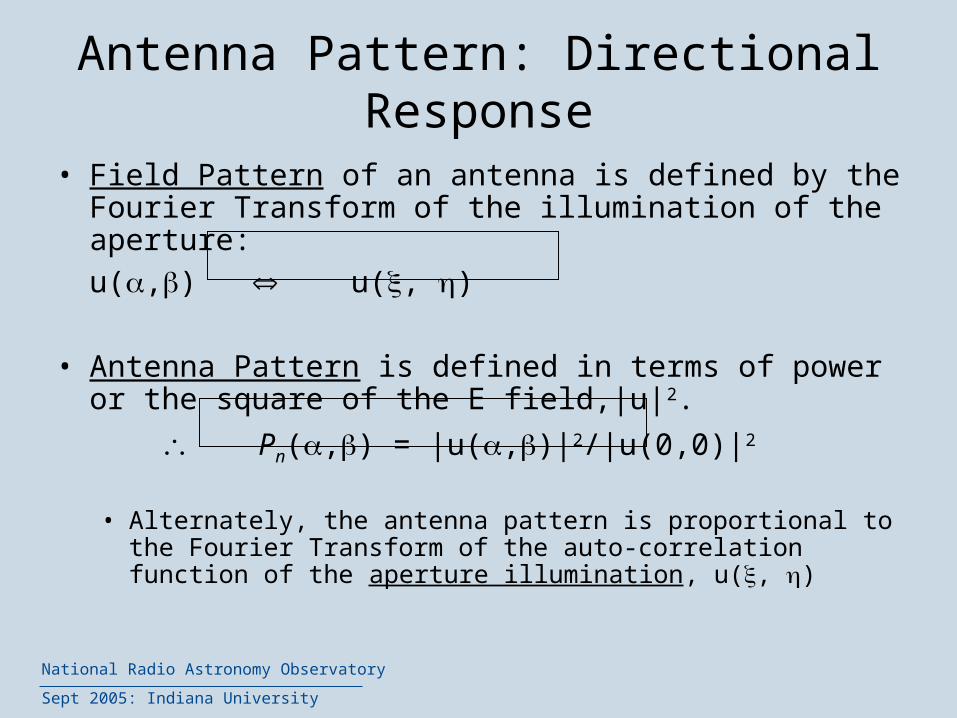
Antenna Pattern: Directional Response
• Field Pattern of an antenna is defined by the Fourier Transform of the illumination of the aperture:
u(,) u(, )
• Antenna Pattern is defined in terms of power or the square of the E field,|u|2.
Pn(,) = |u(,)|2/|u(0,0)|2
• Alternately, the antenna pattern is proportional to the Fourier Transform of the auto-correlation function of the aperture illumination, u(, )

Aperture-Beam Fourier Transform Relationship
u (, ) = aperture illumination
= Electric field distribution
across the aperture
(, ) = aperture coordinates ;
u(,) = far-field electric field
( , ) = direction relative to
“optical axis” of telescope
: :
|u ()|2
|u ()|2

National Radio Astronomy Observatory
Sept 2005: Indiana University
Antenna Key Features

Types of Antenna Mount
+ Beam does not rotate + Lower cost
+ Better tracking accuracy + Better gravity performance
- Higher cost - Beam rotates on the sky
- Poorer gravity performance
- Non-intersecting axis

National Radio Astronomy Observatory
Sept 2005: Indiana University
Antenna pointing designSubreflector mount
Quadrupod
El encoder
Reflector structure
Alidade structure
Rail flatness
Az encoder
Foundation

What happens to the signal collected by the antenna?
• At the focus, the radiation is collected by the receiver through a “feed” into a receiver that “pre-amplifies” the signal.
• Then, the signal is mixed with a local oscillator signal close in frequency to the observing frequency in a nonlinear device (mixer).
• The beat signal (IF or intermediate frequency signal) is usually amplified again before going through a bandwidth defining filter. (Frequency translation)
•Then the IF signal is detected by a square-law detector.
Pre-amplifier
LO at fLO
Amplification and filtering
Voltage |E|2
RF at fsky
IF at fsky fLO
Heterodyne Detection

VLA and EVLA Feed System Design
VLA
EVLA

National Radio Astronomy Observatory
Sept 2005: Indiana University
Wideband LBand OMT and Feed Horn

Receivers in the telescope
Gregorian Receiver Room
PF 1-1: 0.29 - 0.40 GHzPF 1-2: 0.38 - 0.52PF 1-3: 0.51 - 0.69PF 1-4: 0.68 - 0.92PF 2 : 0.91 - 1.23
L : 1.15 - 1.73 GHzS : 1.73 - 2.60C : 3.95 - 5.85X : 8.00 - 10.0Ku : 12.0 - 15.4K1 : 18.0 - 22.0K2 : 22.0 - 26.5Q : 40.0 - 52.0

National Radio Astronomy Observatory
Sept 2005: Indiana University
Radiometer Equation• For an unresolved source, the detection sensitivity of a
radio telescope is determined by the effective area of the telescope and the “noisiness” of the receiver
• For an unresolved source of a given flux, S, the expected antenna temperature is given by
kTA = ½ Ae,maxS
• The minimum detectable TA is given by
TA = Ts/(B)
where Ts is the system temperature of the receiver, B is the bandwidth and is the integration time, and is of order unity depending on the details of the system. The system temperature measures the noise power of the receiver (Ps = BkTs). In Radio Astronomy, detection is typically receiver noise dominated.
National Radio Astronomy Observatory
Sept 2005: Indiana University
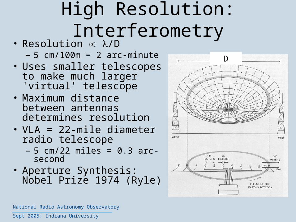
High Resolution: Interferometry
• Resolution /D– 5 cm/100m = 2 arc-minute
• Uses smaller telescopes to make much larger 'virtual' telescope
• Maximum distance between antennas determines resolution
• VLA = 22-mile diameter radio telescope– 5 cm/22 miles = 0.3 arc-second
• Aperture Synthesis: Nobel Prize 1974 (Ryle)
D

National Radio Astronomy Observatory
Sept 2005: Indiana University
VLA = Very Large Array (1980) Plain of San Augustine, New Mexico
27-antenna array: Extremely versatileMost productive telescope on ground
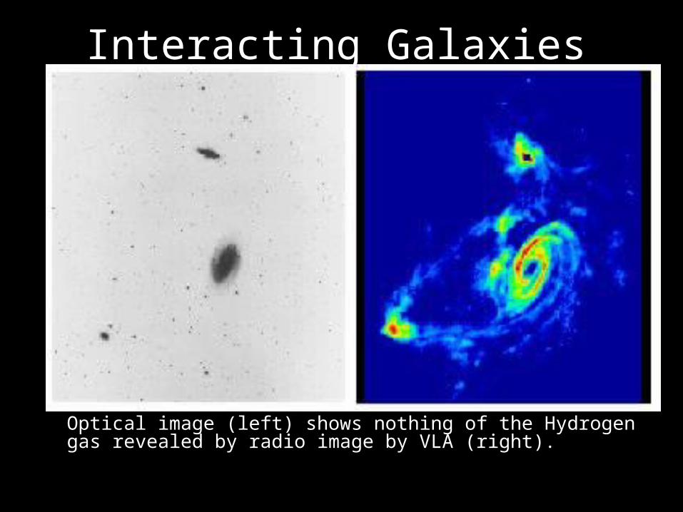
Interacting Galaxies
• Optical image (left) shows nothing of the Hydrogen gas revealed by radio image by VLA (right).

National Radio Astronomy Observatory
Sept 2005: Indiana University
Very Long Baseline Array
• 10 25m antennas• Continent-wide:
5400-mile diameter radio telescope• 6 cm/5400 miles = 0.001 arc-
second• Highest resolution
imaging telescope in astronomy:
1 milli-arc-second = reading a news-paper at a distance of 2000 km


