52
How It Relates To Duct Sizing Data not Dogma - July 2011 – Goldendale, WA Mark Jerome KAM Energy [email protected] 1

How It Relates To Duct Sizing Data not Dogma - July 2011 – Goldendale, WA
Mark Jerome KAM Energy [email protected]
1

Story Line The Players How The Data Has Been Collected Data We Have Had New Findings Others’ findings Possible Solutions Conclusion Q&A session
2

Issues found in the field during installations & quality assurance inspections of heat pump & air handler commissioning (NW PTCS Program)
Airflow is checked with the Energy Conservatory True Flow Plate
New heat pumps & ECM air handlers use more energy than anticipated
3
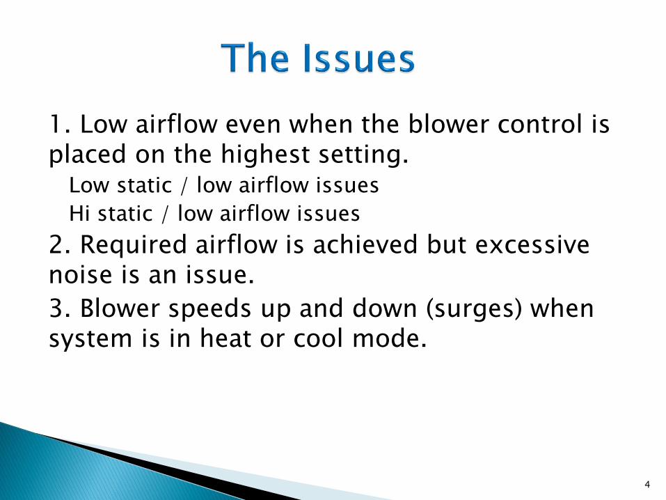
1. Low airflow even when the blower control is placed on the highest setting.
Low static / low airflow issues
Hi static / low airflow issues
2. Required airflow is achieved but excessive noise is an issue.
3. Blower speeds up and down (surges) when system is in heat or cool mode.
4
Lets explore these important issue in detail.
5

ECM 2.3 Motors
ECM X13 Motors
PCS Motors
Return Air Static Pressure of Ductwork
Supply Air Static Pressure of Ductwork
External Static Pressure of Ductwork
Modern Blower Controls
Communicating Blower Controls
6

7

It is designed to operate in constant torque mode with up to five discrete tap settings for OEM applications.
8
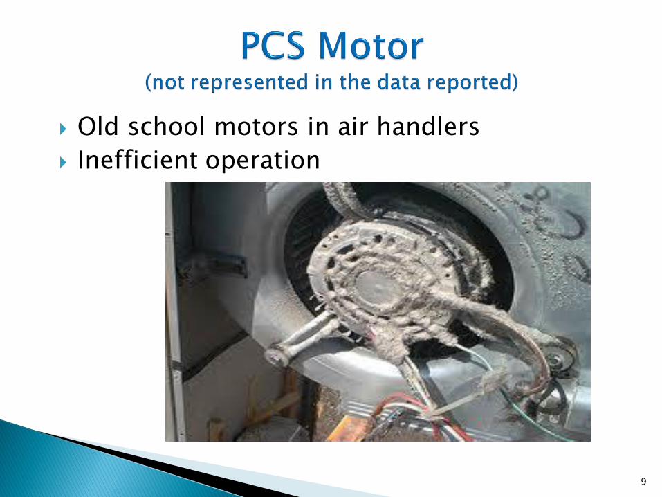
Old school motors in air handlers
Inefficient operation
9
10

11

.55
Typical Fan Curve
ESP CFM
.3 900
.4 850
.5 800
.7 675 8/31/2011 www.ptcsnw.com
12

Filter
Return Grille
Supply Grille
Heat Exchanger/Element Set
Negative Pressure
Positive Pressure
-88 Pa 30 Pa External
static = 88 + 30 = 118 Pa
Measuring ESP (External Static Pressure): Gas or Electric Furnace

Filter Coil Return Grille
Supply Grille
Negative Pressure
Positive Pressure
Standard Heat Pump (pull-through coil)
20 Pa
-65 Pa
External static = 65 + 20 = 85 Pa
Measuring ESP (External Static Pressure)

Filter
Return Grille
Supply Grille
Negative Pressure
Positive Pressure
Gas or Electric Furnace with AC or Heat Pump with Gas Back-up
-75 Pa 60 Pa External
static = 75 + 60 = 135 Pa
Heat Pump/AC
Coil
Heat Exchanger/Element Set
Measuring ESP (External Static Pressure)

16

17
18
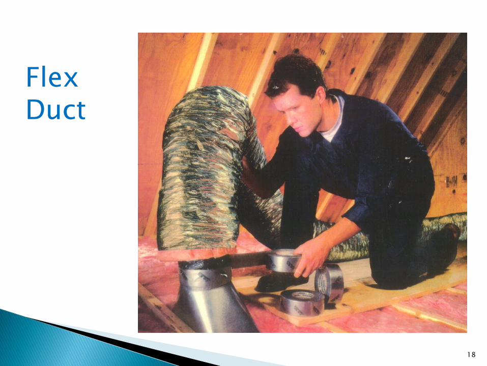
Flex Duct

Return Grille
Typical Supply Register
Boot (under register) 19
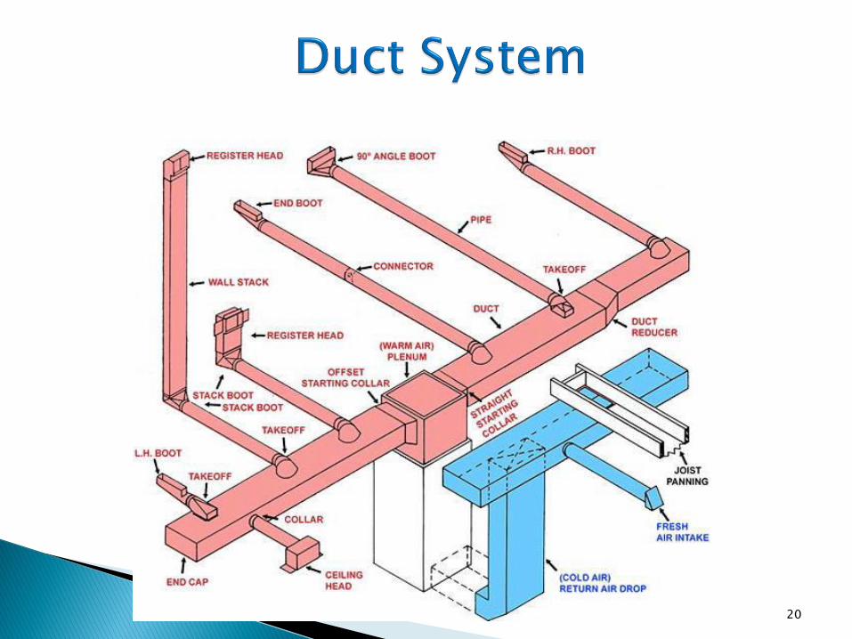
20
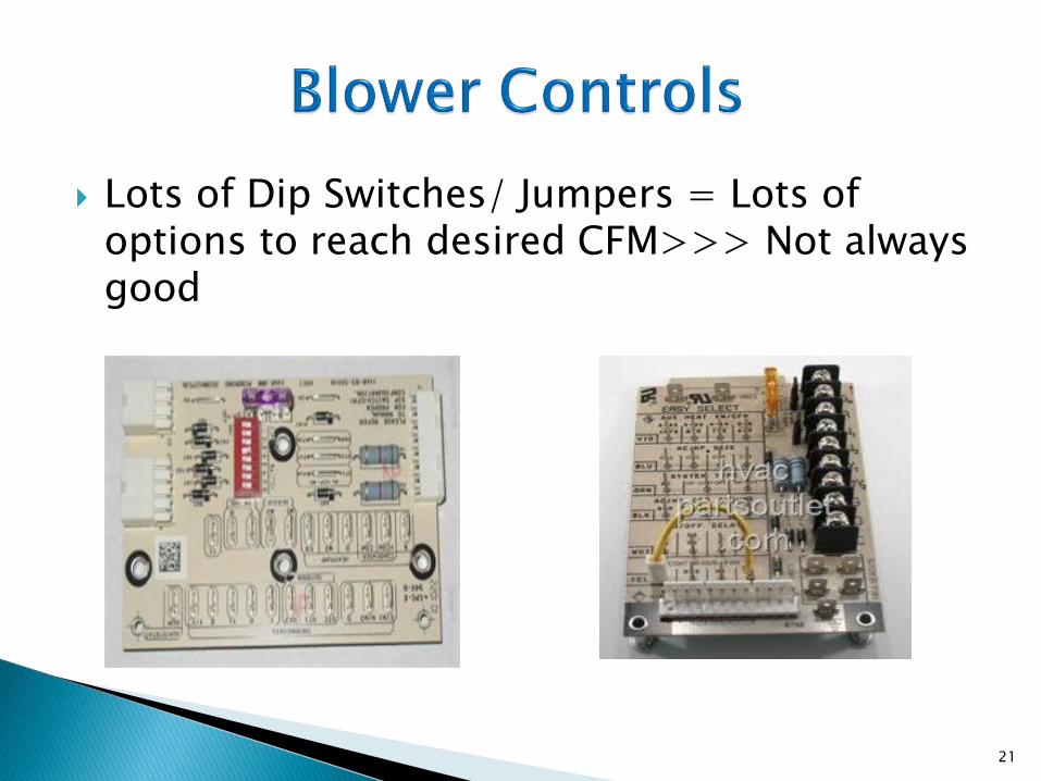
Lots of Dip Switches/ Jumpers = Lots of options to reach desired CFM>>> Not always good
21

Used to set blower speeds
In heat pump air handlers
Also Used to set blower speeds
In heat pump air handlers
22

No dip switches = not as many options to reach desired CFM>>> Not always good
Comfort setting = ◦ Maybe not enough CFM/Ton
◦ Could be more energy use
than a 60 watt light bulb
23

24

25
Modern heat pump air handler duct static pressure issues & the relationship of energy use to the ECM motors within those air handlers
26
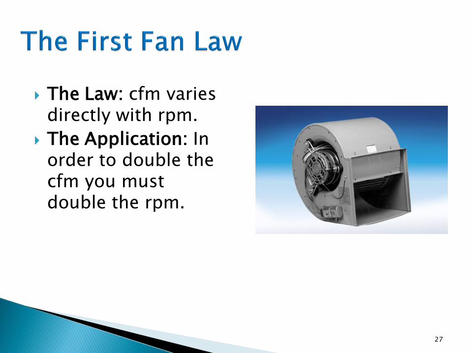
The Law: cfm varies directly with rpm.
The Application: In order to double the cfm you must double the rpm.
27

The Law: Static pressure capability varies as the square of the fan speed (rpm2).
The Application: If the fan speed or cfm is doubled, the resistance the fan has to operate against is four times as great.
If the speed is reduced by half, the static pressure is reduced to ¼.
.20
.80
28
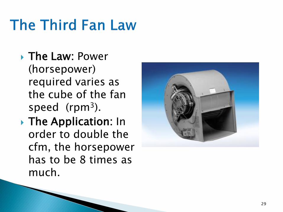
The Law: Power (horsepower) required varies as the cube of the fan speed (rpm3).
The Application: In order to double the cfm, the horsepower has to be 8 times as much.
29

A cubic foot of air per minute (CFM) has weight!
Air weighs .075 lbs/cubic foot
12
inches 12
inches
12
inches
800 CFM X .075 lbs/cubic foot =
60 lbs/minute
1000 CFM X 075 lbs/cubic foot =
75 lbs/minute
1200 CFM X . 075 lbs/cubic foot =
90 lbs/minute
30
31
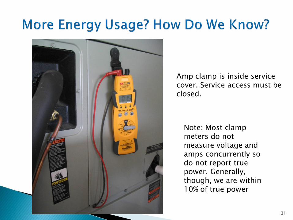
Amp clamp is inside service cover. Service access must be closed.
Note: Most clamp meters do not measure voltage and amps concurrently so do not report true power. Generally, though, we are within 10% of true power

The G2 Phoenix Clamp Meter Series™ The DL379Pro series offers the highest combination of functions, features, and safety offered in a meter today. Combined with The Hook extended clamp head, no contractor will have to compromise their safety, efficiency, or comfort. Features • Detachable clamp head • 750V AC / 1000V DC • 400A AC • 2000μA AC / DC • 40MΩ Resistance / Continuity • 4000μF Capacitance • -40 ~ 752°F Temperature (K type) • Frequency / Duty Cycle • µA for Flame Safeguard • Non-Contact Voltage • Diode • MIN / MAX display • Work light • Magnetic mount • Dual display with backlight • Test lead storage • Test lead holder on clamp head • Data hold • Auto off
32

In practical terms, the ampere is a measure of the amount of electric charge passing a point per unit
of time.
Multiplied by the Voltage applied to the device
equals WATTS
33
Remove the blower panel from air handler. Select button on meter to activate the Min/Max
display & clamp the Amp meter on the wire that is the input power to the blower motor, put blower panel back on air handler.
Raise the set temperature of the heat pump’s thermostat approximately 5-10 degrees above the room temperature.
We need to make sure that the system is working at full capacity, wait for any time delays programmed into the blower control board.
Record the Maximum Amp draw reading from the meter.
34

35
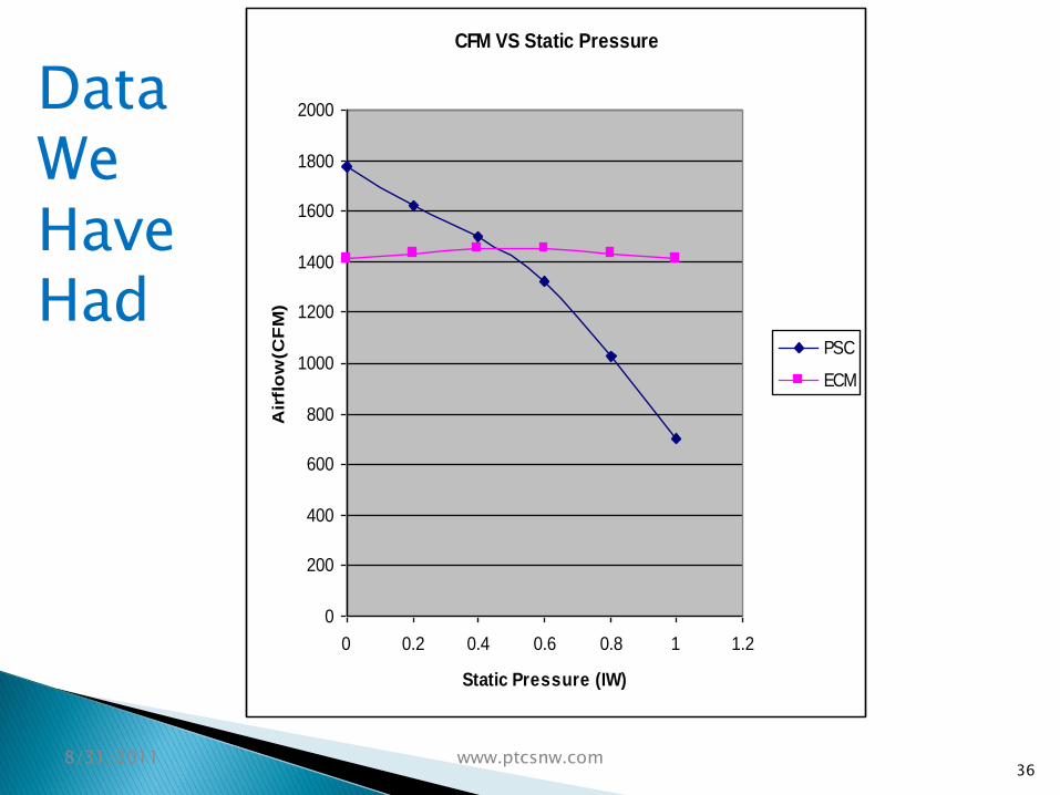
CFM VS Static Pressure
0
200
400
600
800
1000
1200
1400
1600
1800
2000
0 0.2 0.4 0.6 0.8 1 1.2
Static Pressure (IW)
Air
flo
w(C
FM
)
PSC
ECM
8/31/2011 www.ptcsnw.com
Data We Have Had
36
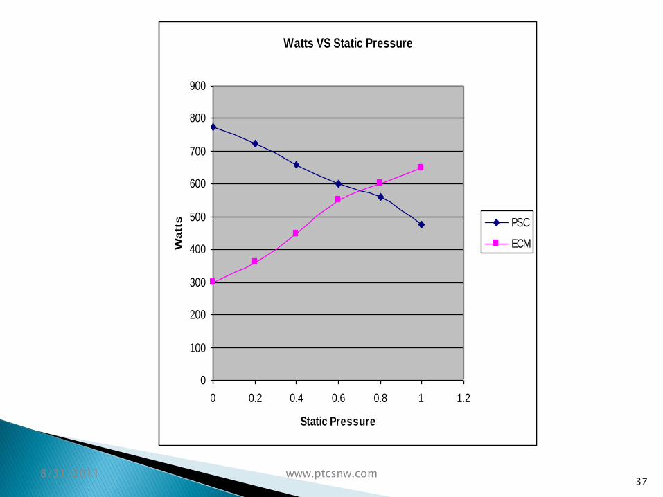
Watts VS Static Pressure
0
100
200
300
400
500
600
700
800
900
0 0.2 0.4 0.6 0.8 1 1.2
Static Pressure
Watt
s PSC
ECM
8/31/2011 www.ptcsnw.com 37
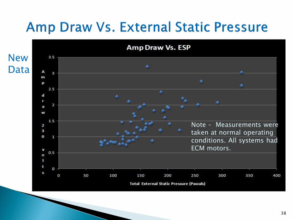
New Data
Note – Measurements were taken at normal operating conditions. All systems had ECM motors.
38
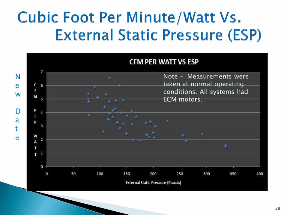
New Data
Note – Measurements were taken at normal operating conditions. All systems had ECM motors.
39

New Data Note – Measurements were
taken at normal operating conditions. This slide shows only ½ HP ECM motors.
40

New
Data
The “FAN ON” setting puts the fan in an ultra low flow mode so it will likely use 40-80 Watts. It will only kick up to the measured amps/watts when in heating/cooling mode.
41
NOTE: Air handler hours of use per year vary widely; On average, it may be lower.
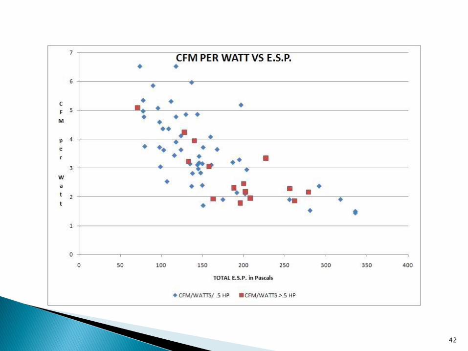
42

43

http://www.pwaengineering.com/power/
http://www.hatchell.com/files/ECM_Story.pdf
www.buildingscience.com/documents/published-articles/pa-ecm.../at.../file
This is the best article and backs up the findings made in this presentation.
44

Proper duct sizing that takes into account that the ECM blower motor must have a load or enough static pressure to be able to ramp (slowly speed up) to the desired RPM.
Both of issues 2 & 3 are due to high external static pressure. These issues are easy to correct with proper duct sizing.
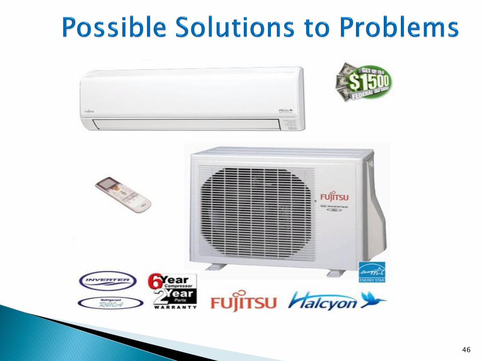
Possible Solutions to Problems
45
46

47

48

49
Engineered duct systems that take many inputs into account to determine the correct size of ducts in homes.
TEL-total equivalent length
ESP-external static pressure
Friction per 100’ of duct
Velocities in the trunk duct, branch ducts, and at registers & grills
Sound methods of duct sizing.
50
Do away with ducts or size them properly with proven methods. This is now more important than ever to ensure that heat pumps get the proper mass airflow across the coil and ECM motor energy use is low by design.
51

52


