HOW TO BUILD... A V1 LAUNCH SITE By Paul Davies Obviously there have been a few compromises with the model, most notably regarding the scaled down length of the launching ramp. The original Walter Schlitzrohrschleuder WR 2.3 catapult launch ramp has been quoted at anything from 36 - 58.4 metres long depending upon which source you consult. Assuming the longest dimension, then at 1/100th scale the model would be almost 24'' long, which would clearly dominate most wargames tables! The ramp sections supplied in ‘Open Fire’, make a ramp that is just under 6''. Unfortunately at the time of writing this ‘How to…’ there were no plans to separately release any of the plastic components from ‘Open Fire’, so if you want to create a longer ramp, or for that matter, have more of the very nice infantry figures you’ll need to get together with someone else and pool your resources. Anyway, for this ‘How to…’ I decided to create a selection of generic buildings associated with the early V1 launch sites. I stress ‘early’ because thanks to excellent Allied air reconnaissance and information from the resistance in Occupied Europe, the Germans quickly realised that they Some weeks ago, I was fortunate enough to get a sneak preview of the Flames Of War Open Fire boxed set when I was invited to the Wargames Illustrated 300th issue celebration, and was very impressed by the quality and amount of models and figures in the box. I was particularly interested in the V1, complete with launching ramp, and the possibilities for making it into something more than just a terrain piece or objective marker occurred to me immediately. needed to make the sites less obvious, particularly regarding the distinctive ‘ski’ building. GENERAL CONSTRUCTION I used Styrofoam® for the buildings in this ‘How to…’. It’s cheap, light and easy to cut with simple hand tools as long as you ensure that you use a sharp blade. Blunt blades will rip the foam, which will mean you’ll need to use filler to make good the damage. Be warned, that some fillers will attack the foam so always test fillers, glues and even paints, on a piece of waste material before using them! I experienced this problem during this project even though I was using a filler that I’d used before so, when opening a new tube or pack, my suggestion would be to test the contents before applying them to your precious model. As always, the plans are intended as a starting point and they should be scaled to suit your figures .net As with most of Paul Davies’ terrain building articles, you can find his plans ready for download at our website. Once downloaded you may need to rescale the plans to match the scale of your own project.
Transcript
How To Build...
a V1 launcH siTeBy Paul Davies
Obviously there have been a few compromises with the model, most notably regarding the scaled down length of the launching ramp. The original Walter Schlitzrohrschleuder WR 2.3 catapult launch ramp has been quoted at anything from 36 - 58.4 metres long depending upon which source you consult. Assuming the longest dimension, then at 1/100th scale the model would be almost 24'' long, which would clearly dominate most wargames tables! The ramp sections supplied in ‘Open Fire’, make a ramp that is just under 6''. Unfortunately at the time of writing this ‘How to…’ there were no plans to separately release any of the plastic components from ‘Open Fire’, so if you want to create a longer ramp, or for that matter, have more of the very nice infantry figures you’ll need to get together with someone else and pool your resources.
Anyway, for this ‘How to…’ I decided to create a selection of generic buildings associated with the early V1 launch sites. I stress ‘early’ because thanks to excellent Allied air reconnaissance and information from the resistance in Occupied Europe, the Germans quickly realised that they
Some weeks ago, I was fortunate enough to get a sneak preview of the Flames Of War Open Fire boxed set when I was invited to the Wargames Illustrated 300th issue celebration, and was very impressed by the quality and amount of models and figures in the box. I was particularly interested in the V1, complete with launching ramp, and the possibilities for making it into something more than just a terrain piece or objective marker occurred to me immediately.
needed to make the sites less obvious, particularly regarding the distinctive ‘ski’ building.
GENERAL CONSTRUCTION
I used Styrofoam® for the buildings in this ‘How to…’. It’s cheap, light and easy to cut with simple hand tools as long as you ensure that you use a sharp blade. Blunt blades will rip the foam, which will mean you’ll need to use filler to make good the damage. Be warned, that some
fillers will attack the foam so always test fillers, glues and even paints, on a piece of waste material before using them! I experienced this problem during this project even though I was using a filler that I’d used before so, when opening a new tube or pack, my suggestion would be to test the contents before applying them to your precious model.
As always, the plans are intended as a starting point and they should be scaled to suit your figures
.netAs with most of Paul Davies’ terrain building articles, you can find his plans ready for download at our website. Once downloaded you may need to rescale the plans to match the scale of your own project.
The launch ramp and catapult was usually protected by a wall each side of it, either made from bricks or concrete. My interpretation is based upon a wartime intelligence drawing (Zaloga, S J, German V-Weapon Sites 1943-45. Osprey Publishing, 2008).
Cut out all the components. Consult the exploded view below and you will see that the ends of certain components need to be cut at a 45o angle.
Pin and glue the components together.
Where parts 4 and 5 join you’ll need to trim the Styrofoam® slightly, because a cut made across an angle will be longer than one made at right angles to the edge.
Ideally I always leave the pins in place, simply pushing them right into the Styrofoam® to make a really strong joint, but you need to take care that your pins aren’t too long otherwise they’ll project through to the material.
I will cover painting in one section at the end of the article as it is basically the same for all the different constructions and there’s no point duplicating information. Similarly, I constructed some simple bases to go with each model, but the basic principles are the same for each one, so once again, I’ve slotted these in at the end of the article to avoid duplication.
These buildings varied in design; some looked like a basic pillbox; some, if time allowed, were built into the ground with the vision slot at ground level. Unless I’m building terrain for a particular game, perhaps for a wargame show, I avoid building terrain features or buildings into the terrain because it limits the playing options, so I chose the above-ground pillbox style because, if nothing else, I could use the building as a pillbox in another scenario. Incidentally a similar design of building was also used to store various V-1 related items including the warhead fuses which, understandably, needed to be stored safely well away from the warheads themselves!
Cut out the component parts. Pin and glue parts 2, 3 and 4 to the underside part 1 (the roof).
Pin and glue part 5 to part 6.
And then pin and glue the two assemblies together.
Finally trim back the sidewalls to match the roof.
The building needs a door, but it makes sense to add it after the building has been painted, so constructing the various doors for these models is covered at the end of the article.
Pain
tin
g &
M
od
elli
ng
THE LAUNCH RAMP
FIRE CONTROL LAUNCH BUNKER
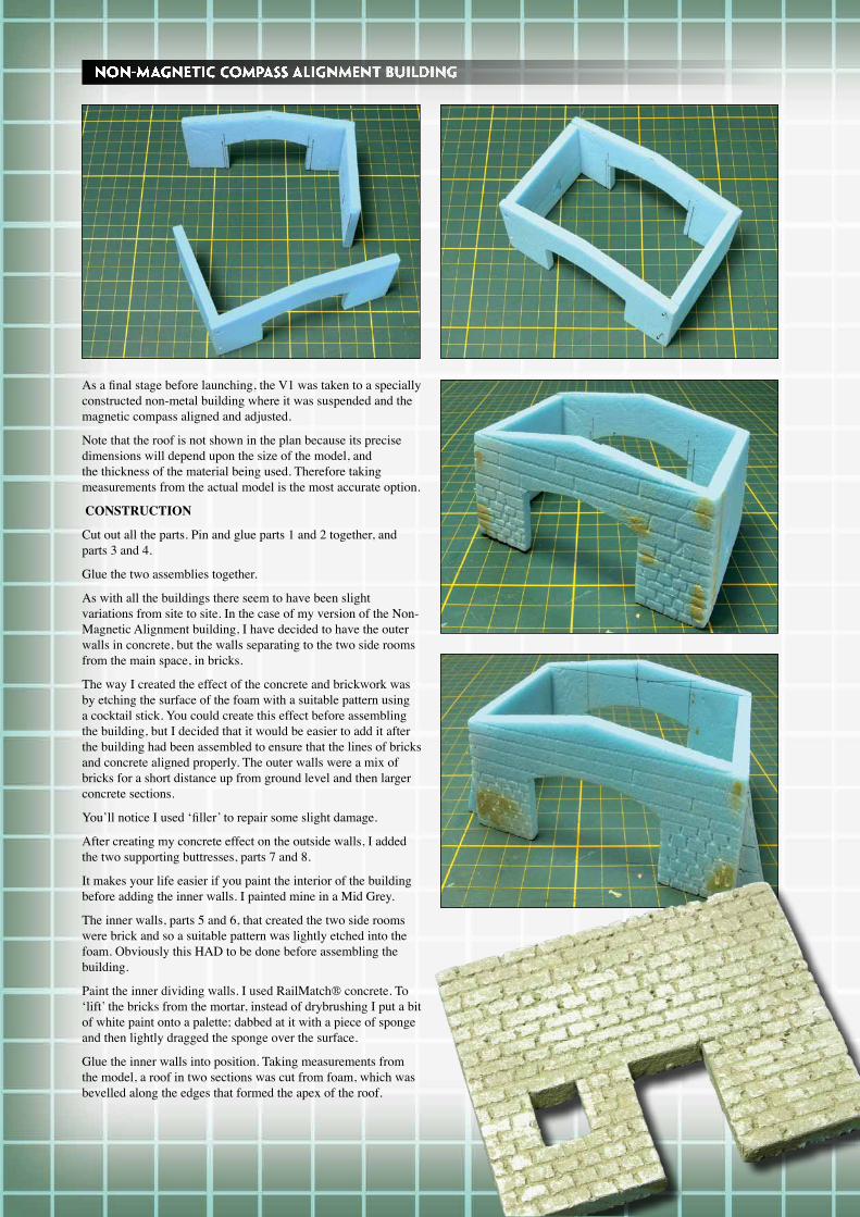
As a final stage before launching, the V1 was taken to a specially constructed non-metal building where it was suspended and the magnetic compass aligned and adjusted.
Note that the roof is not shown in the plan because its precise dimensions will depend upon the size of the model, and the thickness of the material being used. Therefore taking measurements from the actual model is the most accurate option.
CONSTRUCTION
Cut out all the parts. Pin and glue parts 1 and 2 together, and parts 3 and 4.
Glue the two assemblies together.
As with all the buildings there seem to have been slight variations from site to site. In the case of my version of the Non-Magnetic Alignment building, I have decided to have the outer walls in concrete, but the walls separating to the two side rooms from the main space, in bricks.
The way I created the effect of the concrete and brickwork was by etching the surface of the foam with a suitable pattern using a cocktail stick. You could create this effect before assembling the building, but I decided that it would be easier to add it after the building had been assembled to ensure that the lines of bricks and concrete aligned properly. The outer walls were a mix of bricks for a short distance up from ground level and then larger concrete sections.
You’ll notice I used ‘filler’ to repair some slight damage.
After creating my concrete effect on the outside walls, I added the two supporting buttresses, parts 7 and 8.
It makes your life easier if you paint the interior of the building before adding the inner walls. I painted mine in a Mid Grey.
The inner walls, parts 5 and 6, that created the two side rooms were brick and so a suitable pattern was lightly etched into the foam. Obviously this HAD to be done before assembling the building.
Paint the inner dividing walls. I used RailMatch® concrete. To ‘lift’ the bricks from the mortar, instead of drybrushing I put a bit of white paint onto a palette; dabbed at it with a piece of sponge and then lightly dragged the sponge over the surface.
Glue the inner walls into position. Taking measurements from the model, a roof in two sections was cut from foam, which was bevelled along the edges that formed the apex of the roof.
NON-MAGNETIC COMPASS ALIGNMENT BUILDING
Prior to launching, the V1’s were stored on trolleys, inside specially designed buildings. The Allies nicknamed them ‘ski’ buildings because of their distinctive shape, which from the air looked like a ski lying on its side. It was this easily spotted design, which made it easy for the Allied reconnaissance flights to identify the early V1 sites and was in turn, the reason why the Germans decided to resort to a less obvious building and site configuration, preferring instead to try to integrate their sites amongst existing farm buildings where possible. However there’s no doubt that the inclusion of a ‘ski’ building on your V1 site adds interest.
CONSTRUCTION
From various sources, including those credited at the end of this article, it was evident that the ‘curve’ of the ski could be in either direction.
Cut out and glue part 1 to part 2.
The two side walls are a little complicated as they incorporate a curve and it’s difficult to determine their length. My procedure was to first lay a piece of string along the length of part two and, allowing a couple of inches extra, cut out two strips of foam the same height as part 1.
The first step to bending the foam is to score a series of vertical lines partially through the material around the curve. I scored my lines 15mm apart. Start with the outer curve part 3, because it’s easiest as the curve is less sharp than the inner one.
Very carefully bend part 3 until it matches the curve of part 2, and then pin and glue it in place.
As a matter of interest, possibly for another project, if you’re really careful you can, following the above method, bend Styrofoam virtually back on itself!
Curving part 4 follows the same procedure as for part 3 except that, as the curve is tighter, the vertical score lines should be closer together; about 10mm worked well and the score cuts must be on the INSIDE of the curve. The other difference is that this wall includes a door. Carefully carry out a ‘dry-run’ and once you’re happy that the curve is good, cut out the door aperture, and then pin and glue the inner wall in position.
Cut out the end wall to fit between the sidewalls and pin and glue it in position. Trim off the excess walls.
Fill the ‘cracks’ where you made your scoring. It’s not really necessary to fill the ‘cracks’ on the inside of part 4, but it does add strength to the assembly which is always a good idea.
And that’s it for the basic constructions. The next step is painting the buildings.
THE ‘SKI’ BUILDING
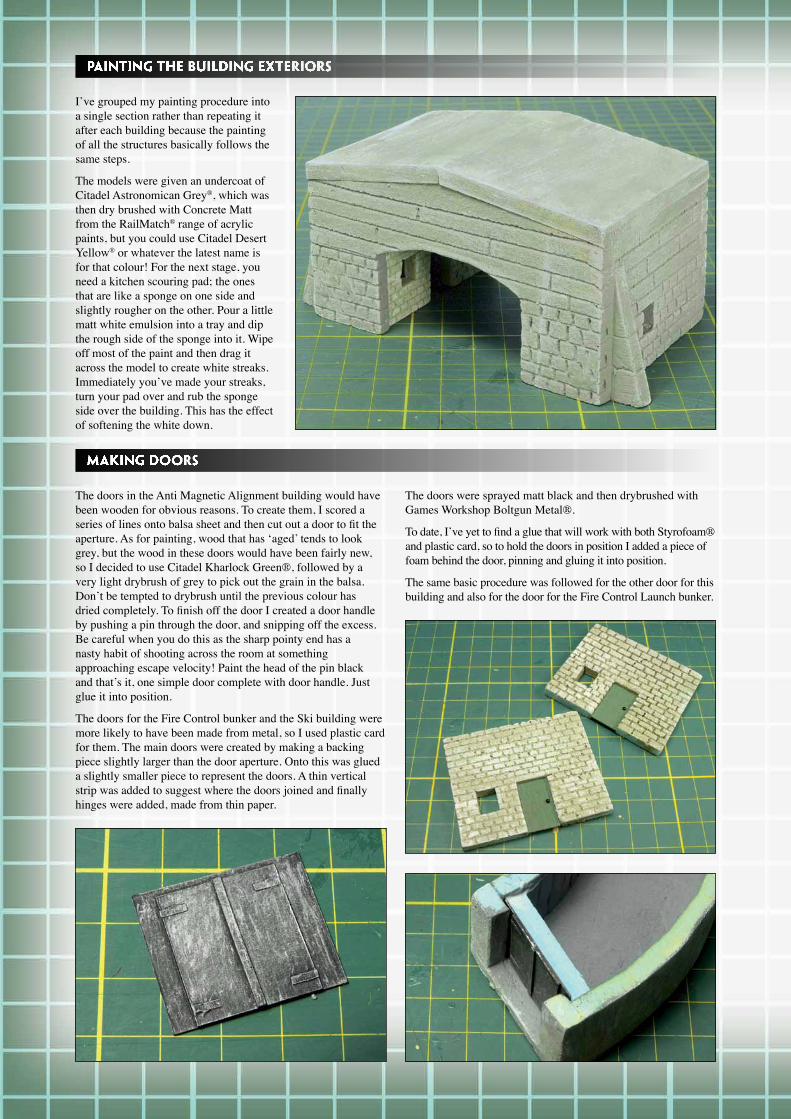
PAINTING THE BUILDING EXTERIORS
I’ve grouped my painting procedure into a single section rather than repeating it after each building because the painting of all the structures basically follows the same steps.
The models were given an undercoat of Citadel Astronomican Grey®, which was then dry brushed with Concrete Matt from the RailMatch® range of acrylic paints, but you could use Citadel Desert Yellow® or whatever the latest name is for that colour! For the next stage, you need a kitchen scouring pad; the ones that are like a sponge on one side and slightly rougher on the other. Pour a little matt white emulsion into a tray and dip the rough side of the sponge into it. Wipe off most of the paint and then drag it across the model to create white streaks. Immediately you’ve made your streaks, turn your pad over and rub the sponge side over the building. This has the effect of softening the white down.
MAKING DOORS
The doors in the Anti Magnetic Alignment building would have been wooden for obvious reasons. To create them, I scored a series of lines onto balsa sheet and then cut out a door to fit the aperture. As for painting, wood that has ‘aged’ tends to look grey, but the wood in these doors would have been fairly new, so I decided to use Citadel Kharlock Green®, followed by a very light drybrush of grey to pick out the grain in the balsa. Don’t be tempted to drybrush until the previous colour has dried completely. To finish off the door I created a door handle by pushing a pin through the door, and snipping off the excess. Be careful when you do this as the sharp pointy end has a nasty habit of shooting across the room at something approaching escape velocity! Paint the head of the pin black and that’s it, one simple door complete with door handle. Just glue it into position.
The doors for the Fire Control bunker and the Ski building were more likely to have been made from metal, so I used plastic card for them. The main doors were created by making a backing piece slightly larger than the door aperture. Onto this was glued a slightly smaller piece to represent the doors. A thin vertical strip was added to suggest where the doors joined and finally hinges were added, made from thin paper.
The doors were sprayed matt black and then drybrushed with Games Workshop Boltgun Metal®.
To date, I’ve yet to find a glue that will work with both Styrofoam® and plastic card, so to hold the doors in position I added a piece of foam behind the door, pinning and gluing it into position.
The same basic procedure was followed for the other door for this building and also for the door for the Fire Control Launch bunker.
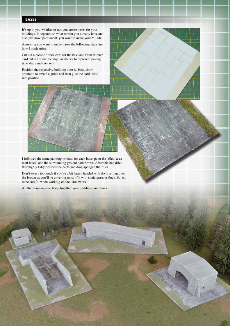
BASES
It’s up to you whether or not you create bases for your buildings. It depends on what terrain you already have and also just how ‘permanent’ you want to make your V1 site.
Assuming you want to make bases the following steps are how I made mine.
Cut out a piece of thick card for the base and from thinner card cut out some rectangular shapes to represent paving type slabs and concrete.
Position the respective building onto its base, draw around it to create a guide and then glue the card ‘tiles’ into position…
I followed the same painting process for each base; paint the ‘tiled’ area matt black, and the surrounding ground dark brown. After this had dried thoroughly I dry brushed the earth and drag-sponged the ‘tiles’.
Don’t worry too much if you’re a bit heavy handed with drybrushing over the brown as you’ll be covering most of it with static grass or flock, but try to be careful when working on the ‘stonework’.
All that remains is to bring together your buildings and bases…