16

How to design & develop an A.T.V
Part Chassis
The automotive chassis is tasked with holding all the components together while driving, and transferring vertical and lateral loads, caused by accelerations, on the chassis through the suspension and two the wheels. Most engineering students will have an understanding of forces and torques long before they read this. It is suggested that the reader has a good understanding of the concepts of axial forces, shear forces, bending, torsion, angular and normal deflections, and finally mass moment of inertia.
The key to good chassis design is that the further mass is away from the neutral axis the more rigid it will be.
This one sentence is the basis of automotive chassis design. Some people stress full triangulation and material choice but once you are into these specifics some critical understanding is missed. People familiar with space frames may be thinking that full triangulation is the key to a good space frame. While this will make the design better it can still benefit from this more general design principles. The design section of the book will talk more about these items in relation to the types of chassis but the first part is the theory.
Tubular Space frame :-
Considered to be one of the best chassis methods that can yeild very good results for torsion rigidity, weight holding, and impact protection it is also simple to design and only moderate in difficulty to build. This makes it perfect for many applications from ATV cars to project cars and even low volume sports cars. Anyone who has ever designed a space frame will know that triangulation isvery important as well as making sure that it is comprised of nodes where the tube ends meet and not to have parts subjected to bending loads. This seems like a tall order but the first thing to understand is that even though these aspects are important it is still subjected to tubular theory that was presented earlier. Therefore making it as wide as possible with make the chassis more rigid. This is normally difficult to do but through making side pods structural it is possible to add strength. The biggest problem of any design is that it will require openings for entry and exit from the cockpit area and these will not be filly triangulated. This will be the weak spot for the chassis and care must be taken to ensure this area is of sufficient strength.
As ladder chassis is not strong enough, motor racing engineers developed a 3 dimensional design - Tubular space frame. One of the earliest examples was
How to design & develop an A.T.V
the post-war Maserati Typo 61 "Birdcage" racing car. Tubular space frame chassis employs dozens of circular-section tubes (some may use square-section tubes for easier connection to the body panels, though circular section provides the maximum strength), position in different directions to provide mechanical strength against forces from anywhere. These tubes are welded together and forms a very complex structure, as you can see in the below pictures.
Advantages:-Very strong in any direction. (compare with ladder chassis and Monocoque chassis of the same weight)
Disadvantages:-Very complex, costly and time consuming to be built. Impossible for robotized production. Besides, it engages a lot of space raise the door sill and result in difficult access to the cabin.
Who uses it:- All Ferrari Before the 360M, Lamborghini, Diablo, Jaguar XJ220, Caterham and ATV cars.
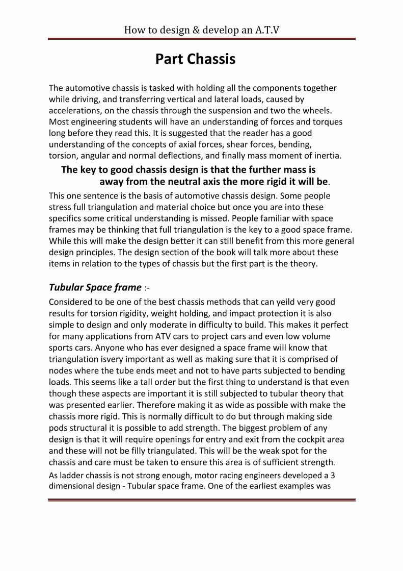
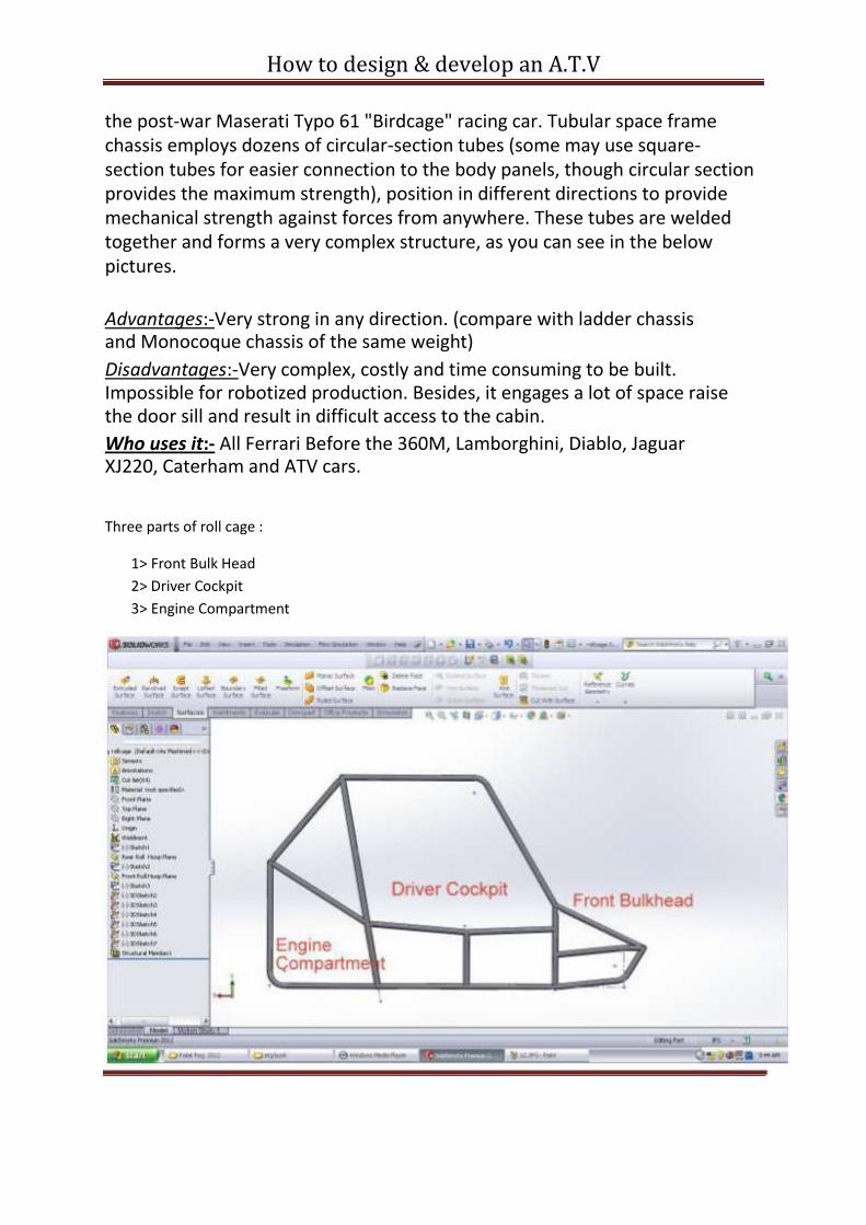
Three parts of roll cage :
1> Front Bulk Head
2> Driver Cockpit
3> Engine Compartment
How to design & develop an A.T.V
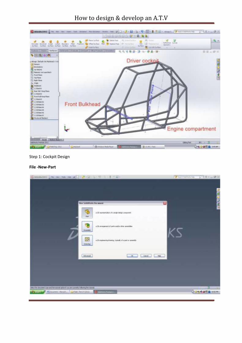
Step 1: Cockpit Design
File -New-Part
How to design & develop an A.T.V
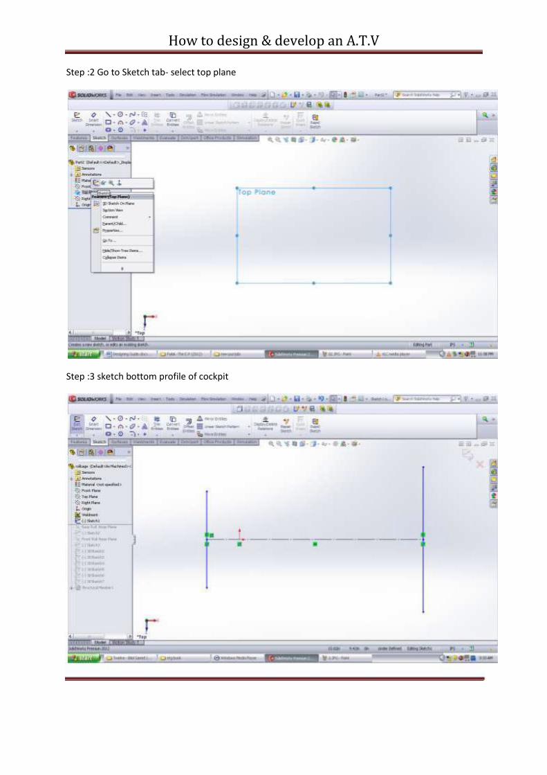
Step :2 Go to Sketch tab- select top plane
Step :3 sketch bottom profile of cockpit
How to design & develop an A.T.V
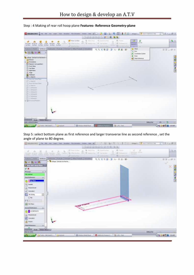
Step : 4 Making of rear roll hoop plane Features- Reference Geometry-plane
Step 5: select bottom plane as first reference and larger transverse line as second reference , set the angle of plane to 80 degree.

How to design & develop an A.T.V
Step 6 : right click on new created rear roll hoop plane and click sketch , sketch the rear roll hoop with required dimension .
Step 7 : Drawing Front roll hoop plane Features-Reference Geometry-plane . Take bottom plane as first reference and shorter transverse line as second reference.
How to design & develop an A.T.V
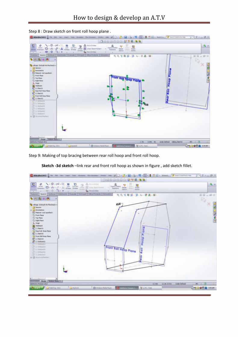
Step 8 : Draw sketch on front roll hoop plane .
Step 9: Making of top bracing between rear roll hoop and front roll hoop.
Sketch -3d sketch –link rear and front roll hoop as shown in figure , add sketch fillet.
How to design & develop an A.T.V
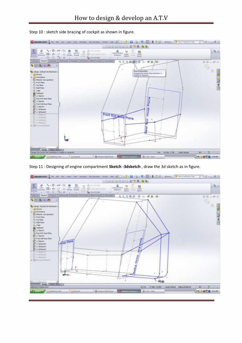
Step 10 : sketch side bracing of cockpit as shown in figure.
Step 11 : Designing of engine compartment Sketch -3dsketch , draw the 3d sketch as in figure.
How to design & develop an A.T.V
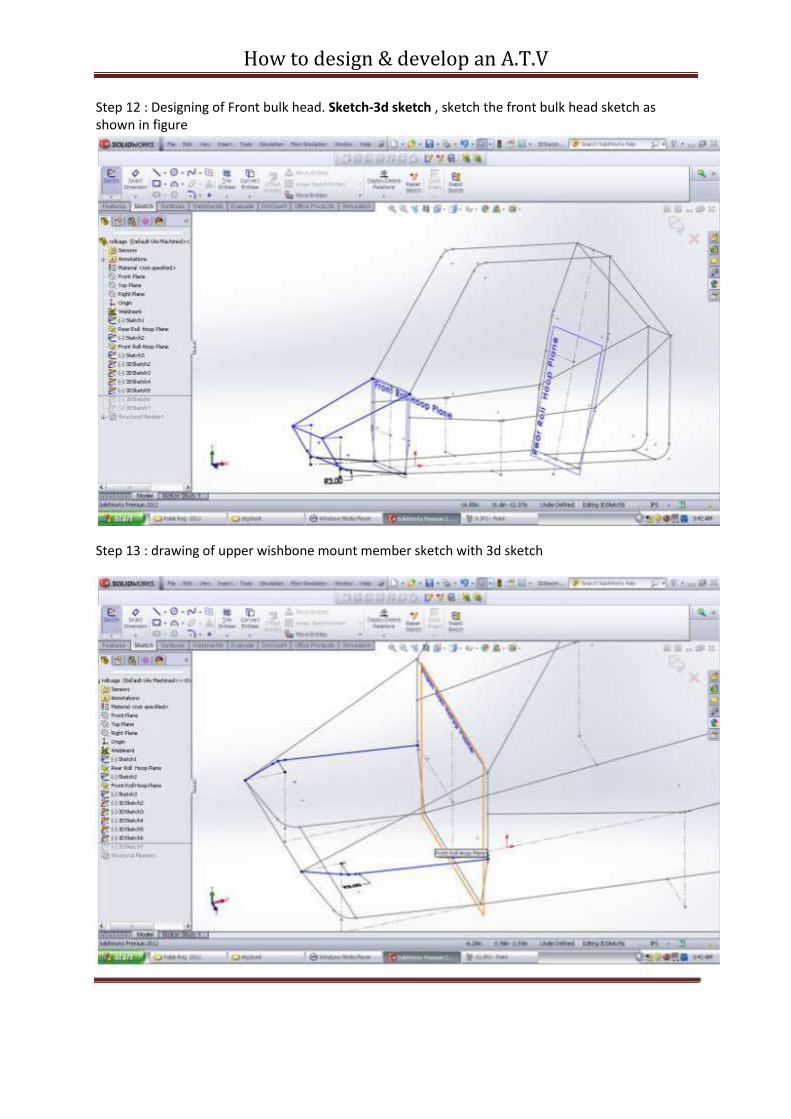
Step 12 : Designing of Front bulk head. Sketch-3d sketch , sketch the front bulk head sketch as shown in figure
Step 13 : drawing of upper wishbone mount member sketch with 3d sketch
How to design & develop an A.T.V
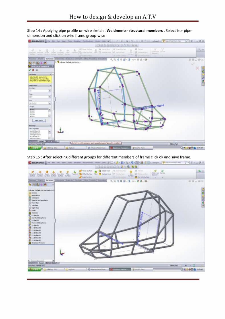
Step 14 : Applying pipe profile on wire sketch . Weldments- structural members . Select iso- pipe-dimension and click on wire frame group-wise
Step 15 : After selecting different groups for different members of frame click ok and save frame.
How to design & develop an A.T.V
Roll cage Analysis
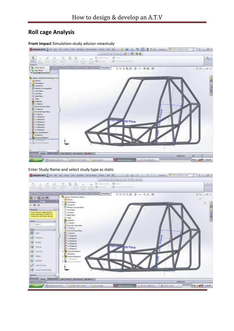
Front Impact Simulation-study advisor-newstudy
Enter Study Name and select study type as static
How to design & develop an A.T.V
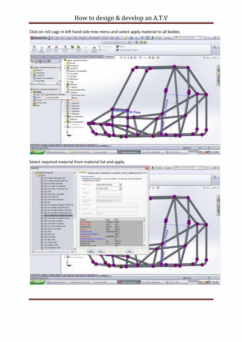
Click on roll cage in left hand side tree menu and select apply material to all bodies
Select required material from material list and apply
How to design & develop an A.T.V
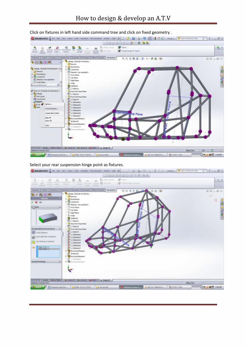
Click on fixtures in left hand side command tree and click on fixed geometry .
Select your rear suspension hinge point as fixtures.
How to design & develop an A.T.V
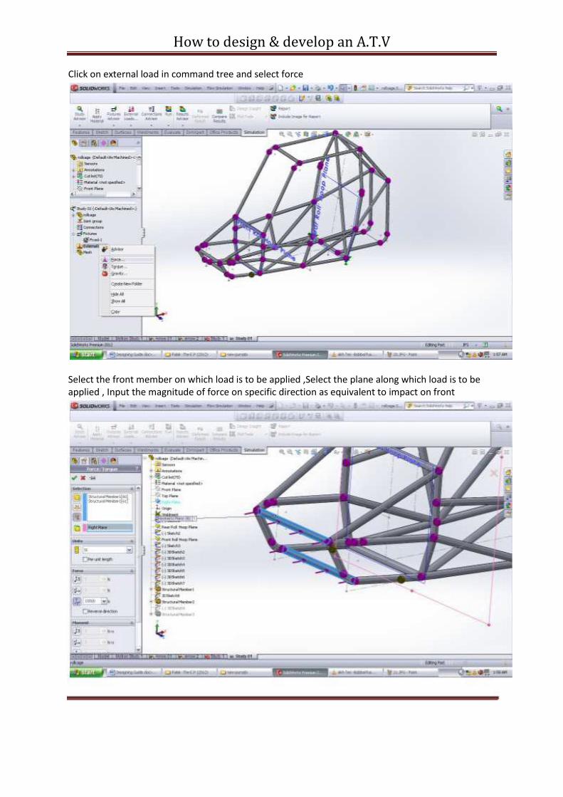
Click on external load in command tree and select force
Select the front member on which load is to be applied ,Select the plane along which load is to be applied , Input the magnitude of force on specific direction as equivalent to impact on front
How to design & develop an A.T.V
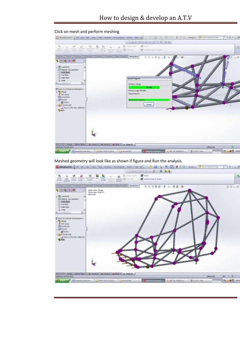
Click on mesh and perform meshing
Meshed geometry will look like as shown if figure and Run the analysis.


