1 Introduction 1.1 Purpose This application note introduces a general procedure of how to enable standard Linux BSP L5.4 on a new customized i.MX8/8X board. This document can help users, who have designed a customized i.MX8/8X board, to quickly port standard Linux BSP release code running on their board and be aware of those key parts that need modifications. 1.2 Example board This application note uses an i.MX8QXP reference board for automotive as an example board, because this board is not supported by the standard Linux BSP release. For more details, contact NXP representative. The board’s hardware design is based on i.MX8QXP MEK board, but with the following changes: • i.MX8QXP C0 Silicon • Samsung auto LPDDR4 and eMMC5.1 • MIPI-CSI with NVP6324 automotive AHD solution • LVDS display with TI DS90UB947/948 Serdes (through FPD-Link III) for automotive application • MIPI-DSI display with Maxim 96752/96755 Serdes (through GMSL2) for automotive application • NXP TJA1101 automotive 100Mbps Ethernet PHY • USB3.0 host for Carplay/AA and USB2.0 OTG for debug Contents 1 Introduction......................................1 1.1 Purpose........................................1 1.2 Example board............................. 1 1.3 Linux BSP releases..................... 2 2 Generating DDR configuration files ........................................................ 2 2.1 Downloading RPA tools............... 3 2.2 Using RPA tools........................... 3 3 SCFW porting.................................. 6 3.1 Extracting SCFW code.................6 3.2 Creating a new board file............. 6 3.3 Compiling SCFW....................... 10 4 Running a DDR stress test............ 11 5 ATF porting....................................13 5.1 Power management................... 14 5.2 Resource partitioning................. 15 5.3 Compiling ATF........................... 17 6 U-Boot porting............................... 17 6.1 Creating files for a new board.... 17 6.2 Modifying files for a new board.. 18 6.3 Compiling U-Boot....................... 21 7 Building flash.bin image................ 22 7.1 Copying images to mkimage..... 22 7.2 Checking makefile......................22 7.3 Generating flash.bin image........ 26 7.4 Burning flash.bin images........... 27 8 Linux kernel porting....................... 27 8.1 Creating files for a new board.... 27 8.2 Modifying files for new board..... 29 8.3 Compiling Linux Kernel.............. 32 8.4 Burning Linux Kernel................. 32 9 Revision history............................. 32 AN13275 How to Enable Linux BSP L5.4 on a New iMX8/8X Board Rev. 0 — 10 June, 2021 Application Note
Transcript
1 Introduction
1.1 PurposeThis application note introduces a general procedure of how to enable standardLinux BSP L5.4 on a new customized i.MX8/8X board. This document canhelp users, who have designed a customized i.MX8/8X board, to quickly portstandard Linux BSP release code running on their board and be aware of thosekey parts that need modifications.
1.2 Example boardThis application note uses an i.MX8QXP reference board for automotive as anexample board, because this board is not supported by the standard Linux BSPrelease. For more details, contact NXP representative.
The board’s hardware design is based on i.MX8QXP MEK board, but with thefollowing changes:
• i.MX8QXP C0 Silicon
• Samsung auto LPDDR4 and eMMC5.1
• MIPI-CSI with NVP6324 automotive AHD solution
• LVDS display with TI DS90UB947/948 Serdes (through FPD-Link III) forautomotive application
• USB3.0 host for Carplay/AA and USB2.0 OTG for debug
Contents
1 Introduction......................................11.1 Purpose........................................11.2 Example board.............................11.3 Linux BSP releases..................... 22 Generating DDR configuration files
........................................................ 22.1 Downloading RPA tools............... 32.2 Using RPA tools...........................33 SCFW porting..................................63.1 Extracting SCFW code.................63.2 Creating a new board file.............63.3 Compiling SCFW....................... 104 Running a DDR stress test............115 ATF porting....................................135.1 Power management...................145.2 Resource partitioning.................155.3 Compiling ATF........................... 176 U-Boot porting............................... 176.1 Creating files for a new board....176.2 Modifying files for a new board.. 186.3 Compiling U-Boot.......................217 Building flash.bin image................ 227.1 Copying images to mkimage..... 227.2 Checking makefile......................227.3 Generating flash.bin image........267.4 Burning flash.bin images........... 278 Linux kernel porting.......................278.1 Creating files for a new board....278.2 Modifying files for new board..... 298.3 Compiling Linux Kernel..............328.4 Burning Linux Kernel................. 329 Revision history.............................32
AN13275How to Enable Linux BSP L5.4 on a New iMX8/8X BoardRev. 0 — 10 June, 2021 Application Note
Figure 1. i.MX8QXP reference board for automotive
1.3 Linux BSP releasesThis application note uses the L5.4.47_2.2.0 Linux BSP release as example. For all i.MX Linux BSP releases, see EmbeddedLinux for i.MX Applications Processors.
The following chapters introduce the general procedure for porting SCFW, ATF, U-Boot and Linux Kernel. Each of them can becompiled independently, and the release package or source code can be downloaded from following links:
2 Generating DDR configuration filesThe i.MX 8/8X DDR Register Programming Aid (RPA) is an Excel spreadsheet tool used to develop DDR initialization for a user’sspecific DDR configuration (DDR device type, density, etc.). The RPA generates the DDR initialization in two formats (in separateExcel worksheet tabs):
This format is used specifically with the DDR stress test by first copying the contents on the DDR Stress Test Script CBTtab and then pasting it to a text file, naming the document with the .ds file extension. Use this file when executing the DDRstress test.
• DCD CFG file
This format is the configuration file used specifically by the SCU Firmware (SCFW). In this scenario, the user copies thecontents on the DCD CFG file CBT tab and pastes it to a text file, naming the document with the .cfg file extension and placingthis file in the appropriate SCFW board file directory.
2.1 Downloading RPA tools
In all cases, the RPA revision is aligned to a minimum SCFW version as shown in the table on i.MX 8/8X FamilyDDR Tools Release. In some cases, the BSP alignment is provided as extra details.
NOTE
To obtain the latest RPAs, see the following links:
• i.MX8QM DDR Register Programming Aid (RPA)
• i.MX8QXP/DXP/DX DDR Register Programming Aid (RPA)
To align with the L5.4.47_2.2.0 BSP and SCFW 1.6.0, use MX8QXP_C0_B0_LPDDR4_RPA_1.2GHz_v14.xlsx RPA version in thebelow steps.
2.2 Using RPA toolsTo use RPA tools to generate a new DDR stress test script and DCD CFG file for the specific DDR on user’s customized board,perform the following steps.
1. Obtain the desired DDR datasheet from the DDR vendor
To fill the DRAM parameters in the RPA tools, use the DDR datasheet from the DDR vendor. Usually this datasheet canbe downloaded from DDR vendor’s website. Users can also contact DDR vendor directly to request this datasheet.
2. Update the Device Information table on the Register Configuration tab
In the Device information table highlighted in Figure 2, update the following information:
• Manufacturer
• Memory part number
• Density per channel per chip select (Gb)
• Number of Chip Selects used
• Number of ROW Addresses
• Number of COLUMN Addresses
• Number of BANK addresses
• Bus Width
• Clock Cycle Freq (MHz)
Other parameters will be automatically calculated and filled in the table using the information above.
3. Update data bus mapping on the BoardDataBusConfig tab
Figure 3. i.MX8QXP RPA tool BoardDataBusConfig
Usually the physical connection of data pins between DDR device and SOC is not a direct match due to physical layoutconstraint. Therefore we need a mapping table to record the physical connection of DDR data pins, and put this informationinto DDR controller’s register, so that it can make correct logic connections of DDR data pins.
In the row highlighted in Figure 3, update the physical mapping of data pins between DDR device and SOC, according totheir hardware schematic. Other parameters will be updated automatically according to user’s input.
For example, from the example board schematic in Figure 4, we can find that the DQ0_A pin on DDR devices is connectedto DDR_DQ13 pin on iMX8QXP, so we type 13 in the circled cell and for others, follow the same method.
How to Enable Linux BSP L5.4 on a New iMX8/8X Board, Rev. 0, 10 June, 2021Application Note 4 / 33
Figure 4. Connection of DDR data pins in example board schematic
4. Copy text on the DCD CFG file CBT and DDR Stress Test Script CBT tabs to file
Click the DCD CFG file CBT tab in RPA tool and copy all the text into a file, naming it as BOARD_NAME.cfg. This file willbe used later when porting SCFW.
Click the DDR Stress Test Script CBT tab and copy all the text into a file, naming it as BOARD_NAME.ds. This file will beused in the DDR stress test later.
How to Enable Linux BSP L5.4 on a New iMX8/8X Board, Rev. 0, 10 June, 2021Application Note 5 / 33
3 SCFW portingThe System Controller Unit (SCU) provides an abstraction to many underlying features of the hardware. The software running onSCU is known as SC firmware (SCFW). SCFW provides the following features and services.
• System Initialization and Boot
• System Controller Communication
• Power Management
• Resource Management
• Pad Configuration
• Timers
• Interrupts
• Security
• Miscellaneous
Most SCFW codes are provided only in the object file format in SCFW porting kit and cannot be modified by users. But for boardrelated settings, SCFW porting kit has provided the source code of board.c file, which includes board related initialization functionsand customized features. This chapter focuses on how to port the board.c file for a new board.
3.1 Extracting SCFW codeTo extract SCFW code, perform the following steps.
1. Download the SCFW 1.6.0 package, imx-scfw-porting-kit-1.6.0.tar.gz, from Apps.
5. After reading and accepting the license, extract the SCFW code in the imx-scfw-porting-kit-1.6.0 folder. Besides the code,there are release documents extracted in the imx-scfw-porting-kit-1.6.0/doc/pdf folder, including release note, api userguide and a more detailed porting guide. For new users and developers of i.MX8/8X product, these documents are veryuseful. It’s highly recommended to check these documents first when you have questions about SCFW.
6. Use the following command to extract SCFW code specific for i.MX8QXP.
The code is in the path of imx-scfw-porting-kit-1.6.0/src/scfw_export_mx8qx_b0/.
We can set this path as SCFW_DIR.
3.2 Creating a new board fileEach board has its own special hardware design and may have different board operations in SCFW level. Therefore SCFWprovides a board folder under SCFW_DIR/platform/board/ for every supported board.
NXP SemiconductorsSCFW porting
How to Enable Linux BSP L5.4 on a New iMX8/8X Board, Rev. 0, 10 June, 2021Application Note 6 / 33
• board.h: The header file of board.c, including macro definitions used in board.c
• Makefile: The makefile for compiling of board.c
• dcd/: The folder of DDR configuration files, usually containing at least two scripts as below:
— ddr_stress_test_parser.cfg: Used for compiling SCFW for DDR stress test.
— BOARD_NAME.cfg: The ddr script generated in Using RPA tools and used for compiling SCFW for the normal systemuse.
To simplify the porting effort, users can directly copy those files from the reference board folder, mx8qx_mek, and makemodifications according to their own specific requirement.
Since the modification is highly related to board design and the final product’s use case, this document does not list detailedmodifications but the following three examples that often need customization in user’s own board.c file.
1. In the board_system_config() function
One major feature that the SCFW provides is resource partitioning. It partitions resources into different domains to protectsystem. By default, we will create a partition for the M4 core, performed in the board_system_config() in board.c.
In general, the resource partitioning of M4 follows these steps:
a. Mark all resources as not movable.
b. Create a new partition for M4 core.
c. Mark all resources and pad that belong to M4 subsystem as movable.
d. Mark resources and pad that M4 core need to use as movable.
Usually this part need modification according to board design and use case.
NXP SemiconductorsSCFW porting
How to Enable Linux BSP L5.4 on a New iMX8/8X Board, Rev. 0, 10 June, 2021Application Note 7 / 33
e. Move all resources and pads that have been marked as movable to M4 partition.
f. Assign memory region for M4 partition.
Usually the memory region in DDR need to be adjusted according to board’s DRAM size.
g. Grant permissions for other partitions to access M4’s resources.
This part can also be customized depending on use case.
NXP SemiconductorsSCFW porting
How to Enable Linux BSP L5.4 on a New iMX8/8X Board, Rev. 0, 10 June, 2021Application Note 8 / 33
For the detailed descriptions of the SCFW API used above, see Chapter 16 in sc_fw_port.pdf.
2. In the board_ioctl() function
In certain use case, users may need to add their own board level function or feature implementation in SCFW. Theboard_ioctl() function in board.c is a good place to do so.
Use the SCFW API, sc_misc_board_ioctl, from Linux or M4 to get into board_ioctl() function in board.c.
The sc_misc_board_ioctl() function is passed almost directly to the board_ioctl() function. Three parameters arepassed and returned by pointer and an error code is returned. Users can define meaning for these three parameters, andimplement their own features in the board_ioctl() function. This call is not associated to any resource so there is nosecurity. The MU the API call came from is passed in and the partition number that owns that MU is also passed in. Thesecan be used to implement some kind of security.
3. In the board_parameter() function
The board_parameter() function in board.c, as its name implies, is used for configuring board level parameters. Itincludes PCIe PLL clock source, settings for KS1 mode and spread spectrum feature for display.
Modify the return value for each parameter to choose desired configuration for their board. For example, to use externalclock as PCIe PLL’s source clock, set board_parameter() as below:
NXP SemiconductorsSCFW porting
How to Enable Linux BSP L5.4 on a New iMX8/8X Board, Rev. 0, 10 June, 2021Application Note 9 / 33
To use internal clock as PCIe PLL’s source clock, set board_parameter() as below:
For all available parameter settings, see Chapter 4.4.1 Board Parameters in sc_fw_port.pdf, or the header file inSCFW_DIR/platform/main/board.h.
3.3 Compiling SCFWTo compile SCFW, perform the following steps:
1. Set building environment
SCFW builds are compiled with a cross compiler in Linux environment. The toolchain for compiling should be obtained fromGNU Arm Embedded Toolchain Downloads. The version used is the GNU Arm Embedded Toolchain: 8-2018-q4-majorDecember 20, 2018. Please download the toolchain source and follow instructions to install the toolchain on the hostLinux machine.
After the installation, the environment variable, TOOLS, needs to be set to the directory containing the compiler directory.For example, if using the GCC 4.9 cross-compile tools chain and installing to /home/example/gcc-arm-none-eabi-8-2018-q4-major, set TOOLS to /home/example. Building also requires srec_cat, usually found in the Linux srecord package.Optionally the cppcheck package is also useful.
If using bash, then set the TOOLS environment variable as follows:
$export TOOLS=<your path to dir holding the toolchain>
2. Compile the code
The SC firmware can be fully compiled using the Makefile. The command format is:
Usage: make TARGET OPTIONS
SCFW targets are based on the die, not the part number. Some parts are phantoms of other die (for example QP is aphantom of QM) created by fusing options. Phantoms are supported at run-time by the SCFW reading the fuses andadapting. There are three primary die targets:
• qm : i.MX8QM die
• qx : i.MX8QX die
• dxl : i.MX8DXL die
They generate the image (scfw_tcm.bin) in their respective build directory.
Table 1 lists options that can be specified on the make command line.
Table 1. Options on make command line
Option Action
V=0 quiet output (default)
V=1 verbose output
D=0 configure for no debug
D=1 configure for debug (default)
DL=<level> configure debug level (0-5)
Table continues on the next page...
NXP SemiconductorsSCFW porting
How to Enable Linux BSP L5.4 on a New iMX8/8X Board, Rev. 0, 10 June, 2021Application Note 10 / 33
This application note uses an i.MX8QXP board for automotive as an example board, so the board folder name ismx8qx_auto and DDR script name is imx8qxp_auto_samsung3GB_1.2GHz_v14.cfg. The compile command is:
For MX8QX, the R=b0 applies to both B0 and C0 silicon revisions. In other words, even if you are building for andusing C0 silicon, you will still need to use R=b0.
NOTE
If the compilation is successful, the SCFW binary can be found in the path of SCFW_DIR/build_mx8qx_b0/scfw_tcm.bin.
For DDR stress test in Running a DDR stress test, an SCFW with special DDR scriptddr_stress_test_parser.cfg is needed. Therefore, besides the standard SCFW, users also need to compilea special SCFW for DDR stress test with following command:
4 Running a DDR stress testMX8 DDR stress test is a software application to verify DDR interface on i.MX8 series boards. It is a program running on the PCside which downloads a test image to the i.MX series processor’s internal RAM through a USB connection. Because it needs toaccess Windows Registry, user must run it in administrator mode. The test image running on the target board executes the DDRstress test. The result is sent to the PC via the A-core UART and is displayed in the log window. There is also an option to savethe output to a log file.
MX8 DDR Stress Test can help verify DDR stability on the board in a non-OS environment.
To run the DDR Stress Test Tool, perform the following steps:
1. Download the DDR stress test tool from i.MX 8/8X Family DDR Tools Release.
After being downloaded and installed, the tool can be found in the mx8_ddr_stress_test_ER14 folder under the install path.
For more details about DDR stress test tool, see MX8_DDR_Tool_User_Guide.pdf.
NXP SemiconductorsRunning a DDR stress test
How to Enable Linux BSP L5.4 on a New iMX8/8X Board, Rev. 0, 10 June, 2021Application Note 11 / 33
This file is generated in Step 4. In this case, the DDR script’s name is imx8qxp_auto_board.ds and the file can be putin the mx8_ddr_stress_test_ER14\script\mx8qx\imx8qxp_auto_board.ds folder.
• The special SCFW
This file is generated in Compiling SCFW, with DDR script, ddr_stress_test_parser.cfg. Rename theSCFW binary file from scfw_tcm.bin to mx8qxb0_scfw_download.bin and replace the file in the toolfolder, mx8_ddr_stress_test_ER14\bin\mx8qxb0_scfw_download.bin.
For MX8QX, this name applies to both B0 and C0 silicon revisions. In other words, even if you are building for andusing C0 silicon, you will still need to re-name the scfw_tcm.bin as mx8qxb0_scfw_download.bin.
NOTE
3. Connect the target board to PC host.
a. Configure the i.MX target board to boot in Serial Download mode/Manufacture mode and power up the board.
b. Connect a UART cable from the host computer to the MX8 debug UART. Please note that for Win10, may requiremanually installing COM port driver (FTDI, SiLabs,…)
c. Connect a USB cable from the host computer to the USB OTG port on the MX8 target board. A HID-compliantdevice or USB Input Device will be shown in the Device Manager. Please note that for the MX8 USB OTGconnection, the USB cable must be connected directly to the Host PC USB port and not through a USB HUB.
4. Launch the MX8_DDR_Tester.exe in the tool folder.
NXP SemiconductorsRunning a DDR stress test
How to Enable Linux BSP L5.4 on a New iMX8/8X Board, Rev. 0, 10 June, 2021Application Note 12 / 33
For Win10, right click on MX8_DDR_Tester.exe and select Run as administrator to view and select the availableCOM ports.
NOTE
5. Press the Search button in the Debug UART area, choose the correct UART port connected to the MX8 Cortex A-CoreDebug UART and press the Connect button.
To view and select the available COM port, run the DDR stress test in administrator mode.
NOTE
6. Load DDR initialization script and choose correct downloading options.
In this example, we choose the script in the path of mx8_ddr_stress_test_ER14\script\mx8qx\imx8qxp_auto_board.ds.
7. Press the Download button and wait for target board to be ready.
If the target board boots successfully, DDR initialization information is present on the tool’s console.
8. Press the Stress Test button, with all default settings: default DDR frequency, cache enabled, one loop DDR stress test,stop when encounter error.
If the board passes the DDR stress test successfully, the Success: DDR Stress test completed!!! log is shown as below:
9. Select Over Night Test, press the Stress Test button again, and the infinite loop of DDR stress test starts. Usually inorder to increase the confidence on the DDR stability, the board need to pass DDR stress test for more than 12 hoursand may need to repeat the same test in high/low temperature.
5 ATF portingArm Trusted Firmware is a reference implementation of secure world software for Arm A-Profile architectures (Armv8-A andArmv7-A), including an Exception Level 3 (EL3) Secure Monitor. It provides a suitable starting point for production of secure worldboot and runtime firmware, in either the AArch32 or AArch64 execution states.
ATF implements Arm interface standards, including:
NXP SemiconductorsATF porting
How to Enable Linux BSP L5.4 on a New iMX8/8X Board, Rev. 0, 10 June, 2021Application Note 13 / 33
The code is designed to be portable and reusable across hardware platforms and software models that are based on the Armv8-Aand Armv7-A architectures. Users are encouraged to do their own security validation, including penetration testing, on any secureworld code derived from ATF.
For i.MX8 chips, ATF is required for all i.MX8 boards. Usually two parts might need customization when porting for a new board:power management and resource partitioning.
5.1 Power managementAs mentioned above, ATF provides PSCI for Linux system to call as power management mechanism. Each SOC platform canhave its own platform specific PSCI implementation. The below takes the PSCI implementation of i.MX8QXP as an example.
After following Linux BSP releases to download ATF source code to the arm-trusted-firmware folder, the PSCI implementationcode of i.MX8QXP is in arm-trusted-firmware/plat/imx/imx8qx/imx8qx_psci.c.
As shown below, all PSCI operations specific to iMX8QXP platform is defined in the imx_plat_psci_ops structure and mappedto each implementation function.
Most functions are implemented in this file and most operations are calling SCFW API to do the power related operations, sinceall subsystem’s power domain is controlled by SCU in i.MX8 architecture. If users have specific requirement for a certain powermode, they can modify the implementation function here.
For some other i.MX8 common functions like system_off and system_reset, the implementation function can be found inarm-trusted-firmware/plat/imx/common/imx8_psci.c.
NXP SemiconductorsATF porting
How to Enable Linux BSP L5.4 on a New iMX8/8X Board, Rev. 0, 10 June, 2021Application Note 14 / 33
One possible modification that users may need is in the imx_system_reset function. By default, the imx_system_reset functionwill call sc_pm_reboot SCFW API to do partition reboot, which means only A core’s partition will be rebooted and M4’s partitionwill not be affected.
But in some use cases, user may need the whole board to be reset when Linux system is reset. In such situation, use sc_pm_resetSCFW API instead of sc_pm_reboot in the imx_system_reset function. However, please note that only the owner of theSC_R_SYSTEM resource or a partition with access permissions to SC_R_SYSTEM can call sc_pm_reset to reset the whole board.
5.2 Resource partitioningFor i.MX8 chips, besides power management, another important role of ATF is to create resource partitions for non-secure worldof A cores. Take i.MX8QXP as an example, this work is done in arm-trusted-firmware/plat/imx/imx8qx/imx8qx_bl31_setup.c, inthe imx8_partition_resources function.
The process of creating and assigning resources to non-secure world partitions in ATF is similar to the process for M4 in Creatinga new board file. In general, performs the following steps:
NXP SemiconductorsATF porting
How to Enable Linux BSP L5.4 on a New iMX8/8X Board, Rev. 0, 10 June, 2021Application Note 15 / 33
1. Create a new partition for non-secure world and set the parent as ATF partition.
2. Mark all resources that need to be kept in ATF partition as non-movable.
The secure_rsrcs[] array is defined in arm-trusted-firmware/plat/imx/imx8qx/include/sec_rsrc.h and contains resources thatare going to stay in ATF partition. It can be modified if users have specific requirement.
3. Allocate memory region for non-secure world. Depending on whether there is OP-TEE or Trusty implemented, the memoryregion will change accordingly.
If OP-TEE is implemented, the memory region 0xFE000000 – 0xFFFFFFFF is used by OP-TEE by default, incase that the DRMA size is equal to or greater than 2 GB. This is set in arm-trusted-firmware/ plat/imx/imx8qx/platform.mk with BL32_BASE and BL32_SIZE. But if the new board’s DRAM size is less then 2 GB, thenBL32_BASE need to be modified to highest memory address – BL32_SIZE. For example, if DRAM size is 1 GB,BL32_BASE is 0xBE000000.
NOTE
4. Move all movable resources and pins to non-secure world partition
5. Grant access of certain sources to non-secure world partition
NXP SemiconductorsATF porting
How to Enable Linux BSP L5.4 on a New iMX8/8X Board, Rev. 0, 10 June, 2021Application Note 16 / 33
5.3 Compiling ATFTo compile ATF, perform the following steps:
1. Set building environment
The toolchain used to compile ATF is same cross-compile toolchain used for compiling U-Boot and Linux kernel in the laterChapter. For how to generate and install the toolchain, see Chapter 4.5.12 How to build U-Boot and Kernel in standaloneenvironment in i.MX Linux® User's Guide (document IMXLUG).
• Use the following command to compile ATF if OP-TEE is not implemented.
$ make PLAT=imx8qx bl31
• Use the following command to compile ATF if OP-TEE is implemented.
$ make PLAT=imx8qx SPD=opteed bl31
If the compilation is successful, the binary file will be located in arm-trusted-firmware/build/imx8qx/release/bl31.bin.
3. Enable debug print
By default, the debug print is not enabled in ATF. To enable debug print, users need to change DEBUG_CONSOLE andDEBUG_CONSOLE_A35 to be defined as 1 in arm-trusted-firmware/ plat/imx/imx8qx/include/platform_def.h.
Compile ATF with the following command.
$ make DEBUG=1 PLAT=imx8qx SPD=opteed bl31
The binary file will be located in arm-trusted-firmware/build/imx8qx/debug/bl31.bin.
6 U-Boot portingThe Universal Boot Loader, often shortened as U-Boot, is an open-source, primary boot loader used in embedded devices topackage the instructions to boot the device's operating system kernel.
U-Boot is both a first-stage and second-stage bootloader. It is loaded by the system's ROM or BIOS from a supported boot device,such as an SD card, SATA drive, NOR flash (e.g. using SPI or I²C), or NAND flash. If there are size constraints, U-Boot splitsinto stages:
• The platform loads a small SPL (Secondary Program Loader), which is a stripped-down version of U-Boot
• The SPL initializes hardware configuration and loads the larger, fully featured version of U-Boot.
Regardless of whether the SPL is used, U-Boot performs both first-stage (e.g., configuring memory controllers and SDRAM)and second-stage booting (performing multiple steps to load a modern operating system from a variety of devices that must beconfigured, presenting a menu for users to interact with and control the boot process, etc.).
i.MX8 chips support both SPL or non-SPL U-Boot. In Linux BSP L5.4.47_2.2.0 and later release, the SPL is enabled as default.
6.1 Creating files for a new boardAfter following steps in Linux BSP releases, download the U-Boot source code to the uboot-imx folder.
To port U-Boot for a new board, create files listed in Table 2 for the new board. To save the porting effort, users can copy files fromthose for MEK reference board and make modifications according to their own specific requirement.
In the following context, use imx8qxp_auto as the board name for files created for our new board. Users can modify the file namefor their own board.
NXP SemiconductorsU-Boot porting
How to Enable Linux BSP L5.4 on a New iMX8/8X Board, Rev. 0, 10 June, 2021Application Note 17 / 33
The header file of snvs security configuration of auto board
arch/arm/dts/fsl-imx8qxp-auto.dts The device tree file for auto board
arch/arm/dts/fsl-imx8qxp-auto-u-boot.dtsi The device tree include file used for generating dts for SPL, pleasecheck doc/README.SPL for more details
6.2 Modifying files for a new boardTo modify files for a new board, perform the following steps:
1. Modify a few existing files to include new board in U-Boot.
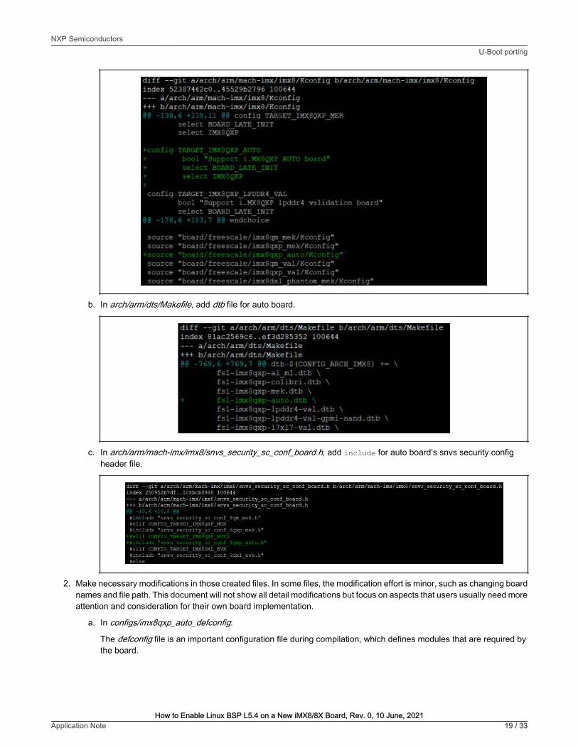
a. In arch/arm/mach-imx/imx8/Kconfig, add TARGET_IMX8QXP_AUTO and auto board’s Kconfig file.
NXP SemiconductorsU-Boot porting
How to Enable Linux BSP L5.4 on a New iMX8/8X Board, Rev. 0, 10 June, 2021Application Note 18 / 33
b. In arch/arm/dts/Makefile, add dtb file for auto board.
c. In arch/arm/mach-imx/imx8/snvs_security_sc_conf_board.h, add include for auto board’s snvs security configheader file.
2. Make necessary modifications in those created files. In some files, the modification effort is minor, such as changing boardnames and file path. This document will not show all detail modifications but focus on aspects that users usually need moreattention and consideration for their own board implementation.
a. In configs/imx8qxp_auto_defconfig:
The defconfig file is an important configuration file during compilation, which defines modules that are required bythe board.
NXP SemiconductorsU-Boot porting
How to Enable Linux BSP L5.4 on a New iMX8/8X Board, Rev. 0, 10 June, 2021Application Note 19 / 33
Taking our auto as example, comparing to MEK board’s defconfig file, make the following changes in autoboard’s defconfig.
By default, the u-boot will reserve 128 MB memory region for M4 program to use, from0x88000000 to 0x90000000. This is defined by CONFIG_BOOTAUX_RESERVED_MEM_BASE andCONFIG_BOOTAUX_RESERVED_MEM_SIZE in defconfig. To change the size of memory region for M4program to use, modify this CONFIG and the memory region assignment in Creating a new board file.
NOTE
For features and drivers to enable on their new board, add related CONFIG to the board’s defconfig file.
b. In board/freescale/imx8qxp_auto/imx8qxp_auto.c:
This file contains board-related initialization functions like board_init(). Users can implement their own boardspecific initialization function here or modify existing initialization function for various modules.
For example, if users have GPIO pins to be set during initialization, add these GPIO pins in board_gpio_init()function. Then users need to use dm_gpio_lookup_name() to find the target GPIO, use dm_gpio_request()to request the GPIO, use dm_gpio_set_dir_flags() to set GPIO pin’s direction and flags, and finally usedm_gpio_set_value() to set the output value of target GPIO.
c. In include/configs/imx8qxp_auto.h:
This header file of board contains many board-related macro definitions. Two most common parts to be modified areDRAM size and ENV settings.
NXP SemiconductorsU-Boot porting
How to Enable Linux BSP L5.4 on a New iMX8/8X Board, Rev. 0, 10 June, 2021Application Note 20 / 33
The PHYS_SDRAM_1 defines lower base address of DRAM, and PHYS_SDRAM_2 defines higher base address.The total DRAM size is PHYS_SDRAM_1_SIZE + PHYS_SDRAM_2_SIZE.
If the DRAM size is less than 2 GB, then PHYS_SDRAM_2_SIZE is 0.
Users need to modify the define value of PHYS_SDRAM_1_SIZE and PHYS_SDRAM_2_SIZE according to the DDRdevice on their board.
As for ENV settings, there are many ENV settings already been defined in the header file. Users can add new ENVsettings in CONFIG_EXTRA_ENV_SETTINGS, and modify existing ENV settings, such as, fdt_file and mmcargsdepending on their own requirement.
The ENV settings can also be changed dynamically in U-Boot console with setenv and saveenv command.
d. In arch/arm/dts/fsl-imx8qxp-auto.dts:
The device tree architecture is first introduced in Linux kernel and implemented in U-Boot. The dts file is adata structure describing the hardware components of the board so that the system can use and managethose components.
Users can add or delete device node according to their board design to modify some device node’s parameters, suchas, clock frequency and control pins.
For SPL, there is also a device tree. To reduce the size of SPL, keep only the nodes with pre-relocation properties('u-boot,dm-pre-reloc', 'u-boot,dm-spl') in their device trees. Users can check arch/arm/dts/fsl-imx8qxp-mek-u-boot.dtsi as an example.
6.3 Compiling U-Boot1. Set building environment
The toolchain used to compile U-Boot is same cross-compile toolchain in Compiling ATF. For how to generate and installthe toolchain, see Chapter 4.5.12 How to build U-Boot and Kernel in standalone environment in i.MX Linux® User's Guide(document IMXLUG).
7 Building flash.bin imageFor i.MX8 chips, the flash.bin image, which is actually the boot image container set, can include SCFW, SECO FW, M4 image,ATF image, U-Boot image, and SPL image. ROM code reads the flash.bin image from the boot device and loads it to differentmemory address according to settings.
To simplify the process of generating flash.bin image, use the imx-mkimage tool to combine the the images above to produce thefinal flash.bin boot image and burn to the boot device.
7.1 Copying images to mkimageAfter following steps in Linux BSP releases, download the imx-mkimage source code in the imx-mkimage folder. The contentincludes folders for all supported iMX8 chips.
To generate the flash.bin image, copy all required images into the target chip’s folder. Taking our imx8qxp auto board as anexample, follow the steps as below.
1. Copy SCFW scfw_tcm.bin generated in Compiling SCFW to the imx-mkimage/iMX8QX/ folder.
2. Copy SECO FW mx8qxc0-ahab-container.img to the imx-mkimage/iMX8QX/ folder. Use the following command todownload the image:
For each BSP release, there is an SECO FW version coupled with the release. For how to get the correct SECOFW version, see i.MX Linux® Release Notes (document IMXLXRN).
NOTE
3. Copy ATF image bl31.bin generated in Compiling ATF to the imx-mkimage/iMX8QX/ folder.
4. Copy U-Boot image u-boot.bin and SPL image u-boot-spl.bin generated in Compiling U-Boot to the imx-mkimage/iMX8QX/ folder.
5. Copy M4 image to the imx-mkimage/iMX8QX/ folder, if there is M4 program, and name it as m4_image.bin. For how tocompile M4 images, see MCUXpresso SDK Builder.
7.2 Checking makefileThe makefile for flash.bin image is in imx-mkimage/iMX8QX/soc.mak. By default, many targets have been defined for commonuse case. User can either use these targets to build their flash.bin image directly if the target meets their requirement or modifythe options in these targets or even create a new target for their specific need. The below are some examples.
• flash:
The flash target includes SCFW, SECO FW, ATF and U-Boot image. The u-boot-atf.bin is generated by ATF image bl31.bincombined with u-boot.bin image.
NXP SemiconductorsBuilding flash.bin image
How to Enable Linux BSP L5.4 on a New iMX8/8X Board, Rev. 0, 10 June, 2021Application Note 22 / 33
Since the flash target doesn’t include SPL image, the A core booting address is 0x80000000, as shown above.
• flash_regression_linux_m4:
The flash_regression_linux_m4 target adds M4 image comparing to the flash target. The following two parts need to benoticed for this target.
— The -flags 0x00200000 option
This is the boot flags that will be passed to SCFW during boot. The definition of the flags can be found in sc_fw_port.pdf.
Table 3. Flag definition
Flag Bit Meaning
SC_BD_FLAGS_NOT_SECURE 16 Initial boot partition is not secure
SC_BD_FLAGS_NOT_ISOLATED 17 Initial boot partition is not isolated
SC_BD_FLAGS_RESTRICTED 18 Initial boot partition is restricted
SC_BD_FLAGS_GRANT 19 Initial boot partition grants access to the SCFW
SC_BD_FLAGS_NOT_COHERENT 20 Initial boot partition is not coherent
SC_BD_FLAGS_ALT_CONFIG 21 Alternate SCFW config (passed to board.c)
SC_BD_FLAGS_EARLY_CPU_START 22 Start some CPUs early
SC_BD_FLAGS_DDRTEST 23 Config for DDR stress test
SC_BD_FLAGS_NO_AP 24 Don't boot AP even if requested by ROM
As shown in Table 3, -flags 0x00200000 means SC_BD_FLAGS_ALT_CONFIG is set. This flag is used in theboard_system_config() function in board.c. SCU creates partition and assigns resources for M4 only when this flag is set.
— The booting address of M4 core
Based on user’s requirement, M4 core can boot from internal memory TCM, external memory DRAM or external devicelike NOR Flash. When compiling the M4 image with M4 SDK, there are specific link files for each method. Users needto choose the correct link files according to the boot method they have chosen and align the booting address here withthe address defined in the link files.
◦ For the flash_regession_linux_m4 target, assume that the boot method is booting from TCM. Therefore, thebooting address is 0x34FE0000.
NXP SemiconductorsBuilding flash.bin image
How to Enable Linux BSP L5.4 on a New iMX8/8X Board, Rev. 0, 10 June, 2021Application Note 23 / 33
◦ For targets ending with m4_ddr, assume that the boot method is booting from DDR and the booting address is0x88000000.
◦ For targets ending with m4_xip, assume the boot method is booting from QSPI NOR Flash and the bootingaddress is 0x08081000, as shown below.
• flash_linux_m4:
The difference between flash_linux_m4 and flash_regession_linux_m4 is that SPL image is added. For SPL boot, the ROMcode only loads SPL image to OCRAM and after SPL image boots from OCRAM, it will try to read remain image (i.e.u-boot-aft-container.img) from boot device and load to DDR. The following three parts need to be noticed for this target.
— The u-boot-aft-container.img image
This image is generated from ATF image bl31.bin and U-Boot image u-boot-hash.bin as below. It will also include TEEimage tee.bin if it exists in the folder.
— The -dcd skip option
NXP SemiconductorsBuilding flash.bin image
How to Enable Linux BSP L5.4 on a New iMX8/8X Board, Rev. 0, 10 June, 2021Application Note 24 / 33
In non-SPL boot method, the ROM code loads A core booting image from boot device to DRAM, so the ROM code needto initialize DDR before loading. But in SPL boot method, the ROM code only need to load SPL image into OCRAM, thusthe DDR initialization can be skipped in ROM code and be done later in SCFW. The -dcd skip option sets a flag in imagecontainer, so when ROM code read the image container, it will know how it configures.
If the M4 needs to boot from DDR, ROM code still needs to load M4 image into DRAM. In such cases, the -dcd skipis not applicable, as shown below in the flash_linux_m4_ddr target.
NOTE
For more details about -dcd skip option and DDR initialization flow, see Chapter 4.6 DDR Configurationin sc_fw_port.pdf.
— The booting address of A core
In SPL boot method, since the ROM code will load SPL image into OCRAM, the booting address of A core also changesto OCRAM address 0x00100000.
• flash_linux_m4_xip:
The main change between the flash_linux_m4_xip and flash_linux_m4 is that M4 is booting from QSPI NOR Flash deviceinstead of TCM. Besides the M4 core booting address mentioned above, the QSPI header file also needs to be noticed.
For flash.bin image to boot from QSPI/FSPI device, the header file is needed in the image for ROM code to configureQSPI/FSPI device. The sample QSPI/FSPI header file is provided in imx-mkimage/scripts/fspi_header. To choose QSPI/FSPIdevice as boot device, modify the header file to fit the devices.
For example, in the sample header file, we can see that the value for offset 0x44-0x47 is 0x01010200.
To translate this setting, see Chapter 5.8.3.3 FlexSPI configuration parameters in i.MX8QXP Reference Manual.
NXP SemiconductorsBuilding flash.bin image
How to Enable Linux BSP L5.4 on a New iMX8/8X Board, Rev. 0, 10 June, 2021Application Note 25 / 33
devicetype 0x044 1 1 - Serial NOR
sflashPadType 0x045 j 1 - Single pad
2 - Dual pads
4 - Quad pads
8 - Octal pads
serialClkFreq 0x046 1 Chip specific value, for this silicon
1 - 20 MHz
2 - 50 MHz
3 - 62 MHz for SDR and 200 MHz for DDR
4 - 80 MHz
5 - 100 MHz
6 - 133 MHz
7 - 166 MHz for SDR and 200 MHz for DDR
Other values: 20 MHz
IutCustomSeqEnable 0x047 1 0- Use predefined LUT sequence index and number
1 - Use LUT sequence parameters provided in this block
Here we can see that, in the sample header file,
— The value of deviceType is 0x01, which is Serial NOR.
— The vlaue of sflashPadType is 0x1, which is Single pad.
— The value of serialClkFreq is 0x02, which is 50 MHz.
— The value of lutCustomSeqEnable is 0x00, which is Use pre-defined LUT sequence index and number.
For all parameters in the header file, check the definition in Chapter 5.8.3.3 FlexSPI configuration parameters in i.MX8QXPReference Manual and set the correct value for the FSPI device.
7.3 Generating flash.bin imageTo generate flash.bin image, compile an internal tool, mkimage_imx8, using the gcc in user’s Linux host environment. The sourcecode of mkimage_imx8 is in imx-mkimage/src.
Since it will be automatically compiled when using the following command to generate flash.bin image, users don’t need to compilemkimage_imx8 separately.
The command to generate flash.bin image is:
$make SOC=<SOC_TARGET> REV=<SOC_REV> [TARGET]
The SOC_TARGET is the target chips, SOC_REV is the reversion of chips, and TARGET is introduced in Checking makefile.
NXP SemiconductorsBuilding flash.bin image
How to Enable Linux BSP L5.4 on a New iMX8/8X Board, Rev. 0, 10 June, 2021Application Note 26 / 33
Since for iMX8QXP B0 and C0 chips, the SECO FW is not compatible with each other, the REV is used to specifythe version of SECO FW.
• For iMX8QXP B0 chips, use the SECO FW, mx8qxb0-ahab-container.img.
• For iMX8QXP C0 chips, use the SECO FW, mx8qxc0-ahab-container.img.
NOTE
Take our imx8qxp auto board as an example, to build a flash.bin image with M4 image and SPL image, use the command:
$make SOC=iMX8QX REV=C0 flash_linux_m4
The flash.bin binary file is generated in imx-mkimage/iMX8QX/flash.bin.
7.4 Burning flash.bin imagesFor iMX8/8X chips, the ROM code supports to boot from following boot devices:
• SD/MMC
• NAND flash
• FlexSPI NOR flash
• Serial downloader support on USB 2.0 OTG and USB 3.0 (as 2.0)
Usually SD card is the most efficient way to verify if the generated flash.bin image can boot the board successfully.
To burn flash.bin image into SD card, insert the SD card on a Linux host PC. Assuming the SD card is recognized as /dev/sdx,use the following command to burn flash.bin into SD card:
For how to burn flash.bin image into other boot device, see Chapter 4.4 Downloading images in i.MX Linux® User's Guide(document IMXLUG).
8 Linux kernel portingComparing to previous chapters, users are more familiar to Linux kernel porting. This chapter focuses on the porting effort for ourimx8qxp auto reference board to illustrate the process of adding new device tree file and drivers for a new customized board.
For Linux file system porting such as adding new user space tools or package, see i.MX_Yocto_Project_User’s_Guide.pdf.
8.1 Creating files for a new boardTo create files for a new board, perform the following steps:
1. Add new board defconfig in arch/arm64/configs/.
The defconfig file defines the component that will be included in the Linux kernel. In general, each board has a specificdefconfig file according to the hardware design and software requirement.
The imx8qxp auto board, it’s quite similar to the MEK reference board. Therefore, use the default defconfig file in arch/arm64/configs/imx_v8_defconfig directly as the defconfig file. For other iMX8 customized boards, use the imx_v8_defconfigas reference and add modification accordingly.
2. Add a new board dts in arch/arm64/boot/dts/freescale/.
For the imx8qxp auto board, create the following dts/dtsi files, which are copied from files for MEK board to save the efforts.
NXP SemiconductorsLinux kernel porting
How to Enable Linux BSP L5.4 on a New iMX8/8X Board, Rev. 0, 10 June, 2021Application Note 27 / 33
Table 4. Device tree files created for auto board in Linux kernel
File location Description
arch/arm64/boot/dts/freescale/imx8qxp-auto.dts The dts files for auto board without rpmsg, which includesimx8qxp.dtsi and imx8x-auto.dtsi
arch/arm64/boot/dts/freescale/imx8qxp-auto-rpmsg.dts The dts file for auto board with rpmsg, which includesimx8qxp-auto.dts and imx8x-auto-rpmsg.dtsi
arch/arm64/boot/dts/freescale/imx8x-auto.dtsi The dtsi file for auto board without rpmsg, which enables thedevice node that needed
arch/arm64/boot/dts/freescale/imx8x-auto-rpmsg.dtsi The dtsi file for auto board with rpmsg, which enables thedevice node that needed
arch/arm64/boot/dts/freescale/imx8qxp-auto-enet-tja1101.dts The dts file for auto board with TJA1101 Ethernet PHYenabled, which includes imx8qxp-auto.dts and imx8qxp-auto-enet-tja1101.dtsi
arch/arm64/boot/dts/freescale/imx8qxp-auto-enet-tja1101.dtsi The dtsi file for auto board with TJA1101 EthernetPHY enabled
The difference between dts with and without rpmsg is on resources related to M4 core. If M4 core is used, assign some ofthe peripheral interface resources to M4 partition in SCFW as mentioned before, like I2C and Flexcan. Therefore, disablethese resources in dts or use virtual driver like imx_rpmsg_i2c for I2C interface.
3. Add new drivers for devices on the board.
For an imx8qxp auto board, add the following three hardware components in the board design:
• MIPI-CSI with NVP6324 automotive AHD solution
• LVDS display with TI DS90UB947/948 Serdes (through FPD-Link III) for automotive application
• MIPI-DSI display with Maxim 96752/96755 Serdes (through GMSL2) for automotive application
Table 5 lists the corresponding drivers to be added in the kernel code.
Table 5. Driver files added for auto board in Linux kernel
File location Description
drivers/gpu/drm/bridge/ds90ub94x.c Driver of TI DS90UB947/948 Serdes
drivers/gpu/drm/bridge/mx9675x.c Driver of Maxim 96752/96755 Serdes
drivers/media/platform/imx8/nvp6324/ New folder for NVP6324
drivers/media/platform/imx8/nvp6324/Kconfig Kconfig of NVP6324 driver
drivers/media/platform/imx8/nvp6324/Makefile Makefile of NVP6324 driver
drivers/media/platform/imx8/nvp6324/nvp6324.h Header file of NVP6324 driver
drivers/media/platform/imx8/nvp6324/nvp6324_core.c Core function file of NVP6324 driver
drivers/media/platform/imx8/nvp6324/nvp6324_mipi.c MIPI settings of NVP6324 driver
Table continues on the next page...
NXP SemiconductorsLinux kernel porting
How to Enable Linux BSP L5.4 on a New iMX8/8X Board, Rev. 0, 10 June, 2021Application Note 28 / 33
Table 5. Driver files added for auto board in Linux kernel (continued)
File location Description
drivers/media/platform/imx8/nvp6324/nvp6324_video.c Video mode settings of NVP6324 driver
drivers/media/platform/imx8/nvp6324/nvp6324_video_eq.c Video event queue settings of NVP6324 driver
8.2 Modifying files for new boardTo modify files for a new board, perform the following steps:
1. Edit related makefiles to be compiled into kernel image. In the imx8qxp auto board example, the related makefiles include:
• arch/arm64/boot/dts/freescale/Makefile
Add imx8qxp auto board’s dtb files.
• drivers/gpu/drm/bridge/Makefile
Add ds90ub94x and mx9675x driver.
• drivers/media/platform/imx8/Makefile
Include nvp6324 folder for nvp6324 driver.
NXP SemiconductorsLinux kernel porting
How to Enable Linux BSP L5.4 on a New iMX8/8X Board, Rev. 0, 10 June, 2021Application Note 29 / 33
2. Modify the dts files according to the board design. For example, on imx8qxp auto board, the connection on LVDS0 isdesigned in such method:
Therefore, the ldb1 and i2c0_mipi_lvds0 device node in imx8x-auto.dtsi is changed accordingly as below.
NXP SemiconductorsLinux kernel porting
How to Enable Linux BSP L5.4 on a New iMX8/8X Board, Rev. 0, 10 June, 2021Application Note 30 / 33
The connection order is represented by the endpoint matching in the dts.
For other board design changes, the related modification is also added in the dts in a similar method.
3. Modify some existing drivers to add specific features or implementations for the new board.
For example, in the imx8qxp auto board design, to connect a MIPI DSI panel on Maxim 96755 Serdes, add this panel’ssetting in drivers/gpu/drm/panel/panel-simple.c as below.
NXP SemiconductorsLinux kernel porting
How to Enable Linux BSP L5.4 on a New iMX8/8X Board, Rev. 0, 10 June, 2021Application Note 31 / 33
8.3 Compiling Linux KernelTo compile Linux Kernel, perform the following steps:
1. Set building environment.
The toolchain used to compile Linux Kernel is the same cross-compile toolchain used for compiling ATF and U-Boot. Forhow to generate and install the toolchain, see Chapter 4.5.12 How to build U-Boot and Kernel in standalone environmentin i.MX Linux® User's Guide (document IMXLUG).
To build the Linux Kernel for the target board, perform as below:
a. Use the following command to generate configuration file for the board. In this example, the default defconfig is usedfor the auto board.
$ make imx_v8_defconfig
b. Use the following command to generate Linux Kernel for the target board. The related dtb files are also generated.
$ make -j8
c. The compiled Linux Kernel image is arch/arm64/boot/Image and dtb files are located in arch/arm64/boot/dts/freescale/ folder.
8.4 Burning Linux Kernel• If the SD/MMC is already partitioned into boot partition and rootfs partition, use the following command to copy kernel image
• If the SD/MMC is not partitioned yet, follow the step in Chapter 4.3 Preparing an SD/MMC card to boot of i.MX Linux® User'sGuide (document IMXLUG) to partition SD/MMC and then burn kernel image and dtb to boot partition.
9 Revision history
Revision number Date Substantive changes
0 10 June, 2021 Initial release
NXP SemiconductorsRevision history
How to Enable Linux BSP L5.4 on a New iMX8/8X Board, Rev. 0, 10 June, 2021Application Note 32 / 33
Information in this document is provided solely to enable system and software implementers to use NXP products. Thereare no express or implied copyright licenses granted hereunder to design or fabricate any integrated circuits based on theinformation in this document. NXP reserves the right to make changes without further notice to any products herein.
NXP makes no warranty, representation, or guarantee regarding the suitability of its products for any particular purpose, nordoes NXP assume any liability arising out of the application or use of any product or circuit, and specifically disclaims anyand all liability, including without limitation consequential or incidental damages. “Typical” parameters that may be providedin NXP data sheets and/or specifications can and do vary in different applications, and actual performance may vary overtime. All operating parameters, including “typicals,” must be validated for each customer application by customer's technicalexperts. NXP does not convey any license under its patent rights nor the rights of others. NXP sells products pursuant tostandard terms and conditions of sale, which can be found at the following address: nxp.com/SalesTermsandConditions.
Right to make changes - NXP Semiconductors reserves the right to make changes to information published in thisdocument, including without limitation specifications and product descriptions, at any time and without notice. Thisdocument supersedes and replaces all information supplied prior to the publication hereof.
Security — Customer understands that all NXP products may be subject to unidentified or documented vulnerabilities.Customer is responsible for the design and operation of its applications and products throughout their lifecycles to reducethe effect of these vulnerabilities on customer’s applications and products. Customer’s responsibility also extends to otheropen and/or proprietary technologies supported by NXP products for use in customer’s applications. NXP accepts noliability for any vulnerability. Customer should regularly check security updates from NXP and follow up appropriately.Customer shall select products with security features that best meet rules, regulations, and standards of the intendedapplication and make the ultimate design decisions regarding its products and is solely responsible for compliance with alllegal, regulatory, and security related requirements concerning its products, regardless of any information or support thatmay be provided by NXP. NXP has a Product Security Incident Response Team (PSIRT) (reachable at [email protected])that manages the investigation, reporting, and solution release to security vulnerabilities of NXP products.
NXP, the NXP logo, NXP SECURE CONNECTIONS FOR A SMARTER WORLD, COOLFLUX,EMBRACE, GREENCHIP,HITAG, ICODE, JCOP, LIFE, VIBES, MIFARE, MIFARE CLASSIC, MIFARE DESFire, MIFARE PLUS, MIFARE FLEX,MANTIS, MIFARE ULTRALIGHT, MIFARE4MOBILE, MIGLO, NTAG, ROADLINK, SMARTLX, SMARTMX, STARPLUG,TOPFET, TRENCHMOS, UCODE, Freescale, the Freescale logo, AltiVec, CodeWarrior, ColdFire, ColdFire+, the EnergyEfficient Solutions logo, Kinetis, Layerscape, MagniV, mobileGT, PEG, PowerQUICC, Processor Expert, QorIQ, QorIQQonverge, SafeAssure, the SafeAssure logo, StarCore, Symphony, VortiQa, Vybrid, Airfast, BeeKit, BeeStack, CoreNet,Flexis, MXC, Platform in a Package, QUICC Engine, Tower, TurboLink, EdgeScale, EdgeLock, eIQ, and Immersive3D aretrademarks of NXP B.V. All other product or service names are the property of their respective owners. AMBA, Arm, Arm7,Arm7TDMI, Arm9, Arm11, Artisan, big.LITTLE, Cordio, CoreLink, CoreSight, Cortex, DesignStart, DynamIQ, Jazelle,Keil, Mali, Mbed, Mbed Enabled, NEON, POP, RealView, SecurCore, Socrates, Thumb, TrustZone, ULINK, ULINK2,ULINK-ME, ULINK-PLUS, ULINKpro, μVision, Versatile are trademarks or registered trademarks of Arm Limited (or itssubsidiaries) in the US and/or elsewhere. The related technology may be protected by any or all of patents, copyrights,designs and trade secrets. All rights reserved. Oracle and Java are registered trademarks of Oracle and/or its affiliates. ThePower Architecture and Power.org word marks and the Power and Power.org logos and related marks are trademarks andservice marks licensed by Power.org.