Installation Job Aid (English) for AvayaVirtual Services Platform 7000 Series
Release 10.3.1NN47202-305
Issue 02.02May 2014
How to get helpTo access the complete range of services and support that Avaya provides, go to www.avaya.com.
You can also go to www.avaya.com/support to access the following pages:
• technical documentation
• product training
• technical support
If you purchased a service contract for your Avaya product from a distributor or authorized resellerand you need assistance, contact the technical support staff for that distributor or reseller.
Notices and alertsNotice paragraphs alert you about issues that require your attention.
Following are descriptions of the types of notices used in this document.
Note:Notes provide tips and useful information regarding the installation and operation of Avayaproducts.
Electrostatic alert:ESD notices provide information about how to avoid discharge of static electricity andsubsequent damage to Avaya products.
Caution:Caution notices provide information about how to avoid possible service disruption or damage toAvaya products.
Warning:Warning notices provide information about how to avoid personal injury when working withAvaya products.
Voltage:Danger—High Voltage notices provide information about how to avoid a situation or conditionthat can cause serious personal injury or death from high voltage or electric shock.
Danger:Danger notices provide information about how to avoid a situation or condition that can causeserious personal injury or death.
Safety messagesSafety messages are an important part of the technical documentation. The messages alert you tohazards to personnel and equipment and provide guidance for the safe operation of your equipment.Failure to comply with the safety messages could result in equipment damage and personal injury.
Following are the most common types of safety messages.
Warning:Installation must be performed by qualified personnel only. Read and follow all warning noticesand instructions marked on the product or included in the documentation.
Voltage:This equipment relies on the building's installation for overcurrent protection. Ensure that a fuseor circuit breaker no larger than 120 VAC, 15 A U.S. (240 VAC, 16 A International) is used onthe phase conductors.
Caution:This device is a Class A product. In a domestic environment, this device can cause radiointerference, in which case the user may be required to take appropriate measures.
Caution:When mounting this device in a rack, do not stack units directly on top of one another in therack. Each unit must be secured to the rack with appropriate mounting brackets. Mountingbrackets are not designed to support multiple units.
Voltage:Use only power cords that have a grounding path. Without a proper ground, a person whotouches the switch is in danger of receiving an electrical shock. Lack of a grounding path to theswitch can result in excessive emissions.
Warning:Disconnecting the power cord is the only way to turn off power to this device. Always connectthe power cord in a location that can be reached quickly and safely in case of an emergency.
May 2014 Installation Job Aid (English) for Avaya Virtual Services Platform 7000 Series 2
Warning:Fiber optic equipment can emit laser or infrared light that can injure your eyes. Never look intoan optical fiber or connector port. Always assume that fiber optic cables are connected to a lightsource.
Installation preparationBefore you begin
Ensure the area where you install and use the switch meets environmental requirements.
You can install a single switch on any flat surface that can safely support the weight of the switchand attached cables. A switch with two power supplies and MDA weighs 24.98 lbs (11.33 kg). Cableweight varies for each installation.
You can also install the switch in an equipment rack using the brackets provided or you can use theoptional four post extended bracket kit (sold separately).
Environmental requirementsThe following list describes the requirements for the switch environment.
• ambient temperature between 32°F and 106°F (0°C and 50°C)• relative humidity between 10% and 90% noncondensing• no nearby heat sources such as hot air vents or direct sunlight• no nearby sources of severe electromagnetic noise• no excessive dust• adequate power source within six feet; one circuit required for each power supply• at least 2 inches (5.08 cm) on all sides of the switch unit for ventilation• adequate space at the front and rear of the switch for access to cables
Installing the fan trays and power supplyYour switch supports a combination of field-replaceable power supplies and cooling fan trays. Twofan trays are included with your switch. You must install the two fan trays and at least one powersupply before using the switch. The switch supports an optional second power supply forredundancy and load sharing.
To install the fan trays and power supplies to your switch, use the following procedure.
May 2014 Installation Job Aid (English) for Avaya Virtual Services Platform 7000 Series 3
Important:
Supported cooling airflow directions are: front to back or back to front. The airflow direction offan trays and power supplies are labelled and fixed. The fan trays and power supplies do notsupport the ability to change their airflow direction. Avaya recommends that you install the firstpower supply in PSU1 to determine the airflow direction.
Before you beginVerify that the fan trays and power supply are compatible—ensure that the airflow direction for allfans and power supplies match.
Procedure1. Insert each fan-tray into a rear fan-tray slot.
2. Verify that each fan-tray is fully seated in the slot and secure each fan-tray with two thumbscrews.
3. Insert each power supply into a rear power supply slot.
If a blanking plate covers the required power-supply slot, remove the plate before insertingthe power-supply.
4. Verify that each power-supply is fully seated in the slot and securely clipped in place.
ExampleThe following figure shows how to properly insert the cooling fan trays and power supplies into yourswitch.
Figure 1: Installing the fan trays and power suppliesNext stepsAfter you install the two fan trays and at least one power supply, you can install and connect powerto the switch.
AC power connectionsTo connect your switch to AC power, you require an AC power cord that meets the requirements ofyour local electrical code.
May 2014 Installation Job Aid (English) for Avaya Virtual Services Platform 7000 Series 4
International power-cord specificationsRefer to the following table for power-cord plug specifications.
Voltage:Risk of injury from electric shock
Before working on this equipment, be aware of proper safety practices and hazards involved withelectrical circuits. Use only power cords that have a grounding path. Ensure the switch is properlygrounded before connecting a power source.
Note:VSP 7000 Series switches do not have a power switch. When you connect the AC power cordto a suitable AC power outlet, the switch powers up immediately. Ensure that you connect theAC power cord to the back of the switch, and then connect the cord to a power outlet. You mustuse the correct power cord for the switch and power supply.
Country and plug description Specifications Typical plugContinental Europe
• CEE7 standard VII male plug
• Harmonized cord (HAR markingon the outside of the cord jacketto comply with the CENELECHarmonized Document HD-21)
220 or 230 VAC
50 Hz
Single phase
Wire diameter 0.75 mm2
U.S./Canada/Japan
• NEMA5–15P male plug
• UL-recognized (UL stamped oncord jacket)
• CSA-certified (CSA labelsecured to the cord)
100 or 120 VAC
50/60 Hz
Single phase
United Kingdom
• BS1363 male plug with fuse
• Harmonized cord
240 VAC
50 Hz
Single Phase
May 2014 Installation Job Aid (English) for Avaya Virtual Services Platform 7000 Series 5
Country and plug description Specifications Typical plugAustralia
AS3112–1981 male plug
240 VAC
50 Hz
Single phase
Figure 2: Connecting AC power cord to the switch
Note:Secondary power supply is optional for redundancy and load sharing.
DC power connectionsTo connect your switch to DC power you require DC power cables and ground cables that meet therequirements of your local electrical code. Avaya does not supply the cables for connecting the DCpower supply to the DC power source. Select cables that comply with the electrical code of thecountry where you use the DC power supply.
DC power supply connections
Caution:Risk of equipment damage
May 2014 Installation Job Aid (English) for Avaya Virtual Services Platform 7000 Series 6
Make sure that the connection cables used with the DC power supply are appropriate for usewith your DC power source. Consider gauge, flammability, and mechanical serviceability whendetermining the type of cables to use.
Voltage:Risk of injury from electric shockBefore working on this equipment, be aware of proper safety practices and hazards involved withelectrical circuits. Use only power cords that have a grounding path. Ensure the switch is properlygrounded before connecting a power source.
Note:VSP 7000 Series switches do not have a power switch. Ensure that your DC power source is offwhen connecting DC power cables to the back of the switch power supply. Verify all terminalconnections, and then connect the DC power cables to your DC power source. When youconnect the DC power supply to a suitable DC power source, the switch powers up immediately.
You must prepare the cables by stripping insulation from the end of the cable approximately 0.8 inch(2 cm) before you fasten each cable to a power supply terminal. The following figure shows the DCpower supply terminals and DC power supply status LEDs.
May 2014 Installation Job Aid (English) for Avaya Virtual Services Platform 7000 Series 7
Figure 3: DC power supply terminals
Installing the switch in an equipment rackBefore you begin
Tool requirements
• a Phillips screwdriver to attach brackets to the switch and the switch to the rack.• a Hex wrench to attach the optional four-post rack mount brackets (sold separately).
May 2014 Installation Job Aid (English) for Avaya Virtual Services Platform 7000 Series 8
Rack requirements
• space of 2.8 inches (7.1 cm) for each switch in an E1A or 1EC standard 19 inch (48.2 cm)equipment rack and T1A 23 inch (58.5 cm) equipment rack.
• appropriate rack space to accommodate 1U switch height (44 mm).• rack bolted to floor and braced if necessary• rack must be grounded to the same grounding electrode used by the power service in the area.
The ground path must be permanent and must not exceed 1 Ohm of resistance from the rackto the grounding electrode.
About this taskPerform the following procedure to install your switch in an equipment rack.
Procedure1. Ensure power is disconnected from the switch.
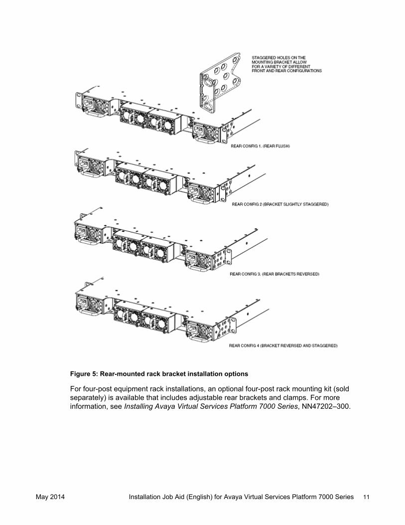
2. Attach a bracket to each side of the switch with the included screws.
The included mounting bracket allows for many different options for front and rear mountingpositions, see the following figures. Attach the brackets in the best position for your specificequipment rack.
May 2014 Installation Job Aid (English) for Avaya Virtual Services Platform 7000 Series 9
For four-post equipment rack installations, an optional four-post rack mounting kit (soldseparately) is available that includes adjustable rear brackets and clamps. For moreinformation, see Installing Avaya Virtual Services Platform 7000 Series, NN47202–300.
May 2014 Installation Job Aid (English) for Avaya Virtual Services Platform 7000 Series 11
Figure 6: Optional four-post rack mount brackets
3. Slide the switch into the rack.
4. Fasten the switch to the equipment rack with rack mount screws.
For four-post equipment rack installations, fasten the switch to the equipment rack with rackmount screws on all four corners, then secure and tighten the rear bracket with the includedclamps.
5. Verify that the switch is securely fastened to the rack.
You can proceed with the installation by connecting power and network connections to theswitch.
Power specificationsThe VSP 7000 Series switches support the following power supply configurations:
• One AC power supply
• One DC power supply
• Two AC power supplies
• Two DC power supplies
• One AC power supply and one DC power supply
May 2014 Installation Job Aid (English) for Avaya Virtual Services Platform 7000 Series 12
When you operate the switch with two power supplies, the switch supports redundancy, loadsharing, and full hot-swap replacement of a power supply for uninterruptible operation. The powersupply is location independent; you can install an AC or DC power supply into either power supplyslot on the switch.
For cooling, the switch supports two airflow patterns: front to back or back to front. The air flowdirection is determined by the main power supply. All power supplies and fan trays must match theairflow direction. A switch can operate for a brief period with one fan tray, but one fan may not beable to achieve maximum environmental conditions.
Each switch is shipped with two fan trays and can support up to two power supplies.
Important:
Power supply and fan tray direction must match. If you require front to back cooling, you mustensure that the power supply is designated for front to back cooling. Or, if you require back tofront cooling, you must ensure that the power supply is designated for back to front cooling.
The following table describes the AC and DC power specifications for the VSP 7000 switch.
Parameter Input voltage Maximum power ratingAC Input 100–240 VAC, 3.7A Max, 50/60
Hz300 W
DC Input 48 VDC, 8.0A Max 300 W
May 2014 Installation Job Aid (English) for Avaya Virtual Services Platform 7000 Series 13