How-to Guide: Supporting Documentation In Compliance with 2016 New York City Energy Conservation Code GENERAL BUILDING ENVELOPE MECHANICAL SYSTEMS LIGHTING & ELECTRICAL POWER OTHER REQUIREMENTS NOTE: In this How-To Guide: Supporting Documentation, selected Energy Code provisions have been generalized, summarized, rephrased, and/or highlighted. This guide is intended: 1) To provide general guidance for the job applications seeking compliance with the 2016 NYCECC; 2) Not to replace or represent the entire 2016 NYCECC and related regulations of the City of New York and the Department of Buildings; and 3) Not to provide complete compliance solutions for any particular type of job or work. Comprehensive mandates, applicability, exemptions, exceptions and options will be found in the 2016 NYCECC and related regulations of the City of New York and the Department of Buildings.
Transcript
How-to Guide: Supporting Documentation
In Compliance with
2016 New York City Energy Conservation Code
GENERAL
BUILDING ENVELOPE
MECHANICAL SYSTEMS
LIGHTING & ELECTRICAL POWER
OTHER REQUIREMENTS
NOTE: In this How-To Guide: Supporting Documentation, selected Energy Code provisions have been generalized, summarized, rephrased, and/or highlighted. This guide is intended: 1) To
provide general guidance for the job applications seeking compliance with the 2016 NYCECC; 2) Not to replace or represent the entire 2016 NYCECC and related regulations of the City of
New York and the Department of Buildings; and 3) Not to provide complete compliance solutions for any particular type of job or work. Comprehensive mandates, applicability, exemptions,
exceptions and options will be found in the 2016 NYCECC and related regulations of the City of New York and the Department of Buildings.
GENERAL BUILDING ENVELOPE [BE - 1] MECHANICAL SYSTEMS LIGHTING & ELECTRICAL POWER OTHER REQUIREMENTS
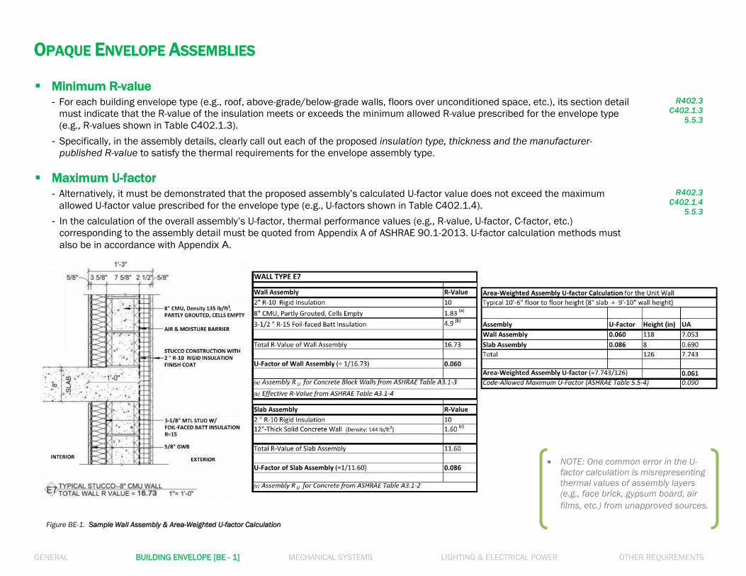
NOTE: One common error in the U-
factor calculation is misrepresenting
thermal values of assembly layers
(e.g., face brick, gypsum board, air
films, etc.) from unapproved sources.
OPAQUE ENVELOPE ASSEMBLIES Minimum R-value
- For each building envelope type (e.g., roof, above-grade/below-grade walls, floors over unconditioned space, etc.), its section detail
must indicate that the R-value of the insulation meets or exceeds the minimum allowed R-value prescribed for the envelope type
(e.g., R-values shown in Table C402.1.3).
- Specifically, in the assembly details, clearly call out each of the proposed insulation type, thickness and the manufacturer-
published R-value to satisfy the thermal requirements for the envelope assembly type.
R402.3
C402.1.3
5.5.3
Maximum U-factor
- Alternatively, it must be demonstrated that the proposed assembly’s calculated U-factor value does not exceed the maximum
allowed U-factor value prescribed for the envelope type (e.g., U-factors shown in Table C402.1.4).
- In the calculation of the overall assembly’s U-factor, thermal performance values (e.g., R-value, U-factor, C-factor, etc.)
corresponding to the assembly detail must be quoted from Appendix A of ASHRAE 90.1-2013. U-factor calculation methods must
GENERAL BUILDING ENVELOPE [BE - 2] MECHANICAL SYSTEMS LIGHTING & ELECTRICAL POWER OTHER REQUIREMENTS
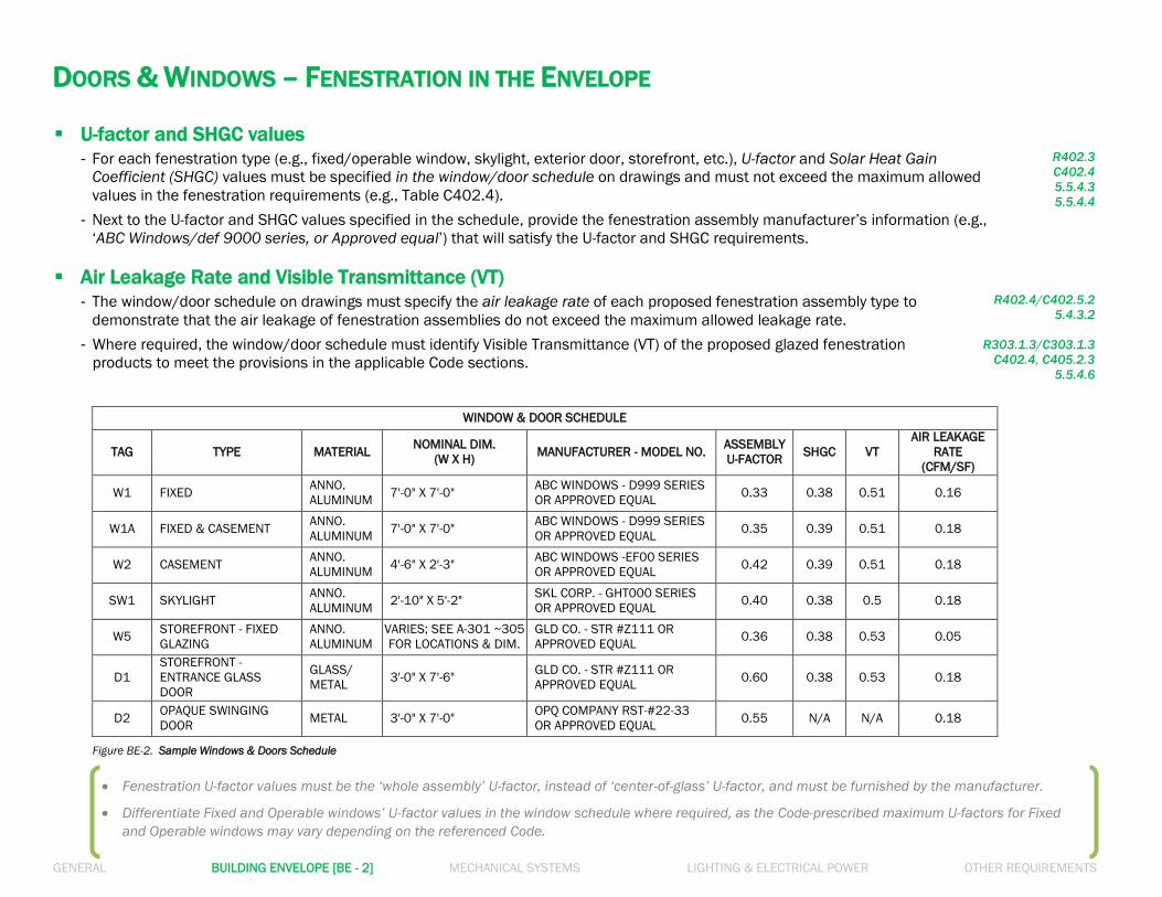
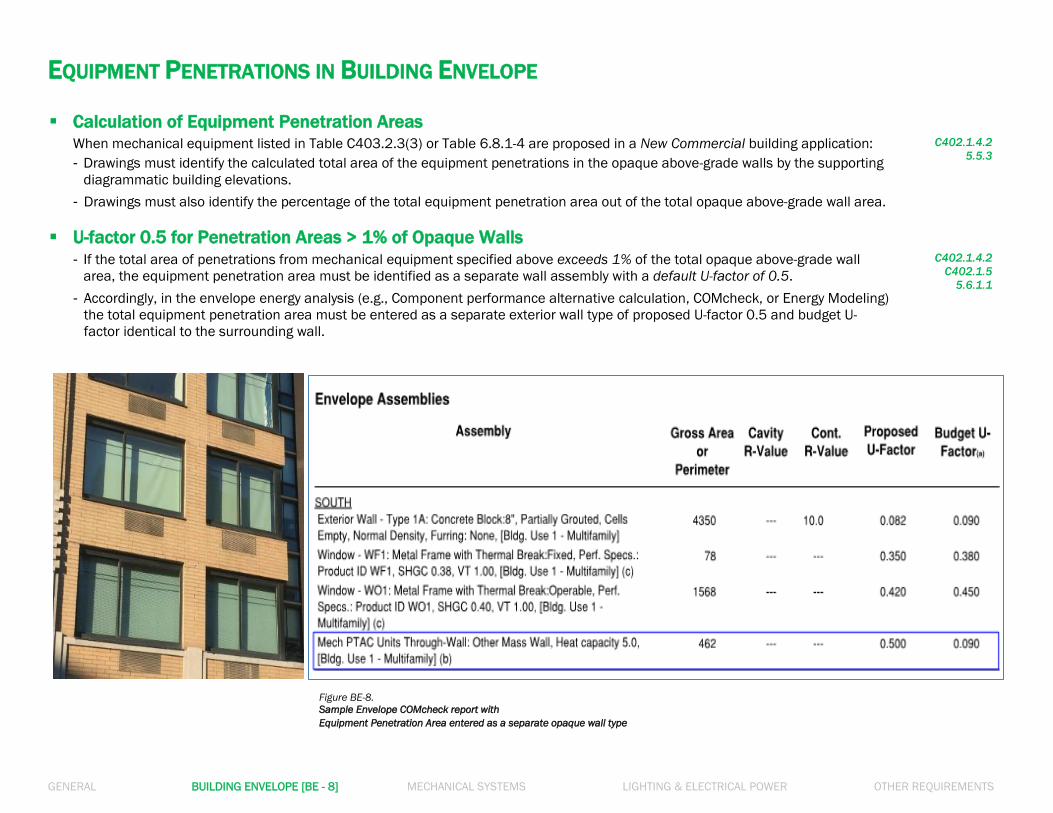
Figure BE-2. Sample Windows & Doors Schedule
DOORS & WINDOWS – FENESTRATION IN THE ENVELOPE U-factor and SHGC values
- For each fenestration type (e.g., fixed/operable window, skylight, exterior door, storefront, etc.), U-factor and Solar Heat Gain
Coefficient (SHGC) values must be specified in the window/door schedule on drawings and must not exceed the maximum allowed
values in the fenestration requirements (e.g., Table C402.4).
- Next to the U-factor and SHGC values specified in the schedule, provide the fenestration assembly manufacturer’s information (e.g.,
‘ABC Windows/def 9000 series, or Approved equal’) that will satisfy the U-factor and SHGC requirements.
R402.3
C402.4
5.5.4.3
5.5.4.4
Air Leakage Rate and Visible Transmittance (VT)
- The window/door schedule on drawings must specify the air leakage rate of each proposed fenestration assembly type to
demonstrate that the air leakage of fenestration assemblies do not exceed the maximum allowed leakage rate.
- Where required, the window/door schedule must identify Visible Transmittance (VT) of the proposed glazed fenestration
products to meet the provisions in the applicable Code sections.
R402.4/C402.5.2
5.4.3.2
R303.1.3/C303.1.3
C402.4, C405.2.3
5.5.4.6
WINDOW & DOOR SCHEDULE
TAG TYPE MATERIAL NOMINAL DIM.
(W X H) MANUFACTURER - MODEL NO.
ASSEMBLY
U-FACTOR SHGC VT
AIR LEAKAGE
RATE
(CFM/SF)
W1 FIXED ANNO.
ALUMINUM 7'-0" X 7'-0"
ABC WINDOWS - D999 SERIES
OR APPROVED EQUAL 0.33 0.38 0.51 0.16
W1A FIXED & CASEMENT ANNO.
ALUMINUM 7'-0" X 7'-0"
ABC WINDOWS - D999 SERIES
OR APPROVED EQUAL 0.35 0.39 0.51 0.18
W2 CASEMENT ANNO.
ALUMINUM 4'-6" X 2'-3"
ABC WINDOWS -EF00 SERIES
OR APPROVED EQUAL 0.42 0.39 0.51 0.18
SW1 SKYLIGHT ANNO.
ALUMINUM 2'-10" X 5'-2"
SKL CORP. - GHT000 SERIES
OR APPROVED EQUAL 0.40 0.38 0.5 0.18
W5 STOREFRONT - FIXED
GLAZING
ANNO.
ALUMINUM
VARIES; SEE A-301 ~305
FOR LOCATIONS & DIM.
GLD CO. - STR #Z111 OR
APPROVED EQUAL 0.36 0.38 0.53 0.05
D1
STOREFRONT -
ENTRANCE GLASS
DOOR
GLASS/
METAL 3'-0" X 7'-6"
GLD CO. - STR #Z111 OR
APPROVED EQUAL 0.60 0.38 0.53 0.18
D2 OPAQUE SWINGING
DOOR METAL 3'-0" X 7'-0"
OPQ COMPANY RST-#22-33
OR APPROVED EQUAL 0.55 N/A N/A 0.18
Fenestration U-factor values must be the ‘whole assembly’ U-factor, instead of ‘center-of-glass’ U-factor, and must be furnished by the manufacturer.
Differentiate Fixed and Operable windows’ U-factor values in the window schedule where required, as the Code-prescribed maximum U-factors for Fixed
and Operable windows may vary depending on the referenced Code.
GENERAL BUILDING ENVELOPE [BE - 3] MECHANICAL SYSTEMS LIGHTING & ELECTRICAL POWER OTHER REQUIREMENTS
FENESTRATION AREA Maximum Vertical Fenestration Area (when following ECC)
- Maximum vertical fenestration area (excl. opaque doors & spandrel panels): 30% of the gross above-grade wall area
- Maximum vertical fenestration area (excl. opaque doors & spandrel panels): 40% of the gross above-grade wall area with
certain requirements
See Section C402.4.1.1 for all requirements. << (e.g., daylight responsive controls).
- The percentage value of the total vertical fenestration area of job applications must be computed and noted on an EN- labeled drawing
in conjunction with building elevations or elevation diagrams.
- When vertical fenestration area > 40%: ASHRAE must be chosen as Code Compliance Path; ECC does not allow > 40%.
(Either COMcheck or Energy Modeling may be used for the energy analysis.)
C402.4.1
C502.2.1
Maximum Vertical Fenestration Area (when following ASHRAE)
- Maximum vertical fenestration area (excluding opaque doors and spandrel panels): 40% of the gross wall area
- When vertical fenestration area > 40%, Energy Code compliance may be demonstrated through either COMcheck (with envelope
tradeoff) or Energy Modeling (total building performance) energy analysis method.
5.5.4.2.1
Skylight Fenestration Area (when following ECC)
- Maximum skylight fenestration area: 3% of the gross roof area
- Maximum skylight fenestration area with daylight responsive controls: 5% of the gross roof area
When > 5%: ASHRAE must be chosen.
- Minimum skylight fenestration area requirement: Minimum 3% of the gross roof area, or Minimum 1% ‘Skylight Effective Aperture’ >> See Section C402.4.2 for the spaces where minimum skylight fenestration area is required. >> For ‘Skylight Effective Aperture,’ refer to Equation 4-4 in Section C402.4.2.
C402.4.1
C402.4.2
Skylight Fenestration Area (when following ASHRAE)
- Maximum skylight fenestration area: 3% of the gross roof area
- Maximum skylight fenestration area with certain requirements: 6% of the gross roof area
>> See Section 5.5.4.2.2 for all requirements. When > 6%: Either COMcheck (with envelope tradeoff)
or Energy Modeling may be used to demonstrate compliance.
- Minimum skylight fenestration area requirement:
Minimum 3% of the gross roof area, or Minimum 1% ‘Skylight Effective Aperture’
>> See Section 5.5.4.2.3 for the spaces where minimum skylight fenestration area is required.
5.5.4.2.2
5.5.4.2.3
GENERAL BUILDING ENVELOPE [BE - 4] MECHANICAL SYSTEMS LIGHTING & ELECTRICAL POWER OTHER REQUIREMENTS
AIR BARRIER Continuous Air Barrier
To ensure air barrier continuity in the building thermal envelope, drawings must specify applicable air barrier construction methods
(Section C402.5.1.1), and indicate that the building envelope is composed of 1) building materials not exceeding maximum allowed
air permeability (Section C402.5.1.2.1), and/or 2) assemblies not exceeding allowed maximum air leakage (Section C402.5.1.2.2).
C402.5.1
5.4.3.1.2
5.4.3.1.3
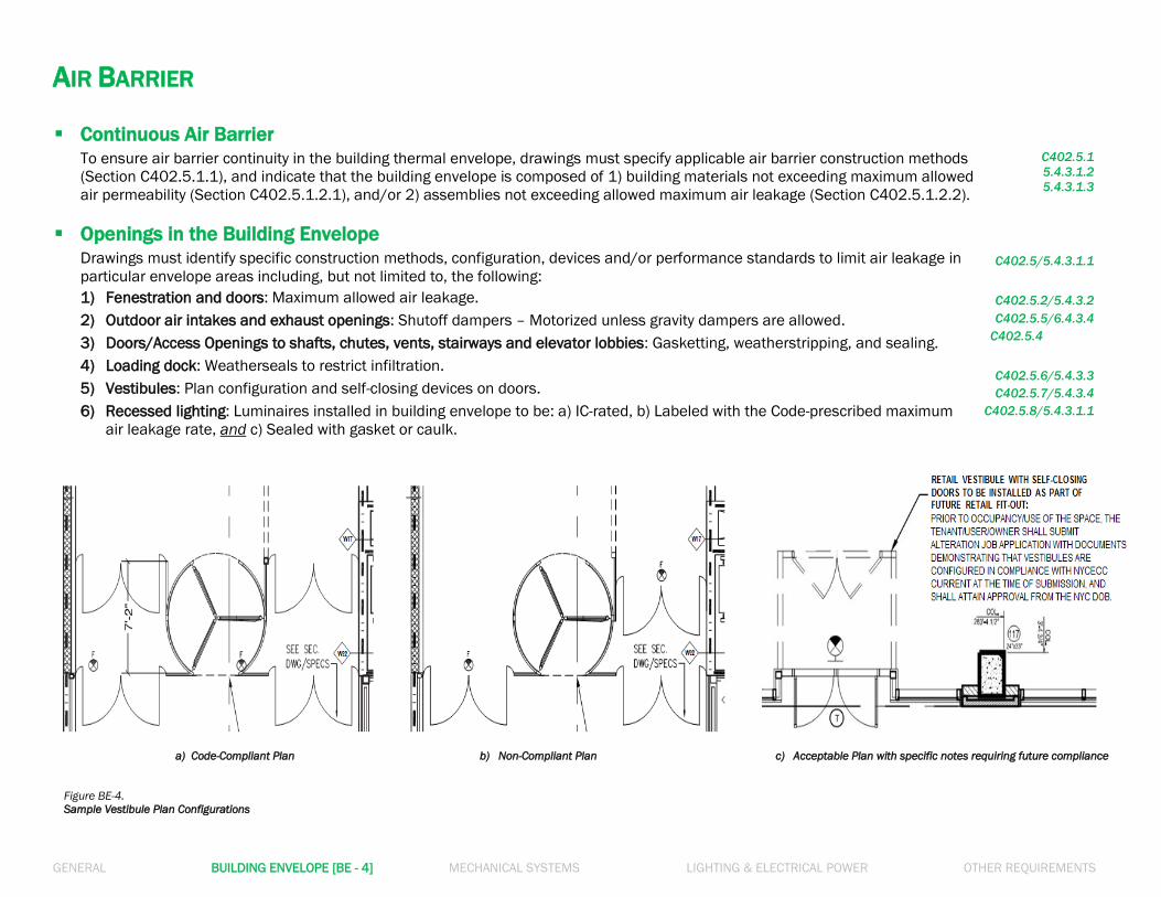
Openings in the Building Envelope
Drawings must identify specific construction methods, configuration, devices and/or performance standards to limit air leakage in
particular envelope areas including, but not limited to, the following: C402.5/5.4.3.1.1
1) Fenestration and doors: Maximum allowed air leakage.
2) Outdoor air intakes and exhaust openings: Shutoff dampers – Motorized unless gravity dampers are allowed.
3) Doors/Access Openings to shafts, chutes, vents, stairways and elevator lobbies: Gasketting, weatherstripping, and sealing.
4) Loading dock: Weatherseals to restrict infiltration.
5) Vestibules: Plan configuration and self-closing devices on doors.
6) Recessed lighting: Luminaires installed in building envelope to be: a) IC-rated, b) Labeled with the Code-prescribed maximum
air leakage rate, and c) Sealed with gasket or caulk.
C402.5.2/5.4.3.2
C402.5.5/6.4.3.4
C402.5.4
C402.5.6/5.4.3.3
C402.5.7/5.4.3.4
C402.5.8/5.4.3.1.1
a) Code-Compliant Plan b) Non-Compliant Plan c) Acceptable Plan with specific notes requiring future compliance
Figure BE-4.
Sample Vestibule Plan Configurations
GENERAL BUILDING ENVELOPE [BE - 5] MECHANICAL SYSTEMS LIGHTING & ELECTRICAL POWER OTHER REQUIREMENTS
AIR LEAKAGE TESTING & AIR BARRIER CONTINUITY PLAN Whole Building Air Leakage Testing
- For new Residential buildings, mandatory air leakage testing must be specified to ensure the air leakage rate does not exceed 3
air changes per hour (3 ACH) at 50 Pascals.
- For Residential buildings with 2 to 7 dwelling units within the building envelope, and with 8 or more dwelling units within the
building envelope, drawings may identify alternate testing procedures of sample “testing unit” verification methods as specified in
the Code.
- For new Commercial buildings 25,000 to 49,999 sf in the conditioned space floor area, and 75 ft or less in height, mandatory air
leakage testing must be specified to ensure the air leakage rate does not exceed 0.4 cfm/ft2 of envelope area at 75 Pascals.
R402.4.1.2
R402.4.1.3
C402.5.1.3
5.4.3.5
Air Barrier Continuity Plan
- For new Commercial buildings 50,000 sf or greater in the conditioned space floor area, an Air Barrier Continuity Plan must be
prepared and implemented.
- The Air Barrier Continuity Plan must specify (1) List of typical joint and seam conditions, (2) Testing method options for each, (3)
Sampling rates of test, (4) Quality control process in test, and (5) Guidelines for test reports and final certificates.
C402.5.1.3
5.4.3.5
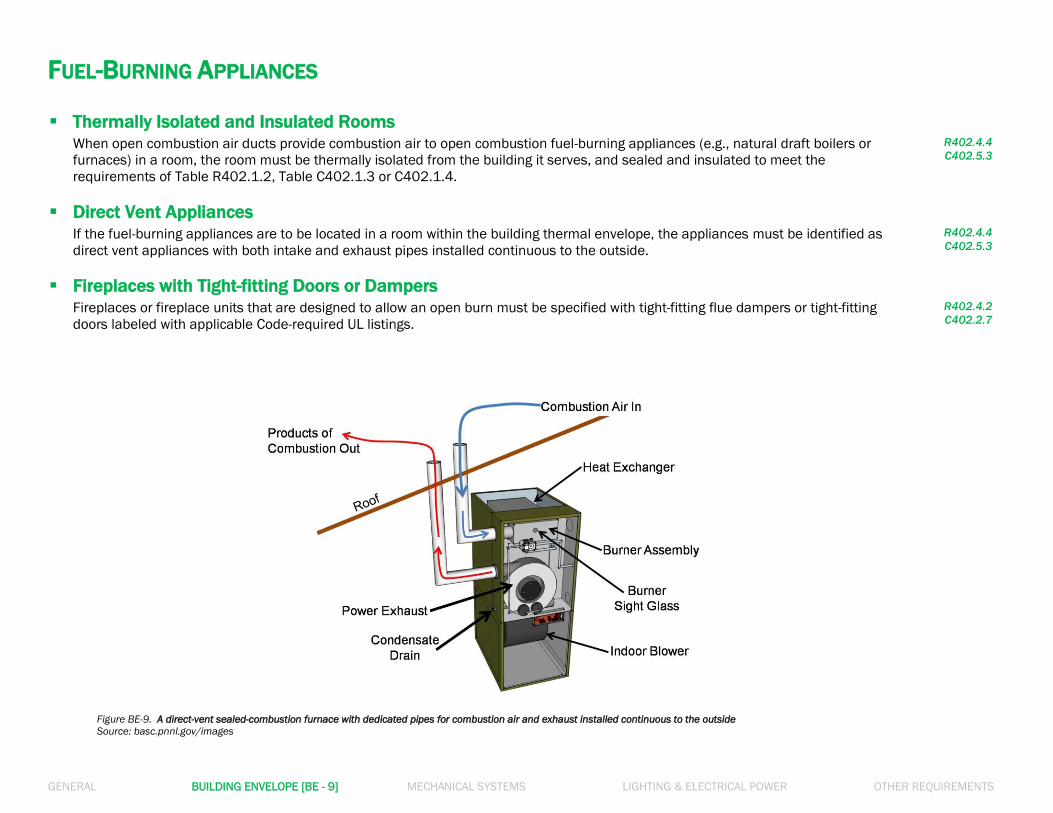
Figure BE-5. Blower door installed for air leakage testing at a construction site
GENERAL BUILDING ENVELOPE [BE - 6] MECHANICAL SYSTEMS LIGHTING & ELECTRICAL POWER OTHER REQUIREMENTS
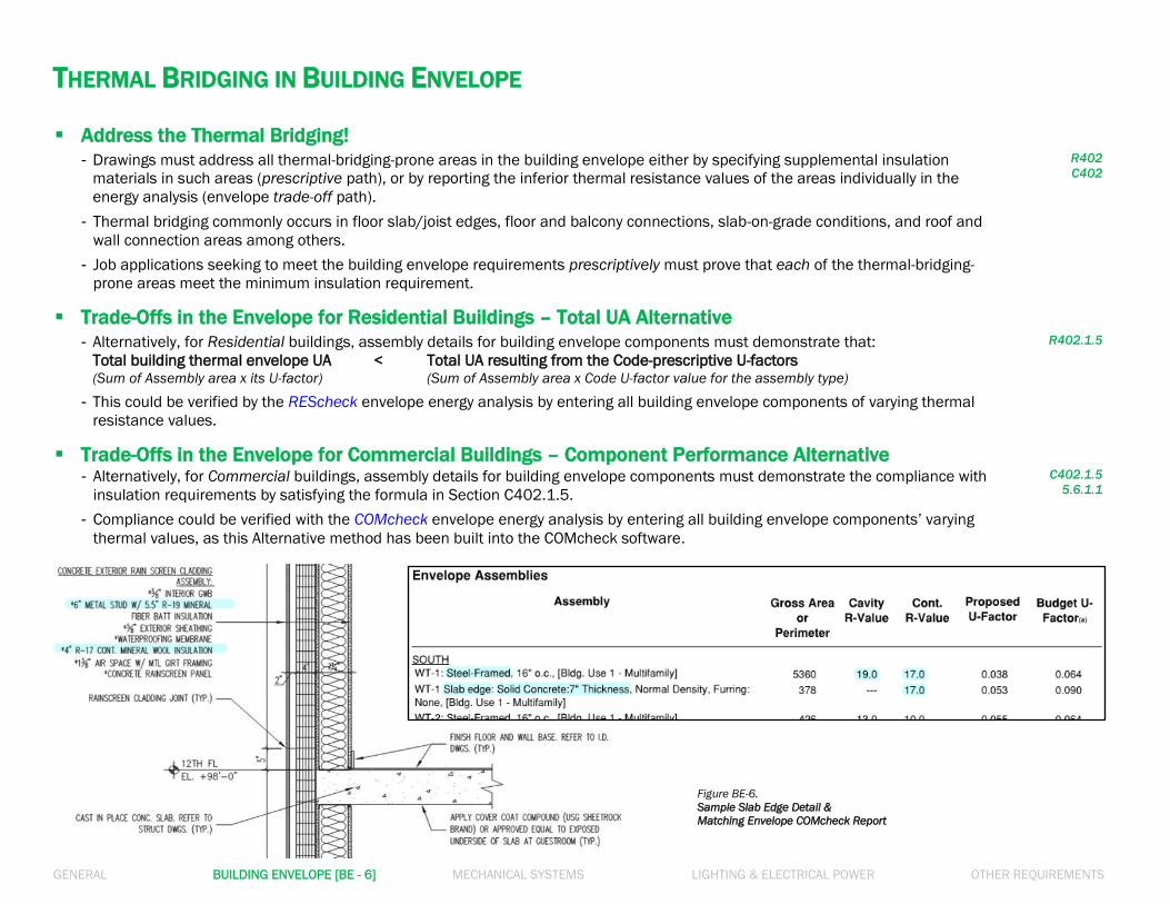
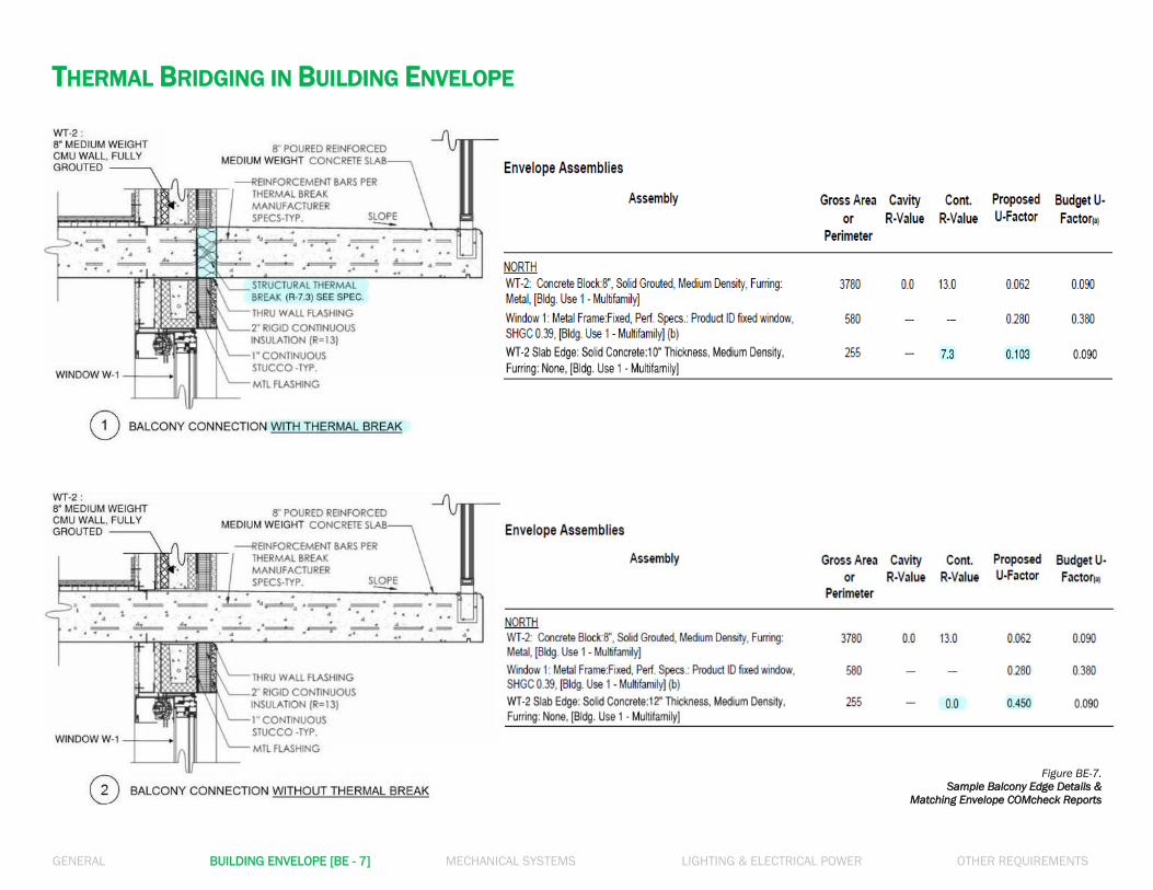
THERMAL BRIDGING IN BUILDING ENVELOPE Address the Thermal Bridging!
- Drawings must address all thermal-bridging-prone areas in the building envelope either by specifying supplemental insulation
materials in such areas (prescriptive path), or by reporting the inferior thermal resistance values of the areas individually in the
energy analysis (envelope trade-off path).
- Thermal bridging commonly occurs in floor slab/joist edges, floor and balcony connections, slab-on-grade conditions, and roof and
wall connection areas among others.
- Job applications seeking to meet the building envelope requirements prescriptively must prove that each of the thermal-bridging-
prone areas meet the minimum insulation requirement.
R402
C402
Trade-Offs in the Envelope for Residential Buildings – Total UA Alternative
- Alternatively, for Residential buildings, assembly details for building envelope components must demonstrate that:
Total building thermal envelope UA < Total UA resulting from the Code-prescriptive U-factors (Sum of Assembly area x its U-factor) (Sum of Assembly area x Code U-factor value for the assembly type)
- This could be verified by the REScheck envelope energy analysis by entering all building envelope components of varying thermal
resistance values.
R402.1.5
Trade-Offs in the Envelope for Commercial Buildings – Component Performance Alternative
- Alternatively, for Commercial buildings, assembly details for building envelope components must demonstrate the compliance with
insulation requirements by satisfying the formula in Section C402.1.5.
- Compliance could be verified with the COMcheck envelope energy analysis by entering all building envelope components’ varying
thermal values, as this Alternative method has been built into the COMcheck software.
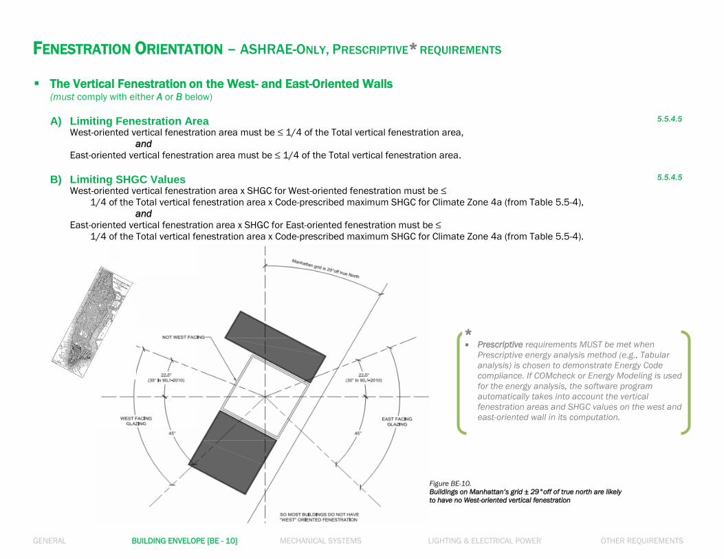
The Vertical Fenestration on the West- and East-Oriented Walls
(must comply with either A or B below)
A) Limiting Fenestration Area 5.5.4.5
West-oriented vertical fenestration area must be ≤ 1/4 of the Total vertical fenestration area,
and
East-oriented vertical fenestration area must be ≤ 1/4 of the Total vertical fenestration area.
B) Limiting SHGC Values 5.5.4.5
West-oriented vertical fenestration area x SHGC for West-oriented fenestration must be ≤
1/4 of the Total vertical fenestration area x Code-prescribed maximum SHGC for Climate Zone 4a (from Table 5.5-4),
and
East-oriented vertical fenestration area x SHGC for East-oriented fenestration must be ≤
1/4 of the Total vertical fenestration area x Code-prescribed maximum SHGC for Climate Zone 4a (from Table 5.5-4).
Prescriptive requirements MUST be met when
Prescriptive energy analysis method (e.g., Tabular
analysis) is chosen to demonstrate Energy Code
compliance. If COMcheck or Energy Modeling is used
for the energy analysis, the software program
automatically takes into account the vertical
fenestration areas and SHGC values on the west and
east-oriented wall in its computation.
*
Figure BE-10.
Buildings on Manhattan’s grid ± 29°off of true north are likely
to have no West-oriented vertical fenestration
GENERAL BUILDING ENVELOPE [BE - 11] MECHANICAL SYSTEMS LIGHTING & ELECTRICAL POWER OTHER REQUIREMENTS
RESIDENTIAL BUILDING ENVELOPE Blown or Sprayed Roof/Ceiling Insulation
- The thickness of blown-in or sprayed roof/ceiling insulation (fiberglass or cellulose) in the attic must be indicated on markers for
every 300 sf.
- The markers must indicate minimum initial installed thickness with numbers of a minimum of 1 inch in height.
R303.1.1.1
Protection of Exposed Foundation Insulation
Rigid, opaque and weather-resistant protective coverings must be applied to protect the insulation over the exterior of basement
walls, crawl space walls and the perimeter of slab-on-grade floors.
R303.2.1
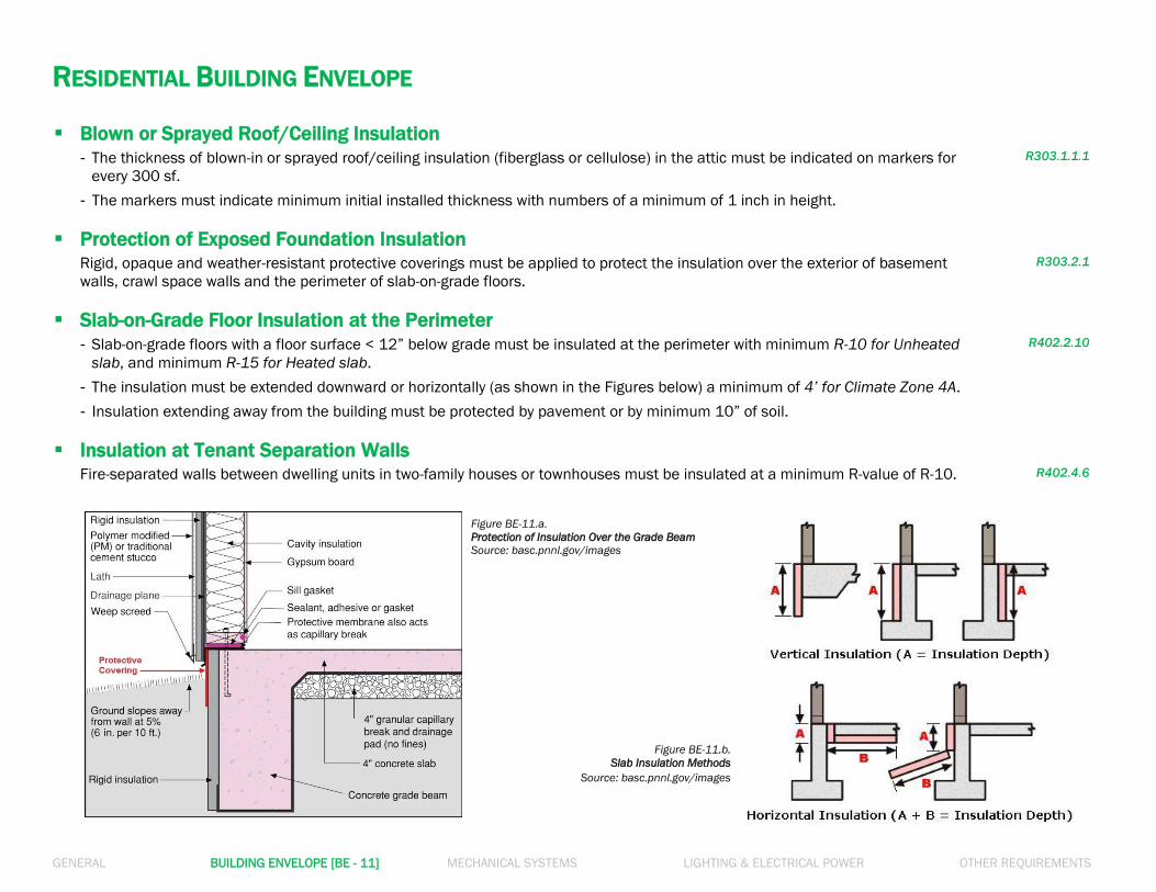
Slab-on-Grade Floor Insulation at the Perimeter
- Slab-on-grade floors with a floor surface < 12” below grade must be insulated at the perimeter with minimum R-10 for Unheated
slab, and minimum R-15 for Heated slab.
- The insulation must be extended downward or horizontally (as shown in the Figures below) a minimum of 4’ for Climate Zone 4A.
- Insulation extending away from the building must be protected by pavement or by minimum 10” of soil.
R402.2.10
Insulation at Tenant Separation Walls Fire-separated walls between dwelling units in two-family houses or townhouses must be insulated at a minimum R-value of R-10.
R402.4.6
Figure BE-11.b.
Slab Insulation Methods
Source: basc.pnnl.gov/images
Figure BE-11.a.
Protection of Insulation Over the Grade Beam
Source: basc.pnnl.gov/images
GENERAL BUILDING ENVELOPE [BE - 12] MECHANICAL SYSTEMS LIGHTING & ELECTRICAL POWER OTHER REQUIREMENTS
RESIDENTIAL BUILDING ENVELOPE
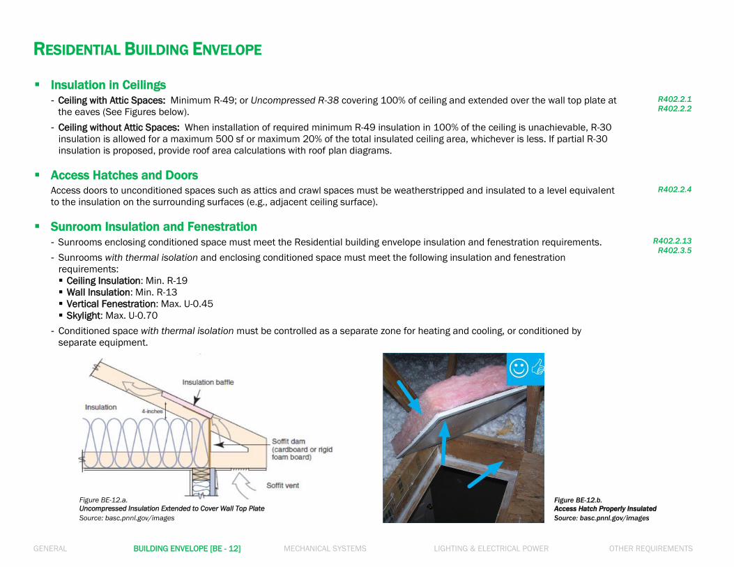
Insulation in Ceilings
- Ceiling with Attic Spaces: Minimum R-49; or Uncompressed R-38 covering 100% of ceiling and extended over the wall top plate at
the eaves (See Figures below).
- Ceiling without Attic Spaces: When installation of required minimum R-49 insulation in 100% of the ceiling is unachievable, R-30
insulation is allowed for a maximum 500 sf or maximum 20% of the total insulated ceiling area, whichever is less. If partial R-30
insulation is proposed, provide roof area calculations with roof plan diagrams.
R402.2.1
R402.2.2
Access Hatches and Doors
Access doors to unconditioned spaces such as attics and crawl spaces must be weatherstripped and insulated to a level equivalent
to the insulation on the surrounding surfaces (e.g., adjacent ceiling surface).
R402.2.4
Sunroom Insulation and Fenestration
- Sunrooms enclosing conditioned space must meet the Residential building envelope insulation and fenestration requirements.
- Sunrooms with thermal isolation and enclosing conditioned space must meet the following insulation and fenestration
requirements:
Ceiling Insulation: Min. R-19
Wall Insulation: Min. R-13
Vertical Fenestration: Max. U-0.45
Skylight: Max. U-0.70
- Conditioned space with thermal isolation must be controlled as a separate zone for heating and cooling, or conditioned by
separate equipment.
R402.2.13
R402.3.5
Figure BE-12.a.
Uncompressed Insulation Extended to Cover Wall Top Plate