48
How to Install D3000

How to Install D3000

Scope of Presentation
• This presentation is intended for both experienced field personnel familiar with warewashing installations, as well as new field service personnel who have only a rudimentary knowledge of accessing triggers and conductivity control.
• The objective is to train the installer to be able to install a UniView control dispenser on either a door or conveyor dishwashing machine, and troubleshoot any unusual conditions they may encounter. To train new installers, we recommend using this presentation in conjunction with an actual installation or at least a lab installation followed by a site visits to see typical conveyor and door machine installations.
• Excluded from this presentation is detailed training on electrical safety, which should always be performed prior to attempting any high voltage installations. In brief, however, power to the dishwasher and dispenser should be shut off at the source prior to opening them, and a voltmeter should be used to verify the power’s off prior to doing wiring.

• D-Series feature comparison
• Physical installation: mounting, tubing, solenoid water supply
• Wiring: power connection, trigger/signal wiring
• Tank titration
• Programming
• Learning algorithm: how it works and as a sales tool
• Alarms & troubleshooting
This presentation consists of the following sections

Features D3000 D1000 D950 D750 D500T D500C D250Maximum # of products 3 3 2 2 2 2 1
Third product capability x x
Time detergent mode x x x x x
Speed mode x x x x
Speed mode (rinse only) x x x x x x
Time + speed mode simultaneously x
Conductivity x x x x
Uniview programming x x x
Potentiometer programming x x x x x
Self-learning detergent feed algorithm x x x
Fixed detergent reduced feed rate x
Probe pulse drive x x x x
Overfeed stop x x x
C3M x x
Low conductivity resistor x
Temperature compensation x x
Rinse delay x x x
Rinse run time limit, F=fixed or P=program P P P F
Datalogging capability x x x
External transformers x
Solenoid capability (detergent only) x x x x
Internal alarm x x x
Alarm output voltage x x x
Drum lance+setpoint alarm triggers x x
Power wires factory installed x x
Prime buttons x x x x x x x
D-Series Feature Comparison

• Pick a spot to the pumpbox(s) on the wall over the dish tray counter or behind the washer; the former is preferred so it’s easy for the dishwashers to see and react to alarms.
• For solid or powder detergent capsule bowls, be sure to install in a location where it’s easy for the dishwashers to check and replace the capsule.
Mounting Location

• Connect tubes to standpipes as shown at left. The standpipes come with nut fittings to connect to standard 1/4” ID detergent/sanitizer and 1/8” ID rinse polyflow transport tubing
• For installations requiring a low level alarm lance, you can either use a separate low level lance, or a low level suction lance such as 1201071 which clamps onto the side of the drum
• If you want to use color transport tubing, use ¼” OD blue polyflow 092384, ¼” OD red polyflow 041771, and 1/4T -1/4T compression fitting rinse tube 1205464, and the detergent standpipe 035623
035623 Detergent 1/4” ID 18” long CPVC standpipe
050572 Rinse 1/8” ID 18” long CPVC standpipe
TUBING: Chemical Pickup Lance Connection

• The left side of the pump is the suction side which should be connected to the chemical supply
• The right side of the pump is the chemical discharge side which will be connected to injection fittings on the washer
• Flex tubes are shipped outside of the cartridge so they don’t seal shut during warm storage
• Loosen tube nuts, insert tubes, and tighten nuts as shown
• Always point black SnapHead pins up or down and push in to lock into place
TUBING: Pump Connection

• Mount the detergent bulkhead fitting in a 7/8” hole above the water line, just above where the probe will be located. Make surethe area has plenty of water circulation, such as an area near the wash pump strainer inlet so the detergent will get circulated immediately.
• Add 1/8” rinse injector (and any ¼” sanitizer injector) to rinse linein a location away from large amounts of steam or moving parts which can induce thermal or physical fatigue on injector plasticover time.
• If using a pressure switch, an injector with two connections is required, one for the rinse and one for the sanitizer or copper tubing line to the pressure switch. We recommend using a stainless steel injection fitting if installing in a remote location, since they are impervious to thermal and physical fatigue.
• Tubes connect to the fittings just like they do to pump nuts.Don’t use an old hole if it’s in the wrong spot! Making a new hole during installation always takes less time than getting a trouble call and making a new hole on a separate trip
1/8” Rinse Injection Fitting 0514671/4” Sanitizer Inj. Fitting 051466
Bulkhead Fitting for bowls 035542Note: liquid detergent fitting 022031 comes with a ¼” compression nut fitting. Solid/powder bowls use a 5/8” barb fitting 035542.
TUBING: Injection Fittings

• Connect water supply tube to water inlet on bottom of solenoid. Be sure to verify which way the arrows point on the solenoid, since standard warewash solenoids have the water inlet on the bottom whereas OPL solenoids have it on the top.
• Connect outlet to bowl
• Mount bowl in a location where it will be easy for the kitchen workers to replace the detergent capsule
Solenoid & Bowl

• Connect detergent trigger wires to “DETERGENT” and rinse solenoid wires to “RINSE”, connecting one wire to HOT and the other to the appropriate voltage (use 115 for 90-115V, and 230 for voltages a bit over 230)
• WHT & BLK = 120V 50/60 Hz
• WHT& RED = 230V 50/60 Hz
• If you want to inject both detergent and rinse using the rinse solenoid during the rinse cycle, connect the trigger signal to one side of the terminal block and jump the signal to the other side.
If using a pressure switch, connect it to the +RINSE green PCB connection
Terminal block before connecting power wires
Terminal block after connecting power wires
WIRING: Trigger Connection

• Put any low level drum lances(#1201188 or 1202071) into the chemical drums
• Connect wires from the lance sensor to the pressure switch J5 connection on the PCB
• The dispenser will automatically sound an alarm when the low level alarm has a contact closure
• The alarm can be silenced by replacing the chemicals
OPTIONAL WIRING: Low Level Alarm

• Mount conductivity probe 3-4 inches (8-10 cm) under the water line, about 3”-5”/7-12cm under the detergent injection point and as close to the wash pump intake strainer as possible. The terminals should be vertically oriented as shown.
• Note: Some shallow tanks have probe holes on the wall, but when pots run through they can carry out so much of the rinse water that the water level may drop over 4”(10CM)/below the probe hole; in these cases mount the probe through the bottom of the washer.
• Ensure the probe location is not close to heater elements, corners, or in the path of moving mechanical components. Ensure the probe location is in an area with plenty of circulation
• Connect probe wires to COND input. If using a temperature compensated probe, run the thermistor/temperature wires to the TEMP input
• Probe wires can be run out of the pumpbox with low level wires since they don’t emit electrical noise, but they must be separated from noisy power and trigger wires
Be sure you do not mount the probe in an old hole that’s a bad location, since that can produce bad probe readings or subject the probe to too much thermal shock
WIRING: Probe Connection

• Press the button on the left to prime the detergent
• Press the button on the right to prime the rinse
• Press both buttons to prime any sanitizer
Prime the Pumps

PotentiometerProgramming• Use the switch to select COND for probe mode, or TIME for probeless mode
•Turn the knobs to determine settings as noted below
Knob Conductivity Mode Time Mode
DETERGENT SETPOINT
Concentration Set Point 0-70 Beta Units
Detergent Recharge 0-30 Seconds at 99% speed
RINSE SETTING
Rinse Speed 0-99% while trigger is on
Rinse Run Time 0-30 sec
DET INITIAL CHARGE
Detergent Initial Charge 0-90 seconds

UniviewProgramming
When any value rises above 99, the LCD will indicate +100 or +200 in the upper right. When a value is set outside the valid range, it will be rejected and the minimum or maximum will be displayed and used. Pressing the send key when viewing a read-only menu such as the probe reading will cause the programmer to display “EE”. If you change a value and then press the menu key without pressing send, the check mark will flash to remind you to press send before changing the menu#; pressing a menu button twice will change the menu selected without saving the new setting.
• Before programming, you must change menu 23 from knob control “0” to Uniview control “1”.
• Hold down data up/data down to change a value by increments of 10.
• A check mark appears above the Menu Number whenever a setting has been changed but not saved.
• Remember to push the “send” button after changing a setting, or it will not be saved.

• Use the DATA UP and DATA DOWN keys on the Uniview to set the number to 1 for Probe Mode, 2 for Probeless Timed Mode or 3 for Probeless Speed Mode
• So, screen will read:
• 1 1 = Probe mode
• 1 2 = Probeless time mode
• 1 3 = Probeless speed mode (only recommended for special installs by advanced users)
Programming: Mode Selection

• 1 = Conveyor dishmachine
• 2 = Door machine (power on when chemical needed)
Programming: Machine Type

• This screen displays the probe conductivity reading in Beta Units, including VCP correction for any scale or partial short– “Lo” is displayed if the contact is
open and there is no reading.– “Hi” is displayed if the contact is
closed or there’s a short.
• In the example shown, the reading is 53 Beta Units.
Programming: Conductivity ReadingProbe mode only
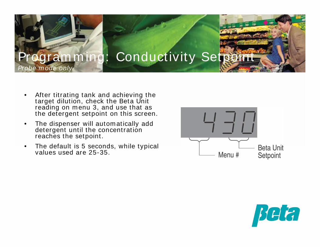
• After titrating tank and achieving the target dilution, check the Beta Unit reading on menu 3, and use that as the detergent setpoint on this screen.
• The dispenser will automatically add detergent until the concentration reaches the setpoint.
• The default is 5 seconds, while typical values used are 25-35.
Programming: Conductivity SetpointProbe mode only
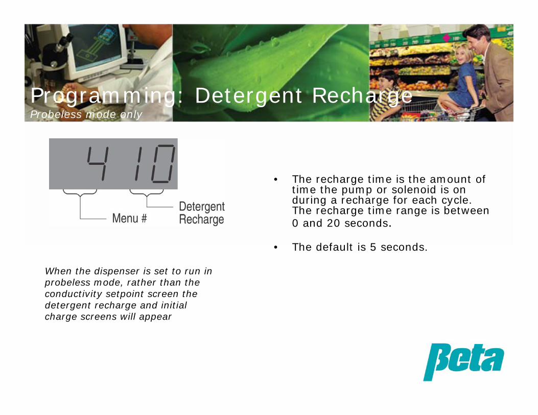
• The recharge time is the amount of time the pump or solenoid is on during a recharge for each cycle. The recharge time range is between 0 and 20 seconds.
• The default is 5 seconds.
When the dispenser is set to run in probeless mode, rather than the conductivity setpoint screen the detergent recharge and initial charge screens will appear
Programming: Detergent RechargeProbeless mode only

• The initial charge is the amount of time the detergent pump or solenoid will be on when filling an empty tank.
• This initial charge will occur 20 seconds after the power is applied and after the normal recharge. Its purpose is to get the wash tank concentration up quickly. For single-tank, probeless systems, input a time between 0 and 240 seconds. Use the DATA UP and DATA DOWN keys to input the initial charge time, then press SEND.
• The example displays an initial charge time of 60 seconds. The default is 30. For probeless dump and fill
systems, input a 0 (initial charge is not used).
Programming: Initial ChargeProbeless mode only

• The rinse delay is the time between when the dispenser receives a signal that the rinse cycle has begun, and when it begins pumping chemical.
• The rinse delay range is 0 to 240 seconds. Use the DATA UP and DATA DOWN keys to input the appropriate delay time, then press SEND.
• The example shows a rinse delay of 10 seconds. The default is 0 seconds.
Programming: Rinse Delay

• The rinse speed refers to the percentage of total pump speed (0 - 99). Use the DATA UP and DATA DOWN keys to input a percentage, then press SEND.
• The example shows the rinse speed at 30%. The default is 10%.
Programming: Rinse Speed

• CONVEYOR MACHINE: – When machine type conveyor is
elected, rinse will run continuously after rinse delay time, and this menu will show a rinse time of 0.
• DOOR MACHINE: – This screen sets the maximum
rinse runtime, 0 to 240 seconds. – Use the DATA UP and DATA
DOWN keys to set a rinse run time, then press SEND.
Programming: Rinse Runtime LimitDoor machine only

• Wash tank temp is displayed in Co.
– “Lo” indicates the contact is open and no temp reading is available
– “Hi” indicates the contact is closed and no temp reading is available
• Use the chart on the right if you need to convert Co to Fo
Celsius Fahrenheit30 8635 9540 10445 11350 12255 13160 14065 14970 15880 17690 194
Programming: Wash Tank Temperature ReadingProbe mode only
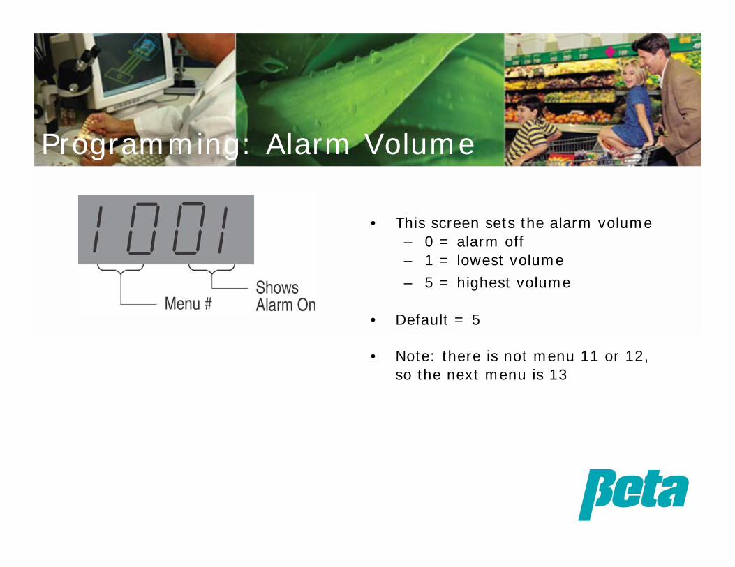
• This screen sets the alarm volume– 0 = alarm off– 1 = lowest volume
– 5 = highest volume
• Default = 5
• Note: there is not menu 11 or 12, so the next menu is 13
Programming: Alarm Volume

• This menu sets the speed from 0 to 99%.
• The purpose of this control is to adjust the pump to best suit the viscosity of the product to be delivered.
• The example shows a pump speed of 50% of maximum. Always use a speed of 99%, the
default, with a solenoid or it will turn on & off continuously
Programming: Detergent Pump Speed

• Sanitizer can be set to feed with the rinse (by inputting a 0) or with detergent (by inputting a 1). – 0 = Sanitizer runs with rinse– 1 = Sanitizer runs with detergent– 2 = Sanitizer runs with rinse, low level
alarm stops pumps– 3 = Sanitizer runs with detergent, low
level alarm stops pumps– 4 = Sanitizer runs with rinse, pumps
continue running despite low level alarm – 5 = Sanitizer runs with detergent, pumps
continue running despite low level alarm
• Use the DATA UP and DATA DOWN keys to select 1 or 0, then press SEND.
When set to run with rinse, the sanitizer pump runs at the selected speed during the delay and the rinse cycle. When set to run with detergent, the sanitizer pump runs only when the detergent pump runs.
Programming: Sanitizer Signal & Alarm LogicIgnore this menu if using a 2 product system without low level lance

• This screen sets the sanitizer pump speed from 0-99%
• In the example shown, the speed is set to 15%
• The default setting is 0. Note you must use Uniview programming and modify this setting to run a sanitizer pump with a D3000.
Programming: Sanitizer SpeedIgnore this menu if using a 2 product system

• Displays PCB version– 5 = Current 3 mode D3000 PCB
Programming: PCB ID CodeIgnore this menu except during troubleshooting

• The rack count goes up every time the rinse pump turns on when running with a door machine, or every 20 seconds with a conveyor.
• Because the Uniview display is small, the rack count is displayed across screens 17,18, & 19. Together, the following screens show a rack count of 1,251,672.
Programming: Rack CountsMenus 17-19
19 displays digits for the values in the 10’s and 1’s. This screen shows a value of 72.
18 displays digits for the values in the 1,000’s and the hundreds. This screen shows a value of #,##1,6##
17 displays digits for values in the millions, hundred thousands, and ten thousands. This screen shows a value of 1,25#,###

• This screen shows the drain count, from 0-240
• The count resets after 240
• The objective on including this screen is to be able to check if an account is draining the tank enough
Programming: Drain CountConductivity Mode Only

• This screen sets the conductivity range, either at the default level of 1 for hi/standard conductivity range, or 0 for low conductivity range
• The default is 1
• Generally speaking the low conductivity range is only used in Japan
Programming: Conductivity RangeConductivity Mode Only

• This screen shows the conductivity reading from the probe, without the VCP correction, so you can tell the difference between the corrected reading and the normal reading a different dispenser might provide
• In the example on the right the conductivity reading is 60 Beta Units, which would cause a trouble call in most accounts. Here., because VCP corrects for probe scale, the dispenser can keep functioning normally without causing a trouble call
Programming: Conductivity Reading without VCP CorrectionConductivity Mode Only

• This screen determines whether the dispenser will use the potentiometer and switch settings on the PCB of the digital Uniview settings to run the pumps.
• 0=Knobs/Dial & switch control from the PCB
• 1=Uniview programmed setting control
• Default =0 so the unit can be setup without a Uniview
This screen must be changed from 0 to 1 in order to send any settings to the dispenser. This screen is the first programming step.
Programming: Control Source
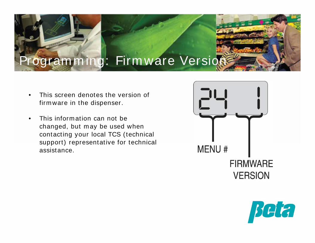
• This screen denotes the version of firmware in the dispenser.
• This information can not be changed, but may be used when contacting your local TCS (technical support) representative for technical assistance.
Programming: Firmware Version
1. Check water hardness: Water hardness effects the amount of detergent that must be added, so you should check water hardness in the account:
a. Get 10 ml sample of waterb. Add 3-5 drops of buffer solutionc. Add 2/3 scoop of indicator powderd. Swirl, adding single drops of hardness reagent e. Count drops until color changesf. 1 drop=0.5 grain hardness
Tank Titration: Step 1 =Check Water Hardness
2. If in probe mode, make the UniView setpoint 0 or short the probe wires to keep the unit from alarming.
3. Fill tank and use prime button to add some detergent so you can titrate the tank. If it’s a probeless installation, use a stopwatch to count the seconds of pump on time so you can program initial charge.
a. Take sample of tank water in 10 ml vialb. Add 3-5 drops of Phenolphthalein solutionc. Swirling vial around in circles to mix, add sulfuric acid drop by drop,
counting the dropsd. Compare to the chart on the following page:
WEIGHT/PRODUCT FACTOR=TARGET # DROPS•If more drops required than the result, add more detergent•If less drops required than the test result, decrease the amount of detergent•When you’ve reached the right number of drops, check the Beta Unit reading and use that as the setpoint; if in time mode, use the seconds counted on the stopwatch for initial charge.Note: Be sure to follow the directions in your titration kit, in case they differ from those above.
Tank Titration:Step 2 = Titrate for setpoint & tank fill

Once you’ve determined the number of seconds to run the initial charge, and the tank is titrated to the correct concentration, you can titrate for the recharge amount:
4. Turn dispenser off, and run a rack through the dishmachine.
5. Once again, use a stopwatch and press the prime button for a couple seconds to allow detergent to feed, and retitrate until you know the correct number of seconds to restore the correct detergent concentration to the tank. Use this number of seconds in UniView menu 4 detergent recharge.
Tank Titration:Step 2 = Titrate for rechargeProbeless mode only

Weight of Products 0.1 0.15 0.2 0.25 0.3Product Factor Drops of SolutionUnipak G1 0.007 14 21 29 36 43Unipak G3 0.008 13 19 25 31 38Diverpak 0.008 13 19 25 31 38Precision Advantage 0.009 11 17 22 28 33Encapsulated dish detergent Plus 0.01 10 15 20 25 30Powder Keg 0.01 10 15 20 25 30Declare Plus 0.01 10 15 20 25 30Advance Dish Det 0.01 10 15 20 25 30Encapsulated Dish Det Metal Safe 0.011 9 14 19 23 28Diversey Pep 0.011 9 14 19 23 24Salute 0.013 8 12 16 20 20Unipak G7 0.015 7 10 13 16 20Elect 0.015 7 10 13 16 17Depth Charge 0.018 6 8 11 14 13Eclipse 0.024 4 6 8 11 12Epoch 0.026 4 6 8 10 11Low Energy Det 0.028 4 5 7 9 10Perform 0.029 3 5 7 9 10DiverForce L4 0.029 3 5 7 9 10Serve 0.029 3 5 7 9 9Slurry 0.033 3 5 6 8 8Rotate Plus 0.036 3 4 6 7 8Liqua-Safe 0.036 3 4 6 7 7Lustral 0.042 2 4 5 6 7Adv. Liq Power 0.042 2 4 5 6 7

Troubleshooting & FAQ
Solutions to potential installation and maintenance issues

Probe Reading Solution
LO (00)
No reading usually means the wires aren’t properly connected. Check all the wire connections , and the wire itself for damage. If everything’s hooked up correctly, the problem could be delam ination; to check for this detach wires from probe, attach both voltmeter wires (use ohm setting) to one probe post, with one wire on the sensor s ide, one wire on the screw/wire attachm ent s ide to verify continuity. Repeat for the second post. Scrap probe if there's no continuity, and verify probe location meets guidelines before ins talling a new one
Too low, overdos ingCheck tank for extreme scale build up. If there’s a lot of scale, clean the probe.
Too high, not dos ing enough
Replace the probe. This failure should only be seen on pre-Y2K temperature compensated probes. Newer temp comp probes are medical grade and shouldn’t fail in this manner.
HI (99)
This failure usually indicates a short. Check the wires to ensure there’s no short, and check the back of the probe for mois ture. Sometimes if the probe is wet in back, replacing it and allowing it to dry will allow it to function again. In rare cases mois ture may work into the body of the probe; when this occurs the probe can’t be dried out and ins tead must be scrapped.
Probe Troubleshooting Chart

1. Is there a mechanical problem with a motor or solenoid? Note that a worn out gearbox can draw too much current and blow the fuse.
2. Do motor and/or solenoid resistance measurements fall in the approximate range from 4 to 100 ohms? If yes, go on to the next step. If no, replace suspect part(s) since a shorted motor or solenoid will cause the fuse to blow.
Measure resistance only when the power is turned off. A short will typically measure less than 0.2 ohms; an open will typically measure more than 2000 ohms.
3. Are proper voltages measured across the appropriate output terminals (detergent drive and rinse drive) when power is applied? If not, replace the PCB. Maximum voltage is 33 to 34 VDC (without load). Rinse voltages may be lower depending on the speed setting.
Properly Rated Fuse Blows Repeatedly

Menu Conductivity Mode Timed Mode 1 1 2
21 - Conveyor 2 - Door
1 - Conveyor 2 - Door 3 - Door with external
3VCP Concentration Reading
- - -
4Concentration Set Point 0-70
Detergent Recharge 0-20 seconds
5 - - -Detergent Initial Charge 0-240 seconds
6 Rinse Delay 0-240 sec Rinse Delay 0-240 sec
7 Rinse Speed 0-99% Rinse Speed 0-99%
8Rinse Run Time Limit 0-240 sec
Rinse Run Time Limit 0-240 sec
9Wash Temp 0-100 degrees C
- - -
10Alarm Volume 0 min-5 max
Alarm Volume 0 min-5 max
11 Not used Not used12 Not used Not used
Menu Conductivity Mode Timed Mode
13 Detergent Speed 0-99% Detergent Speed 0-99%
14
15 Sanitizer Speed 0-99% Sanitizer Speed 0-99%
16 PCB ID Code PCB ID Code
17Rack Count High (0-240) 1,000,000's, 100,000's & 10,000's
Rack Count High (0-240) 1,000,000's, 100,000's & 10,000's
18Rack Count Middle (0-99) 1,000's & 100's
Rack Count Middle (0-99) 1,000's & 100's
19Rack Count Low (0-99) 10's & 1's
Rack Count Low (0-99) 10's & 1's
20 Drain Count (0-240) Not available
21Conductivity Range 0 = LO 1 = HI
- - -
22Concentration Reading without VCP
- - -
23Control Source 0 = Knobs/dial control 1 = Uniview control
Control Source 0 = Knobs/dial control 1 = Uniview control
24 Firmware Version Firmware Version
Sanitizer Feed: 0 = on with rinse, 1 = on with detergent, 2 = on with rinse, low level stops all
pumps, 3 = on with detergent, low level stops all pumps
Programming Chart Reference

• The D3000 pumps detergent whenever the detergent input has power and the probe’s conductivity reading indicates wash tank concentration is below setpoint. It feeds up to five times before issuing an alarm.
• These dispensers have a patented learning algorithm which determines the length of the feeds. How does the learning algorithm work?
– It measures how many Beta Units below setpoint the conductivity is
– It pumps about one second per Beta Unit below setpoint on the first feed.
– The second feed duration is calculated by the dispenser, based on the rise in Beta Units per second of pump run time in the first feed.
– The learning algorithm averages the results of the last five feeds to determine the best feed rate to get to setpoint without overshoot averaging
• This learning algorithm provides superior results in terms of maintaining setpoint and preventing overfeeding. It also saves the installer time, because he or she just programs a single setpoint variable instead of four variables: reduced feed rate, low detergent delay, overfeed delay, and setpoint.
Patented Learning Algorithm Logic

• A timed mode dispenser will dose the same amount of chemical whether there’s a light or heavy soil load. This limits effectiveness and causes waste.
• Competitors’ probe mode dispensers have fixed feed rates, which are not capable of adjusting themselves to washing conditions which change moment-by-moment with changes in water pressure and soil load
• The learning algorithm feeds more with heavy soil or increased water pressure, ensuring consistent results!
• The learning algorithm feeds less with light soil or less water pressure, prevent detergent wastage.
1. Heavy soil load dishes still get clean
2. Detergent is wasted on light soil load racks
3. Compensates for different water flowrates, from fluctuating kitchen water pressure
– This second point is frequently mentioned to customers, but whatshocks their customers and impacts their business most is the first point!
Patented Learning Algorithm = Sales Tool

Probe Alarms • Low Detergent Alarm
– Even when performing initial charge, tanks will typically reach setpointwithin the first five feeds. To alert the operator that there’s no more detergent, or the wash tank drain is open, the D3000 will issue an on/off beeping alarm starting on the sixth feed. It will continue pumping another five feeds, with the duration of each feed determined by the learning algorithm. If the dispenser reaches setpoint prior to the end of the tenth feed, the alarm will turn off. To manually reset the alarm as when programming the dispenser, short the probe wires.
• Overfeed Stop Alarm
– As soon as the tenth feed is complete, the dispenser will go into overfeed stop. When it does this, the alarm ceases beeping and becomes a continuous loud sound. While in overfeed stop, the unit cannot be programmed. To cancel the overfeed stop alarm, toggle the power on and off, or short the probe input by connecting the probe + and – terminals. If using a wire to jump the + and – during programming, be sure to remove it after programming or the dispenser will not feed.

• The telephone cable (090358) used on the UNIVIEW displays the following symptoms when the a wire is severed or the socket connection is dubious such that the contact is OPEN:
• Black wire: UNIVIEW display is blank / PCB operates ok.
• Red wire: UNIVIEW reads data but will not send data to PCB / PCB operates ok.
• Green wire: UNIVIEW shows 4 bars on display / PCB operates ok.
• Yellow wire: UNIVIEW display is blank / LED on PCB is always on instead of flashing and no other functions work.
• Menu 11 & 12 don’t appear? Screen 11 & 12 are only used for data reporting (trigger status etc) with the D5000, and thus aren’t displayed on the UniView.
UniView Communication Trouble


