Application Note How to Make PIM over CPRI Measurements With a BTS Master MT8220T Base Station Analyzer PIM over CPRI is Anritsu’s new patented technology that enables users to make PIM measurements on a live system at ground level by monitoring regular LTE traffic carried by an optical fiber connection. By tapping into the CPRI data on the downlink and uplink between the remote radio head (RRH) and baseband unit (BBU), the BTS Master™ MT8220T base station analyzer can calculate the PIM desensitization of the LTE uplink (see Figure 1). This measurement technique tests real-world PIM scenarios, such as self- generated PIM (caused when multiple 15 kHz subcarriers in a single LTE signal mix and create PIM in its own uplink band) as well as 2nd and 3rd order harmonics (e.g., 850 MHz downlink interfering with the 1700 AWS uplink or the 900 downlink interfering with the 1800 uplink). See Figure 2. Since live traffic is being used for this process, there are some inherent differences relative to PIM testing with an RF PIM analyzer. For example, there are no calibrated 43 or 46 dBm two-tone continuous wave (CW) signals used, only the LTE subcarriers and resource blocks (RBs). Rather than measuring a dBc result from CW stimulus, a PIM desensitization value is calculated. PIM desensitization can be thought of as the amount of noise in the uplink signal that is caused by PIM. This measurement is calculated by synchronizing and comparing all available downlink signals of a sector (up to 2x MIMO) against each individual uplink signal. The PIM over CPRI measurement supports SISO, 2x2 MIMO, and 2x4 MIMO. In addition, it will also determine if the PIM found is internal or external to the MIMO antenna system, which is essential when ascertaining if a tower crew needs to be called on site to fix PIM. Figure 1: Typical test set-up for self generated PIM scenarios Figure 2: Typical set-up to measure harmonic PIM, in this example a 850 MHz download generating PIM in a 1,700 MHz uplink
Transcript
Application Note
How to Make PIM over CPRI Measurements With a BTS Master MT8220T Base Station Analyzer
PIM over CPRI is Anritsu’s new patented technology that enables users to make PIM measurements on a live system at ground level by monitoring regular LTE traffic carried by an optical fiber connection. By tapping into the CPRI data on the downlink and uplink between the remote radio head (RRH) and baseband unit (BBU), the BTS Master™ MT8220T base station analyzer can calculate the PIM desensitization of the LTE uplink (see Figure 1). This measurement technique tests real-world PIM scenarios, such as self-generated PIM (caused when multiple 15 kHz subcarriers in a single LTE signal mix and create PIM in its own uplink band) as well as 2nd and 3rd order harmonics (e.g., 850 MHz downlink interfering with the 1700 AWS uplink or the 900 downlink interfering with the 1800 uplink). See Figure 2.
Since live traffic is being used for this process, there are some inherent differences relative to PIM testing with an RF PIM analyzer. For example, there are no calibrated 43 or 46 dBm two-tone continuous wave (CW) signals used, only the LTE subcarriers and resource blocks (RBs). Rather than measuring a dBc result from CW stimulus, a PIM desensitization value is calculated. PIM desensitization can be thought of as the amount of noise in the uplink signal that is caused by PIM. This measurement is calculated by synchronizing and comparing all available downlink signals of a sector (up to 2x MIMO) against each individual uplink signal. The PIM over CPRI measurement supports SISO, 2x2 MIMO, and 2x4 MIMO. In addition, it will also determine if the PIM found is internal or external to the MIMO antenna system, which is essential when ascertaining if a tower crew needs to be called on site to fix PIM.
Figure 1: Typical test set-up for self generated PIM scenarios
Figure 2: Typical set-up to measure harmonic PIM, in this example a 850 MHz download generating PIM in a 1,700 MHz uplink
2
The following steps are required to set-up and conduct a PIM over CPRI measurement using the BTS Master MT8220T base station analyzer. To assist with the process, a single set-up screen (PIM Aid) is provided.
ConnectionsNote: It is always good practice to thoroughly clean your optical fiber connections with a fiber cleaner before installation in order to minimize the chance of introducing contaminants into the optical system.
To perform a single- or multi-carrier PIM over CPRI measurement, an optical tap (or taps for the multi-carrier measurement) must be installed between the BBU and RRH. In many networks, an optical tap is built in to the standard install. If this is not the case, then one must be installed temporarily. To do this, the RRH must first be locked down before disconnecting the fiber to the BBU (this can normally be done with the vendor software installed in the technician’s laptop or by someone at the network operations center [NOC]). Once this is done, the optical tap can be installed between the BBU and RRH.
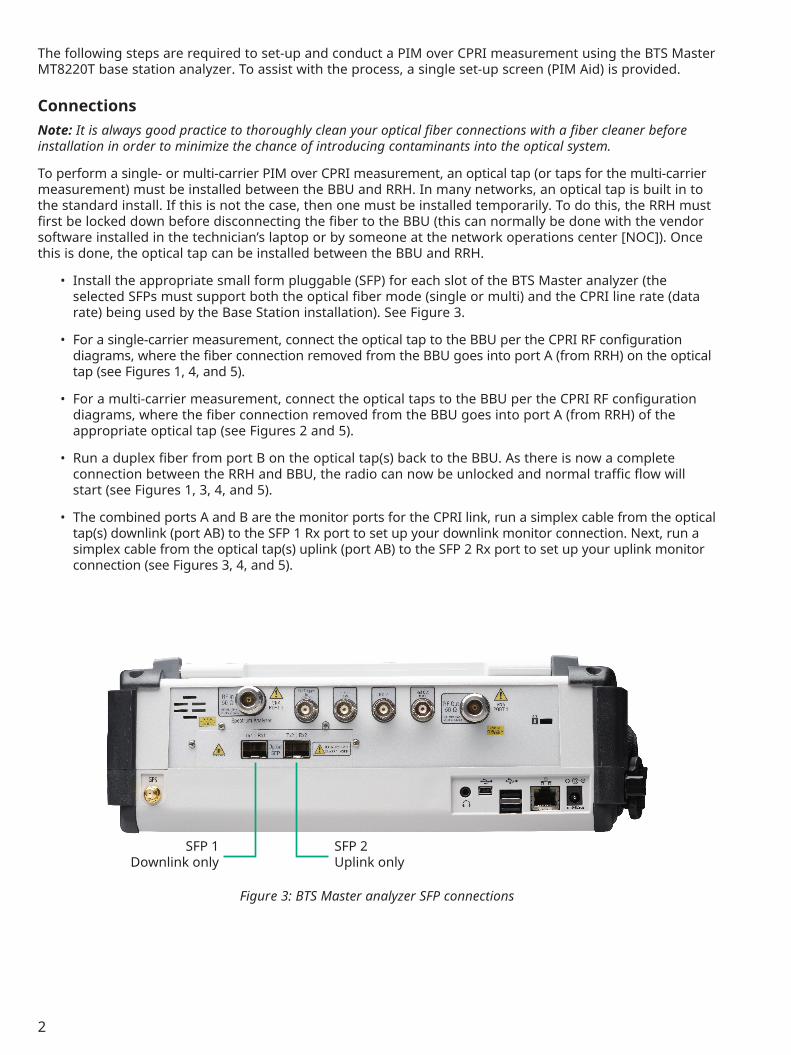
• Install the appropriate small form pluggable (SFP) for each slot of the BTS Master analyzer (theselected SFPs must support both the optical fiber mode (single or multi) and the CPRI line rate (datarate) being used by the Base Station installation). See Figure 3.
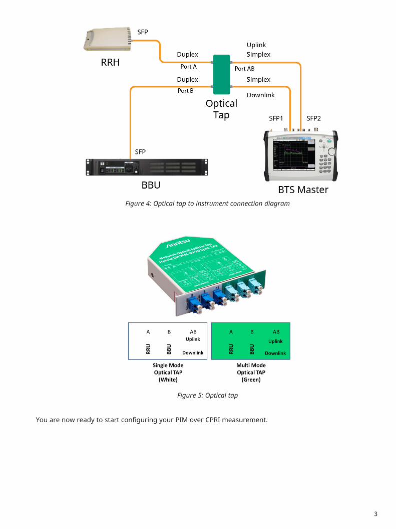
• For a single-carrier measurement, connect the optical tap to the BBU per the CPRI RF configurationdiagrams, where the fiber connection removed from the BBU goes into port A (from RRH) on the opticaltap (see Figures 1, 4, and 5).
• For a multi-carrier measurement, connect the optical taps to the BBU per the CPRI RF configurationdiagrams, where the fiber connection removed from the BBU goes into port A (from RRH) of theappropriate optical tap (see Figures 2 and 5).
• Run a duplex fiber from port B on the optical tap(s) back to the BBU. As there is now a completeconnection between the RRH and BBU, the radio can now be unlocked and normal traffic flow willstart (see Figures 1, 3, 4, and 5).
• The combined ports A and B are the monitor ports for the CPRI link, run a simplex cable from the opticaltap(s) downlink (port AB) to the SFP 1 Rx port to set up your downlink monitor connection. Next, run asimplex cable from the optical tap(s) uplink (port AB) to the SFP 2 Rx port to set up your uplink monitorconnection (see Figures 3, 4, and 5).
SFP 1Downlink only
SFP 2Uplink only
Figure 3: BTS Master analyzer SFP connections
3
You are now ready to start configuring your PIM over CPRI measurement.
Figure 5: Optical tap
Figure 4: Optical tap to instrument connection diagram
4
Put Instrument In To CPRI RF ModeNote: For best results, it is recommended that the sector has max power all RBs (i.e., OCNS, max power on all RBs will only turn on unused RBs to max power, customer service is maintained as normal). The reason for max power on the downlink is for the algorithm to have a distinct downlink signal to compare against the uplink it is testing for PIM. This also creates a worse case PIM to facilitate measurements.
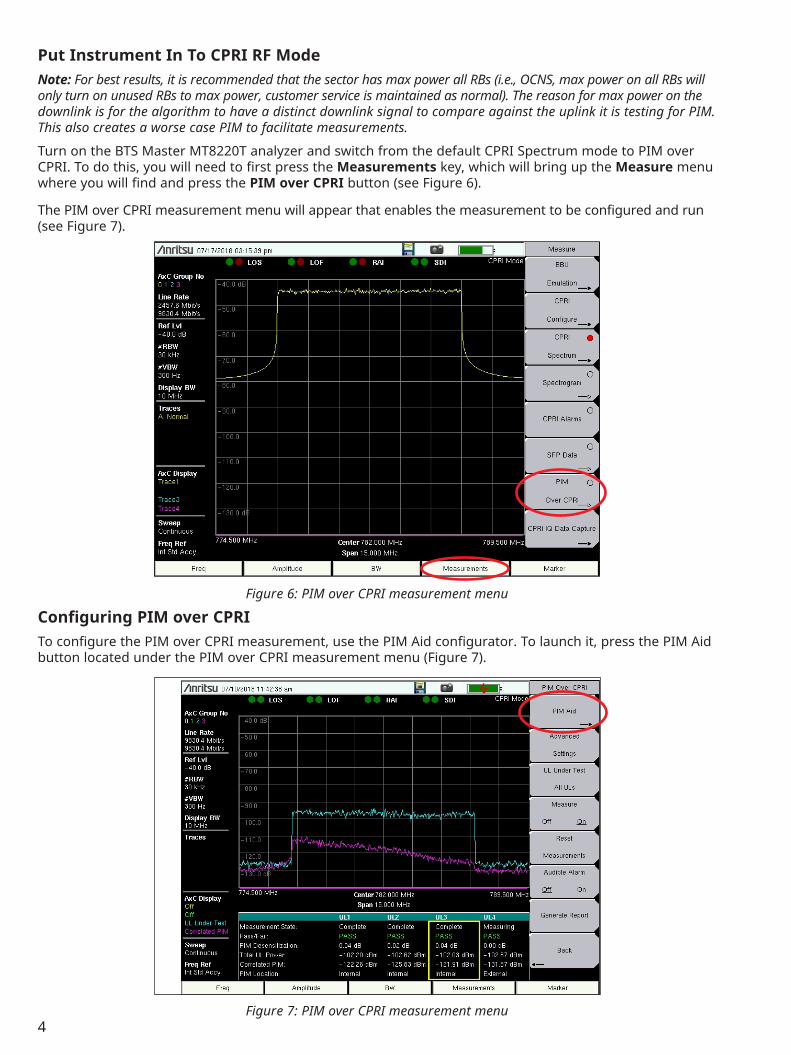
Turn on the BTS Master MT8220T analyzer and switch from the default CPRI Spectrum mode to PIM over CPRI. To do this, you will need to first press the Measurements key, which will bring up the Measure menu where you will find and press the PIM over CPRI button (see Figure 6).
The PIM over CPRI measurement menu will appear that enables the measurement to be configured and run (see Figure 7).
Configuring PIM over CPRITo configure the PIM over CPRI measurement, use the PIM Aid configurator. To launch it, press the PIM Aid button located under the PIM over CPRI measurement menu (Figure 7).
Figure 7: PIM over CPRI measurement menu
Figure 6: PIM over CPRI measurement menu
5
Using PIM Aid: Press PIM Aid button (vertical buttons on right side)
The PIM Aid screen will appear. This is where all PIM over CPRI measurement configurations will be made (Figure 8).
The PIM Aid screen is separated into the following sections:
• Site Configuration Choose the type of system in place: SISO, 2x2 MIMO, 2x4 MIMO This is based on the current system’s site configuration and tells the algorithm how many downlinks to use for the PIM measurement against each uplink signal.
• Pass Fail PIM Desensitization Set desensitization level: Default value is 3 dB PIM desensitization can be thought of as the amount of noise in the uplink signal caused by PIM. Tests in the field show that a PIM desensitization value of 10 dB will typically downgrade the uplink data throughput by 50%. Each operator will need to determine what an acceptable value is for their network. For example, there may be different values for tower-top versus rooftop radios due to the higher potential for PIM in rooftop installations.
• Downlink Configuration The downlink configuration sets up all of the necessary connection and calculation values needed for PIM over CPRI measurements.
• Frequency Input the Downlink Center Frequency: xxx MHz The PIM measurement algorithm needs the center frequency of the LTE downlink under test as one of the values that determine the IM product for the test.
• LTE BW Set the LTE carrier bandwidth under test: 5, 10, 15, 20 MHz The PIM measurement algorithm needs the bandwidth of the LTE downlink under test as another value that determines the IM product for the test.
• DL AxC Configuration Configure the AxC container group for each MIMO carrier: ex: DL 1 AxC = 0 and DL 2 AxC = 1 The DL AxC configuration locates the individual downlink MIMO carrier on the CPRI link needed for the measurement. For most Nokia and Samsung radio configurations, it is recommended to start with AxC 0 and AxC 1 for the two downlinks. This can be adjusted using the View DL configuration if needed.
Figure 8: PIM Aid screen
6
• Line Rate Press button to autodetect the CPRI line rate: ex: 2457.6 Mbit/s = Line Rate 3 By pressing the Line Rate button, it will autodetect the correct line rate of the CPRI link connected. A green light at the top of the screen will appear to show a good CPRI connection.
• Radio Preset Choose the radio manufacturer under test: Alcatel/Nokia, Samsung The radio preset has the default CPRI RF configuration settings needed to connect to Alcatel/Nokia or Samsung RRHs/BBUs.
• View DL Configuration Once all other downlink settings have been configured, press View DL Configuration to review the spectrum traces and verify they are configured correctly. This will show a spectrum view of the downlink LTE MIMO carriers. Downlink carriers are easily identified since the rise and fall of the signal is rounded, whereas uplink carriers have sharp, vertical rises and falls. If you do not see a proper LTE downlink signals, then most likely the AxC Group has been configured incorrectly. The AxC group number can be changed by pressing the appropriate Trace/AxC button (DC1 = Trace1 or DC2 = Trace2) on the right side of the menu and scrolling through the available AxC Groups until the correct signal is found (Figure 9).
Depending on the site configuration (SISO 2x2 or 2x4 MIMO), you will have the appropriate number of Trace/AxC Group buttons available.
• Uplink Configuration Input the Uplink Center Frequency: xxx MHz The algorithm needs the center frequency of the LTE uplink under test as one of the values that determine the IM product for the test. The combination of the downlink to uplink center frequency separation and the LTE carrier bandwidth values will determine the IM product under test.
• LTE BW Choose the LTE Carrier Bandwidth (BW) under test; 5, 10, 15, 20 MHz The PIM measurement algorithm needs the bandwidth of the LTE uplink under test as another value that determines the IM product for the test. If this was a 2nd or 3rd harmonic, the carrier’s bandwidths could be different (e.g., 850 MHz = 10 MHZ BW and 1700 MHz = 20 MHz BW). This helps the algorithm to correctly make both self-generated PIM and harmonic measurements.
Note: The LTE BW of two different carriers used in a harmonic measurement can be different.
Figure 9: View DL configuration
7
• UL AxC Configuration Configure the AxC Container Group for each of the MIMO carriers: ex., UL 1 AxC = 0 & UL 2 AxC = 1 The UL AxC configuration locates the individual uplink MIMO carriers on the CPRI link needed for the measurement. For most Alcatel/Nokia and Samsung filed configurations, it is recommended to start with AxC 0, AxC 1, AxC 2, and AxC 3 for the possible four uplinks. This can be adjusted using the View UL configuration if needed.
• Line Rate Press the Line Rate button to autodetect the CPRI line rate: ex., 2457.6 Mbit/s = Line Rate 3. This will autodetect the correct line rate of the CPRI link connected. A green light at the top of the screen indicates a good CPRI connection.
Note: The line rate of two different carriers used in a harmonic measurement can be different.
• Radio Preset Select the radio manufacturer under test: Alcatel/Nokia or Samsung The radio preset has the default CPRI RF configuration settings needed to connect to Nokia/ALu or Samsung RRHs/BBUs.
Note: Some vendors use different downlink and uplink CPRI configurations. The presets already have those values.
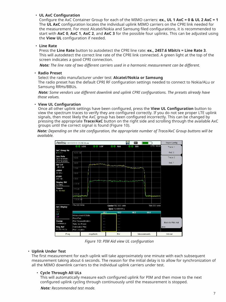
• View UL Configuration Once all other uplink settings have been configured, press the View UL Configuration button to view the spectrum traces to verify they are configured correctly. If you do not see proper LTE uplink signals, then most likely the AxC group has been configured incorrectly. This can be changed by pressing the appropriate Trace/AxC button on the right side and scrolling through the available AxC groups until the correct signal is found (Figure 10).
Note: Depending on the site configuration, the appropriate number of Trace/AxC Group buttons will be available.
• Uplink Under Test The first measurement for each uplink will take approximately one minute with each subsequent measurement taking about 6 seconds. The reason for the initial delay is to allow for synchronization of all the MIMO downlink carriers to the individual uplink carriers under test.
• Cycle Through All ULs This will automatically measure each configured uplink for PIM and then move to the next configured uplink cycling through continuously until the measurement is stopped.
Note: Recommended test mode.
Figure 10: PIM Aid view UL configuration
8
• UL # Allows the measurement of an individual uplink at a time by selecting the individual UL under test: UL 1, UL 2, UL 3, UL 4. This is a manual measurement process, however, useful if only a specific MIMO antenna combination is showing PIM and easy to verify if PIM mitigation has fixed the problem.
• Save and Measure Once everything is configured and verified, press Save and Measure. This brings up the PIM over CPRI measurement screen with all of the configurations saved and will automatically start the measurement.Note: it will take a few seconds before the measurement starts as the instrument configures the settings from the PIM Aid window.
• Exit (Cancel) Exit from the PIM Aid window without saving any changes entered. If you make any changes, the Exit button goes away. Make sure all your setting are correct.
Making PIM Over CPRI MeasurementsOnce Save and Measure has been selected in the PIM Aid window, the BTS Master analyzer will automatically return to the PIM over CPRI screen and start the measurement. There are a few options available on this screen:
• Measure The Measure Off/On button is available when it may be necessary to stop and restart the measurement (Figure 11). Simply press the Measure button on the right to stop the measurement (Off will be underlined). To restart the measurement, press the Measure button again (On will be underlined). If Cycle through ULs is selected, then the measurement will cycle through all the available uplinks.
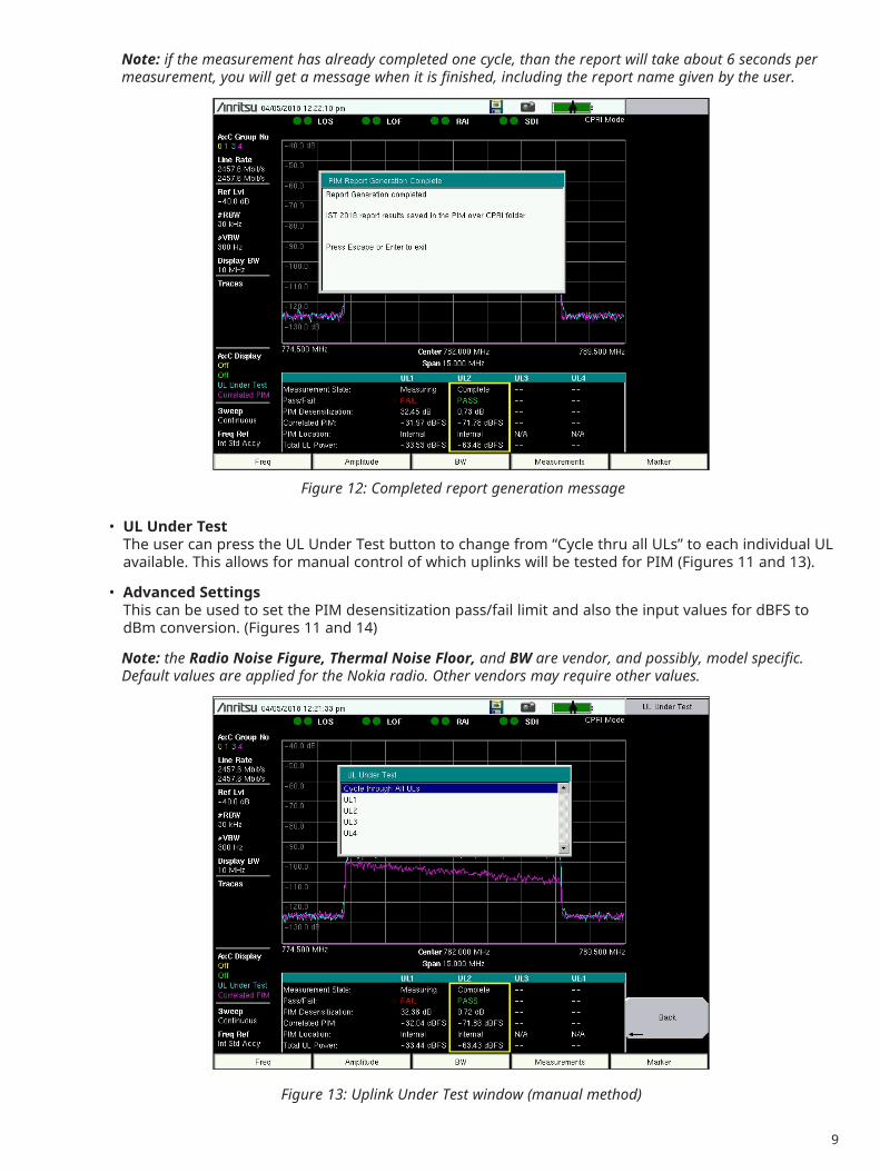
• Generate Report Once the measurement has been completed, this feature will automatically cycle through all ULs tested, gather all the JPGs and measurement files generated for each UL under test, and create a report that is saved in the PIM over CPRI folder within the instrument internal file system. A confirmation screen will appear in the window when the report has been completed (Figures 11 and 12).
Figure 11: Measure On/Off
9
Note: if the measurement has already completed one cycle, than the report will take about 6 seconds per measurement, you will get a message when it is finished, including the report name given by the user.
• UL Under Test The user can press the UL Under Test button to change from “Cycle thru all ULs” to each individual UL available. This allows for manual control of which uplinks will be tested for PIM (Figures 11 and 13).
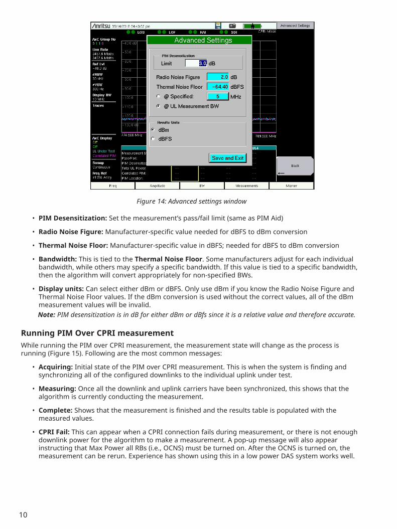
• Advanced Settings This can be used to set the PIM desensitization pass/fail limit and also the input values for dBFS to dBm conversion. (Figures 11 and 14)
Note: the Radio Noise Figure, Thermal Noise Floor, and BW are vendor, and possibly, model specific. Default values are applied for the Nokia radio. Other vendors may require other values.
Figure 12: Completed report generation message
Figure 13: Uplink Under Test window (manual method)
10
• PIM Desensitization: Set the measurement’s pass/fail limit (same as PIM Aid)
• Radio Noise Figure: Manufacturer-specific value needed for dBFS to dBm conversion
• Thermal Noise Floor: Manufacturer-specific value in dBFS; needed for dBFS to dBm conversion
• Bandwidth: This is tied to the Thermal Noise Floor. Some manufacturers adjust for each individual bandwidth, while others may specify a specific bandwidth. If this value is tied to a specific bandwidth, then the algorithm will convert appropriately for non-specified BWs.
• Display units: Can select either dBm or dBFS. Only use dBm if you know the Radio Noise Figure and Thermal Noise Floor values. If the dBm conversion is used without the correct values, all of the dBm measurement values will be invalid.Note: PIM desensitization is in dB for either dBm or dBfs since it is a relative value and therefore accurate.
Running PIM Over CPRI measurementWhile running the PIM over CPRI measurement, the measurement state will change as the process is running (Figure 15). Following are the most common messages:
• Acquiring: Initial state of the PIM over CPRI measurement. This is when the system is finding and synchronizing all of the configured downlinks to the individual uplink under test.
• Measuring: Once all the downlink and uplink carriers have been synchronized, this shows that the algorithm is currently conducting the measurement.
• Complete: Shows that the measurement is finished and the results table is populated with the measured values.
• CPRI Fail: This can appear when a CPRI connection fails during measurement, or there is not enough downlink power for the algorithm to make a measurement. A pop-up message will also appear instructing that Max Power all RBs (i.e., OCNS) must be turned on. After the OCNS is turned on, the measurement can be rerun. Experience has shown using this in a low power DAS system works well.
Figure 14: Advanced settings window
11
PIM Over CPRI Results• Pass/Fail: Based on the PIM desensitization limit set in either the PIM Aid window (Figure 8) or
Advanced Settings window (Figure 14). Field tests show that a 10 dB PIM desensitization level can reduce data throughput by up to 50%. (Figure 15)
• PIM Desensitization: This is the relative ratio of PIM within an uplink signal (given in dB) calculated by using the correlated PIM value and the total uplink power (Figure 15).
• Total Uplink Power: The total RF power of the uplink carrier displayed in the table and shown as the light blue trace in the spectrum view (Figure 15).
• Correlated PIM: The value displayed is the total correlated PIM power found within the uplink signal, based on comparing all the available downlink signals compared to the uplink signal under test. The PIM is given as a dBFS or dBm value (Absolute value) and also displayed as the purple trace in the spectrum view (Figure 15), this shows PIM distributed across the uplink carrier.
• PIM Location: The PIM over CPRI algorithm can determine if the measured PIM is within the antenna system or external to the antenna in a MIMO system (Figure 15). Note: PIM over CPRI configurations can be saved for reuse, and distributed to other team members.
Figure 15: PIM over CPRI results table and graph
12
Actions After MeasurementIf PIM is found outside of the pass/fail established limits, it is important to determine if the PIM is internal or external to the antenna system. If it is within the antenna system, than traditionally a tower crew is called in to troubleshoot the issue with an RF-based PIM tester. This will require them to remove the RF connections between the RRH and antenna in order to find which component within the antenna system is faulty. Once the issues have been resolved, the system can be retested to validate the fixes. Note: Since each MIMO uplink is measured individually and normally starts from antenna 0 to antenna 3, the PIM over CPRI result will guide the user to the RF cable that is causing PIM.
If PIM is found external to the antenna system (e.g., a rooftop), then a team can be called in to search for the external component(s) causing it in the system. This can be accomplished with a fast-scanning spectrum analyzer and antenna specifically designed to detect PIM (e.g., Anritsu’s PIM Hunter™ antenna). The team would simply slowly walk the area with this solution and look for RF signal spikes in the spectrum analyzer. Once the issues are found, there are numerous products that can be used to absorb or deflect RF signals in order to reduce PIM back into the antenna system.
Once all major contributors to PIM are detected and fixed then it is time to retest to validate the PIM mitigation fixes.
Conclusion PIM over CPRI is a new way to measure and detect PIM over the CPRI link. It uses live traffic (with OCNS on) to find PIM problems in a radio and can be used at any time of the day. This new patented PIM over CPRI measurement option will not only measure PIM, it will also detect if PIM is internal or external to the antenna in a MIMO system. This will greatly reduce OpEx costs of tearing apart good antenna system installations when, in reality, it may not be needed since the problem is external.
The PIM over CPRI option for the BTS Master MT8220T complements existing Anritsu RF PIM instruments (including PIM Master™ MW82119B, PIM Hunter™, and spectrum analyzer) by being the first line of defense, since this test is minimally intrusive (install optical tap) and can be done at ground level. PIM over CPRI is the first step in determining if a tower crew needs to be called in to fix PIM problems at the top of a tower or roof.
® Anritsu All trademarks are registered trademarks of their respective companies. Data subject to change without notice. For the most recent specifications visit: www.anritsu.com
• United States Anritsu Company450 Century Parkway, Suite 190, Allen, TX 75013 U.S.A. Toll Free: +1-800-267-4878 Phone: +1-972-644-1777
• Brazil Anritsu Electrônica Ltda.Praça Amadeu Amaral, 27 - 1 Andar 01327-010 - Bela Vista - Sao Paulo - SP - Brazil Phone: +55-11-3283-2511 Fax: +55-11-3288-6940
• Mexico Anritsu Company, S.A. de C.V.Blvd Miguel de Cervantes Saavedra #169 Piso 1, Col. Granada Mexico, Ciudad de Mexico, 11520, MEXICO Phone: +52-55-4169-7104
• Russia Anritsu EMEA Ltd. Representation Office in RussiaTverskaya str. 16/2, bld. 1, 7th floor. Moscow, 125009, Russia Phone: +7-495-363-1694 Fax: +7-495-935-8962
• Spain Anritsu EMEA Ltd. Representation Office in SpainEdificio Cuzco IV, Po. de la Castellana, 141, Pta. 5 28046, Madrid, Spain Phone: +34-915-726-761 Fax: +34-915-726-621
• United Arab Emirates Anritsu EMEA Ltd. Dubai Liaison OfficeP O Box 500413 - Dubai Internet City Al Thuraya Building, Tower 1, Suite 701, 7th floor Dubai, United Arab Emirates Phone: +971-4-3670352 Fax: +971-4-3688460
• India Anritsu India Pvt Ltd.6th Floor, Indiqube ETA, No.38/4, Adjacent to EMC2, Doddanekundi, Outer Ring Road, Bengaluru – 560048, India Phone: +91-80-4058-1300 Fax: +91-80-4058-1301
• P. R. China (Shanghai) Anritsu (China) Co., Ltd.27th Floor, Tower A, New Caohejing International Business Center No. 391 Gui Ping Road Shanghai, Xu Hui Di District, Shanghai 200233, P.R. China Phone: +86-21-6237-0898 Fax: +86-21-6237-0899
• P. R. China (Hong Kong) Anritsu Company Ltd.Unit 1006-7, 10/F., Greenfield Tower, Concordia Plaza, No. 1 Science Museum Road, Tsim Sha Tsui East, Kowloon, Hong Kong, P. R. China Phone: +852-2301-4980 Fax: +852-2301-3545
• Japan Anritsu Corporation8-5, Tamura-cho, Atsugi-shi, Kanagawa, 243-0016 Japan Phone: +81-46-296-6509 Fax: +81-46-225-8352
• Korea Anritsu Corporation, Ltd.5FL, 235 Pangyoyeok-ro, Bundang-gu, Seongnam-si, Gyeonggi-do, 13494 Korea Phone: +82-31-696-7750 Fax: +82-31-696-7751
• Australia Anritsu Pty Ltd.Unit 20, 21-35 Ricketts Road, Mount Waverley, Victoria 3149, Australia Phone: +61-3-9558-8177 Fax: +61-3-9558-8255
• Taiwan Anritsu Company Inc.7F, No. 316, Sec. 1, Neihu Rd., Taipei 114, Taiwan Phone: +886-2-8751-1816 Fax: +886-2-8751-1817
Specifications are subject to change without notice.