Precision Regulator – Series IR1000/2000/3000 1025 Air Preparation For more product options and details see our specific catalogues or on-line information. Model Max. supply pressure Min. supply pressure Regulating pressure range Input signal pressure Sensitivity Repeatability Linearity Air consumption Port size Pressure gauge port Ambient and fluid temperature Weight [kg] (2) (1) (3) (4) IR100 IR1000: 0.005 to 0.2 MPa IR1010: 0.01 to 0.4 MPa IR1020: 0.01 to 0.8 MPa 1/8 0.14 IR200 IR2000: 0.005 to 0.2 MPa IR2010: 0.01 to 0.4 MPa IR2020: 0.01 to 0.8 MPa 1/4 0.30 IR300 Set pressure + 0.1 MPa IR3000: 0.01 to 0.2 MPa IR3010: 0.01 to 0.4 MPa IR3020: 0.01 to 0.8 MPa 11.5 l /min (ANR) or less 4.4 l /min (ANR) or less 4.4 l /min (ANR) or less 4.4 l /min (ANR) or less 1/4, 3/8, 1/2 1/8 (2 locations) 0.64 IR2120 Set pressure + 0.05 MPa 0.01 to 0.8 MPa 1/4 0.35 0.01 to 0.8 MPa IR3120 Set pressure + 0.1 MPa 0.01 to 0.8 MPa 11.5 l /min (ANR) or less 1/4, 3/8, 1/2 0.71 0.01 to 0.8 MPa Basic type Air operated type 1.0 MPa Set pressure + 0.05 MPa Within 0.2% of full span Within ±0.5% of full span Within ±1% of full span –5 to 60ºC (No freezing) — — Note 1) With the condition of no flow on the output side. Together with the set pressure, be sure to maintain a minimum differential pressure of 0.05 MPa for models IR1000 and IR2000, and 0.1 MPa for model IR3000. Note 2) Applicable only to air operated types IR2120 and IR3120. Note 3) Indicates the linearity of the output pressure with respect to the input signal pressure. Note 4) Air is normally being discharged to the atmosphere from a bleed hole or an exhaust port. IR1000 IR2000 IR3000 For series IR1000/2000 IR1000 IR2000 IR3000 Application Precision regulator Body size IR 2 Regulating pressure range 00 02 1 2 3 0.005 to 0.2 MPa 0.01 to 0.4 MPa 0.01 to 0.8 MPa Note) Air operated type is model IR2120 only. Note) Air operated type is model IR3120 only. 0 1 2 For series IR3000 0.01 to 0.2 MPa 0.01 to 0.4 MPa 0.01 to 0.8 MPa 0 1 2 Port size Symbol 01 02 03 04 size 1/8 1/4 3/8 1/2 Basic type Air operated type 0 Handle type Air pilot (Note) Adjustment type 0 1 Note) The IR*1*0 type (Air operated) is only available for body sizes 2 and 3. Note) The IR*1*0 type (Air operated) is only available for body sizes 2 and 3. Precision Regulator Series IR1000/2000/3000 • Precise air pressure regulator for instrument applications. • Three body sizes available. • Pressure unaffected by supply pressure or demand changes. • Bracket and pressure gauge can be mounted from 2 directions. • Compact and lightweight. • Superior relief flow characteristics. Features IR1000-F01 IR1010-F01 IR1020-F01 Product Recommendation Stocked items for fast delivery (Accessories) Series G - Pressure Gauges - www.smc.eu (Related Products) Series AR - Air Regulators - page 1084 Series ITV - Electro-pneumatic Regulators - page 1104 Series ISE - Digital Pressure Switches - page 1273 Series AC - Air Preparation Modular Units - page 1076 Series AC-A - Air Preparation Modular Units - page 1076 Accessories and Related Products How to Order IR2000-F02 IR2010-F02 IR2020-F02 IR2120-F02 IR3000-F02 IR3000-F03 IR3000-F04 IR3010-F02 IR3010-F03 Symbol Specifications IR3010-F04 IR3020-F02 IR3020-F03 IR3020-F04 IR3120-F03 IR3120-F04 F G Thread type F (At supply pressure of 1.0 MPa)
Transcript
Precision Regulator – Series IR1000/2000/3000 1025
Air
Pre
par
atio
n
For more product options and details see our specifi c catalogues or on-line information.
Model
Max. supply pressure
Min. supply pressure
Regulating pressure range
Input signal pressureSensitivityRepeatabilityLinearity
Air consumption
Port sizePressure gauge portAmbient and fluid temperatureWeight [kg]
(2)
(1)
(3)
(4)
IR100
IR1000: 0.005 to 0.2 MPaIR1010: 0.01 to 0.4 MPaIR1020: 0.01 to 0.8 MPa
1/8
0.14
IR200
IR2000: 0.005 to 0.2 MPaIR2010: 0.01 to 0.4 MPaIR2020: 0.01 to 0.8 MPa
1/4
0.30
IR300
Set pressure + 0.1 MPa
IR3000: 0.01 to 0.2 MPaIR3010: 0.01 to 0.4 MPaIR3020: 0.01 to 0.8 MPa
11.5 l /min (ANR) or less4.4 l /min (ANR) or less 4.4 l /min (ANR) or less 4.4 l /min (ANR) or less
1/4, 3/8, 1/2 1/8 (2 locations)
0.64
IR2120
Set pressure + 0.05 MPa
0.01 to 0.8 MPa
1/4
0.35
0.01 to 0.8 MPa
IR3120
Set pressure + 0.1 MPa
0.01 to 0.8 MPa
11.5 l /min (ANR) or less
1/4, 3/8, 1/2
0.71
0.01 to 0.8 MPa
Basic type Air operated type
1.0 MPa
Set pressure + 0.05 MPa
Within 0.2% of full spanWithin ±0.5% of full span
Within ±1% of full span
–5 to 60ºC (No freezing)
—
—
Note 1) With the condition of no flow on the output side. Together with the set pressure, be sure to maintain a minimum differential pressure of 0.05 MPa for models IR1000 and IR2000, and 0.1 MPa for model IR3000.Note 2) Applicable only to air operated types IR2120 and IR3120. Note 3) Indicates the linearity of the output pressure with respect to the input signal pressure.Note 4) Air is normally being discharged to the atmosphere from a bleed hole or an exhaust port.
IR1000IR2000IR3000 For series IR1000/2000
IR1000
IR2000
IR3000
ApplicationPrecision regulator
Body size
IR 2
Regulating pressure range
0 0 02
123
0.005 to 0.2 MPa 0.01 to 0.4 MPa0.01 to 0.8 MPa
Note) Air operated type is model IR2120 only.
Note) Air operated type is model IR3120 only.
012
For series IR30000.01 to 0.2 MPa0.01 to 0.4 MPa0.01 to 0.8 MPa
012
Port size
Symbol
01020304
size
1/81/43/81/2
Basic type
Air operated type
0
Handle typeAir pilot (Note)
Adjustment type01
Note) The IR*1*0 type(Air operated) is only availablefor body sizes 2 and 3.
Note) The IR*1*0 type (Air operated)is only available for body sizes 2 and 3.
Precision RegulatorSeries IR1000/2000/3000
• Precise air pressure regulator for instrument applications.• Three body sizes available.• Pressure unaffected by supply pressure or demand changes.• Bracket and pressure gauge can be mounted from 2 directions.• Compact and lightweight.• Superior relief flow characteristics.
Features
IR1000-F01IR1010-F01IR1020-F01
Product Recommendation
Stocked items for fast delivery (Accessories)Series G - Pressure Gauges - www.smc.eu(Related Products)Series AR - Air Regulators - page 1084Series ITV - Electro-pneumatic Regulators - page 1104Series ISE - Digital Pressure Switches - page 1273Series AC - Air Preparation Modular Units - page 1076Series AC-A - Air Preparation Modular Units - page 1076
Accessories and Related Products
How to Order
IR2000-F02IR2010-F02IR2020-F02
IR2120-F02IR3000-F02IR3000-F03
IR3000-F04IR3010-F02IR3010-F03
Symbol
Specifications
IR3010-F04IR3020-F02IR3020-F03
IR3020-F04IR3120-F03IR3120-F04
F
GThread type
F
(At supply pressureof 1.0 MPa)
Series IR1000/2000/3000 – Precision Regulator1026
Air
Prep
aration
DescriptionIR1000
G33-2-01
IR1010P36201023G33-4-01
IR1020
G33-10-01
IR2000
G43-2-01
IR2010P36202028G43-4-01
IR2020/2120
G43-10-01
IR3010P362030-20
G43-4-01
IR3020/3120
G43-10-01
IR3000
G43-2-01
Part no.
∗ Accuracy 3% (Full span)
BracketPressure gauge ∗
IR1000KT-IR1000
IR2000KT-IR2000
IR3000KT-IR3000
Applicable modelSpares kit
IR1000-01 IR2000-02
IR3000-0
ø30
44 51 ≅90
1010
Panel mounting hole
ø12.5
Panel
50 50
Exhaust
≅60
OUT(2)SUP(1)
Bleed
M6 x P0.5 5.5
ø9.5
Max
. 4
63
ø43
7111
18≅1
23
4.5
Bleed
SUP(1) OUT(2)
≅43
M5X0.5
35 EXH35
2- 1/8Pressure gauge port
2.3
48
≅6866
EXH(3)
ø43
76≅1
4822
M6 x P0.5Mounting hole
Bracket(Option)
Pressure gauge(Option)
8260
2- 1/4 to 1/2Port size
1/2Exhaust port
2- 1/8Port size
2- 1/4Port size 1/8
Pressure gauge port
ø8.5
Panel mounting hole
ø12.5
Panel
Max
. 4
42
252
Mounting hole
Bracket(Option)
Pressure gauge(Option)
28
Max
. 4
Panel mounting hole
Panel
ø10.5
50 Mounting hole
Bracket(Option)
Pressure gauge(Option)
302 36
ø15.5
Bleed
SUP(1)
66
OUT(2)
9
2- 1/8Pressure gauge port
234
Accessory (Option)/Part No.
Spares Kits
Dimensions
Compact Electro-Pneumatic Regulator – Series ITV0000/0090 1027
Air
Pre
par
atio
n
For more product options and details see our specifi c catalogues or on-line information.
• Realizes space-savings and reduction of weight.• Built-in one touch fitting.• Error indication LED display.• Equivalent to IP65.• High speed response time 0.1 sec.• High stability.• Can be manifold mounted.• Vacuum variant available.
Features
ITV0010-0NITV0010-0MNITV0010-3MNITV0010-3N
Product Recommendation
Stocked items for fast delivery
Series AC - Air Preparation - page 1076Series PF2A - Digital Flow Switch for Air - page 1309Series ZSE/ISE0A - Digital Pressure Switch for Air - page 1273Series KQ2 - Fittings - page 1184Series TU - Tubing - page 1223
Related Products
For single unit and single unit for manifold
ITV00 1 0 3 N
—M
Base typeFor single unitFor manifolds
1359
Pressure range0.1 MPa0.5 MPa0.9 MPa–100 kPa
0123
Input signalCurrent type 4 to 20 mA DC (Sink type)Current type 0 to 20 mA DC (Sink type)
Voltage type 0 to 5 VDCVoltage type 0 to 10 VDC
01
Power supply voltage24 VDC
12 to 15 VDC
IITV00 020203
10
Stations2 stations3 stations
10 stations
··· ···
Note) A DIN rail with the length specified by the number of stations is attached to the manifold. For dimensions of the DIN rail, refer to the external dimensions.
NSL
Without cable connector3m length with straight connector.2m length with right angle connector.
Cable Assembly
How to Order ITV0000
How to Order ITV0000/0090 Manifold
ITV0030-0NITV0030-0MNITV0030-2NITV0030-3MN
ITV0030-3NITV0050-0MNITV0050-0NITV0050-3MN
ITV0050-3NITV0090-3NIITV00-02IITV00-04
RoHS
Series ITV0000/0090 – Compact Electro-Pneumatic Regulator1028
Within ±0.12% (Full span)/ºC0 to 50ºC (With no condensation)
IP65 equivalent ∗Built-in One-touch fittings
100 g or less (without options)
ITV001
0.2 MPa0.001 to 0.1 MPa
ITV003Set pressure +0.1 MPa
0.001 to 0.5 MPa
ITV005
0.001 to 0.9 MPa
For single unit Metric sizeMetric size
ITV009Set pressure –1 kPa
–101 kPa–1 to –100 kPa
1.0 MPa
Power supply voltage 24 VDC type: 0.12 A or lessPower supply voltage 12 to 15 VDC type: 0.18 A or less
1 to 5 VDC (Output impedance: approximately 1 kΩ) Output accuracy: Within ±6% (Full span)
z, x, c: ø4z, c: ø6, x: ø4
(1)
Note 1) Indicates the weight of a single unit. For IITV00-n Total weight [g] Stations (n) x 100 + 130 (Weight of end block A, B assembly) + Weight [g] of DIN rail
Note 2) Specifications other than the following are optional. Pressure range: 0.1 MPa, 0.5 MPa, 0.9 MPa, Power supply voltage: 24 VDC, Input signal: 0 to 10 VDC
Note 3) When there is a downstream flow consumption, pressure may become unstable depending on piping conditions.
∗ When using under the conditions equivalent to
IP65, connect the fitting or tube to the breathing hole prior to use.
Manifold
Standard Specifications
Option
Compact Electro-Pneumatic Regulator – Series ITV0000/0090 1029
Air
Pre
par
atio
n
For more product options and details see our specifi c catalogues or on-line information.
Fluiid Characteristics
Linearity, Hyteresis
0 25 50 75–1
–0.6
–0.8
–0.4
–0.2
0.6
0.4
0.2
0
0.81
100
Out
put d
evia
tion
fact
or (%
F.S
.)
Input signal (%F.S.)
Repeatability
1 2 3 4–1
–0.5
0.5
0
1
5
Out
put d
evia
tion
fact
or (%
F.S
.)
Count
Pressure Characteristics
0.15 0.16 0.17 0.18 0.19–1
–0.5
0.5
0
1
0.20
Out
put d
evia
tion
fact
or (%
F.S
.)
Supply pressure [MPa]
Flow Characteristics
0 1 1.50.5 2 2.5 3 3.50
20
40
100
80
60
120
4
Set p
ress
ure
[kPa
]
Flow rate [l/min (ANR)]
20 kPa
40 kPa
60 kPa
80 kPa
100 kPa
10 kPa
With 50% of signal input
Supply pressure: 0.2 MPaSet pressure: 0.05 MPa
With 50% of signal input
Supply pressure: 0.6 MPaSet pressure: 0.25 MPa
Linearity, Hyteresis
0 25 50 75–1
–0.6
–0.8
–0.4
–0.2
0.6
0.4
0.2
0
0.81
100
Out
put d
evia
tion
fact
or (%
F.S
.)
Input signal (%F.S.)
Repeatability
1 2 3 4–1
–0.5
0.5
0
1
5
Out
put d
evia
tion
fact
or (%
F.S
.)
Count
Pressure Characteristics
0.2 0.3 0.4 0.5 0.6 0.7 0.8 0.9–1
–0.5
0.5
0
1
1.0
Out
put d
evia
tion
fact
or (%
F.S
.)
Supply pressure [MPa]
Flow Characteristics
0 21 3 4 5 60
100
200
500
400
300
600
7
Set p
ress
ure
[kPa
]
Flow rate [l/min (ANR)]
100 kPa
200 kPa
300 kPa
400 kPa
500 kPa
50 kPa
Series ITV001
Series ITV003
Out
Return
Out
Return
Out
Return
Out
Return
Series ITV0000/0090 – Compact Electro-Pneumatic Regulator1030
Air
Prep
aration
Flow Characteristics
Linearity, Hyteresis
0 25 50 75–1
–0.6
–0.8
–0.4
–0.2
0.6
0.4
0.2
0
0.81
100
Out
put d
evia
tion
fact
or (%
F.S
.)
Input signal (%F.S.)
Repeatability
1 2 3 4–1
–0.5
0.5
0
1
5
Out
put d
evia
tion
fact
or (%
F.S
.)
Count
With 50% of signal input
Supply pressure: 1.0 MPaPressure Characteristics
0.4 0.6 0.8 1.0–1
–0.5
0.5
0
1
1.2
Out
put d
evia
tion
fact
or (%
F.S
.)
Supply pressure [MPa]
Flow Characteristics
0 1 2 3 4 5 60
200
300
100
400
900
800
500
600
700
1000
7
Set p
ress
ure
[kPa
]
Flow rate [l/min (ANR)]
100 kPa
200 kPa
300 kPa
800 kPa
900 kPa
700 kPa
600 kPa
500 kPa
400 kPa
50 kPa
Set pressure: 0.45 MPa
Series ITV005
Out
Return
Out
Return
Series ITV009With 50% of signal inputLinearity, hysteresis
0 25 50 75-1
-0.5
0.5
0
1
100
Out
put d
evia
tion
fact
or %
F.S
.
Input signal % F.S.
Repeatability
1 2 3 4-1
-0.5
0.5
0
1
5
Out
put d
evia
tion
fact
or %
F.S
.
Repetition
Pressure characteristics
-120 -100 -80 -60 -40-1
-0.5
0.5
0
1
-20
Out
put d
evia
tion
fact
or %
F.S
.
Supply pressure MPa
Flow characteristics
0 1 1.50.5 2 2.5 3 3.5-120
-100
-80
-20
-40
-60
0
4
Set p
ress
ure
kPa
Flow rate l/min (ANR)
Out
Return
Out
Return
–100kPa
–10kPa–20kPa
–40kPa
–60kPa
–80kPa
Compact Electro-Pneumatic Regulator – Series ITV0000/0090 1031
Air
Pre
par
atio
n
For more product options and details see our specifi c catalogues or on-line information.
Note) When useing under the conditions equivalent to IP65, connect the fitting or tube to the bleed hole prior to use.
Flat bracket(Option) L-bracket
(Option)
Dimensions For Single Unit
ø9.721.8
24.6
2000
50
ø4
M8
x 1
BodyCable connector (4-wire)Right angle type (Option) Minimium bending radius 80
Series ITV0000/0090 – Compact Electro-Pneumatic Regulator1032
Air
Prep
aration
M8 x 1Cable connection thread
Bushing assembly
OUTx
Breathing hole (M3)
OUT port(ø4)
5 8
1515
18.526.5
2.7
84 86
3.7
5056
9
2
Note)
PWR
ERR
Note) When using under the conditions equivalent to IP65, connect a fitting or tube to the bleed hole prior to use.
Dimensions for Single Unit for Manifold
Note) For dimensions of the cable connector, refer to single unit .
PWR
ERR
PWR
ERR
SUP, VACzport
EXH, ATMcport
OUTxport(ø4)
(ø)
(ø6)
1
3
1
3
2 2 2
Breathing hole (M3)
D side U side1 2 ····stations
50
L2
40
11 11
402020
L19.59.5
950
3 (8)Dimensions in inch arenoted in parentheses.
3.7
56
2540
82
2540
6.56.5
5
89.5
5
25
PWR
ERR
PWR
ERR
No.
ITV00
ITV009
EXHSUP
ATMVAC
OUT
Port Locationz x c
135
[mm]Manifold stations n
L1L2
260
110.5
3 75123
4 90148
5105
160.5
6120173
7135
185.5
8150198
9165223
10180
235.5
Note)
4-M3 thread depth 3Mounting hole
Note) When using under the conditions equivalent to IP65, connect the fittings or tubing to the bleed hole prior to use.
Note) Stations are counted starting from the D side.
Dimensions for Manifold
Compact Electro-Pneumatic Regulator – Series ITV0000/0090 1033
Air
Pre
par
atio
n
For more product options and details see our specifi c catalogues or on-line information.
Connect the cable to the connector on the body with the wiring arranged as shown below. Proceed carefully, as incorrect wiring can cause damage.Further, use DC power with sufficient capacity and a low ripple.
A right angle type cable is also available. The entry direction for the right angle type connector is to downwards (SUP port side). Never turn the connector as it is not designed to turn. Using force to turn the connector will damage the connector coupling.
3: (Blue)1: (Brown)
2: (White) 4: (Black)
Wiring DiagramsCurrent signal type
Analogue output, voltage type
Vs
A
Voltage signal type
Monitor output voltage
Vs
Vin
Vs: Power Supply 24 VDC ±10% 12 to 15 VDCA : Input signals 4 to 20 mA DC 0 to 20 mA DC
Vs : Power Supply 24 VDC ±10% 12 to 15 VDCVin: Input signals 0 to 5 VDC 0 to 10 VDC
1BrownPower
2WhiteSignal
3BlueCOM
4BlackMonitor
Terminal No.Lead wire colourWiring
Monitor output wiring diagram
Body
Note)
BrownBlue
WhiteBlack
Note)
BrownBlueWhite
Black
BrownBlueWhite
Black
Brown
Blue
White
Black
Precautions
Series ITV1000/2000/3000 – Electro-Pneumatic Regulator1034
• Compact and Lightweight.• Low power consumotion, less than 4W.• Low sensitivity, less than 0.2% (F.S.)• Equivalent to IP65.• Linearity: Within ±1% (F.S.)• Low hysteresis, less than ±0.5% (F.S.)• Fieldbus protocol compatibility: - CC-Link - DeviceNet - Profibus
Series AC - Air Preparation - page 1072Series PF2A - Digital Flow Switch for Air- page 1309 Series ZSE/ISE0A - Digital Pressure Switch for Air - page 1273Series KQ2 - Fittings - page 1184Series TU - Tubing - page 1223
Within ±1% (Full span) Within 0.5% (Full span) Within ±0.5% (Full span) Within 0.2% (Full span)
Within ±0.12% (Full span)/ºC±2%F.S. ±1 digit or less
MPa: 0.001, kgf/cm2: 0.01, bar: 0.01, psi: 0.1 Note 5) , kPa: 10 to 50ºC (No condensation)
IP65Approx. 250 g (without options)Approx. 350 g (without options)Approx. 645 g (without options)
NPN open collector output: Max. 30 V, 80 mAPNP open collector output: Max. 80 mA
Power supply voltage 24 VDC type: 0.12 A or lessPower supply voltage 12 to 15 VDC type: 0.18 A or less
ITV105ITV205ITV305
ITV103ITV203ITV303
ITV101ITV201ITV301
1 to 5 VDC (Output impedance: Approximately 1 kΩ) 4 to 20 mA DC (Sink type) (Load impedance: 250 Ω or less)
Output accuracy within ±6% (Full span)
Figure 1. Input/output characteristics chartInput signal (%F.S.)
00 100
Out
put p
ress
ure
[MPa
]
This range is outside of the control (output). 0.005MPa
Note 1) Please refer to Figure 1 for the relationship between set pressure and input. Because the maximum set pressure differs for each pressure display.
Note 2) 2-wire type 4 to 20 mA DC is not available. Power supply voltage (24 VDC or 12 to 15 VDC) is required.Note 3) Select either analogue output or switch output.
Further, when switch output is selected, select either NPN output or PNP output. When measuring ITV analogue output from 1 to 5VDC, if the load impedance is less than 100 kΩ, the analogue output monitor accuracy of within ±6% (full span) may not be available. The product with the accuracy of within ±6% is supplied upon your request. Output pressure remains unaffected.
Note 4) Adjustment of numerical values such as the zero/span adjustment or preset input type is set based on the minimum units for output pressure display (e.g. 0.01 to 0.50 MPa). Note that the unit cannot be changed.
Note 5) The minimum unit for 0.9 MPa (130 psi) types is 1 psi.Note 6) Value for the state with no over current circuit included. If an allowance is provided for an over current circuit,
the input impedance varies depending on the input current. This is 350Ω or less for an input current of 20 mA DC.Note 7) The above characteristics are confined to the static state. When air is consumed on the output side, the
pressure may fluctuate.Note 8) For communication models, the maximum current consumption is 0.16 A or less.Note 9) For communication models, add roughly 80 g to the weight (100 g for the PROFIBUS DP).Note 10) The ITV1000 series is a Grease-free specification (Wetted parts).
Note 10) Note 10) Note 10)
Current type Note 2)
Voltage typePreset inputCurrent typeVoltage type
Preset input
Switchoutput
AnalogueoutputOutput signal
(monitor output)
Note 3)
ProtocolVersion Note 1)
Configulation file Note 2)
I/O occupation area (input/output data)Communication data resolution
Fail safe
Terminating resistor
Communication speed
Model ITV00-CCCC-LinkVer 1.10
—
12 bit (4096 resolution)
ITV00-DNDeviceNet™Release2.0
EDS
16 bit/16 bit
12 bit (4096 resolution)
— —
ITV00-PRPROFIBUS DP
DP-V0
GSD
16 bit/16 bit
12 bit (4096 resolution)
CLEAR
ITV00-RCRS-232C
—
9.6 kbps
—
—
10 bit (1024 resolution)
HOLD
Note 1) Note that version information is subject to change.Note 2) Configulation files can be downloaded from the SMC's website: http://www.smcworld.comNote 3) The output HOLD value when a CC-Link communications error occurs can be set based on the bit area data.Note 4) The insulation between the electrical signal of the communication system and ITV power supply.
156 k/625 k2.5 M/5 M/10 M bps 125 k/250 k/500 k bps
9.6 k/19.2 k/45.45 k93.75 k/187.5 k/500 k
1.5 M/3 M/6 M/12 M bps
Built into the product(Switch setting)
HOLD/CLEAR(Switch setting)
4 word/4 word, 32 bit/32 bit(per station, remote device station)
HOLD Note 3)/CLEAR(Switch setting)
Electric insulation Note 4) No No Yes No
Rated pressure
Series ITV1000/2000/3000 – Electro-Pneumatic Regulator1036
Air
Prep
aration
Combinations∗ ITV10 models are not applicable.
∗ ITV10 models arenot applicable.
Specifications
135
F02F03F04
Sym
bol Applicable model
ITV20 ITV30
ITV10 ITV20 ITV30
L-bracket assembly (including mounting screws)
Straight type 3 m
Right angle type 3 m
Power cable connector
Description
KT-ITV-F2
P398020-500-3(P398020-504-3 for DeviceNet™)
P398020-501-3(P398020-505-3 for DeviceNet™)
EX9-ACY00-MJ
Part No.
qAir filterwMist separatoreL-bracketrSpacertSpacer with L-bracket (e + r)ySpacer with T-bracket
ITV20
AF30AFM30B310L
Y30Y30L
—
ITV30
AF40AFM40B410L
Y40Y40LY40T
Applicable products and accessoriesApplicable model
Flat bracket L-bracket
1.6
12
2060
40
8440
2236
52
100
22
4 x ø5.58 x ø4.5
4 x ø7
2.3
405
22
40
367
36
7022
14
50
4 x ø5.58 x ø4.5
(8.5)
7
4 x R3.5
15
33
10
50
25
KT-ITV-F1KT-ITV-L2KT-ITV-L1
Flat bracket assembly (including mounting screws)
Bus adapter (CC-Link model only)
Acces-sories
Stan
dard
spec
ifica
tions
Set pressure max. 0.1 MPaSet pressure max. 0.5 MPaSet pressure max. 0.9 MPaConnection G 1/4Connection G 3/8Connection G 1/2Flat BracketL-Bracket
Combination possible
Combination not possible
Standardspecifications
178
Appr
ox. 1
33Ap
prox
. 189
Appr
ox. 1
72Ap
prox
. 243
234
qAF40 wAFM40
qAF30 wAFM30
ITV20
ITV30
eL-bracket
rSpacer
Modular Products and Accessory Combinations
Accessories (Option)/Part No.
Dimensions
Electro-Pneumatic Regulator – Series ITV1000/2000/3000 1037
Air
Pre
par
atio
n
For more product options and details see our specifi c catalogues or on-line information.
4 x M5 x 0.8 threaddepth 6 mm throughMounting hole
4 x M5 x 0.8 thread depth 6 mm throughMounting hole
4 x M5 x 0.8 threaddepth 6 mm throughMounting hole
4 x M5 x 0.8 thread depth 6 mm throughMounting hole
PROFIBUS DP/ITV30-PR RS-232C/ITV30-RC
With power cable connector
∗ ITV30-
common dimensions
CCDNPRRC
Note) Do not attempt to rotate, as the cable connector does not turn.
CC-Link/ITV30-CC DeviceNet™/ITV30-DN
Cable connector (4 wire)Straight type
Cable connector (4 wire)Right angle type
(33)
(CC-Link, DeviceNet™, PROFIBUS DP and RS-232C)
Series ITV1000/2000/3000 – Electro-Pneumatic Regulator1048
Air
Prep
aration
Precautions
Connect the cable to the connector on the body with the wiring arranged as shown below. Proceed carefully, as incorrect wiring can cause damage.Further, use DC power with sufficient capacity and a low ripple.
BrownBlueWhiteBlack
Note)
Body RESET
DeviceNet Power
2 23
14
1
45
3
Pin No.12345
CC-LinkSLDDBDGDANC
PROFIBUS DPNC
RxD/TxD-NNC
RxD/TxD-PNC
RS-232CNCTxDRxDGNDNC
DeviceNet™DRAIN
V+V–
CAN_HCAN_L
Pin No.1234
CC-LinkVccFG
GNDNC
PROFIBUS DPVccNC
GNDNC
RS-232CVccNC
GNDFG
DeviceNet™Vcc
No connectionGND
No connection
Power supply connector
Communication connector Power supply connector
DeviceNet™, RS-232C
PROFIBUS DP
CC-Link
Trademark InformationDeviceNet™ is a trademark of ODVA.
Communication connectorPower supply connector
Power supply connector
2
1
354 3
2
14
44
4
11
152
2
23
3
3Communication connector
3: (Blue) 1: (Brown)2: (White)4: (Black)
1234
Current Signal TypeVoltage Signal Type
BrownWhiteBlueBlack
Power supplyInput signalGND (COMMON)Monitor output
1234
BrownWhiteBlueBlack
Power supplyInput signal 1GND (COMMON)Input signal 2
Preset Input Type
IN/OUT communication connector
The cable is also available in a right-angle type. A right-angle type connector is attached facing left (towards the SUP port). On communication models, the connector faces backwards (towards the EXH port). Do not attempt to rotate, as the connec-tor does not turn.
Note)
Wiring diagramCurrent signal type
Analogue output: Voltage type
Switch output: NPN type Switch output: PNP type
Vs
Vs
A
Voltage signal type
Monitor output voltage
Blue
Brown
White
Black
Vs
Vin
Vs : Power supply 24 VDC 12 to 15 VDCA : Input signal 4 to 20 mADC 0 to 20 mADC
Vs : Power supply 24 VDC 12 to 15 VDC
Vs : Power supply 24 VDC 12 to 15 VDCVin: Input signal 0 to 5 VDC 0 to 10 VDC
Preset input type
S1S2
Preset pressure
OFFOFFP1
ONOFFP2
OFFONP3
ONONP4
S2
S1
Monitor output wiring diagram
Monitor output voltage
Brown
Blue
White
Black
Brown
Blue
White
Black
Brown
Blue
White
Black
One of the preset pressures P1 through P4 is selected by the ON/OFF combination of S1 and S2.
∗ When 30 mADC or more is applied, detecting device for overcurrent-starts activating and then emits an error signal. (Error number “5”)
Blue
Brown
White
Black
Load ∗Blue
Brown
White
BlackLoad ∗
Blue
Brown
White
Black
∗ For safety reasons, it is recommended that one of the preset pressures be set to 0 MPa.
∗ Preset pressures are set based on the minimum unit for output display.
· Note that this is 1 psi for 130-psi types.
MPa0.01
kgf/cm2
0.01bar0.01
psi0.1
kPa1
Analogue output: Current type(Sink type)
Electronic Vacuum Regulator – Series ITV2090/2091 1049
Air
Pre
par
atio
n
For more product options and details see our specifi c catalogues or on-line information.
Electronic Vacuum RegulatorSeries ITV2090/2091
Features
ITV2090-03F2N5
Product Recommendation
Stocked items for fast delivery
Series AC - Air Preparation - page 1072Series PF2A - Digital Flow Switch for Air- page 1309 Series ZSE/ISE0A - Digital Pressure Switch for Air - page 1273Series KQ2 - Fittings - page 1184Series TU - Tubing - page 1223
Related Products
How to Order
ITV2090-31F2N5 ITV2090-33F2N5
0123
CCDNPRRC
Current 4 to 20 mA (Sink type)Current 0 to 20 mA (Sink type)
Voltage 0 to 5 VDCVoltage 0 to 10 VDC
CC LinkDeviceNet TM
Profibus DPRS232C Communication
NSL
Without cable connector3m length straight connector3m length right angle connector
ITV 209 0 0 1 2 5NPressure range
9 –1.3 to –80 kPa
2 1/4
Input signal
Monitor output
Port size
5–
kPaNone Note)
Pressure display unitF
Cable Assembly
Thread type F G
–1234
None (for communication models)Analogue output 1 to 5V DCSwitch output/NPN outputSwitch output/PNP output
Analogue output 4 to 20 mA DC (single type)
Note) Order communication cable(Other than RS232C) separately.
Note) For the communication models,only “Nil” available as it does not havea pressure display
• Stepless control of vacuum pressure proportional to an electrical signal.• Current or voltage input types.• Monitor output as standard.• 12V and 24V power versions.• Fieldbus protocol compatibility: - CC-Link - DeviceNet - Profibus
Straight type Right angle type
RoHS
Power supply voltage01
24VDC12 to 15 VDC
Note) Communication models are only available for 24VDC.
Series ITV2090/2091 – Electronic Vacuum Regulator1050
Within ±0.12% (Full span)/ºC±2% F.S. ±1 digit or less
kPa Note 5) Minimum display: 10 to 50ºC (No condensation)
Equivalent to IP65350 g
ITV2090 ITV209124 VDC ±10% 12 to 15 VDC
Model
Note 4)
Output pressuredisplay
Note 1) The minimum supply vacuum pressure should be 13.3 kPa less than the maximum vacuum pressure setting value.
Note 2) 4 to 20 mA is not possible with the 2-wire type. Power supply voltage (24 VDC or 12 to 15 VDC) is required.
Note 3) Value for the state with no over current circuit included. If an allowance is provided for an over current circuit, the input impedance varies depending on the input power supply. This is 350 or less for an input current of 20 mA DC.
Note 4) When the analogue output figure of 1 to 5 VDC of ITV under the condition of the load impedance less than 100KΩ, the full span of the analogue output with ±6% or less may not be achieved.
When ±6% or less (full span) is needed, please contact SMC. However there is no influence on the output pressure.
Note 5) Please contact SMC regarding indication with other units of pressure.
Note 6) For communication models, the maximum current consumption is 0.16 A or less.
Note 7) For communication models, add roughly 80 g to the weight (100 g for the PROFIBUS DP).
Set point
Series ITV209
0
–20
–40
–60
–80
1
0.5
0
–0.5
–10 25 50 75 100
1.0
0.5
0
–0.5
–1.0
1.0
0.5
0
–0.5
–1.0
0
–10
–20
–30
–40
–50
–60
–70
–80
–90
0 25 50 75 100 0 2 4 6 8 10
50 100 150–100 –80 –60 –40 –20
Linearity
Input signal (% F.S.)
Out
put p
ress
ure
[kPa
]
Hysteresis Repeatability
Input signal (% F.S.) Count
Return
Out
Out
put d
evia
tion
fact
or (%
F.S
.)
Out
put d
evia
tion
fact
or (%
F.S
.)
VAC. side pressure (Supply pressure) [kPa] Flow rate [l /min(ANR)]
measurement conditions• Exhaust flow rate of the vacuum pump
used for measurement: 500 l /min (ANR)• Inlet vacuum pressure: –100 kPa (When outlet flow rate is 0 l /min (ANR))• Maximum flow rate: 132 l /min (ANR) (With inlet vacuum pressure at –39 kPa)
Flow Characteristics
Input signal (VDC, mADC)
VAC OUT TankVacuum pump,Ejector
Set pressure(Vacuum)
ITV2090
Piping/Wiring Diagram
Electronic Vacuum Regulator – Series ITV2090/2091 1051
Air
Pre
par
atio
n
For more product options and details see our specifi c catalogues or on-line information.
DimensionsNote) Do not attempt to rotate the cable connector, as it does not turn.
ITV209
M12 x 1Connector (Plug type)
M5 x 0.8Breathing hole
(53)
1913.5
36
1.6
Rc 1/4VAC. port
99
12.5
12
2 x Rc 1/4ATM. port, OUT port
(11)
3645
2.3
52 40
5084100
4 x ø7
Mounting
hole
OUT(Set
pressure)
Note) Do not attempt to rotate the cable connector, as it does not turn.
Right angle type (4-wire)Cable connector 3 m
Straight type (4-wire)Cable connector 3 m
(33)
4 x M5 x 0.8 thread depth6 mm through
ATM.(Atmospheric
pressure)
VAC.(Vacuum pressure)
L-bracket assemblyKT-ITV-L2(Option)
4 x R3.5
7
103350
(8.5)
2515
L-bracket assemblyKT-ITV-L2(Option)
Flat bracketassemblyKT-ITV-F2(Option)
Flat bracket
L-bracket
Flat bracketassemblyKT-ITV-F2(Option)
Series ITV2090/2091 – Electronic Vacuum Regulator1052
Note) Do not attempt to rotate the cable connector, as it does not turn.
DeviceNet™/ITV2090-DN
With power cable connector
∗ ITV2090- common dimensionsCCDNPRRC
Cable connector (4-wire)Right angle type
(33)
Cable connector (4-wire)Straight type
(CC-Link, DeviceNet™, PROFIBUS DP and RS-232C)
Electronic Vacuum Regulator – Series ITV2090/2091 1053
Air
Pre
par
atio
n
For more product options and details see our specifi c catalogues or on-line information.
Precautions
Connect the cable to the connector on the body with the wiring arranged as shown below. Proceed carefully, as incorrect wiring can cause damage.Further, use DC power with sufficient capacity and a low ripple.
A right angle type cable is also available. The entry direction for the right angle type connector is to downwards (SUP port side). Never turn the connector as it is not designed to turn. Using force to turn the connector will damage the connector coupling.
3: (Blue)1: (Brown)
2: (White) 4: (Black)
Wiring DiagramsCurrent signal type
Analogue output, voltage type
Vs
A
Voltage signal type
Monitor output voltage
Vs
Vin
Vs: Power Supply 24 VDC ±10% 12 to 15 VDCA : Input signals 4 to 20 mA DC 0 to 20 mA DC
Vs : Power Supply 24 VDC ±10% 12 to 15 VDCVin: Input signals 0 to 5 VDC 0 to 10 VDC
1BrownPower
2WhiteSignal
3BlueCOM
4BlackMonitor
Terminal No.Lead wire colourWiring
Monitor output wiring diagram
Body
Note)
BrownBlue
WhiteBlack
Note)
BrownBlueWhite
Black
BrownBlueWhite
Black
Brown
Blue
White
Black
Connect the cable to the connector on the body with the wiring arranged as shown below. Proceed carefully, as incorrect wiring can cause damage.Further, use DC power with sufficient capacity and a low ripple.
BrownBlueWhiteBlack
Note)
Body RESET
DeviceNet Power
2 23
14
1
45
3
Pin No.12345
CC-LinkSLDDBDGDANC
PROFIBUS DPNC
RxD/TxD-NNC
RxD/TxD-PNC
RS-232CNCTxDRxDGNDNC
DeviceNet™DRAIN
V+V–
CAN_HCAN_L
Pin No.1234
CC-LinkVccFG
GNDNC
PROFIBUS DPVccNC
GNDNC
RS-232CVccNC
GNDFG
DeviceNet™Vcc
No connectionGND
No connection
Power supply connector
Communication connector Power supply connector
DeviceNet™, RS-232C
PROFIBUS DP
CC-Link
Trademark InformationDeviceNet™ is a trademark of ODVA.
Communication connectorPower supply connector
Power supply connector
2
1
354 3
2
14
44
4
11
152
2
23
3
3Communication connector
3: (Blue) 1: (Brown)2: (White)4: (Black)
1234
Current Signal TypeVoltage Signal Type
BrownWhiteBlueBlack
Power supplyInput signalGND (COMMON)Monitor output
1234
BrownWhiteBlueBlack
Power supplyInput signal 1GND (COMMON)Input signal 2
Preset Input Type
IN/OUT communication connector
The cable is also available in a right-angle type. A right-angle type connector is attached facing left (towards the SUP port). On communication models, the connector faces backwards (towards the EXH port). Do not attempt to rotate, as the connec-tor does not turn.
Note)
Series ITV2090/2091 – Electronic Vacuum Regulator1054
Air
Prep
aration
Precautions
Wiring diagramCurrent signal type
Analogue output: Voltage type
Switch output: NPN type Switch output: PNP type
Vs
Vs
A
Voltage signal type
Monitor output voltage
Blue
Brown
White
Black
Vs
Vin
Vs : Power supply 24 VDC 12 to 15 VDCA : Input signal 4 to 20 mA DC 0 to 20 mA DC
Vs : Power supply 24 VDC 12 to 15 VDC
Vs : Power supply 24 VDC 12 to 15 VDCVin: Input signal 0 to 5 VDC 0 to 10 VDC
Preset input type
S1S2
Preset pressure
OFFOFFP1
ONOFFP2
OFFONP3
ONONP4
S2
S1
Monitor output wiring diagram
Monitor output voltage
Brown
Blue
White
Black
Brown
Blue
White
Black
Brown
Blue
White
Black
One of the preset pressures P1 through P4 is selected by the ON/OFF combination of S1 and S2.
∗ When 30 mA DC or more is applied, detecting device for overcurrent-starts activating and then emits an error signal. (Error number “5”)
Blue
Brown
White
Black
Load ∗Blue
Brown
White
BlackLoad ∗
Blue
Brown
White
Black
∗ For safety reasons, it is recommended that one of the preset pressures be set to 0 MPa.
∗ Preset pressures are set based on the minimum unit for output display.
· Note that this is 1 psi for 130-psi types.
MPa0.01
kgf/cm2
0.01bar0.01
psi0.1
kPa1
Analogue output: Current type(Sink type)
Booster Regulator / Air Tank – Series VBA/VBAT 1055
Air
Pre
par
atio
n
For more product options and details see our specifi c catalogues or on-line information.
• Noise reduced.• Built-in mesh filter at IN port.• Boosted up to 2 MPa VBA10A, VBA11A.• Pressure increase ratio of 2.
Note) Thread types apply to the IN, OUT, and EXH ports of the VBA1A and to the IN, OUT, EXH, and gauge ports of the VBA2A and VBA4A. The gauge ports of the VBA1A are Rc thread type regardless of the thread type indication.
CE certified product(Self-declaration document attached)
VBAT 10 FA QSV
GThread type
F
How to Order VBAT
F
(Accessories)Series G - Pressure Gauge - www.smc.eu Series AN - Silencer- page 556
(Related Products)Series TU - Tubing - page 1223Series KQ2 - Fittings - page 1184Series AF - Air Filter - page 1082 Series AM - Mist Separator - page 1171Series AMC - Exhaust Cleaner - www.smc.eu
Accessories and Related Products
VBA10A-F02VBA10A-F02GNVBA11A-F02VBA11A-F02GN
Product Recommendation
Stocked items for fast delivery
VBA20A-F03VBA20A-F03GNVBA22A-F03GNVBA40A-F04
VBA42A-F04GNVBA43A-F04VBA43A-F04GS
RoHS
Series VBA/VBAT – Booster Regulator / Air Tank1056
Air
Prep
aration
Accessories VBA
Note 1) In the case of options GN, two pressure gauges and one silencer are included in the same container as accessories.Note 2) KT-VBA22A-7 is a pressure gauge with fitting. (Please order two units when using with IN and OUT.)
Pressure Gauge, Silencer (When thread type is G.)Model
Note 1) If the OUT pressure is higher than the set pressure by the handle, excess pressure is exhausted from the back of the handle.Note 2) Flow rate at IN= OUT= 0.5 MPa. The pressure varies depending on the operating conditions. Refer to “Flow-rate Characteristics”.
ModelFluidPressure increase ratio
Pressure adjustment mechanism
Max. flow rate Note 2) [L/min (ANR)]Set pressure range [MPa]Supply pressure range [MPa]Proof pressure [MPa]
Ambient and fluid temperature [°C]InstallationLubricationWeight [kg]
Port size(IN/OUT/EXH: 3 locations)
Pressure gauge port size(IN/OUT: 2 locations)
VBA10A-02 VBA20A-03 VBA40A-04 VBA22A-03 VBA42A-04 VBA11A-02VBA43A-04Compressed air
0.1 to 1.0
2 to 50 (No freezing)Horizontal
Grease (Non-lube)
Twice
2300.2 to 2.0
3
G1/4
0.84
10000.2 to 1.0
1.5
0.2 to 1.01900 1000 1900 70
0.2 to 2.01600
0.2 to 1.6
2 to 4 timesHandle-operated with
relief mechanism Note 1)Handle-operated with relief mechanism Note 1) Air-operated
G3/8
3.9
G1/2
G1/8
G3/8 G1/2
8.6 3.9 8.6
3
G1/4
0.89
2.4
8.6
Model VBAT05A-SV-Q
VBAT10A-SV-Q
VBAT20A-RV-Q
VBAT38A-RV-Q
FluidTank capacity [L]Max. operating pressure [MPa]IN port sizeOUT port sizeAmbient and fluid temperature [°C]Weight [kg]MaterialPaint
1.0 1.2 1.4 1.6 1.8 2.0Pressure increase ratio P2/P1
2
1.5
1
0.5Out
let p
ress
ure
[MPa
]
0 100 200 300 400Outlet air flow rate [L/min (ANR)]
1.1
1.05
1.0
0.95
0.9
0.85
0.8
Out
let p
ress
ure
[MPa
]
0 0.50.4 0.6 0.7 0.8 0.9 1Inlet pressure [MPa]
P1 = 0.5 MPa
P1 = 0.4 MPa
P1 = 0.3 MPa
VBA20A, 22A
VBA20A, 22A
Flow-rate Characteristics
Charge Characteristics
PressureCharacteristics
Inlet pressure: 0.7 MPaOutlet pressure: 1.0 MPa
Flow rate: 20 L/min (ANR)
Set point
VBA40A, 42A
VBA40A, 42A
P1 = 0.5 MPa
P1 = 0.4 MPaP1 = 0.3 MPa
Flow-rate Characteristics
Charge Characteristics
PressureCharacteristics
Inlet pressure: 0.7 MPaOutlet pressure: 1.0 MPa
Flow rate: 20 L/min (ANR)
Set point
VBA10A
VBA10A
Flow-rate Characteristics
PressureCharacteristics
Charge Characteristics
Inlet pressure: 0.7 MPaOutlet pressure: 1.0 MPa
Flow rate: 20 L/min (ANR)
P1 = 1.0 MPaP1 = 0.75 MPa
P1 = 0.5 MPaP1 = 0.4 MPa
P1 = 0.3 MPa
P1 = P2
Set point
(Representativevalue)
(Representativevalue)
(Representativevalue)
The time required to charge pressure in the tank from 0.7 MPa to 0.95 MPa at 0.5 MPa supply pressure:
With the pressure increase ratio from 1.4 to 1.9, the charge time of 23 – 6 = 17 sec. (t) is given by the graph. Then, the charge time (T) for a 10 L tank:
P2
P1
0.70.5 = = 1.4 = 1.9 = 1.6 = 2.0P2
P1
0.950.5 =
T = t x = 17 x = 17 (s).V10
1010
The time required to charge pressure in the tank from 0.8 MPa to 1.0 MPa at 0.5 MPa supply pressure:
With the pressure increase ratio from 1.6 to 2.0, the charge time of 11.5 – 3.8 = 7.7 sec. (t) is given by the graph. Then, the charge time (T) for a 100 L tank:
P2
P1
0.80.5 = P2
P1
1.00.5 =
T = t x = 7.7 x = 77 (s).V10
10010
The time required to charge pressure in the tank from 0.8 MPa to 1.0 MPa at 0.5 MPa supply pressure:
With the pressure increase ratio from 1.6 to 2.0, the charge time of 3.5 – 1.1 = 2.4 sec. (t) is given by the graph. Then, the charge time (T) for a 100 L tank:
P2
P1
0.80.5 = = 1.6 = 2.0P2
P1
1.00.5 =
T = t x = 2.4 x = 24 (s).V10
10010
Series VBA/VBAT – Booster Regulator / Air Tank1058
If the outlet capacity is undersized, pulsation may occur.
Conditions: Inlet pressure: 0.5 MPaOutlet set pressure: 1 MPa Flow rate: Between 0 and max. flow rate
VBA2AVBA4A
VBAT
VBA1A
• Performance of air tank • Alleviates the pulsation generated on the
outlet side. • When air consumption exceeds air supply
during intermittent operation, required air will be accumulated in the tank for use.This does not apply for continuous operation.
Flow-rate Characteristics
Charge Characteristics
PressureCharacteristics
P1 = 0.8 MPaP1 = 0.7 MPa
P1 = 0.6 MPa
P1 = 0.5 MPaP1 = P2
VBAT05A
VBA43A
VBA43A
VBAT05A
VBAT10A, 20A, 38A
VBAT10A
VBAT20AVBAT38A
VBAT
VBA11A
VBA11A
Flow-rate Characteristics
Charge Characteristics
PressureCharacteristics
Set point
Set pointP
1 = 0.4 MPaP
1 = 0.5 MPaP
1 = 0.75 MPaP
1 = 1.0 MPa
P1 = P2
P1 = 0.3 MPa
Inlet pressure: 0.6 MPaOutlet pressure: 2.0 MPa
Flow rate: 10 L/min (ANR)
Inlet pressure: 0.7 MPaOutlet pressure: 1.0 MPa
Flow rate: 20 L/min (ANR)
The time required to charge pressure in the tank from 0.8 MPa to 1.0 MPa at 0.5 MPa supply pressure:
With the pressure increase ratio from 1.6 to 2.0, the charge time of 4.5 – 1.3 = 3.2 sec. (t) is given by the graph. Then, the charge time (T) for a 100 L tank:
P2
P1
0.80.5 = = 1.6 = 2.0P2
P1
1.00.5 =
T = t x = 3.2 x = 32 (s).V10
10010
= 2.0 = 3.0
T = t x = 89 x = 89 (s).V10
1010
The time required to charge pressure in the tank from 1.0 MPa to 1.5 MPa at 0.5 MPa supply pressure:
With the pressure increase ratio from 2.0 to 3.0, the charge time of 147 – 58 = 89 sec. (t) is given by the graph. Then, the charge time (T) for a 10 L tank:
P2
P1
1.00.5 = P2
P1
1.50.5 =
(Representativevalue)
(Representativevalue)
Booster Regulator / Air Tank – Series VBA/VBAT 1059
Air
Pre
par
atio
n
For more product options and details see our specifi c catalogues or on-line information.
Booster Regulator / Air Tank – Series VBA/VBAT 1061
Air
Pre
par
atio
n
For more product options and details see our specifi c catalogues or on-line information.
257
163
Safety valve port3/8
60
32
200338360∗
32
60
Tank IN port3/8
Spare port2 x 1/2
Tank OUT port3/8
Drain port1/4
∗ The length may be longer than the specification if the plugs mounted on the tank are not fit to the end.The length of G thread type is about 6 mm longer due to plug type differences.
∗ The length may be longer than the specification if the plugs mounted on the tank are not fit to the end. The length of G thread type is about 6 mm longer due to plug type differences.
170
278
130
32 32
312460482∗
60
Safety valve port3/8 Tank IN port
1/2
Tank OUT port1/2
Drain port1/4
Spare port2 x 1/2
(328
)(3
91)
EXH: 1/4
Booster regulator IN port1/4
OUT
4 x ø11
120180
ø180
Booster regulator IN port1/4
(307
)
(370
)
EXH: 1/4
OUT
4 x ø11
100160
ø156
VBAT05A-Q
VBAT10A-Q
Connected to VBA10A, 11A
Connected to VBA10A, 11A
Material: Carbon steel
Material: Carbon steel
Dimensions(3
67)(454
)
Booster regulator IN port3/8
OUT
EXH: 3/8
ø1804 x ø11
120180
∗ The length may be longer than the specification if the plugs mounted on the tank are not fit to the end. The length of G thread type is about 6 mm longer due to plug type differences.
Safety valve port
130 60
3232
312460482∗
3/8
Tank IN port1/2
Tank OUT port1/2
Spare port2 x 1/2
278
170
Drain port1/4
Connected to VBA20A
∗ When option G (pressure gauge) is selected
120180
Booster regulator IN port
OUT
3/8
(417
)(3
67) 442∗
EXH: 3/8
4 x ø11ø180
Connected to VBA22A
Series VBA/VBAT – Booster Regulator / Air Tank1062
Air
Prep
aration
Specifications
∗ The length may be longer than the specification if the plugs mounted on the tank are not fit to the end. The length of G thread type is about 6 mm longer due to plug type differences.
D Note)
——
469493
B394 429.8394 429.8
C3/81/23/81/2
A481520444477
VBA20AVBA40AVBA22AVBA42A
Booster regulator model
Note) When option G (pressure gauge) is selected
[mm]
D Note)
——
519543
B444 479.8444 479.8
C3/81/23/81/2
A531570494527
VBA20AVBA40AVBA22AVBA42A
Booster regulator model
Note) When option G (pressure gauge) is selected
[mm]
∗ The length may be longer than the specification if the plugs mounted on the tank are not fit to the end. The length of G thread type is about 6 mm longer due to plug type differences.
VBAT20A-Q
VBAT38A-Q
Tank OUT port1/2
Tank IN port3/4
Safety valve port3/8
Spare port2 x 1/2
Drain port1/4
50
400
250
50
674696∗
305
180
(A)
(B)
C
EXH: C
OUT
ø2064 x ø13
100200
Booster regulator IN port
Connected to VBA20A, 40A
Tank OUT port3/4
Tank IN port3/4
Safety valve port3/8
Spare port2 x 1/2
Drain port1/4
50
500
250
50
824846∗
355
205
(A)
(B) OUT
ø2564 x ø13
EXH: C
150
250
C
Booster regulator IN port
Connected to VBA20A, 40A
(A)
(B) OUT
Booster regulator IN portC
D
EXH: C
100
200
ø206
4 x ø13
Connected to VBA22A, 42A
ø256
4 x ø13
(A)
(B) OUT
Booster regulator IN portC
DEXH: C
150
250
Connected to VBA22A, 42A
Dimensions: CE Certified Product
Material: Carbon steel
Material: Carbon steel
Refrigerated Air Dryer – Serie IDFAE, IDFAF 1063
Air
Pre
par
atio
n
For more product options and details see our specifi c catalogues or on-line information.
IDFA 8 E
Voltage
Single-phase230 VAC (50 Hz)23
Symbol Voltage
Size1522375575
Note 1) Thread adapters to convert Rc thread to R thread are included with IDFA3E to IDFA15E. Note 2) Enter alphabetically when multiple options are combined.However, the following combination cannot be achieved. Combination of K,L and V cannot be achieved bacause on auto switch drain can only be attached to a single option.
23
Options and Available Combinations (Size/Option)
–ACKLV
3Symbol(option) Note 1)
Size
———
4
—
6
8
11 15
—
22
—
37
—
Note 1)
• Secondary heater introduction (IDFAF).• Easy maintenance.• Space saving.• High corrosion-resistant.• Wide range of air dryer sizes.• Montreal protocol compliant.
Refrigerated Air DryerSeries IDFAE, IDFAF
Features
How to Order
Options—ACKLV
NoneCool compressed air outputAnti.corrosive treatmentFor 1.6 MPa application (Auto drain bowl type: metal bowl with level gauge)With heavy duty auto drain (applicable to 1.6 MPa)With timer-type solenois valve (applicable to 1.6 MPa)
Note) Refer to table below
Series AC - Air Preparation - page 1076Series TU - Tubing - page 1223Series KQ2 - Fittings - page 1184Series PF2A - Digital Flow Swith for Air- page 1309 Series ZSE/ISE0A - Digital Pressure Switch for Air - page 1273Series VNB - 2 Port Air Operated Valves - page 1466Series VXZ - Pilot Operated 2 Port Solenoid Valves - page 1451
Related Products
55 75
——
——
346811
IDFA 100 F 40
Size100125150
Voltage
Three-phase400 VAC (50 Hz)40
Symbol Voltage
Option
Note) Enter alphabetically when multiple options are combined.
Symbol Note) DescriptionNoneAnti-corrosive treatment for copper tubeModerate pressure specification (1.6 MPa)With a circuit breakerWith a timer controlled solenoid valve type auto drain.
-CKRV
IDFA3E-23IDFA3E-23-AIDFA4E-23IDFA6E-23
Product Recommendation
Stocked items for fast delivery
IDFA6E-23-KIDFA8E-23IDFA8E-23-KIDFA11E-23
IDFA11E-23-KIDFA15E-23IDFA15E-23-KIDFA22E-23-K
IDFA37E-23IDFA37E-23-KIDFA55E-23-LIDFA75E-23-L
IDFA100F-40IDFA125F-40IDFA150F-40
Serie IDFAE, IDFAF – Refrigerated Air Dryer1064
Air
Prep
aration
Note 1) Air flow capacity under the standard condition (ANR) [atmospheric pressure at 20ºC, relative humidity at 65%] Note 2) Air flow capacity converted by the compressor intake condition [atmospheric pressure at 32ºC] Note 3) Select air dryer according to the model selection method for the models beyond the rated specifications.Note 4) Install a circuit breaker with a sensitivity of 30 mA.Note 5) When a short-term interruption of the power supply (including momentary interruption) occurs in this equipment, the
restarting of normal operations may require some time or may be impossible due to the operation of protective devices even after the supply of power returns.
Inlet air pressureInlet air temperatureAmbient temperaturePower supply voltagePower consumptionOperating current
FluidInlet air temperatureInlet air pressureAmbient temperature (Humidity)
Applicable circuit breaker capacity Note 4)
CondenserRefrigerant
Auto drain
Port sizeAccessoryWeight
Coating colour
Compliant standards
[MPa][ºC][ºC]
[W][A][A]
[kg]
[ºC][MPa]
[ºC]
Air-cooled
EC Directive (with CE marking)
Hexagon nipple
R134a (HFC)
Rc 3/8 Rc 1/2
18 22 23 27 28 46
Rc 3/4 Rc 1
121517131618
Ope
ratin
g ra
nge
Elec
tric
Rat
ed s
peci
ficat
ions
Not
e 3)
Note 1)
Note 2)
ModelAuto drain replacement parts no. Note 6)
IDFA3EAD38
IDFA4E IDFA6EAD48
IDFA8E IDFA11E IDFA15E
Note 6) The part number for the auto drain components without including the body part. Body part replacement is impossible.
Auto drain
Body
Specifications
Replacement Parts
Refrigerated Air Dryer – Serie IDFAE, IDFAF 1065
Air
Pre
par
atio
n
For more product options and details see our specifi c catalogues or on-line information.
Specifications
Replacement Parts
ModelAuto drain replacement parts no. Note 6) AD48
IDFA22E IDFA37E IDFA55E IDFA75E
Note 1) Air flow capacity under the standard condition (ANR) [atmospheric pressure at 20ºC, relative humidity at 65%]
Note 2) Air flow capacity converted by the compressor intake condition [atmospheric pressure at 32ºC] Note 3) Select air dryer according to the model selection method (page 2) for the models beyond the rated
specifications.Note 4) Install a circuit breaker with a sensitivity of 30 mA.Note 5) When a short-term interruption of the power supply (including momentary interruption) occurs in this
equipment, the restarting of normal operations may require some time or may be impossible due to the operation of protective devices even after the supply of power returns.
Note 6) The part number for the auto drain components without including the body part. Body part replacement is impossible.
Auto drainBody
Outlet air pressure dew pointOutlet air pressure dew pointOutlet air pressure dew pointOutlet air pressure dew pointOutlet air pressure dew pointOutlet air pressure dew point
Inlet air pressureInlet air temperatureAmbient temperaturePower supply voltagePower consumptionOperating current
FluidInlet air temperatureInlet air pressureAmbient temperature (Humidity)
Applicable circuit breaker capacity Note 4)
CondenserRefrigerant
Auto drain
Port sizeAccessoryWeight
Coating colour
Compliant standards
Air-cooledR407C (HFC)
EC Directive (with CE marking)
—54 62
R 1 R 11/2
100 116
R 2
Float type(Normally open)
Air flow capacitym3/h
Ope
ratin
g ra
nge
Elec
tric
Rat
ed s
peci
ficat
ions
Not
e 3)
[3ºC)[7ºC)
[10ºC][3ºC][7ºC]
[10ºC][MPa]
[ºC][ºC]
[W][A][A]
[kg]
[ºC][MPa]
[ºC]
Serie IDFAE, IDFAF – Refrigerated Air Dryer1066
Air
Prep
aration
Specifications
Replacement Parts
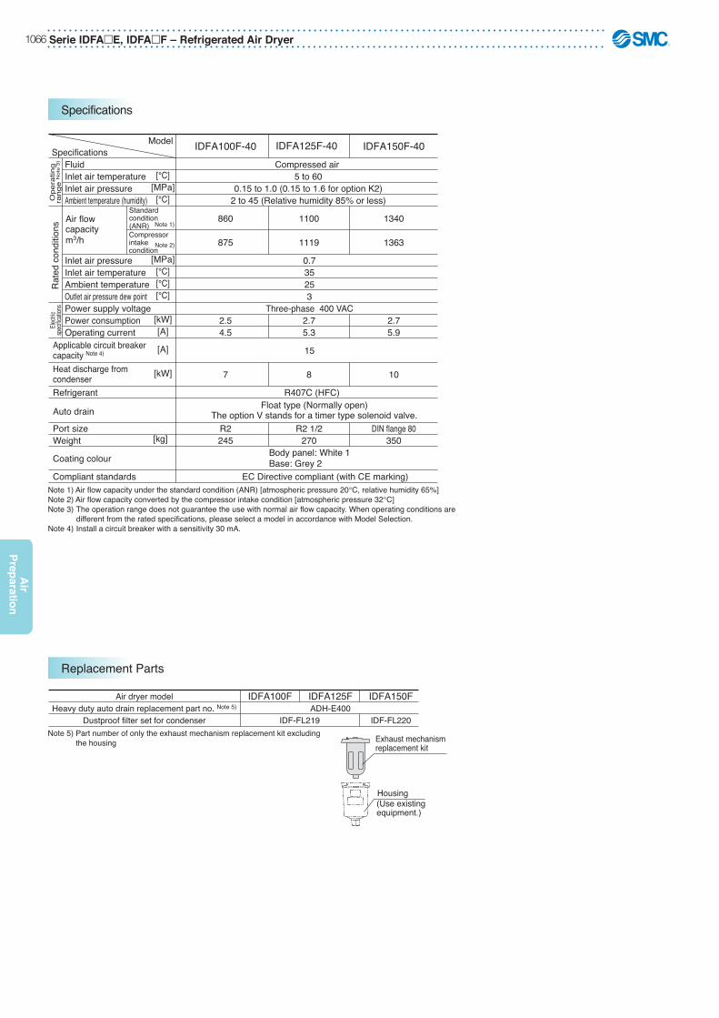
Exhaust mechanism replacement kit
Housing(Use existingequipment.)
Air dryer modelHeavy duty auto drain replacement part no. Note 5)
Dustproof filter set for condenser
IDFA100F
IDF-FL219
IDFA125FADH-E400
IDFA150F
IDF-FL220
Compressed air 5 to 60
0.15 to 1.0 (0.15 to 1.6 for option K2)2 to 45 (Relative humidity 85% or less)
0.7
15
R407C (HFC)
EC Directive compliant (with CE marking)
IDFA100F-40 IDFA125F-40 IDFA150F-40
860
875
35253
Three-phase 400 VAC
1100
1119
1340
1363
2.54.5
2.75.3
2.75.9
Float type (Normally open)The option V stands for a timer type solenoid valve.
Heat discharge fromcondenser
Applicable circuit breaker capacity Note 4)
7 8 10
R2245
R2 1/2270
DIN flange 80350
FluidInlet air temperatureInlet air pressureAmbient temperature (humidity)
Inlet air pressureInlet air temperatureAmbient temperatureOutlet air pressure dew pointPower supply voltagePower consumptionOperating current
Refrigerant
Auto drain
Port sizeWeight
Coating colour
Compliant standards
[°C][MPa]
[°C]
[MPa][°C][°C][°C]
[kW][A]
[A]
[kW]
[kg]
ModelSpecifications
Ope
ratin
gra
nge
Not
e 3)
Rat
ed c
ondi
tions
Air flow capacitym3/h
Standard condition (ANR)Compressor intake condition
Note 1)
Note 2)
Electr
icsp
ecific
ation
s
Body panel: White 1Base: Grey 2
Note 1) Air flow capacity under the standard condition (ANR) [atmospheric pressure 20°C, relative humidity 65%] Note 2) Air flow capacity converted by the compressor intake condition [atmospheric pressure 32°C] Note 3) The operation range does not guarantee the use with normal air flow capacity. When operating conditions are different from the rated specifications, please select a model in accordance with Model Selection. Note 4) Install a circuit breaker with a sensitivity 30 mA.
Note 5) Part number of only the exhaust mechanism replacement kit excluding the housing
Refrigerated Air Dryer – Serie IDFAE, IDFAF 1067
Air
Pre
par
atio
n
For more product options and details see our specifi c catalogues or on-line information.
Optional Accessories
Features Applicable dryer
IDFA3E to 75EPrevents a reduction in the performance of the air dryer, even in dusty atmospheres.
Specifications
Max. ambienttemperature
40ºC
Dust-protectingfilter set Note)
Prevents dust to enter air dryer.Extended life of dryer. Filtration rate 3μm IDFA3E to 75E
Pre-filter
(IDF-FL209) (IDF-FL202 to 208, 213, 214)
A(20)
B(1
0)
(20)
50
Part no. Applicable dryer Weight [g]A BIDFA3EIDFA4EIDFA6EIDFA8EIDFA11EIDFA15EIDFA22EIDFA37EIDFA55EIDFA75E
Example) To obtain the amount of condensed water when the pressure is applied to air up to 0.7 MPa with an air compressor, then cooled down to 25ºC. Given an ambient tempera-ture at 30ºC and a relative humidity 60%.
1. Trace the arrow mark from the point A at an ambient temperature 30ºC to obtain the intersection B on the curved line for the relative humidity 60%.
2. Trace the arrow mark from the intersection B to obtain the intersection D on the pressure charac-teristic line for 0.7 MPa.
3. Trace the arrow mark from the intersection D to obtain the intersection E.
4. The intersection E is the dew point under pressure 0.7 MPa with an ambient temperature 30ºC and a relative humidity 60%. The value for E is 62ºC.
5. Trace the intersection E upward, and trace from the intersection D leftward to obtain the intersection C.
6. The intersection C is the amount of moisture included in the compressed air 1 m3 at 0.7 MPa and a pressure dew point 62ºC. The amount of moisture is 18.2 g/m3.
7. Trace the arrow mark, starting from F for cooling temperature 25ºC (pressure dew point 25ºC) to obtain the intersection G on the pressure charac-teristic line for 0.7 MPa.
8. From the intersection G, trace the arrow mark to obtain the intersection H on the vertical axis.
9. The intersection H is the amount of moisture included in the compressed air 1 m3 at 0.7 MPa, and a pressure dew point 25ºC. The amount of moisture is 3.0 g/m3.
10. Therefore, the amount of condensed water is as follows (per 1 m3):
The amount of moisture at the intersection C – the amount of moisture at the intersection H = the amount of condensed water18.2 – 3.0 = 15.2 g/m3
Example) To obtain the atmospheric pressure dew point at a pressure dew point 10ºC and a pressure 0.7 MPa.
1. Trace the arrow mark → starting from the point A at a pressure dew point 10ºC to obtain the intersection B on the pressure characteris-tic line for 0.7 MPa.
2. Trace the arrow mark → starting from the point B to obtain the intersection C at the dew point under atmospheric pressure.
3. The intersection C is the conversion value –17ºC under atmospheric pressure dew point.
How to read the dew point conversion chart
How to calculate the amount of condensed water
Refrigerated Air Dryer – Serie IDFAE, IDFAF 1069
Air
Pre
par
atio
n
For more product options and details see our specifi c catalogues or on-line information.
Dimensions
IDFA3E to 15E
ModelIDFA3EIDFA4EIDFA6EIDFA8EIDFA11EIDFA15E
Port size[mm]
Rc 3/8Rc 1/2
Rc 3/4
Rc 1
A226
270
300
410453455
485
603
473
498
568
578
67
31
41
125
42
54
304
283
355
396
33
80
87
36
15
154
240
284
21
80
101
330
275
300
380
—
314
1513
15
16
B C D E F G K∗ L∗ M∗ N∗ P Q
4 x ø13
A
C
N
M
LP
K
FG
DInlet
Outlet
E
B
Q
IDFA4E to 11E
4 x ø13
A
C
N
M
LP
K
B
Q
In case of IDFA15E
FG
D
InletOutlet
E
∗ Meaning the foot dimensions for the IDFA3E.
Dimensions
FG
DInlet
Outlet
E
In case of IDFA3E
A
C
Serie IDFAE, IDFAF – Refrigerated Air Dryer1070
Air
Prep
aration
Dimensions
IDFA22E, IDFA37E
IDFA55E, IDFA75E
F
4 x ø13
C
K
LP
N
M
G A
D
EB
ModelIDFA22EIDFA37E
Port size[mm]
R 1R 11/2
A
290775855
623 134 405 698 93 13 25 85600680
340 —
B C D E F G K L M N P QDimensions
ModelIDFA55EIDFA75E
Port size[mm]
R 2
A
470 855800900
(128) (273)(868)(968)
(110) 13 500 75 700 526 (110)
B C D E F G K L M N P Q
519
RDimensions
F
4 x ø13
C
N
M
D
Q
AR
B
E
G
LP
K
Refrigerated Air Dryer – Serie IDFAE, IDFAF 1071
Air
Pre
par
atio
n
For more product options and details see our specifi c catalogues or on-line information.
Dimensions
[mm]
BE
D
GA
F
PL
K
N
M
C
B ED
G A
F
LP
K
N
C
M
IDFA100F/125F
IDFA150F
DimensionsModel
IDFA100FIDFA125F
Port sizeR2
R2 1/2
A670700
B
1130
C
1276
D
267
E460655
F
1375
G335350
K
20
L
712
M107 78
N700935
P
752
DimensionsModel
IDFA150FPort size
DIN flange 80A
950B
1300C
1332D
268E
720F
1432G
475K20
L990
M217
N935
P1030
IDFA100F/125F/150F
[mm]
Series IDG – Membrane Air Dryer1072
Air
Prep
aration
• Energy saving design.• Compatible with low dew points: -15ºC, -20ºC, -40ºC, -60ºC.• Power supply is not required.• Non-fluorocarbon.• Dew point indicator visually confirms air drying. IDG1
IDG30
IDG10
IDGDGIDG3030
Membrane Air DryerSeries IDG
Features
How to Order
1
51020
30506075
100
Size
Thread type
Option
Port size
IDG 10
01 1/802 1/403 3/8
Symbol Bore Size1 5 10 20 30— — — —
— —
04 1/2 —
3
—— — — — —
50—
—
60——
75——
100——
— None (Standard)P With fitting for purge air dischargeR Flow direction (Right Left)
Symbol Contents Size1 5 10 20 30
—
S With dew point indicator —
3
50
Standard equipment
60
75
100
Note) In the case of two or more options, indicate them alphabetically.
3
03
F G
Bracket Assembly (Accessory) Part No.
Part no. Applicable model
BM59BM61BM63BM64
IDG3, 5IDG10IDG20
IDG30A/50ABM65 IDG60/75/100
∗ With cap bolts and spring washers
Standard dew point and air flow rate
—HLS
-20°C standard-15°C high dewpoint-40°C low dewpoint-60°C super low dewpoint
10———
Symbol Dew Point 12525——
35050——
5100100
——
10200200
——
2030030075—
30500500110
—
5060060017050
60750750240100
7510001000300150
100Flow rate by size outlet ir flow rate [l/min (ANR)]
The IDG can be combined with SMC standard modular filters and regulators.For details on how to order complete assemblies, please contact SMC.
F
Note) For replacement elements and dewpoint indicators, please contact SMC.
Series AC - Air Preparation - page 1076Series TU - Tubing - page 1223Series KQ2 - Fittings - page 1184Series PF2A - Digital Flow Switch for Air - page 1309 Series IS10 - Pressure Switch for Air - page 1093Series ZSE/ISE0A - Digital Pressure Switch for Air - page 1273
Note 1) With no freezing.Note 2) ANR indicates the flow rate converted to the value for 20C at atmospheric pressure.Note 3) Includes dew point indicator purge air flow rate of 1 l/min (ANR) (inlet air pressure at 0.7MPa) (except IDG1, IDG3 and IDG5 ).
IDG3
31
25
6
Inlet air temperature [°C] Note 1)
Ambient temperature [°C]
Inlet air pressure[MPa]
Outlet air atmosphericpressure dew point [°C]
Inlet air flow rate[l/min] (ANR) Note 2)
Outlet air flow rate[l/min] (ANR) Purge air flow rate[l/min] (ANR) Note 3)
Inlet air temperature [°C]Inlet air saturation temperature [°C] Ambient temperature [°C]
Inlet air pressure MPa
Dew point indicator purge air flow ratePort size (nominal size B)Weight [kg](with bracket)
1l/min (ANR) inlet air pressure at 0.7MPa
Standard dew point – 20°C
Rang
e of o
perat
ingco
nditio
nsSt
anda
rd p
erfo
rman
ceco
nditio
nsSta
ndard
perform
ance
Standard Specifications/Single Style (Standard Dew Point –15°C)
Ambient temperature [°C]Outlet air atmosphericpressure dew point [°C]
Inlet air pressure [MPa]
Inlet air temperature [°C]Inlet air saturation temperature [°C] Ambient temperature [°C]
Inlet air flow rate[l/min] (ANR) Note 2)
Outlet air flow rate[l/min] (ANR) Purge air flow rate[l/min] (ANR) Note 3)
Inlet air pressure[MPa]
Dew point indicator purge air flow ratePort size (nominal size B)Weight [kg](with bracket)
Standard dew point –15 °C
Compressed air
1 l /min (ANR) inlet air pressure at 0.7MPa
Note 1) With no freezing.Note 2) ANR indicates the flow rate converted to the value for 20C at atmospheric pressure.Note 3) Includes dew point indicator purge air flow rate of 1l/min (ANR) (inlet air pressure at 0.7MPa) (except IDG3H and IDG5H).
0.78(0.91)
0.81(0.94)
Series IDG – Membrane Air Dryer1074
Air
Prep
aration
Specifications
Standard Specifications/Single Style (Standard Dew Point –40°C)
ModelStandard dew point –40°C
Fluid Compressed air
Inlet air temperature [°C] Note1) –5 to 50Ambient temperature [°C] Note1)
Inlet air temperature [°C] Inlet air saturation temperature [°C]Ambient temperature [°C]
Outlet air atmospheric pressure dew point [°C]
Inlet air flow rate[l/min] (ANR) Note 2)
Outlet air flow rate[l/min] (ANR) Purge air flow rate[l/min] (ANR) Note 3)
Inlet air pressure[MPa]
Dew point indicator purge air flow ratePort size (nominal size B)Weight [kg](with bracket)
Inlet air pressure [MPa] 0.3 to 1.0
Range
of ope
rating
conditi
onsSta
ndard
perform
ance
–5 to 50
–40
IDG30LA IDG50LA IDG60LA IDG75LA IDG100LA
93 135 224 308 400
0.7252525
1 l/min (ANR) inlet air pressure at 0.7MPa
75 110 170 240 300
18 25 54 68 100
0.78(0.91)
0.81(0.94)
1.56(1.71)
1.69(1.84)
1.82(1.97)
3/8, 1/21/4, 3/8
Note 1) When using the product in the temperature range between –5°C and 5°C, prevent water droplets from entering the inlet port. (No freezing of the fluid)Note 2) ANR indicates the flow rate converted to the value for 20C at atmospheric pressure.Note 3) Includes dew point indicator purge air flow rate of 1l/min (ANR) (inlet air pressure at 0.7MPa).
Stan
dard
per
form
ance
cond
itions
Standard dew point –60°C
Compressed air
–5 to 500.3 to 1.0
–5 to 50
–60
IDG60SA IDG75SA IDG100SA
75 140 230
0.7
252525
1 l/min (ANR) inlet air pressure at 0.7MPa
50 100 150
27 54 85
1.56(1.71)
1.69(1.84)
1.82(1.97)
3/8, 1/2
Standard Specifications/Single Style (Standard Dew Point –60°C)
Model
Fluid
Inlet air temperature [°C] Note1)
Ambient temperature [°C] Note1)
Outlet air atmospheric pressure dew point [°C]
Inlet air pressure[MPa]
Range
of ope
rating
conditi
onsSta
ndard
perform
ance
Inlet air temperature [°C] Inlet air saturation temperature [°C]Ambient temperature [°C]
Inlet air flow rate[l/min] (ANR) Note 2)
Outlet air flow rate[l/min] (ANR) Purge air flow rate[l/min] (ANR) Note 3)
Inlet air pressure[MPa]
Dew point indicator purge air flow ratePort size (nominal size B)Weight [kg](with bracket)Note 1) When using the product in the temperature range between –5°C and 5°C, prevent water droplets from entering the inlet port. (No freezing of the fluid)Note 2) ANR indicates the flow rate converted to the value for 20C at atmospheric pressure.Note 3) Includes dew point indicator purge air flow rate of 1l/min (ANR) (inlet air pressure at 0.7MPa).
Stan
dard
per
form
ance
cond
itions
Membrane Air Dryer – Series IDG 1075
Air
Pre
par
atio
n
For more product options and details see our specifi c catalogues or on-line information.
Performance Charts
0 4 8 12 16
IDG1
Outlet air flow rate [l/min [ANR]]
Outle
t air a
tmos
pheri
c pres
sure
dew
point
[°C]
−40
−30
−20
−10
0
0 100 200 300 400 500
IDG30A, 30HA
Outlet air flow rate [l/min [ANR]]
Outle
t air a
tmos
pheri
c pres
sure
dew
point
[°C]
0 100 200 300
IDG20, 20H
Outlet air flow rate [l/min [ANR]]
Outle
t air a
tmos
pheri
c pres
sure
dew
point
[°C]
−40
−30
−20
−10
0
0 40 80 120 160
IDG10, 10H
Outlet air flow rate [l/min [ANR]]
Outle
t air a
tmos
pheri
c pres
sure
dew
point
[°C]
−40
−30
−20
−10
0
0 10 20 30 40
IDG3, 3H
Outlet air flow rate [l/min [ANR]]
Outle
t air a
tmos
pheri
c pres
sure
dew
point
[°C]
−40
−30
−20
−10
0
0 20 40 60 80
IDG5, 5H
Outlet air flow rate [l/min [ANR]]
Outle
t air a
tmos
pheri
c pres
sure
dew
point
[°C]
−40
−30
−20
−10
0
−50
−40
−30
−20
−10
0
0 200 400 600 800
IDG60, 60H
Outlet air flow rate [l/min [ANR]]
Outle
t air a
tmos
pheri
c pres
sure
dew
point
[°C]
−50
−40
−30
−20
−10
0
0 200 400 600 800
IDG50A, 50HA
Outlet air flow rate [l/min [ANR]]
Outle
t air a
tmos
pheri
c pres
sure
dew
point
[°C]
−50
−40
−30
−20
−10
0
P1 = 0.3 MPa
P1 = 0.5 MPa
P1 = 0.7 MPa
IDG1
P1 = 0.3 MPa
P1 = 0.5 MPa
P1 = 0.7 MPa
P1 = 0.3 MPa
P1 = 0.5 MPa
P1 = 0.7 MPa
P1 = 0.3 MPa
P1 = 0.5 MPa
P1 = 0.7 MPa
P1 = 0.3 MPa
P1 = 0.5 MPa
P1 = 0.7 MPa
P1 = 0.3 MPa
P1 = 0.5 MPa
P1 = 0.7 MPa
IDG5IDG5H
P1 = 0.3 MPa
P1 = 0.5 MPa
P1 = 0.7 MPa
IDG10IDG10H
IDG60IDG60H
IDG30AIDG30HA
IDG50A
IDG50HA
P1 = 0.3 MPa
P1 = 0.5 MPa
P1 = 0.7 MPa
IDG20IDG20H
IDG3
IDG3H
Standard dew point…−20°C [Symbol: Nil], −15°C [Symbol: H]
Conditions: Inlet air temperature 25°C (saturated air), Ambient temperature 25°C, P1: Inlet air pressure, Tube for purge air discharge (Option: P): NoneNote: Correcting outlet air flow rate is required depending on inlet air temperature. For model with fitting for purge air discharge (Option: P), the
outlet air atmospheric pressure dew point may become higher depending on the tube length for purge air discharge. For other models, if the tube length is 5 m or less, a rise of the outlet air at the atmospheric pressure dew point will be 1°C or less.
Series IDG – Membrane Air Dryer1076
Air
Prep
aration
Performance Charts
0 40 80 120 160
IDG30LA, 50LA
Outlet air flow rate [l/min [ANR]]
Outle
t air a
tmos
pheri
c pres
sure
dew
point
[°C]
0 400 800 1200 1600
IDG100, 100H
Outlet air flow rate [l/min [ANR]]
Outle
t air a
tmos
pheri
c pres
sure
dew
point
[°C]
−50
−40
−30
−20
−10
0
0 200 400 600 800 1000
IDG75, 75H
Outlet air flow rate [L/min [ANR]]
Outle
t air a
tmos
pheri
c pres
sure
dew
point
[°C]
−50
−40
−30
−20
−10
0
−70
−60
−50
−40
−30
−20
−10
0
0 40 80 120 160 200 240
IDG60LA, 60SA
Outlet air flow rate [l/min [ANR]]
Outle
t air a
tmos
pheri
c pres
sure
dew
point
[°C]
−70
−60
−50
−40
−30
−20
−10
0
0 100 200 300 400
IDG100LA, 100SA
Outlet air flow rate [l/min [ANR]]
Outle
t air a
tmos
pheri
c pres
sure
dew
point
[°C]
−70
−60
−50
−40
−30
−20
−10
0
0 100 200 300
IDG75LA, 75SA
Outlet air flow rate [l/min [ANR]]
Outle
t air a
tmos
pheri
c pres
sure
dew
point
[°C]
−70
−60
−50
−40
−30
−20
−10
0 P1 = 0.3 MPa
P1 = 0.5 MPa
P1 = 0.7 MPa
P1 = 0.3 MPa
P1 = 0.5 MPa
P1 = 0.7 MPa
P1 = 0.3 MPa
P1 = 0.5 MPa
P1 = 0.7 MPa
P1 = 0.3 MPa
P1 = 0.5 MPa
P1 = 0.7 MPa
P1 = 0.3 MPa
P1 = 0.5 MPa
P1 = 0.7 MPa
P1 = 0.3 MPa
P1 = 0.5 MPa
P1 = 0.7 MPa
IDG75LA
IDG75SA
IDG60LA
IDG60SA
IDG50LA
IDG30LA
IDG100L
IDG100S
IDG100
IDG100H
IDG75
IDG75H
How to read the Performance Chart and to select the modelSolid lines and dashed lines beginning at the top indicate the performance at 25°C of inlet air temperature and P1 = 0.3 MPa, 0.5 MPa, and 0.7 MPa of inlet air pressure, respectively.
· In the case of 25°C of inlet air temperature and 45 [L/min] of outlet air flow rate Model 1: The atmosphere pressure dew point at P1 = 0.7 MPa: –25°C.
· In the case of 40°C of inlet air temperature and 45 [L/min] of outlet air flow rate
Example) Outlet air flow rate correction factor: 0.6(The correction factor differs depending on the model.
Corrected outlet air flow rate: 45 ÷ 0.6 = 75 [L/min] Model 1: Performing corresponding to –15°C of outlet atmosphere pressure dew point at P1 = 0.7 MPa.
Outlet air flow rate [L/min]
Model 1: P1 = 0.3 MPaModel 2: P1 = 0.3 MPa
0−40
−30
−20
−10
0
−15
−25
Outle
t air a
tmos
pheri
c pres
sure
dew
point
[°C]
45 75
P1 = 0.3 MPa
P1 = 0.5 MPa
P1 = 0.7 MPa
Model 1: P1 = 0.7 MPaModel 2: P1 = 0.7 MPa
Standard dew point…−40°C [Symbol: L], −60°C [Symbol: S]
Membrane Air Dryer – Series IDG 1077
Air
Pre
par
atio
n
For more product options and details see our specifi c catalogues or on-line information.
For more product options and details see our specifi c catalogues or on-line information.
• Advanced fluoropolymer that eliminates water condensation.• Vapour diffusing process ejects water to the outside.
Moisture Control TubeSeries IDK
Features
How to Order
Specifications
IDKMoisture controltube effective length
02 100
Symbol100200
Effective length100 mm200 mm
Moisture controltube O.D.
Symbol020406
O.D.2 mm4 mm6 mm
R
∗2 Inner sleeve
FluidMax. operating pressureOperating temperature [ºC]Operating environment ∗1
Min. bending radius ∗2 [mm]O.D. [mm]I.D. [mm]Quantity of moisture control tubesAccessories
Colour
Applicable fittingsMaterial
IDK02
102
1.2
Model IDK04Compressed air
0.7 MPa0 to 40 (No freezing)
Indoors, where product is not exposed to water (0 to 40ºC, Relative humidity 0 to 75%RH)204
2.5
2 pcs.
Inner sleeve 4 pcs. (already mounted into tube)
KQ2Fluoropolymer
IDK06
4064
Note 1) Use the moisture control tube in a line with a refrigerated air dryer and a mist separator installed in the upstream compressed air line. The condensation prevention performance may be lowered depending on the quality of the supply compressed air (oil, dew point).
Note 2) The inner sleeve is already mounted and cannot be removed. If the inner sleeve comes off, re-insert the sleeve before mounting the fitting.
Note 3) Do not cut the tube. ∗1 Use the product in an operating environment where humidity is
as low as possible. ∗2 The value at which the moisture control tube is bent or flattened at 20ºC.
Be careful not to bend or flatten the tube and the inner sleeve even if the value is more than the minimum bending radius.
Transparent Colour will change to brown over time, but the functions are not affected.
Necessary effective length = 180 x 1 x 1.7 x 0.4 120 mm
Check the presence of condensation.(1) Calculation method of volume ratio (Kv value)
Verify the presence of condensation.(2) Refer to the verification chart of condensation.
Check whether the volume ratio (Kv) and the supply air dew point intersect in the condensation area.With the conditions above, they intersect in the condensation area, meaning condensation will occur.
(1) Find the necessary length L from the length selection chart at basic conditions and Kv value.
(2) If your operating conditions are different from these basic conditions, apply a correction factor.Necessary effective length = Basic condition length L x Correction factor C1 x C2 x C3In the example circuit, the conditions which are different from the basic conditions are:Supply dew point: –20ºC (Atmospheric pressure dew point)Supply pressure: 0.3 MPaAmbient environment: 25ºC, 60%
Correction Factor C1 for Supply Air Dew PointSupply air dew point
[ºC]–10–20–30–40
Correction factorC121
0.50.25
Correction Factor C3 for Supply Pressure
0.30.40.50.60.7
Supply pressure[MPa]
Correction factorC30.40.71
1.251.6
Correction Factor C2 for Ambient Air Relative HumidityTemperature
Relative humidity
Correction factor C210ºC0.20.51.02.1
25ºC0.41.01.74.0
40ºC0.61.32.85.9
20%40%60%80%
Circuit conditions• Actuator : CUJB4-6D Bore size D : 4 mm Stroke s : 6 mm• Tube size : O.D. 6 mm x I.D. (d) 4 mm• Tube piping length l : 5 m• Supply air pressure : 0.3 MPa• Supply air dew point : –20ºC (Atmospheric pressure dew point)• Ambient environment : Temperature 25ºC, Humidity 60%
Select the length of moisture control tube.2
Check the presence of condensation.1
∗ Basic conditionsSupply dew point: –20ºC
(Atmospheric pressure dew point)
Supply pressure: 0.5 MPaAmbient environment:
25ºC, 40%
(a) Find the correction factors.• Supply air dew point correction factor C1 = 1• Ambient air dew point correction factor C2 = 1.7• Supply pressure correction factor C3 = 0.4
(b) Find the necessary effective length after correction.
Therefore, the moisture control tube IDK06-200 with effective length 20 cm should be used.
Series HED – Chemical Thermo - con1082
Air
Prep
aration
Chemical Thermo-conSeries HED
• Allows direct control of chemical temperature.• PFA wetted material.• Compact / Lightweight.• Operating temperature range: 10ºC TO 60ºC• Temperature stability: ±0.1ºC
Features
Series PF2D - Digital Flow Switch for Chemicals - www.smc.euSeries PF3W - Digital Flow Switch for Water - page 1317Series VX - Direct Operated 2 Port Solenoid Valve - page 1457Series LV - 2 Port Air Operated PFA Valves - www.smc.euSeries LQ - Fluoropolymer Fittings - www.smc.euSeries TL - PFA Tubing - www.smc.eu
Related Products
How to Order
007 BHED W 2
003005007
300 W500 W750 W
W Water-cooled
Cooling capacity
Radiating method2Power supply
AB
RS-485RS-232C
Communication
1319
1/2" x 3/8"3/4" x 5/8"
Tube sizeChemicalThermo-con
Single-phase: 180 to 242 VAC 50/60 Hz
Temperature controller + Heat exchanger
007 BHED C 2
003005007
300 W500 W750 W
Cooling capacity
Temperature controller2Power supply
AB
RS-485RS-232C
Communication
Single-phase: 180 to 242 VAC 50/60 Hz
Temperature controller
Heat exchanger
007 13
13
HED H W
003005007
300 W500 W750 W
Cooling capacity
Heat exchanger
WRadiating method
1319
1/2" x 3/8"3/4" x 5/8"
Tube size
Water-cooled
Note) The tube size should be specified when ordering.
Chemical Thermo - con – Series HED 1083
Air
Pre
par
atio
n
For more product options and details see our specifi c catalogues or on-line information.
Main Specifications
Note 1) The conditions are as follows. Circulating fluid: Water (Circulating flow rate 15 l/min, Set temperature 25ºC); Facility water temperature: 25ºC; Facility water flow rate: 5 l/min; Ambient temperature: 25ºCNote 2) For the compatibility between the circulating fluid and materials, please contact SMC. Note that the Chemical Thermo-con is not designed explosion proof so it is not suitable for flammable fluids.Note 3) Install the heat exchanger in the discharge side of a circulating pump. Do not use at location where a negative pressure is applied. The circulating fluid pump should be prepared by the customer.Note 4) The outline dimensions do not included protruding parts such as foot flange and tube.
HED003-HW13 HED003-HW19 HED005-HW13 HED005-HW19 HED007-HW13 HED007-HW19300 W600 W
750 W1800 W
Cooling capacity (Water) Note 1)
Heating capacity (Water) Note 1)
Cooling/Heating methodRadiating methodOperating temperature range
Peltier element (Thermoelectric device, Thermo-module)Water-cooled
10.0 to 60.0ºC (depending on the type of circulating fluid)Pure water, Hydrofluoric acid, Ammonia hydrogen peroxide solution, etc.
PFA0 (atmospheric pressure) to 0.35 MPa (0 to 50.75 PSI)
10 to 35ºC (no condensation)FEP, Stainless steel 304, Stainless steel 316
0.5 MPa (72.5 PSI)IN/OUT: FEP tube 3/8" x 1/4"5 to 10 l /min (1.3 to 2.6 g/m)
Temperature: 10 to 35ºC, Humidity: 35 to 80%RH (no condensation)W150 mm x D294 mm x H222 mm
(W5.91" x D11.6" x H8.74")
1/2" x 3/8"
W130 mm x D263 mm x H170 mm(W5.12" x D10.4" x H6.69")
HED003-C2AHED003-C2B
HED005-C2AHED005-C2B
HED007-C2AHED007-C2B
Applied heat exchanger HED003-HW13HED003-HW19
HED005-HW13HED005-HW19
HED007-HW13HED007-HW19
W150 mm x D294 mm x H222 mm(W5.91" x D11.6" x H8.74")
Approx. 14 kg (30.8 lb)Approx. 8 kg (17.6 lb) Approx. 15 kg (33 lb)
1/2" x 3/8" 1/2" x 3/8"3/4" x 5/8" 3/4" x 5/8" 3/4" x 5/8"
Heat Exchanger Specifications
Note 1) This value is for a stable load with no disturbance and cannot be achieved in determined operating conditions.Note 2) The outline dimensions do not included protruding parts such as the foot flange, screw and connector.Note 3) The temperature controller should be connected with a specific series of heat exchanger. If connected with a different series of heat exchanger, it may not operate normally. (The HED003 and HED005 series use the same connector, so be careful for incorrect wiring.)Note 4) The external sensor should be prepared by the customer.
HED003-C2ARS-485
HED003-C2BRS-232C
HED005-C2ARS-485
HED005-C2BRS-232C
HED007-C2ARS-485
HED007-C2BRS-232CCommunication
Control methodOperating temp. rangeTemperature stability Note 1)
Temperature sensor
Main functions
Ambient
Dimensions Note 2)
Mass
Powersupply spec.
Temperature controller model
Power supplyRated current
Cooling/Heating automatic shift PID control10.0 to 60.0ºC (no condensation)
Within 0.1ºC (with stable load)Resistance thermometer Pt100 , 3-wires, class A, 2 mA (for both internal control sensor and external sensor) Note 4)
Auto-tuning, Sensor fine adjustment, Offset, Learning control, External sensor control, Set value memory,Upper/lower temperature limit alarm, Output shutdown alarm, Remote ON/OFF, Leakage detection
Temperature: 10 to 35ºC, Humidity: 35 to 80%RH (no condensation)Single-phase: 180 to 242 VAC 50/60 Hz
5A3A 14AW140 mm x D350 mm x H215 mm
(W5.51" x D13.8" x H8.46")W100 mm x D320 mm x H215 mm
(W3.94" x D12.6" x H8.46")W165 mm x D447 mm x H215 mm
(W6.50" x D17.6" x H8.46")Approx. 8 kg (17.6 lb)Approx. 6 kg (13.2 lb) Approx. 13 kg (28.6 lb)
Temperature Controller Specifications
Note 3)
Series HED – Chemical Thermo - con1084
Air
Prep
aration
Maintenance
Please prepare back-up equipment as necessary to minimize the downtime.
1) Heat exchangerThe heat exchanger will not be repaired in principle. Only the return to SMC for an investigation within warranty will be accepted. The return unit has to be completely decontaminated with appropriate method such as use of neutralizing agent before return to SMC.
2) Temperature controllerThe temperature controller maintenance is only performed at SMC's site. On the other hand, following parts have a limited life and need to be replaced before th life ends.
Parts Life ExpectationDescription Expected life
5 to 10 years
5 to 10 years
Fan
DC power supply
Display panel 50,000 hours(approx. 5 years)
Possible failureLack of fan cooling because of the bearing life time. It will activate theoverheat protection of DC power supply and generate an alarm.
End life of electrolytic condenser. It will generate DC power supply alarm.
End life of LCD display backlight.
The values shown on the performance chart are representative and not guaranteed. Allow a safety margin when choosing the product.
Pressure Loss in Circulating Fluid Circuit <Condition> Water
Pressure Loss in Facility Water Circuit <Condition> Water
Series HED – Chemical Thermo - con1086
Air
Prep
aration
Dimensions
2000
66
2550
370(10)35010
732
667
305(10)28510
(140)
(30)
(20)
32020
26322
5 2Model No. plate(Heat exchanger) Model No. plate
(Controller)
Fluid leak sensor
100
215
110
130
103
65
27
21
170143120
41OFF
O N
POWER
Power supply switch
Display panelSignal cable 5 m
DC cable 5 m
Circulating fluidoutlet
AL
OUT
SI
PURGEIN
INWATERIN
CHEMICALPURGE
OUT
WATEROUT
Circulating fluid inlet
Facilitywater outlet3/8" x 1/4"
Purge outlet(M5)
Purge inlet(M5)
Facilitywater inet3/8" x 1/4"
75 29
97
797553
3528AC
COMMUNICATION
DC
SIGNAL
ALARM
FGBBAFG-+EXT.SENSORREMOTE ON/OFF
Terminal block
DC connector
Power supplyconnector
Communication connector(The RS-232C uses only lower side connector)
Alarm output connector
Signal connector
2000
6 2010
06
400(10)38010
7 1711
67
330(10)31010
Fluid leak sensor
(140)(18)294
2
(30)35020
18
5
Model No. plate (Controller)
Model No. plate (Heat exchanger)
140
215
22218
7
177
4442
150
122
7529
OFF
O N
POWER
Power supply switch
Display panelAL
IN
OUTSI
INWATER
INPURGE
CHEMICAL
PURGEOUT
WATEROUT
Facilitywater outlet3/8" x 1/4"
Circulating fluid inlet
Purge outlet(M5)
Purge inlet(M5)
Circulating fluid outlet
Facilitywater inlet3/8" x 1/4"
Signal cable 5 m
DC cable 5 m
110 69 49 29
79 75
56
3429
FGBBAFG-+EXT.SENSORREMOTE ON/OFF
COMMUNICATION
AC
ALARMSIGNAL
DC
Signal connector
DC connector Power supplyconnector
Terminal block
Communication connector(The RS-232C uses only right side connector)
Alarm output connector
Power Supply Cable(Accessory)Connector: IEC60320 C13 or equivalentCable: 14AWG, O.D. ø8.4
Wire colourBlack 1Black 2
Green/Yellow
Content180 to 242 VAC180 to 242 VAC
PE
HED003-W2
Power Supply Cable(Accessory)Connector: IEC60320 C13 or equivalentCable: 14AWG, O.D. ø8.4
Wire colourBlack 1Black 2
Green/Yellow
Content180 to 242 VAC180 to 242 VAC
PE
Heat exchangerHED005-HW
Temperature controllerHED005-C2
Heat exchangerHED003-HW
Temperature controllerHED003-C2
HED005-W2
Circulating Fluid Tube SizeHeat exchanger model
HED003-HW13HED003-HW19
Circulating fluid tube size1/2" x 3/8"3/4" x 5/8"
Circulating Fluid Tube SizeHeat exchanger model
HED005-HW13HED005-HW19
Circulating fluid tube size1/2" x 3/8"3/4" x 5/8"
Chemical Thermo - con – Series HED 1087
Air
Pre
par
atio
n
For more product options and details see our specifi c catalogues or on-line information.
Dimensions
2000
717
116
7
330(10)31010
Fluid leak sensor
(140)
2
(32)44720
(18)29418
5
Model No. plate (Controller)
Model No. plate (Heat exchanger)
145
132 83 33
189
109
149
33
COMM
UNICA
TION
ALAR
M
AC
FGBBAFG-+EXT.SENSORREMOTE ON/OFF
SIGNALDC
Terminal block
DC connector
Signal connector
Communication connector∗ The RS-232C uses only upper side connector.
Alarm output connector
Fan
Power supplyconnector
Power Supply Cable(Accessory)Connector: DDK CE05-6A18-10SD-D-BSSCable: 12AWG, O.D. ø11.8
Wire colourBlack 1Black 2
Green/Yellow
Content180 to 242 VAC180 to 242 VAC
PE
215
165
222
187
177
44
42
150
122
7529
OFF
O N
POWER
Power supply switch
Display panelALSI
OUT
OUT
ININ
WATER
INPURGE
CHEMICAL
PURGEOUT
WATER
Circulating fluid inlet
Facilitywater outlet3/8" x 1/4"
Purge outlet(M5)
Purge inlet(M5)
DC cable 5 m
Signal cable 5 m
Circulatingfluid outlet
Facility water inlet3/8" x 1/4"
Heat exchangerHED007-HW
Temperature controllerHED007-C2
Circulating Fluid Tube SizeHeat exchanger model
HED007-HW13HED007-HW19
Circulating fluid tube size1/2" x 3/8"3/4" x 5/8"
66
110
27.5
12.5
66
140
499(12)47512
HED007-W2
Series HRS – Thermo - Chiller1088
Air
Prep
aration
Thermo-ChillerSeries HRS
• Space-saving product as it is compact and lightweight.• Increase/decrease of the circulating fluid using two electronic expansion valves.• Temperature range setting: 5 to 40ºC• Temperature stability: ±0.1ºC
Features
HRS012-AF-20HRS012-WF-20
Product Recommendation
Stocked items for fast delivery Series PF3W - Digital Flow Switch for Water - page 1317Series ZSE/ISE80 - Digital Pressure Switch for Fluids - page 1290Series VNB - 2 Port Air Operated Valves - page 1466Series VXZ - Pilot Operated 2 Port Solenoid Valves - page 1451
Related Products
HRS018-AF-20HRS018-WF-20
HRS024-AF-20HRS024-WF-20
018 A 20HRSSingle-phase 200 to 230 VAC
OptionSymbol
—BJMTG
NoneWith earth leakage breakerWith automatic water supply functionApplicable to DI water (deionized water) pipingHigh-lift pump Note 1)
For more product options and details see our specifi c catalogues or on-line information.
Specifications ∗ There are different values from standard specifications.
Note 1) For water-cooled refrigerationNote 2) It should have no condensation.Note 3) If clear water is used, use water that conforms to Water Quality Standards of the Japan
Refrigeration and Air Conditioning Industrial Association (JRA GL-02-1994 cooling water system - circulating type - make-up water).
Note 4) q Ambient temperature: 25°C, w Circulating fluid temperature: 20°C, e Rated circulating fluid flow rate, r Circulating fluid: Clear water, t Facility water temperature: 25°CRefer to the cooling capacity graph on page 3 for details.
Note 5) Use a 15% ethylene glycol aqueous solution if operating in a place where the circulating fluid temperature is 10°C or less.
Note 6) Outlet temperature when the circulating fluid flow is rated flow, and the circulating fluid outlet and return port are directly connected. Installation environment and the power supply are within specification range and stable.
Note 7) The capacity at the Thermo-chiller outlet when the circulating fluid temperature is 20°C.Note 8) Required min. flow rate for cooling capacity or maintaining the temperature stability.
The specification of the cooling capacity and the temperature stability may not be satisfied if the flow rate is lower than the rated flow. (In such a case, use a by-pass piping set (sold separately).)
Note 9) Purchase an earth leakage breaker with current sensitivity of 30 mA separately. (A product with an optional earth leakage breaker (option B) is also available.)
Note 10) Front: 1 m, height: 1 m, stable with no load, Other conditions → Note 4) Note 11) Weight in the dry state without circulating fluidsNote 12) Required flow rate when a load for the cooling capacity is applied at a circulating
fluid temperature of 20°C, and rated circulating fluid flow rate and facility water temperature of 25°C.
Note 13) It is not provided for HRS050.
Model HRS012-A-20 HRS012-W-20 HRS018-A-20 HRS018-W-20Cooling methodRefrigerantControl methodAmbient temperature/humidity Note 2)
Wetted parts material Temperature range [°C]Pressure range [MPa]Required flow rate Note 12) (50/60 Hz) [L/min]Inlet-outlet pressure differential of facility water [MPa]Port sizeWetted parts materialPower supply
Circuit protector [A]Applicable earth leakage breaker capacity Note 9) [A]Rated operating current [A]Rated power consumption Note 4) (50/60 Hz) [kVA]
Noise level Note 10) (50/60 Hz) [dB]
Accessories
Weight Note 11) [kg]
PID controlTemperature: 5 to 40°C, High-temperature environment specifications (option): 5 to 45°C, Humidity: 30 to 70%
Alarm code list sticker 1, Ferritic core (for communication) 1 pc.Power supply cable should be ordered the option (sold separately) or prepared by the customer.
Conversion fitting for circulating fluid + Conversion fitting for drain outletHRS012-A-, HRS018-A-, HRS024-A-This fitting changes the port size for circulating fluid from Rc1/2 to G1/2 or NPT1/2, and for drain from Rc 3/8 to G3/8 or NPT3/8.It is not necessary to purchase this when pipe thread type F or N is selected in “How to Order” since it is included in the product.
Conversion fitting forcirculating fluid
Material: Stainless steel
2 pcs./set
Conversion fitting fordrain outlet
Material: POM
1 pc.
w Piping Conversion Fitting (For Air-Cooled Refrigeration)
When the options, with automatic water supply function “-J”, or high-lift pump “-T” are selected, purchase r piping conversion fitting (for option), too.
HRS050-A-This fitting changes the port size for circulating fluid from Rc1/2 to G1/2 or NPT1/2, and for drain from Rc 1/4 to G1/4 or NPT1/4.It is not necessary to purchase this when pipe thread type F or N is selected in “How to Order” since it is included in the product.
When the option, with automatic water supply function “-J”, is selected, purchase r piping conversion fitting (for option), too.
Bracket for earthquakes Prepare the anchor bolts (M8) which are suited to the floor material by the customer.(Anti-quake bracket thickness: 1.6 mm)
HRS012/018/024HRS050
Symbol
HRS050--
HRS012--HRS018--HRS024--
Part No. (for single unit)
HRS-TK001
HRS-TK002
Applicable model
HRS050-A-G thread conversion fitting setNPT thread conversion fitting set
HRS-EP009HRS-EP010
Part No.
Applicable modelHRS012-A-HRS018-A-HRS024-A-
G thread conversion fitting set
NPT thread conversion fitting set
HRS-EP001
HRS-EP002
Part No.
Conversion fitting forcirculating fluid
Material: Stainless steel
2 pcs./set
Conversion fitting fordrain outlet
Material: Stainless steel
1 pc.
Thermo - Chiller – Series HRS 1091
Air
Pre
par
atio
n
For more product options and details see our specifi c catalogues or on-line information.
Protrusion whenthe conversionfitting for facility
water is mountedApprox. 37 mm
Protrusion whenthe conversionfitting for facility
water is mountedApprox. 37 mm
Conversion fitting forcirculating fluid
Material: Stainless steel
2 pcs./set
Conversion fitting forfacility water
Material: Stainless steel
2 pcs./set
Conversion fitting fordrain outlet
Material: POM
1 pc.
Conversion fitting for circulating fluid + Conversion fitting for facility water + Conversion fitting for drain outletHRS012-W-, HRS018-W-, HRS024-W-
Conversion fitting for automatic water supply inlet
Conversion fitting for drain outlet
This fitting changes the port size for circulating fluid from Rc1/2 to G1/2 or NPT1/2, for facility water from Rc3/8 to G3/8 or NPT3/8, and for drain from Rc3/8 to G3/8 or NPT3/8. It is not necessary to purchase this when pipe thread type F or N is selected in “How to Order” since it is included in the product.
e Piping Conversion Fitting (For Water-Cooled Refrigeration)
When the options, with automatic water supply function “-J”, or high-lift pump “-T” are selected, purchase r piping conversion fitting (for option), too.
r Piping Conversion Fitting (For Option)
This fitting changes the port size for option-J “With Automatic Water Supply Function” from Rc3/8, Rc3/4 to G3/8, G3/4 or NPT3/8, NPT3/4.It is not necessary to purchase this when pipe thread type F or N is selected in “How to Order” since it is included in the product.
This fitting changes the port size for drain outlet for option-T “High-lift Pump” from Rc1/4 to G1/4 or NPT1/4.It is not necessary to purchase this when pipe thread type F or N is selected in “How to Order” since it is included in the product.
Conversion fitting forautomatic water supply inletMaterial: Stainless steel
1 pc. of each/set
HRS050-W-This fitting changes the port size for circulating fluid from Rc1/2 to G1/2 or NPT1/2, for facility water from Rc3/8 to G3/8 or NPT3/8, and for drain from Rc 1/4 to G1/4 or NPT1/4.It is not necessary to purchase this when pipe thread type F or N is selected in “How to Order” since it is included in the product.
When the option, with automatic water supply function “-J”, is selected, purchase r piping conversion fitting (for option), too.
Serial communication (RS-485/RS-232C) connectorD-sub female receptacle
HRS050-W
Series IDH – Thermo - dryer1094
Air
Prep
aration
• Dehumidification function (dryer).• Pressure regulation funtion (regulator).• Cleaning function (filter).• Temperature control function (heater).
Thermo - dryerSeries IDH
Features
How to Order
23IDHA 6
Size
46
Rated airflow capacity
400 l/min [ANR]600 l/min [ANR]
Size
Voltage
Combination of built-in products
—AB
Regulator
Filter (AMH)—
Filter (AME)——
Symbol
Symbol Voltage23 Single-phase 230 VAC (50/60 Hz)
Note) Other voltages available:100 VAC, 200 VAC
Note) Filter AMH: Micro mist separator with pre-filter. Filter AME: Super mist separator
ModelSpecifications
Compressed air
5 to 40°C0.3 to 1.0 MPa
15 to 35°C (Relative humidity 85% or less)15 to 30°C
0.15 to 0.85 MPa(The inlet air pressure should be at least 0.15 MPa higher than the outlet air pressure.)
0.7 MPa35°C30°C30°C10°C
±0.1°C±0.5°C (including accuracy of the sensor)
100 to 500 l/min [ANR] 200 to 800 l/min [ANR]
400 l/min [ANR] 600 l/min [ANR]
FluidAir flow capacityInlet air temperatureInlet air pressureAmbient temperatureOutlet air temperature adjustment range
Outlet air set pressure range
Air flow capacityInlet air pressureInlet air temperatureAmbient temperatureOutlet air set temperature Outlet air pressure dew pointOutlet air temperature stability Outlet air temperature display accuracy
Power supply Note 4)
Operating currentEarth leakage breaker capacityCompressor inputHeater inputNominal filtration ratingCleanliness of the filter outlet side
180/200 W 50/60 Hz220 W
0.01 μm (99.9% filtration efficiency)Particles of 0.3 μm or more: 3.5 particles/l [ANR] or less
Heater operation, PID control
385/440 W 50/60 Hz420 W
R134a/0.14 kg52 dB(A)
26 kg
Temperature control methodRefrigerant type/Refrigerant charge Noise level (reference value) Note 6)
Low Voltage Directive: 2006/95/EC EMC Directive: 2004/108/EC
R134a/0.26 kg55 dB(A)
37 kg
Single–phase 230 VAC(50/60 Hz)
2.1 A5 A
Single–phase 230 VAC(50/60 Hz)
4.8 A10 A
Note 1) ANR is the value at 20ºC, atmospheric pressure, and relative humidity of 65%.
Note 2) The upper limit of the settable outlet air temperature varies depending on the conditions even within the operating range. Be sure to read the selec-tion document before selecting the models.
Note 3) Performance when the operation of each part is stable without fluctuations in operating conditions and power supply
Note 4) Keep the voltage within -5 to +10% of the rated voltage. If there is voltage fluctuation, the outlet air temperature stability may decrease. So if highly accurate temperature adjustment is required, please use a stable power supply to make the voltage fluctuation smaller.
Note 5) The specification changes depending on the cleanliness of the inlet side air. It may take time until the cleanliness of the filter outlet side air stabilises immediately after start of operation. The filter performance only applies to the built-in type filter.
Note 6) 1 m in front of the product, 1 m in height, without load, stable conditions
Note1) 2)
Note 3)
IDHA4-23 IDHA6-23
Standard Specifications
Series AMH - Micro Mist Separator with Pre-filter - www.smc.euSeries AME - Super Mist Separator - www.smc.euSeries AC - Air Preparation - page 1076Series TU - Tubing - page 1223Series KQ2 - Fittings - page 1184Series PF2A - Digital Flow Swith for Air- page 1309 Series ZSE/ISE0A - Digital Pressure Switch for Air - page 1273Series VNB - 2 Port Air Operated Valves - page 1466Series VXZ - Pilot Operated 2 Port Solenoid Valves - page 1451
Related Products
Thermo - dryer – Series IDH 1095
Air
Pre
par
atio
n
For more product options and details see our specifi c catalogues or on-line information.
Specifications
10 min
1st emergency stop
2nd emergency stop
Automatic resetAutomatic resetRestart (manually)
The operation does not stop during temperature error.
3rd emergency stop
Within 60 min
Temperatureerror signal
Normalisation of temperature error
10 min
60 min
4th emergency stop
3rd emergency stop
1st emergency stop
4th emergency stop
2nd emergency stop
Closed
Open
Operating signal
Error signalN.O.
(a contact)Error signalN.C.
(b contact)
Note 1)Start of operation (manually)
5th emergency stop
Note 2)
Closed
Open
Closed
Open
Note 1)
Operating signal N.O. (a contact)Error signal N.C. (b contact)Error signal N.O. (a contact)
Terminal no.1-23-44-5
Description of operationClose after 10 minutes of operationOpen at an emergency stop or set temperature errorClose at an emergency stop or set temperature error
Contact capacityResistance load 2 A,Induction load 80 VA,
Lamp load 100 W
Minimum load
5 VDC 2 mA
Description
Output signal timing chart
Note 1) The operation can be started or restarted (manually) by the operation stop switch mounted on the thermo-dryer or a remote switch prepared by the user. Note 2) When emergency stop is generated 5 times in an hour or the heater protection equipment (thermo-stat) is operated, the emergency stop status will be held. At this time, the dryer can be restarted by reset operation using the switch stated in Note 1.
Example) To obtain the atmospheric pressure dew point at a pressure dew point 10°C and a pressure 0.7 MPa.
1. Trace the arrow mark starting from the point A at a pressure dew point 10°C to obtain the intersection B on the pressure characteris-tic line for 0.7 MPa.
2. Trace the arrow mark starting from the point B to obtain the intersection C at the dew point under atmospheric pressure.
3. The intersection C is the conversion value –17°C under atmospheric pressure dew point.
How to read the dew point conversion chart
Example) To obtain the amount of condensed water when the pressure is applied to air up to 0.7 MPa with an air compressor, then cooled down to 25°C. Given an ambient temperature at 30°C and a relative humidity 60%.
1. Trace the arrow mark from the point A at an ambient temperature 30°C to obtain the intersection B on the curved line for the relative humidity 60%.
2. Trace the arrow mark from the intersection B to obtain the intersection D on the pressure characteristic line for 0.7 MPa.
3. Trace the arrow mark from the intersection D to obtain the intersection E.
4. The intersection E is the dew point under pressure 0.7 MPa with an ambient temperature 30°C and a relative humidity 60%. The value for E is 62°C.
5. Trace the intersection E upward, and trace from the intersection D leftward to obtain the intersection C.
6. The intersection C is the amount of moisture included in the compressed air 1 m3 at 0.7 MPa and a pressure dew point 62°C. The amount of moisture is 18.2 g/m3.
7. Trace the arrow mark, starting from F for cooling temperature 25°C (pressure dew point 25°C) to obtain the intersection G on the pressure characteristic line for 0.7 MPa.
8. From the intersection G, trace the arrow mark to obtain the intersection H on the vertical axis.
9. The intersection H is the amount of moisture included in the compressed air 1 m3 at 0.7 MPa, and a pressure dew point 25°C. The amount of moisture is 3.0 g/m3.
10. Therefore, the amount of condensed water is as follows (per 1 m3):
The amount of moisture at the intersection C – the amount of moisture at the intersection H = the amount of condensed water18.2 – 3.0 = 15.2 g/m3
How to calculate the amount of condensed water
Flow Characteristics
Series IDH – Thermo - dryer1096
Air
Prep
aration
Specifications
Ventilation air inlet(With dustproof filter)
35
Signal cable outlet (ø17)Grommet with membrane
Signal cable outlet (ø17)Grommet with membrane
Air outletRc3/8
Air inletRc3/8
Filter maintenance port
Drain pipe fitting(Applicable tube O.D. ø10)
Ventilation direction
Ventilation direction
15
Ventilation air inlet(With dustproof filter)
Evaporationthermometer
Signal cable outlet (ø17)Grommet with membrane
Signal cable outlet (ø17)Grommet with membrane
Air outletRc1/2
Air inletRc1/2
Ventilation direction
Filter maintenance port
Drain pipe fitting(Applicable tube O.D. ø10)
Ventilation direction
Temperature controller
Air pressuregauge
270240±2 15
270297
Illuminated switch
Pressure adjustment handle
Evaporationthermometer
45515
56±2
320±
221
9
244
Terminal block
24±280±2
306
Ventilation air outlet
270
392±
2
300±1 80321
223
Terminal block
219
3517
±2
Illuminated switch15485
Pressure adjustment handleTemperature controller
Air pressuregauge
244
568
372
70
4×ø13
104±2 31±2
Ventilation air outlet
38949
8
70
275±1 80284
4×ø13 207
240±2270
IDHA4
IDHA6
Main Line Filter – Series AFF 1097
Air
Pre
par
atio
n
For more product options and details see our specifi c catalogues or on-line information.
• Main Line Filter.• Nominal filtration rating: 3μm• Filtration efficiency: 99%• Can remove impurities such as oil, water and foreign matter in compressed air and cam improve the function of a dryer in the downstream, extend the life of precision filter, and prevent trouble with the equipment.
AFF 22C 10
∗3 Refer to the table in left for the combination between the auto drain specification and option. (Only one draining specification is selectable).
Auto drain ∗3
CD
Drain cock (Without auto-drain)N.C. auto drainN.O. auto drain
Symbol—
Description
AFF2C to 22C
Body size
2C4C8C11C22C
2.2 kW3.7 kW7.5 kW11 kW22 kW
Symbol Applicable compressoroutput (guide)
Port size
010203040610
1/81/43/81/23/41
Symbol Size 2CApplicable body size
4C 8C 11C 22C
Thread typeF G∗1
∗1 Conforms to ISO1179-1.
Accessory
B—
Bracket ∗2
Symbol—
Description
∗2 Bracket is included, (but not assembled).
Option ∗3
FHJRUTV
—Rubber material: FluororubberFor medium air pressure (1.6 MPa)Drain guide 1/4 female threaded ∗4
With element service indicatorDegreasing wash,∗6 white vaseline
Symbol—
Description
∗4 Drain piping and piping for a stop valve such as ball valve are required.∗5 Differential pressure gauge is included, (but not assembled).∗6 Only body/housing is degreasing washed.
Auto Drain Specifications/Option Combinations: All draining specifications are available (including drain guide, J type).: N.C. auto drain (C type) is not available.: N.C. auto drain (C type) and N.O. auto drain (D type) are not available.
Series AM - Mist Separator - page 1171Series AD402/600 - Auto Drain Valve - www.smc.euSeries ADH4000 - Heavy Duty Auto Drain Valve - www.smc.euSeries GD40-2-01 - Differential Pressure Gauge - www.smc.euSeries AC - Air Preparation Modular Units - page 1076
AFF37B AFF75BN.O. auto drainDrain guideIN-OUT reversal direction
TWith element service indicator
1 4
J Drain guide female threaded ∗4
R IN-OUT reversal directionT With element service indicator
Option ∗2
1 4
Description—
Symbol—
∗4 Drain piping and piping for a stop valve such as ball valve are required.
Auto drain ∗2
D∗2 Refer to “Auto Drain Specifications/Option
Combinations”.∗3 Body size 75B is equipped with a ball valve
(Rc3/8 female threaded).
DescriptionDrain cock (Without auto drain) ∗3
N.O. auto drain
Symbol—
AccessoryDescription
—Bracket ∗1
Symbol
B—
∗1 Bracket is included, (but not assembled).
: Available : Not availableAuto Drain Specifications/Option Combinations
AFF37B/75B
AFF2C AFF4C AFF8C AFF11C
AM-BM101 AM-BM102 AM-BM103 AM-BM104
Applicable modelBracket assembly
(with 2 mounting screws)
AFF22C AFF37B AFF75B
AM-BM105 BM56 BM57
Rated flow [l/min (ANR)]
Port size
Mass [kg]
Model
300
AFF2C AFF4C AFF8C AFF11C AFF22C AFF37B AFF75B
0.38
Note) Max. flow at 0.7 MPa. Max. flow varies depending on the operating pressure.
1 8, 1 4
750
0.55
1 4, 3 8
1500
0.9
3 8, 1 2
2200
1.4
11 2, 3 4
3700
2.1
3 4, 211 2,11, 1 2
6000
4.2
12000
10.5
Note)0.05 MPa1.5 MPa
FluidMax. operating pressureMin. operating pressure∗Proof pressureAmbient and fluid temperatureNominal filtration ratingElement life
Compressed air1.0 MPa
5 to 60ºC3 μm (Filtration efficiency: 99%)
2 years or when pressure drop reached 0.1 MPa∗ With auto drain: 0.1 MPa (N.O. type) or 0.15 MPa (N.C. type)
Specifications
Accessory
How to Order
AFF37B-F10DAFF37B-F10D-T
Product Recommendation
Stocked items for fast deliverySeries AM - Air Cleaning Filters - page 1171Series AD402/600 - Auto Drain Valve - page xxxSeries ADH4000 - Heavy Duty Auto Drain Valve - page xxxSeries GD40-2-01 - Differential Pressure Gauge - page xxxSeries AC - Air Preparation Modular Units - page 1076
Related Products
AFF37B-F14DAFF37B-F14D-T
AFF75B-F14DAFF75B-F14D-T
AFF75B-F20DAFF75B-F20D-T
Main Line Filter – Series AFF 1099
Air
Pre
par
atio
n
For more product options and details see our specifi c catalogues or on-line information.
ø10 one-touch fitting
34
Drain cockGray: N.C.Black: N.O.
Z
Y
IN OUT
W
X
IN OUT
20
1/4 female threaded
[mm]
AFF2CAFF4CAFF8CAFF11CAFF22C
AModel Port size Bracket related dimensionsElementservice
indicator relateddimensions
Differentialpressure
switch relateddimensions
158172204225259
1/8, 1/41/4, 3/83/8, 1/21/2, 3/43/4, 1
B
1014182024
C
99113145166200
D
63 76 90106122
E
2020202020
F
63 76 90106122
G
1010101015
H173190222246278
I 56 66 80 90100
J2024283133
K 5 8 81010
T66799
U66799
L1212141818
M66799
V1010121515
N3540505565
O 54 66 80 88102
P 70 80 95111126
Q2628345060
R 4.5 5 5 9 10
S1.62 2.33.23.2
W2427323739
X3737373737
Y3236424351
Z4141414141
Auto drainC: With auto drain (N.C.)D: With auto drain (N.O.)
OptionJ: Drain guide 1/4 female threaded
Combination of D: With auto drain (N.O.) and H: For medium air pressure
U: With differential pressure switch (with indicator)
T: With element service indicator
AFF2C to 22C
Dimensions
R S
PQ
OF
M
øV
Drain port
IN OUT
(Accessory)Bracket
G
U
DILT
KJ
CH
Mai
nten
ance
spac
e
M5
AE
B
N
20Width acrossflats 24
1/4 female threaded
Series AFF – Main Line Filter1100
Air
Prep
aration
Auto drainD: With auto drain (N.O.)
T: With element service indicator
OptionJ: Drain guide 1/4 female threaded
34
Drain cock: Black
ø10 one-touch fitting
AFF37B
Dimensions
120
461
4258
220180
24
131530
348
464
10 Rc 3/8 female threaded
Mai
nten
ance
spac
e
Drain
(Accessory)Bracket
OUTIN
220110
61822
018
4
Auto drainD: With auto drain (N.O.)
for AFF75B
OptionT: With element service indicator
23
3/8 female threaded
AFF75B
Dimensions
M5Drain port
18076
4.5
1213
616
0
160150
20
111540
253
337
10
85
3231
423
Mai
nten
ance
spac
e
Bracket(Accessory)
IN OUT
20Width acrossflats 24
1/4 female threaded
Mist Separator – Series AM 1101
Air
Pre
par
atio
n
For more product options and details see our specifi c catalogues or on-line information.
AM 550C 10
Auto drain ∗3
CD
Drain cock (Without auto drain)N.C. auto drainN.O. auto drain
Symbol—
Description
Body size
150C250C350C450C550C
2.2 kW3.7 kW7.5 kW11 kW22 kW
Applicable compressoroutput (guide) Thread type
F G∗1
∗1 Conforms to ISO1179-1.
Port size
010203040610
1/81/43/81/23/41
Symbol Size 150CApplicable body size
250C 350C 450C 550C Accessory
B—
Bracket ∗2
Symbol—
Description
Option ∗3
FHJRUTV
—Rubber material: FluororubberFor medium air pressure (1.6 MPa)Drain guide 1/4 female threaded ∗4
Element service indicatorDegreasing wash,∗6 white vaseline
Symbol—
Description
∗4 Drain piping and piping for a stop valve such as ball valve are required.∗5 Differential pressure gauge is included, (but not assembled).∗6 Only body/housing is degreasing washed.
∗3 Refer to the table in left for the combination between the draining specification and option. (Only one draining specification is selectable).
∗2 Bracket is included, (but not assembled).
—FHRUTV
F H R
Auto Drain Specifications/Option Combinations: All draining specifications are available (including drain guide, J type).: N.C. auto drain (C type) is not available.: N.C. auto drain (C type) and N.O. auto drain (D type) are not available.
: Not available
— U T V
Note) one of them selectable
Note
Note
NoteNote
• Can remove oil mist in compressed air and remove particles such as rust or carbon of more than 0.3 μm.• Modular connection is possible with AM150C to 550C.
Series AFF - Main Line Filters - page 1167Series AD402/600 - Auto Drain Valve - www.smc.euSeries ADH4000 - Heavy Duty Auto Drain Valve - www.smc.euSeries GD40-2-01 - Differential Pressure Gauge - www.smc.euSeries AC - Air Preparation Modular Units - page 1076
Series AFF - Main Line Filters - page 1167Series AD402/600 - Auto Drain Valve - www.smc.euSeries ADH4000 - Heavy Duty Auto Drain Valve - www.smc.euSeries GD40-2-01 - Differential Pressure Gauge - www.smc.euSeries AC - Air Preparation Modular Units - page 1076
For more product options and details see our specifi c catalogues or on-line information.
ø10 one-touch fitting
34
Drain cockGray: N.C.Black: N.O.
Z
Y
IN OUT
W
X
IN OUT
Dimensions
[mm]
AM150CAM250CAM350CAM450CAM550C
AModel Port size Bracket related dimensionsElementservice
indicator relateddimensions
Differentialpressure
switch relateddimensions
158172204225259
1/8, 1/41/4, 3/83/8, 1/21/2, 3/43/4, 1
B
1014182024
C
99113145166200
D
63 76 90106122
E
2020202020
F
63 76 90106122
G
1010101015
H173190222246278
I 56 66 80 90100
J2024283133
K 5 8 81010
T66799
U66799
L1212141818
M66799
V1010121515
N3540505565
O 54 66 80 88102
P 70 80 95111126
Q2628345060
R 4.5 5 5 9 10
S1.62 2.33.23.2
W2427323739
X3737373737
Y3236424351
Z4141414141
Auto drainC: With auto drain (N.C.)D: With auto drain (N.O.)
OptionJ: Drain guide 1/4 female threaded
Combination of D: With auto drain (N.O.) and H: For medium air pressure
U: With differential pressure switch (with indicator)
T: With element service indicator
20
1/4 female threaded
AM150C to 550C
R S
PQ
OF
M
øV
Drain port
IN OUT
(Accessory)Bracket
G
U
DILT
KJ
CH
Mai
nten
ance
spac
e
M5
AE
B
N
20Width acrossflats 24
1/4 female threaded
Series AM – Mist Separator1104
Air
Prep
aration
55
37
T: With element service indicator
Auto drainD: With auto drain (N.O.)
OptionJ: Drain guide 1/4 female threaded
34
Drain cock: Black
ø10 one-touch fitting
AM650Dimensions
Auto drain
D: With auto drain (N.O.)for AM850
Option
T: With element service indicator
23
3/8 female threaded
120
4246
158
220110
220180
24
61818
422
015 13
3034
846
4
10 Rc 3/8 female threaded
Mai
nten
ance
spac
e
Bracket(Accessory)
Drain
OUTIN
OUTIN
AM850Dimensions
20Width acrossflats 24
1/4 female threaded
M5Drain port
18076
4.5
1213
616
0
160150
20
111540
253
337
10
8532
314
23
Mai
nten
ance
spac
e
Bracket(Accessory)
IN OUT
Micro Mist Separator – Series AMD 1105
Air
Pre
par
atio
n
For more product options and details see our specifi c catalogues or on-line information.
• Can separate and remove aerosol state oil mist in compressed air and remove particles such as carbon or dust of more than 0.01 μm. • Use this product as a pre-filter for compressed air for precision instruments or clean room requiring higher clean air.• Modular connection is possible with AMD150C to 550C.
AMD
(For drain cock)
AMD
(For auto drain)
Micro Mist SeparatorSeries AMD
Features
How to Order
Symbol
AMD150C to 550C AMD 550C 10
Auto drain ∗3
CD
Drain cock (Without auto drain)N.C. auto drainN.O. auto drain
Symbol—
Description
Body size150C250C350C450C550C
Thread typeF G∗1
∗1 Conforms to ISO1179-1.
Port size
010203040610
1/81/43/81/23/41
Symbol Size 150CApplicable body size
250C 350C 450C 550C
Accessory
B—
Bracket ∗2
Symbol—
Description
FHJRUTV
Symbol— —
Description
∗4 Drain piping and piping for a stop valve such as ball valve are required.∗5 Differential pressure gauge is included, (but not assembled).∗6 Only body/housing is degreasing washed.
Rubber material: FluororubberFor medium air pressure (1.6 MPa)Drain guide 1/4 female thread ∗4
With element service indicatorDegreasing wash,∗6 white vaseline
Option ∗3
∗2 Bracket is included, (but not assembled).
—FHRUTV
F H R
Auto Drain Specifications/Option Combinations: All draining specifications are available (including drain guide, J type).: N.C. auto drain (C type) is not available.: N.C. auto drain (C type) and N.O. auto drain (D type) are not available.
: Not available
— U T V
Note) one of them selectable
Note
NoteNoteNote
∗3 Refer to the table in left for the combination between the draining specification and option. (Only one draining specification is selectable).
F
Series AMD – Micro Mist Separator1106
Air
Prep
aration
AMD650/850 AMD 650 10
Thread typeF G
Auto drain specifications/Option
Auto drain specifications
Option
OptionAuto drainspecifications
DJR
D J TRApplicable model
AMD650 AMD850N.O. auto drainDrain guideIN-OUT reversal direction
TWith element service indicator
1 4
Auto Drain Specifications/Option Combinations : Available : Not available
Port size
101420
11 1 2
2
Size Applicable body size650 850Symbol
Body size650850
∗1 Bracket is included, (but not assembled).
AccessoryDescription
—Bracket ∗1
Symbol
B—
Auto drain ∗2
DescriptionDrain cock (Without auto drain) ∗3
N.O. auto drain
Symbol
D—
∗2 Refer to “Auto Drain Specifications/Option Combinations”.∗3 Body size 850 is equipped with a ball valve (Rc3/8 female
threaded).
With element service indicator
Option ∗2
Drain guide female threaded∗4
IN-OUT reversal direction1 4
Description—
T
JR
Symbol—
∗4 Drain piping and piping for a stop valve such as ball valve are required.
Rated flow[l/min (ANR)]
Port size
Mass (kg)
Model
200
AMD150C
500
AMD250C
1000
AMD350C
2000
AMD450C
3700
AMD550C
6000
AMD650
12000
0.38 0.55 0.9 1.4 2.1 4.2 10.5
AMD850
Note) Max. flow at 0.7 MPa. Max. flow varies depending on the operating pressure.
Series AFF - Main Line Filters - page 1167Series AD402/600 - Auto Drain Valve - www.smc.euSeries ADH4000 - Heavy Duty Auto Drain Valve - www.smc.euSeries GD40-2-01 - Differential Pressure Gauge - www.smc.euSeries AC - Air Preparation Modular Units - page 1076
For more product options and details see our specifi c catalogues or on-line information.
ø10 one-touch fitting
34
Drain cockGray: N.C.Black: N.O.
Z
Y
IN OUT
W
X
IN OUT
20
1/4 female threaded
AMD150C to 550C
[mm]
AMD150CAMD250CAMD350CAMD450CAMD550C
AModel Port size Bracket related dimensionsElementservice
indicator relateddimensions
Differentialpressure
switch relateddimensions
158172204225259
1/8, 1/41/4, 3/83/8, 1/21/2, 3/43/4, 1
B
1014182024
C
99113145166200
D
63 76 90106122
E
2020202020
F
63 76 90106122
G
1010101015
H173190222246278
I 56 66 80 90100
J2024283133
K 5 8 81010
T66799
U66799
L1212141818
M66799
V1010121515
N3540505565
O 54 66 80 88102
P 70 80 95111126
Q2628345060
R 4.5 5 5 9 10
S1.62 2.33.23.2
W2427323739
X3737373737
Y3236424351
Z4141414141
Auto drainC: With auto drain (N.C.)D: With auto drain (N.O.)
OptionJ: Drain guide 1/4 female threaded
Combination of D: With auto drain (N.O.) and H: For medium air pressure
U: With differential pressure switch (with indicator)
T: With element service indicator
Dimensions
R S
PQ
OF
M
øV
Drain port
IN OUT
(Accessory)Bracket
G
U
DILT
KJ
CH
Mai
nten
ance
spac
e
M5
AE
B
N
20Width acrossflats 24 1/4 female
threaded
Series AMD – Micro Mist Separator1108
Air
Prep
aration
T: With element service indicator
Auto drainD: With auto drain (N.O.)
OptionJ: Drain guide 1/4 female threaded
34
Drain cock: Black
ø10 one-touch fitting
AMD650
Dimensions
M5Drain port
18076
4.5
1213
616
0
160150
20
111540
253
337
10
85
3231
423
Mai
nten
ance
spac
e
Bracket(Accessory)
IN OUT
20Width acrossflats 24
1/4 female threaded
Micro Mist Separator – Series AMD 1109
Air
Pre
par
atio
n
For more product options and details see our specifi c catalogues or on-line information.
OUTIN
120
4246
158
2 x port size
220110
61818
422
0
220180
24
131530
348
464
10 Rc 3/8 female threaded
Mai
nten
ance
spac
e
Drain
Bracket(Accessory)
IN OUT
T: With element service indicator
Auto drainD: With auto drain (N.O.)
for AMD850
Option
23
3/8 female threaded
AMD850
Dimensions
Series AMG – Water Separator1110
Air
Prep
aration
CautionWater separator can remove water droplets, but it cannot remove moisture.
∗ Condition of inlet airPressure: 0.7 MPaTemperature: 25ºCRelative humidity: 100%Liquid water content (Water droplet content): 15 g/m3 (ANR) Compressed air flow: Rated flow of each model
∗∗ Water removal rate (%) = Removed water (Water droplet) (g) Inflowed water (Water droplet) (g)
x 100
• Can remove water droplets in compressed air. Use this product in cases where “water must be avoided, but not so dry as when an air dryer is used”.• Through the adoption of an element that is exclusively used for removing water droplets and the ample housing interior space, a 99%∗ water removal rate∗∗ has been achieved.• Modular connection is possible with AMG150C to 550C.
AMG
(For drain cock)
AMG
(For auto drain)
Water SeparatorSeries AMG
Features
How to Order
Symbol
AMG150C to 550C AMG 550C 10Body size
150C250C350C450C550C
∗3 Refer to the table below for the combinationbetween the draining specification and option.(Only one draining specification is selectable).
Auto drain ∗3
CD
Drain cock (Without auto drain)N.C. auto drainN.O. auto drain
Symbol—
Description
Thread typeF G∗1
∗1 Conforms to ISO1179-1.
Port size
010203040610
Symbol
1/81/43/81/23/41
Size 150CApplicable body size250C 350C 450C 550C
Option ∗3
FHJRV
Rubber material: FluororubberFor medium air pressure (1.6 MPa)Drain guide 1/4 female threaded ∗4
IN-OUT reversal directionDegreasing wash,∗5 white vaseline
Symbol—
Description—
∗4 Drain piping and piping for a stop valve such as ball valve are required.
∗5 Only body/housing is degreasing washed.
—FHRV
F H R V
Auto Drain Specifications/Option Combinations
AccessoryDescription
—Bracket ∗2
Symbol
B—
∗2 Bracket is included, (but not assembled).
: All draining specifications are available (including drain guide, J type).: N.C. auto drain (C type) is not available.: N.C. auto drain (C type) and N.O. auto drain (D type) are not available.
: Not available
—
F
Water Separator – Series AMG 1111
Air
Pre
par
atio
n
For more product options and details see our specifi c catalogues or on-line information.
AMG 650 10
101420
Port size
11 1 2
2
650 850Symbol Size Applicable body size
Thread typeF G
Auto drain ∗2
D∗2 Refer to “Auto Drain Specifications/Option Combinations”.∗3 Body size 850 is equipped with a ball valve (Rc3/8 female
threaded).
DescriptionDrain cock (Without auto drain) ∗3
N.O. auto drain
Symbol—
Body size650850
Auto drain specifications/Option
Auto drain specifications
Option
Auto drain specifications Option
DJR
D J RApplicable model
AMG650 AMG850N.O. auto drainDrain guide 1 4IN-OUT reversal direction
Auto Drain Specifications/Option Combinations
AccessoryDescription
—Bracket ∗1
Symbol
B—
∗1 Bracket is included, (but not assembled).
Option ∗2
J Drain guide female threaded ∗4
IN-OUT reversal directionR
Description—
Symbol—
∗4 Drain piping and piping for a stop valve such as ball valve are required.
Note) Element service indicator (symbol: T) is not available as an option because water deposits inside the indicator could lead to malfunctions.
: Available : Not available
1 4
Rated flow [l/min (ANR)]Note)
Port sizeMass [kg]
Model
300
AMG150C
750
AMG250C
1500
AMG350C
2200
AMG450C
3700
AMG550C
6000
AMG650
12000
0.38 0.55 0.9 1.4 2.1 4.2 10.5
AMG850
Note) Max. flow at 0.7 MPa. Max. flow varies depending on the operating pressure. Refer to “Flow Characteristics” and “Maximum Air flow”.
Series AFF - Main Line Filters - page 1167Series AD402/600 - Auto Drain Valve - www.smc.euSeries ADH4000 - Heavy Duty Auto Drain Valve - www.smc.euSeries GD40-2-01 - Differential Pressure Gauge - www.smc.euSeries AC - Air Preparation Modular Units - page 1076