22
How to Order Pure-Flo ® www.ittpureflo.com
| Date post: | 08-Mar-2018 |
| Category: |
Documents |
| Upload: | dinhnguyet |
| View: | 216 times |
| Download: | 0 times |

How to Order
Pure-Flo®
www.ittpureflo.com

2
Table of Contents
Introduction . . . . . . . . . . . . . .2Valve Configurator Tool . . . . . .3How to Construct a Standard
Valve Figure Number . . . . . . .4Bodies and Polishes . . . . . . . . .5Diaphragms . . . . . . . . . . . . . .6Manual Bonnets, Actuator
Bonnets and Options . . . . . .7Actuator Options . . . . . . . . . . .8Switches and Actuator
Accessories . . . . . . . . . . . .9-10Service Preparation and
Quality Documents . . . . . . .11Obsolete Figure Codes . . . . . .12Sterile Access and GMP
Fabrications . . . . . . . . . .13-14Zero Static Fabrications . .15-17Multiport Valves . . . . . . . .18-19Terms & Conditions . . . . .20-21Office Locations . . . . . . . . . . .22
This brochure contains a comprehensive list of thefigure number codes and description for each valveproduct option available at Pure-Flo Solutions Group.To assist in the ordering process, we have includedinstructions on how to construct a standard valvefigure number in proper sequence. You can also findour valve configuration tool available atwww.ittpureflo.com. This Microsoft Excel tool is asimple means of identifying valve product configura-tion and nomenclature. This tool will assist in select-ing compatible features and proper designationstructure.
www.ittpureflo.com

3 www.ittpureflo.com
Pure-Flo® Microsoft Excel Valve Configurator Tool
To assist you in the specification develoment andordering process we have a Microsoft Excel toolavailable at www.ittpureflo.com that will help you:• select compatible valve features • create correct figure numbers
To access the tool:1. Hold your mouse over the Tools button and clickon “Valve Configurator” from the dropdown list2. Request a username and password if you do notalready have one3. Once registered, login with your username andpassword4. After you have logged in, download the valveconfigurator tool
To create figure numbers followthese steps:
1. Select valve type2. Make feature selections3. Continue making selectionsuntil no sections remain in yellow 4. Cells highlighted in red willexplain cases where the selectionof one feature requires the selec-tion of another feature (ex. “963”bonnet requires “M2” bonnetinternals)5. Click “View/Print” to see theresulting figure number withdescriptions6. Click “Save Line to Header” tosave the figure number configu-ration7. Repeat steps 1-6 until you haveall the figure numbers required
Resulting figure number with description
Pure-Flo®Pure-Flo Valve Figure Numbers
Please contact your local Pure-Flosales representative or Distributorfor a demonstration or for assis-tance using the Microsoft ExcelValve Configuration tool.

4 www.ittpureflo.com
How to Construct a Standard Valve Figure Number
Valve SizePage 4 +
Bodies and PolishesPage 5
DiaphragmPage 6
+ +
Manual Bonnets,Actuated Bonnets,
and OptionsPage 7
+Actuator Options
Page 8 +
Switches and Actuator Accessories
Pages 9-10+
Service Preparation andQuality Documents
Page 11
Manual Valve Example
Figure Number: 1-F-419-6-0-0-TM17-963-M2-SQDB
Detailed description:1: 1 inch size (DN25)F: Forged 316L SS419: Triclamp Tube6: Interior Finish: Ra 25 Microinch Max0: Exterior Finish: No Mechanical Polish0: No ElectropolishTM17: Modified PTFE Diaphragm (FDA)/ Grade 17 B.C.963: Plastic PAS Rising Handwheel with Travel StopM2: Sanitary InternalsSQDB: C of C Body CMTR
Actuated Valve Example
Figure Number: 1-F-428L-6-0-0-TM17-36-M7-A209-VSPS48-SQDB
Detailed description:1: 1 inch size (DN25)F: Forged 316L SS428L: 16 Gauge Extended Tangent Buttweld6: Interior Finish: Ra 25 Microinch Max0: Exterior Finish: No Mechanical Polish0: No ElectropolishTM17: Modified PTFE Diaphragm (FDA)/ Grade 17 B.C.36: Plastic/PAS Actuated BonnetM7: Bronze CompressorA209: Advantage Actuator, #209 Rev/ 90# SpringVSPS48: Value Switch Package, Silver Contacts 48VSQDB: C of C Body CMTR
Valve SizeSize
Code Description
.25 .25 Inch (DN6)
.38 .38 Inch (DN10)
.50 .50 Inch (DN15)
.75 .75 Inch (DN20)1 1 Inch (DN25)1.5 1.5 Inch (DN40)2 2 Inch (DN50)2.5 2.5 Inch (DN65)3 3 Inch (DN80)4 4 Inch (DN100)
Configuration Example 1
Size (in) 1
Figure Numer: 1-
Constructing Figure Numbers
Below are examples for constructing a manual and actuated valve figure number. The actuated valve example willbe used to build a figure number on pages 4-11.
Pure-Flo®Pure-Flo Valve Figure Numbers

5 www.ittpureflo.com
Bodies and Polishes
Body Type
Code Description
2 Industrial Valve Body - Cast CF3MStainless Steel
8 Bio-Tek® Forged 316L Stainless SteelC Cast CF3M Stainless SteelF Forged 316L Stainless SteelN Body Not SuppliedS Swickle Body Cast CF3M Stn. Stl.TBV Tank Bottom ValveTBVCR Tank Bottom Valve 316L BN2W Wrought 316L Stainless SteelSpec Special Material Body
Body Ends
Code Description
CLAMP409 Swagelok TS Fitting410 Tri-Clamp Sch. 5 Pipe411 Min. Valine412 S Clamp413 Q Clamp414 I Line-Male415 I Line-Female416 Swivel Nut417 Male Thread418 ISO 1.6mm Wall Tri-Clamp End419 Tri-Clamp Tube419S Tri-Clamp Tube 18 Gauge419S1 Tri-Clamp Tube 20 Gauge420 SuperiorBUTTWELD422 Sch. 5 Pipe (ISO Body)423 18 Gauge424 20 Gauge425 Sch. 5 Pipe (ANSI Body)426 Sch. 10 Pipe427 Sch. 40 Pipe428 16 Gauge428L 16 Gauge Extended Tangent BW429 14 Gauge429L 14 Gauge Extended Tangent BW430 12 Gauge BW433 ANSI Flanged475 6X1 Mini Fitting BW476 8X1 Mini Fitting BW477 10X1 Mini Fitting BW478 12X1 Mini Fitting BW479 18X1 Mini Fitting BW480 14X1 Mini Fitting BW481 DIN Series 1482 DIN Series 2483 DIN Series 3484 SMS485 TBV, 45 Degree 14 GA BW486 TBV, 45 Degree 16 GA BW487 TBV, 45 Degree 18 GA BW488 TBV, 45 Degree Tri-Clamp493 ISO 2.9mm wall494 ISO 1.2mm wall
Body Ends (cont.)
Code Description
495 ISO 1.0mm wall496 ISO 1.6mm wall497 ISO 2.0mm wall498 ISO 2.3mm wall499 ISO 2.6mm wallSpec Special EndSCREWED403 NPT ScrewedFLANGED433R ANSI Flanged w/ Raised Face
Second End Code
Code Description
CLAMPX07 By Male Thread w/ Gasket SeatX09 Swagelok TS FittingX10 By Tri-Clamp Sch. 5 PipeX11 By Min. ValineX12 By S ClampX13 By Q ClampX14 By I Line - MaleX15 By I line - FemaleX17 By Male ThreadX19 By Tri-Clamp TubeX19S By Tri-Clamp Tube 18 GaugeX19S1 By Tri-Clamp Tube 20 GaugeX20 By SuperiorBUTTWELDX22 By Sch. 5 Pipe (ISO Body)X23 By 18 GaugeX24 By 20 GaugeX25 By Sch. 5 Pipe (ANSI Body)X26 By Sch. 10 PipeX27 By Sch. 40 PipeX28 By 16 GaugeX28L By 16 Gauge Extended Tangent BWX29 By 14 GaugeX29L By 14 Guage Extended Tangent BWX30 By 12 Gauge BWX75 By 6X1 Mini Fitting BWX76 By 8X1 Mini Fitting BWX77 By 10X1 Mini Fitting BWX78 By 12X1 Mini Fitting BWX79 By 18X1 Mini Fitting BWX80 By 14X1 Mini Fitting BWX81 By DIN Series 1X82 By DIN Series 2X83 By DIN Series 3X84 By SMSX85 By ISOX93 By ISO 2.9mm WallX94 By ISO 1.2mm WallX95 By ISO 1.0mm WallX96 By ISO 1.6mm WallX97 By ISO 2.0mm WallX98 By ISO 2.3mm WallX99 By ISO 2.6mm WallSpec Special End
Tube Extension
Code Description
TE1 Valve End 1TE2 Valve End 2TEA Both Valve Ends & Purge EndTEB Both Valve EndsTEP Purge EndTE1P Valve End (P1) & Purge (P3)TE2P Valve End (P2) & Purge (P3)
Mechanical Polish - Interior
Code Description
0 As Cast2 35 μin Ra (.8 μm) max6 25 μin Ra (.6 μm) max7 15 μin Ra (.38 μm) max8 20 μin Ra (.5 μm) max9 11 μin Ra (.28 μm) max10 10 μin Ra (.25 μm) maxSFV1 BPE SFV1 Ra 20 MaxSFV2 BPE SFV1 Ra 25 MaxSFV3 BPE SFV1 Ra 30 MaxSFV4 BPE SFV1 Ra 15 Max, EPSFV5 BPE SFV1 Ra 20 Max, EPSFV6 BPE SFV1 Ra 25 Max, EP
Mechanical Polish -Exterior
Code Description
0 As Cast1 Scotch Brite2 25 μin Ra (.6 μm) max, Welds
Scotch Brite3 35 μin Ra (.8 μm) max, Welds
Scotch Brite4 25 μin Ra (.6 μm) max, Welds
Removed6 35 μin Ra (.8 μm) max, Welds
Removed7 Special Polish Requirement8 No Ext Body Polish, Weld Beads
Removed
Electropolish
Code Description
0 No Electropolish2 Exterior Only3 Interior and Exterior4 Interior Only
Body Only
Code Description
Y Body Only Supplied
Figure Numer: 1-F-428L-6-0-0-
Pure-Flo®Pure-Flo Valve Figure Numbers
F
428L
6
0
Configuration Example F 428L 6 0 0
Bo
die
s an
d P
olis
hes
Body Type
Body Ends
Second End Code
Tube Extension
Mechanical Polish - Interior
Mechanical Polish - Exterior
Electropolish
Body Only
0

6 www.ittpureflo.com
Diaphragms
Diaphragms
Code Material
B Black Butyl (FDA)17 EPDM Compound 17 (FDA)B17 Biotek EPDM Compound 17EN Elastomer Not SuppliedM EPDM (non-FDA)P BUNA - N (FDA)PN PTFE Not SuppliedR2 PTFE (FDA)TM17 PTFE (FDA)/Grade 17 BCV VitonW1 White Butyl (FDA)
Configuration Example TM17
Diaphragms TM17
Figure Numer: 1-F-428L-6-0-0-TM17-
Pure-Flo®Pure-Flo Valve Figure Numbers

7 www.ittpureflo.com
Manual Bonnets
Code Bonnet Description
BIO-TEK®
18 Standard Bonnet, Non-Sealed18S Standard Bonnet, SealedCAST IRON903 Rising Stem with Travel Stop903S Rising Stem with Travel Stop - SealedSTAINLESS STEEL (316)913 Rising Stem with Travel Stop913S Rising Stem with Travel Stop - Sealed915 CH WHL with Travel Stop915S CH WHL with Travel Stop - Sealed970 Rising Handwheel with Travel StopPLASTIC PAS*963 Rising Handwheel with Travel Stop
(1/2" - 4")963S Rising Handwheel with Travel Stop -
Sealed (1/2" - 4")*NA-2.5" Casting
Actuated Bonnets
Code Description
CAST IRON40 Direct LoadSTAINLESS STEEL31 Actuated31S Actuated - SealedDUCTILE IRON34 Actuated34S Actuated - Sealed84 Dualrange84S Dualrange SealedPLASTIC PAS*36 Actuated36S Actuated - Sealed*NA-2.5" Casting
Weep Holes
Code Description
W2 Two Weep Holes in BonnetW4 Four Weep Holes in Bonnet
(3A Internals Only)
Electropolish Topworks
Code Description
1 Topworks1S Advantage Spool
Optional Coatings
Code Description
C1 PVDF Coated TopworksC4 White Epoxy Coated TopworksC7 Nylon Coated TopworksCSpec Coating Specified
Bonnet Seal Materials
Code Description
S1 EPDMS2 Viton
Optional Bonnet Internals
Code Description
M2 Sanitary InternalsM3 3A Sanitary InternalsM5 Stainless Steel StemM6 Cast Iron CompressorM7 Bronze CompressorM8 PVDF Coated Cast Iron CompressorM9 Stainless Steel BushingM10 Stainless Steel Tube NutM17 PPS CapM18 Heat Shrink Tubing on Handwheel
Optional Body/Bonnet Bolting
Code Description
B8 Stainless Steel ASTM A193 B8BLTS MNT HDWR, Except STDS, Supplied
w/o BodyBSpec Special Bonnet Flange BoltingMET Metric Bonnet Flange Fasteners
Yoke
Code Description
Y Yoke Supplied
Locking Device
Code Description
LD Locking Device
Extended Stem
Code Description
EXTSTEM Extended StemEXTSTEMR Extended Stem from Valve CL to
Top of RimEXTSTEMC Extended Stem from Valve CL to
Indicator CapLCAP Stem Ext. from Center of Valve to
Top of CapLRIM Stem Ext from Center of Valve to
Top of Rim
Manual Bonnets, Actuator Bonnets and OptionsPure-Flo®
Pure-Flo Valve Figure Numbers
Configuration Example 36 M7
Man
ual B
on
nets
&A
ccess
ori
es
Manual Bonnets
Actuated Bonnets
Weep Holes
Electropolish Topworks
Optional Coatings
Bonnet Seal Materials
Optional Bonnet Internals*
Optional Body/Bonnet Bolting
Yoke
Locking Device
Extended Stem
M7
36
Figure Numer: 1-F-428L-6-0-0-TM17-36-M7-
*Multiple selections allowed

8 www.ittpureflo.com
Advantage Actuators
Code Actuator
DIRECT ACTING A103 # 3 (Bio-Tek®)A105 # 5A108 # 8A116 # 16A133 # 33A147 # 47REVERSE ACTING A203 # 3 with 60# Spring (Bio-Tek®)A204 # 3 with 90# Spring (Bio-Tek®)A205 # 5 with 60# Spring A206 # 5 with 90# Spring A208 # 8 with 60# Spring A209 # 8 with 90# Spring A216 # 16 with 60# Spring A217 # 16 with 90# Spring A233 # 33 with 60# Spring A234 # 34 with 90# SpringA247 # 47 with 60# Spring A248 # 47 with 80# SpringDOUBLE ACTING A303 # 3 (Bio-Tek®)A305 # 5A308 # 8A316 # 16A333 # 33A347 # 47
APA Advantage Piston Actuator
Code Description
APBT6 Bio-Tek® with 60# springAPTB9 Bio-Tek® with 90# springAP0506 0.50” with 60# springAP0509 0.50” with 90# springAP0756 0.75” with 60# springAP0759 0.75” with 90# springAP1006 1.0” with 60# springAP1009 1.0” with 90# springAP1506 1.5” with 60# springAP1509 1.5” with 90# springAP2006 2.0” with 60# springAP2009 2.0” with 90# spring
Dia-Flo Actuators
Code Actuator Size
DIRECT ACTING ACTUATORS, NORMALLYOPEN (SPRING TO OPEN-AIR TO CLOSE)3112 #123125 #253126 #25 for Vacuum Service3150 #5031101 #10131130 #13031250 #250REVERSE ACTING ACTUATORS, NORMALLYCLOSED (AIR TO OPEN-SPRING TO CLOSE)SIZE #123213 88 Spring3214 88 & 89 Springs3215 88 & Raymond Springs3216 89 SpringSIZE #253226 101 Spring3227 101 & 102A Springs3228 102A SpringSIZE #503251 101 Spring3252 101 & 102A Springs3253 97 Spring3254 96 Spring3255 96 & 97 Springs3256 102A SpringSIZE #753274 96 Spring3276 96 & 97 Springs3277 97 & 98 Springs3278 96 & 98 Springs3279 96, 97 & 98 SpringsSIZE #10132102 96 Spring32103 98 Spring32104 96 & 97 Springs32105 96 & 98 Springs32106 97& 98 Springs32107 96, 97, & 98 Springs32108 130 Spring32109 97 Spring
Dia-Flo Actuators
Code Actuator Size
DOUBLE ACTING ACTUATORS (AIR TOOPEN-AIR TO CLOSE)SIZE #13032131 97 Spring32132 96 Spring32133 98 Spring32134 96 & 97 Springs32135 96 & 98 Springs32136 97 & 98 Springs32137 96, 97, & 98 Springs32138 130 SpringSIZE #25032251 129 & 130 Springs32252 129 Spring32253 130 Spring3312 #12 Double Acting3325 #25 Double Acting3350 #50 Double Acting3375 #75 Double Acting33101 #101 Double Acting33130 #130 Double Acting33250 #250 Double Acting
Non ITT Actuation
Code Description
POF Customer Supplied ActuatorPOM With Non-ITT Actuator
Actuator Options
Act
uato
rO
pti
on
s
Actuator Options (select 1):
Advantage Actuator
APA Advantage Piston Actuator
Dia-Flo Actuators
Non ITT Actuation
Configuration Example A209
A209
Figure Numer: 1-F-428L-6-0-0-TM17-36-M7-A209-
Pure-Flo®Pure-Flo Valve Figure Numbers
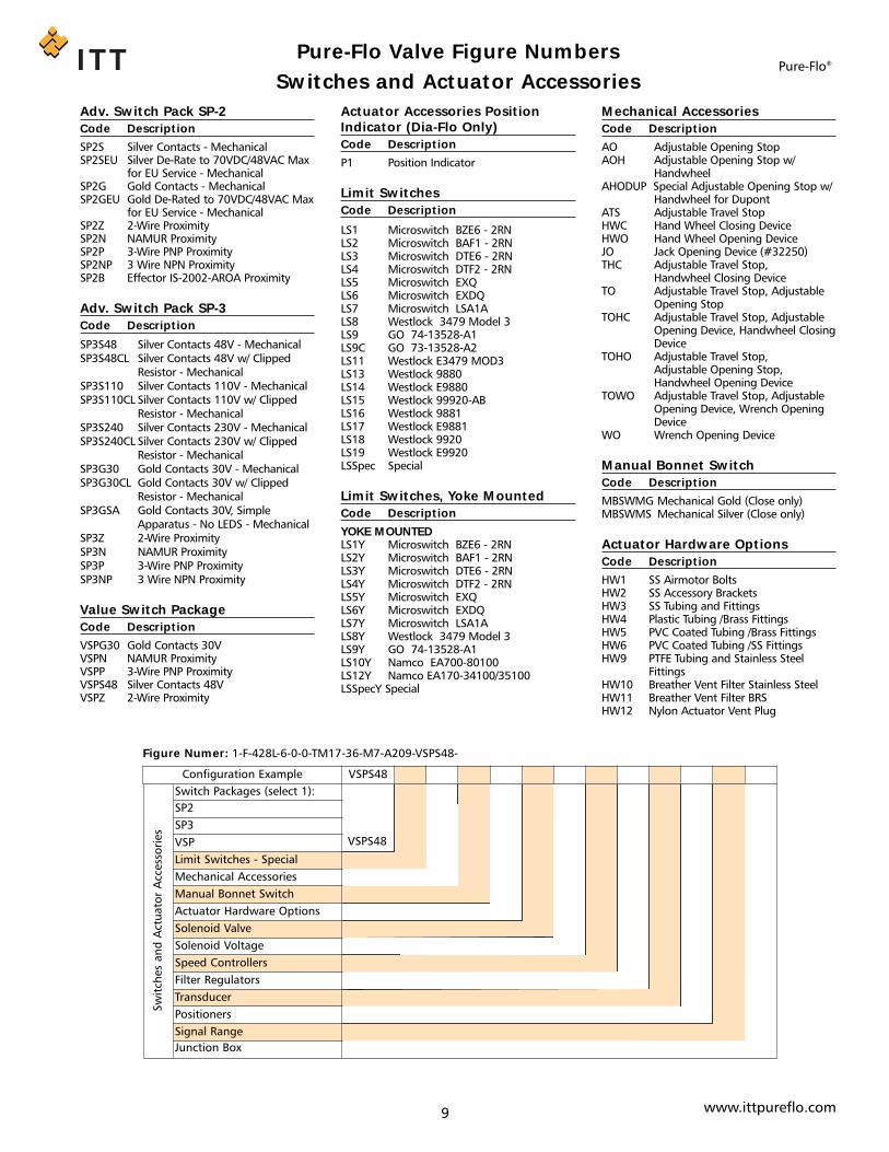
9 www.ittpureflo.com
Adv. Switch Pack SP-2
Code Description
SP2S Silver Contacts - MechanicalSP2SEU Silver De-Rate to 70VDC/48VAC Max
for EU Service - MechanicalSP2G Gold Contacts - MechanicalSP2GEU Gold De-Rated to 70VDC/48VAC Max
for EU Service - MechanicalSP2Z 2-Wire ProximitySP2N NAMUR ProximitySP2P 3-Wire PNP ProximitySP2NP 3 Wire NPN ProximitySP2B Effector IS-2002-AROA Proximity
Adv. Switch Pack SP-3
Code Description
SP3S48 Silver Contacts 48V - MechanicalSP3S48CL Silver Contacts 48V w/ Clipped
Resistor - MechanicalSP3S110 Silver Contacts 110V - MechanicalSP3S110CL Silver Contacts 110V w/ Clipped
Resistor - MechanicalSP3S240 Silver Contacts 230V - MechanicalSP3S240CL Silver Contacts 230V w/ Clipped
Resistor - MechanicalSP3G30 Gold Contacts 30V - MechanicalSP3G30CL Gold Contacts 30V w/ Clipped
Resistor - MechanicalSP3GSA Gold Contacts 30V, Simple
Apparatus - No LEDS - MechanicalSP3Z 2-Wire ProximitySP3N NAMUR ProximitySP3P 3-Wire PNP ProximitySP3NP 3 Wire NPN Proximity
Value Switch Package
Code Description
VSPG30 Gold Contacts 30VVSPN NAMUR ProximityVSPP 3-Wire PNP ProximityVSPS48 Silver Contacts 48VVSPZ 2-Wire Proximity
Actuator Accessories PositionIndicator (Dia-Flo Only)
Code Description
P1 Position Indicator
Limit Switches
Code Description
LS1 Microswitch BZE6 - 2RNLS2 Microswitch BAF1 - 2RNLS3 Microswitch DTE6 - 2RNLS4 Microswitch DTF2 - 2RNLS5 Microswitch EXQLS6 Microswitch EXDQLS7 Microswitch LSA1ALS8 Westlock 3479 Model 3LS9 GO 74-13528-A1LS9C GO 73-13528-A2LS11 Westlock E3479 MOD3LS13 Westlock 9880LS14 Westlock E9880LS15 Westlock 99920-ABLS16 Westlock 9881LS17 Westlock E9881LS18 Westlock 9920LS19 Westlock E9920LSSpec Special
Limit Switches, Yoke Mounted
Code Description
YOKE MOUNTEDLS1Y Microswitch BZE6 - 2RNLS2Y Microswitch BAF1 - 2RNLS3Y Microswitch DTE6 - 2RNLS4Y Microswitch DTF2 - 2RNLS5Y Microswitch EXQLS6Y Microswitch EXDQLS7Y Microswitch LSA1ALS8Y Westlock 3479 Model 3LS9Y GO 74-13528-A1LS10Y Namco EA700-80100LS12Y Namco EA170-34100/35100LSSpecY Special
Mechanical Accessories
Code Description
AO Adjustable Opening StopAOH Adjustable Opening Stop w/
HandwheelAHODUP Special Adjustable Opening Stop w/
Handwheel for DupontATS Adjustable Travel StopHWC Hand Wheel Closing DeviceHWO Hand Wheel Opening DeviceJO Jack Opening Device (#32250)THC Adjustable Travel Stop,
Handwheel Closing DeviceTO Adjustable Travel Stop, Adjustable
Opening StopTOHC Adjustable Travel Stop, Adjustable
Opening Device, Handwheel ClosingDevice
TOHO Adjustable Travel Stop, Adjustable Opening Stop,Handwheel Opening Device
TOWO Adjustable Travel Stop, AdjustableOpening Device, Wrench OpeningDevice
WO Wrench Opening Device
Manual Bonnet Switch
Code Description
MBSWMG Mechanical Gold (Close only)MBSWMS Mechanical Silver (Close only)
Actuator Hardware Options
Code Description
HW1 SS Airmotor BoltsHW2 SS Accessory BracketsHW3 SS Tubing and FittingsHW4 Plastic Tubing /Brass FittingsHW5 PVC Coated Tubing /Brass FittingsHW6 PVC Coated Tubing /SS FittingsHW9 PTFE Tubing and Stainless Steel
FittingsHW10 Breather Vent Filter Stainless SteelHW11 Breather Vent Filter BRSHW12 Nylon Actuator Vent Plug
Switches and Actuator AccessoriesPure-Flo®
Pure-Flo Valve Figure Numbers
Figure Numer: 1-F-428L-6-0-0-TM17-36-M7-A209-VSPS48-
Sw
itch
es
an
d A
ctu
ato
r A
ccess
ori
es
Switch Packages (select 1):
SP2
SP3
VSP
Limit Switches - Special
Mechanical Accessories
Manual Bonnet Switch
Actuator Hardware Options
Solenoid Valve
Solenoid Voltage
Speed Controllers
Filter Regulators
Transducer
Positioners
Signal Range
Junction Box
Configuration Example VSPS48
VSPS48

10 www.ittpureflo.com
Switches and Actuator Accessories (cont.)
Solenoid Valve
Code Description
SV1 Asco 8320G184SV2 Asco EF8320G184SV3 Asco 8345G1SV4 Asco EF8345G1SV8 Asco EF8320G202SV14 Burkert Series 6014SV15 Burkert Series 6015
Solenoid Voltage
Code Description
V1 120V / 60HZV2 24VDCV3 240V / 60HZVSpec Special
Speed Controllers
Code Description
SC Schrader 337-1001SC2 Whitey needle valve SS-1RMASCSpec Special
Filter Regulators
Code Description
FR1 Conoflow GFH60XTKEG3GFR1X2 Two Conoflow GFH60XTKEG3GFR2 Fisher 67FRFR2X2 Two Fisher 67FRFRSpec Special
Transducer
Code Description
TR1 Conoflow GT2108EDTR1630 Conoflow GT6108EDTRIPH Moore IPH/4-20MA/3-
15PSIG/20PSI/FR1/WDNSTRWS Watson Smith S3-4904-3XRTRSpec Special
Positioners
Code Description
PR1 Conoflow Model 31PR2 Conoflow Model 33PR3 Moore 73NFPR4 Moore 73 NBPR5 Moore 73 NRPR6 Conoflow P50PR7 Conoflow P51PR8 Conoflow P52PRSpec Special
Signal Ranges
Code Description
SR1 3-15 PSISR2 6-30 PSISR3 3-9 PSISR4 9-15 PSI
Junction Box
Code Description
JB Junction Box: StandardJBSpec Special
Pure-Flo®Pure-Flo Valve Figure Numbers
Figure Numer: 1-F-428L-6-0-0-TM17-36-M7-A209-VSPS48-
Sw
itch
es
an
d A
ctu
ato
r A
ccess
ori
es
Switch Packages (select 1):
SP2
SP3
VSP
Limit Switches - Special
Mechanical Accessories
Manual Bonnet Switch
Actuator Hardware Options
Solenoid Valve
Solenoid Voltage
Speed Controllers
Filter Regulators
Transducer
Positioners
Signal Range
Junction Box
Configuration Example VSPS48
VSPS48

11 www.ittpureflo.com
Special Service Preparation
Code Description
BAG Cleaned and BaggedDS Dual Scale (PSI/BAR) GaugesEU_SERVICE European Union ServiceNPC No Polishing CompoundOXY OxygenSIFREE Silicone Free PreparationSPEC Customer SpecialTOB TobaccoVAC Vacuum
Special Quality Documents
Code Description
SQDB CMTR (Body)SQD1 CMTR (body, tube, weld, weld rod)SQD2 C of C (seat & shell pressures)SQD3 C of C Profilometer Tape for each
bodySQDBIO C of C Diaphragm USP XXVIII Class
VI Biological ReactivitySQD5 C of C Body/Stud/Nut CMTR and C of
C to ASME Section VIIISQD6 C of C Tube CMTR, Tank Bottom
ValveSQD7 C of C Weld Rod CMTR, Tank Bottom
Valve
Service Preparation and Quality DocumentsPure-Flo®
Pure-Flo Valve Figure Numbers
Configuration Example SQDB
Special Service Preparation
Special Quality Documents SQDB
Figure Numer: 1-F-428L-6-0-0-TM17-36-M7-A209-VSPS48-SQDB

12 www.ittpureflo.com
Code Description
BODY TYPERTBV Radial Tank Bottom Valve8D Bio-Tek® Forged 1.4435 SSFD Forged 1.4435 SSBODY ENDS (BUTTWELD)423X 18 GA BT, Max Cutback , STD Length423XL 18 GA BT, Max Cutback , Non-STD
LG.428X 16 GA Max Cut Standard Length428XL 16 GA Max Cut Nonstandard Length429X 14 GA Max Cut Standard Length 433 ANSI Flanged489 RTBV, 90 Degree 16 GA Butt Weld490 RTBV, 90 Degree Tri-ClampSECOND END CODE (CLAMP)X23X 18 GA BT, Max Cutback STD LengthX23XL 18 GA BT, Max Cutback Non-STD LGX28X 16 GA BT, Max Cutback STD LengthX28L By 16 Gauge Extended Tangent BWX28XL 16 GA BT, Max Cutback Non-STD LGX29L By 14 Guage Extended Tangent BWXX29X 14 GA BT, Max Cutback STD LengthBONNETS, HANDWHEEL16 Standard Bio-Tek® Bonnet17 Sealed Bio-Tek® Bonnet902 Cast Iron Indicating902S Cast Iron Indicating - Sealed912 Stainless Steel (316) Indicating912S Stainless Steel (316) Indicating -
Sealed
932 Bronze Indicating932S Bronze Indicating - Sealed933 Bronze Indicating with Travel Stop
(1/2" - 4")933S Bronze Indicating with Travel Stop -
Sealed (1/2" - 4") 942 Double Iron Indicating942S Double IronIndicating - Sealed943 Double Iron Indicating with Travel
Stop943S Double Iron Indicating with Travel
Stop - Sealed950 Rising Handwheel with Travel Stop961 Plastic PAS Non-Indicating with
Travel StopWFI HOT LOCKOUT BONNET LBA 115VAC/60HZLBD 24VDCLBD1 24VDC with Position feedbackLBM 24VDC with Mech Switch OutputLBP 24VDC with Solid State Switch
OutputACTUATED BONNETS (BRONZE)33 Actuated33S Actuated - SealedOPTIONAL BONNET INTERNALSM11 316 Stainless Steel StemM12 PSU CapM13 Stainless Steel Compressor (Bio-Tek®)M14 Clear Cap
DIAPHRAGMSA Soft Natural Rubber (FDA)16 EPDM Compound 16 (FDA)B16 Biotek EPDM Compound 16 C HypalonH EPDM (FDA)NB NBTM PTEE (FDA)/Grade 16 BCTFM1700 TFM1700 PTFE (FDA)WB White Butyl (FDA)ADV. SWITCH PACK SP-2.5 SP5B Effector IS-2002-AROA ProximitySP5G Gold Contacts - MechanicalSP5GEU Gold De-Rated to 70VDC/48VAC Max
for EU Service - MechanicalSP5N NAMUR ProximitySP5NP 3 Wire NPN ProximitySP5P 3-Wire PNP ProximitySP5S Silver Contacts - MechanicalSP5SEU Silver De-Rated to 70VDC/48VAC Max
for EU Service - MechanicalSP5Z 2-Wire ProximitySOLENOID VALVE SV5 Burkert 300-C-1/16 -F-R-1/8-VOL
(Advantage)SV6 Burkert 311-C-5/64 -F-BR-1/8-VOL
(Advantage)SPECIAL SERVICE PREPARATIONCS Controlled Sulfur Body (0.005-
0.017%)
Obsolete Figure CodesPure-Flo®
Pure-Flo Valve Figure Numbers

13
Fabrication TypeCode Description
GMP GMPHSA Horizontal Sterile AccessSA Sterile AccessSPEC Special
Purge LocationCode Description
P1 Purge located closest to main valveend 1
P2 Purge located closest to main valveend 2
PB Purge located at both valve ends (P1and P2)
Purge Valve OrientationCode Description
B BackF FrontL LeftLL Left SpecialLR Left/Right SpecialR RightRL Right/Left SpecialRR Right Special
Valve Number for Fabrication Code Description
M Main Valve2 Second Valve3 Third Valve4 Fourth Valve5 Fifth Valve6 Sixth Valve7 Seventh Valve8 Eighth Valve9 Ninth Valve10 Tenth Valve
Sterile Access & GMP Fabrications
Note: See pages 5-11 for additional figure numbers.
www.ittpureflo.com
Pure-Flo®
Sterile Access Example
Sterile Access single valve fabrication with a 1.5" forged stainless steel main valve and a 0.5" forged purge tube closest to the second end. Themain valve has buttweld ends, 25 Ra polished interior, a 950 PBT manual bonnet and a modified PTFE diaphragm. The purge tube has a tri-clamp end.
SA1.5
F
Configuration Example SA 1.5 F 428L .5 X19 P2 6-0-0 TM17 950 SQD1
Sing
le V
alve
Fab
rica
tion
Fabrication Type Valve SizeBody TypeBody End CodeSecond End CodePurge Tube Size Purge Tube End CodePurge LocationPolish Selections (pg 5)Diaphragm Selection (pg 6)Bonnets & Bonnet Options (pg 7)Actuator Options (pg 8)Switches & Actuator Accessories (pg 9-10)Service Preparation & Quality Doc. (pg 11)
X19
Single Valve Fabrication Figure Number: SA-1.5-F-428L-.5-X19-P2-6-0-0-TM17-950-SQD1
428L
P2
6-0-0TM17
950
SQD1
.5
Pure-Flo Valve Figure Numbers
Sterile Access Orientations

Sterile Access & GMP Fabrications (cont.)Pure-Flo®
GMP Example
GMP two valve fabrication with a 2" forged stainless steel main valve and a 0.5" forged purge valve closest to the second end and facing tothe right. The main valve has Tri-Clamp ends, 25 Ra polished interior, a reverse acting advantage actuator with a 60lb spring, an SP-2 switchpack with silver mechanical contacts and a modified PTFE diaphragm. The secondary valve has 16 gauge ends, 25-inch polished interior, a PAShand-wheel operated bonnet with sanitary internals and a modified PTFE diaphragm.
GMP2
.5
Configuration Example GMP 2 2 .5
Fabr
icat
ion Fabrication Type
Two Valve FabricationMain Valve SizeSecond Valve Size
Fabrication Figure Number: GMP-2-2-.5
2
GMPM
419
2
Configuration Example GMP M 2 F 419 P2 R 6-0-0 TM17 36-M7 A216 SP2S SQD1
Mai
n Va
lve
Fabrication Type Valve NumberValve SizeBody TypeBody End CodeSecond End CodePurge LocationPurge Valve OrientationTube ExtensionPolish Selections (pg 5)Diaphragm Selection (pg 6)Bonnets & Bonnet Options (pg 7)Actuator Options (pg 8)Switches & Actuator Accessories (pg 9-10)Service Preparation & Quality Doc. (pg 11)
P2
Main Valve Figure Number: GMP-M-2-F-419-P2-R-6-0-0-TM17-36-M7-A216-SP2S-SQD1
F
R
6-0-0
TM17
36-M7A216
SP2SSQD1
GMP2
428L
.5
Configuration Example GMP 2 .5 F 428L R 6-0-0 TM17 963-M2 SQD1
Seco
nd V
alve
Fabrication Type Valve NumberValve SizeBody TypeBody End CodePurge Valve OrientationTube ExtensionPolish Selections (pg 5)Diaphragm Selection (pg 6)Bonnets & Bonnet Options (pg 7)Actuator Options (pg 8)Switches & Actuator Accessories (pg 9-10)Service Preparation & Quality Doc. (pg 11)
R
Second Valve Figure Number: GMP-2-.5-F-428L-R-6-0-0-TM17-963-M2-SQD1
F
6-0-0
TM17
963-M2
SQD1
14 www.ittpureflo.com
Pure-Flo Valve Figure Numbers
GMP Orientations

15
Zero Static Back-to-Back Sample Example
Zerostatic Block Body with a .75" wrought stainless steel main valve and a 1.5" tube. All three outlets are buttweld. Interior finish: RA 25, PBThand-wheel operated bonnet and a modified PTFE diaphragm. Bio-Tek sample valve with .75” Tri-clamp connection.
Fabrication Type
Code Description
ZSBBT Zero static Block Body TeeZSBBHV Zero static Block Body U-Bend:
Horizontal Tube - Vertical Valve ZSBBVV Zero static Block Body U-Bend:
Vertical Tube - Vertical Valve ZSBBS Zero static Back to Back Sample
ValveZSHH Zero static Horizontal Tube -
Horizontal ValveZSVH Zero static Vertical Tube - Horizontal
Valve
Body Type
Code Description
SVBT Sample Valve Bio-Tek® (R)SVPF Sample Valve Pure-Flo
Sample Valve Outlet Side
Code Description
R Ported on Right Side of Valve(Standard)
L Ported on Left Side of Valve
U Bend Tube Orientation (Optional)
Option Option Description
HV Horizontal U-Bend Tube with Vertical Valve Orientation
VV Vertical U-Bend Tube with VerticalValve Orientation
USPEC Special U-Bend Orientation
Body Ends
Code Description
419R .75” Tri-Clamp
Zero Static Fabrications
Note: See pages 5-11 for additional figure numbers.
www.ittpureflo.com
Pure-Flo®Pure-Flo Valve Figure Numbers
ZSBBS
.75
428
428
Configuration Example ZSBBS .75 428 1.5 428 .5 SVBT 419R R W 6-1-0 SQD1
Main
Valv
e
Fabrication Type
Valve Size
Body End Code
Zerostatic Tube Size
U-Bend Tube Orientation*
Zerostatic Tube End Code
Secondary Valve Size
Secondary Valve Type
Secondary Valve End Type
Secondary Outlet Orientation
Sample Outlet Side
Body Material
Polish Selections (pg 5)
Diaphragm Selection (pg 6 )
Service Preparation & Quality Doc. (pg 11)
.5
Main Valve Figure Number: ZSBBS-.75-428-1.5-428-.5-SVBT-419R-R-W-6-1-0-SQD1
1.5
SVBT
R
419R
W
6-1-0
SQD1
.75
N
950
Configuration Example .75 N TM17 950
Top
wo
rks
Valve Size
Body (Not Supplied)
Diaphragm (pg 6)
Bonnet (pg 7)
Options (pg 8-10)
Main Multiport Valve Topworks Figure Number: .75-N-TM17-950
TM17
Sample Multiport Valve Topworks Figure Number: .5-N-TM17-18
.5
N
18
Configuration Example .5 N TM17 18
Top
wo
rks
Valve Size
Body (Not Supplied)
Diaphragm (pg 6)
Bonnet (pg 7)
Options (pg 8-10)
TM17
* For a U-Bend Vertical Tube, enter VV. For Horizontal Tube, enter HV. All other figure numbers remain the same.
Zero Static Back-to-BackSample Valve
Zero Static Back-to-BackSample Valve with U-Bend

Zero Static Fabrications (cont.)Pure-Flo®
Pure-Flo Valve Figure Numbers
Zero Static Block Body U-Bend Example
Zerostatic Block Body Tee U-bend (Vertical Tube, Vertical Valve) with a 1" wrought stainless steel main valve anda 1.5" tube. The outlet of the valve body has Tri-Clamp ends. The tube has 1.5" buttweld 16 gauge ends. Interiorfinish: RA 25, PAS hand-wheel operated bonnet-sealed, sanitary internals and a PTFE diaphragm.
Zero Static Block Body Tee Example
ZSBBT with a 0.5" wrought stainless steel main valve and a 2" tube. All three outlets have tri-clamp ends. RA 25 ID, bothinterior and exterior electropolish, PAS hand-wheel operated bonnet, sanitary internals and EPDM diaphragm.
ZSBBT
.5
X19
W
Configuration Example ZSBBT .5 W 419 2 X19 6-1-3 17 963-M2 SQD1
Main
Valv
e
Fabrication Type
Valve Size
Body Type
Body End Code
Zerostatic Tube Size
Zerostatic Tube End Code
Zerostatic Tube Second End Code
Polish Selections (pg 5)
Diaphragm Selection (pg 6 )
Bonnets & Bonnet Options (pg 7-10)
Service Preparation & Quality Doc. (pg 11)
Valve Figure Number: ZSBBT-.5-W-419-2-X19-6-1-3-17-963-M2-SQD1
419
6-1-3
963-M2
17
SQD1
2
ZSBBVV
1
X28
W
Configuration Example ZSBBVV 1 W 419 1.5 X28 6-1-0 TM17 963S-M2 SQD1
Main
Valv
e
Fabrication Type
Valve Size
Body Type
Body End Code
Zerostatic Tube Size
Zerostatic Tube End Code
Zerostatic Tube Second End Code
Polish Selections (pg 5)
Diaphragm Selection (pg 6 )
Bonnets & Bonnet Options (pg 7-10)
Service Preparation & Quality Doc. (pg 11)
Valve Figure Number: ZSBBVV-1-W-419-1.5-X28-6-1-0-TM17-963S-M2-SQD1
419
6-1-0
963S-M2
TM17
SQD1
1.5
16 www.ittpureflo.com

Zero Static - Forged Bodies Example
Zerostatic with 1” forged triclamp main valve and 1.5” buttweld tube. Interior finish is 20 Ra withElectropolish ID and OD. PTFE diaphragm with EPDM backing cushion. PAS handwheel operated bon-net. Purge valve oriented on right side.
ZSHH
1
X28
F
Configuration Example ZSHH 1 F 419 1.5 X28 R 8-0-3 TM17 963-M2 SQD1
Main
Valv
e
Fabrication Type
Valve Size
Body Type
Body End Code
Zerostatic Tube Size
Zerostatic Tube End Code
Zerostatic Tube Second End Code
Purge Valve Orientation
Polish Selections (pg 5)
Diaphragm Selection (pg 6 )
Bonnets & Bonnet Options (pg 7-10)
Service Preparation & Quality Doc. (pg 11)
Valve Figure Number: ZSHH-1-F-419-1.5-X28-R-8-0-3-TM17-963-M2-SQD1
419
8-0-3
963-M2
TM17
SQD1
1.5
R
Zero Static Fabrications (cont.)Pure-Flo®
Pure-Flo Valve Figure Numbers
17 www.ittpureflo.com
Zero-Static Orientations

Multiport ValvesPure-Flo®
Pure-Flo Valve Figure Numbers
Type of Valve
Option Description
DV2W Divert Valve 2-wayDV3W Divert Valve 3-wayDV4W Divert Valve 4-wayDV5W Divert Valve 5-wayDV6W Divert Valve 6-wayCHRO ChromatographyCHRONBP Chromatography Valve without
BypassCRO Cross over ValveCROD Cross over Valve with Drain AngleSB1 Sterile Barrier Valve Option 1SB2 Sterile Barrier Valve Option 2DIDO Double Inlet Double Outlet
Diverter ValveBP Pure-Flo Valve with Bypass OptionISG Integral Sterile Access GMP ValveVSPEC Special Valve Type
Type
Option Description
BT Bio-Tek®
PF Pure-Flo
Outlet Option
Option Description
Refer to the drawing that correspondsto the type chosen1 Outlet Configuration 12 Outlet Configuration 23 Outlet Configuration 34 Outlet Configuration 45 Outlet Configuration 56 Outlet Configuration 67 Outlet Configuration 78 Outlet Configuration 8OSPEC Special Outlet Configuration
Material
Option Description
W Wrought 316LWA Wrought AL6XNWC2 Wrought C-22WC6 Wrought C-276WT Wrought TitaniumBSPEC Special Material
Flow Through (Optional)
Option Description
DVFT Divert Flow-Through
Note: See pages 5-11 for additional figure numbers.
Divert Example
2-Way Divert Valve with a 1.5" wrought stainless steel body. The inlet and outlets have Tri-Clamp ends. The outlet is Option 2. The Interior fin-ish: RA 25. Fail close Advantage® Actuator 60# spring. Modified PTFE diaphragm.
1.5
N
950
Configuration Example 1.5 N TM17 31-M7 A216
Top
wo
rks
Valve Size
Body (Not Supplied)
Diaphragm (pg 6)
Bonnet (pg 7)
Options (pg 8-10)
Main Valve Topworks Figure Number: 1.5-N-TM17-31-M7-A216
TM17
DV2W
1.5
W
Configuration Example DV2W 1.5 2 419 W 6-1-0 SQD1
Main
Valv
e
Fabrication Type
Valve Size
Body Type (.5” only)
Divert Outlet Option
Divert End Connections
Body Material
Polish Selections (pg 5)
Service Preparation & Quality Doc. (pg 11)
Valve Figure Number: DV2W-1.5-2-419-W-6-1-0-SQD1
2
6-1-0
SQD1
419
A216
1.5
N
950
Configuration Example 1.5 N TM17 31-M7 A216
Top
wo
rks
Valve Size
Body (Not Supplied)
Diaphragm (pg 6)
Bonnet (pg 7)
Options (pg 8-10)
Secondary Valve Topworks Figure Number: 1.5-N-TM17-31-M7-A216
TM17
A216
18 www.ittpureflo.com
Topworks
Topworks for Multiport and Specialty Valves are configured separately from the bodies;they do not appear in the valve figure number but are listed after the body configura-tion. Once the Multiport Valve has been described, the Topworks configuration willappear.

19
Multiport Valves (cont.)
Option 1 Option 2
Option 3 Option 4
Option 5 Option 6
Option 7 Option 8
End Connection Options
www.ittpureflo.com
Pure-Flo®Pure-Flo Valve Figure Numbers
Integral Sterile Access GMP Example
ISG Valve with a 2" wrought stainless steel body. Secondary valve is 1.5”, ported on right side of valve. The outlet is Option 5. The Interior fin-ish: RA 20. Fail close Advantage® Actuator 60# spring. Modified PTFE diaphragm.
ISG
2
1.5
Configuration Example ISG 2 5 1.5 R W 8-1-0 SQD1
Main
Valv
e
Fabrication Type
Valve Size
Body Type (.5” only)
Outlet Option
Second Valve Size
Valve Type (.5” only)
Sample Outlet Side
Body Material
Polish Selections (pg 5)
Service Preparation & Quality Doc. (pg 11)
R
Main Valve Figure Number: ISG-2-5-1.5-R-W-8-1-4-SQD1
5
W
8-1-0
SQD1
2
N
31-M7
Configuration Example 2 N TM17 31-M7 A216
Top
wo
rks
Valve Size
Body (Not Supplied)
Diaphragm (pg 6)
Bonnet (pg 7)
Options (pg 8-10)
Main Valve Topworks Figure Number: 2-N-TM17-31-M7-A216
TM17
A216
1.5
N
31-M7
Configuration Example 1.5 N TM17 31-M7 A216
Top
wo
rks
Valve Size
Body (Not Supplied)
Diaphragm (pg 6)
Bonnet (pg 7)
Options (pg 8-10)
Secondary Valve Topworks Figure Number: 1.5-N-TM17-31-M7-A216
TM17
A216
Topworks
Topworks for Multiport and Specialty Valves are configured separately from thebodies; they do not appear in the valve figure number but are listed after thebody configuration. Once the Multiport Valve has been described, the Topworksconfiguration will appear.

20
Terms and Conditions of SaleCONDITIONS and TERMS of SALE of ITT INDUSTRIAL & BIOPHARM GROUP (IBG)(hereinafter referred to as Company)
www.ittpureflo.com
WARRANTY - Company warrants title to the product(s) and,except as noted with respect to items not of Company’smanufacturer, also warrants the product(s) on date of ship-ment to Purchaser, to be of the kind and quality describedherein, and free of defects in workmanship and material.This warranty is expressly in lieu of all other war-ranties, including but not limited to implied war-ranties of merchantability and fitness, and consti-tutes the only warranty of the company with respectto the product(s).
If within one year from date of initial operation, but notmore than eighteen months from date of shipment byCompany of any item of product(s), Purchaser discovers thatsuch item was not as warranted above and promptly notifiesCompany in writing thereof. Company shall remedy suchnonconformance by, at Company’s option, adjustment orrepair or replacement of the item and any affected part ofthe product(s). Purchaser shall assume all responsibility andexpense for removal, reinstallation, and freight in connectionwith the foregoing remedies. The same obligations and con-ditions shall extend to replacement parts furnished byCompany hereunder. Company shall have the right of dispos-al of parts replaced by it. Purchaser agrees to notifyCompany, in writing, of any apparent defects in design,material or workmanship, prior to performing any correctiveaction back chargeable to the Company. Purchaser shall pro-vide a detailed estimate of the material, labor costs associat-ed with proposed remedy for expeditious review andapproval by the Company.
Seller neither assumes, nor authorizes any person to assume forit, any other obligation in connection with the sale of its engi-neering designs or products. This warranty shall not apply toany products or parts of products which (a) have been repairedor altered outside of Seller’s factories or authorized service cen-ters, in any manner; or (b) have been subjected to misuse, neg-ligence or accidents; or (c) have been used in a manner con-trary to Seller’s instructions or recommendations. Seller shallnot be responsible for design errors due to inaccurate orincomplete information supplied by Buyer or its representa-tives.Any separately listed item of the product(s) which isnot manufactured by the company is not warrantedby the company and shall be covered only by the expresswarranty, if any, of the manufacturer thereof.
This states purchaser’s exclusive remedy againstcompany and its suppliers relating to the product(s),whether in contract or in tort or under any otherlegal theory, and whether arising out of warranties,representations, instructions, installations or defectsfrom any cause. Company and its suppliers shall have noobligation as to any product which has been improperlystored or handled, or which has not been operated or main-tained according to instructions in Company or supplier fur-nished manuals.
LIMITATION OF LIABILITY - Neither Company nor its suppli-ers shall be liable, whether in contract or in tort or under anyother legal theory, for loss of use, revenue or profit, or forcost of capital or of substitute use or performance, or forincidental, indirect, or special or consequential damages, orfor any other loss or cost of similar type, or for claims byPurchaser for damages of Purchaser’s customers. Likewise,Company shall not, under any circumstances, be liable forthe fault, negligence, or wrongful acts of Purchaser orPurchaser’s employees, or Purchaser’s other contractors orsuppliers.
In no event shall company be liable in excess of thesales price of the part(s) or product found defective.
GENERAL - (a) Company will comply with all laws applicableto Company. Compliance with OSHA or similar federal, stateor local laws during any operation or use of the product(s) isthe sole responsibility of Purchaser. (b) The laws of the Stateof New York shall govern the validity, interpretation andenforcement of any contract of which these provisions are apart, without giving effect to any rules governing the conflictof laws. (c) This document and any other documents specifi-cally referred to as being a part hereof, constitute the entirecontract on the subject mater, and it shall not be modifiedexcept in writing signed by both parties, Unless otherwisespecified, any reference to Purchaser’s order is for identifica-tion only. Assignment may be made only with written con-sent of both parties.
ACCEPTANCE - The determination of compliance with per-formance guarantees will be based on results of factory testsunder controlled conditions with calibrated instruments andtested per standards of the Hydraulic Institute, ISO stan-dards, API standards, or other nationally recognized accredi-tation standards mutually acceptable to Company andPurchaser.
SHIPMENT - The term “shipment” means delivery to the ini-tial carrier in accordance with the delivery terms of thisorder. Company may make partial shipments. Company shallselect method of transportation and route, unless terms aref.o.b. point of shipment and Purchaser specifies the methodand route and is to pay the freight costs in addition to theprice, When terms are f.o.b. destination or freight allowed todestination, “destination” means common carrier deliverypoint (within the continental United States, excluding Alaska)nearest the destination. For movement outside the UnitedStates, company shall arrange for inland carriage to port ofexit and shall cooperate with Purchaser’s agents in makingnecessary arrangements for overseas carriage and preparingnecessary documents.
SPECIAL SHIPPING DEVICES - On shipments to a destina-tion in the continental United States or Canada, Companyhas the right to add to the invoice, as a separate item, thevalue of any special shipping device (barrel, reel, tarpaulin,cradle, crib and the like) used to contain or protect the prod-uct(s) invoiced, while in transit. Full credit will be given onthe return to Company of the device in a reusable condition,f.o.b. destination, freight prepaid.
DELAYS - If Company suffers delay in performance due toany cause beyond its control, including but not limited to actof God, war, act or failure to act of government, act or omis-sion of Purchaser, fire, flood, strike or labor troubles, sabo-tage, or delay in obtaining from others suitable services,materials, components, equipment or transportation, thetime of performance shall be extended a period of timeequal to the period of the delay and its consequences.Company will give to Purchaser notice in writing within areasonable time after Company becomes aware of any suchdelay.
NONCANCELLATION - Purchaser may not cancel or termi-nate for convenience, or direct suspension of manufacture,except on mutually acceptable terms.
STORAGE - Any item of the product(s) on which manufac-ture or shipment is delayed by causes within Purchaser’s con-trol, or by causes which affect Purchaser’s ability to receivethe product(s), may be placed in storage by Company forPurchaser’s account and risk.
Pure-Flo®Pure-Flo Valve Figure Numbers

Terms and Conditions of Sale
21 www.ittpureflo.com
TITLE AND INSURANCE - Title to the product(s) and risk ofloss or damage shall pass to Purchaser at the f.o.b. point,except that a security interest in the product(s) and proceedsand any replacement shall remain in Company, regardless ofmode of attachment to realty or other property, until the fullprice has been paid in cash. Purchaser agrees to do all actsnecessary to perfect and maintain said security interest, andto protect Company’s interest by adequately insuring theproduct(s) against loss or damage from any external causewith Company named as insured or co-insured.
INSPECTIONS / EXPEDITING - The Company wishes to clari-fy that it will have to restrict access to agreed upon reason-able times and only for the purpose of conducting thoseinspections agreed upon. We request 72 hours notice priorto each visit. We request notification prior to visits to oursubcontractors and require that we accompanyinspectors/expeditors on their visit(s).
TERMS OF PAYMENT - Unless otherwise stated all paymentsshall be Letter of Credit or Net Thirty (30) Days and in UnitedStates dollars, and a pro rata payment shall become due aseach shipment is made. If shipment is delayed by Purchaser,date of readiness for shipment shall be deemed to be date ofshipment for payment purposes. If at any time in Company’sjudgment Purchaser may be or may become unable orunwilling to meet the terms specified, Company may requiresatisfactory assurances or full or partial payment as a condi-tion to commencing or continuing manufacture or makingshipment; and may, if shipment has been made, recover theproduct(s) from the carrier, pending receipt of such assur-ances.
TAXES - Any applicable duties or sales, use, excise, valueadded or similar taxes will be added to the price andinvoiced separately (unless acceptable exemption certificateis furnished).
PRODUCT RETURN - Products can be returned for creditonly after receiving Company’s authorization and shippinginstructions. Consignor’s name and address must be plainlywritten on the shipping tag.
PATENTS - Company shall pay costs and damages finallyawarded in any suit against Purchaser or its vendees to theextent based upon a finding that the design or constructionof the product(s) as furnished infringes a United Statespatent (except infringement occurring as a result of incorpo-rating a design or modification at Purchaser’s request) pro-vided that Purchaser promptly notifies Company of anycharge of such infringement, and Company is given the rightat its expense to settle such charge and to defend or controlthe defense of any suit based upon such charge. This para-graph sets forth company’s exclusive liability withrespect to patents.
BUYER DATA - Timely performance is contingent upon thePurchaser supplying to the Company, when needed, allrequired technical information, including drawing approval,and all required commercial documentation.
NUCLEAR - Purchaser represents and warrants that theproduct(s) covered by this contract shall not be used in or inconnection with a nuclear facility or application.
PRICES - The prices stated herein will remain firm for theperiod up to the stated date of shipment providing the ship-ment is not delayed by the customer. If shipment is delayedby the customer beyond the shipment date quoted herein,the prices will be based on the prices in effect at time ofshipment, including storage and material handling costs. Inno event shall the adjusted price be less than the originalorder price, including change orders. Prices are F.O.B.Shipping Point, unless otherwise specified. When priceincludes transportation and other charges pertaining to theshipment of goods, any increase in transportation rates and
other charges will be for the account of the purchaser. Therewill be an extra charge for any test other than that whichmay be normally run by the Company, or for any test per-formed to suit the convenience of the purchaser.
CONTROLLING PROVISIONS - These terms and conditionsshall control with respect to any purchase order or sale ofthe Company’s products. No waiver, alteration or modifica-tion of these terms and conditions whether on Purchaser’spurchase order or otherwise shall be valid unless the waiver,alteration or modification is specifically accepted in writingand signed by an authorized representative the of Company.
EXPORT - If this transaction involves export, the followingadditional terms and conditions shall apply:
• Compliance is required for all applicable US export laws,and the export laws of the country from where the prod-uct is exported.
• PACKING - when packing is in IBG scope of supply, equip-ment will be packed, boxed or crated in accordance withthe Company’s standard commercial practice, for underdeck export shipment, unless otherwise agreed.
• LETTER OF CREDIT - Unless otherwise specified in writ-ing, payment shall be made by irrevocable letter of creditin form acceptable to Company, confirmed by a majorUSA bank, acceptable to the company and providing forpayment in full in United States dollars against presenta-tion of United States inland shipping documents andinvoices, such letter of credit to be established prior tocompany’s acceptance of the order. The letter of creditshall also provide that in the event Company is, for anyreason beyond its control, prevented from making ship-ment from Company’s factory or delivery at the port ofembarkation, a certificate of manufacture of the whole orany part of the goods shall constitute delivery of suchwhole or any part of the goods and payment in full of anyand all drafts drawn against the letter of credit for thegoods so “delivered” shall be made upon presentation ofsuch certificates of manufacture in lieu of United Statesinland shipping documents. In the event that Company isprevented by law, or otherwise, from making shipmentfrom Company’s factory or delivery at port of embarkationof the goods or any part thereof, on completion of manu-facture, Company reserved the right to place the goods instorage for the Purchaser’s account and risk. Any chargesincurred in this connection will be for the account of thePurchaser at cost and will be payable upon demand. Inregions where Letters of Credit are not available, suretybonds will be utilized in lieu of the bank guarantee.
• COMPANY AS AGENT - If Company makes or arrangesfor ocean shipment, Company shall act as agent for thePurchaser and reserves the right to procure full insurancecoverage, including war risk insurance, at the expense ofthe Purchaser. All expenses incurred in this connection willbe payable upon demand to the Company. If Company asagent applies for or secures manufacturing, financing,exporting or other licenses required by the United StatesGovernment, or any department thereof, Company shallmake such applications or secure such licenses solely asgent for the purchaser, and assumes no responsibilitytherefore.
Pure-Flo®Pure-Flo Valve Figure Numbers

For more information, please contact:
Pure-Flo Headquarters33 Centerville RoadLancaster, PA 17603-2064 USAPhone +1 (800) 787-3561Phone +1 (717) 509-2200Fax +1 (800) 239-9402
Website: www.ittpureflo.comE-mail: [email protected]
Valve Office Locations:
Pure-Flo110-B West CochranSimi Valley, CA 93065 USAPhone +1 (800) 926-8884Phone +1 (805) 520-7200Fax +1 (805) 520-7205
Pure-FloRichards StreetKirkham, LancashirePR4 2HU, EnglandPhone +44-1772-682696Fax +44-1772-686006
© 2006 ITT CorporationIndustrial & BioPharm Group
8H.POD
22
PFORD-06


