61
AM General Corporation MILITARY HMMWV For All M998 Series Vehicles Use of Technical Manuals 5715587

AM General Corporation
MILITARYHMMWV
For All M998 Series Vehicles
Use of Technical Manuals
5715587

AM General CorporationTraining DepartmentP.O. Box 728408 South Byrkit StreetMishawaka, IN 46546-0728 USAPhone: (219) 258-6624Fax: (219) 254-2260
Copyright
®
1999, AM General Corporation
This publication, or parts thereof, may not be reproduced in any form, by any method, for any purpose without written permission from AM General Corporation.

Page 1
Section 1HOW TO USE TECHNICAL MANUALS
1.
GENERAL FEATURES
: The TM is the fundamental means by which the army commu-nicates to soldiers the requirements and procedures necessary to perform equipment operations and maintenance. This program is designed to give you a basic understand-ing of the army technical manual system to enable you to get the maximum service life out of your equipment.
* INSTRUCTOR GO TO SLIDE #2

AM General Corporation
Page 2
2.
YOUR TM
is the best source available for providing the listed information and data criti-cal to vehicle maintenance.
• General Information, Description, and Data ............................ (Chapter 1)................... TM-2320-XXX-20-1
• Troubleshooting ...................................... (Chapter 2, Sec. IV) ..... TM-2320-XXX-20-1
• Detailed Maintenance Procedures ......... Chapter 3-12)............... TM-2320-XXX-20-2
• General Maintenance Instructions.......... Chapter 2, Sec. II & III) TM-2320-XXX-20-2
• Maintenance Allocation .......................... (Appendix B) ................ TM-2320-XXX-20-3
• Illustrated List of Manufactured Items..... (Appendix D)................ TM-2320-XXX-20-3
• Torque Limits .......................................... (Appendix E) ................ TM-2320-XXX-20-3
• Mandatory Replacement Parts............... (Appendix G)................ TM-2320-XXX-20-3
• Metric Conversion Chart......................... (Back Cover) ................ Most TM’s
* AFTER DISCUSSION, GO TO SLIDE #3.

Page 3
3.
FIRST
, you need to know which technical manual to use for your assigned task and for your individual maintenance skill level.
• Discuss “Which Publication to Use Chart.
* AFTER DISCUSSION, GO TO SLIDE #4.
TM 9 - 2320 - 280 - 34 - P - 3
TECH
NIC
AL PUBLIC
ATION
RESPO
NSIBLE AG
ENC
Y
CLASSIFIC
ATION
SPECIFIC
VEHIC
LE TYPE
USER
LEVELPAR
TS
VOLU
ME N
UM
BER
TB SC TM
SB LO FM
ORD 9ENG 5SIGNAL 11QM 8CHEM 2TRANS 55
WHEEL-2320TRACKTRAILERRADIOWEAPONS
JEEP -2182.5 TON -3615 TON -260HMMWV-280
-10 -20-24 -34-35
AUTOTOOLSKITS
VOLUMENUMBERIN SERIES
TB – TECHNICAL BULLETINSC – SUPPLY CATALOGTM – TECHNICAL MANUALSB – SUPPLY BULLETINLO – LUBRICATION ORDERFM – FIELD MANUAL

AM General Corporation
Page 4
4.
ASSIGNED TASK:
Unit Maintenance has reported that a HMMWV has
loss of cool-ant
in the cooling system. The vehicle has been assigned to you for repair.
Troubleshooting Steps
• Look at the cover of the manual. You will see chapter titles listed from top to bottom on the right-hand side.
• Look for “General Maintenance” in the chapter list on the cover. This is where trouble shooting information is located.
* AFTER DISCUSSION GO TO SLIDE #5.

Page 5
5.
Go to page 2-2 which is the
“Troubleshooting Symptom Index”
.Look down the list until you find “Engine”. Beneath that heading you will find the symp-toms noted by unit maintenance:
(Loss of Coolant Item #11).
* AFTER DISCUSSION, GO TO SLIDE #6.
AM General Corporation
Page 6
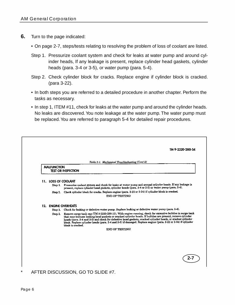
6.
Turn to the page indicated:
• On page 2-7, steps/tests relating to resolving the problem of loss of coolant are listed.
Step 1. Pressurize coolant system and check for leaks at water pump and around cyl-inder heads, If any leakage is present, replace cylinder head gaskets, cylinderheads (para. 3-4 or 3-5), or water pump (para. 5-4).
Step 2. Check cylinder block for cracks. Replace engine if cylinder block is cracked.(para 3-22).
• In both steps you are referred to a detailed procedure in another chapter. Perform the tasks as necessary.
• In step 1, ITEM #11, check for leaks at the water pump and around the cylinder heads. No leaks are discovered. You note leakage at the water pump. The water pump must be replaced. You are referred to paragraph 5-4 for detailed repair procedures.
* AFTER DISCUSSION, GO TO SLIDE #7.
2-7

Page 7
7.
A. Go to paragraph 5-4.
B. After reporting the results of your troubleshooting efforts to your supervisor, hedecides the most expedient means of repairing the vehicle would be to replace the waterpump.C. In paragraph 5-4 you will find the detailed maintenance procedure for
“water pumpand adapter plate replacement.”
TURN THE PAGE AND
CONTINUE
WITH SLIDE #7.
AM General Corporation
Page 8
Detailed Maintenance Procedures:
D. Detailed procedures include everything you must do to accomplish a basic maintenancetask.
E. Before beginning the task, look through the procedure.
F. The basic headings listed under “Initial Setup” outline task conditions, materials, specialtools, manpower requirements, and special conditions. The headings are as follows.
•
Applicable
Models
are any models that require a particular maintenance task. If a maintenance task covers all models, then this heading will not be used.
•
Test
Equipment
is test equipment needed to complete a task. If test equipment is not required, this heading will not be used.
•
Special
Tools
are those special tools needed to complete a maintenance task. If spe-cial tools are not required, this heading will not be used.
•
Tools
are the tools and equipment needed to complete a maintenance task.
•
Materials/Parts
is a heading that lists only mandatory replacement parts or materials.
•
Personnel Required
is the number of personnel required to perform a task. If only one mechanic is required, this heading will not be used.
•
Manual References
are those TMs needed to complete the task.
•
Equipment Conditions
are conditions which must exist before starting the task.
•
General Safety Instructions
are a summary of all warnings for the maintenance task if any apply.
•
Maintenance Level
identifies maintenance level required to perform a task.
G. A
Step-By-Step
maintenance procedure follows the “initial setup” and gives detailedinstructions for the procedure.
* AFTER DISCUSSION, GO TO SLIDE #8

Page 9
8.
Warnings
,
Cautions
and
Notes
provide supplemental information:
•
Warnings
—indicate conditions, practices or procedures which must be observed to avoid personnel injury, loss of life, or long-term health problems.
•
Cautions
—indicate conditions, practices, or procedures which must be observed to avoid damage to equipment or destruction of equipment.
•
Notes
—contain information essential to task performance.
* AFTER DISCUSSION, GO TO SLIDE #9.

AM General Corporation
Page 10
9.
At the end of a procedure, “
Follow-on-Tasks
” will list those additional tasks that must be performed to complete the procedure. The follow-on-tasks for water pump replace-ment are:
• Install water pump pulley . . . . . . . . . . . . . . . . . . . . . . . . . . . . . . . . TM 9-2320-280-20
• Install inlet Hose . . . . . . . . . . . . . . . . . . . . . . . . . . . . . . . . . . . . . . . TM 9-2320-280-20
• Install engine oil filler tube . . . . . . . . . . . . . . . . . . . . . . . . . . . . . . . TM 9-2320-280-20
• Install thermostat bypass hose. . . . . . . . . . . . . . . . . . . . . . . . . . . . TM 9-2320-280-20
* AFTER DISCUSSION, GO TO SLIDE #10.

Page 11
10.
Modular Text
: Both pages of test and illustrations are to be used together. This manual was designed so that the two pages would be visible at once, making part identification and procedure sequence easy to follow.
* AFTER DISCUSSION, GO TO SLIDE #11.

AM General Corporation
Page 12
11.
Illustrations
: An exploded diagram of the component shows part locations, attach-ments, and relationships. Cutaway views show the location and orientation of screws and attachemtns.
* AFTER DISCUSSION, GO TO SLIDE #12
Page 13
12.
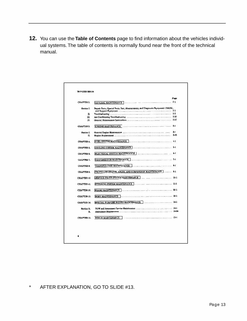
You can use the
Table of Contents
page to find information about the vehicles individ-ual systems. The table of contents is normally found near the front of the technical manual.
* AFTER EXPLANATION, GO TO SLIDE #13.

AM General Corporation
Page 14
13.
The
Index
gives you an individual breakdown for quick accessing of parts and informa-tion. The index is normally found near the back of the technical manual.
* AFTER EXPLANATION, GO TO SLIDE #14.

Page 15
14.
References
: A thorough reference file of associated publications, forms and field man-uals for use with this vehicle. This reference is located in Appendix A.
* AFTER EXPLANATION GO TO SLIDE #15

AM General Corporation
Page 16
15.
Expendable/Durable Supplies
: A comprehensive list of expendable supplies and material to be used in performance of maintenance tasks.
* AFTER EXPLANATION GO TO SLIDE #16

Page 17
16.
Manufacturing Instructions
is a fully illustrated list of items to be fabricated for use in performing maintenance tasks on the HMMWV.
* AFTER EXPLANATION GO TO SLIDE #17.

AM General Corporation
Page 18
17.
Torque Limits
: A quick reference chart for determining torque specifications on bolts.
* AFTER EXPLANATION GO TO SLIDE #18.

Page 19
18.
Metric System
is a quick and accurate conversion chart for metric system and equiva-lents.
* AFTER EXPLANATION GO TO SLIDE #19.

AM General Corporation
Page 20
19.
Operator
PMCS
(Preventive Maintenance Checks and Services).Discuss:
• Before
• Fluid Leak
• Not mission capable
• Class III leaks
* GO TO SLIDE #20.

Page 21
20.
Operator PMCSDiscuss:
• During
• Grabbing Brakes.
* GO TO SLIDE #21

AM General Corporation
Page 22
21.
Operator PMCSDiscuss:
• After
• Tires
• Not Mission Capable
* GO TO SLIDE #22.

Page 23
22.
Operator PMCS:Discuss:
• Weekly
• Tires
* GO TO SLIDE #23.

AM General Corporation
Page 24
23.
Operator Lubrication:Discuss:
• Monthly
• Tailgate
* GO TO SLIDE #24

Page 25
24.
Operator LubricationDiscuss
• Intervals 3,000 miles (4,827 km)
• Lubricants Six Months (Semiannually)
• Local View (LV–A)
• Notes
* GO TO SLIDE #25.

AM General Corporation
Page 26
25.
Operator Lubrication:Discuss:
• Localized Lubrication Points
* GO TO SLIDE #26.

Page 27
26.
Operator Lubrication:Discuss:
• Lubrication Notes
* GO TO SLIDE #27.

AM General Corporation
Page 28
27.
Operator Troubleshooting:
The troubleshooting table contains instructions that will help the operator identify andcorrect simple vehicle malfunctions. The table also helps the operator identify majormechanical difficulties that must be referred to unit maintenance. The listing of possiblemalfunctions come under major vehicle headings. They are:
• Engine
• Heating System
• Transmission
• Transfer Case
• Brakes
• Wheels and Tires
• Steering
• Winch
• Special Purpose Bodies
* AFTER DISCUSSION GO TO SLIDE #28.

Page 29
28.
Operator Troubleshooting Table:
Table 3-1 Lists the common malfunctions which you may find during the operation ormaintenance of the HMMWV or its components. You should perform the tasks and cor-rective actions in the order listed.
* AFTER DISCUSSION, GO TO SLIDE #29

AM General Corporation
Page 30
29.
Unit Mechanics PMCS:
The best way to maintain vehicles covered by this manual is to inspect them on a regularbasis so minor faults can be detected and corrected before they result in serious dam-age, failure or injury.
Intervals:
1.
Semiannually (s)
: Every six months or 3,000 miles (4,827 km), which ever comesfirst.
2.
Annually (A)
: Every twelve months or 6,000 miles (9,654 km) whichever comes first.
3. Biennially (B): Every 24 months or 12,000 miles (19,308 km), whichever comes first.
* GO TO SLIDE #30.

Page 31
30. Preventive Maintenance Checks and Services (PMCS):Discuss:
• Interval
• Prior to road test
• Road test procedures
* AFTER DISCUSSION GO TO SLIDE #31.

AM General Corporation
Page 32
31. PMCS (Unit Level):Discuss:
• E, F, B, Procedures
• Cover “B” in detail
• Not mission capable
* AFTER DISCUSSION GO TO SLIDE #32.

Page 33
32. PMCS (Unit Level):Discuss
• C and D
• Not mission capable
* AFTER DISCUSSION, GOT O SLIDE #33.

AM General Corporation
Page 34
33. Lubrication Table:Discuss:
• Usage
• Lubricants
• Capacities
* AFTER DISCUSSION FO TO SLIDE #34.
15W40 6.5L

Page 35
34. Troubleshooting Index:Discuss:
• General Systems
* AFTER DISCUSSION, GO TO SLIDE #35.

AM General Corporation
Page 36
35. Troubleshooting Guide:
There are 16 foldouts that are supplied with this manual, one for each of the system leveltests. Take the foldouts and place them after the last page of diagnostics at the end ofeach paragraph. That way, the foldout for each test procedure will be with the diagnosticsfor that test.
System Level Tests Paragraph Foldout Number
Fuel 2-22 FO-1
Air Intake/Exhaust 2-23 FO-2
Compression/Mechanical 2-24 FO-3
Engine Cooling 2-25 FO-4
Engine Lubrication 2-26 FO-5
Alternator 2-27 FO-6
Battery Circuit 2-28 FO-7
Starter Circuit 2-29 FO-8
Glowplugs 2-30 FO-9
Instruments 2-31 FO-10
Lights 2-32 FO-11
Transmission 2-33 FO-12
Brakes 2-34 FO-13
Steering 2-35 FO-14
Drivetrain 2-36 FO-15
DCA Troubleshooting 2-37 FO-16
* AFTER DISCUSSION, GO TO SLIDE #36.

Page 37
36. Troubleshooting Chart:Discuss:
• All callouts
• Note that all diagnostic and flowcharts are on the left hand page, while supporting in-formation, help, test instructions and vehicle operation on the right.
* AFTER DISCUSSION GO TO SLIDE #37.

AM General Corporation
Page 38
37. Troubleshooting Chart:Discuss:
• Complete Chart
* AFTER DISCUSSION GO TO SLIDE #38.

Page 39
38. Troubleshooting Chart:Discuss:
• Complete Chart
* AFTER DISCUSSION, GO TO SLIDE #39.
AM General Corporation
Page 40
39. Troubleshooting Chart:Discuss:
• Complete Chart
* AFTER DISCUSSION, GO TO SLIDE #40.
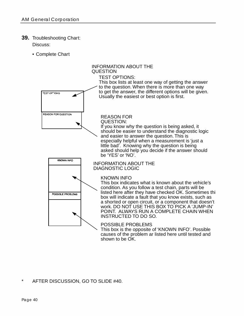
INFORMATION ABOUT THEQUESTION
TEST OPTIONS:This box lists at least one way of getting the answerto the question. When there is more than one wayto get the answer, the different options will be given. Usually the easiest or best option is first.
REASON FORQUESTION:If you know why the question is being asked, itshould be easier to understand the diagnostic logicand easier to answer the question. This is especially helpful when a measurement is ‘just alittle bad’. Knowing why the question is beingasked should help you decide if the answer shouldbe ‘YES’ or ‘NO’.
INFORMATION ABOUT THE DIAGNOSTIC LOGIC
KNOWN INFOThis box indicates what is known about the vehicle’scondition. As you follow a test chain, parts will be listed here after they have checked OK. Sometimes thisbox will indicate a fault that you know exists, such asa shorted or open circuit, or a component that doesn’twork. DO NOT USE THIS BOX TO PICK A ‘JUMP-IN’ POINT. ALWAYS RUN A COMPLETE CHAIN WHEN INSTRUCTED TO DO SO.
POSSIBLE PROBLEMSThis box is the opposite of ‘KNOWN INFO’. Possible causes of the problem ar listed here until tested and shown to be OK.

Page 41
40. Troubleshooting Chart:Discuss
• Complete Chart
* AFTER DISCUSSION GO TO SLIDE #41.

AM General Corporation
Page 42
41. Maintenance Task Initial Setup:Discuss:
• All Items
* AFTER DISCUSSION GO TO SIDE #42

Page 43
42. Maintenance Task Initial Setup:Discuss:
• All Items
* AFTER DISCUSSION GO TO SIDE #43

AM General Corporation
Page 44
43. Maintenance Allocation Chart:Discuss:
• Located in TM 9-2320-280-20-3, Appendix–B
* SLIDE DISCUSSION, GO TO SLIDE #44.

Page 45
44. Explanation of Columns in the MAC. Section II:
• Column #1-Group number: To identify the maintenance significant components, As-semblies, Subassemblies and modules with the next higher component.
• Column #2–Component/Assembly: Contains the names of components, assemblies, subassemblies and modules for which maintenance is authorized.
• Column #3–Maintenance Function: Functions to be performed on the item listed in col-umn #2.
• Column #4–Maintenance Level: This column lists the maintenance level authorized to perform the maintenance repair task and allowable maintenance time.Note: .1=6 minutes
C Operator or Crew
O Unit Maintenance
F Direct Support Maintenance
H General Support Maintenance
D Depot Maintenance
• Column #5–Tools and Equipment: This column specifies by code, those common tool sets and special tools, TMDE, required to perform the maintenance task.
• Column #6–Remarks: this column will contain a letter code which will be keyed to the remarks section.
* AFTER DISCUSSION GO TO SLIDE #45.

AM General Corporation
Page 46
45. Maintenance Allocation Chart:Discuss:
• All Columns
* AFTER DISCUSSION GO TO SLIDE #46

Page 47
46. Tools and test equipment requirements:Discuss
• All columns
* AFTER DISCUSSION, GO TO SLIDE #47.

AM General Corporation
Page 48
47. Tools and test equipment requirements:Discuss
• All columns
* AFTER DISCUSSION GO TO SLIDE #48.

Page 49
48. Remarks:Discuss:
• Codes
• Remarks
* AFTER DISCUSSION GO TO SLIDE #49.

AM General Corporation
Page 50
49. Parts Manual (TM 9-2320-280-24P-1)Discuss:
• Meaning of TM Numbers
• Meaning of-P/1, P/2 and P/3
• TM for vehicle Parts
* AFTER DISCUSSION, GO TO SLIDE #50.

Page 51
50. Parts Manual (TM 9-2815-237-34P)Discuss:
• Meaning of TM numbers
• Meaning of 34P
• TM for engine parts
* AFTER DISCUSSION GO TO SLIDE #51.

AM General Corporation
Page 52
51. Table of ContentsDiscuss:
• Use of Table
* AFTER DISCUSSION GO TO SLIDE #52.

Page 53
52. SMR Codes
• SMR codes are located in the front of the parts manual.
• The Source, Maintenance and Recoverability (SMR) code is a 5-position code con-taining supply/requisitioning information, maintenance category authorization criteria and disposition instructions, as shown in the following slide.
* AFTER DISCUSSION GO TO SLIDE #53.
SOURCE, MAINTENANCE, ANDRECOVERABILITY CODES
PAFZZ XAOZZ PAFHH PECOO PAOZZ PAHZZ PAOFF
SourceCode
MaintenanceCode
RecoverabilityCode
1st twopositions
3d postition 4th position Who determinesdispostionaction on anunservicable item
5th position
Who can docomplete repairon the item
Who can installreplace or usethe item
XX XX XX
How you get an item

AM General Corporation
Page 54
53. Source Code:Discuss: All items.
PA PBPC** PDPE PF PG
KD
KF
KB
MO Made at Org Level
MF Made at DS Level
MH Made at GS Level
ML Made at SRA/ Commercial
MD Made at Depot Level
AO Assembled by Org Level
AF Assembled by DS Level
AH Assembled by GS Level
AL Assembled by SRA/ Commercial
AD Assembled by Depot Level
XA
XB
XC
XD
Explanation
Stocked items; use the applicable NSN to request/req-uisition items with these source codes. They are autho-ized to the category indicated by the code entered in the 3rd position of the SMR code.**NOTE: Items coded PC are subject to deterioration.
Items with these codes are not to be requested/req-uisitioned individually. they are part of a kit which isauthorized to he maintenance category indicated inthe 3rd position of the SMR code. The complete kitmust be requisitioned and applied.
Items with these codes are not to be requested/req-uisitioned individually. They must be made from bulk material which is identified by the part number in the DESCRIPTION AND USABLE ON CODE (UCO) column and listed in the bulk material group of therepair parts list in the RPSTL. If the item is authorizedto you by the 3rd position code of the SMR code, butthe source code indicates it is made at a higher level, order the item from the higher level of maintenance.
Items with these codes are not to be requested/req-uisitioned individually. The parts that make up the assembled item must be requisitioned or fabricatedand assembled at the level of maintenance indicatedby the source code. If the 3rd position code of the SMR code authorized you to replace the item, but thesource code indicates the item is assembled at a higher level, order the item from the higher.
Do not requisition an “XA” coded item. Order its next higher assembly.
If an “XB” item is not available from salvage, order it using CAGEC and part number given
by manufacturer’s part number.
the CAGEC and part number given, if no NSN is available.
Installation drawing, diagram, instruction sheet, field service drawing, that is identified
Item is not stocked. Order and “XD” coded item through normal supply channels using

Page 55
54. Maintenance Codes:Discuss:
• Third position codes
• Fourth position codes
Third Position Codes
C Crew or operator maintenance done within organizational maintenance.
O Organizational level can remove, replace, and use the item.
F Direct support level can remove, replace, and use the item.
H General support level can remove, replace, and use the item.
L Specialized repair activity can remove, replace, and use the item.
D Depot level can remove, replace, and use the item.
Fourth Position Codes
O Organizational is the lowest level that can do complete repair of the item.
F Direct support is the lowest level that can do complete repair of the item.
H General Support s the lowest level that can do complete repair of the item
L Specialized repair activity (designate the specialized repair activity) is the lowestlevel that can do complete repair of the item
D Depot is the lowest level that can do complete repair of the item
Z Nonreparable. No repair is authorized.
B No repair is authorized. (No parts or special tools are authorized for the mainte-nance of a “B” coded item.) However, the item may be reconditioned by adjusting,lubricating, etc. at the user level.
* AFTER DISCUSSION, GO TO SLIDE #55.

AM General Corporation
Page 56
55. Recoverability Codes:Discuss:
• All Codes
Z Nonreparable item. When unserviceable, condemn and dispose of the item at thelevel of maintenance shown in 3d position of SMR code.
O Reparable item. When uneconomically reparable, condemn and dispose of the item at organizational level.
F Reparable item. When uneconomically reparable, condemn and dispose of the item at the direct support level.
H Reparable item. When uneconomically reparable, condemn and dispose of the item at the general support level.
D Reparable item. When beyond lower level repair capability, return to depot. Con-demnation and disposal of item not authorized below depot level.
L Reparable item. Condemnation and disposal not authorized below specialized repair activity (SRA).
A Item requires special handling or condemnation procedures because of specificreasons (e.g.; precious metal content, high dollar value, critical material, or haz-ardous material). refer to appropriate manuals/directives for specific instructions.
* AFTER DISCUSSION, GO TO SLIDE #56.

Page 57
56. Parts Identification:Discuss:
1. Item Column: The item number identifies a part or tool in the associated figure.
2. SMR Code: Source, Maintenance, Recoverability codes.
3. CAGEC Column: A 5-digit numeric code which is used to identify the manufactureror government agency that supplies the item.
4. Part Number: Indicates the primary number used by the manufacturer, corporation,or government activity that supplies the item.
5. Description and Usable-on Code (UOC): This column identifies the vehicle that thepart is used on.
6. Qty. Column: Indicates the quanitity of the item used on the component or vehicle.
* AFTER DISCUSSION GO TO SLIDE #57.

AM General Corporation
Page 58
57. Usable on Code (UOC)
• The UOC is found in the front of the manual.
• The usable on code appears on the lower left-hand corner of the description column heading. Uncoded items are applicable to all models.
* AFTER DISCUSSION GO TO SLIDE #58.

Page 59
58. Special Tools:Discuss:
• Show tool slide
• All columns
END OF PROGRAM.


