HP 5820X & 5800 Switch Series Fundamentals Configuration Guide Abstract This document describes the software features for the HP 5820X & 5800 Series products and guides you through the software configuration procedures. These configuration guides also provide configuration examples to help you apply software features to different network scenarios. This documentation is intended for network planners, field technical support and servicing engineers, and network administrators working with the HP 5820X & 5800 Series products. Part number: 5998-1620 Software version: Release 1211 Document version: 6W102-20130520
Transcript
HP 5820X & 5800 Switch Series Fundamentals
Configuration Guide
Abstract
This document describes the software features for the HP 5820X & 5800 Series products and guides you through the software configuration procedures. These configuration guides also provide configuration examples to help you apply software features to different network scenarios.
This documentation is intended for network planners, field technical support and servicing engineers, and network administrators working with the HP 5820X & 5800 Series products.
Part number: 5998-1620 Software version: Release 1211 Document version: 6W102-20130520
No part of this documentation may be reproduced or transmitted in any form or by any means without prior written consent of Hewlett-Packard Development Company, L.P.
The information contained herein is subject to change without notice.
HEWLETT-PACKARD COMPANY MAKES NO WARRANTY OF ANY KIND WITH REGARD TO THIS MATERIAL, INCLUDING, BUT NOT LIMITED TO, THE IMPLIED WARRANTIES OF MERCHANTABILITY AND FITNESS FOR A PARTICULAR PURPOSE. Hewlett-Packard shall not be liable for errors contained herein or for incidental or consequential damages in connection with the furnishing, performance, or use of this material.
The only warranties for HP products and services are set forth in the express warranty statements accompanying such products and services. Nothing herein should be construed as constituting an additional warranty. HP shall not be liable for technical or editorial errors or omissions contained herein.
iii
Contents
Configuring the CLI ······················································································································································ 1 Entering the CLI ································································································································································· 1 Command conventions ····················································································································································· 2 Undo form of a command ················································································································································ 3 CLI view description ·························································································································································· 3
Entering system view ················································································································································ 4 Exiting the current view ··········································································································································· 4 Returning to user view ·············································································································································· 4
Using online help ······························································································································································ 5 Entering commands ·························································································································································· 6
Checking command line errors ······································································································································· 9 Using command history ···················································································································································· 9
Accessing history commands ·································································································································· 9 Configuring the history buffer size ······················································································································ 10
Controlling the CLI display ············································································································································ 10 Multi-screen display ·············································································································································· 10 Filtering output information ·································································································································· 11
Configuring user privilege and command levels ········································································································ 14 Configuring a user privilege level ······················································································································· 15 Switching user privilege level ······························································································································· 18 Modifying the level of a command ····················································································································· 20
Saving the current configuration ·································································································································· 21 Displaying and maintaining CLI ··································································································································· 21
Login methods ···························································································································································· 22 Users and user interfaces ·············································································································································· 23
Numbering user interfaces ··································································································································· 24
CLI login ······································································································································································ 25 Logging in through the console port ···························································································································· 25
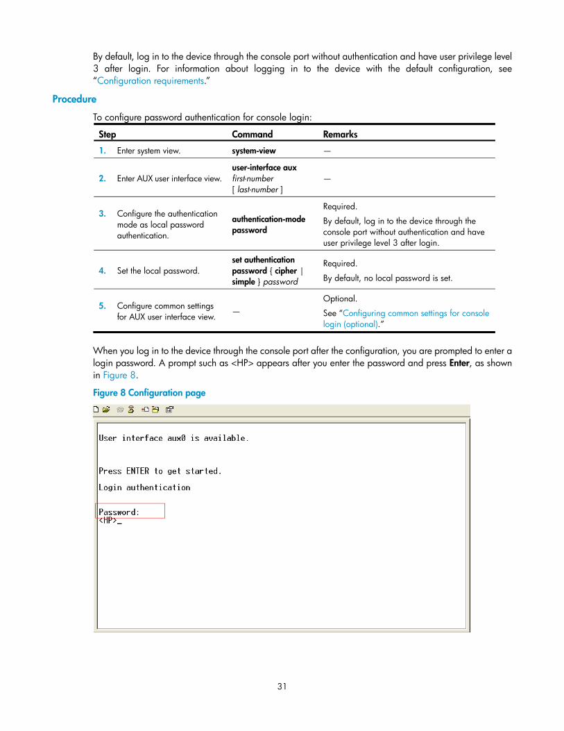
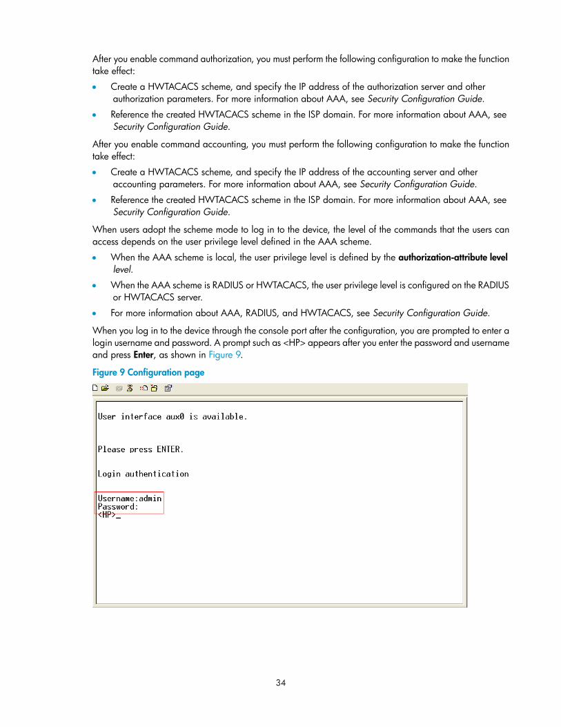
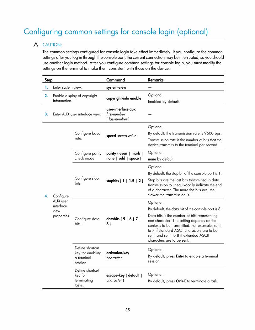
Configuration requirements ·································································································································· 25 Login procedure ····················································································································································· 26 Console login authentication modes ··················································································································· 28 Configuring none authentication for console login ··························································································· 29 Configuring password authentication for console login ··················································································· 30 Configuring scheme authentication for console login ······················································································· 32 Configuring common settings for console login (optional) ··············································································· 35
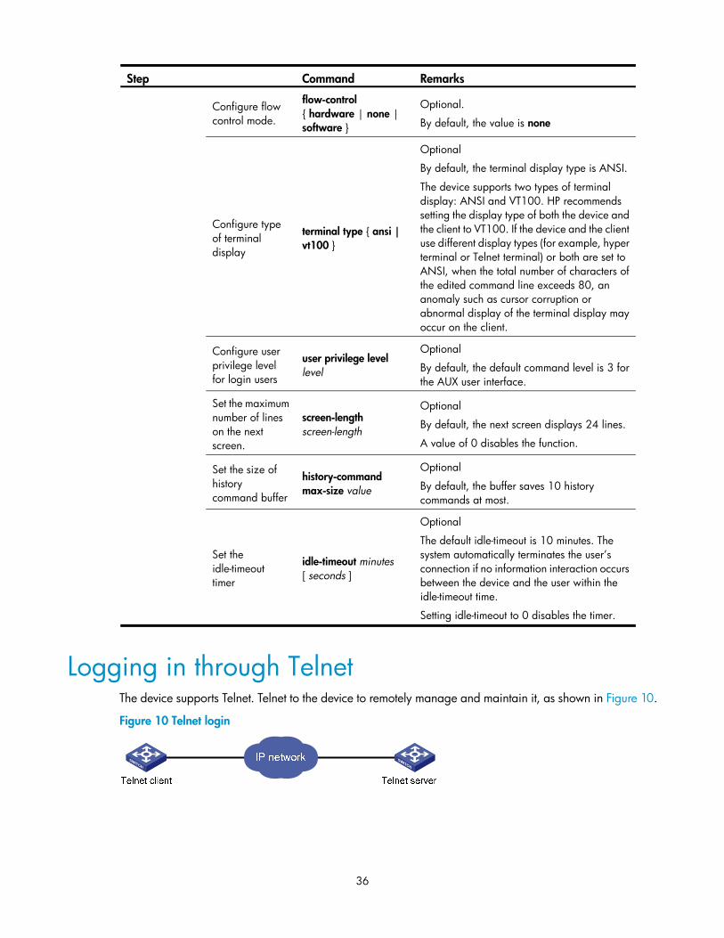
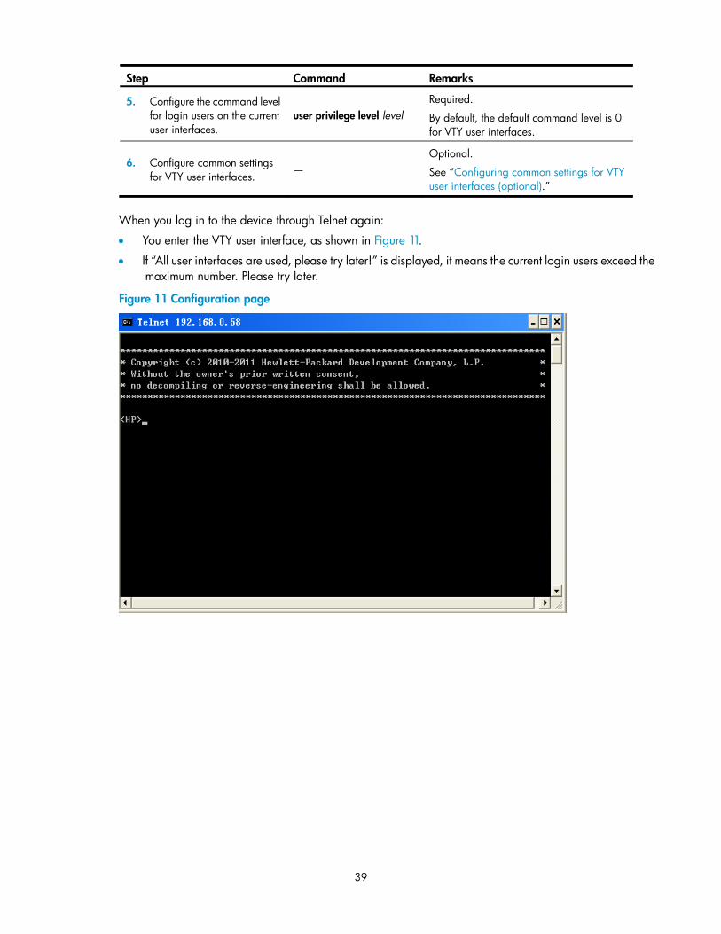
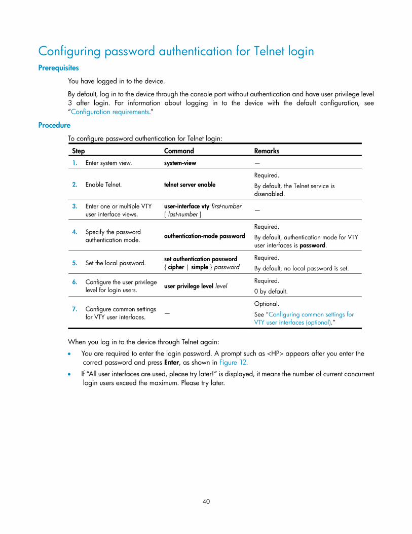
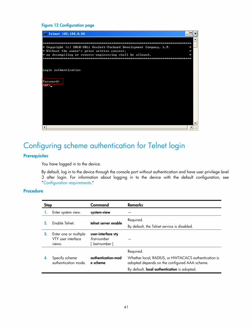
Logging in through Telnet ·············································································································································· 36 Telnet login authentication modes ······················································································································· 37 Configuring none authentication for Telnet login ······························································································ 38 Configuring password authentication for Telnet login ······················································································ 40 Configuring scheme authentication for Telnet login ·························································································· 41 Configuring common settings for VTY user interfaces (optional)······································································ 44 Configuring the device to log in to a Telnet server as a Telnet client ······························································ 46
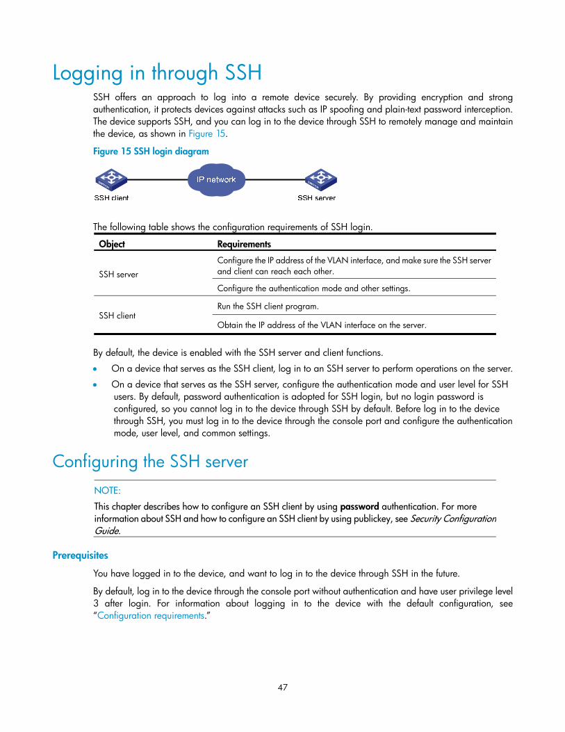
Logging in through SSH ················································································································································ 47
iv
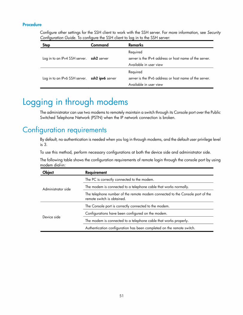
Configuring the SSH server ·································································································································· 47 Configuring the SSH client to log in to the SSH server ····················································································· 50
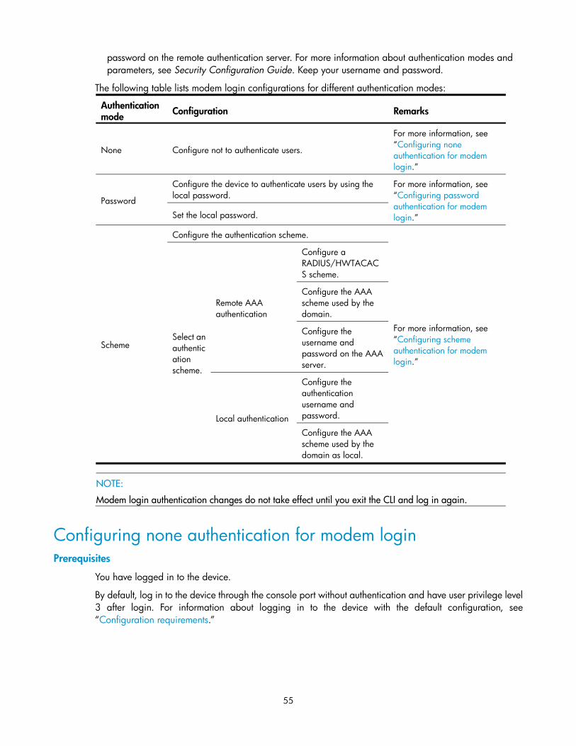
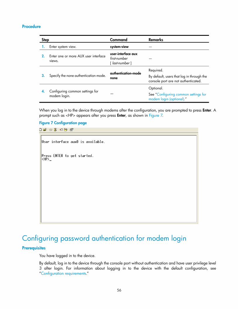
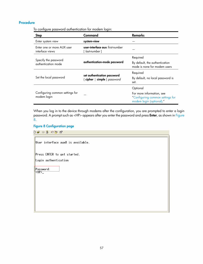
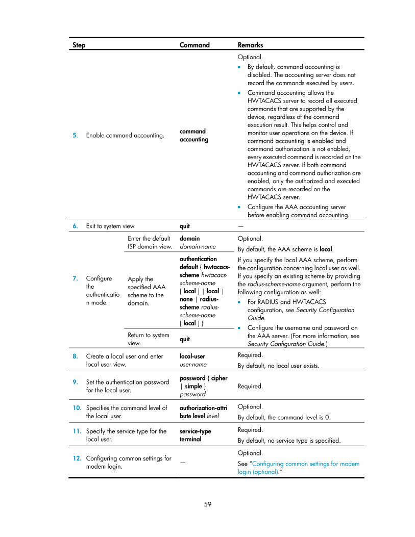
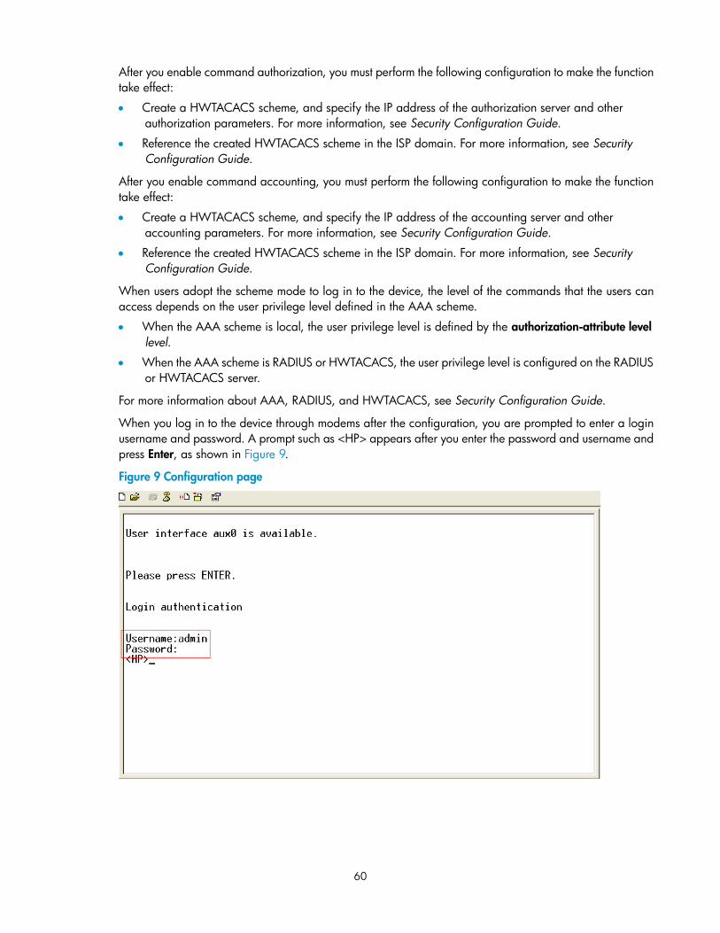
Logging in through modems ········································································································································· 51 Configuration requirements ·································································································································· 51 Login procedure ····················································································································································· 52 Modem login authentication modes ···················································································································· 54 Configuring none authentication for modem login ···························································································· 55 Configuring password authentication for modem login ···················································································· 56 Configuring scheme authentication for modem login ······················································································· 58 Configuring common settings for modem login (optional) ················································································ 61
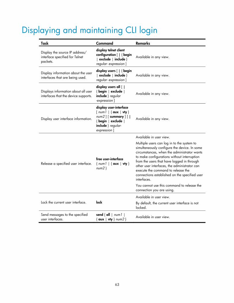
Displaying and maintaining CLI login ························································································································· 63
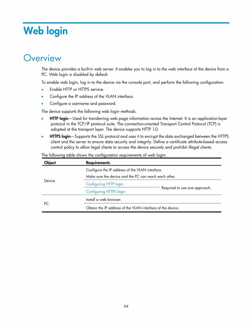
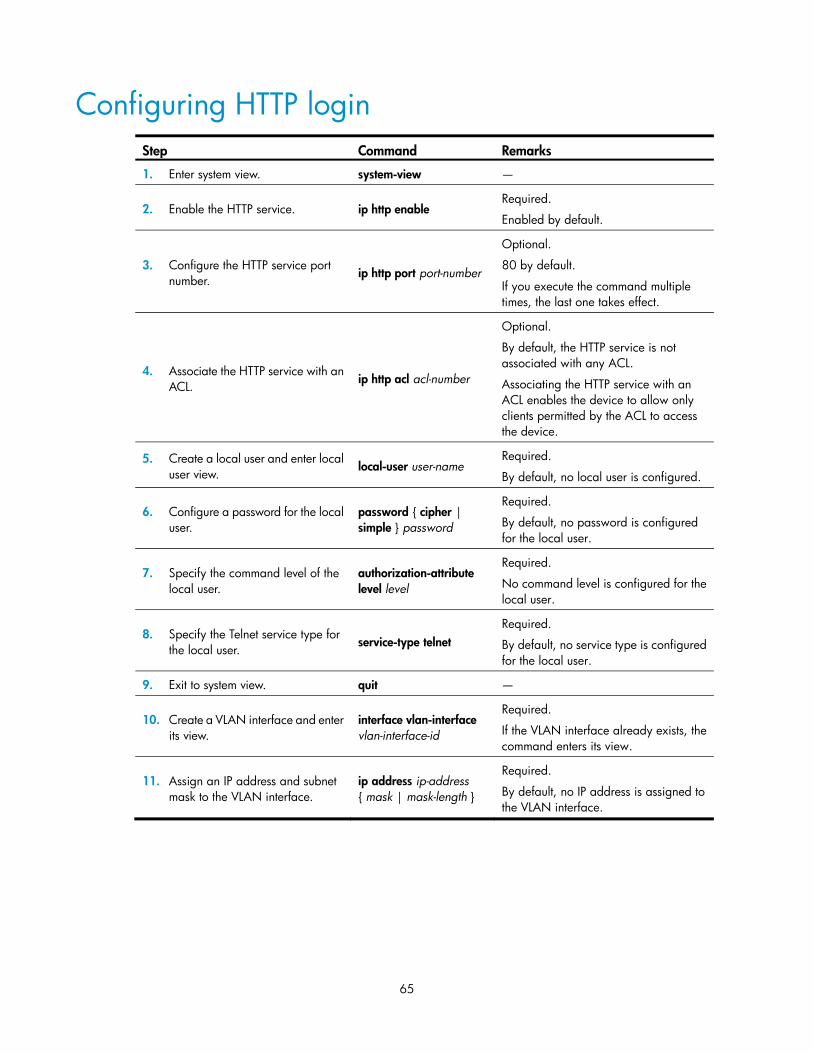
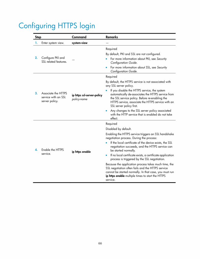
Web login ·································································································································································· 64 Overview········································································································································································· 64 Configuring HTTP login ················································································································································· 65 Configuring HTTPS login ··············································································································································· 66 Displaying and maintaining web login ······················································································································· 68 Web login example ······················································································································································· 68
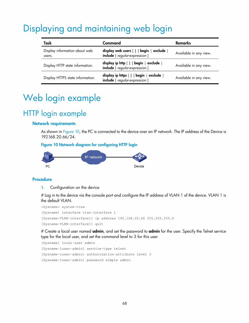
HTTP login example ·············································································································································· 68 HTTPS login example ············································································································································ 69
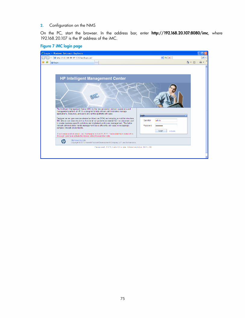
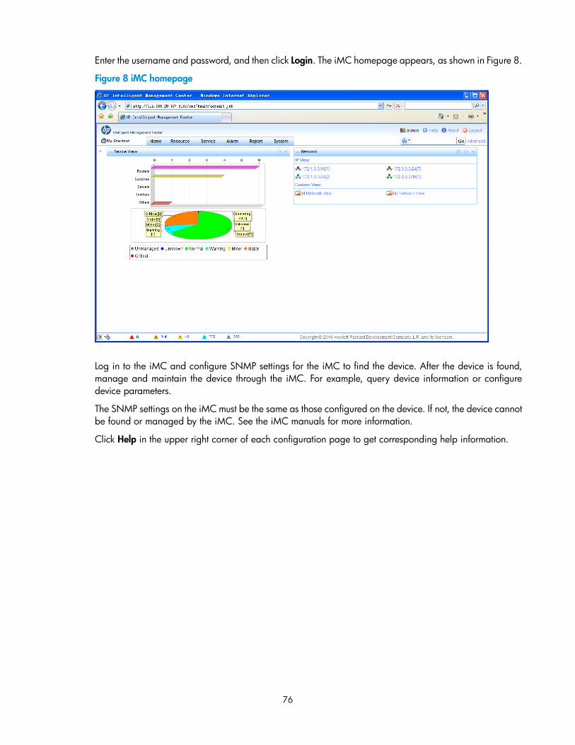
NMS login example ······················································································································································ 74
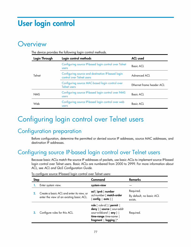
User login control ······················································································································································· 77 Overview········································································································································································· 77 Configuring login control over Telnet users ················································································································· 77
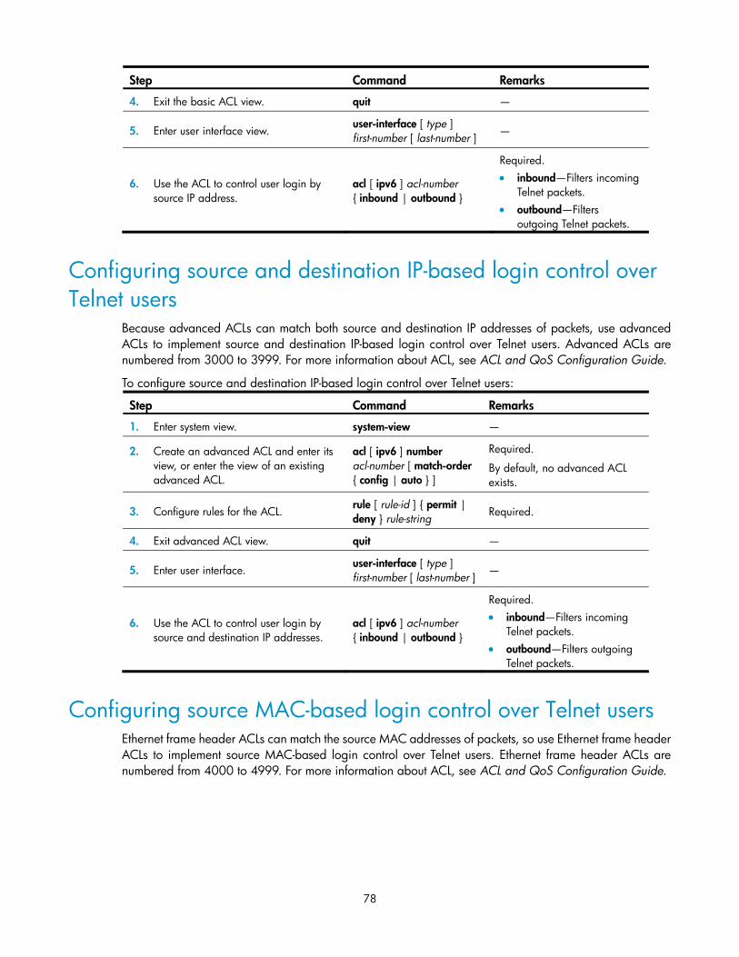
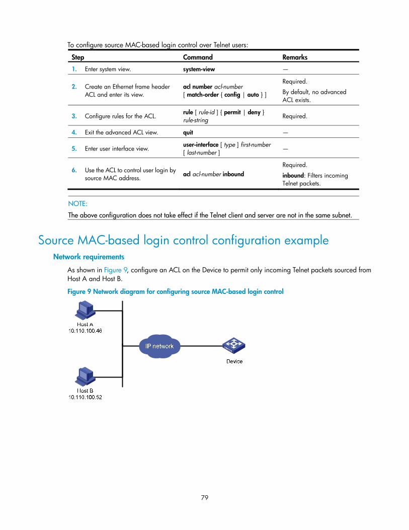
Configuration preparation ··································································································································· 77 Configuring source IP-based login control over Telnet users ············································································ 77 Configuring source and destination IP-based login control over Telnet users ················································ 78 Configuring source MAC-based login control over Telnet users ······································································ 78 Source MAC-based login control configuration example ················································································· 79
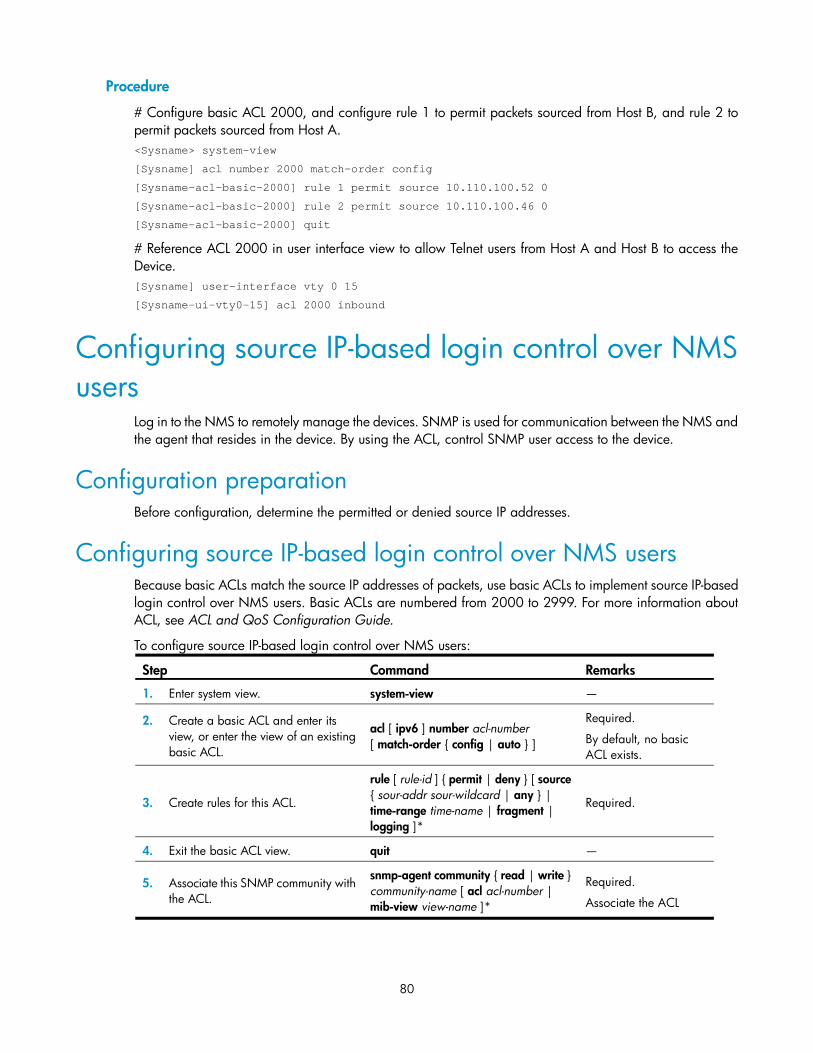
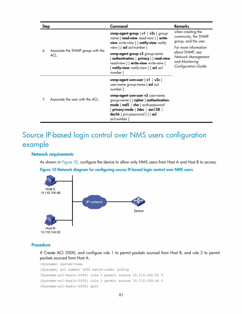
Configuring source IP-based login control over NMS users ······················································································ 80 Configuration preparation ··································································································································· 80 Configuring source IP-based login control over NMS users ············································································· 80 Source IP-based login control over NMS users configuration example ·························································· 81
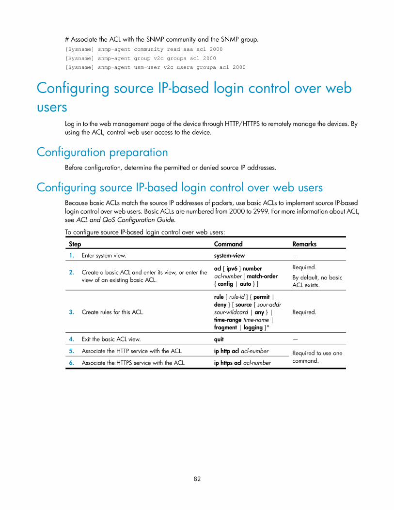
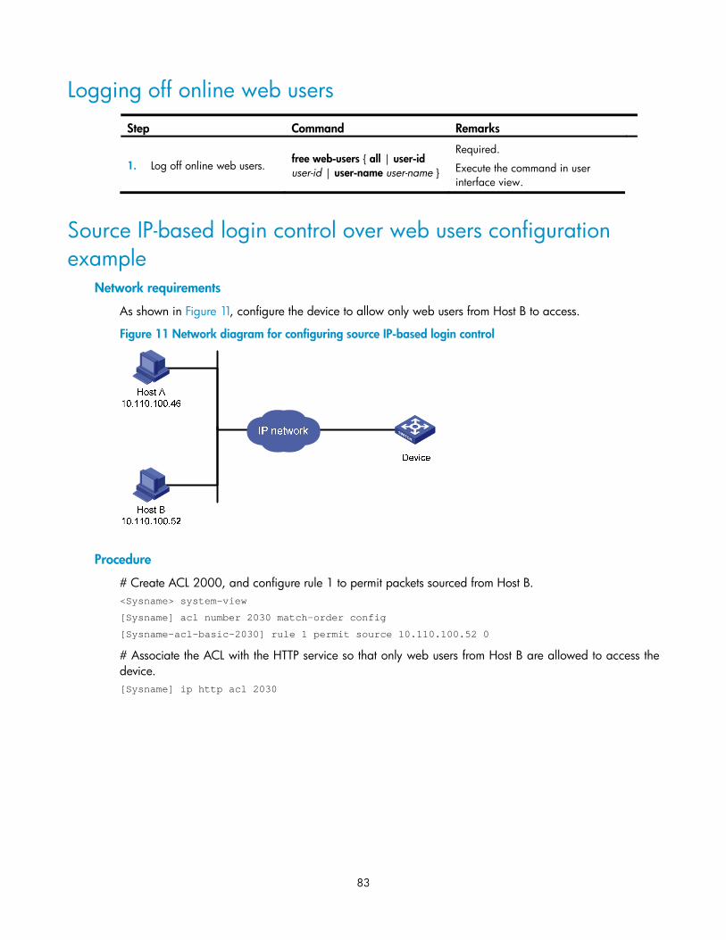
Configuring source IP-based login control over web users ······················································································· 82 Configuration preparation ··································································································································· 82 Configuring source IP-based login control over web users ··············································································· 82 Logging off online web users ······························································································································· 83 Source IP-based login control over web users configuration example ···························································· 83
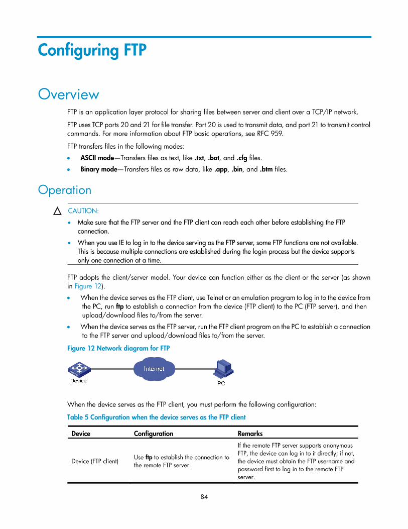
Operation ······························································································································································· 84 Configuring the FTP client ············································································································································· 85
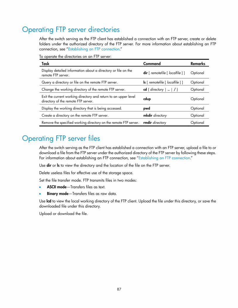
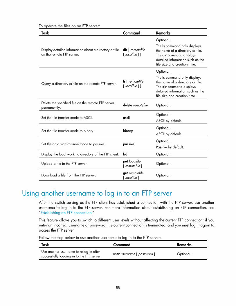
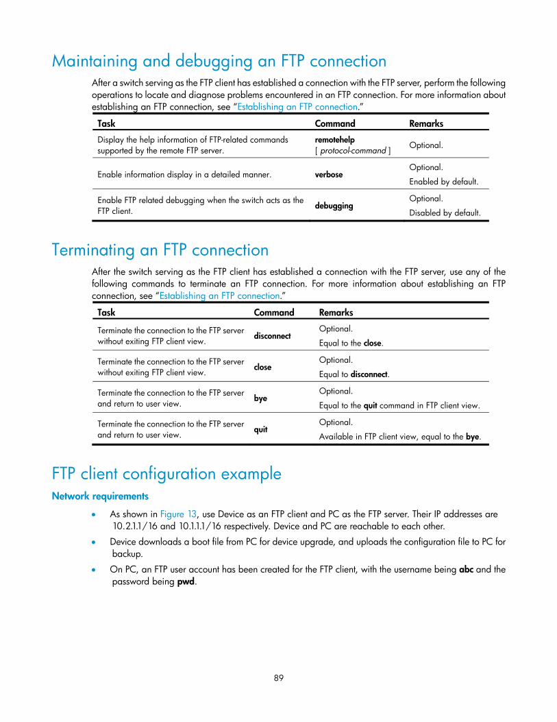
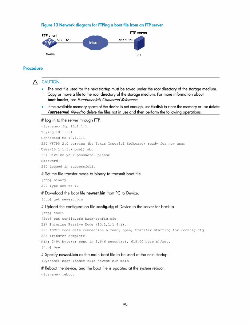
Establishing an FTP connection ···························································································································· 85 Operating FTP server directories ························································································································· 87 Operating FTP server files ···································································································································· 87 Using another username to log in to an FTP server ··························································································· 88 Maintaining and debugging an FTP connection ································································································ 89 Terminating an FTP connection ···························································································································· 89 FTP client configuration example ························································································································· 89
v
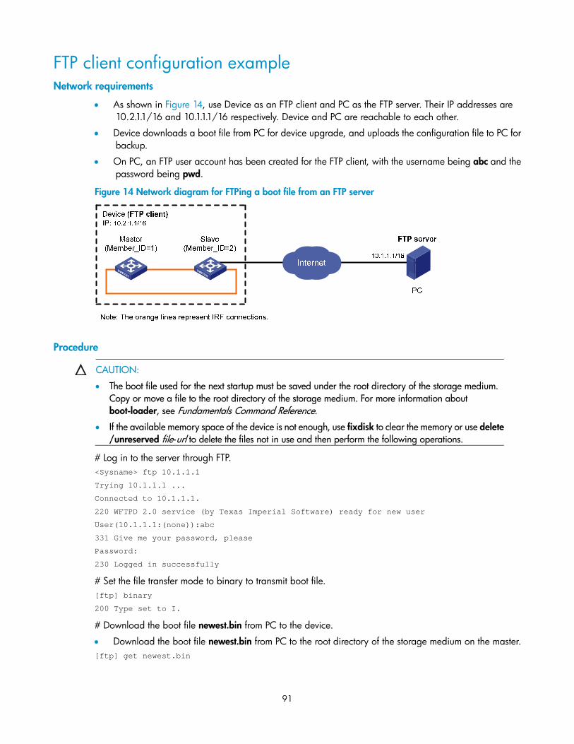
FTP client configuration example ························································································································· 91 Configuring the FTP server ············································································································································ 92
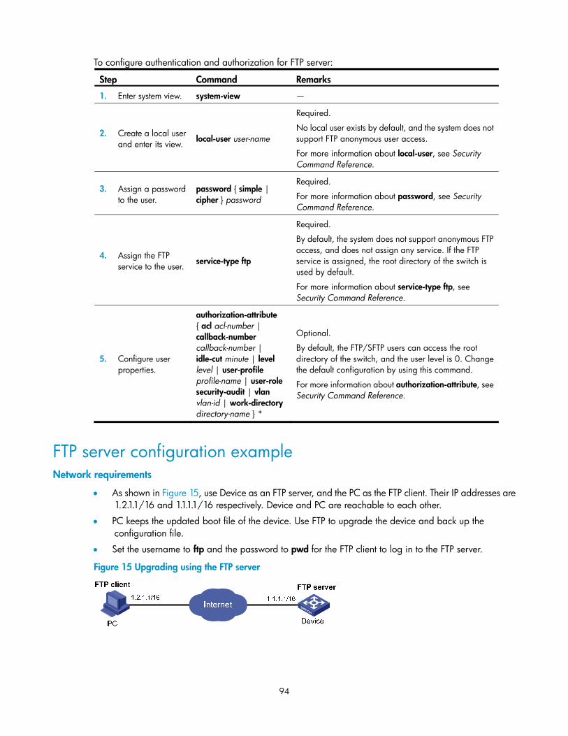
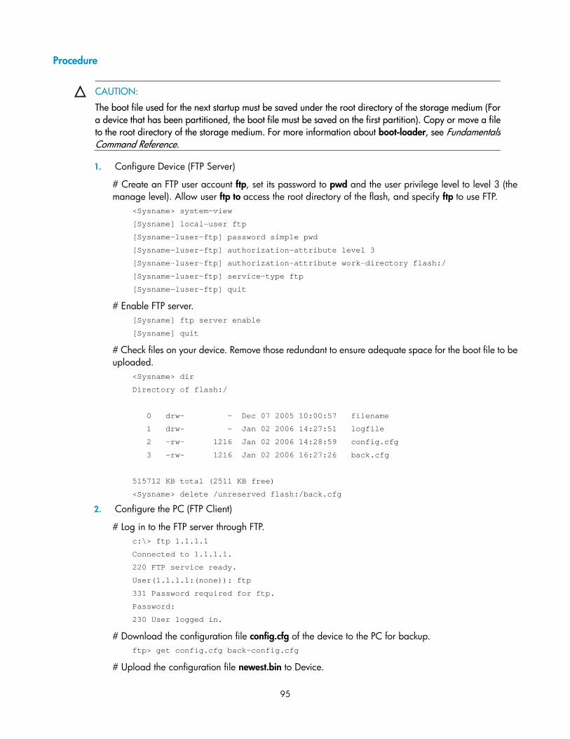
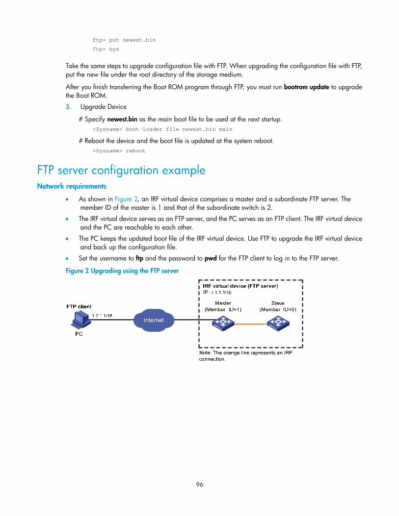
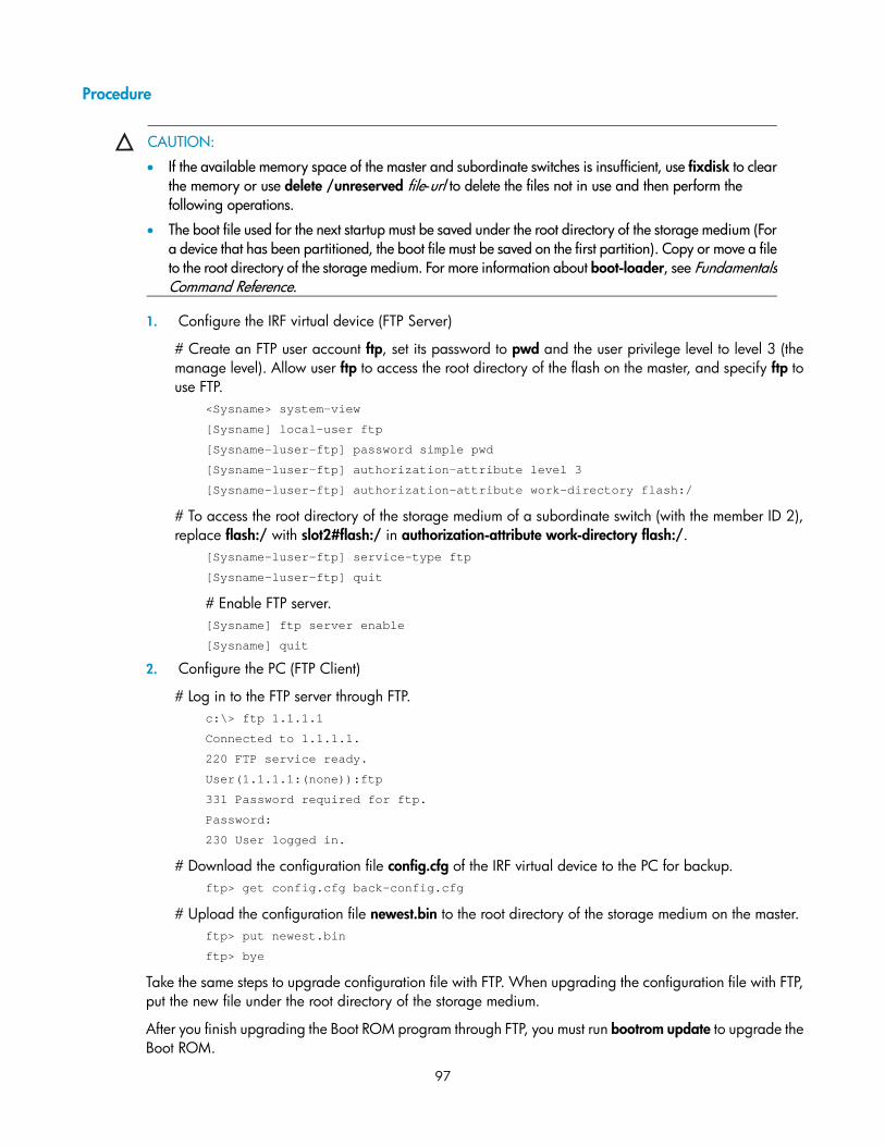
Configuring FTP server operating parameters ··································································································· 92 Configuring authentication and authorization on the FTP server ····································································· 93 FTP server configuration example ························································································································ 94 FTP server configuration example ························································································································ 96
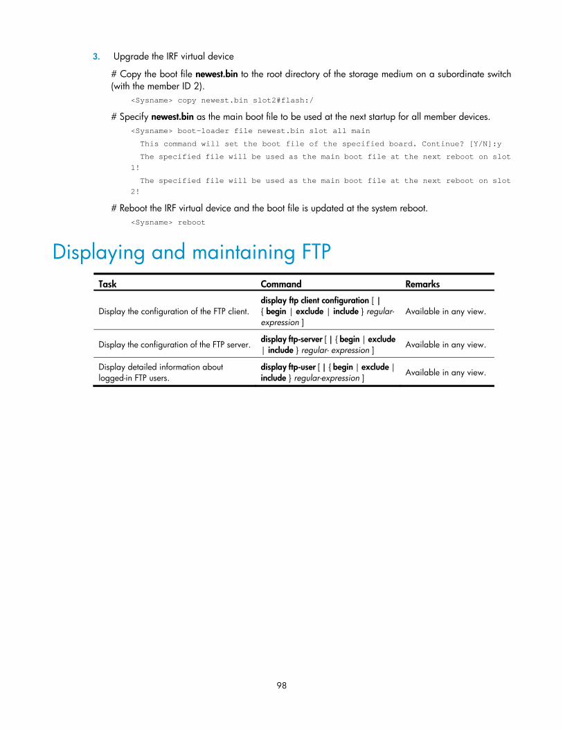
Displaying and maintaining FTP ··································································································································· 98
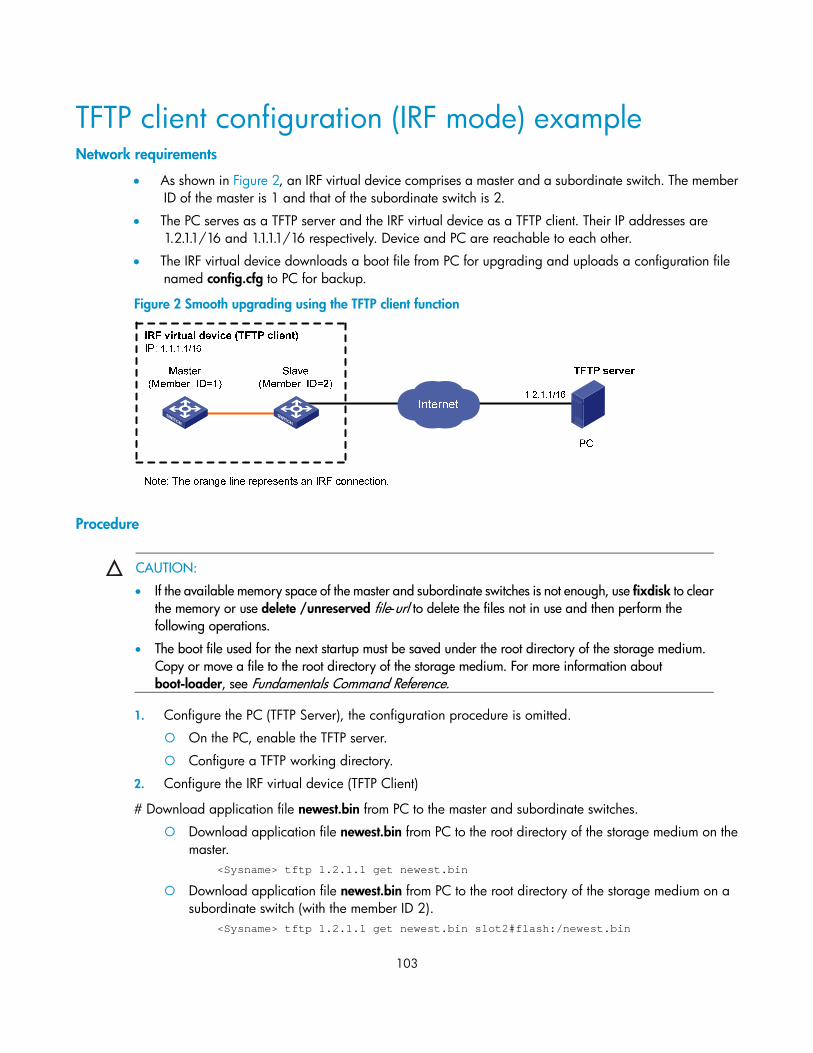
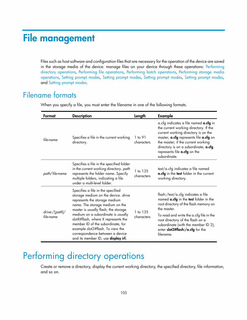
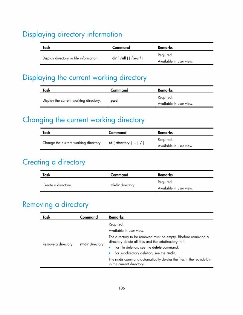
Performing directory operations ································································································································· 105 Displaying directory information ······················································································································· 106 Displaying the current working directory ·········································································································· 106 Changing the current working directory ··········································································································· 106 Creating a directory ············································································································································ 106 Removing a directory ·········································································································································· 106
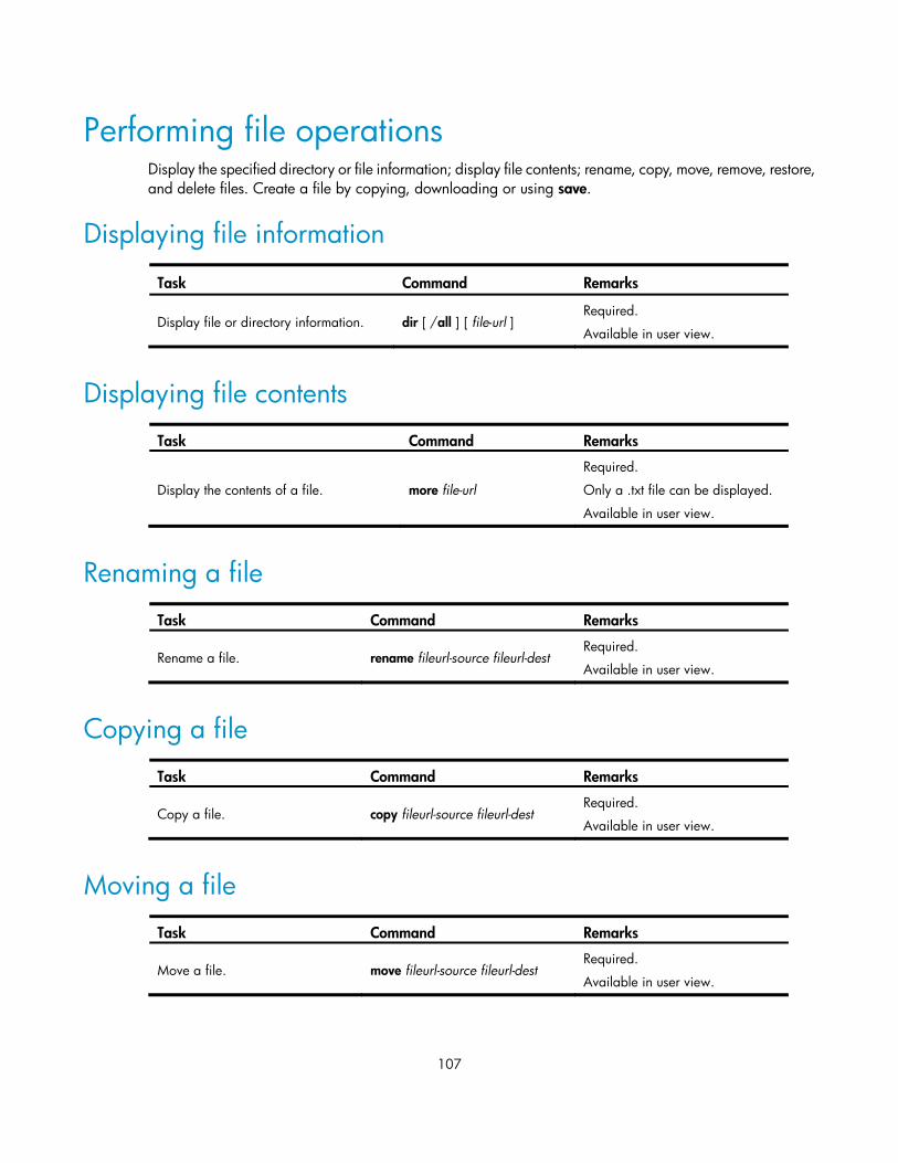
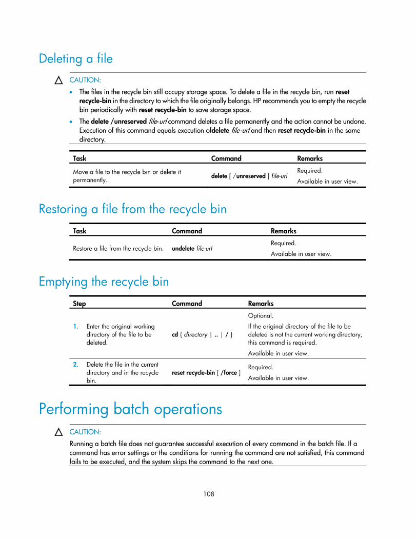
Performing file operations ··········································································································································· 107 Displaying file information ································································································································· 107 Displaying file contents ······································································································································· 107 Renaming a file···················································································································································· 107 Copying a file ······················································································································································ 107 Moving a file························································································································································ 107 Deleting a file ······················································································································································ 108 Restoring a file from the recycle bin ·················································································································· 108 Emptying the recycle bin ···································································································································· 108
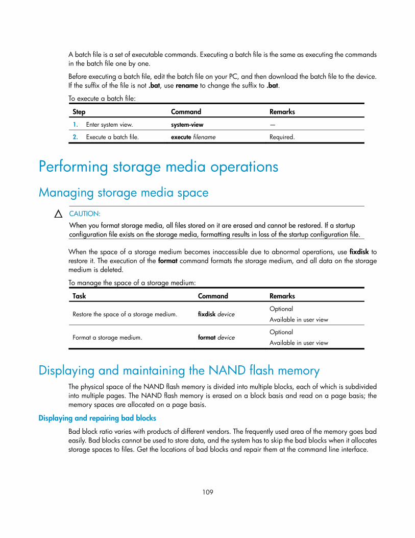
Managing storage media space ······················································································································· 109 Displaying and maintaining the NAND flash memory ··················································································· 109
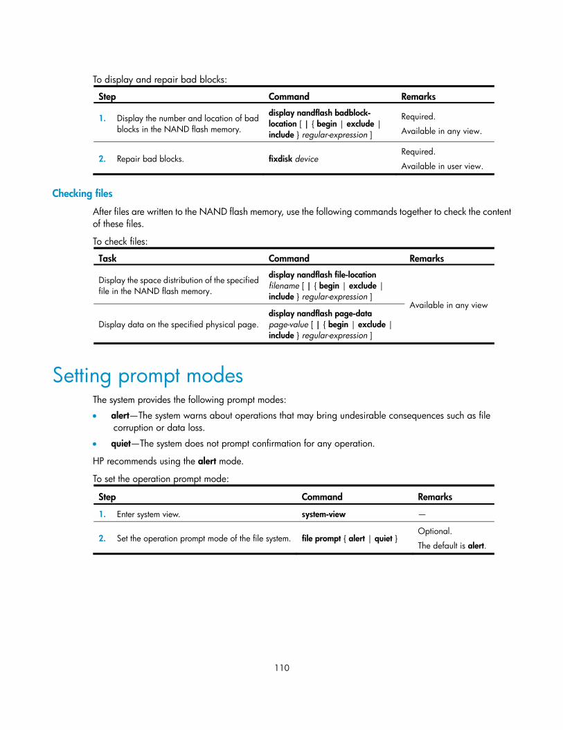
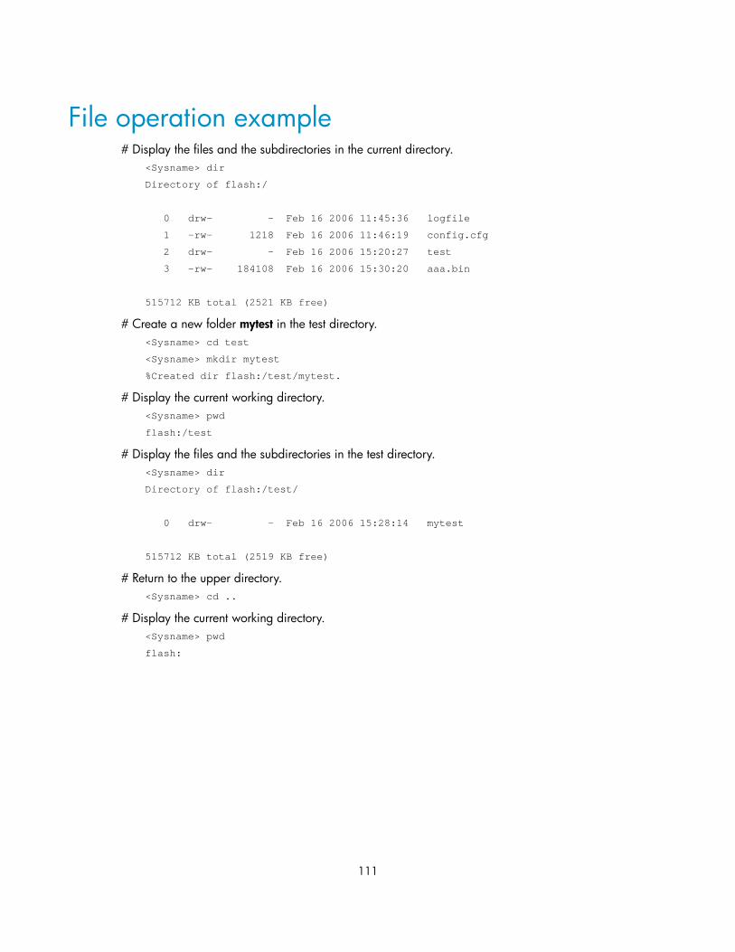
Setting prompt modes ·················································································································································· 110 File operation example ················································································································································ 111
Types of configuration ········································································································································ 112 Configuration file format and content ··············································································································· 113 Coexistence of multiple configuration files ······································································································· 113 Startup with the configuration file ······················································································································ 114
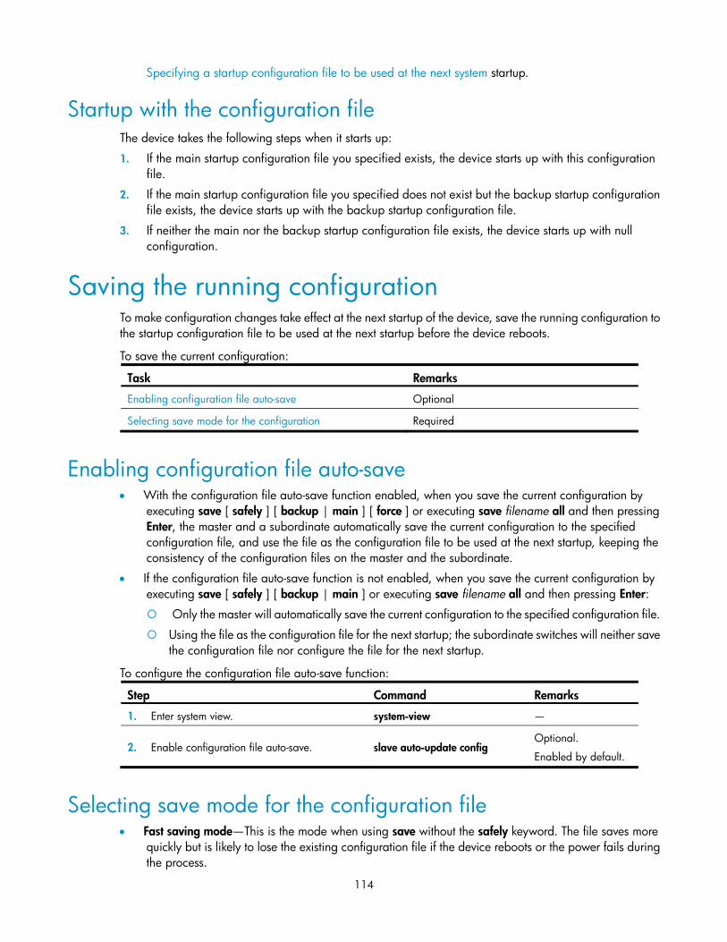
Saving the running configuration ······························································································································· 114 Enabling configuration file auto-save ················································································································ 114 Selecting save mode for the configuration file ································································································· 114
Setting configuration rollback ····································································································································· 117 Configuration task list ········································································································································· 117 Configuring parameters for saving the running configuration ······································································· 118 Enabling automatic saving of the running configuration ················································································ 119 Manually saving the running configuration ······································································································ 120 Setting configuration rollback ···························································································································· 120
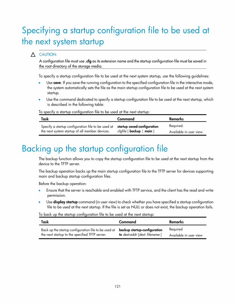
Specifying a startup configuration file to be used at the next system startup ························································ 121
vi
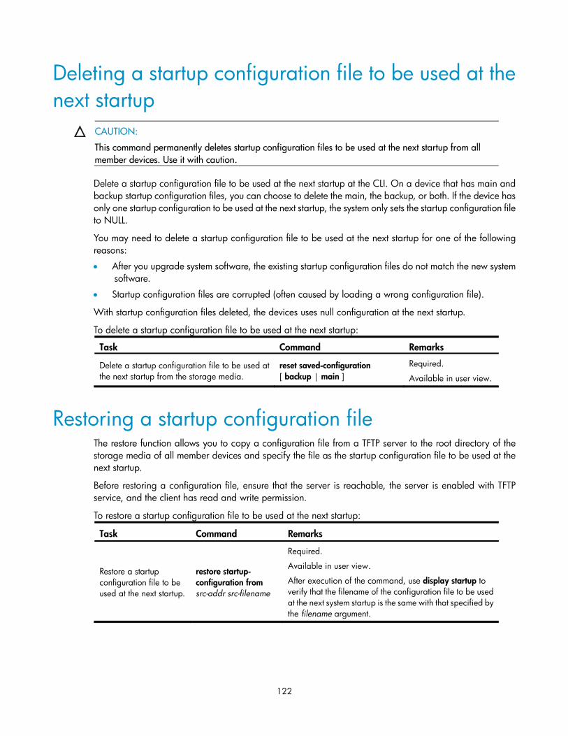
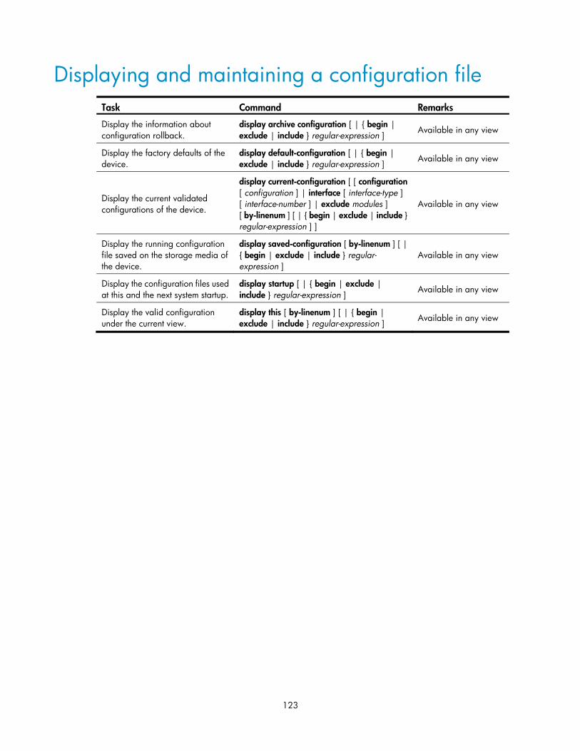
Backing up the startup configuration file ··················································································································· 121 Deleting a startup configuration file to be used at the next startup ········································································ 122 Restoring a startup configuration file ························································································································· 122 Displaying and maintaining a configuration file ······································································································ 123
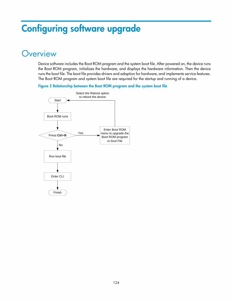
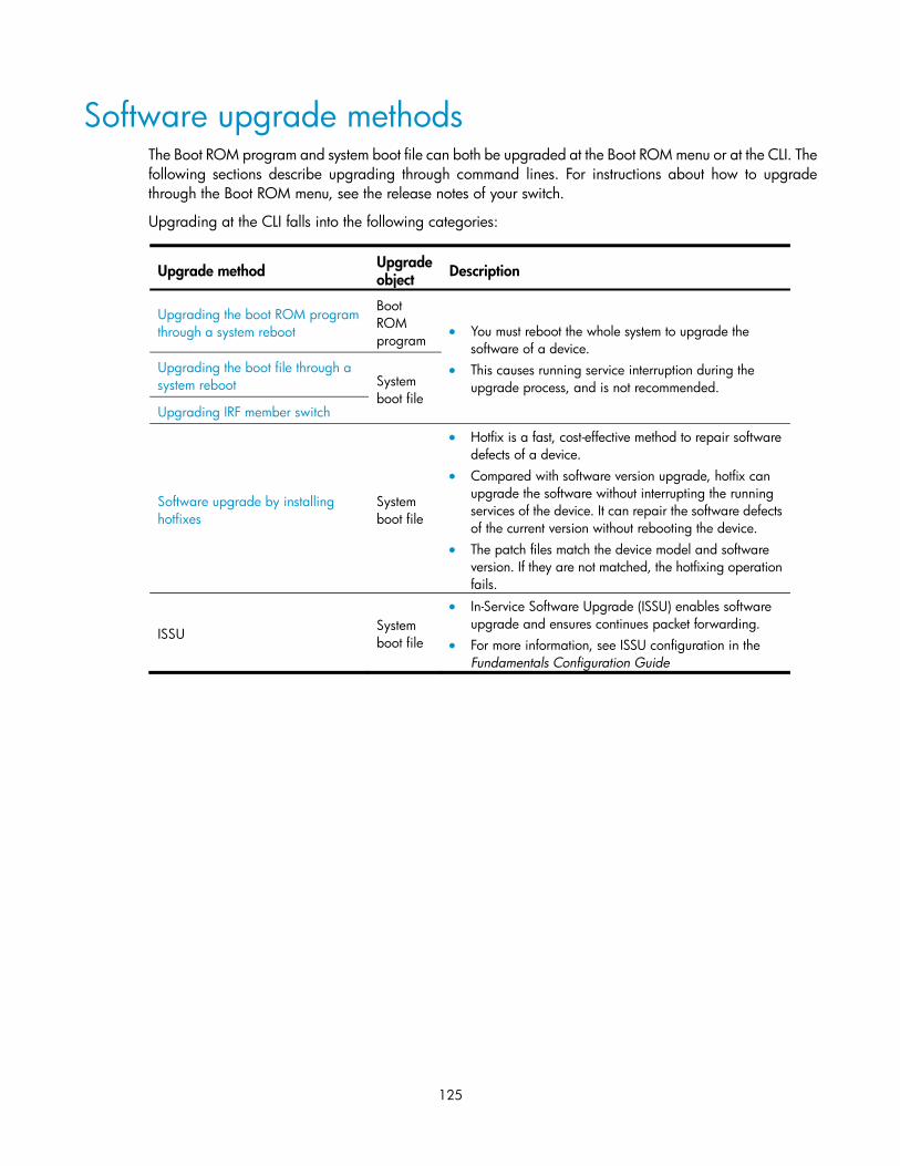
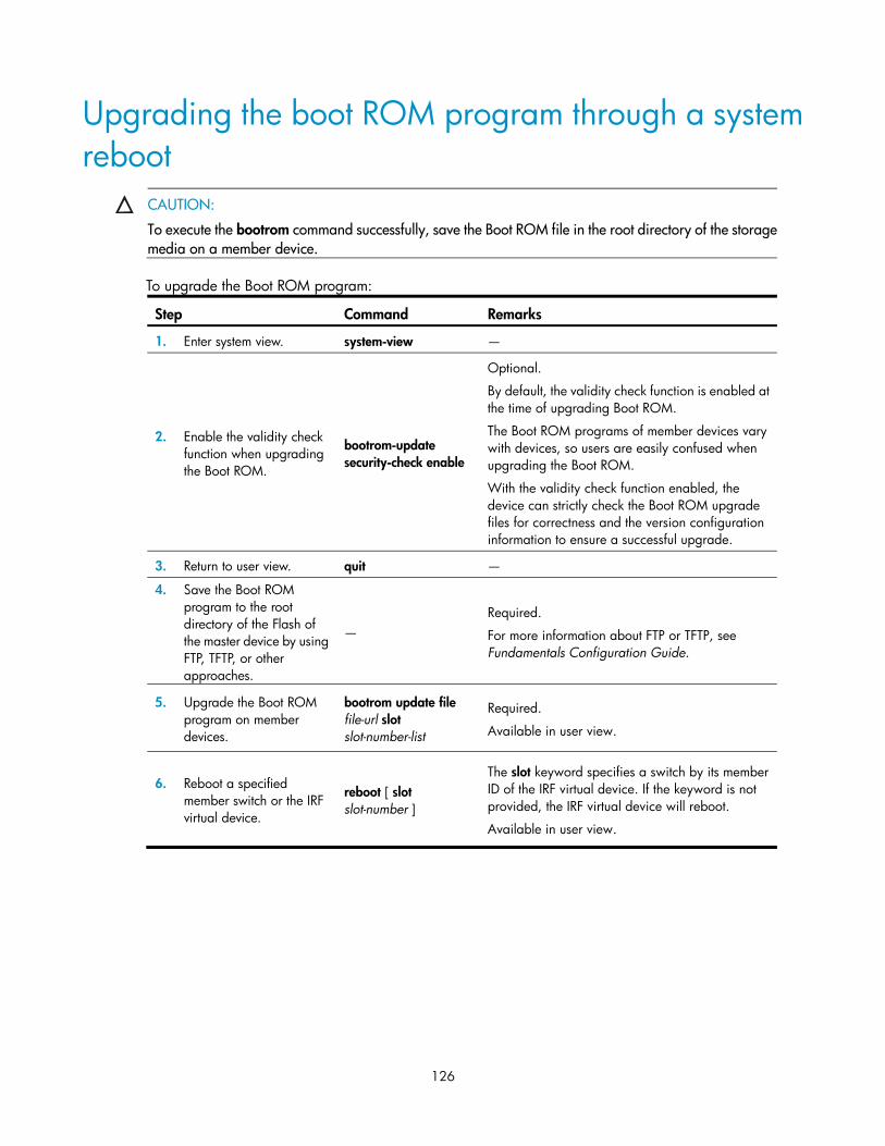
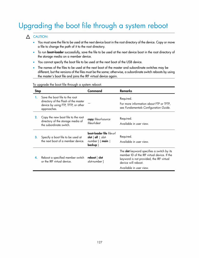
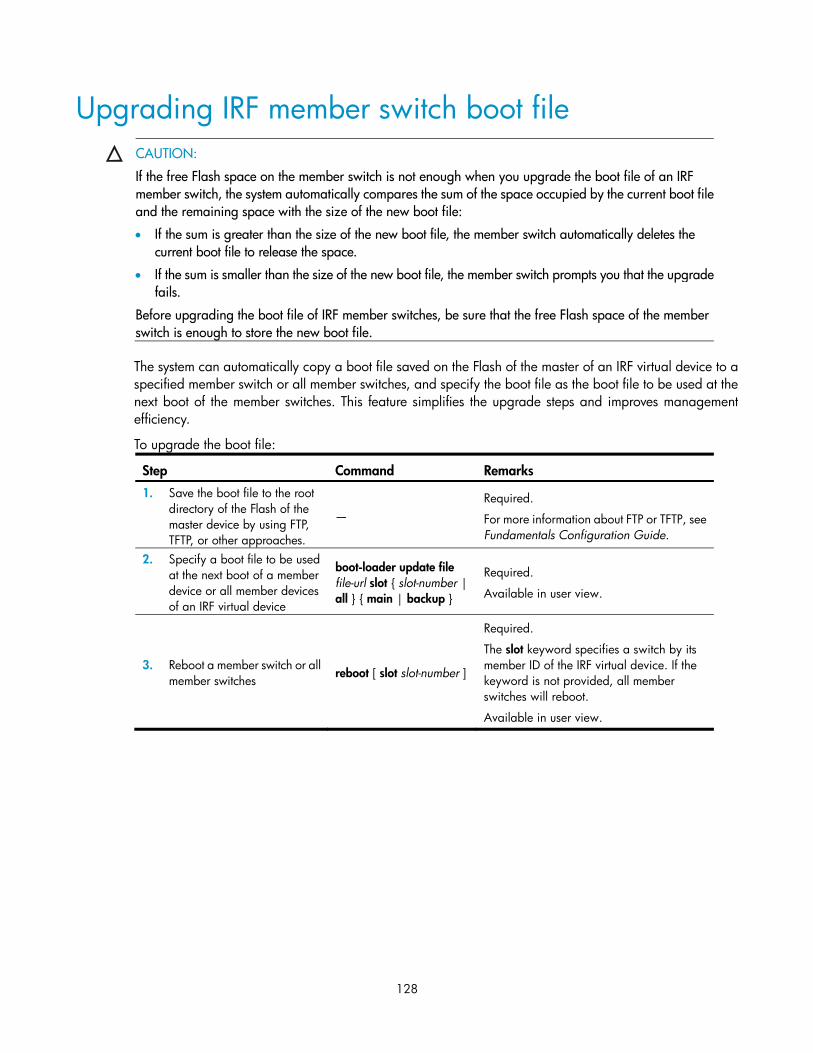
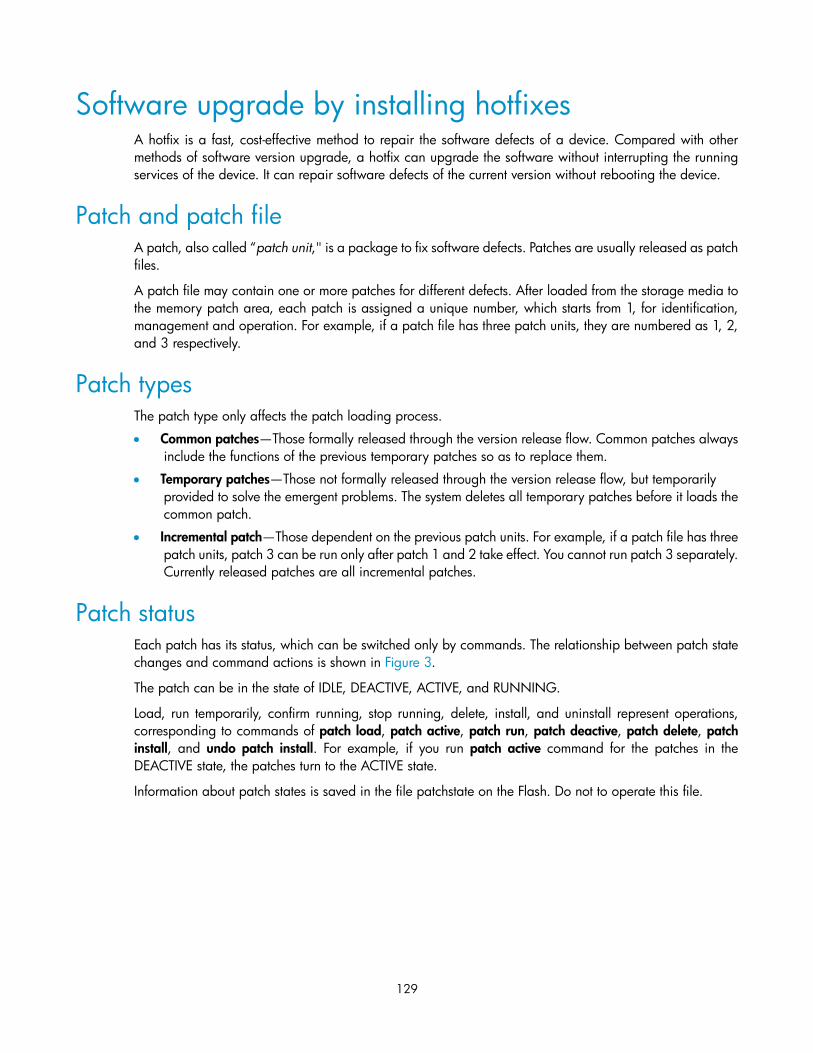
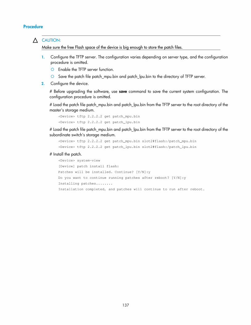
Configuring software upgrade ······························································································································· 124 Overview······································································································································································· 124 Software upgrade methods ········································································································································· 125 Upgrading the boot ROM program through a system reboot················································································· 126 Upgrading the boot file through a system reboot ····································································································· 127 Upgrading IRF member switch boot file ···················································································································· 128 Software upgrade by installing hotfixes ···················································································································· 129
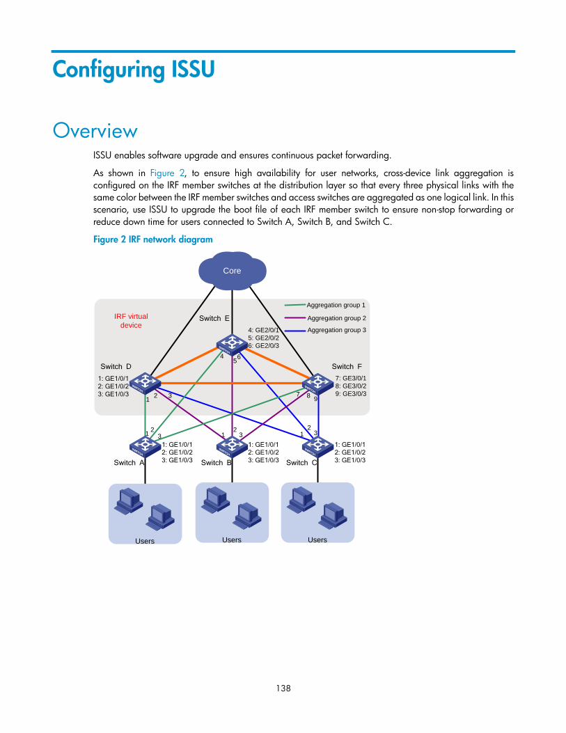
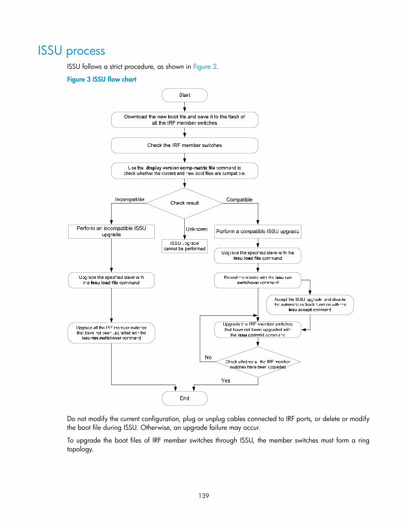
ISSU process ························································································································································ 139 Boot file version rollback ···································································································································· 140
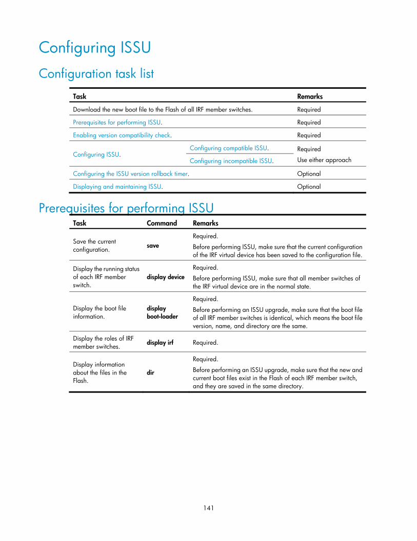
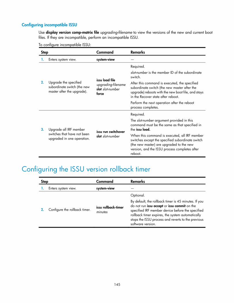
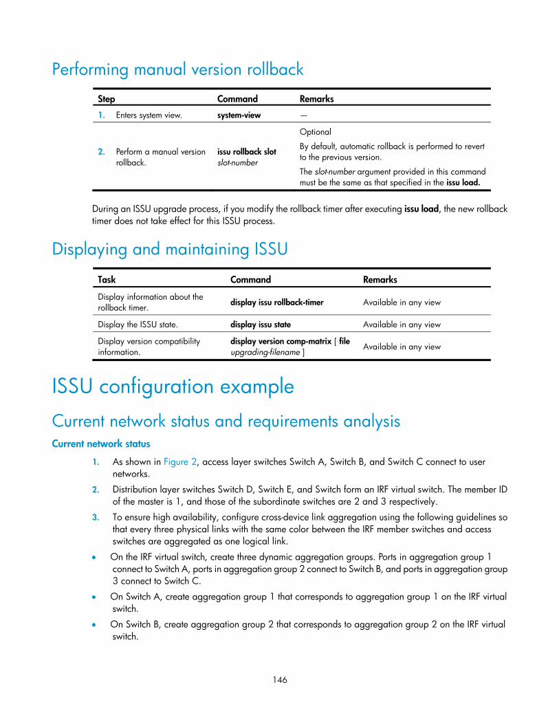
Configuring ISSU ························································································································································· 141 Configuration task list ········································································································································· 141 Prerequisites for performing ISSU ······················································································································ 141 Enabling version compatibility check ················································································································ 142 Configuring ISSU ················································································································································· 143 Configuring the ISSU version rollback timer····································································································· 145 Performing manual version rollback ·················································································································· 146 Displaying and maintaining ISSU ······················································································································ 146
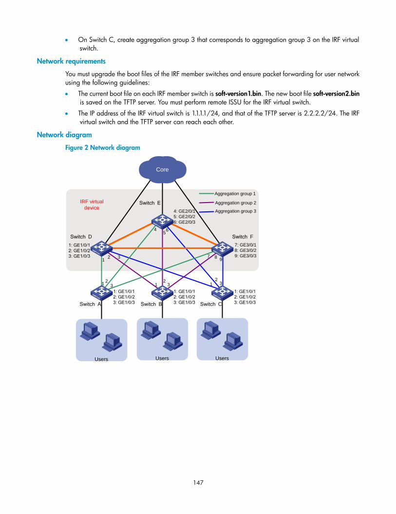
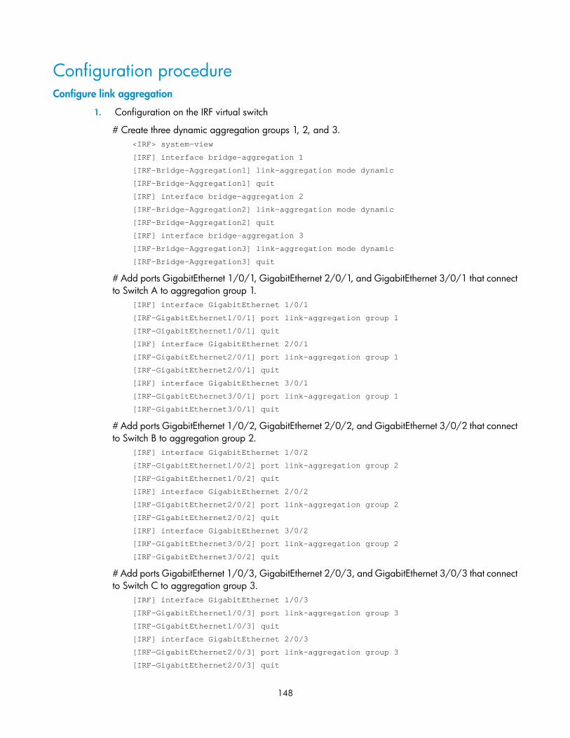
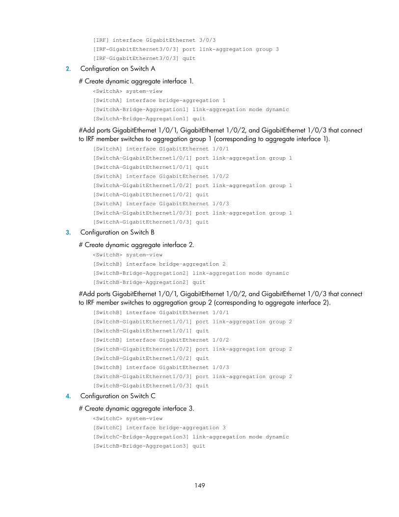
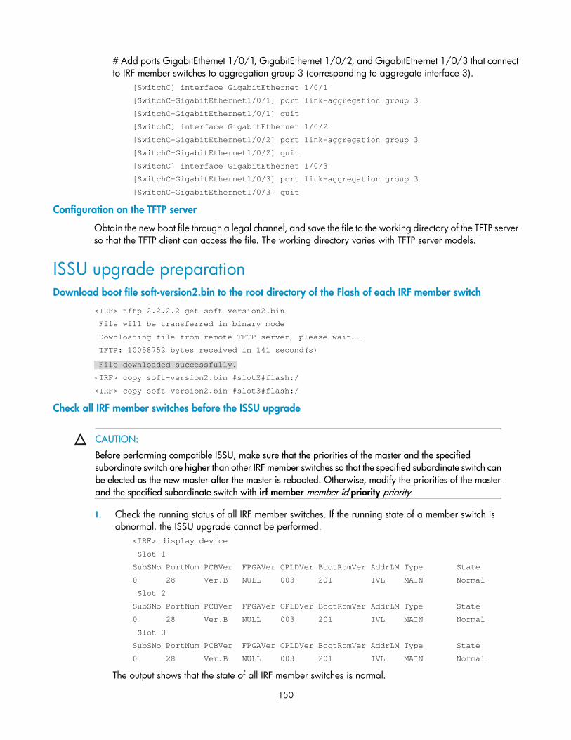
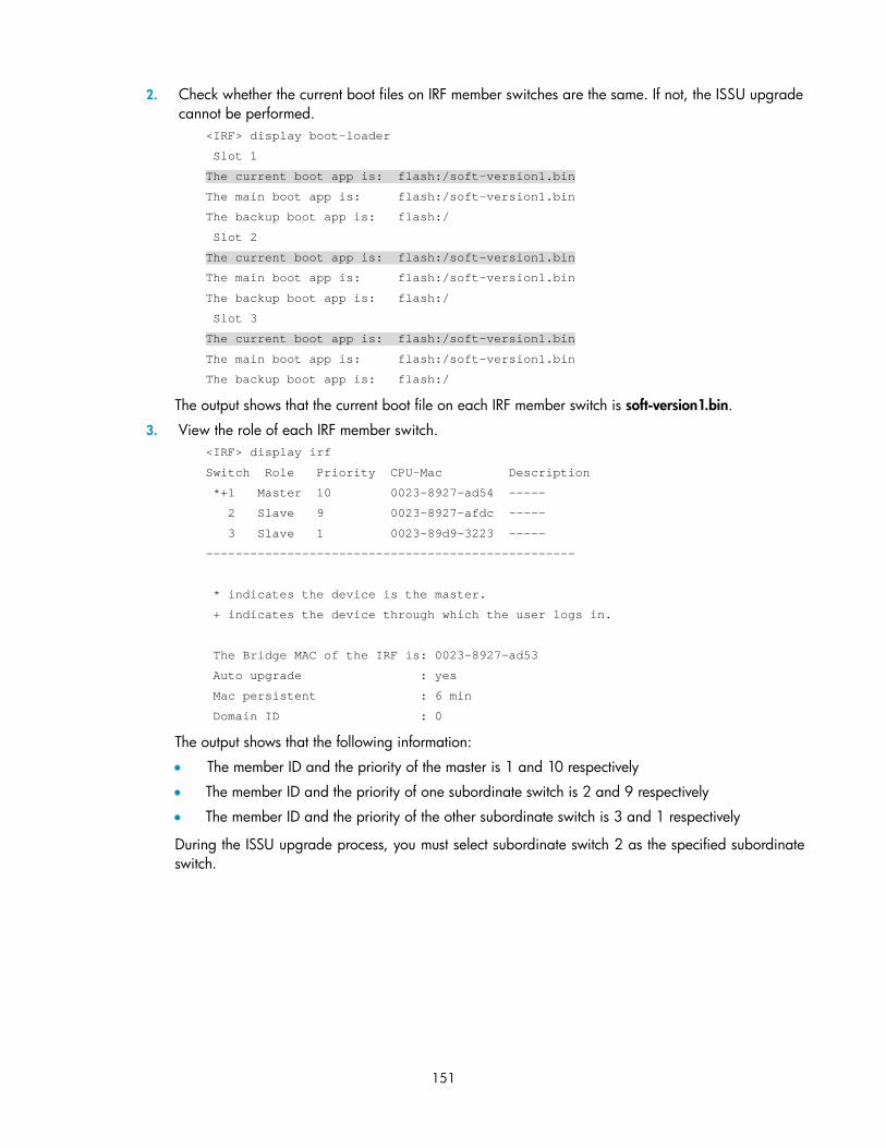
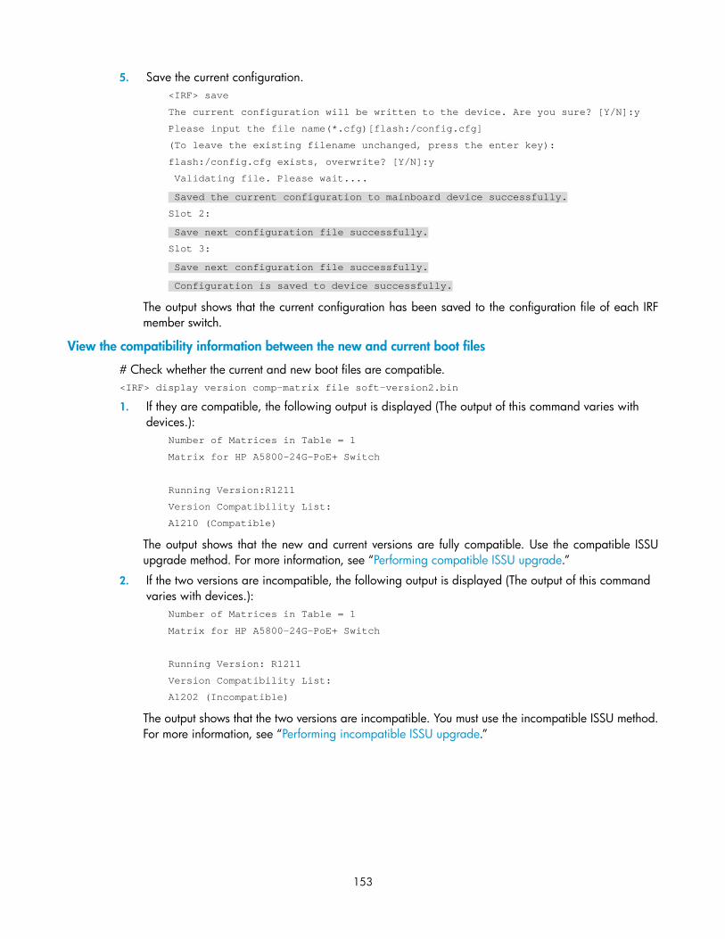
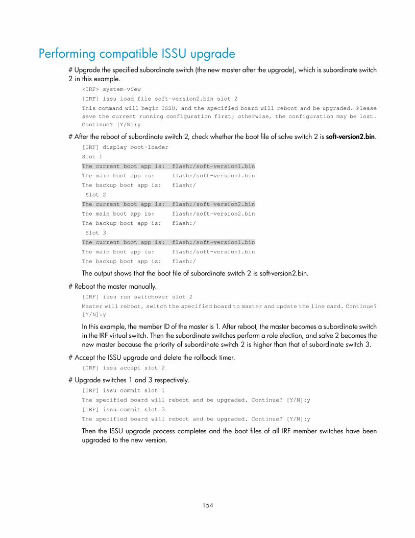
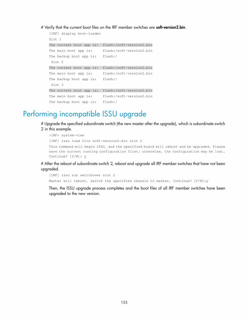
ISSU configuration example ······································································································································· 146 Current network status and requirements analysis ··························································································· 146 Configuration procedure ···································································································································· 148 ISSU upgrade preparation ································································································································· 150 Performing compatible ISSU upgrade ··············································································································· 154 Performing incompatible ISSU upgrade ··········································································································· 155
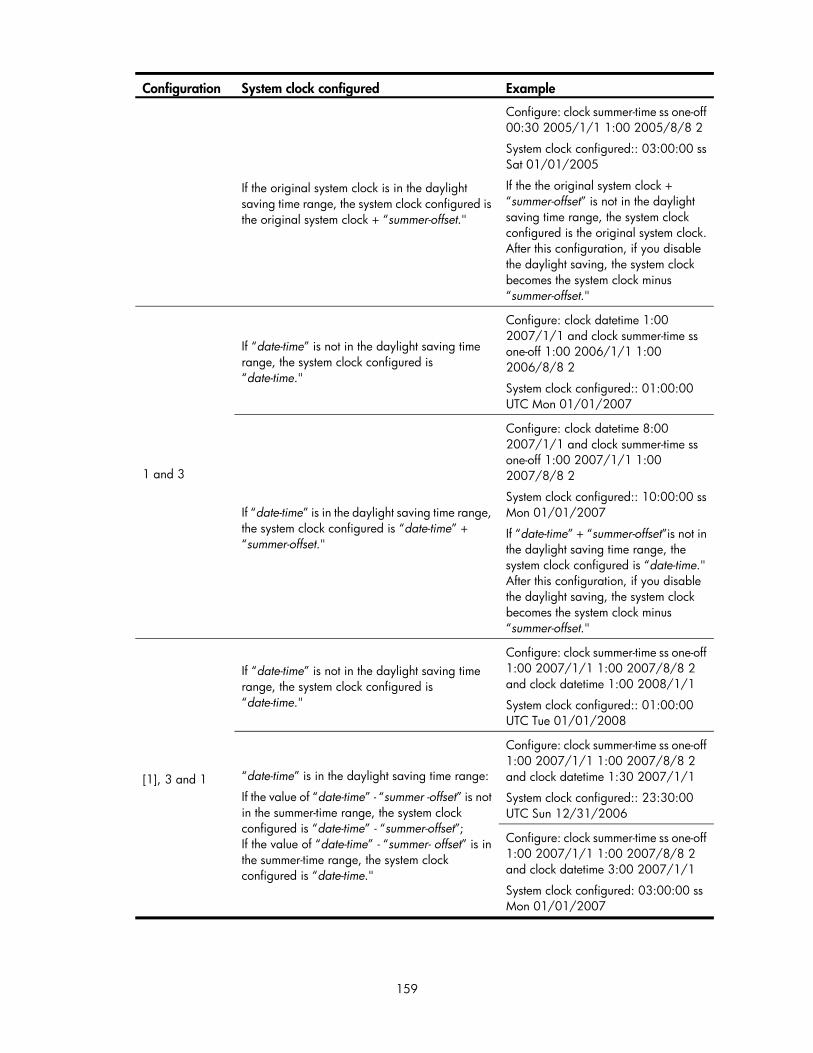
Configuring device management··························································································································· 157 Overview······································································································································································· 157 Configuring the device name ····································································································································· 157 Configuring the system clock ······································································································································ 157
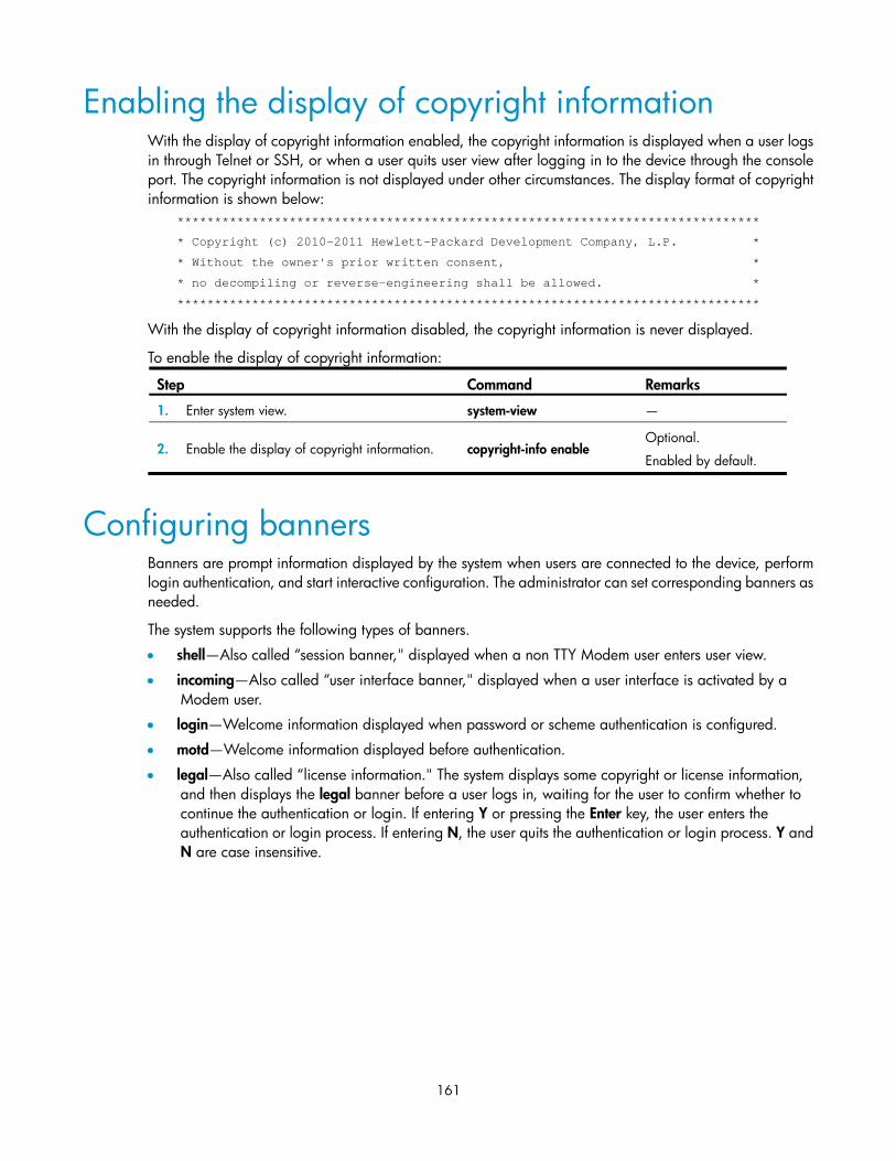
Displaying the system clock ······························································································································· 158 Enabling the display of copyright information ·········································································································· 161 Configuring banners ···················································································································································· 161
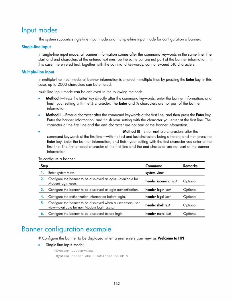
Input modes ·························································································································································· 162 Banner configuration example ··························································································································· 162
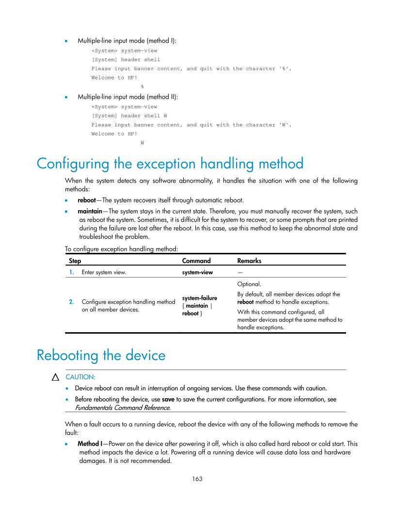
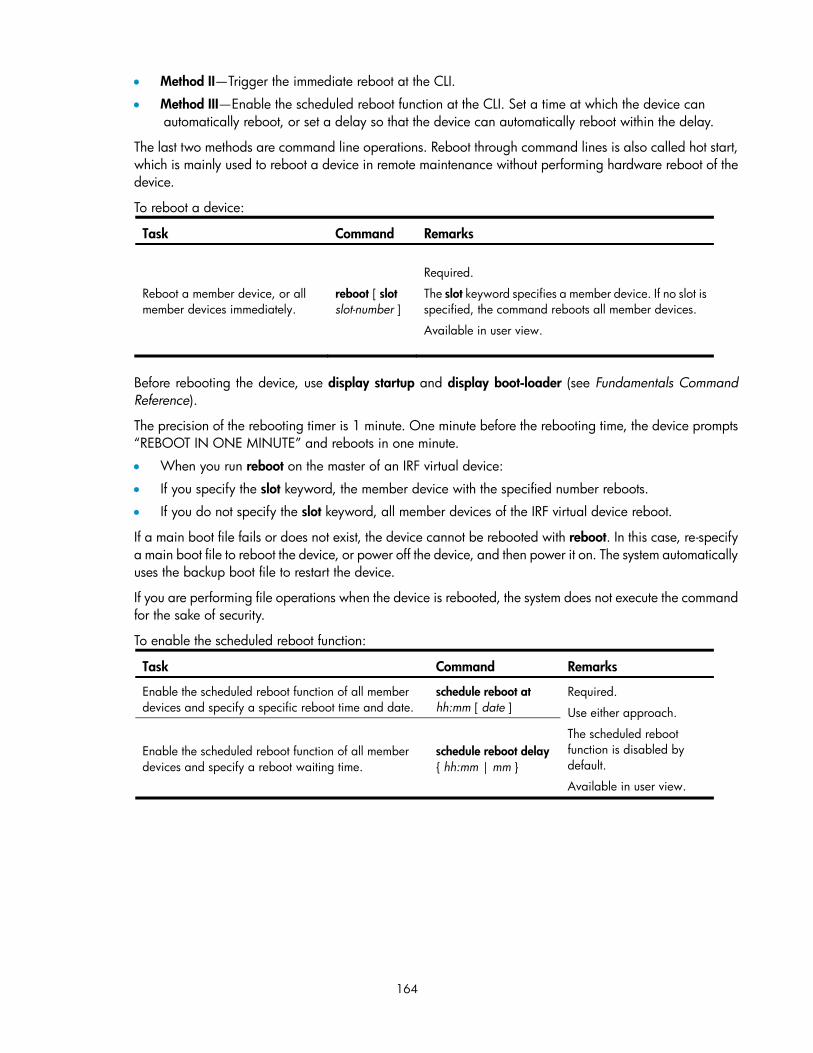
Configuring the exception handling method ············································································································ 163 Rebooting the device ··················································································································································· 163 Configuring scheduled tasks ······································································································································· 165
Configuring a scheduled task—Approach 1 ··································································································· 165
vii
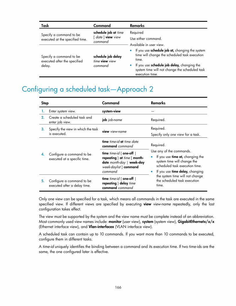
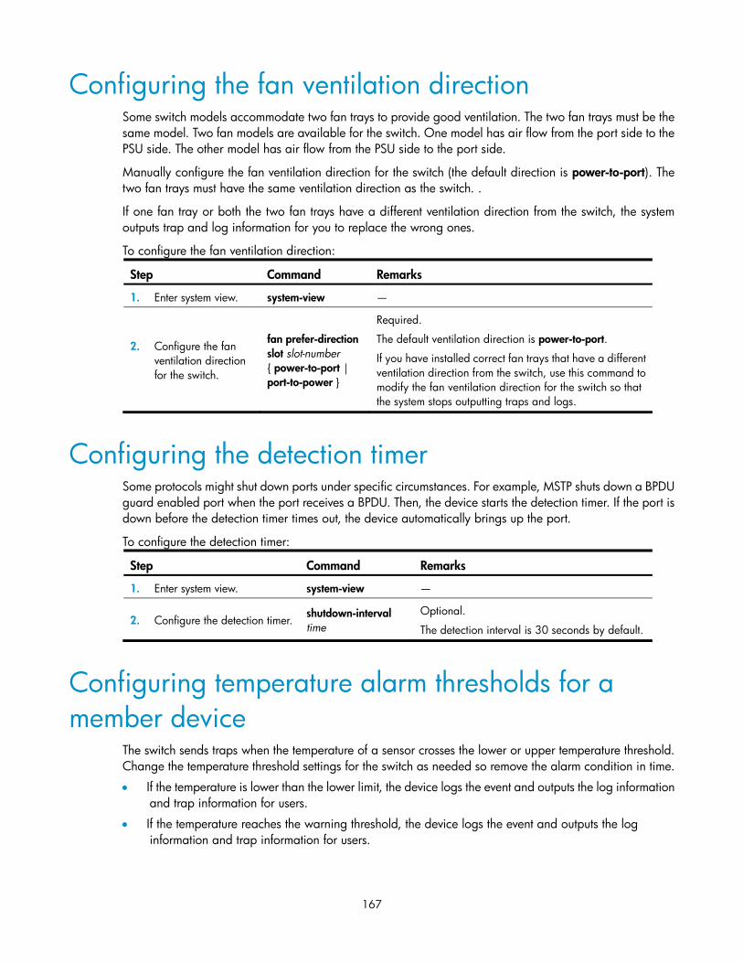
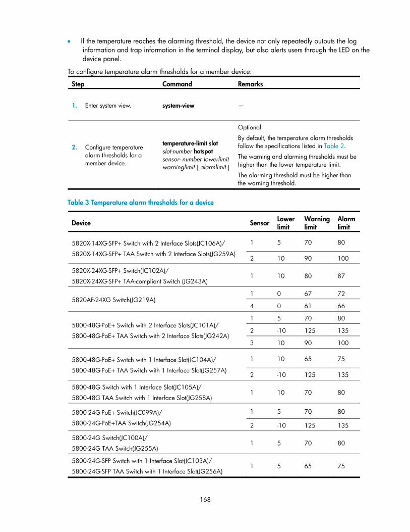
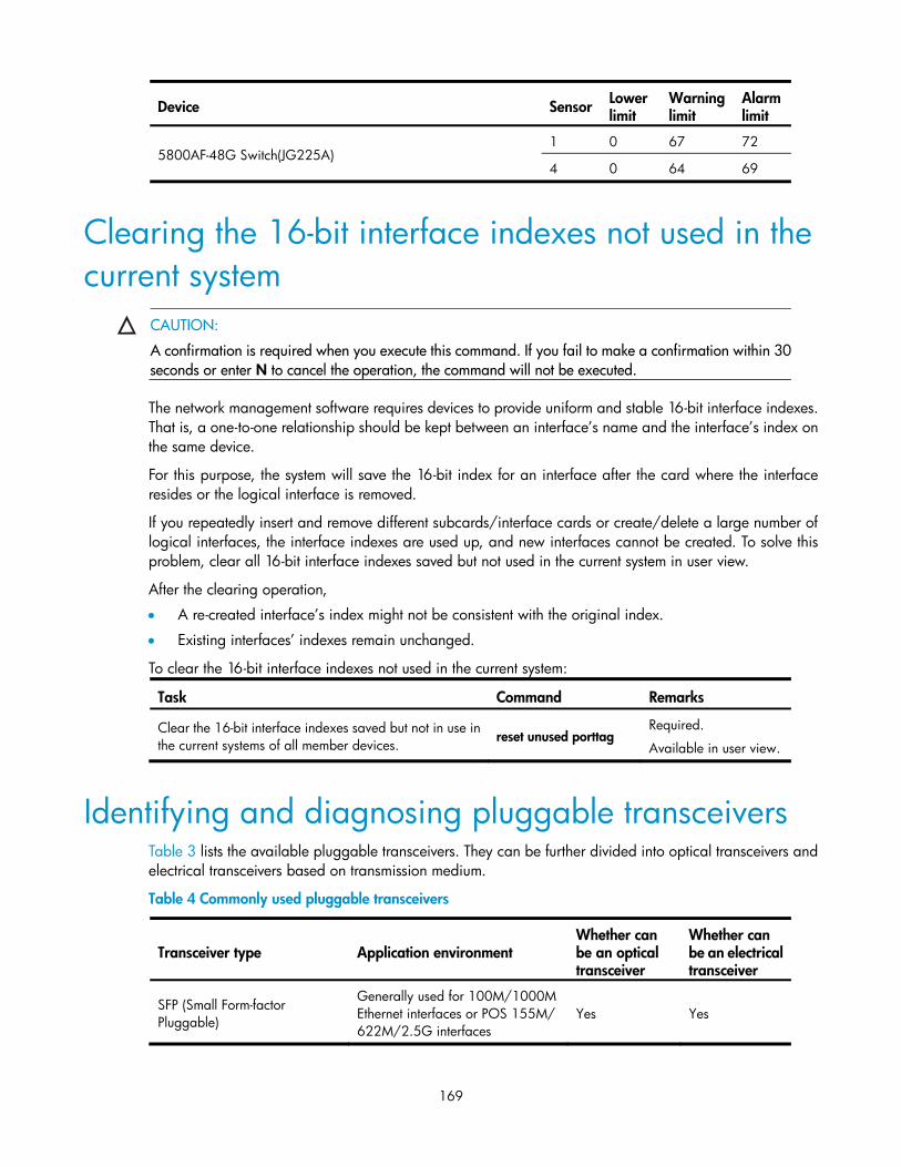
Configuring a scheduled task—Approach 2 ··································································································· 166 Configuring the fan ventilation direction ··················································································································· 167 Configuring the detection timer ·································································································································· 167 Configuring temperature alarm thresholds for a member device ··········································································· 167 Clearing the 16-bit interface indexes not used in the current system ····································································· 169 Identifying and diagnosing pluggable transceivers ································································································· 169
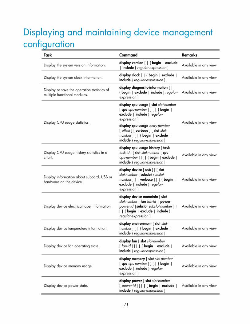
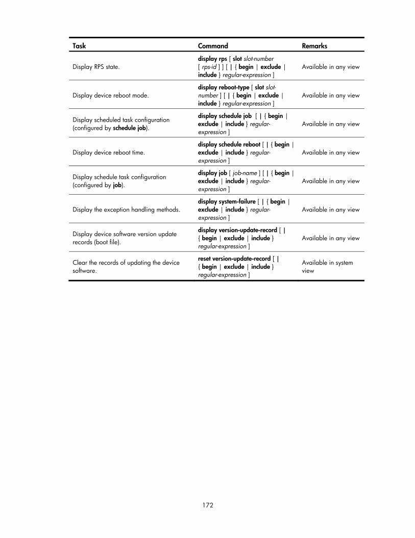
Displaying and maintaining device management configuration ············································································ 171
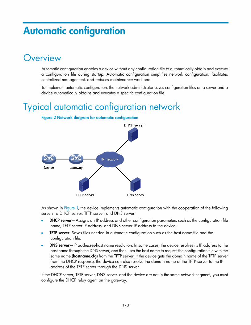
Automatic configuration ········································································································································· 173 Overview······································································································································································· 173 Typical automatic configuration network ·················································································································· 173 How automatic configuration works ·························································································································· 174
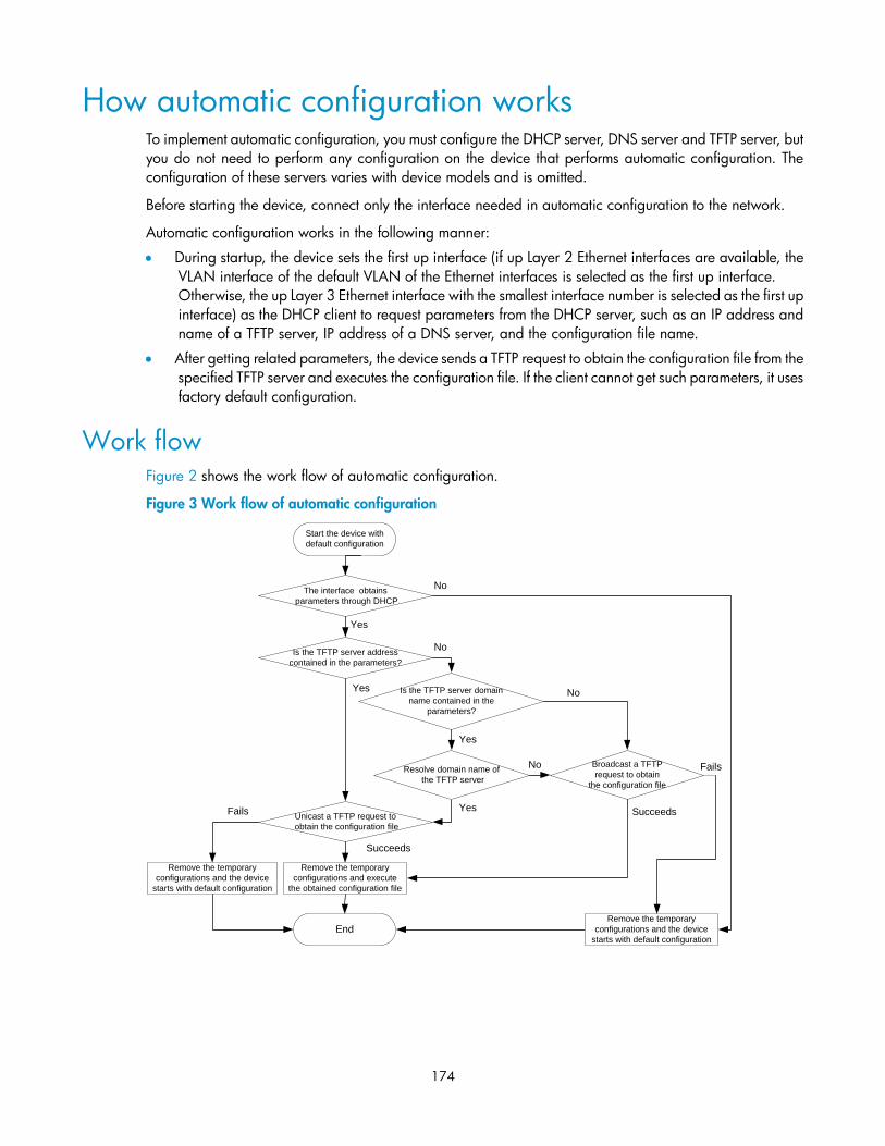
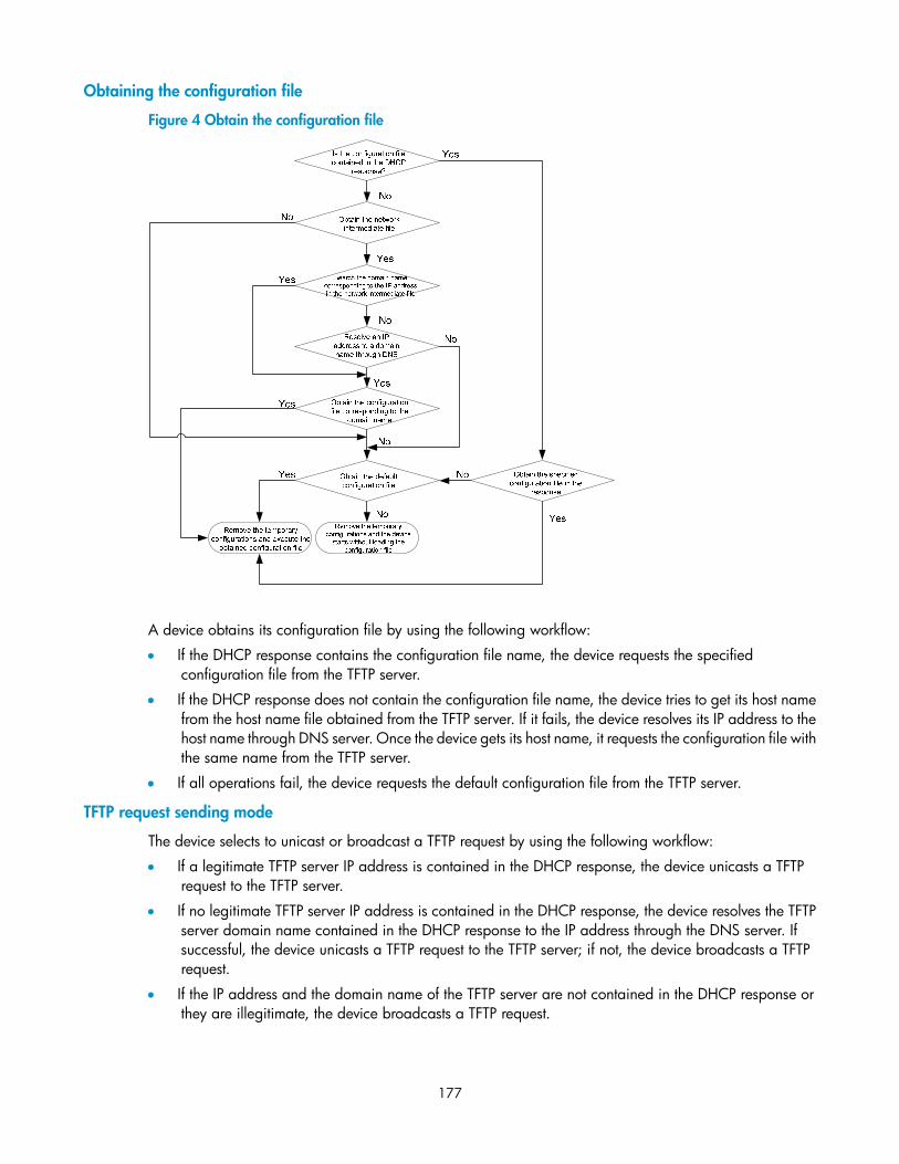
Work flow ···························································································································································· 174 Using DHCP to obtain an IP address and other configuration information ·················································· 175 Obtaining the configuration file from the TFTP server ····················································································· 176 Executing the configuration file ·························································································································· 178
Support and other resources ·································································································································· 179 Contacting HP ······························································································································································ 179
Subscription service ············································································································································ 179 Related information ······················································································································································ 179
Index ········································································································································································ 182
1
Configuring the CLI
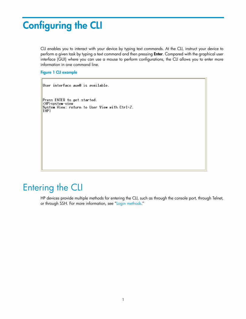
CLI enables you to interact with your device by typing text commands. At the CLI, instruct your device to perform a given task by typing a text command and then pressing Enter. Compared with the graphical user interface (GUI) where you can use a mouse to perform configurations, the CLI allows you to enter more information in one command line.
Figure 1 CLI example
Entering the CLI HP devices provide multiple methods for entering the CLI, such as through the console port, through Telnet, or through SSH. For more information, see “Login methods.”
2
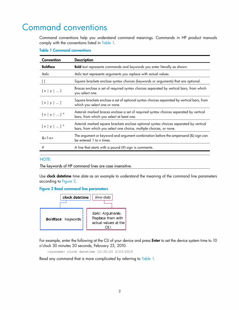
Command conventions Command conventions help you understand command meanings. Commands in HP product manuals comply with the conventions listed in Table 1.
Table 1 Command conventions
Convention Description
Boldface Bold text represents commands and keywords you enter literally as shown.
Italic Italic text represents arguments you replace with actual values.
[ ] Square brackets enclose syntax choices (keywords or arguments) that are optional.
{ x | y | ... } Braces enclose a set of required syntax choices separated by vertical bars, from which you select one.
[ x | y | ... ] Square brackets enclose a set of optional syntax choices separated by vertical bars, from which you select one or none.
{ x | y | ... } * Asterisk marked braces enclose a set of required syntax choices separated by vertical bars, from which you select at least one.
[ x | y | ... ] * Asterisk marked square brackets enclose optional syntax choices separated by vertical bars, from which you select one choice, multiple choices, or none.
&<1-n> The argument or keyword and argument combination before the ampersand (&) sign can be entered 1 to n times.
# A line that starts with a pound (#) sign is comments.
NOTE:
The keywords of HP command lines are case insensitive.
Use clock datetime time date as an example to understand the meaning of the command line parameters according to Figure 2.
Figure 2 Read command line parameters
For example, enter the following at the CLI of your device and press Enter to set the device system time to 10 o’clock 30 minutes 20 seconds, February 23, 2010.
<sysname> clock datetime 10:30:20 2/23/2010
Read any command that is more complicated by referring to Table 1.
3
Undo form of a command The undo form of a command restores the default, disables a function, or removes a configuration.
Almost all configuration commands have an undo form. For example, info-center enable enables the information center and undo info-center enable disables the information center.
CLI view description Commands are grouped into different classes by function. To use a command, you must enter the class view of the command.
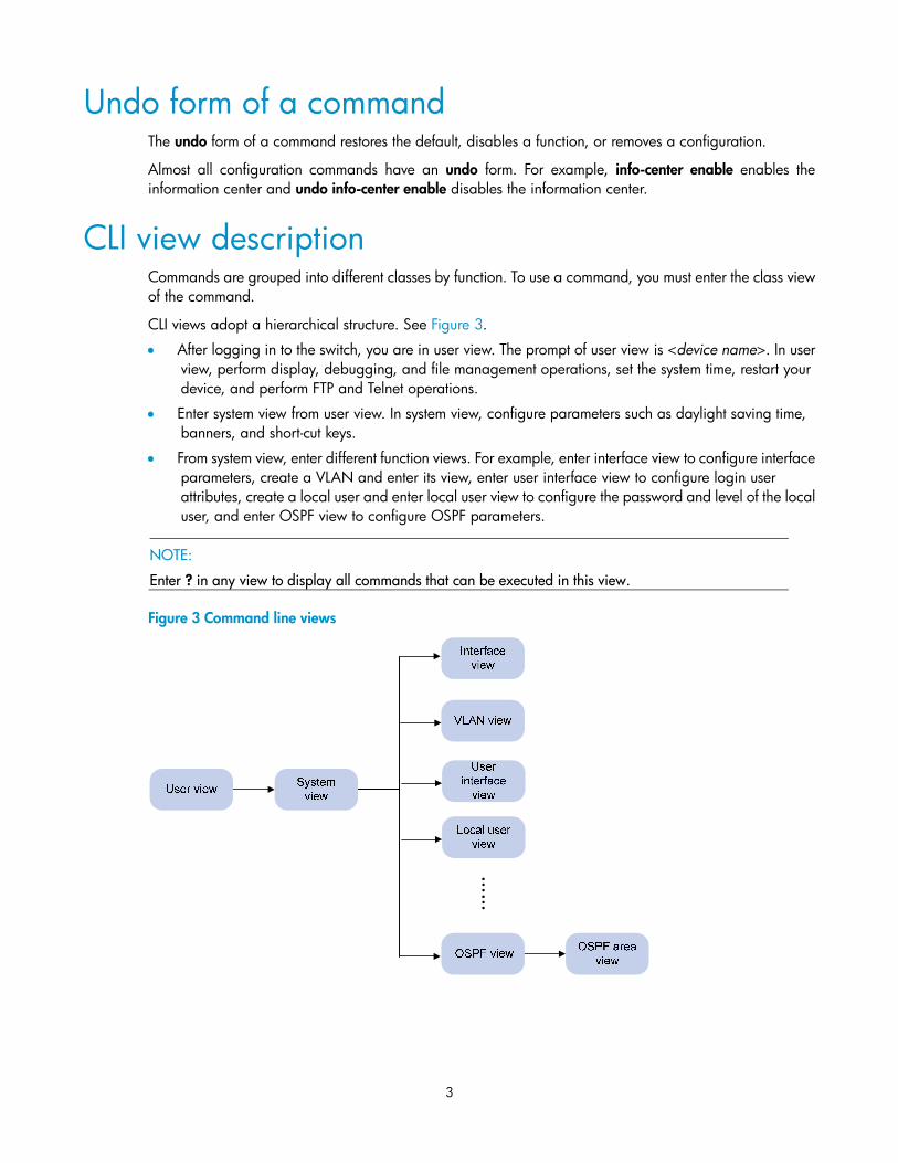
CLI views adopt a hierarchical structure. See Figure 3.
• After logging in to the switch, you are in user view. The prompt of user view is <device name>. In user view, perform display, debugging, and file management operations, set the system time, restart your device, and perform FTP and Telnet operations.
• Enter system view from user view. In system view, configure parameters such as daylight saving time, banners, and short-cut keys.
• From system view, enter different function views. For example, enter interface view to configure interface parameters, create a VLAN and enter its view, enter user interface view to configure login user attributes, create a local user and enter local user view to configure the password and level of the local user, and enter OSPF view to configure OSPF parameters.
NOTE:
Enter ? in any view to display all commands that can be executed in this view.
Figure 3 Command line views
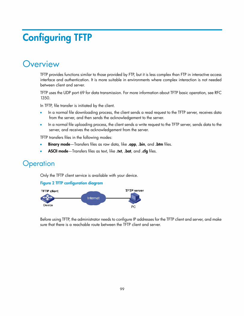
……
4
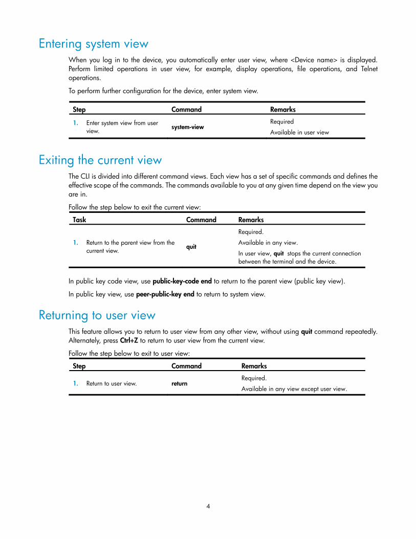
Entering system view When you log in to the device, you automatically enter user view, where <Device name> is displayed. Perform limited operations in user view, for example, display operations, file operations, and Telnet operations.
To perform further configuration for the device, enter system view.
Step Command Remarks
1. Enter system view from user view. system-view
Required
Available in user view
Exiting the current view The CLI is divided into different command views. Each view has a set of specific commands and defines the effective scope of the commands. The commands available to you at any given time depend on the view you are in.
Follow the step below to exit the current view:
Task Command Remarks
1. Return to the parent view from the current view.
quit
Required.
Available in any view.
In user view, quit stops the current connection between the terminal and the device.
In public key code view, use public-key-code end to return to the parent view (public key view).
In public key view, use peer-public-key end to return to system view.
Returning to user view This feature allows you to return to user view from any other view, without using quit command repeatedly. Alternately, press Ctrl+Z to return to user view from the current view.
Follow the step below to exit to user view:
Step Command Remarks
1. Return to user view. return Required.
Available in any view except user view.
5
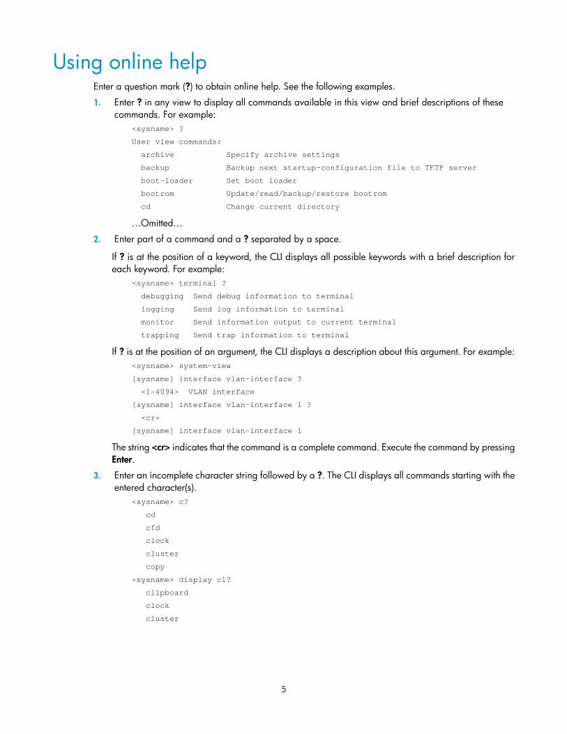
Using online help Enter a question mark (?) to obtain online help. See the following examples.
1. Enter ? in any view to display all commands available in this view and brief descriptions of these commands. For example:
<sysname> ?
User view commands:
archive Specify archive settings
backup Backup next startup-configuration file to TFTP server
boot-loader Set boot loader
bootrom Update/read/backup/restore bootrom
cd Change current directory
…Omitted…
2. Enter part of a command and a ? separated by a space.
If ? is at the position of a keyword, the CLI displays all possible keywords with a brief description for each keyword. For example:
<sysname> terminal ?
debugging Send debug information to terminal
logging Send log information to terminal
monitor Send information output to current terminal
trapping Send trap information to terminal
If ? is at the position of an argument, the CLI displays a description about this argument. For example: <sysname> system-view
[sysname] interface vlan-interface ?
<1-4094> VLAN interface
[sysname] interface vlan-interface 1 ?
<cr>
[sysname] interface vlan-interface 1
The string <cr> indicates that the command is a complete command. Execute the command by pressing Enter.
3. Enter an incomplete character string followed by a ?. The CLI displays all commands starting with the entered character(s).
<sysname> c?
cd
cfd
clock
cluster
copy
<sysname> display cl?
clipboard
clock
cluster
6
Entering commands
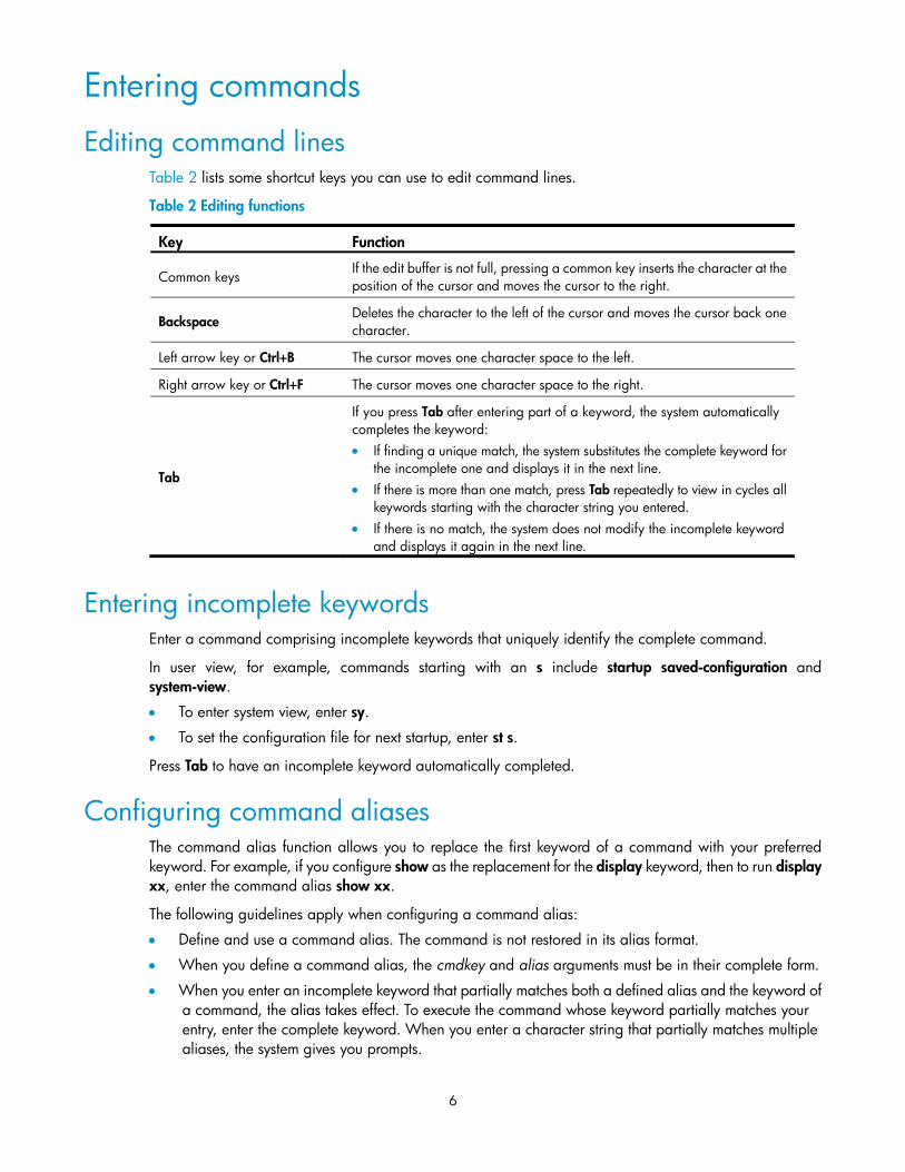
Editing command lines Table 2 lists some shortcut keys you can use to edit command lines.
Table 2 Editing functions
Key Function
Common keys If the edit buffer is not full, pressing a common key inserts the character at the position of the cursor and moves the cursor to the right.
Backspace Deletes the character to the left of the cursor and moves the cursor back one character.
Left arrow key or Ctrl+B The cursor moves one character space to the left.
Right arrow key or Ctrl+F The cursor moves one character space to the right.
Tab
If you press Tab after entering part of a keyword, the system automatically completes the keyword: • If finding a unique match, the system substitutes the complete keyword for
the incomplete one and displays it in the next line. • If there is more than one match, press Tab repeatedly to view in cycles all
keywords starting with the character string you entered. • If there is no match, the system does not modify the incomplete keyword
and displays it again in the next line.
Entering incomplete keywords Enter a command comprising incomplete keywords that uniquely identify the complete command.
In user view, for example, commands starting with an s include startup saved-configuration and system-view.
• To enter system view, enter sy.
• To set the configuration file for next startup, enter st s.
Press Tab to have an incomplete keyword automatically completed.
Configuring command aliases The command alias function allows you to replace the first keyword of a command with your preferred keyword. For example, if you configure show as the replacement for the display keyword, then to run display xx, enter the command alias show xx.
The following guidelines apply when configuring a command alias:
• Define and use a command alias. The command is not restored in its alias format.
• When you define a command alias, the cmdkey and alias arguments must be in their complete form.
• When you enter an incomplete keyword that partially matches both a defined alias and the keyword of a command, the alias takes effect. To execute the command whose keyword partially matches your entry, enter the complete keyword. When you enter a character string that partially matches multiple aliases, the system gives you prompts.
7
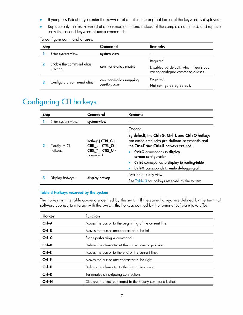
• If you press Tab after you enter the keyword of an alias, the original format of the keyword is displayed.
• Replace only the first keyword of a non-undo command instead of the complete command; and replace only the second keyword of undo commands.
To configure command aliases:
Step Command Remarks
1. Enter system view. system-view —
2. Enable the command alias function.
command-alias enable Required
Disabled by default, which means you cannot configure command aliases.
3. Configure a command alias. command-alias mapping cmdkey alias
By default, the Ctrl+G, Ctrl+L and Ctrl+O hotkeys are associated with pre-defined commands and the Ctrl+T and Ctrl+U hotkeys are not. • Ctrl+G corresponds to display
current-configuration. • Ctrl+L corresponds to display ip routing-table. • Ctrl+O corresponds to undo debugging all.
3. Display hotkeys. display hotkey Available in any view.
See Table 3 for hotkeys reserved by the system.
Table 3 Hotkeys reserved by the system
The hotkeys in this table above are defined by the switch. If the same hotkeys are defined by the terminal software you use to interact with the switch, the hotkeys defined by the terminal software take effect.
Hotkey Function
Ctrl+A Moves the cursor to the beginning of the current line.
Ctrl+B Moves the cursor one character to the left.
Ctrl+C Stops performing a command.
Ctrl+D Deletes the character at the current cursor position.
Ctrl+E Moves the cursor to the end of the current line.
Ctrl+F Moves the cursor one character to the right.
Ctrl+H Deletes the character to the left of the cursor.
Ctrl+K Terminates an outgoing connection.
Ctrl+N Displays the next command in the history command buffer.
8
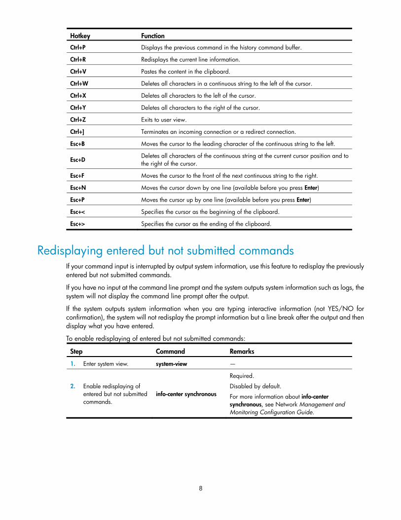
Hotkey Function
Ctrl+P Displays the previous command in the history command buffer.
Ctrl+R Redisplays the current line information.
Ctrl+V Pastes the content in the clipboard.
Ctrl+W Deletes all characters in a continuous string to the left of the cursor.
Ctrl+X Deletes all characters to the left of the cursor.
Ctrl+Y Deletes all characters to the right of the cursor.
Ctrl+Z Exits to user view.
Ctrl+] Terminates an incoming connection or a redirect connection.
Esc+B Moves the cursor to the leading character of the continuous string to the left.
Esc+D Deletes all characters of the continuous string at the current cursor position and to the right of the cursor.
Esc+F Moves the cursor to the front of the next continuous string to the right.
Esc+N Moves the cursor down by one line (available before you press Enter)
Esc+P Moves the cursor up by one line (available before you press Enter)
Esc+< Specifies the cursor as the beginning of the clipboard.
Esc+> Specifies the cursor as the ending of the clipboard.
Redisplaying entered but not submitted commands If your command input is interrupted by output system information, use this feature to redisplay the previously entered but not submitted commands.
If you have no input at the command line prompt and the system outputs system information such as logs, the system will not display the command line prompt after the output.
If the system outputs system information when you are typing interactive information (not YES/NO for confirmation), the system will not redisplay the prompt information but a line break after the output and then display what you have entered.
To enable redisplaying of entered but not submitted commands:
Step Command Remarks
1. Enter system view. system-view —
2. Enable redisplaying of entered but not submitted commands.
info-center synchronous
Required.
Disabled by default.
For more information about info-center synchronous, see Network Management and Monitoring Configuration Guide.
9
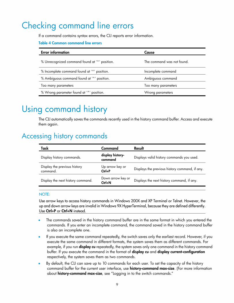
Checking command line errors If a command contains syntax errors, the CLI reports error information.
Table 4 Common command line errors
Error information Cause
% Unrecognized command found at '^' position. The command was not found.
% Incomplete command found at '^' position. Incomplete command
% Ambiguous command found at '^' position. Ambiguous command
Too many parameters Too many parameters
% Wrong parameter found at '^' position. Wrong parameters
Using command history The CLI automatically saves the commands recently used in the history command buffer. Access and execute them again.
Accessing history commands
Task Command Result
Display history commands. display history- command
Displays valid history commands you used.
Display the previous history command.
Up arrow key or Ctrl+P
Displays the previous history command, if any.
Display the next history command. Down arrow key or Ctrl+N
Displays the next history command, if any.
NOTE:
Use arrow keys to access history commands in Windows 200X and XP Terminal or Telnet. However, theup and down arrow keys are invalid in Windows 9X HyperTerminal, because they are defined differently.Use Ctrl+P or Ctrl+N instead.
• The commands saved in the history command buffer are in the same format in which you entered the commands. If you enter an incomplete command, the command saved in the history command buffer is also an incomplete one.
• If you execute the same command repeatedly, the switch saves only the earliest record. However, if you execute the same command in different formats, the system saves them as different commands. For example, if you run display cu repeatedly, the system saves only one command in the history command buffer. If you execute the command in the format of display cu and display current-configuration respectively, the system saves them as two commands.
• By default, the CLI can save up to 10 commands for each user. To set the capacity of the history command buffer for the current user interface, use history-command max-size. (For more information about history-command max-size, see “Logging in to the switch commands.”
10
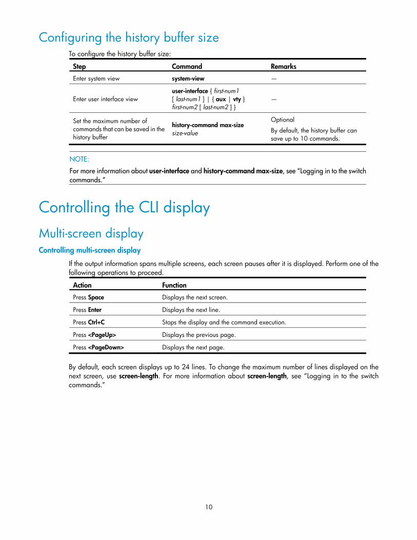
Configuring the history buffer size To configure the history buffer size:
Step Command Remarks
Enter system view system-view —
Enter user interface view user-interface { first-num1 [ last-num1 ] | { aux | vty } first-num2 [ last-num2 ] }
—
Set the maximum number of commands that can be saved in the history buffer
history-command max-size size-value
Optional
By default, the history buffer can save up to 10 commands.
NOTE:
For more information about user-interface and history-command max-size, see “Logging in to the switchcommands.”
If the output information spans multiple screens, each screen pauses after it is displayed. Perform one of the following operations to proceed.
Action Function
Press Space Displays the next screen.
Press Enter Displays the next line.
Press Ctrl+C Stops the display and the command execution.
Press <PageUp> Displays the previous page.
Press <PageDown> Displays the next page.
By default, each screen displays up to 24 lines. To change the maximum number of lines displayed on the next screen, use screen-length. For more information about screen-length, see “Logging in to the switch commands.”
11
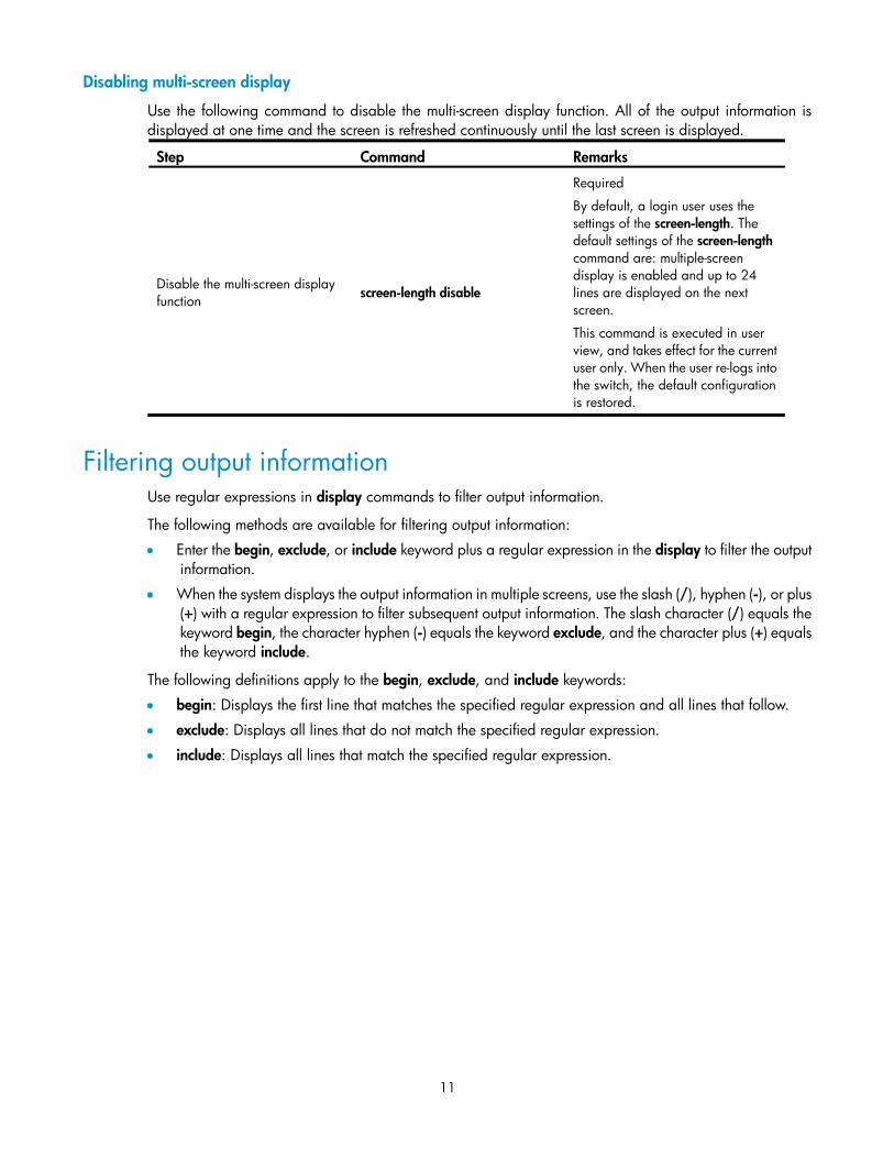
Disabling multi-screen display
Use the following command to disable the multi-screen display function. All of the output information is displayed at one time and the screen is refreshed continuously until the last screen is displayed.
Step Command Remarks
Disable the multi-screen display function screen-length disable
Required
By default, a login user uses the settings of the screen-length. The default settings of the screen-length command are: multiple-screen display is enabled and up to 24 lines are displayed on the next screen.
This command is executed in user view, and takes effect for the current user only. When the user re-logs into the switch, the default configuration is restored.
Filtering output information Use regular expressions in display commands to filter output information.
The following methods are available for filtering output information:
• Enter the begin, exclude, or include keyword plus a regular expression in the display to filter the output information.
• When the system displays the output information in multiple screens, use the slash (/), hyphen (-), or plus (+) with a regular expression to filter subsequent output information. The slash character (/) equals the keyword begin, the character hyphen (-) equals the keyword exclude, and the character plus (+) equals the keyword include.
The following definitions apply to the begin, exclude, and include keywords:
• begin: Displays the first line that matches the specified regular expression and all lines that follow.
• exclude: Displays all lines that do not match the specified regular expression.
• include: Displays all lines that match the specified regular expression.
12
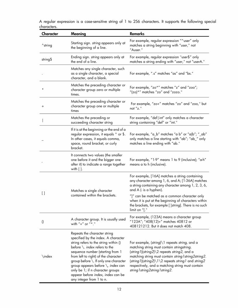
A regular expression is a case-sensitive string of 1 to 256 characters. It supports the following special characters.
Character Meaning Remarks
^string Starting sign. string appears only at the beginning of a line.
For example, regular expression “^user” only matches a string beginning with “user," not “Auser."
string$ Ending sign. string appears only at the end of a line.
For example, regular expression "user$” only matches a string ending with “user," not “userA."
. Matches any single character, such as a single character, a special character, and a blank.
For example, “.s” matches “as” and “bs."
* Matches the preceding character or character group zero or multiple times.
For example, “zo*” matches “z” and “zoo”; “(zo)*” matches “zo” and “zozo."
+ Matches the preceding character or character group one or multiple times
For example, “zo+” matches “zo” and “zoo," but not “z."
| Matches the preceding or succeeding character string
For example, “def|int” only matches a character string containing “def” or “int."
_
If it is at the beginning or the end of a regular expression, it equals ^ or $. In other cases, it equals comma, space, round bracket, or curly bracket.
For example, “a_b” matches “a b” or “a(b”; “_ab” only matches a line starting with “ab”; “ab_” only matches a line ending with “ab."
-
It connects two values (the smaller one before it and the bigger one after it) to indicate a range together with [ ].
For example, “1-9” means 1 to 9 (inclusive); “a-h” means a to h (inclusive).
[ ] Matches a single character contained within the brackets.
For example, [16A] matches a string containing any character among 1, 6, and A; [1-36A] matches a string containing any character among 1, 2, 3, 6, and A (- is a hyphen).
“]” can be matched as a common character only when it is put at the beginning of characters within the brackets, for example [ ]string]. There is no such limit on “[."
() A character group. It is usually used with “+” or “*."
For example, (123A) means a character group “123A”; “408(12)+” matches 40812 or 408121212. But it does not match 408.
\index
Repeats the character string specified by the index. A character string refers to the string within () before \. index refers to the sequence number (starting from 1 from left to right) of the character group before \. If only one character group appears before \, index can only be 1; if n character groups appear before index, index can be any integer from 1 to n.
For example, (string)\1 repeats string, and a matching string must contain stringstring. (string1)(string2)\2 repeats string2, and a matching string must contain string1string2string2. (string1)(string2)\1\2 repeats string1 and string2 respectively, and a matching string must contain string1string2string1string2.
13
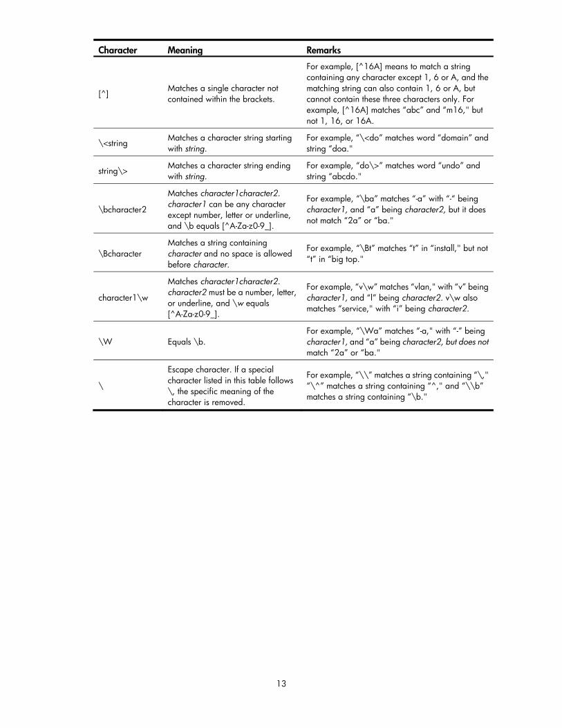
Character Meaning Remarks
[^] Matches a single character not contained within the brackets.
For example, [^16A] means to match a string containing any character except 1, 6 or A, and the matching string can also contain 1, 6 or A, but cannot contain these three characters only. For example, [^16A] matches “abc” and “m16," but not 1, 16, or 16A.
\<string Matches a character string starting with string.
For example, “\<do” matches word “domain” and string “doa."
string\> Matches a character string ending with string.
For example, “do\>” matches word “undo” and string “abcdo."
\bcharacter2
Matches character1character2. character1 can be any character except number, letter or underline, and \b equals [^A-Za-z0-9_].
For example, “\ba” matches “-a” with “-“ being character1, and “a” being character2, but it does not match “2a” or “ba."
\Bcharacter Matches a string containing character and no space is allowed before character.
For example, “\Bt” matches “t” in “install," but not “t” in “big top."
character1\w
Matches character1character2. character2 must be a number, letter, or underline, and \w equals [^A-Za-z0-9_].
For example, “v\w” matches “vlan," with “v” being character1, and “l” being character2. v\w also matches “service," with “i” being character2.
\W Equals \b. For example, “\Wa” matches “-a," with “-” being character1, and “a” being character2, but does not match “2a” or “ba."
\
Escape character. If a special character listed in this table follows \, the specific meaning of the character is removed.
For example, “\\” matches a string containing “\," “\^” matches a string containing “^," and “\\b” matches a string containing “\b."
14
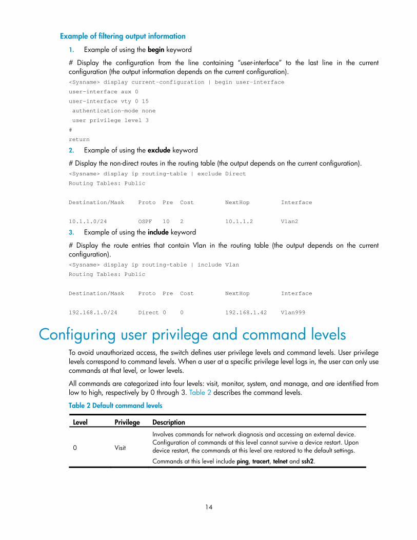
Example of filtering output information
1. Example of using the begin keyword
# Display the configuration from the line containing “user-interface” to the last line in the current configuration (the output information depends on the current configuration). <Sysname> display current-configuration | begin user-interface
user-interface aux 0
user-interface vty 0 15
authentication-mode none
user privilege level 3
#
return
2. Example of using the exclude keyword
# Display the non-direct routes in the routing table (the output depends on the current configuration). <Sysname> display ip routing-table | exclude Direct
Routing Tables: Public
Destination/Mask Proto Pre Cost NextHop Interface
10.1.1.0/24 OSPF 10 2 10.1.1.2 Vlan2
3. Example of using the include keyword
# Display the route entries that contain Vlan in the routing table (the output depends on the current configuration). <Sysname> display ip routing-table | include Vlan
Routing Tables: Public
Destination/Mask Proto Pre Cost NextHop Interface
192.168.1.0/24 Direct 0 0 192.168.1.42 Vlan999
Configuring user privilege and command levels To avoid unauthorized access, the switch defines user privilege levels and command levels. User privilege levels correspond to command levels. When a user at a specific privilege level logs in, the user can only use commands at that level, or lower levels.
All commands are categorized into four levels: visit, monitor, system, and manage, and are identified from low to high, respectively by 0 through 3. Table 2 describes the command levels.
Table 2 Default command levels
Level Privilege Description
0 Visit
Involves commands for network diagnosis and accessing an external device. Configuration of commands at this level cannot survive a device restart. Upon device restart, the commands at this level are restored to the default settings.
Commands at this level include ping, tracert, telnet and ssh2.
15
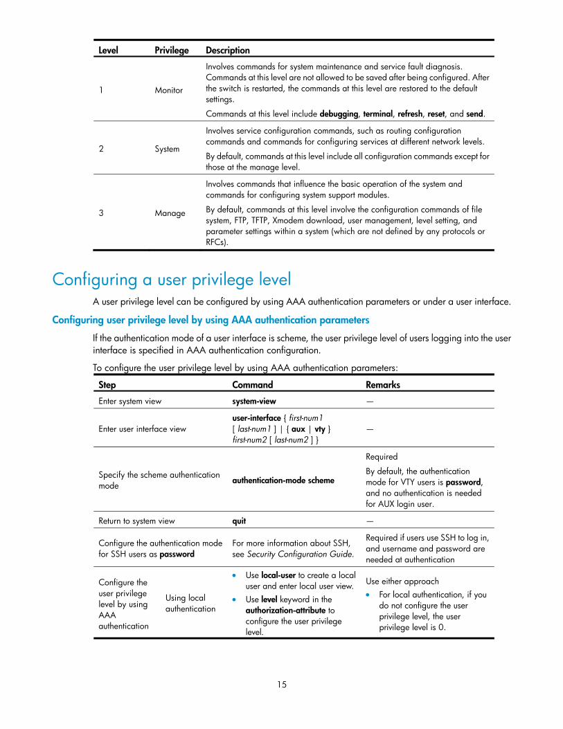
Level Privilege Description
1 Monitor
Involves commands for system maintenance and service fault diagnosis. Commands at this level are not allowed to be saved after being configured. After the switch is restarted, the commands at this level are restored to the default settings.
Commands at this level include debugging, terminal, refresh, reset, and send.
2 System
Involves service configuration commands, such as routing configuration commands and commands for configuring services at different network levels.
By default, commands at this level include all configuration commands except for those at the manage level.
3 Manage
Involves commands that influence the basic operation of the system and commands for configuring system support modules.
By default, commands at this level involve the configuration commands of file system, FTP, TFTP, Xmodem download, user management, level setting, and parameter settings within a system (which are not defined by any protocols or RFCs).
Configuring a user privilege level A user privilege level can be configured by using AAA authentication parameters or under a user interface.
Configuring user privilege level by using AAA authentication parameters
If the authentication mode of a user interface is scheme, the user privilege level of users logging into the user interface is specified in AAA authentication configuration.
To configure the user privilege level by using AAA authentication parameters:
Step Command Remarks
Enter system view system-view —
Enter user interface view user-interface { first-num1 [ last-num1 ] | { aux | vty } first-num2 [ last-num2 ] }
—
Specify the scheme authentication mode authentication-mode scheme
Required
By default, the authentication mode for VTY users is password, and no authentication is needed for AUX login user.
Return to system view quit —
Configure the authentication mode for SSH users as password
For more information about SSH, see Security Configuration Guide.
Required if users use SSH to log in, and username and password are needed at authentication
Configure the user privilege level by using AAA authentication
Using local authentication
• Use local-user to create a local user and enter local user view.
• Use level keyword in the authorization-attribute to configure the user privilege level.
Use either approach • For local authentication, if you
do not configure the user privilege level, the user privilege level is 0.
16
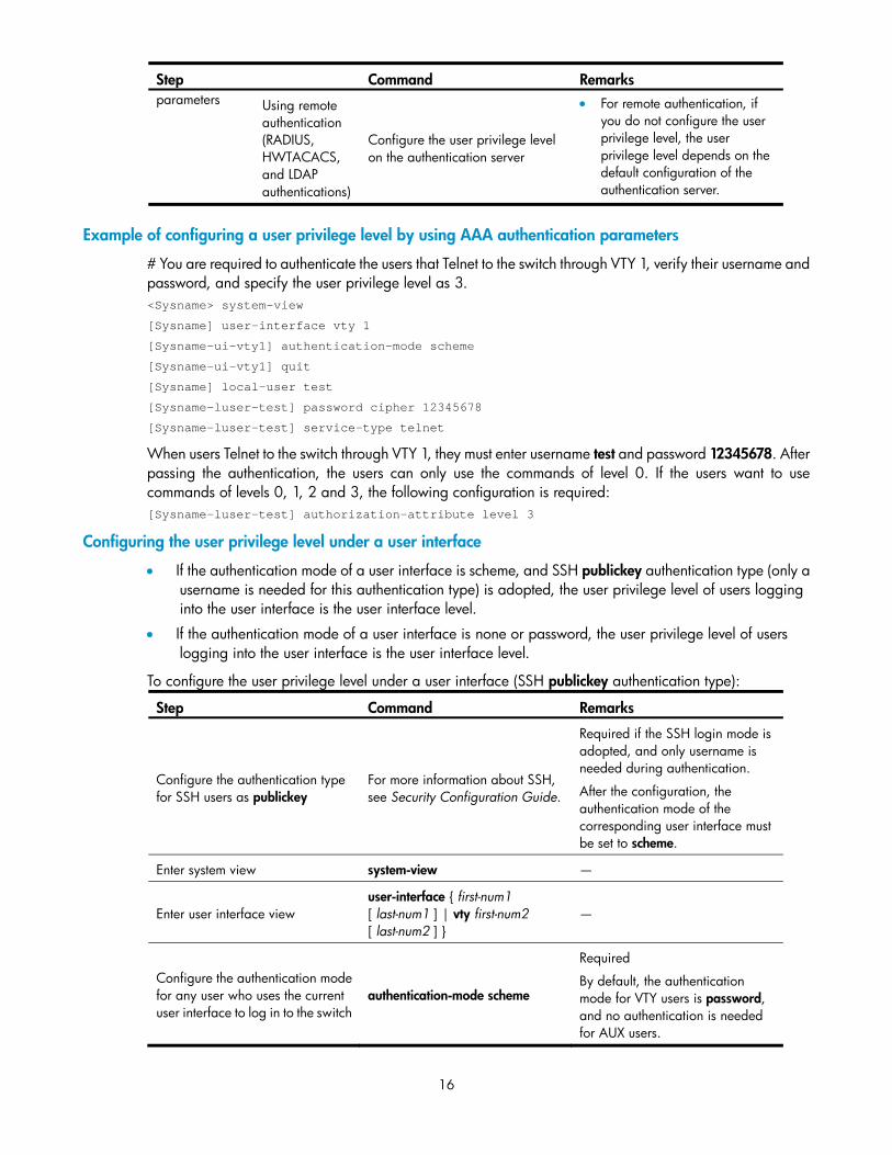
Step Command Remarks parameters Using remote
authentication (RADIUS, HWTACACS, and LDAP authentications)
Configure the user privilege level on the authentication server
• For remote authentication, if you do not configure the user privilege level, the user privilege level depends on the default configuration of the authentication server.
Example of configuring a user privilege level by using AAA authentication parameters
# You are required to authenticate the users that Telnet to the switch through VTY 1, verify their username and password, and specify the user privilege level as 3. <Sysname> system-view
[Sysname] user-interface vty 1
[Sysname-ui-vty1] authentication-mode scheme
[Sysname-ui-vty1] quit
[Sysname] local-user test
[Sysname-luser-test] password cipher 12345678
[Sysname-luser-test] service-type telnet
When users Telnet to the switch through VTY 1, they must enter username test and password 12345678. After passing the authentication, the users can only use the commands of level 0. If the users want to use commands of levels 0, 1, 2 and 3, the following configuration is required: [Sysname-luser-test] authorization-attribute level 3
Configuring the user privilege level under a user interface
• If the authentication mode of a user interface is scheme, and SSH publickey authentication type (only a username is needed for this authentication type) is adopted, the user privilege level of users logging into the user interface is the user interface level.
• If the authentication mode of a user interface is none or password, the user privilege level of users logging into the user interface is the user interface level.
To configure the user privilege level under a user interface (SSH publickey authentication type):
Step Command Remarks
Configure the authentication type for SSH users as publickey
For more information about SSH, see Security Configuration Guide.
Required if the SSH login mode is adopted, and only username is needed during authentication.
After the configuration, the authentication mode of the corresponding user interface must be set to scheme.
Enter system view system-view —
Enter user interface view user-interface { first-num1 [ last-num1 ] | vty first-num2 [ last-num2 ] }
—
Configure the authentication mode for any user who uses the current user interface to log in to the switch
authentication-mode scheme
Required
By default, the authentication mode for VTY users is password, and no authentication is needed for AUX users.
17
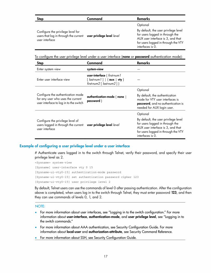
Step Command Remarks
Configure the privilege level for users that log in through the current user interface
user privilege level level
Optional
By default, the user privilege level for users logged in through the AUX user interface is 3, and that for users logged in through the VTY interfaces is 0.
To configure the user privilege level under a user interface (none or password authentication mode):
Step Command Remarks
Enter system view system-view —
Enter user interface view user-interface { first-num1 [ last-num1 ] | { aux | vty } first-num2 [ last-num2 ] }
—
Configure the authentication mode for any user who uses the current user interface to log in to the switch
authentication-mode { none | password }
Optional
By default, the authentication mode for VTY user interfaces is password, and no authentication is needed for AUX login user.
Configure the privilege level of users logged in through the current user interface
user privilege level level
Optional
By default, the user privilege level for users logged in through the AUX user interface is 3, and that for users logged in through the VTY interfaces is 0.
Example of configuring a user privilege level under a user interface
# Authenticate users logged in to the switch through Telnet, verify their password, and specify their user privilege level as 2. <Sysname> system-view
[Sysname] user-interface vty 0 15
[Sysname-ui-vty0-15] authentication-mode password
[Sysname-ui-vty0-15] set authentication password cipher 123
[Sysname-ui-vty0-15] user privilege level 2
By default, Telnet users can use the commands of level 0 after passing authentication. After the configuration above is completed, when users log in to the switch through Telnet, they must enter password 123, and then they can use commands of levels 0, 1, and 2.
NOTE:
• For more information about user interfaces, see “Logging in to the switch configuration.” For more information about user-interface, authentication-mode, and user privilege level, see “Logging in to the switch commands.”
• For more information about AAA authentication, see Security Configuration Guide. For more information about local-user and authorization-attribute, see Security Command Reference.
• For more information about SSH, see Security Configuration Guide.
18
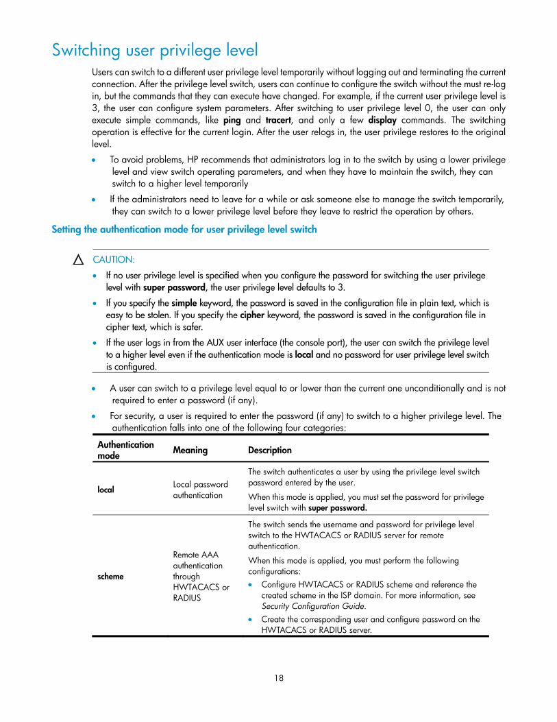
Switching user privilege level Users can switch to a different user privilege level temporarily without logging out and terminating the current connection. After the privilege level switch, users can continue to configure the switch without the must re-log in, but the commands that they can execute have changed. For example, if the current user privilege level is 3, the user can configure system parameters. After switching to user privilege level 0, the user can only execute simple commands, like ping and tracert, and only a few display commands. The switching operation is effective for the current login. After the user relogs in, the user privilege restores to the original level.
• To avoid problems, HP recommends that administrators log in to the switch by using a lower privilege level and view switch operating parameters, and when they have to maintain the switch, they can switch to a higher level temporarily
• If the administrators need to leave for a while or ask someone else to manage the switch temporarily, they can switch to a lower privilege level before they leave to restrict the operation by others.
Setting the authentication mode for user privilege level switch
CAUTION:
• If no user privilege level is specified when you configure the password for switching the user privilege level with super password, the user privilege level defaults to 3.
• If you specify the simple keyword, the password is saved in the configuration file in plain text, which is easy to be stolen. If you specify the cipher keyword, the password is saved in the configuration file in cipher text, which is safer.
• If the user logs in from the AUX user interface (the console port), the user can switch the privilege level to a higher level even if the authentication mode is local and no password for user privilege level switchis configured.
• A user can switch to a privilege level equal to or lower than the current one unconditionally and is not required to enter a password (if any).
• For security, a user is required to enter the password (if any) to switch to a higher privilege level. The authentication falls into one of the following four categories:
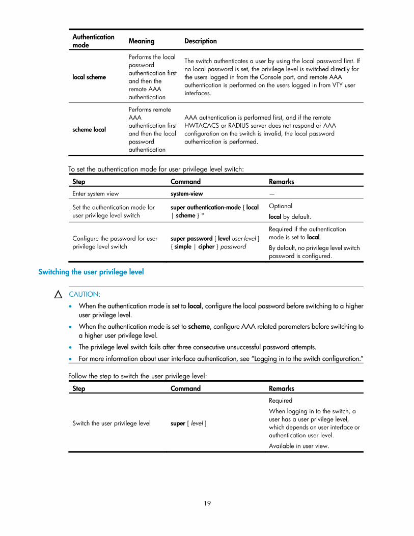
Authentication mode Meaning Description
local Local password authentication
The switch authenticates a user by using the privilege level switch password entered by the user.
When this mode is applied, you must set the password for privilege level switch with super password.
scheme
Remote AAA authentication through HWTACACS or RADIUS
The switch sends the username and password for privilege level switch to the HWTACACS or RADIUS server for remote authentication.
When this mode is applied, you must perform the following configurations: • Configure HWTACACS or RADIUS scheme and reference the
created scheme in the ISP domain. For more information, see Security Configuration Guide.
• Create the corresponding user and configure password on the HWTACACS or RADIUS server.
19
Authentication mode Meaning Description
local scheme
Performs the local password authentication first and then the remote AAA authentication
The switch authenticates a user by using the local password first. If no local password is set, the privilege level is switched directly for the users logged in from the Console port, and remote AAA authentication is performed on the users logged in from VTY user interfaces.
scheme local
Performs remote AAA authentication first and then the local password authentication
AAA authentication is performed first, and if the remote HWTACACS or RADIUS server does not respond or AAA configuration on the switch is invalid, the local password authentication is performed.
To set the authentication mode for user privilege level switch:
Step Command Remarks
Enter system view system-view —
Set the authentication mode for user privilege level switch
super authentication-mode { local | scheme } *
Optional
local by default.
Configure the password for user privilege level switch
Required if the authentication mode is set to local.
By default, no privilege level switch password is configured.
Switching the user privilege level
CAUTION:
• When the authentication mode is set to local, configure the local password before switching to a higher user privilege level.
• When the authentication mode is set to scheme, configure AAA related parameters before switching to a higher user privilege level.
• The privilege level switch fails after three consecutive unsuccessful password attempts.
• For more information about user interface authentication, see “Logging in to the switch configuration.”
Follow the step to switch the user privilege level:
Step Command Remarks
Switch the user privilege level super [ level ]
Required
When logging in to the switch, a user has a user privilege level, which depends on user interface or authentication user level.
Available in user view.
20
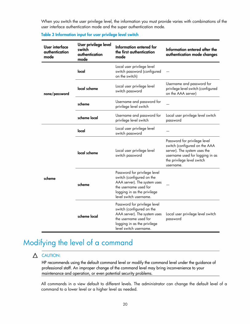
When you switch the user privilege level, the information you must provide varies with combinations of the user interface authentication mode and the super authentication mode.
Table 3 Information input for user privilege level switch
User interface authentication mode
User privilege level switch authentication mode
Information entered for the first authentication mode
Information entered after the authentication mode changes
none/password
local Local user privilege level switch password (configured on the switch)
—
local scheme Local user privilege level switch password
Username and password for privilege level switch (configured on the AAA server)
scheme Username and password for privilege level switch —
scheme local Username and password for privilege level switch
Local user privilege level switch password
scheme
local Local user privilege level switch password
—
local scheme Local user privilege level switch password
Password for privilege level switch (configured on the AAA server). The system uses the username used for logging in as the privilege level switch username.
scheme
Password for privilege level switch (configured on the AAA server). The system uses the username used for logging in as the privilege level switch username.
—
scheme local
Password for privilege level switch (configured on the AAA server). The system uses the username used for logging in as the privilege level switch username.
Local user privilege level switch password
Modifying the level of a command
CAUTION:
HP recommends using the default command level or modify the command level under the guidance of professional staff. An improper change of the command level may bring inconvenience to your maintenance and operation, or even potential security problems.
All commands in a view default to different levels. The administrator can change the default level of a command to a lower level or a higher level as needed.
21
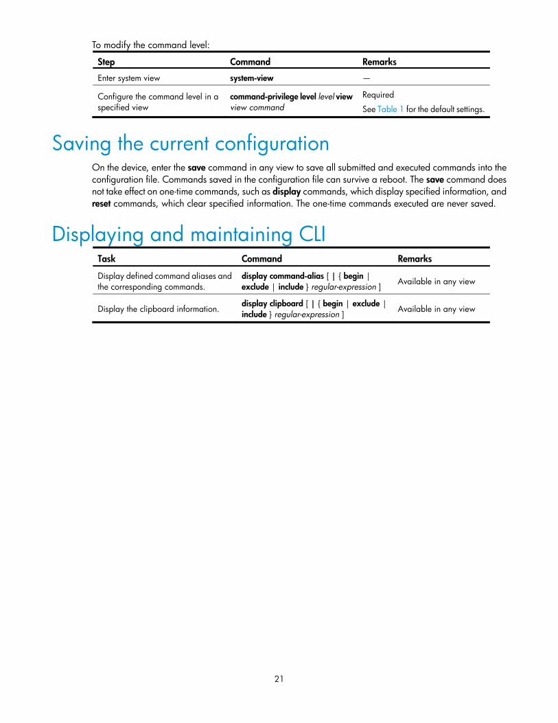
To modify the command level:
Step Command Remarks
Enter system view system-view —
Configure the command level in a specified view
command-privilege level level view view command
Required
See Table 1 for the default settings.
Saving the current configuration On the device, enter the save command in any view to save all submitted and executed commands into the configuration file. Commands saved in the configuration file can survive a reboot. The save command does not take effect on one-time commands, such as display commands, which display specified information, and reset commands, which clear specified information. The one-time commands executed are never saved.
Displaying and maintaining CLI Task Command Remarks
Display defined command aliases and the corresponding commands.
display command-alias [ | { begin | exclude | include } regular-expression ] Available in any view
Display the clipboard information. display clipboard [ | { begin | exclude | include } regular-expression ] Available in any view
22
Login methods
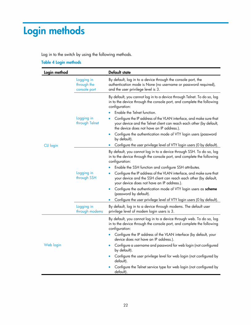
Log in to the switch by using the following methods.
Table 4 Login methods
Login method Default state
CLI login
Logging in through the console port
By default, log in to a device through the console port, the authentication mode is None (no username or password required), and the user privilege level is 3.
Logging in through Telnet
By default, you cannot log in to a device through Telnet. To do so, log in to the device through the console port, and complete the following configuration: • Enable the Telnet function. • Configure the IP address of the VLAN interface, and make sure that
your device and the Telnet client can reach each other (by default, the device does not have an IP address.).
• Configure the authentication mode of VTY login users (password by default).
• Configure the user privilege level of VTY login users (0 by default).
Logging in through SSH
By default, you cannot log in to a device through SSH. To do so, log in to the device through the console port, and complete the following configuration: • Enable the SSH function and configure SSH attributes. • Configure the IP address of the VLAN interface, and make sure that
your device and the SSH client can reach each other (by default, your device does not have an IP address.).
• Configure the authentication mode of VTY login users as scheme (password by default).
• Configure the user privilege level of VTY login users (0 by default).
Logging in through modems
By default, log in to a device through modems. The default user privilege level of modem login users is 3.
Web login
By default, you cannot log in to a device through web. To do so, log in to the device through the console port, and complete the following configuration: • Configure the IP address of the VLAN interface (by default, your
device does not have an IP address.). • Configure a username and password for web login (not configured
by default). • Configure the user privilege level for web login (not configured by
default). • Configure the Telnet service type for web login (not configured by
default).
23
Login method Default state
NMS login
By default, you cannot log in to a device through a network management station (NMS). To do so, log in to the device through the console port, and complete the following configuration: • Configure the IP address of the VLAN interface, and make sure the
device and the NMS can reach each other (by default, your device does not have an IP address.).
• Configure SNMP basic parameters.
Users and user interfaces User interface, also called “line," allows you to manage and monitor sessions between the terminal and device when you log in to the device through the console port directly, or through Telnet or SSH.
One user interface corresponds to one user interface view where you can configure a set of parameters, such as whether to authenticate users at login, whether to redirect the requests to another device, and the user privilege level after login. When the user logs in through a user interface, the parameters set for the user interface apply.
The system supports the following CLI configuration methods:
• Local configuration via the console port
• Local/Remote configuration through Telnet or SSH
The methods correspond to the following user interfaces.
• AUX user interface: Used to manage and monitor users that log in via the Console port. The type of the Console port is EIA/TIA-232 DCE.
• VTY (virtual type terminal) user interface: Used to manage and monitor users that log in via VTY. A VTY port used for Telnet or SSH access.
Only one user can use a user interface at a time. The configuration made in a user interface view applies to any login user. For example, if user A uses the console port to log in, the configuration in the AUX user interface view applies to user A; if user A logs in through VTY 1, the configuration in VTY 1 user interface view applies to user A.
A device can be equipped with one AUX user interface and 16 VTY user interfaces. These user interfaces do not associate with specific users. When a user initiates a connection request, the system automatically assigns an idle user interface with the smallest number to the user based on the login method. During the login, the configuration in the user interface view takes effect. The user interface varies depending on the login method and the login time.
24
Numbering user interfaces User interfaces can be numbered by using absolute numbering or relative numbering.
Absolute numbering
Absolute numbering identifies a user interface or a group of different types of user interfaces. The specified user interfaces are numbered from number 0 with a step of 1 and in the sequence of AUX, and VTY user interfaces. Use display user-interface command without any parameters to view supported user interfaces and their absolute numbers.
Relative numbering
Relative numbering allows you to specify a user interface or a group of user interfaces of a specific type. The number format is “user interface type + number." The following rules of relative numbering apply:
• AUX user interfaces are numbered from 0 in the ascending order, with a step of 1.
• VTY user interfaces are numbered from 0 in the ascending order, with a step of 1.
25
CLI login
The CLI enables you to interact with a device by typing text commands. At the CLI, instruct your device to perform a given task by typing a text command and then pressing Enter to submit it to your device. Compared with the graphical user interface (GUI), where you can use a mouse to perform configuration, the CLI allows you to enter more information in one command line.
Log in to the device at the CLI through the console port, Telnet, SSH, or modem.
• By default, log in to a device through the console port without any authentication, which introduces security problems.
• By default, you cannot log in to a device through Telnet, SSH, so you cannot remotely manage and maintain the device.
Therefore, you must perform configurations to increase device security and manageability.
Logging in through the console port Logging in through the console port is the most common login method, and is also the first step to configure other login methods.
By default, log in to a device through its console port only. After logging in to the device through the console port, configure other login methods.
Configuration requirements
Object Requirements
Device No configuration requirement
Terminal Run the hyper terminal program.
Configure the hyper terminal attributes.
The port properties of the hyper terminal must be the same as the default settings of the console port shown in the following table.
Setting Default
Bits per second 9,600 bps
Flow control None
Parity None
Stop bits 1
Data bits 8
26
Login procedure
WARNING!
Identify interfaces to avoid connection errors.
1. As shown in Figure 2, use the console cable shipped with the device to connect the PC and the device. Plug the DB-9 connector of the console cable into the serial port of the PC, and plug the RJ-45 connector into the console port of your device.
Figure 2 Connect the device and PC through a console cable
The serial port of a PC does not support hot-swap. Do not plug or unplug the console cable into or from the PC when your device is powered on.
• To connect the PC to the device, first plug the DB-9 connector of the console cable into the PC, and then plug the RJ-45 connector of the console cable into your device.
• To disconnect the PC from the device, first unplug the RJ-45 connector and then the DB-9 connector.
2. Launch a terminal emulation program (such as HyperTerminal in Windows XP/Windows 2000). The following takes the HyperTerminal of Windows XP as an example. Select a serial port to be connected to the device, and set terminal parameters as follows: set Bits per second to 9600, Data bits to 8, Parity to None, Stop bits to 1, and Flow control to None, as shown in Figure 3 through Figure 5.
NOTE:
On Windows 2003 Server operating system, you must add the HyperTerminal program first, and then log in to and manage the device as described in this document. On Windows 2008 Server, Windows 7, Windows Vista, or some other operating system, you must obtain a third party terminal control programfirst, and follow the user guide or online help of that program to log in to the device.
Figure 3 Connection description
27
Figure 4 Specify the serial port used to establish the connection
Figure 5 Set the properties of the serial port
28
3. Turn on the device. You are prompted to press Enter if the device successfully completes the power-on self-test (POST). A prompt such as <HP> appears after you press Enter, as shown in Figure 6.
Figure 6 Configuration page
4. Execute commands to configure the device or check the running status of the device. To get help, enter ?.
Console login authentication modes The following authentication modes are available for console port login: none, password, and scheme.
• none—Requires no username and password at the next login through the console port. This mode is insecure.
• password—Requires password authentication at the next login through the console port. Keep your password.
• scheme—Requires username and password authentication at the next login through the console port. Authentication falls into local authentication and remote authentication. To use local authentication, configure a local user and related parameters. To use remote authentication, configure the username and password on the remote authentication server. For more information about authentication modes and parameters, see Security Configuration Guide. Keep your username and password.
29
The following table lists console port login configurations for different authentication modes:
Authentication mode Configuration Remarks
None Configure not to authenticate users. For more information, see “Configuring none authentication for console login.”
Password
Configure the device to authenticate users by using the local password.
For more information, see “Configuring password authentication for console login.” Set the local password.
Scheme
Configure the authentication scheme.
For more information, see “Configuring scheme authentication for console login.”
Select an authentication scheme.
Remote AAA authentication
Configure RADIUS/ HWTACACS scheme.
Configure AAA scheme used by the domain.
Configure username and password on the AAA server.
Local authentication
Configure authentication username and password.
Configure AAA scheme used by the domain as local.
NOTE:
A newly configured authentication mode does not take effect unless you exit and enter the CLI again.
Configuring none authentication for console login Prerequisites
You have logged in to the device.
By default, log in to the device through the console port without authentication and have user privilege level 3 after login. For information about logging in to the device with the default configuration, see “Configuration requirements.”
30
Procedure
To configure none authentication for console login:
Step Command Remarks
1. Enter system view. system-view —
2. Enter AUX user interface view. user-interface aux first-number [ last-number ]
—
3. Specify the none authentication mode.
authentication-mode none
Required.
By default, log in to the device through the console port without authentication, and have user privilege level 3 after login.
4. Configure common settings for AUX user interface view.
— Optional.
See “Configuring common settings for console login (optional).”
After the configuration, the next time you log in to the device through the console port, you are prompted to press enter. A prompt such as <HP> appears after you press Enter, as shown in Figure 7.
Figure 7 Configuration page
Configuring password authentication for console login Prerequisites
You have logged in to the device.
31
By default, log in to the device through the console port without authentication and have user privilege level 3 after login. For information about logging in to the device with the default configuration, see “Configuration requirements.”
Procedure
To configure password authentication for console login:
Step Command Remarks
1. Enter system view. system-view —
2. Enter AUX user interface view. user-interface aux first-number [ last-number ]
—
3. Configure the authentication mode as local password authentication.
authentication-mode password
Required.
By default, log in to the device through the console port without authentication and have user privilege level 3 after login.
4. Set the local password. set authentication password { cipher | simple } password
Required.
By default, no local password is set.
5. Configure common settings for AUX user interface view. —
Optional.
See “Configuring common settings for console login (optional).”
When you log in to the device through the console port after the configuration, you are prompted to enter a login password. A prompt such as <HP> appears after you enter the password and press Enter, as shown in Figure 8.
Figure 8 Configuration page
32
Configuring scheme authentication for console login Prerequisites
You have logged in to the device.
By default, log in to the device through the console port without authentication and have user privilege level 3 after login. For information about logging in to the device with the default configuration, see “Configuration requirements.”
Procedure
To configure scheme authentication for console login:
Step Command Remarks
1. Enter system view. system-view —
2. Enter AUX user interface view.
user-interface aux first-number [ last-number ]
—
3. Specify scheme authentication mode.
authentication- mode scheme
Required.
Whether local, RADIUS, or HWTACACS authentication is adopted depends on the configured AAA scheme.
By default, users that log in through the console port are not authenticated.
4. Enable command authorization.
command authorization
Optional. • By default, command authorization is not enabled. • By default, the command level depends on the user
privilege level. A user is authorized a command level not higher than the user privilege level. With command authorization enabled, the command level for a login user is determined by both the user privilege level and AAA authorization. If a user executes a command of the corresponding command level, the authorization server checks whether the command is authorized. If it is, the command can be executed.
• Before enabling command authorization, configure the AAA authorization server. After you enable command authorization, only commands authorized by the AAA authorization server can be executed.
33
Step Command Remarks
5. Enable command accounting.
command accounting
Optional. • By default, command accounting is disabled. The
accounting server does not record the commands executed by users.
• Command accounting allows the HWTACACS server to record all commands executed by users, regardless of command execution results. This helps control and monitor user operations on the device. If command accounting is enabled and command authorization is not enabled, every executed command is recorded on the HWTACACS server. If both command accounting and command authorization are enabled, only the authorized and executed commands are recorded on the HWTACACS server.
• Configure the AAA accounting server before enabling command accounting.
6. Return to system view. quit —
7. Configure the authentication mode.
Enter ISP domain view
domain domain-name Optional.
By default, the AAA scheme is local.
If you specify the local AAA scheme, you must perform local user configuration. If you specify an existing scheme by providing the radius-scheme-name argument, perform the following configuration as well: • For RADIUS and HWTACACS configuration, see
Security Configuration Guide. • Configure the username and password on the AAA
server. (For more information about AAA, see Security Configuration Guide.)
Apply specified AAA scheme to the domain
authentication default { hwtacacs- scheme hwtacacs- scheme-name [ local ] | local | none | radius- scheme radius- scheme- name [ local ] }
Exit to system view
quit
8. Create a local user and enter local user view.
local-user user-name
Required.
By default, no local user exists.
9. Set the authentication password for the local user.
password { cipher | simple } password
Required.
10. Specifies the command level of the local user.
authorization- attribute level level
Optional.
By default, the command level is 0.
11. Specify the service type for the local user.
service-type terminal
Required.
By default, no service type is specified.
12. Configure common settings for AUX user interface view.
— Optional.
See “Configuring common settings for console login (optional).”
34
After you enable command authorization, you must perform the following configuration to make the function take effect:
• Create a HWTACACS scheme, and specify the IP address of the authorization server and other authorization parameters. For more information about AAA, see Security Configuration Guide.
• Reference the created HWTACACS scheme in the ISP domain. For more information about AAA, see Security Configuration Guide.
After you enable command accounting, you must perform the following configuration to make the function take effect:
• Create a HWTACACS scheme, and specify the IP address of the accounting server and other accounting parameters. For more information about AAA, see Security Configuration Guide.
• Reference the created HWTACACS scheme in the ISP domain. For more information about AAA, see Security Configuration Guide.
When users adopt the scheme mode to log in to the device, the level of the commands that the users can access depends on the user privilege level defined in the AAA scheme.
• When the AAA scheme is local, the user privilege level is defined by the authorization-attribute level level.
• When the AAA scheme is RADIUS or HWTACACS, the user privilege level is configured on the RADIUS or HWTACACS server.
• For more information about AAA, RADIUS, and HWTACACS, see Security Configuration Guide.
When you log in to the device through the console port after the configuration, you are prompted to enter a login username and password. A prompt such as <HP> appears after you enter the password and username and press Enter, as shown in Figure 9.
Figure 9 Configuration page
35
Configuring common settings for console login (optional)
CAUTION:
The common settings configured for console login take effect immediately. If you configure the common settings after you log in through the console port, the current connection may be interrupted, so you shoulduse another login method. After you configure common settings for console login, you must modify the settings on the terminal to make them consistent with those on the device.
Step Command Remarks
1. Enter system view. system-view —
2. Enable display of copyright information. copyright-info enable
Optional.
Enabled by default.
3. Enter AUX user interface view. user-interface aux first-number [ last-number ]
—
4. Configure AUX user interface view properties.
Configure baud rate. speed speed-value
Optional.
By default, the transmission rate is 9600 bps.
Transmission rate is the number of bits that the device transmits to the terminal per second.
Configure parity check mode.
parity { even | mark | none | odd | space }
Optional.
none by default.
Configure stop bits. stopbits { 1 | 1.5 | 2 }
Optional.
By default, the stop bit of the console port is 1.
Stop bits are the last bits transmitted in data transmission to unequivocally indicate the end of a character. The more the bits are, the slower the transmission is.
Configure data bits.
databits { 5 | 6 | 7 | 8 }
Optional.
By default, the data bit of the console port is 8.
Data bits is the number of bits representing one character. The setting depends on the contexts to be transmitted. For example, set it to 7 if standard ASCII characters are to be sent, and set it to 8 if extended ASCII characters are to be sent.
Define shortcut key for enabling a terminal session.
activation-key character
Optional.
By default, press Enter to enable a terminal session.
Define shortcut key for terminating tasks.
escape-key { default | character }
Optional.
By default, press Ctrl+C to terminate a task.
36
Step Command Remarks
Configure flow control mode.
flow-control { hardware | none | software }
Optional.
By default, the value is none
Configure type of terminal display
terminal type { ansi | vt100 }
Optional
By default, the terminal display type is ANSI.
The device supports two types of terminal display: ANSI and VT100. HP recommends setting the display type of both the device and the client to VT100. If the device and the client use different display types (for example, hyper terminal or Telnet terminal) or both are set to ANSI, when the total number of characters of the edited command line exceeds 80, an anomaly such as cursor corruption or abnormal display of the terminal display may occur on the client.
Configure user privilege level for login users
user privilege level level
Optional
By default, the default command level is 3 for the AUX user interface.
Set the maximum number of lines on the next screen.
screen-length screen-length
Optional
By default, the next screen displays 24 lines.
A value of 0 disables the function.
Set the size of history command buffer
history-command max-size value
Optional
By default, the buffer saves 10 history commands at most.
Set the idle-timeout timer
idle-timeout minutes [ seconds ]
Optional
The default idle-timeout is 10 minutes. The system automatically terminates the user’s connection if no information interaction occurs between the device and the user within the idle-timeout time.
Setting idle-timeout to 0 disables the timer.
Logging in through Telnet The device supports Telnet. Telnet to the device to remotely manage and maintain it, as shown in Figure 10.
Figure 10 Telnet login
37
The following table shows the configuration requirements of Telnet login.
Object Requirements
Telnet server
Configure the IP address of the VLAN interface, and make sure the Telnet server and client can reach each other.
Configure the authentication mode and other settings.
Telnet client Run the Telnet client program.
Obtain the IP address of the VLAN interface on the server.
By default, the device is enabled with the Telnet server and client functions.
• On a device that serves as the Telnet client, log in to a Telnet server to perform operations on the server.
• On a device that serves as the Telnet server, configure the authentication mode and user privilege level for Telnet users. By default, you cannot log in to the device through Telnet. Before Telnet to the device, you must log in to the device through the console port, enable Telnet server, and configure the authentication mode, user privilege level, and common settings.
Telnet login authentication modes Three authentication modes are available for Telnet login: none, password, and scheme.
• none—Requires no username and password at the next login through Telnet. This mode is insecure.
• password—Requires password authentication at the next login through Telnet. Keep your password. If you lose your password, log in to the device through the console port to view or modify the password.
• scheme—Requires username and password authentication at the next login through Telnet. Authentication falls into local authentication and remote authentication. To use local authentication, configure a local user and related parameters. To use remote authentication, configure the username and password on the remote authentication server. For more information about authentication modes and parameters, see Security Configuration Guide. Keep your username and password. If you lose your local authentication password, log in to the device through the console port to view or modify the password. If you lose your remote authentication password, contact the administrator.
The following table lists Telnet login configurations for different authentication modes.
Authentication mode Configuration Remarks
None Configure not to authenticate users. For more information, see “Configuring none authentication for Telnet login.”
Password
Configure the device to authenticate users by using the local password.
For more information, see “Configuring password authentication for Telnet login.” Set the local password.
38
Authentication mode Configuration Remarks
Scheme
Configure the authentication scheme.
For more information, see “Configuring scheme authentication for Telnet login.”
Select authentication scheme.
Remote AAA authentication
Configure RADIUS/HWTACACS scheme.
Configure AAA scheme used by the domain.
Configure username and password on the AAA server.
Local authentication
Configure authentication username and password.
Configure AAA scheme used by the domain as local.
Configuring none authentication for Telnet login Prerequisites
You have logged in to the device.
By default, log in to the device through the console port without authentication and have user privilege level 3 after login. For information about logging in to the device with the default configuration, see “Configuration requirements.”
Procedure
To configure none authentication for Telnet login:
Step Command Remarks
1. Enter system view. system-view —
2. Enable Telnet. telnet server enable Required.
By default, the Telnet service is disenabled.
3. Enter one or multiple VTY user interface views.
user-interface vty first-number [ last-number ]
—
4. Specify the none authentication mode. authentication-mode none
Required.
By default, authentication mode for VTY user interfaces is password.
39
Step Command Remarks
5. Configure the command level for login users on the current user interfaces.
user privilege level level Required.
By default, the default command level is 0 for VTY user interfaces.
6. Configure common settings for VTY user interfaces.
— Optional.
See “Configuring common settings for VTY user interfaces (optional).”
When you log in to the device through Telnet again:
• You enter the VTY user interface, as shown in Figure 11.
• If “All user interfaces are used, please try later!” is displayed, it means the current login users exceed the maximum number. Please try later.
Figure 11 Configuration page
40
Configuring password authentication for Telnet login Prerequisites
You have logged in to the device.
By default, log in to the device through the console port without authentication and have user privilege level 3 after login. For information about logging in to the device with the default configuration, see “Configuration requirements.”
Procedure
To configure password authentication for Telnet login:
Step Command Remarks
1. Enter system view. system-view —
2. Enable Telnet. telnet server enable Required.
By default, the Telnet service is disenabled.
3. Enter one or multiple VTY user interface views.
user-interface vty first-number [ last-number ] —
4. Specify the password authentication mode. authentication-mode password
Required.
By default, authentication mode for VTY user interfaces is password.
5. Set the local password. set authentication password { cipher | simple } password
Required.
By default, no local password is set.
6. Configure the user privilege level for login users. user privilege level level
Required.
0 by default.
7. Configure common settings for VTY user interfaces.
— Optional.
See “Configuring common settings for VTY user interfaces (optional).”
When you log in to the device through Telnet again:
• You are required to enter the login password. A prompt such as <HP> appears after you enter the correct password and press Enter, as shown in Figure 12.
• If “All user interfaces are used, please try later!” is displayed, it means the number of current concurrent login users exceed the maximum. Please try later.
41
Figure 12 Configuration page
Configuring scheme authentication for Telnet login Prerequisites
You have logged in to the device.
By default, log in to the device through the console port without authentication and have user privilege level 3 after login. For information about logging in to the device with the default configuration, see “Configuration requirements.”
Procedure
Step Command Remarks
1. Enter system view. system-view —
2. Enable Telnet. telnet server enable Required.
By default, the Telnet service is disabled.
3. Enter one or multiple VTY user interface views.
user-interface vty first-number [ last-number ]
—
4. Specify scheme authentication mode.
authentication-mode scheme
Required.
Whether local, RADIUS, or HWTACACS authentication is adopted depends on the configured AAA scheme.
By default, local authentication is adopted.
42
Step Command Remarks
5. Enable command authorization.
command authorization
Optional. • By default, command authorization is not enabled. • By default, the command level depends on the user
privilege level. A user is authorized a command level not higher than the user privilege level. With command authorization enabled, the command level for a login user is determined by both the user privilege level and AAA authorization. If a user executes a command of the corresponding command level, the authorization server checks whether the command is authorized. If it is, the command can be executed.
• Before enabling command authorization, configure the AAA authorization server. After you enable command authorization, only commands authorized by the AAA authorization server can be executed.
6. Enable command accounting.
command accounting
Optional. • By default, command accounting is disabled. The
accounting server does not record the commands executed by users.
• Command accounting allows the HWTACACS server to record all executed commands that are supported by the device, regardless of the command execution result. This helps control and monitor user operations on the device. If command accounting is enabled and command authorization is not enabled, every executed command is recorded on the HWTACACS server. If both command accounting and command authorization are enabled, only the authorized and executed commands are recorded on the HWTACACS server.
• Configure the AAA accounting server before enabling command accounting.
7. Exit to system view. quit —
8. Configure authentication mode.
Enter default ISP domain view.
domain domain-name Optional.
By default, the AAA scheme is local.
If you specify the local AAA scheme, perform the configuration concerning local user as well. If you specify an existing scheme by providing the radius-scheme-name argument, perform the following configuration as well: • For RADIUS and HWTACACS configuration, see
Security Configuration Guide. • Configure the username and password on the AAA
server. (For more information, see Security Configuration Guide.)
Specify AAA scheme to be applied to the domain.
authentication default { hwtacacs- scheme hwtacacs- scheme-name [ local ] | local | none | radius- scheme radius- scheme-name [ local ] }
Exit to system view.
quit
43
Step Command Remarks 9. Create local user and
enter local user view. local-user user-name By default, no local user exists.
10. Set local password. password { cipher | simple } password
Required.
By default, no local password is set.
11. Specify command level of the local user.
authorization-attribute level level
Optional.
By default, the command level is 0.
12. Specify service type for the local user.
service-type telnet Required.
By default, no service type is specified.
13. Exit to system view. quit —
14. Configure common settings for VTY user interfaces.
— Optional.
See “Configuring common settings for VTY user interfaces (optional).”
After you enable command authorization, you must perform the following configuration to make the function take effect:
• Create a HWTACACS scheme, and specify the IP address of the authorization server and other authorization parameters. For more information, see Security Configuration Guide.
• Reference the created HWTACACS scheme in the ISP domain. For more information, see Security Configuration Guide.
After you enable command accounting, you must perform the following configuration to make the function take effect:
• Create a HWTACACS scheme, and specify the IP address of the accounting server and other accounting parameters. For more information, see Security Configuration Guide.
• Reference the created HWTACACS scheme in the ISP domain. For more information, see Security Configuration Guide.
When users adopt the scheme mode to log in to the device, the level of the commands that the users can access depends on the user privilege level defined in the AAA scheme.
• When the AAA scheme is local, the user privilege level is defined by the authorization-attribute level level.
• When the AAA scheme is RADIUS or HWTACACS, the user privilege level is configured on the RADIUS or HWTACACS server.
For more information about AAA, RADIUS, and HWTACACS, see Security Configuration Guide.
When you log in to the device through Telnet again:
• You are required to enter the login username and password. A prompt such as <HP> appears after you enter the correct username (for example, admin) and password and press Enter, as shown in Figure 13.
• After entering the correct username and password, if the device prompts you to enter another password of the specified type, you will be authenticated for the second time. In other words, to pass authentication, you must enter a correct password as prompted.
• If “All user interfaces are used, please try later!” is displayed, it means the current login users exceed the maximum number. Please try later.
44
Figure 13 Configuration page
Configuring common settings for VTY user interfaces (optional)
CAUTION:
The auto-execute command command may disable you from configuring the system through the user interface to which the command is applied. Use it with caution.
Before executing the auto-execute command command and saving the configuration (by using save). Be sure you can access the device through VTY and AUX user interfaces so you can remove the configuration when a problem occurs.
Step Command Remarks
1. Enter system view. system-view —
2. Enable display of copyright information.
copyright-info enable
Optional.
Enabled by default.
3. Create a VLAN interface and enter VLAN interface view.
interface vlan- interface vlan- interface-id
Required.
If the VLAN interface already exists, the command enters the VLAN interface view.
4. Specify an IP address for a VLAN interface.
ip address ip- address { mask | mask-length }
Required.
By default, no IP address is specified for a VLAN interface.
5. Return to system view. quit —
6. Enter one or multiple VTY user interface views.
user-interface vty first-number [ last-number ]
—
45
Step Command Remarks
7. User interface configuration
Enable the terminal service. shell
Optional.
Enabled by default.
Enable the current user interfaces to support either Telnet, SSH, or both of them.
protocol inbound { all | ssh | telnet }
Optional.
By default, both protocols are supported.
The configuration takes effect next time you log in.
Define a shortcut key for terminating tasks.
escape-key { default | character }
Optional.
By default, press Ctrl+C to terminate a task.
Configure the type of terminal display.
terminal type { ansi | vt100 }
Optional.
By default, the terminal display type is ANSI.
Set the maximum number of lines on the next screen.
screen-length screen-length
Optional.
By default, the next screen displays 24 lines.
A value of 0 disables the function.
Set the size of history command buffer.
history-command max-size value
Optional.
By default, the buffer saves 10 history commands.
Set the idle-timeout timer.
idle-timeout minutes [ seconds ]
Optional.
The default idle-timeout is 10 minutes for all user interfaces.
The system automatically terminates the user’s connection if no information interaction occurs between the device and the user in timeout time.
Setting idle-timeout to 0 disables the timer.
Specify a command to be automatically executed when a user logs in to the current user interface
auto-execute command command
Optional
By default, command auto-execution is disabled.
The system automatically executes the specified command when a user logs in to the user interface, and tears down the user connection after the command is executed. If the command triggers another task, the system does not tear down the user connection until the task is completed. A Telnet command is usually specified to enable the user to automatically Telnet to the specified device.
46
Configuring the device to log in to a Telnet server as a Telnet client Prerequisites
You have logged in to the device.
By default, log in to the device through the console port without authentication and have user privilege level 3 after login. For information about logging in to the device with the default configuration, see “Configuration requirements.”
Figure 14 Log in to another device from the current device
NOTE:
If the Telnet client port and the Telnet server port that connect them are not in the same subnet, make surethat the two devices can reach each other.
Procedure
Follow the step below to configure the device to log in to a Telnet server as a Telnet client:
Step Command Remarks
1. Configure the device to log in to a Telnet server as a Telnet client.
By, no source IPv4 address or source interface is specified. The source IPv4 address is selected by routing.
47
Logging in through SSH SSH offers an approach to log into a remote device securely. By providing encryption and strong authentication, it protects devices against attacks such as IP spoofing and plain-text password interception. The device supports SSH, and you can log in to the device through SSH to remotely manage and maintain the device, as shown in Figure 15.
Figure 15 SSH login diagram
The following table shows the configuration requirements of SSH login.
Object Requirements
SSH server
Configure the IP address of the VLAN interface, and make sure the SSH server and client can reach each other.
Configure the authentication mode and other settings.
SSH client Run the SSH client program.
Obtain the IP address of the VLAN interface on the server.
By default, the device is enabled with the SSH server and client functions.
• On a device that serves as the SSH client, log in to an SSH server to perform operations on the server.
• On a device that serves as the SSH server, configure the authentication mode and user level for SSH users. By default, password authentication is adopted for SSH login, but no login password is configured, so you cannot log in to the device through SSH by default. Before log in to the device through SSH, you must log in to the device through the console port and configure the authentication mode, user level, and common settings.
Configuring the SSH server
NOTE:
This chapter describes how to configure an SSH client by using password authentication. For more information about SSH and how to configure an SSH client by using publickey, see Security Configuration Guide.
Prerequisites
You have logged in to the device, and want to log in to the device through SSH in the future.
By default, log in to the device through the console port without authentication and have user privilege level 3 after login. For information about logging in to the device with the default configuration, see “Configuration requirements.”
48
Procedure
To configure the device that serves as an SSH server:
Step Command Remarks
1. Enter system view. system-view —
2. Create local key pairs. public-key local create { dsa | rsa }
Required.
By default, no local key pairs are created.
3. Enable SSH server. ssh server enable Required.
By default, SSH server is disabled.
4. Enter one or more VTY user interface views.
user-interface vty first-number [ last-number ]
—
5. Specify the scheme authentication mode.
authentication-mode scheme
Required.
By default, authentication mode for VTY user interfaces is password.
6. Enable the current user interface to support SSH.
protocol inbound { all | ssh }
Optional.
By default, Telnet and SSH protocols are both supported.
7. Enable command authorization.
command authorization
Optional. • By default, command authorization is not
enabled. • By default, command level for a login user
depends on the user privilege level. The user is authorized the command with the default level not higher than the user privilege level. With the command authorization configured, the command level for a login user is determined by both the user privilege level and AAA authorization. If a user executes a command of the corresponding command level, the authorization server checks whether the command is authorized. If it is, the command can be executed.
49
Step Command Remarks
8. Enable command accounting. command accounting
Optional • By default, command accounting is
disabled. The accounting server does not record the commands executed by users.
• Command accounting allows the HWTACACS server to record all executed commands that are supported by the device, regardless of the command execution result. This helps control and monitor user operations on the device. If command accounting is enabled and command authorization is not enabled, every executed command is recorded on the HWTACACS server. If both command accounting and command authorization are enabled, only the authorized and executed commands are recorded on the HWTACACS server.
9. Exit to system view quit —
10. Configure the authentication mode.
Enter the default ISP domain view.
domain domain-name
Optional.
By default, the AAA scheme is local.
If you specify the local AAA scheme, perform the configuration concerning local user as well. If you specify an existing scheme by providing the radius-scheme-name argument, perform the following configuration as well: • For RADIUS and HWTACACS
configuration, see Security Configuration Guide.
• Configure the username and password on the AAA server. (For more information, see Security Configuration Guide.)
Apply the specified AAA scheme to the domain.
authentication default { hwtacacs-scheme hwtacacs-scheme-name [ local ] | local | none | radius-scheme radius-scheme-name [ local ] }
Exit to system view.
quit
11. Create a local user and enter local user view. local-user user-name
Required.
By default, no local user exists.
12. Set the local password. password { cipher | simple } password
Required.
By default, no local password is set.
13. Specify the command level of the local user.
authorization-attribute level level
Optional.
By default, the command level is 0.
14. Specify the service type for the local user. service-type ssh
Required.
By default, no service type is specified.
15. Return to system view. quit —
50
Step Command Remarks
16. Create an SSH user, and specify the authentication mode for the SSH user.
ssh user username service-type stelnet authentication-type { password | { any | password-publickey | publickey } assign publickey keyname }
Required.
By default, no SSH user exists, and no authentication mode is specified.
17. Configure common settings for VTY user interfaces. —
Optional.
See “Configuring common settings for VTY user interfaces (optional).”
After you enable command authorization or command accounting, you must perform the following configuration to make the function take effect:
• Create a HWTACACS scheme, and specify the IP address of the authorization server and other authorization parameters.
• Reference the created HWTACACS scheme in the ISP domain.
For more information, see Security Configuration Guide.
When users adopt the scheme mode to log in to the device, the level of the commands that the users can access depends on the user privilege level defined in the AAA scheme.
• When the AAA scheme is local, the user privilege level is defined by the authorization-attribute level level.
• When the AAA scheme is RADIUS or HWTACACS, the user privilege level is configured on the RADIUS or HWTACACS server.
• For more information about AAA, RADIUS, and HWTACACS, see Security Configuration Guide.
Configuring the SSH client to log in to the SSH server Prerequisites
You have logged in to the device.
By default, log in to the device through the console port without authentication and have user privilege level 3 after login. For information about logging in to the device with the default configuration, see “Configuration requirements.”
Figure 16 Log in to another device from the current device
NOTE:
If the SSH client and the SSH server are not in the same subnet, make sure that the two devices can reacheach other.
51
Procedure
Configure other settings for the SSH client to work with the SSH server. For more information, see Security Configuration Guide. To configure the SSH client to log in to the SSH server:
Step Command Remarks
Log in to an IPv4 SSH server. ssh2 server
Required
server is the IPv4 address or host name of the server.
Available in user view
Log in to an IPv6 SSH server. ssh2 ipv6 server
Required
server is the IPv6 address or host name of the server.
Available in user view
Logging in through modems The administrator can use two modems to remotely maintain a switch through its Console port over the Public Switched Telephone Network (PSTN) when the IP network connection is broken.
Configuration requirements By default, no authentication is needed when you log in through modems, and the default user privilege level is 3.
To use this method, perform necessary configurations at both the device side and administrator side.
The following table shows the configuration requirements of remote login through the console port by using modem dial-in:
Object Requirement
Administrator side
The PC is correctly connected to the modem.
The modem is connected to a telephone cable that works normally.
The telephone number of the remote modem connected to the Console port of the remote switch is obtained.
Device side
The Console port is correctly connected to the modem.
Configurations have been configured on the modem.
The modem is connected to a telephone cable that works properly.
Authentication configuration has been completed on the remote switch.
52
Login procedure 1. Set up a configuration environment as shown in Figure 2: connect the serial port of the PC and the
Console port of the device to a modem respectively.
Figure 2 Set up a configuration terminal
2. Configuration on the administrator side
The PC and the modem are correctly connected, the modem is connected to a telephone cable, and the telephone number of the remote modem connected to the Console port of the remote switch is obtained.
NOTE:
On the device:
• The baud rate of the Console port is lower than the transmission rate of the modem. Otherwise, packetsmay be lost.
• The parity check mode, stop bits, and data bits of the Console port adopt the default settings.
3. Perform the following configurations on the modem that is directly connected to the device: AT&F ----------------------- Restore the factory defaults
ATS0=1 ----------------------- Configure auto-answer on first ring
AT&D ----------------------- Ignore data Terminal Ready signals
AT&K0 ----------------------- Disable local flow control
AT&R1 ----------------------- Ignore Data Flow Control signals
AT&S0 ----------------------- Force DSR to remain on
ATEQ1&W ----------------------- Disable the modem from response to commands and save the configuration
To verify your configuration, enter AT&V to show the configuration results.
NOTE:
The configuration commands and the output for different modems may be different. For more information,see the user guide of your modem.
4. Launch a terminal emulation utility (such as HyperTerminal in Windows XP/Windows 2000), create a new connection (the telephone number is the number of the modem connected to the device).
NOTE:
On Windows 2003 Server operating system, you must add the HyperTerminal program first, and then login to and manage the device as described in this document. On Windows 2008 Server, Windows 7, Windows Vista, or some other operating system, you must obtain a third party terminal control programfirst, and follow the user guide or online help of that program to log in to the device.
5. Dial the destination number on the PC to establish a connection with the device, as shown in Figure 3 through Figure 5.
53
Figure 3 Connection Description
Figure 4 Enter the phone number
Figure 5 Dial the number
54
6. Character string CONNECT9600 is displayed on the terminal. Then a prompt appears when you press Enter.
Figure 6 Configuration page
7. If the authentication mode is password, a prompt (for example, HP) appears when you enter the configured password on the remote terminal. Then configure or manage the router. To get help, enter ?.
8. Execute commands to configure the device or check the running status of the device. To get help, enter ?.
NOTE:
• To terminate the connection between the PC and device, run ATH command on the terminal to terminate the connection between the PC and modem. If you cannot execute the command on the terminal, enterAT+ + + and then press Enter. When you are prompted OK, run ATH, and the connection is terminated
if OK is displayed. Alternately, terminate the connection between the PC and device by clicking on the hyper terminal window.
• Do not close the hyper terminal directly. Otherwise, the remote modem remains online, and you will failto dial in at the next time.
Modem login authentication modes The following authentication modes are available for modem dial-in login: none, password, and scheme.
• none—Requires no username and password at the next login through modems. This mode is insecure.
• password—Requires password authentication at the next login through the console port. Keep your password.
• scheme—Requires username and password authentication at the next login through the console port. Authentication falls into local authentication and remote authentication. To use local authentication, configure a local user and related parameters. To use remote authentication, configure the username and
55
password on the remote authentication server. For more information about authentication modes and parameters, see Security Configuration Guide. Keep your username and password.
The following table lists modem login configurations for different authentication modes:
Authentication mode Configuration Remarks
None Configure not to authenticate users.
For more information, see “Configuring none authentication for modem login.”
Password
Configure the device to authenticate users by using the local password.
For more information, see “Configuring password authentication for modem login.” Set the local password.
Scheme
Configure the authentication scheme.
For more information, see “Configuring scheme authentication for modem login.”
Select an authentication scheme.
Remote AAA authentication
Configure a RADIUS/HWTACACS scheme.
Configure the AAA scheme used by the domain.
Configure the username and password on the AAA server.
Local authentication
Configure the authentication username and password.
Configure the AAA scheme used by the domain as local.
NOTE:
Modem login authentication changes do not take effect until you exit the CLI and log in again.
Configuring none authentication for modem login Prerequisites
You have logged in to the device.
By default, log in to the device through the console port without authentication and have user privilege level 3 after login. For information about logging in to the device with the default configuration, see “Configuration requirements.”
56
Procedure
Step Command Remarks
1. Enter system view. system-view —
2. Enter one or more AUX user interface views.
user-interface aux first-number [ last-number ]
—
3. Specify the none authentication mode. authentication-mode none
Required.
By default, users that log in through the console port are not authenticated.
4. Configuring common settings for modem login.
— Optional.
See “Configuring common settings for modem login (optional).”
When you log in to the device through modems after the configuration, you are prompted to press Enter. A prompt such as <HP> appears after you press Enter, as shown in Figure 7.
Figure 7 Configuration page
Configuring password authentication for modem login Prerequisites
You have logged in to the device.
By default, log in to the device through the console port without authentication and have user privilege level 3 after login. For information about logging in to the device with the default configuration, see “Configuration requirements.”
57
Procedure
To configure password authentication for modem login:
Step Command Remarks
Enter system view system-view —
Enter one or more AUX user interface views
user-interface aux first-number [ last-number ]
—
Specify the password authentication mode
authentication-mode password Required
By default, the authentication mode is none for modem users
Set the local password set authentication password { cipher | simple } password
Required
By default, no local password is set.
Configuring common settings for modem login —
Optional
For more information, see “Configuring common settings for modem login (optional).”
When you log in to the device through modems after the configuration, you are prompted to enter a login password. A prompt such as <HP> appears after you enter the password and press Enter, as shown in Figure 8.
Figure 8 Configuration page
58
Configuring scheme authentication for modem login Prerequisites
You have logged in to the device.
By default, log in to the device through the console port without authentication and have user privilege level 3 after login. For information about logging in to the device with the default configuration, see “Configuration requirements.”
Procedure
To configure scheme authentication for modem login:
Step Command Remarks
1. Enter system view. system-view —
2. Enter AUX user interface view. user-interface aux first-number [ last-number ]
—
3. Specify the scheme authentication mode.
authentication- mode scheme
Required.
Whether local, RADIUS, or HWTACACS authentication is adopted depends on the configured AAA scheme.
By default, the authentication mode is none for modem users.
Optional. • By default, command authorization is not
enabled. • By default, command level for a login user
depends on the user privilege level. The user is authorized the command with the default level not higher than the user privilege level. With the command authorization configured, the command level for a login user is determined by both the user privilege level and AAA authorization. If a user executes a command of the corresponding command level, the authorization server checks whether the command is authorized. If it is, the command can be executed.
• Before enabling command authorization, configure the AAA authorization server. After you enable command authorization, only commands authorized by the AAA authorization server can be executed.
59
Step Command Remarks
5. Enable command accounting. command accounting
Optional. • By default, command accounting is
disabled. The accounting server does not record the commands executed by users.
• Command accounting allows the HWTACACS server to record all executed commands that are supported by the device, regardless of the command execution result. This helps control and monitor user operations on the device. If command accounting is enabled and command authorization is not enabled, every executed command is recorded on the HWTACACS server. If both command accounting and command authorization are enabled, only the authorized and executed commands are recorded on the HWTACACS server.
• Configure the AAA accounting server before enabling command accounting.
6. Exit to system view quit —
7. Configure the authentication mode.
Enter the default ISP domain view.
domain domain-name
Optional.
By default, the AAA scheme is local.
If you specify the local AAA scheme, perform the configuration concerning local user as well. If you specify an existing scheme by providing the radius-scheme-name argument, perform the following configuration as well: • For RADIUS and HWTACACS
configuration, see Security Configuration Guide.
• Configure the username and password on the AAA server. (For more information, see Security Configuration Guide.)
Apply the specified AAA scheme to the domain.
authentication default { hwtacacs- scheme hwtacacs- scheme-name [ local ] | local | none | radius- scheme radius- scheme-name [ local ] }
Return to system view.
quit
8. Create a local user and enter local user view.
local-user user-name
Required.
By default, no local user exists.
9. Set the authentication password for the local user.
password { cipher | simple } password
Required.
10. Specifies the command level of the local user.
authorization-attribute level level
Optional.
By default, the command level is 0.
11. Specify the service type for the local user.
service-type terminal
Required.
By default, no service type is specified.
12. Configuring common settings for modem login.
— Optional.
See “Configuring common settings for modem login (optional).”
60
After you enable command authorization, you must perform the following configuration to make the function take effect:
• Create a HWTACACS scheme, and specify the IP address of the authorization server and other authorization parameters. For more information, see Security Configuration Guide.
• Reference the created HWTACACS scheme in the ISP domain. For more information, see Security Configuration Guide.
After you enable command accounting, you must perform the following configuration to make the function take effect:
• Create a HWTACACS scheme, and specify the IP address of the accounting server and other accounting parameters. For more information, see Security Configuration Guide.
• Reference the created HWTACACS scheme in the ISP domain. For more information, see Security Configuration Guide.
When users adopt the scheme mode to log in to the device, the level of the commands that the users can access depends on the user privilege level defined in the AAA scheme.
• When the AAA scheme is local, the user privilege level is defined by the authorization-attribute level level.
• When the AAA scheme is RADIUS or HWTACACS, the user privilege level is configured on the RADIUS or HWTACACS server.
For more information about AAA, RADIUS, and HWTACACS, see Security Configuration Guide.
When you log in to the device through modems after the configuration, you are prompted to enter a login username and password. A prompt such as <HP> appears after you enter the password and username and press Enter, as shown in Figure 9.
Figure 9 Configuration page
61
Configuring common settings for modem login (optional)
CAUTION:
• The common settings configured for Console login take effect immediately. If you configure the commonsettings after you log in through the Console port, the current connection may be interrupted. To avoid this problem, use another login method. After you configure the common settings for Console login, you must modify the settings on the terminal to make them consistent with those on the device.
• The baud rate of the Console port must be lower than the transmission rate of the modem. Otherwise, packets may be lost.
Step Command Remarks
1. Enter system view. system-view —
2. Enable display of copyright information. copyright-info enable
Optional
Enabled by default.
3. Enter one or more AUX user interface views.
user-interface aux first-number [ last-number ]
—
4. Configure AUX user interface properties.
Configure baud rate speed speed-value
Optional
By default, the baud rate is 9600 bps.
Transmission rate is the number of bits that the device transmits to the terminal per second.
Configure parity check mode
parity { even | mark | none | odd | space }
Optional
By default, the parity check mode is none, which means no check bit.
Configure stop bits stopbits { 1 | 1.5 | 2 }
Optional
By default, the stop bit of the console port is 1.
Stop bits are the last bits transmitted in data transmission to unequivocally indicate the end of a character. The more the bits are, the slower the transmission is.
Configure data bits
databits { 5 | 6 | 7 | 8 }
Optional
By default, the data bit is 8.
Data bits is the number of bits representing one character. The setting depends on the contexts to be transmitted. For example, set it to 7 if standard ASCII characters are to be sent, and set it to 8 if extended ASCII characters are to be sent.
Define shortcut key for starting a session
activation-key character
Optional
By default, press Enter to start a session.
62
Step Command Remarks
Define shortcut key for terminating tasks
escape-key { default | character }
Optional
By default, press Ctrl+C to terminate a task.
Configure flow control mode
flow-control { hardware | none | software }
Optional
By default, the value is none
Configure type of terminal display
terminal type { ansi | vt100 }
Optional
By default, the terminal display type is ANSI.
The device supports two types of terminal display: ANSI and VT100. HP recommends setting the display type of both the device and the client to VT100. If the device and the client use different display types (for example, hyper terminal or Telnet terminal) or both are set to ANSI, when the total number of characters of the edited command line exceeds 80, an anomaly such as cursor corruption or abnormal display of the terminal display may occur on the client.
Configure user privilege level for login users
user privilege level level
Optional
3 by default.
Set maximum number of lines on the next screen
screen-length screen-length
Optional
By default, the next screen displays 24 lines at most.
A value of 0 disables the function.
Set size of the history command buffer
history-command max-size value
Optional
By default, the buffer saves 10 history commands at most.
Set idle- timeout timer
idle-timeout minutes [ seconds ]
Optional
The default idle-timeout is 10 minutes. The system automatically terminates the user’s connection if no information interaction occurs between the device and the user within the idle-timeout time.
Setting idle-timeout to 0 disables the timer.
63
Displaying and maintaining CLI login
Task Command Remarks
Display the source IP address/ interface specified for Telnet packets.
display telnet client configuration [ | { begin | exclude | include } regular- expression ]
Available in any view.
Display information about the user interfaces that are being used.
display users [ | { begin | exclude | include } regular- expression ]
Available in any view.
Displays information about all user interfaces that the device supports.
display users all [ | { begin | exclude | include } regular -expression ]
Available in any view.
Display user interface information.
display user-interface [ num1 | { aux | vty } num2 ] [ summary ] [ | { begin | exclude | include } regular- expression ]
Available in any view.
Release a specified user interface. free user-interface { num1 | { aux | vty } num2 }
Available in user view.
Multiple users can log in to the system to simultaneously configure the device. In some circumstances, when the administrator wants to make configurations without interruption from the users that have logged in through other user interfaces, the administrator can execute the command to release the connections established on the specified user interfaces.
You cannot use this command to release the connection you are using.
Lock the current user interface. lock Available in user view.
By default, the current user interface is not locked.
Send messages to the specified user interfaces.
send { all | num1 | { aux | vty } num2 } Available in user view.
64
Web login
Overview The device provides a built-in web server. It enables you to log in to the web interface of the device from a PC. Web login is disabled by default.
To enable web login, log in to the device via the console port, and perform the following configuration:
• Enable HTTP or HTTPS service.
• Configure the IP address of the VLAN interface.
• Configure a username and password.
The device supports the following web login methods:
• HTTP login—Used for transferring web page information across the Internet. It is an application-layer protocol in the TCP/IP protocol suite. The connection-oriented Transport Control Protocol (TCP) is adopted at the transport layer. The device supports HTTP 1.0.
• HTTPS login—Supports the SSL protocol and uses it to encrypt the data exchanged between the HTTPS client and the server to ensure data security and integrity. Define a certificate attribute-based access control policy to allow legal clients to access the device securely and prohibit illegal clients.
The following table shows the configuration requirements of web login.
Object Requirements
Device
Configure the IP address of the VLAN interface.
Make sure the device and the PC can reach each other.
Configuring HTTP login Required to use one approach.
Configuring HTTPS login
PC Install a web browser.
Obtain the IP address of the VLAN interface of the device.
65
Configuring HTTP login
Step Command Remarks
1. Enter system view. system-view —
2. Enable the HTTP service. ip http enable Required.
Enabled by default.
3. Configure the HTTP service port number. ip http port port-number
Optional.
80 by default.
If you execute the command multiple times, the last one takes effect.
4. Associate the HTTP service with an ACL. ip http acl acl-number
Optional.
By default, the HTTP service is not associated with any ACL.
Associating the HTTP service with an ACL enables the device to allow only clients permitted by the ACL to access the device.
5. Create a local user and enter local user view.
local-user user-name Required.
By default, no local user is configured.
6. Configure a password for the local user.
password { cipher | simple } password
Required.
By default, no password is configured for the local user.
7. Specify the command level of the local user.
authorization-attribute level level
Required.
No command level is configured for the local user.
8. Specify the Telnet service type for the local user.
service-type telnet Required.
By default, no service type is configured for the local user.
9. Exit to system view. quit —
10. Create a VLAN interface and enter its view.
interface vlan-interface vlan-interface-id
Required.
If the VLAN interface already exists, the command enters its view.
11. Assign an IP address and subnet mask to the VLAN interface.
ip address ip-address { mask | mask-length }
Required.
By default, no IP address is assigned to the VLAN interface.
66
Configuring HTTPS login
Step Command Remarks
1. Enter system view. system-view —
2. Configure PKI and SSL related features. —
Required
By default, PKI and SSL are not configured. • For more information about PKI, see Security
Configuration Guide. • For more information about SSL, see Security
Configuration Guide.
3. Associate the HTTPS service with an SSL server policy.
ip https ssl-server-policy policy-name
Required
By default, the HTTPS service is not associated with any SSL server policy. • If you disable the HTTPS service, the system
automatically de-associates the HTTPS service from the SSL service policy. Before re-enabling the HTTPS service, associate the HTTPS service with an SSL server policy first.
• Any changes to the SSL server policy associated with the HTTP service that is enabled do not take effect.
4. Enable the HTTPS service.
ip https enable
Required
Disabled by default.
Enabling the HTTPS service triggers an SSL handshake negotiation process. During the process: • If the local certificate of the device exists, the SSL
negotiation succeeds, and the HTTPS service can be started normally.
• If no local certificate exists, a certificate application process is triggered by the SSL negotiation.
Because the application process takes much time, the SSL negotiation often fails and the HTTPS service cannot be started normally. In that case, you must run ip https enable multiple times to start the HTTPS service.
67
Step Command Remarks
5. Associate the HTTPS service with a certificate attribute-based access control policy.
ip https certificate access-control-policy policy-name
Optional.
By default, the HTTPS service is not associated with any certificate-based attribute access control policy. • Associating the HTTPS service with a
certificate-based attribute access control policy enables the device to control the access rights of clients.
• You must configure client-verify enable in the associated SSL server policy. If not, no clients can log in to the device.
• The associated SSL server policy must contain at least one permit rule. Otherwise, no clients can log in to the device.
• For more information about certificate attribute-based access control policies, see Security Configuration Guide.
6. Configure the port number of the HTTPS service.
ip https port port-number
Optional.
443 by default.
7. Associate the HTTPS service with an ACL.
ip https acl acl-number
Required.
By default, the HTTPS service is not associated with any ACL.
Associating the HTTPS service with an ACL enables the device to allow only clients permitted by the ACL to access the device.
8. Create a local user and enter local user view.
local-user user-name Required.
By default, no local user is configured.
9. Configure a password for the local user.
password { cipher | simple } password
Required.
By default, no password is configured for the local user.
10. Specify the command level of the local user.
authorization-attribute level level
Required.
By default, no command level is configured for the local user.
11. Specify the Telnet service type for the local user.
service-type telnet Required.
By default, no service type is configured for the local user.
12. Exit to system view. quit —
13. Create a VLAN interface and enter its view.
interface vlan-interface vlan-interface-id
Required.
If the VLAN interface already exists, the command enters its view.
14. Assign an IP address and subnet mask to the VLAN interface.
ip address ip-address { mask | mask-length }
Required.
By default, no IP address is assigned to the VLAN interface.
68
Displaying and maintaining web login
Task Command Remarks
Display information about web users.
display web users [ | { begin | exclude | include } regular-expression ] Available in any view.
Display HTTP state information. display ip http [ | { begin | exclude | include } regular-expression ] Available in any view.
Display HTTPS state information. display ip https [ | { begin | exclude | include } regular-expression ] Available in any view.
Web login example
HTTP login example Network requirements
As shown in Figure 10, the PC is connected to the device over an IP network. The IP address of the Device is 192.168.20.66/24.
Figure 10 Network diagram for configuring HTTP login
Procedure
1. Configuration on the device
# Log in to the device via the console port and configure the IP address of VLAN 1 of the device. VLAN 1 is the default VLAN. <Sysname> system-view
[Sysname] interface vlan-interface 1
[Sysname-VLAN-interface1] ip address 192.168.20.66 255.255.255.0
[Sysname-VLAN-interface1] quit
# Create a local user named admin, and set the password to admin for the user. Specify the Telnet service type for the local user, and set the command level to 3 for this user. [Sysname] local-user admin
# On the PC, run the web browser. Enter the IP address of the device in the address bar, 192.168.20.66 in this example. The web login page appears, as shown in Figure 4.
Figure 4 Web login page
# Enter the user name, password, verify code, select English, and click Login. The homepage appears. After login, configure device settings through the web interface.
HTTPS login example Network requirements
As shown in Figure 5, to prevent unauthorized users from accessing the Device, configure HTTPS login as follows:
• Configure the Device as the HTTPS server, and request a certificate for it.
• The Host acts as the HTTPS client. Request a certificate for it.
In this example, Windows Server acts as the CA. Install Simple Certificate Enrollment Protocol (SCEP) add-on on the CA. The name of the CA that issues certificates to the Device and Host is new-ca.
Before performing the following configuration, make sure that the Device, Host, and CA can reach each other.
70
Figure 5 Network diagram for configuring HTTPS login
Procedure
1. Configure the device that acts as the HTTPS server
# Configure a PKI entity, configure the common name of the entity as http-server1, and the FQDN of the entity as ssl.security.com. <Device> system-view
[Device] pki entity en
[Device-pki-entity-en] common-name http-server1
[Device-pki-entity-en] fqdn ssl.security.com
[Device-pki-entity-en] quit
# Create a PKI domain, specify the trusted CA as new-ca, the URL of the server for certificate request as http://10.1.2.2/certsrv/mscep/mscep.dll, authority for certificate request as RA, and the entity for certificate request as en. [Device] pki domain 1
[Device-pki-domain-1] certificate request entity en
[Device-pki-domain-1] quit
# Create RSA local key pairs. [Device] public-key loc al create rsa
# Retrieve the CA certificate from the certificate issuing server. [Device] pki retrieval-certificate ca domain 1
# Request a local certificate from a CA through SCEP for the device. [Device] pki request-certificate domain 1
# Create an SSL server policy myssl, specify PKI domain 1 for the SSL server policy, and enable certificate-based SSL client authentication. [Device] ssl server-policy myssl
# Create a certificate attribute group mygroup1, and configure a certificate attribute rule, specifying that the Distinguished Name (DN) in the subject name includes the string of new-ca. [Device] pki certificate attribute-group mygroup1
# Create a certificate attribute-based access control policy myacp. Configure a certificate attribute-based access control rule, specifying that a certificate is considered valid when it matches an attribute rule in certificate attribute group myacp. [Device] pki certificate access-control-policy myacp
# Associate the HTTPS service with SSL server policy myssl. [Device] ip https ssl-server-policy myssl
# Associate the HTTPS service with certificate attribute-based access control policy myacp. [Device] ip https certificate access-control-policy myacp
# Enable the HTTPS service. [Device] ip https enable
# Create a local user named usera, set the password to 123 for the user, and specify the Telnet service type for the local user. [Device] local-user usera
[Device-luser-usera] password simple 123
[Device-luser-usera] service-type telnet
2. Configure the host that acts as the HTTPS client
On the host, run the IE browser. In the address bar, enter http://10.1.2.2/certsrv and request a certificate for the host as prompted.
3. Verify the configuration
Enter https://10.1.1.1 in the address bar, and select the certificate issued by new-ca. Then the web login page of the Device appears. On the login page, type the username usera, and password 123 to enter the web management page.
To log in to the web interface through HTTPS, enter the URL address starting with https://. To log in to the web interface through HTTP, enter the URL address starting with http://.
• For more information about PKI configuration commands, see Security Command Reference.
• For more information about the public-key local create rsa command, see Security Command Reference.
• For more information about SSL configuration commands, see Security Command Reference.
72
NMS login
Overview A Network Management Station (NMS) runs the SNMP client software. It offers a user-friendly interface to facilitate network management. An agent is a program that resides in the device. It receives and handles requests from the NMS. An NMS is a manager in an SNMP enabled network, whereas agents are managed by the NMS. The NMS and agents exchange information through the SNMP protocol. The device supports multiple NMS programs, such as iMC and CAMS.
By default, you cannot log in to the device through NMS. To enable NMS login, log in to the device via the console port and make the configurations described in the following table.
The following table shows the configuration requirements of NMS login.
Object Requirements
Device
Configure the IP address of the VLAN interface.
Make sure the device and the NMS can reach each other.
Configure SNMP settings.
NMS Configure the NMS. For more information, see the manual of your NMS.
Configuring NMS login Connect the Ethernet port of the PC to an Ethernet port of VLAN 1 of the device, as shown in Figure 6. Make sure the PC and VLAN 1 interface can reach each other.
The device supports three SNMP versions: SNMPv1, SNMPv2c and SNMPv3. For more information about SNMP, see Network Management and Monitoring Configuration Guide.
Figure 6 Network diagram for configuring NMS login
73
Configuring SNMPv1 and SNMPv2c settings
Step Command Remarks
1. Enter system view. system-view —
2. Enable SNMP agent. snmp-agent
Optional.
Disabled by default.
Enable SNMP agent with this command or any command that begins with snmp-agent.
The direction configuration approach is for SNMPv1 or SNMPv2c. The community name configured on the NMS should be consistent with the username configured on the agent.
The indirect configuration approach is for SNMPv3.
If the cipher keyword is specified, both auth-password and priv-password are cipher-text passwords.
NMS login example In this example, iMC is used as the NMS.
1. Configuration on the device
# Assign IP address of device. Make sure the device and the NMS can reach each other. (Configuration steps are omitted.)
# Enter system view. <Sysname> system-view
# Enable the SNMP agent. [Sysname] snmp-agent
# Configure an SNMP group. [Sysname] snmp-agent group v3 managev3group read-view test write-view test
# Add a user to the SNMP group. [Sysname] snmp-agent usm-user v3 managev3user managev3group
75
2. Configuration on the NMS
On the PC, start the browser. In the address bar, enter http://192.168.20.107:8080/imc, where 192.168.20.107 is the IP address of the iMC.
Figure 7 iMC login page
76
Enter the username and password, and then click Login. The iMC homepage appears, as shown in Figure 8.
Figure 8 iMC homepage
Log in to the iMC and configure SNMP settings for the iMC to find the device. After the device is found, manage and maintain the device through the iMC. For example, query device information or configure device parameters.
The SNMP settings on the iMC must be the same as those configured on the device. If not, the device cannot be found or managed by the iMC. See the iMC manuals for more information.
Click Help in the upper right corner of each configuration page to get corresponding help information.
77
User login control
Overview The device provides the following login control methods.
Login Through Login control methods ACL used
Telnet
Configuring source IP-based login control over Telnet users Basic ACL
Configuring source and destination IP-based login control over Telnet users Advanced ACL
Configuring source MAC-based login control over Telnet users Ethernet frame header ACL
NMS Configuring source IP-based login control over NMS users Basic ACL
Web Configuring source IP-based login control over web users Basic ACL
Configuring login control over Telnet users
Configuration preparation Before configuration, determine the permitted or denied source IP addresses, source MAC addresses, and destination IP addresses.
Configuring source IP-based login control over Telnet users Because basic ACLs match the source IP addresses of packets, use basic ACLs to implement source IP-based login control over Telnet users. Basic ACLs are numbered from 2000 to 2999. For more information about ACL, see ACL and QoS Configuration Guide.
To configure source IP-based login control over Telnet users:
Step Command Remarks
1. Enter system view. system-view —
2. Create a basic ACL and enter its view, or enter the view of an existing basic ACL.
acl [ ipv6 ] number acl-number [ match-order { config | auto } ]
5. Enter user interface view. user-interface [ type ] first-number [ last-number ] —
6. Use the ACL to control user login by source IP address.
acl [ ipv6 ] acl-number { inbound | outbound }
Required. • inbound—Filters incoming
Telnet packets. • outbound—Filters
outgoing Telnet packets.
Configuring source and destination IP-based login control over Telnet users
Because advanced ACLs can match both source and destination IP addresses of packets, use advanced ACLs to implement source and destination IP-based login control over Telnet users. Advanced ACLs are numbered from 3000 to 3999. For more information about ACL, see ACL and QoS Configuration Guide.
To configure source and destination IP-based login control over Telnet users:
Step Command Remarks
1. Enter system view. system-view —
2. Create an advanced ACL and enter its view, or enter the view of an existing advanced ACL.
acl [ ipv6 ] number acl-number [ match-order { config | auto } ]
Required.
By default, no advanced ACL exists.
3. Configure rules for the ACL. rule [ rule-id ] { permit | deny } rule-string Required.
4. Exit advanced ACL view. quit —
5. Enter user interface. user-interface [ type ] first-number [ last-number ] —
6. Use the ACL to control user login by source and destination IP addresses.
acl [ ipv6 ] acl-number { inbound | outbound }
Required. • inbound—Filters incoming
Telnet packets. • outbound—Filters outgoing
Telnet packets.
Configuring source MAC-based login control over Telnet users Ethernet frame header ACLs can match the source MAC addresses of packets, so use Ethernet frame header ACLs to implement source MAC-based login control over Telnet users. Ethernet frame header ACLs are numbered from 4000 to 4999. For more information about ACL, see ACL and QoS Configuration Guide.
79
To configure source MAC-based login control over Telnet users:
Step Command Remarks
1. Enter system view. system-view —
2. Create an Ethernet frame header ACL and enter its view.
acl number acl-number [ match-order { config | auto } ]
Required.
By default, no advanced ACL exists.
3. Configure rules for the ACL. rule [ rule-id ] { permit | deny } rule-string
Required.
4. Exit the advanced ACL view. quit —
5. Enter user interface view. user-interface [ type ] first-number [ last-number ] —
6. Use the ACL to control user login by source MAC address. acl acl-number inbound
Required.
inbound: Filters incoming Telnet packets.
NOTE:
The above configuration does not take effect if the Telnet client and server are not in the same subnet.
Source MAC-based login control configuration example Network requirements
As shown in Figure 9, configure an ACL on the Device to permit only incoming Telnet packets sourced from Host A and Host B.
Figure 9 Network diagram for configuring source MAC-based login control
80
Procedure
# Configure basic ACL 2000, and configure rule 1 to permit packets sourced from Host B, and rule 2 to permit packets sourced from Host A. <Sysname> system-view
# Reference ACL 2000 in user interface view to allow Telnet users from Host A and Host B to access the Device. [Sysname] user-interface vty 0 15
[Sysname-ui-vty0-15] acl 2000 inbound
Configuring source IP-based login control over NMS users
Log in to the NMS to remotely manage the devices. SNMP is used for communication between the NMS and the agent that resides in the device. By using the ACL, control SNMP user access to the device.
Configuration preparation Before configuration, determine the permitted or denied source IP addresses.
Configuring source IP-based login control over NMS users Because basic ACLs match the source IP addresses of packets, use basic ACLs to implement source IP-based login control over NMS users. Basic ACLs are numbered from 2000 to 2999. For more information about ACL, see ACL and QoS Configuration Guide.
To configure source IP-based login control over NMS users:
Step Command Remarks
1. Enter system view. system-view —
2. Create a basic ACL and enter its view, or enter the view of an existing basic ACL.
acl [ ipv6 ] number acl-number [ match-order { config | auto } ]
Configuring source IP-based login control over web users
Log in to the web management page of the device through HTTP/HTTPS to remotely manage the devices. By using the ACL, control web user access to the device.
Configuration preparation Before configuration, determine the permitted or denied source IP addresses.
Configuring source IP-based login control over web users Because basic ACLs match the source IP addresses of packets, use basic ACLs to implement source IP-based login control over web users. Basic ACLs are numbered from 2000 to 2999. For more information about ACL, see ACL and QoS Configuration Guide.
To configure source IP-based login control over web users:
Step Command Remarks
1. Enter system view. system-view —
2. Create a basic ACL and enter its view, or enter the view of an existing basic ACL.
acl [ ipv6 ] number acl-number [ match-order { config | auto } ]
5. Associate the HTTP service with the ACL. ip http acl acl-number Required to use one command. 6. Associate the HTTPS service with the ACL. ip https acl acl-number
83
Logging off online web users
Step Command Remarks
1. Log off online web users. free web-users { all | user-id user-id | user-name user-name }
Required.
Execute the command in user interface view.
Source IP-based login control over web users configuration example
Network requirements
As shown in Figure 11, configure the device to allow only web users from Host B to access.
Figure 11 Network diagram for configuring source IP-based login control
Procedure
# Create ACL 2000, and configure rule 1 to permit packets sourced from Host B. <Sysname> system-view
# Associate the ACL with the HTTP service so that only web users from Host B are allowed to access the device. [Sysname] ip http acl 2030
84
Configuring FTP
Overview FTP is an application layer protocol for sharing files between server and client over a TCP/IP network.
FTP uses TCP ports 20 and 21 for file transfer. Port 20 is used to transmit data, and port 21 to transmit control commands. For more information about FTP basic operations, see RFC 959.
FTP transfers files in the following modes:
• ASCII mode—Transfers files as text, like .txt, .bat, and .cfg files.
• Binary mode—Transfers files as raw data, like .app, .bin, and .btm files.
Operation
CAUTION:
• Make sure that the FTP server and the FTP client can reach each other before establishing the FTP connection.
• When you use IE to log in to the device serving as the FTP server, some FTP functions are not available. This is because multiple connections are established during the login process but the device supports only one connection at a time.
FTP adopts the client/server model. Your device can function either as the client or the server (as shown in Figure 12).
• When the device serves as the FTP client, use Telnet or an emulation program to log in to the device from the PC, run ftp to establish a connection from the device (FTP client) to the PC (FTP server), and then upload/download files to/from the server.
• When the device serves as the FTP server, run the FTP client program on the PC to establish a connection to the FTP server and upload/download files to/from the server.
Figure 12 Network diagram for FTP
When the device serves as the FTP client, you must perform the following configuration:
Table 5 Configuration when the device serves as the FTP client
Device Configuration Remarks
Device (FTP client) Use ftp to establish the connection to the remote FTP server.
If the remote FTP server supports anonymous FTP, the device can log in to it directly; if not, the device must obtain the FTP username and password first to log in to the remote FTP server.
85
Device Configuration Remarks
PC (FTP server) Enable FTP server on the PC, and configure the username, password, user privilege level, and so on.
—
When the device serves as the FTP server, you must perform the following configuration:
Table 6 Configuration when the device serves as the FTP server
Device Configuration Remarks
Device (FTP server)
Enable the FTP server function. Disabled by default.
Use display ftp-server to view the FTP server configuration on the device.
Configure authentication and authorization.
Configure the username, password, and authorized directory for an FTP user.
The device does not support anonymous FTP for security reasons. You must set a valid username and password. By default, authenticated users can access the root directory of the device.
Configure the FTP server operating parameters.
Parameters such as the FTP connection timeout time.
PC (FTP client) Use the FTP client program to log in to the FTP server.
Log in to the FTP server only after you enter the correct FTP username and password.
Configuring the FTP client Only users with the manage level can use ftp to log in to an FTP server, enter FTP client view, and execute directory and file related commands. However, whether the commands can be executed successfully depends on the authorizations of the FTP server.
Establishing an FTP connection Before access the FTP server, you must first establish a connection from the FTP client to the FTP server. Either use ftp to establish the connection directly or use open command in FTP client view to establish the connection.
When using ftp, specify the source interface (such as a loopback) or source IP address. The primary IP address of the specified source interface or the specified source IP address is used as the source IP address of sent FTP packets. The source address of the transmitted packets is selected following these rules:
• If no source address is specified, the FTP client uses the IP address of the interface determined by the matched route as the source IP address to communicate with an FTP server.
• If the source address is specified with the ftp client source or ftp, this source address is used to communicate with an FTP server.
• If you use ftp client source and ftp to specify a source address respectively, the source address specified with ftp is used to communicate with an FTP server.
• The source address specified with ftp client source is valid for all FTP connections and the source address specified with ftp is valid only for the current FTP connection.
86
To establish an IPv4 FTP connection:
Step Command Remarks
1. Enter system view. system-view —
2. Configure the source address of the FTP client.
The ftp command is available in user view, and open is available in FTP client view.
5. Log in to the remote FTP server indirectly in FTP client view.
ftp
open server-address [ service-port ]
If no primary IP address is configured on the specified source interface, you cannot establish an FTP connection.
If you use ftp client source to configure a source interface and then use it to configure a source IP address, the source IP address overwrites the source interface, and vice versa.
To establish an IPv6 FTP connection:
Step Command Remarks
1. Log in to the remote FTP server directly in user view.
Operating FTP server directories After the switch serving as the FTP client has established a connection with an FTP server, create or delete folders under the authorized directory of the FTP server. For more information about establishing an FTP connection, see “Establishing an FTP connection.”
To operate the directories on an FTP server:
Task Command Remarks
Display detailed information about a directory or file on the remote FTP server. dir [ remotefile [ localfile ] ] Optional
Query a directory or file on the remote FTP server. ls [ remotefile [ localfile ] ] Optional
Change the working directory of the remote FTP server. cd { directory | .. | / } Optional
Exit the current working directory and return to an upper level directory of the remote FTP server.
cdup Optional
Display the working directory that is being accessed. pwd Optional
Create a directory on the remote FTP server. mkdir directory Optional
Remove the specified working directory on the remote FTP server. rmdir directory Optional
Operating FTP server files After the switch serving as the FTP client has established a connection with an FTP server, upload a file to or download a file from the FTP server under the authorized directory of the FTP server by following these steps. For information about establishing an FTP connection, see “Establishing an FTP connection.”
Use dir or ls to view the directory and the location of the file on the FTP server.
Delete useless files for effective use of the storage space.
Set the file transfer mode. FTP transmits files in two modes:
• ASCII mode—Transfers files as text.
• Binary mode—Transfers files as raw data.
Use lcd to view the local working directory of the FTP client. Upload the file under this directory, or save the downloaded file under this directory.
Upload or download the file.
88
To operate the files on an FTP server:
Task Command Remarks
Display detailed information about a directory or file on the remote FTP server.
dir [ remotefile [ localfile ] ]
Optional.
The ls command only displays the name of a directory or file. The dir command displays detailed information such as the file size and creation time.
Query a directory or file on the remote FTP server. ls [ remotefile [ localfile ] ]
Optional.
The ls command only displays the name of a directory or file. The dir command displays detailed information such as the file size and creation time.
Delete the specified file on the remote FTP server permanently.
delete remotefile Optional.
Set the file transfer mode to ASCII. ascii Optional.
ASCII by default.
Set the file transfer mode to binary. binary Optional.
ASCII by default.
Set the data transmission mode to passive. passive Optional.
Passive by default.
Display the local working directory of the FTP client. lcd Optional.
Upload a file to the FTP server. put localfile [ remotefile ] Optional.
Download a file from the FTP server. get remotefile [ localfile ] Optional.
Using another username to log in to an FTP server After the switch serving as the FTP client has established a connection with the FTP server, use another username to log in to the FTP server. For more information about establishing an FTP connection, see “Establishing an FTP connection.”
This feature allows you to switch to different user levels without affecting the current FTP connection; if you enter an incorrect username or password, the current connection is terminated, and you must log in again to access the FTP server.
Follow the step below to use another username to log in to the FTP server:
Task Command Remarks
Use another username to re-log in after successfully logging in to the FTP server. user username [ password ] Optional.
89
Maintaining and debugging an FTP connection After a switch serving as the FTP client has established a connection with the FTP server, perform the following operations to locate and diagnose problems encountered in an FTP connection. For more information about establishing an FTP connection, see “Establishing an FTP connection.”
Task Command Remarks
Display the help information of FTP-related commands supported by the remote FTP server.
remotehelp [ protocol-command ] Optional.
Enable information display in a detailed manner. verbose Optional.
Enabled by default.
Enable FTP related debugging when the switch acts as the FTP client. debugging
Optional.
Disabled by default.
Terminating an FTP connection After the switch serving as the FTP client has established a connection with the FTP server, use any of the following commands to terminate an FTP connection. For more information about establishing an FTP connection, see “Establishing an FTP connection.”
Task Command Remarks
Terminate the connection to the FTP server without exiting FTP client view. disconnect
Optional.
Equal to the close.
Terminate the connection to the FTP server without exiting FTP client view. close
Optional.
Equal to disconnect.
Terminate the connection to the FTP server and return to user view.
bye Optional.
Equal to the quit command in FTP client view.
Terminate the connection to the FTP server and return to user view. quit
Optional.
Available in FTP client view, equal to the bye.
FTP client configuration example Network requirements
• As shown in Figure 13, use Device as an FTP client and PC as the FTP server. Their IP addresses are 10.2.1.1/16 and 10.1.1.1/16 respectively. Device and PC are reachable to each other.
• Device downloads a boot file from PC for device upgrade, and uploads the configuration file to PC for backup.
• On PC, an FTP user account has been created for the FTP client, with the username being abc and the password being pwd.
90
Figure 13 Network diagram for FTPing a boot file from an FTP server
Procedure
CAUTION:
• The boot file used for the next startup must be saved under the root directory of the storage medium. Copy or move a file to the root directory of the storage medium. For more information about boot-loader, see Fundamentals Command Reference.
• If the available memory space of the device is not enough, use fixdisk to clear the memory or use delete/unreserved file-url to delete the files not in use and then perform the following operations.
# Log in to the server through FTP. <Sysname> ftp 10.1.1.1
Trying 10.1.1.1
Connected to 10.1.1.1
220 WFTPD 2.0 service (by Texas Imperial Software) ready for new user
User(10.1.1.1:(none)):abc
331 Give me your password, please
Password:
230 Logged in successfully
# Set the file transfer mode to binary to transmit boot file. [ftp] binary
200 Type set to I.
# Download the boot file newest.bin from PC to Device. [ftp] get newest.bin
# Upload the configuration file config.cfg of Device to the server for backup. [ftp] ascii
[ftp] put config.cfg back-config.cfg
227 Entering Passive Mode (10,1,1,1,4,2).
125 ASCII mode data connection already open, transfer starting for /config.cfg.
226 Transfer complete.
FTP: 3494 byte(s) sent in 5.646 second(s), 618.00 byte(s)/sec.
[ftp] bye
# Specify newest.bin as the main boot file to be used at the next startup. <Sysname> boot-loader file newest.bin main
# Reboot the device, and the boot file is updated at the system reboot. <Sysname> reboot
91
FTP client configuration example Network requirements
• As shown in Figure 14, use Device as an FTP client and PC as the FTP server. Their IP addresses are 10.2.1.1/16 and 10.1.1.1/16 respectively. Device and PC are reachable to each other.
• Device downloads a boot file from PC for device upgrade, and uploads the configuration file to PC for backup.
• On PC, an FTP user account has been created for the FTP client, with the username being abc and the password being pwd.
Figure 14 Network diagram for FTPing a boot file from an FTP server
Procedure
CAUTION:
• The boot file used for the next startup must be saved under the root directory of the storage medium. Copy or move a file to the root directory of the storage medium. For more information about boot-loader, see Fundamentals Command Reference.
• If the available memory space of the device is not enough, use fixdisk to clear the memory or use delete/unreserved file-url to delete the files not in use and then perform the following operations.
# Log in to the server through FTP. <Sysname> ftp 10.1.1.1
Trying 10.1.1.1 ...
Connected to 10.1.1.1.
220 WFTPD 2.0 service (by Texas Imperial Software) ready for new user
User(10.1.1.1:(none)):abc
331 Give me your password, please
Password:
230 Logged in successfully
# Set the file transfer mode to binary to transmit boot file. [ftp] binary
200 Type set to I.
# Download the boot file newest.bin from PC to the device.
• Download the boot file newest.bin from PC to the root directory of the storage medium on the master. [ftp] get newest.bin
92
• Download the boot file newest.bin from PC to the root directory of the storage medium of a subordinate switch (with member ID of 2).
[ftp] get newest.bin slot2#flash:/newest.bin
# Upload the configuration file config.cfg of the device to the server for backup. [ftp] ascii
[ftp] put config.cfg back-config.cfg
227 Entering Passive Mode (10,1,1,1,4,2).
125 ASCII mode data connection already open, transfer starting for /config.cfg.
226 Transfer complete.
FTP: 3494 byte(s) sent in 5.646 second(s), 618.00 byte(s)/sec.
[ftp] bye
# Specify newest.bin as the main boot file to be used at the next startup for all member devices. <Sysname> boot-loader file newest.bin slot all main
This command will set the boot file of the specified board. Continue? [Y/N]:y
The specified file will be used as the main boot file at the next reboot on slot 1!
The specified file will be used as the main boot file at the next reboot on slot 2!
# Reboot the device, and the boot file is updated at the system reboot. <Sysname> reboot
Configuring the FTP server
Configuring FTP server operating parameters The FTP server uses one of the following modes to update a file when you upload the file (use put) to the FTP server:
• Fast mode—The FTP server starts writing data to the storage medium after a file is transferred to the memory. This prevents the existing file on the FTP server from being corrupted in the event that anomaly, power failure for example, occurs during a file transfer.
• Normal mode—The FTP server writes data to the storage medium while receiving data. This means that any anomaly, power failure for example, during file transfer might result in file corruption on the FTP server. This mode, however, consumes less memory space than the fast mode.
93
To configure the FTP server:
Step Command Remarks
1. Enter system view. system-view —
2. Enable the FTP server ftp server enable Required.
Disabled by default.
3. Use an ACL to control FTP clients’ access to the switch.
ftp server acl acl-number
Optional.
By default, no ACL is used to control FTP clients’ access to the switch.
4. Configure the idle-timeout timer. ftp timeout minutes
Optional.
30 minutes by default.
Within the idle-timeout time, if there is no information interaction between the FTP server and client, the connection between them is terminated.
5. Set the file update mode for the FTP server.
ftp update { fast | normal }
Optional.
Normal update is used by default.
6. Quit to user view. quit —
7. Manually release the FTP connection established with the specified username.
free ftp user username Optional.
Available in user view.
Configuring authentication and authorization on the FTP server To allow an FTP user to access certain directories on the FTP server, you must create an account for the user, authorizing access to the directories and associating the username and password with the account.
The following configuration is used when the FTP server authenticates and authorizes a local FTP user. If the FTP server needs to authenticate a remote FTP user, you must configure authentication, authorization and accounting (AAA) policy instead of the local user. For detailed configuration, see the Security Command Reference.
In local authentication, the switch checks the entered username and password against those configured on the switch. In remote authentication, the switch sends the entered username and password to the remote authentication server, which then checks whether they are consistent with those configured on the switch.
When the switch serves as the FTP server, if the client is to perform the write operations (upload, delete, create, and delete for example) on the device’s file system, the FTP login users must be level 3 users; if the client is to perform other operations, for example, read operation, the switch has no restriction on the user level of the FTP login users.
94
To configure authentication and authorization for FTP server:
Step Command Remarks
1. Enter system view. system-view —
2. Create a local user and enter its view. local-user user-name
Required.
No local user exists by default, and the system does not support FTP anonymous user access.
For more information about local-user, see Security Command Reference.
3. Assign a password to the user.
password { simple | cipher } password
Required.
For more information about password, see Security Command Reference.
4. Assign the FTP service to the user. service-type ftp
Required.
By default, the system does not support anonymous FTP access, and does not assign any service. If the FTP service is assigned, the root directory of the switch is used by default.
For more information about service-type ftp, see Security Command Reference.
By default, the FTP/SFTP users can access the root directory of the switch, and the user level is 0. Change the default configuration by using this command.
For more information about authorization-attribute, see Security Command Reference.
FTP server configuration example Network requirements
• As shown in Figure 15, use Device as an FTP server, and the PC as the FTP client. Their IP addresses are 1.2.1.1/16 and 1.1.1.1/16 respectively. Device and PC are reachable to each other.
• PC keeps the updated boot file of the device. Use FTP to upgrade the device and back up the configuration file.
• Set the username to ftp and the password to pwd for the FTP client to log in to the FTP server.
Figure 15 Upgrading using the FTP server
95
Procedure
CAUTION:
The boot file used for the next startup must be saved under the root directory of the storage medium (For a device that has been partitioned, the boot file must be saved on the first partition). Copy or move a file to the root directory of the storage medium. For more information about boot-loader, see Fundamentals Command Reference.
1. Configure Device (FTP Server)
# Create an FTP user account ftp, set its password to pwd and the user privilege level to level 3 (the manage level). Allow user ftp to access the root directory of the flash, and specify ftp to use FTP.
# Check files on your device. Remove those redundant to ensure adequate space for the boot file to be uploaded.
<Sysname> dir
Directory of flash:/
0 drw- - Dec 07 2005 10:00:57 filename
1 drw- - Jan 02 2006 14:27:51 logfile
2 -rw- 1216 Jan 02 2006 14:28:59 config.cfg
3 -rw- 1216 Jan 02 2006 16:27:26 back.cfg
515712 KB total (2511 KB free)
<Sysname> delete /unreserved flash:/back.cfg
2. Configure the PC (FTP Client)
# Log in to the FTP server through FTP. c:\> ftp 1.1.1.1
Connected to 1.1.1.1.
220 FTP service ready.
User(1.1.1.1:(none)): ftp
331 Password required for ftp.
Password:
230 User logged in.
# Download the configuration file config.cfg of the device to the PC for backup. ftp> get config.cfg back-config.cfg
# Upload the configuration file newest.bin to Device.
96
ftp> put newest.bin
ftp> bye
Take the same steps to upgrade configuration file with FTP. When upgrading the configuration file with FTP, put the new file under the root directory of the storage medium.
After you finish transferring the Boot ROM program through FTP, you must run bootrom update to upgrade the Boot ROM.
3. Upgrade Device
# Specify newest.bin as the main boot file to be used at the next startup. <Sysname> boot-loader file newest.bin main
# Reboot the device and the boot file is updated at the system reboot. <Sysname> reboot
FTP server configuration example Network requirements
• As shown in Figure 2, an IRF virtual device comprises a master and a subordinate FTP server. The member ID of the master is 1 and that of the subordinate switch is 2.
• The IRF virtual device serves as an FTP server, and the PC serves as an FTP client. The IRF virtual device and the PC are reachable to each other.
• The PC keeps the updated boot file of the IRF virtual device. Use FTP to upgrade the IRF virtual device and back up the configuration file.
• Set the username to ftp and the password to pwd for the FTP client to log in to the FTP server.
Figure 2 Upgrading using the FTP server
97
Procedure
CAUTION:
• If the available memory space of the master and subordinate switches is insufficient, use fixdisk to clear the memory or use delete /unreserved file-url to delete the files not in use and then perform the following operations.
• The boot file used for the next startup must be saved under the root directory of the storage medium (For a device that has been partitioned, the boot file must be saved on the first partition). Copy or move a file to the root directory of the storage medium. For more information about boot-loader, see Fundamentals Command Reference.
1. Configure the IRF virtual device (FTP Server)
# Create an FTP user account ftp, set its password to pwd and the user privilege level to level 3 (the manage level). Allow user ftp to access the root directory of the flash on the master, and specify ftp to use FTP.
# To access the root directory of the storage medium of a subordinate switch (with the member ID 2), replace flash:/ with slot2#flash:/ in authorization-attribute work-directory flash:/.
[Sysname-luser-ftp] service-type ftp
[Sysname-luser-ftp] quit
# Enable FTP server. [Sysname] ftp server enable
[Sysname] quit
2. Configure the PC (FTP Client)
# Log in to the FTP server through FTP. c:\> ftp 1.1.1.1
Connected to 1.1.1.1.
220 FTP service ready.
User(1.1.1.1:(none)):ftp
331 Password required for ftp.
Password:
230 User logged in.
# Download the configuration file config.cfg of the IRF virtual device to the PC for backup. ftp> get config.cfg back-config.cfg
# Upload the configuration file newest.bin to the root directory of the storage medium on the master. ftp> put newest.bin
ftp> bye
Take the same steps to upgrade configuration file with FTP. When upgrading the configuration file with FTP, put the new file under the root directory of the storage medium.
After you finish upgrading the Boot ROM program through FTP, you must run bootrom update to upgrade the Boot ROM.
98
3. Upgrade the IRF virtual device
# Copy the boot file newest.bin to the root directory of the storage medium on a subordinate switch (with the member ID 2).
<Sysname> copy newest.bin slot2#flash:/
# Specify newest.bin as the main boot file to be used at the next startup for all member devices. <Sysname> boot-loader file newest.bin slot all main
This command will set the boot file of the specified board. Continue? [Y/N]:y
The specified file will be used as the main boot file at the next reboot on slot 1!
The specified file will be used as the main boot file at the next reboot on slot 2!
# Reboot the IRF virtual device and the boot file is updated at the system reboot. <Sysname> reboot
Displaying and maintaining FTP
Task Command Remarks
Display the configuration of the FTP client. display ftp client configuration [ | { begin | exclude | include } regular- expression ]
Available in any view.
Display the configuration of the FTP server. display ftp-server [ | { begin | exclude | include } regular- expression ]
Available in any view.
Display detailed information about logged-in FTP users.
display ftp-user [ | { begin | exclude | include } regular-expression ]
Available in any view.
99
Configuring TFTP
Overview TFTP provides functions similar to those provided by FTP, but it is less complex than FTP in interactive access interface and authentication. It is more suitable in environments where complex interaction is not needed between client and server.
TFTP uses the UDP port 69 for data transmission. For more information about TFTP basic operation, see RFC 1350.
In TFTP, file transfer is initiated by the client.
• In a normal file downloading process, the client sends a read request to the TFTP server, receives data from the server, and then sends the acknowledgement to the server.
• In a normal file uploading process, the client sends a write request to the TFTP server, sends data to the server, and receives the acknowledgement from the server.
TFTP transfers files in the following modes:
• Binary mode—Transfers files as raw data, like .app, .bin, and .btm files.
• ASCII mode—Transfers files as text, like .txt, .bat, and .cfg files.
Operation
Only the TFTP client service is available with your device.
Figure 2 TFTP configuration diagram
Before using TFTP, the administrator needs to configure IP addresses for the TFTP client and server, and make sure that there is a reachable route between the TFTP client and server.
100
When the device serves as the TFTP client, you must perform the following configuration:
Table 2 Configuration when the device serves as the TFTP client
Device Configuration Remarks
Device (TFTP client)
• Configure the IP address and routing function, and ensure that the route between the device and the TFTP server is available.
• Use tftp to establish a connection to the remote TFTP server to upload/download files to/from the TFTP server
—
PC (TFTP server) Enable TFTP server on the PC, and configure the TFTP working directory. —
Configuring the TFTP client When a device acts as a TFTP client, upload a file on the device to a TFTP server and download a file from the TFTP server to the local device. Use either of the following methods to download a file:
• Normal download—The device writes the obtained file to the storage medium directly. In this way, if you download a remote file using a filename destination-filename that exists in the directory, the device deletes the original file and then saves the new one. If file download fails due to network disconnection or other reasons, the original system file will never recover because it has been deleted.
• Secure download—The device saves the obtained file to its memory and does not write it to the storage medium until the whole file is obtained. If you download a remote file using a filename destination-filename that exists in the directory, the original file is not overwritten. If file download fails due to network disconnection or other reasons, the original file still exists. This mode is more secure but consumes more memory.
HP recommends using the secure mode or, if you use the normal mode, specify a filename not existing in the current directory as the target filename when downloading the boot file or the startup configuration file.
Before using tftp to establish a TFTP connection, perform source address binding. Source address binding means configuring an IP address on a stable interface such as a loopback interface, and then using this IP address as the source IP address of a TFTP connection. The source address binding function simplifies the configuration of ACL rules and security policies. You just need to specify the source or destination address argument in an ACL rule as this address to filter inbound and outbound packets on the device, ignoring the difference between interface IP addresses as well as the effect of interface statuses. Configure the source address by configuring the source interface or source IP address. The primary IP address configured on the source interface is the source address of the transmitted packets.
101
To configure the TFTP client:
Step Command Remarks
1. Enter system view. system-view —
2. Use an ACL to control the device’s access to TFTP servers.
tftp-server [ ipv6 ] acl acl-number
Optional.
By default, no ACL is used to control the device’s access to TFTP servers.
3. Configure the source address of the TFTP client.
tftp client source { interface interface- type interface-number | ip source-ip- address }
Optional.
A device uses the source address determined by the matched route to communicate with the TFTP server by default.
If no primary IP address is configured on the source interface, no TFTP connection can be established.
If you use ftp client source to first configure the source interface and then the source IP address of the packets of the TFTP client, the new source IP address will overwrite the current one, and vice versa.
4. Return to user view. quit —
5. Download or upload a file in an IPv4 network.
tftp server-address { get | put | sget } source-filename [ destination-filename ] [ vpn-instance vpn-instance-name ] [ source { interface interface-type interface-number | ip source-ip-address } ]
Optional.
Available in user view.
6. Download or upload a file in an IPv6 network.
tftp ipv6 tftp-ipv6- server [ -i interface -type interface- number ] { get | put } source-file [ destination-file ] [ vpn-instance vpn-instance-name ]
Optional.
Available in user view.
Displaying and maintaining the TFTP client
Task Command Remarks
Display the configuration of the TFTP client.
display tftp client configuration [ | { begin | exclude | include } regular-expression ] Available in any view.
102
TFTP client configuration example Network requirements
• As shown in Figure 3, use a PC as the TFTP server and Device as the TFTP client. Their IP addresses are 1.2.1.1/16 and 1.1.1.1/16 respectively. Device and PC are reachable to each other.
• Device downloads a boot file from PC for upgrading and uploads a configuration file named config.cfg to PC for backup.
Figure 3 Smooth upgrading using the TFTP client function
Procedure
CAUTION:
• The boot file used for the next startup must be saved under the root directory of the storage medium. Copy or move a file to the root directory of the storage medium. For more information about boot-loader, see Fundamentals Command Reference.
• If the available memory space of the device is not enough, use fixdisk to clear the memory or use delete/unreserved file-url to delete the files not in use and then perform the following operations.
1. Configure the PC (TFTP Server), the configuration procedure is omitted.
• On the PC, enable the TFTP server.
• Configure a TFTP working directory.
2. Configure Device (TFTP Client)
# Enter system view. <Sysname> system-view
# Download application file newest.bin from PC. <Sysname> tftp 1.2.1.1 get newest.bin
# Upload a configuration file config.cfg to the TFTP server. <Sysname> tftp 1.2.1.1 put config.cfg configback.cfg
# Specify newest.bin as the main boot file to be used at the next startup. <Sysname> boot-loader file newest.bin bbb.bin main
# Reboot the device and the software is upgraded. <Sysname> reboot
103
TFTP client configuration (IRF mode) example Network requirements
• As shown in Figure 2, an IRF virtual device comprises a master and a subordinate switch. The member ID of the master is 1 and that of the subordinate switch is 2.
• The PC serves as a TFTP server and the IRF virtual device as a TFTP client. Their IP addresses are 1.2.1.1/16 and 1.1.1.1/16 respectively. Device and PC are reachable to each other.
• The IRF virtual device downloads a boot file from PC for upgrading and uploads a configuration file named config.cfg to PC for backup.
Figure 2 Smooth upgrading using the TFTP client function
Procedure
CAUTION:
• If the available memory space of the master and subordinate switches is not enough, use fixdisk to clear the memory or use delete /unreserved file-url to delete the files not in use and then perform the following operations.
• The boot file used for the next startup must be saved under the root directory of the storage medium. Copy or move a file to the root directory of the storage medium. For more information about boot-loader, see Fundamentals Command Reference.
1. Configure the PC (TFTP Server), the configuration procedure is omitted.
On the PC, enable the TFTP server.
Configure a TFTP working directory.
2. Configure the IRF virtual device (TFTP Client)
# Download application file newest.bin from PC to the master and subordinate switches.
Download application file newest.bin from PC to the root directory of the storage medium on the master.
<Sysname> tftp 1.2.1.1 get newest.bin
Download application file newest.bin from PC to the root directory of the storage medium on a subordinate switch (with the member ID 2).
<Sysname> tftp 1.2.1.1 get newest.bin slot2#flash:/newest.bin
104
# Upload a configuration file config.cfg to the TFTP server. <Sysname> tftp 1.2.1.1 put config.cfg configback.cfg
# Specify newest.bin as the main boot file to be used at the next startup for all member devices. <Sysname> boot-loader file newest.bin slot all main
This command will set the boot file of the specified board. Continue? [Y/N]:y
The specified file will be used as the main boot file at the next reboot on slot 1!
The specified file will be used as the main boot file at the next reboot on slot 2!
# Reboot the IRF virtual device and the software is upgraded. <Sysname> reboot
105
File management
Files such as host software and configuration files that are necessary for the operation of the device are saved in the storage media of the device. manage files on your device through these operations: Performing directory operations, Performing file operations, Performing batch operations, Performing storage media operations, Setting prompt modes, Setting prompt modes, Setting prompt modes, Setting prompt modes, and Setting prompt modes.
Filename formats When you specify a file, you must enter the filename in one of the following formats.
Format Description Length Example
file-name Specifies a file in the current working directory.
1 to 91 characters
a.cfg indicates a file named a.cfg in the current working directory. If the current working directory is on the master, a.cfg represents file a.cfg on the master; if the current working directory is on a subordinate, a.cfg represents file a.cfg on the subordinate.
path/file-name
Specifies a file in the specified folder in the current working directory. path represents the folder name. Specify multiple folders, indicating a file under a multi-level folder.
1 to 135 characters
test/a.cfg indicates a file named a.cfg in the test folder in the current working directory.
drive:/[path]/ file-name
Specifies a file in the specified storage medium on the device. drive represents the storage medium name. The storage medium on the master is usually flash; the storage medium on a subordinate is usually slotX#flash, where X represents the member ID of the subordinate, for example slot2#flash. To view the correspondence between a device and its member ID, use display irf.
1 to 135 characters
flash:/test/a.cfg indicates a file named a.cfg in the test folder in the root directory of the flash memory on the master.
To read and write the a.cfg file in the root directory of the flash on a subordinate (with the member ID 2), enter slot2#flash:/a.cfg for the filename.
Performing directory operations Create or remove a directory, display the current working directory, the specified directory, file information, and so on.
106
Displaying directory information
Task Command Remarks
Display directory or file information. dir [ /all ] [ file-url ] Required.
Available in user view.
Displaying the current working directory
Task Command Remarks
Display the current working directory. pwd Required.
Available in user view.
Changing the current working directory
Task Command Remarks
Change the current working directory. cd { directory | .. | / } Required.
Available in user view.
Creating a directory
Task Command Remarks
Create a directory. mkdir directory Required.
Available in user view.
Removing a directory
Task Command Remarks
Remove a directory. rmdir directory
Required.
Available in user view.
The directory to be removed must be empty. Bbefore removing a directory delete all files and the subdirectory in it. • For file deletion, see the delete command. • For subdirectory deletion, see the rmdir.
The rmdir command automatically deletes the files in the recycle bin in the current directory.
107
Performing file operations Display the specified directory or file information; display file contents; rename, copy, move, remove, restore, and delete files. Create a file by copying, downloading or using save.
Displaying file information
Task Command Remarks
Display file or directory information. dir [ /all ] [ file-url ] Required.
Available in user view.
Displaying file contents
Task Command Remarks
Display the contents of a file. more file-url
Required.
Only a .txt file can be displayed.
Available in user view.
Renaming a file
Task Command Remarks
Rename a file. rename fileurl-source fileurl-dest Required.
Available in user view.
Copying a file
Task Command Remarks
Copy a file. copy fileurl-source fileurl-dest Required.
Available in user view.
Moving a file
Task Command Remarks
Move a file. move fileurl-source fileurl-dest Required.
Available in user view.
108
Deleting a file
CAUTION:
• The files in the recycle bin still occupy storage space. To delete a file in the recycle bin, run reset recycle-bin in the directory to which the file originally belongs. HP recommends you to empty the recycle bin periodically with reset recycle-bin to save storage space.
• The delete /unreserved file-url command deletes a file permanently and the action cannot be undone. Execution of this command equals execution ofdelete file-url and then reset recycle-bin in the same directory.
Task Command Remarks
Move a file to the recycle bin or delete it permanently. delete [ /unreserved ] file-url
Required.
Available in user view.
Restoring a file from the recycle bin
Task Command Remarks
Restore a file from the recycle bin. undelete file-url Required.
Available in user view.
Emptying the recycle bin
Step Command Remarks
1. Enter the original working directory of the file to be deleted.
cd { directory | .. | / }
Optional.
If the original directory of the file to be deleted is not the current working directory, this command is required.
Available in user view.
2. Delete the file in the current directory and in the recycle bin.
reset recycle-bin [ /force ] Required.
Available in user view.
Performing batch operations
CAUTION:
Running a batch file does not guarantee successful execution of every command in the batch file. If a command has error settings or the conditions for running the command are not satisfied, this command fails to be executed, and the system skips the command to the next one.
109
A batch file is a set of executable commands. Executing a batch file is the same as executing the commands in the batch file one by one.
Before executing a batch file, edit the batch file on your PC, and then download the batch file to the device. If the suffix of the file is not .bat, use rename to change the suffix to .bat.
To execute a batch file:
Step Command Remarks
1. Enter system view. system-view —
2. Execute a batch file. execute filename Required.
Performing storage media operations
Managing storage media space
CAUTION:
When you format storage media, all files stored on it are erased and cannot be restored. If a startup configuration file exists on the storage media, formatting results in loss of the startup configuration file.
When the space of a storage medium becomes inaccessible due to abnormal operations, use fixdisk to restore it. The execution of the format command formats the storage medium, and all data on the storage medium is deleted.
To manage the space of a storage medium:
Task Command Remarks
Restore the space of a storage medium. fixdisk device Optional
Available in user view
Format a storage medium. format device Optional
Available in user view
Displaying and maintaining the NAND flash memory The physical space of the NAND flash memory is divided into multiple blocks, each of which is subdivided into multiple pages. The NAND flash memory is erased on a block basis and read on a page basis; the memory spaces are allocated on a page basis.
Displaying and repairing bad blocks
Bad block ratio varies with products of different vendors. The frequently used area of the memory goes bad easily. Bad blocks cannot be used to store data, and the system has to skip the bad blocks when it allocates storage spaces to files. Get the locations of bad blocks and repair them at the command line interface.
110
To display and repair bad blocks:
Step Command Remarks
1. Display the number and location of bad blocks in the NAND flash memory.
display nandflash badblock- location [ | { begin | exclude | include } regular-expression ]
Required.
Available in any view.
2. Repair bad blocks. fixdisk device Required.
Available in user view.
Checking files
After files are written to the NAND flash memory, use the following commands together to check the content of these files.
To check files:
Task Command Remarks
Display the space distribution of the specified file in the NAND flash memory.
display nandflash file-location filename [ | { begin | exclude | include } regular-expression ]
Available in any view
Display data on the specified physical page. display nandflash page-data page-value [ | { begin | exclude | include } regular-expression ]
Setting prompt modes The system provides the following prompt modes:
• alert—The system warns about operations that may bring undesirable consequences such as file corruption or data loss.
• quiet—The system does not prompt confirmation for any operation.
HP recommends using the alert mode.
To set the operation prompt mode:
Step Command Remarks
1. Enter system view. system-view —
2. Set the operation prompt mode of the file system. file prompt { alert | quiet } Optional.
The default is alert.
111
File operation example # Display the files and the subdirectories in the current directory.
<Sysname> dir
Directory of flash:/
0 drw- - Feb 16 2006 11:45:36 logfile
1 -rw- 1218 Feb 16 2006 11:46:19 config.cfg
2 drw- - Feb 16 2006 15:20:27 test
3 -rw- 184108 Feb 16 2006 15:30:20 aaa.bin
515712 KB total (2521 KB free)
# Create a new folder mytest in the test directory. <Sysname> cd test
<Sysname> mkdir mytest
%Created dir flash:/test/mytest.
# Display the current working directory. <Sysname> pwd
flash:/test
# Display the files and the subdirectories in the test directory. <Sysname> dir
Directory of flash:/test/
0 drw- - Feb 16 2006 15:28:14 mytest
515712 KB total (2519 KB free)
# Return to the upper directory. <Sysname> cd ..
# Display the current working directory. <Sysname> pwd
flash:
112
Configuration file management
The device provides the configuration file management function. Manage configuration files on the user-friendly command line interface (CLI).
Overview A configuration file contains a set of commands. Save the current configuration to a configuration file so that the configuration can take effect after a device reboot. In addition, conveniently view the configuration information, or upload/download the configuration file to/from another device to configure devices in batches.
Types of configuration The device maintains the following types of configurations: factory defaults, startup configuration, and running configuration.
Factory default
Devices are shipped with some basic settings, which are called factory defaults. These default settings ensure that a device can start up and run normally when it has no configuration file or the configuration file is damaged.
To view the factory defaults of the device, use display default-configuration.
Startup configuration
Use startup configuration for initialization when the device boots. If this file does not exist, the system boots using null configuration. Null configuration is the factory default configuration, which may differ from the default settings for commands. The factory default configuration may vary with device models.
View the startup configuration using either of the following methods:
• Use display startup to view the currently using startup configuration file, and use more to view the content of the configuration file.
• After the reboot of the device and before configuring the device, use display current-configuration to view the startup configuration.
Running configuration
The running configuration may include the startup configuration if the startup configuration has not been modified during system operation. It also includes any new configurations added during system operation. The running configuration is stored in the temporary storage media of the device, and is removed if not saved when the device reboots.
Use display current-configuration to view the current validated configuration of the device.
113
Configuration file format and content A configuration file is saved as a text file; the following rules apply:
• Only non-default configuration settings are saved.
• Commands in a configuration file are listed in sections by views, usually in the order of system view, interface view, routing protocol view, and user interface view. Sections are separated with one or multiple blank lines or comment lines that start with a pound sign #.
• A configuration file ends with a return.
Coexistence of multiple configuration files The device can save multiple configuration files on its storage media. Save the configurations used in different networking environments as different configuration files. When the device moves between networking environments, specify the configuration file as the startup configuration file to be used at the next startup of the device and then restart the device. Multiple configuration files allow the device to adapt to a network rapidly, saving the configuration workload.
A device starts up using only one configuration file. However, specify two startup configuration files, main startup configuration file and backup startup configuration file to be used at the next startup of the device as needed when the device has main and backup configuration files. The device starts up using the main startup configuration file. If the main startup configuration file is corrupted or lost, the devices starts up using the backup startup configuration file. Devices supporting main and backup startup configuration files are more secure and reliable.
At a moment, the switch has at most one main startup configuration file and one backup startup configuration file. Specify neither of the two files (displayed as NULL).
Specify main and backup startup configuration files to be used at the next startup of the device using one of the following methods:
• Specify them when saving the running configuration. For more information, see Saving the running configuration.
• Specify them when specifying the startup configuration file to be used at the next system startup. For more information, see
114
Specifying a startup configuration file to be used at the next system startup.
Startup with the configuration file The device takes the following steps when it starts up:
1. If the main startup configuration file you specified exists, the device starts up with this configuration file.
2. If the main startup configuration file you specified does not exist but the backup startup configuration file exists, the device starts up with the backup startup configuration file.
3. If neither the main nor the backup startup configuration file exists, the device starts up with null configuration.
Saving the running configuration To make configuration changes take effect at the next startup of the device, save the running configuration to the startup configuration file to be used at the next startup before the device reboots.
To save the current configuration:
Task Remarks
Enabling configuration file auto-save Optional
Selecting save mode for the configuration Required
Enabling configuration file auto-save • With the configuration file auto-save function enabled, when you save the current configuration by
executing save [ safely ] [ backup | main ] [ force ] or executing save filename all and then pressing Enter, the master and a subordinate automatically save the current configuration to the specified configuration file, and use the file as the configuration file to be used at the next startup, keeping the consistency of the configuration files on the master and the subordinate.
• If the configuration file auto-save function is not enabled, when you save the current configuration by executing save [ safely ] [ backup | main ] or executing save filename all and then pressing Enter:
Only the master will automatically save the current configuration to the specified configuration file.
Using the file as the configuration file for the next startup; the subordinate switches will neither save the configuration file nor configure the file for the next startup.
To configure the configuration file auto-save function:
Selecting save mode for the configuration file • Fast saving mode—This is the mode when using save without the safely keyword. The file saves more
quickly but is likely to lose the existing configuration file if the device reboots or the power fails during the process.
115
• Safe mode—This is the mode when using save with the safely keyword. The file saves more slowly but can retain the configuration file in the device even if the device reboots or the power fails during the process.
The fast saving mode is suitable for environments where the power supply is stable. The safe mode is preferred in environments where a stable power supply is unavailable or remote maintenance is involved.
116
To save the current configuration:
Step Command Remarks 1. Save the current configuration to the specified file,
but the configuration file is not set as the file to be used at the next startup.
save file-url [ all | slot slot-number ] Required.
Use either command.
Available in any view. 2. Save the current configuration to the root directories
of the storage media of all member devices and specify the file as the startup configuration file to be used at the next system startup.
save [ safely ] [ backup | main ] [ force ]
The configuration file must be with extension .cfg.
Whether save [ safely ] [ backup | main ] [ force ] or save filename all command+Enter takes effect on all member devices or on the master only depends on whether the configuration file auto-save function is enabled. For the configuration file auto-save function, see Enabling configuration file auto-save.
Executing save [ safely ] and save [ safely ] main has the same effect: The system will save the current configuration and specify the configuration file as the main startup configuration file to be used at the next system startup.
During the execution of save [ backup | main ], the startup configuration file to be used at the next system startup may be lost if the device reboots or the power supply fails. In this case, the device will boot with the null configuration, and after the device reboots, you will need to re-specify a startup configuration file for the next system startup (see
117
Specifying a startup configuration file to be used at the next system startup).
Setting configuration rollback Configuration rollback allows you to revert to a previous configuration state based on a specified configuration file. The specified configuration file must be a valid .cfg file generated by using either the backup function (manually or automatically) or save.
If a configuration file is generated by another device, the configuration file must comply with the format of the configuration file on the current device. HP recommends using the configuration file that is generated by using the backup function (manually or automatically).
Configuration rollback can be applied in the following situations:
• Running configuration error. Rolling back the running configuration to a correct one is needed.
• The application environment has changed and the device has to run in a configuration state based on a previous configuration file without being rebooted.
Before setting configuration rollback, perform the following steps:
1. Specify the filename prefix and path for saving the running configuration.
2. Save the running configuration with the specified filename (filename prefix + serial number) to the specified path. The running configuration can be saved automatically or manually.
When you enter configuration replace file the system compares the running configuration and the specified replacement configuration file. The configuration replace file command performs the following actions:
• Preserves all commands present in both the replacement configuration file and the running configuration.
• Removes commands from the running configuration that are not present in the replacement configuration file.
• Applies the commands from the replacement configuration file that are not present in the running configuration.
• Applies the commands from the replacement configuration file that have different configurations in the running configuration.
The running configuration is only saved to the master, and only the configuration on the master can be rolled back. However, the related configuration is synchronized to the subordinate switches to ensure the rollback of the configuration after the master is changed.
Configuration task list
Task Remarks
Configuring parameters for saving the running configuration Required
Enabling automatic saving of the running configuration Required
Use either approach Manually saving the running configuration
Setting configuration rollback Required
118
Configuring parameters for saving the running configuration Before the running configuration is saved manually or automatically, the file path and filename prefix must be configured. After that, the system saves the running configuration with the specified filename (filename prefix_serial number.cfg) to the specified path. The filename of a saved configuration file is like 20080620archive_1.cfg, or 20080620archive_2.cfg. The saved configuration files are numbered automatically, from 1 to 1,000 (with an increment of 1). If the serial number reaches 1,000, it restarts from 1. If you change the path or filename prefix, or reboot the device, the saved file serial number restarts from 1, and the system recounts the saved configuration files. If you change the path of the saved configuration files, the files in the original path become common configuration files, and are not processed as saved configuration files, and are not displayed when you view saved configuration files.
The number of saved configuration files has an upper limit. After the maximum number of files is saved, the system deletes the oldest files when the next configuration file is saved.
119
To configure parameters for saving the running configuration:
Step Command Remarks
1. Enter system view. system-view —
2. Configure the path and filename prefix for saving configuration files.
By default, the path and filename for saving configuration files are not configured, and the system does not save the configuration file at a specified interval.
3. Set the maximum number of configuration files that can be saved.
archive configuration max file-number
Optional.
The default number is 5.
Only execute saving and rollback operations on the master. To make the configuration rollback take effect on the new master after an active/standby switchover, execute archive configuration location to specify the path and filename prefix of the saved configuration file on both the master and subordinate switches. Before the execution of this command, ensure that the specified path is available on both the master and the subordinate switches, and that the path does not include any member ID.
If undo archive configuration location is executed, the running configuration cannot be saved either manually or automatically, and the configuration is restored to the default by executing archive configuration interval and archive configuration max, meanwhile, the saved configuration files are cleared.
The value of the file-number argument is determined by memory space. Set a comparatively small value for the file-number argument if the available memory space is small.
Enabling automatic saving of the running configuration Configure the system to save the running configuration at a specified interval, and use display archive configuration to view the filenames and save time of the saved configuration files. This enables you to easily roll back the current configuration to a previous configuration state.
Configure an automatic save interval based on the storage media’s performance and the frequency of configuration modification using the following guidelines:
If the configuration of the device does not change frequently, manually save the running configuration as needed
To enable automatic saving of the running configuration:
Step Command Remarks
1. Enter system view. system-view —
2. Enable the automatic saving of the running configuration, and set the interval.
archive configuration interval minutes
Optional.
Disabled by default.
The path and filename prefix for saving configuration files must be specified before you configure the automatic saving period.
120
Manually saving the running configuration Automatic saving of the running configuration occupies system resources, and frequent can saving greatly affect system performance. If the system configuration does not change frequently, disable the automatic saving of the running configuration and save it manually.
In addition, automatic saving of the running configuration is performed periodically, while manual saving can immediately save the running configuration. Before performing complicated configuration, manually save the running configuration so that the device can revert to the previous state if and when the configuration fails.
To manually save the running configuration:
Task Command Remarks
Manually save the running configuration. archive configuration
Required
Available in user view.
Specify the path and filename prefix of a save configuration file before you manually save the running configuration; otherwise, the operation fails.
Setting configuration rollback
CAUTION:
Do not reboot an IRF member device during configuration rollback. Configuration rollback may fail if one of the following situations is present (if a command cannot be rolled back, the system skips it and processes the next one):
• The complete undo form of a command is not supported. You cannot get the actual undo form of the command by simply putting the keyword undo in front of the command, so the complete undo form of the command cannot be recognized by the device.
• The configuration cannot be removed, such as hardware-related commands
• Commands in different views are dependent on each other
• If the replacement configuration file is not a complete file generated by using save or archive configuration, or the file is copied from a different type of device, the configuration cannot be rolled back. Ensure that the replacement configuration file is correct and compatible with the current device.
• The configuration file specified with configuration replace file filename can only be a configuration file in simple text. Otherwise, errors may occur in configuration rollback.
To set configuration rollback:
Step Command Remarks
1. Enter system view. system-view —
2. Set configuration rollback. configuration replace file filename Required.
121
Specifying a startup configuration file to be used at the next system startup
CAUTION:
A configuration file must use .cfg as its extension name and the startup configuration file must be saved in the root directory of the storage media.
To specify a startup configuration file to be used at the next system startup, use the following guidelines:
• Use save. If you save the running configuration to the specified configuration file in the interactive mode, the system automatically sets the file as the main startup configuration file to be used at the next system startup.
• Use the command dedicated to specify a startup configuration file to be used at the next startup, which is described in the following table:
To specify a startup configuration file to be used at the next startup:
Task Command Remarks
Specify a startup configuration file to be used at the next system startup of all member devices.
startup saved-configuration cfgfile [ backup | main ]
Required.
Available in user view.
Backing up the startup configuration file The backup function allows you to copy the startup configuration file to be used at the next startup from the device to the TFTP server.
The backup operation backs up the main startup configuration file to the TFTP server for devices supporting main and backup startup configuration files.
Before the backup operation:
• Ensure that the server is reachable and enabled with TFTP service, and the client has the read and write permission.
• Use display startup command (in user view) to check whether you have specified a startup configuration file to be used at the next startup. If the file is set as NULL or does not exist, the backup operation fails.
To back up the startup configuration file to be used at the next startup:
Task Command Remarks
Back up the startup configuration file to be used at the next startup to the specified TFTP server.
backup startup-configuration to dest-addr [dest- filename ]
Required
Available in user view
122
Deleting a startup configuration file to be used at the next startup
CAUTION:
This command permanently deletes startup configuration files to be used at the next startup from all member devices. Use it with caution.
Delete a startup configuration file to be used at the next startup at the CLI. On a device that has main and backup startup configuration files, you can choose to delete the main, the backup, or both. If the device has only one startup configuration to be used at the next startup, the system only sets the startup configuration file to NULL.
You may need to delete a startup configuration file to be used at the next startup for one of the following reasons:
• After you upgrade system software, the existing startup configuration files do not match the new system software.
• Startup configuration files are corrupted (often caused by loading a wrong configuration file).
With startup configuration files deleted, the devices uses null configuration at the next startup.
To delete a startup configuration file to be used at the next startup:
Task Command Remarks
Delete a startup configuration file to be used at the next startup from the storage media.
reset saved-configuration [ backup | main ]
Required.
Available in user view.
Restoring a startup configuration file The restore function allows you to copy a configuration file from a TFTP server to the root directory of the storage media of all member devices and specify the file as the startup configuration file to be used at the next startup.
Before restoring a configuration file, ensure that the server is reachable, the server is enabled with TFTP service, and the client has read and write permission.
To restore a startup configuration file to be used at the next startup:
Task Command Remarks
Restore a startup configuration file to be used at the next startup.
restore startup- configuration from src-addr src-filename
Required.
Available in user view.
After execution of the command, use display startup to verify that the filename of the configuration file to be used at the next system startup is the same with that specified by the filename argument.
123
Displaying and maintaining a configuration file
Task Command Remarks
Display the information about configuration rollback.
display archive configuration [ | { begin | exclude | include } regular-expression ] Available in any view
Display the factory defaults of the device.
display default-configuration [ | { begin | exclude | include } regular-expression ] Available in any view
Display the current validated configurations of the device.
Display the running configuration file saved on the storage media of the device.
display saved-configuration [ by-linenum ] [ | { begin | exclude | include } regular- expression ]
Available in any view
Display the configuration files used at this and the next system startup.
display startup [ | { begin | exclude | include } regular-expression ] Available in any view
Display the valid configuration under the current view.
display this [ by-linenum ] [ | { begin | exclude | include } regular-expression ] Available in any view
124
Configuring software upgrade
Overview Device software includes the Boot ROM program and the system boot file. After powered on, the device runs the Boot ROM program, initializes the hardware, and displays the hardware information. Then the device runs the boot file. The boot file provides drivers and adaption for hardware, and implements service features. The Boot ROM program and system boot file are required for the startup and running of a device.
Figure 2 Relationship between the Boot ROM program and the system boot file
Start
Boot ROM runs
Press Ctrl+B
Run boot file
Enter Boot ROM menu to upgrade the Boot ROM program
or boot File
Yes
No
Select the Reboot option to reboot the device
Enter CLI
Finish
125
Software upgrade methods The Boot ROM program and system boot file can both be upgraded at the Boot ROM menu or at the CLI. The following sections describe upgrading through command lines. For instructions about how to upgrade through the Boot ROM menu, see the release notes of your switch.
Upgrading at the CLI falls into the following categories:
Upgrade method Upgrade object Description
Upgrading the boot ROM program through a system reboot
Boot ROM program
• You must reboot the whole system to upgrade the software of a device.
• This causes running service interruption during the upgrade process, and is not recommended.
Upgrading the boot file through a system reboot System
boot file Upgrading IRF member switch
Software upgrade by installing hotfixes
System boot file
• Hotfix is a fast, cost-effective method to repair software defects of a device.
• Compared with software version upgrade, hotfix can upgrade the software without interrupting the running services of the device. It can repair the software defects of the current version without rebooting the device.
• The patch files match the device model and software version. If they are not matched, the hotfixing operation fails.
• For more information, see ISSU configuration in the Fundamentals Configuration Guide
126
Upgrading the boot ROM program through a system reboot
CAUTION:
To execute the bootrom command successfully, save the Boot ROM file in the root directory of the storage media on a member device.
To upgrade the Boot ROM program:
Step Command Remarks
1. Enter system view. system-view —
2. Enable the validity check function when upgrading the Boot ROM.
bootrom-update security-check enable
Optional.
By default, the validity check function is enabled at the time of upgrading Boot ROM.
The Boot ROM programs of member devices vary with devices, so users are easily confused when upgrading the Boot ROM.
With the validity check function enabled, the device can strictly check the Boot ROM upgrade files for correctness and the version configuration information to ensure a successful upgrade.
3. Return to user view. quit —
4. Save the Boot ROM program to the root directory of the Flash of the master device by using FTP, TFTP, or other approaches.
— Required.
For more information about FTP or TFTP, see Fundamentals Configuration Guide.
5. Upgrade the Boot ROM program on member devices.
6. Reboot a specified member switch or the IRF virtual device.
reboot [ slot slot-number ]
The slot keyword specifies a switch by its member ID of the IRF virtual device. If the keyword is not provided, the IRF virtual device will reboot.
Available in user view.
127
Upgrading the boot file through a system reboot
CAUTION:
• You must save the file to be used at the next device boot in the root directory of the device. Copy or move a file to change the path of it to the root directory.
• To run boot-loader successfully, save the file to be used at the next device boot in the root directory of the storage media on a member device.
• You cannot specify the boot file to be used at the next boot of the USB device.
• The names of the files to be used at the next boot of the master and subordinate switches may be different, but the versions of the files must be the same; otherwise, a subordinate switch reboots by using the master's boot file and joins the IRF virtual device again.
To upgrade the boot file through a system reboot:
Step Command Remarks
1. Save the boot file to the root directory of the Flash of the master device by using FTP, TFTP, or other approaches.
— Required.
For more information about FTP or TFTP, see Fundamentals Configuration Guide.
2. Copy the new boot file to the root directory of the storage media of the subordinate switch.
copy fileurl-source fileurl-dest
Required.
Available in user view.
3. Specify a boot file to be used at the next boot of a member device.
boot-loader file file-url slot { all | slot- number } { main | backup }
Required.
Available in user view.
4. Reboot a specified member switch or the IRF virtual device.
reboot [ slot slot-number ]
The slot keyword specifies a switch by its member ID of the IRF virtual device. If the keyword is not provided, the IRF virtual device will reboot.
Available in user view.
128
Upgrading IRF member switch boot file
CAUTION:
If the free Flash space on the member switch is not enough when you upgrade the boot file of an IRF member switch, the system automatically compares the sum of the space occupied by the current boot file and the remaining space with the size of the new boot file:
• If the sum is greater than the size of the new boot file, the member switch automatically deletes the current boot file to release the space.
• If the sum is smaller than the size of the new boot file, the member switch prompts you that the upgradefails.
Before upgrading the boot file of IRF member switches, be sure that the free Flash space of the member switch is enough to store the new boot file.
The system can automatically copy a boot file saved on the Flash of the master of an IRF virtual device to a specified member switch or all member switches, and specify the boot file as the boot file to be used at the next boot of the member switches. This feature simplifies the upgrade steps and improves management efficiency.
To upgrade the boot file:
Step Command Remarks 1. Save the boot file to the root
directory of the Flash of the master device by using FTP, TFTP, or other approaches.
— Required.
For more information about FTP or TFTP, see Fundamentals Configuration Guide.
2. Specify a boot file to be used at the next boot of a member device or all member devices of an IRF virtual device
boot-loader update file file-url slot { slot-number | all } { main | backup }
Required.
Available in user view.
3. Reboot a member switch or all member switches reboot [ slot slot-number ]
Required.
The slot keyword specifies a switch by its member ID of the IRF virtual device. If the keyword is not provided, all member switches will reboot.
Available in user view.
129
Software upgrade by installing hotfixes A hotfix is a fast, cost-effective method to repair the software defects of a device. Compared with other methods of software version upgrade, a hotfix can upgrade the software without interrupting the running services of the device. It can repair software defects of the current version without rebooting the device.
Patch and patch file A patch, also called “patch unit," is a package to fix software defects. Patches are usually released as patch files.
A patch file may contain one or more patches for different defects. After loaded from the storage media to the memory patch area, each patch is assigned a unique number, which starts from 1, for identification, management and operation. For example, if a patch file has three patch units, they are numbered as 1, 2, and 3 respectively.
Patch types The patch type only affects the patch loading process.
• Common patches—Those formally released through the version release flow. Common patches always include the functions of the previous temporary patches so as to replace them.
• Temporary patches—Those not formally released through the version release flow, but temporarily provided to solve the emergent problems. The system deletes all temporary patches before it loads the common patch.
• Incremental patch—Those dependent on the previous patch units. For example, if a patch file has three patch units, patch 3 can be run only after patch 1 and 2 take effect. You cannot run patch 3 separately. Currently released patches are all incremental patches.
Patch status Each patch has its status, which can be switched only by commands. The relationship between patch state changes and command actions is shown in Figure 3.
The patch can be in the state of IDLE, DEACTIVE, ACTIVE, and RUNNING.
Load, run temporarily, confirm running, stop running, delete, install, and uninstall represent operations, corresponding to commands of patch load, patch active, patch run, patch deactive, patch delete, patch install, and undo patch install. For example, if you run patch active command for the patches in the DEACTIVE state, the patches turn to the ACTIVE state.
Information about patch states is saved in the file patchstate on the Flash. Do not to operate this file.
130
Figure 3 Relationship between patch state changes and command actions
IDLE state
Patches in the IDLE state are not loaded. You cannot install or run the patches, as shown in Figure 4 (suppose the memory patch area can load up to eight patches). The memory patch area supports up to 200 patches.
Figure 4 Patches are not loaded to the memory patch area
131
DEACTIVE state
Patches in the DEACTIVE state have been loaded to the memory patch area but have not run in the system yet. Suppose that the patch file to be loaded has seven patches. After the seven patches successfully pass the version check and CRC check, they are loaded to the memory patch area and are in the DEACTIVE state. At this time, the patch states in the system are as shown in Figure 5.
Figure 5 A patch file is loaded to the memory patch area
ACTIVE state
Patches in the ACTIVE state are those that have run temporarily in the system and become DEACTIVE after system reboot. For the seven patches in Figure 5, if you activate the first five patches, their states change from DEACTIVE to ACTIVE. At this time, the patch states in the system are as shown in Figure 6.
The patches that are in the ACTIVE state are in the DEACTIVE state after system reboot.
Figure 6 Patches are activated
132
RUNNING state
After you confirm the running of the ACTIVE patches, the patch state becomes RUNNING and they are placed in the RUNNING state after system reboot. For the five patches in Figure 6, if you confirm running the first three patches, their states change from ACTIVE to RUNNING. At this time, the patch states of the system are as shown in Figure 7.
The patches that are in the RUNNING state are still in the RUNNING state after system reboot.
Figure 7 Patches are running
Configuration prerequisites Patches are released per device model. Before patching the system, you must save the appropriate patch files to the storage media of the device using FTP or TFTP. When saving the patch files, the following rules apply:
• The patch files match the device model and software version. If they are not matched, the hotfixing operation fails.
• Name a patch file properly. Otherwise, the system cannot locate the patch file and the hotfixing operation fails. The name is in the format of "patch_PATCH-FLAG suffix.bin." The PATCH-FLAG is pre-defined and support for the PATCH-FLAG depends on device model. The first three characters of the version item (using display patch information) represent the PATCH-FLAG suffix. The system searches the root directory of the storage medium (Flash by default) for patch files based on the PATCH-FLAG. If there is a match, the system loads patches to or install them on the memory patch area.
Loading and installation are performed on all member devices of an IRF virtual device. Before performing these operations, save the same patch files to the root directories in the storage media of all member devices.
The following table describes the default patch name for 5820X&5800 Switch Series.
Device PATCH-FLAG Default patch name
HP 5820X&5800 Switch Series PATCH-MPU patch_mpu.bin
PATCH-LPU patch_lpu.bin
133
One-step patch installation To install patches in one step, use patch install. After you execute the command, the system displays the message "Do you want to continue running patches after reboot? [Y/N]:"
• Entering Y: All specified patches are installed, and turn to the RUNNING state from IDLE. This equals execution of the commands patch location, patch load, patch active, and patch run. The patches remain RUNNING after system reboot.
• Entering N: All specified patches are installed and turn to the ACTIVE state from IDLE. This equals execution of the commands patch location, patch load and patch active. The patches turn to the DEACTIVE state after system reboot.
The patch matches the device type and software version.
To install the patches in one step:
Step Command Remarks
1. Enter system view. system-view —
2. Install the patches in one step.
patch install patch-location
Required.
To uninstall all patches in one operation, use undo patch install, which has the same effect as Step-by-step patch uninstallation.
Step-by-step patch installation
Step Command Remarks
1. Enter system view. system-view —
2. Configure the patch file location.
patch location patch-location
Optional.
flash: by default.
3. Load the patch file on from the storage medium to the specified memory patch area.
patch load slot slot-number Required.
4. Activate the specified patches.
patch active patch-number slot slot-number
Required. • After activation, the patch takes effect and is in the
test-run stage. After the device is reset or rebooted, the patch becomes invalid.
• If an ACTIVE patch has a problem, reboot the device to deactivate the patch and avoid a series of running faults resulting from patch error.
5. Confirm the running of the specified patches.
patch run patch- number [ slot slot-number ]
Required.
After you confirm the running of a patch, the patch state becomes RUNNING, and the patch is in the normal running stage. After the device is reset or rebooted, the patch is still valid.
Set the file transfer mode to binary mode before using FTP or TFTP to upload/download patch files to/from the Flash of the device. Otherwise, patch file cannot be parsed properly.
134
This operation applies to patches in the ACTIVE state only.
Step-by-step patch uninstallation
Step Command Remarks
1. Enter system view. system-view —
2. Stop running the specified patches.
patch deactive patch-number slot slot-number
Required.
When you stop running a patch, the patch state becomes DEACTIVE, and the system runs in the way before it is installed with the patch.
3. Delete the specified patches from the memory patch area.
patch delete patch-number slot slot-number
Required.
Deleting patches only removes the patches from the memory patch area, and does not delete them from the storage medium. The patches turn to IDLE state after this operation. After a patch is deleted, the system runs in the way before it is installed with the patch.
Displaying and maintaining the software upgrade
Task Command Remarks
Display information about the boot file.
display boot-loader [ slot slot-number ] [ | { begin | exclude | include } regular-expression ] Available in any view
Display the patch information.
display patch information [ | { begin | exclude | include } regular-expression ] Available in any view
Software upgrade configuration examples
Immediate upgrade configuration example Network requirement
• As shown in Figure 8, the IRF virtual device comprises two member devices, the master with the member ID of 1 and the subordinate switch with the member ID of 2.
• The current software version is soft-version1 for the IRF virtual device. Upgrade the software version of the IRF virtual device to soft-version2 and configuration file to new-config.
• The latest application soft-version2.bin and the latest configuration file new-config.cfg are both saved on the TFTP server.
• The IP address of the IRF virtual device is 1.1.1.1/24, the IP address of the TFTP server is 2.2.2.2/24, and the TFTP server and IRF virtual device can reach each other.
135
Figure 8 Network diagram for immediate upgrade
TFTP server
2.2.2.2/24
Internet
IRF virtual device
1.1.1.1/24
The line in orange represents the IRF link.
Master(Member_ID=1)
Slave(Member_ID=2)
Procedure
1. Configuration on the TFTP server (Configurations may vary with different types of servers)
Obtain the boot file and configuration file through legitimate channels, such as the official HP website, agents, and technical staff. Save these files under the working path of the TFTP server for the TFTP client access.
2. Configuration on the members of the IRF virtual device
# Download file new-config.cfg on the TFTP server to the master (Configurations may vary with different types of servers).
<IRF> tftp 2.2.2.2 get new-config.cfg
..
File will be transferred in binary mode
Downloading file from remote TFTP server, please wait.....
TFTP: 917 bytes received in 1 second(s)
File downloaded successfully.
# Download file new-config.cfg to the subordinate switch with the member ID of 2. <IRF> tftp 2.2.2.2 get new-config.cfg slot2#flash:/new-config.cfg
# Download file soft-version2.bin on the TFTP server to the master and subordinate switch. <IRF> tftp 2.2.2.2 get soft-version2.bin
...
File will be transferred in binary mode
Downloading file from remote TFTP server, please wait............
TFTP: 10058752 bytes received in 141 second(s)
File downloaded successfully.
<IRF> tftp 2.2.2.2 get soft-version2.bin slot2#flash:/soft-version2.bin
136
# Specify file new-config.cfg as the configuration file to be used at the next boot of all members of the IRF virtual device.
<IRF> startup saved-configuration new-config.cfg main
Please wait ...
Setting the master board ...
... Done!
Setting the slave board ...
Slot 1:
Set next configuration file successfully.
Slot 0:
Set next configuration file successfully.
Slot 1:
Set next configuration file successfully.
# Specify file soft-version2.bin as the boot file to be used at the next boot of all members of the IRF virtual device.
<IRF> boot-loader file soft-version2.bin slot all main
This command will set the boot file of the specified board. Continue? [Y/N]:y
The specified file will be used as the main boot file at the next reboot on slot 1!
The specified file will be used as the main boot file at the next reboot on slot 2!
# Reboot the device. The software version is upgraded now. <IRF> reboot
To check if the upgrade is successful after the device reboots, use display version.
Hotfix configuration example Network requirements
• The IRF virtual device in this example comprises two member devices, the master and subordinate switch. The software running on the member devices are of some problem, and hotfixing is needed.
• The patch file patch_mpu.bin and patch_lpu.bin is saved on the TFTP server.
• The IP address of the IRF virtual device is 1.1.1.1/24, and IP address of the TFTP server is 2.2.2.2/24. The IRF virtual device and TFTP server can reach each other.
Figure 2 Network diagram for configuring hotfix
137
Procedure
CAUTION:
Make sure the free Flash space of the device is big enough to store the patch files.
1. Configure the TFTP server. The configuration varies depending on server type, and the configuration procedure is omitted.
Enable the TFTP server function.
Save the patch file patch_mpu.bin and patch_lpu.bin to the directory of TFTP server.
2. Configure the device.
# Before upgrading the software, use save command to save the current system configuration. The configuration procedure is omitted.
# Load the patch file patch_mpu.bin and patch_lpu.bin from the TFTP server to the root directory of the master's storage medium.
<Device> tftp 2.2.2.2 get patch_mpu.bin
<Device> tftp 2.2.2.2 get patch_lpu.bin
# Load the patch file patch_mpu.bin and patch_lpu.bin from the TFTP server to the root directory of the subordinate switch's storage medium.
<Device> tftp 2.2.2.2 get patch_mpu.bin slot2#flash:/patch_mpu.bin
<Device> tftp 2.2.2.2 get patch_lpu.bin slot2#flash:/patch_lpu.bin
# Install the patch. <Device> system-view
[Device] patch install flash:
Patches will be installed. Continue? [Y/N]:y
Do you want to continue running patches after reboot? [Y/N]:y
Installing patches........
Installation completed, and patches will continue to run after reboot.
138
Configuring ISSU
Overview ISSU enables software upgrade and ensures continuous packet forwarding.
As shown in Figure 2, to ensure high availability for user networks, cross-device link aggregation is configured on the IRF member switches at the distribution layer so that every three physical links with the same color between the IRF member switches and access switches are aggregated as one logical link. In this scenario, use ISSU to upgrade the boot file of each IRF member switch to ensure non-stop forwarding or reduce down time for users connected to Switch A, Switch B, and Switch C.
Figure 2 IRF network diagram
IRF virtual device
Switch A Switch B Switch C
Switch D
Switch E
1 2 3
456
7 8
1: GE1/0/12: GE1/0/23: GE1/0/3
9
7: GE3/0/18: GE3/0/29: GE3/0/3
Switch F
4: GE2/0/15: GE2/0/26: GE2/0/3
1 23 1
23 1
23
1: GE1/0/12: GE1/0/23: GE1/0/3
1: GE1/0/12: GE1/0/23: GE1/0/3
1: GE1/0/12: GE1/0/23: GE1/0/3
Users Users Users
Core
Aggregation group 1
Aggregation group 2
Aggregation group 3
139
ISSU process ISSU follows a strict procedure, as shown in Figure 2.
Figure 3 ISSU flow chart
Do not modify the current configuration, plug or unplug cables connected to IRF ports, or delete or modify the boot file during ISSU. Otherwise, an upgrade failure may occur.
To upgrade the boot files of IRF member switches through ISSU, the member switches must form a ring topology.
140
ISSU states
During the ISSU process, use display issu state to view the ISSU state of the IRF virtual device, including whether the new boot file is compatible with the current boot file, and the adopted ISSU method.
Table 2 ISSU state description
State Remarks
Init (Initial state) No ISSU starts or an ISSU upgrade has completed.
Load A subordinate switch is being upgraded or has been upgraded. To stop the loading process, perform a manual or automatic roll back to revert the boot file to its original version.
Switchover The master is being rebooted to trigger a new master election.
Accept The ISSU has been accepted. To stop the loading process, you have to perform a manual roll back to revert the boot file to its original version. The automatic roll back function is not available in this state.
Commit At least one member switch has not been upgraded to the new version. In this state, neither manual nor automatic rollback can be performed.
Boot file version rollback The HP 5820X&5800 switch series support version rollback during ISSU. When ISSU fails to proceed on an IRF member switch (for example, the new boot file is broken), use this feature to revert the boot file to the previous version.
The HP 5820X&5800 switch series support the following version rollback methods.
Automatic rollback
When you reboot the specified subordinate switch with issu load, the system automatically creates a configurable version rollback timer.
• Compatible ISSU method—If you do not run issu accept on the specified subordinate switch or you do not run issu commit on any other member switch before the rollback timer expires, the system automatically stops the ISSU upgrade and rolls back the boot file of the upgraded IRF member switches to the previous version.
• Incompatible ISSU method—If you do not run issu run switchover to upgrade all IRF member switches that have not been upgraded in one operation before the rollback timer expires, the system automatically rolls back the boot file of all upgraded IRF member switches to the previous version.
For information about compatible and incompatible ISSU methods, see Enabling version compatibility check.
Manual rollback
Use issu rollback to roll back the boot file of an IRF member switch to the previous version. Whether manual rollback can be configured for an IRF member switch depends on the ISSU state. For more information, see Table 1.
141
Configuring ISSU
Configuration task list
Task Remarks
Download the new boot file to the Flash of all IRF member switches. Required
Use either approach Configuring incompatible ISSU.
Configuring the ISSU version rollback timer. Optional
Displaying and maintaining ISSU. Optional
Prerequisites for performing ISSUTask Command Remarks
Save the current configuration. save
Required.
Before performing ISSU, make sure that the current configuration of the IRF virtual device has been saved to the configuration file.
Display the running status of each IRF member switch.
display device Required.
Before performing ISSU, make sure that all member switches of the IRF virtual device are in the normal state.
Display the boot file information.
display boot-loader
Required.
Before performing an ISSU upgrade, make sure that the boot file of all IRF member switches is identical, which means the boot file version, name, and directory are the same.
Display the roles of IRF member switches. display irf Required.
Display information about the files in the Flash.
dir
Required.
Before performing an ISSU upgrade, make sure that the new and current boot files exist in the Flash of each IRF member switch, and they are saved in the same directory.
142
Enabling version compatibility check Before performing an ISSU upgrade, you must check the version compatibility between the new and current boot files, to determine whether ISSU can be performed, and which ISSU method is adopted.
After downloading and saving the new boot file, select an ISSU upgrade method according to one of the following version compatibility check results:
• Compatible—The running boot file is compatible with the new boot file. Use the compatible ISSU method to upgrade the boot file of the IRF virtual device. For more information, see Configuring compatible ISSU.
• Incompatible—The current running boot file is incompatible with the new boot file. Use the incompatible ISSU method to upgrade the boot file of the IRF virtual device. For more information, see
143
Configuring incompatible ISSU.
• Unknown—The current and new boot files have big differences, or the current boot file does not support ISSU. You cannot upgrade the boot file through ISSU.
To enable version compatibility check:
Step Command Remarks
1. Enters system view. system-view —
2. Check whether the new boot file is compatible with the current boot file.
display version comp-matrix file upgrading-filename Required.
Configuring ISSU Configuring compatible ISSU
CAUTION:
Before performing compatible ISSU, make sure that the priorities of the current master and the specified subordinate switch are higher than other IRF member switches so that the specified subordinate switch canbe elected as the new master after the master is rebooted. Otherwise, modify the priorities of the currentmaster and the specified subordinate switch with irf member member-id priority priority.
Use display version comp-matrix file upgrading-filename to view the versions of the new and current boot files. If the new boot file is compatible with the current boot file, perform a compatible ISSU.
The roles of some IRF member switches change after an ISSU upgrade.
144
To configure compatible ISSU:
Step Command Remarks
1. Enter system view. system-view —
2. Upgrade the specified subordinate switch (the new master after the upgrade).
slot-number is the member ID of the subordinate switch.
The specified subordinate switch reboots with the new boot file when this command is executed.
Perform the next operation after the subordinate switch is rebooted.
3. Reboot the master current manually.
issu run switchover slot slot-number
Required
With this command executed: • The master reboots with the current boot file, and becomes
a subordinate switch after reboot. • The subordinate switches of the IRF virtual device perform
master election. The winner (the subordinate switch specified with issu load) becomes the new master.
IMPORTANT: • The slot-number provided in this command must be the
same as that specified in the issu load. • Perform the next operation after the reboot process is
completed.
4. Accept the ISSU. issu accept slot slot-number
Optional
By default, the rollback timer is 45 minutes. If you do not run issu accept on the specified subordinate switch or you do not run issu commit command on any other member switch before the rollback timer expires, the system automatically stops the ISSU process and reverts to the previous software version.
IMPORTANT: • The slot-number argument provided in this command must
be the same as that specified in the issu load. • When this command is executed, the rollback timer
becomes invalid, which means the boot file cannot be automatically rolled back.
5. Upgrade an IRF member switch that has not been upgraded.
issu commit slot slot-number
Required. • This command upgrades one IRF member switch at a time.
If the IRF virtual device has three or more than three member switches, repeat this command to upgrade them one by one.
• When all IRF member switches reboot with the new boot file, the ISSU process completes.
After executing issu commit, you cannot roll back the current boot file version BB to former version AA. To do so, use the AA version boot file as the new boot file version to perform another ISSU for the IRF virtual device.
145
Configuring incompatible ISSU
Use display version comp-matrix file upgrading-filename to view the versions of the new and current boot files. If they are incompatible, perform an incompatible ISSU.
To configure incompatible ISSU:
Step Command Remarks
1. Enters system view. system-view —
2. Upgrade the specified subordinate switch (the new master after the upgrade).
issu load file upgrading-filename slot slot-number force
Required.
slot-number is the member ID of the subordinate switch.
After this command is executed, the specified subordinate switch (the new master after the upgrade) reboots with the new boot file, and stays in the Recover state after reboot.
Perform the next operation after the reboot process completes.
3. Upgrade all IRF member switches that have not been upgraded in one operation.
issu run switchover slot slot-number
Required.
The slot-number argument provided in this command must be the same as that specified in the issu load.
When this command is executed, all IRF member switches except the specified subordinate switch (the new master) are upgraded to the new version, and the ISSU process completes after reboot.
Configuring the ISSU version rollback timer
Step Command Remarks
1. Enters system view. system-view —
2. Configure the rollback timer. issu rollback-timer minutes
Optional.
By default, the rollback timer is 45 minutes. If you do not run issu accept or issu commit on the specified IRF member device before the specified rollback timer expires, the system automatically stops the ISSU process and reverts to the previous software version.
146
Performing manual version rollback
Step Command Remarks
1. Enters system view. system-view —
2. Perform a manual version rollback.
issu rollback slot slot-number
Optional
By default, automatic rollback is performed to revert to the previous version.
The slot-number argument provided in this command must be the same as that specified in the issu load.
During an ISSU upgrade process, if you modify the rollback timer after executing issu load, the new rollback timer does not take effect for this ISSU process.
Displaying and maintaining ISSU
Task Command Remarks
Display information about the rollback timer. display issu rollback-timer Available in any view
Display the ISSU state. display issu state Available in any view
Display version compatibility information.
display version comp-matrix [ file upgrading-filename ]
Available in any view
ISSU configuration example
Current network status and requirements analysis Current network status
1. As shown in Figure 2, access layer switches Switch A, Switch B, and Switch C connect to user networks.
2. Distribution layer switches Switch D, Switch E, and Switch form an IRF virtual switch. The member ID of the master is 1, and those of the subordinate switches are 2 and 3 respectively.
3. To ensure high availability, configure cross-device link aggregation using the following guidelines so that every three physical links with the same color between the IRF member switches and access switches are aggregated as one logical link.
• On the IRF virtual switch, create three dynamic aggregation groups. Ports in aggregation group 1 connect to Switch A, ports in aggregation group 2 connect to Switch B, and ports in aggregation group 3 connect to Switch C.
• On Switch A, create aggregation group 1 that corresponds to aggregation group 1 on the IRF virtual switch.
• On Switch B, create aggregation group 2 that corresponds to aggregation group 2 on the IRF virtual switch.
147
• On Switch C, create aggregation group 3 that corresponds to aggregation group 3 on the IRF virtual switch.
Network requirements
You must upgrade the boot files of the IRF member switches and ensure packet forwarding for user network using the following guidelines:
• The current boot file on each IRF member switch is soft-version1.bin. The new boot file soft-version2.bin is saved on the TFTP server. You must perform remote ISSU for the IRF virtual switch.
• The IP address of the IRF virtual switch is 1.1.1.1/24, and that of the TFTP server is 2.2.2.2/24. The IRF virtual switch and the TFTP server can reach each other.
Network diagram
Figure 2 Network diagram
IRF virtual device
Switch A Switch B Switch C
Switch D
Switch E
1 2 3
456
7 8
1: GE1/0/12: GE1/0/23: GE1/0/3
9
7: GE3/0/18: GE3/0/29: GE3/0/3
Switch F
4: GE2/0/15: GE2/0/26: GE2/0/3
1 23 1
23 1
23
1: GE1/0/12: GE1/0/23: GE1/0/3
1: GE1/0/12: GE1/0/23: GE1/0/3
1: GE1/0/12: GE1/0/23: GE1/0/3
Users Users Users
Core
Aggregation group 1
Aggregation group 2
Aggregation group 3
148
Configuration procedure Configure link aggregation
1. Configuration on the IRF virtual switch
# Create three dynamic aggregation groups 1, 2, and 3. <IRF> system-view
#Add ports GigabitEthernet 1/0/1, GigabitEthernet 1/0/2, and GigabitEthernet 1/0/3 that connect to IRF member switches to aggregation group 1 (corresponding to aggregate interface 1).
[SwitchA] interface GigabitEthernet 1/0/1
[SwitchA-GigabitEthernet1/0/1] port link-aggregation group 1
[SwitchA-GigabitEthernet1/0/1] quit
[SwitchA] interface GigabitEthernet 1/0/2
[SwitchA-GigabitEthernet1/0/2] port link-aggregation group 1
[SwitchA-GigabitEthernet1/0/2] quit
[SwitchA] interface GigabitEthernet 1/0/3
[SwitchA-GigabitEthernet1/0/3] port link-aggregation group 1
#Add ports GigabitEthernet 1/0/1, GigabitEthernet 1/0/2, and GigabitEthernet 1/0/3 that connect to IRF member switches to aggregation group 2 (corresponding to aggregate interface 2).
[SwitchB] interface GigabitEthernet 1/0/1
[SwitchB-GigabitEthernet1/0/1] port link-aggregation group 2
[SwitchB-GigabitEthernet1/0/1] quit
[SwitchB] interface GigabitEthernet 1/0/2
[SwitchB-GigabitEthernet1/0/2] port link-aggregation group 2
[SwitchB-GigabitEthernet1/0/2] quit
[SwitchB] interface GigabitEthernet 1/0/3
[SwitchB-GigabitEthernet1/0/3] port link-aggregation group 2
# Add ports GigabitEthernet 1/0/1, GigabitEthernet 1/0/2, and GigabitEthernet 1/0/3 that connect to IRF member switches to aggregation group 3 (corresponding to aggregate interface 3).
[SwitchC] interface GigabitEthernet 1/0/1
[SwitchC-GigabitEthernet1/0/1] port link-aggregation group 3
[SwitchC-GigabitEthernet1/0/1] quit
[SwitchC] interface GigabitEthernet 1/0/2
[SwitchC-GigabitEthernet1/0/2] port link-aggregation group 3
[SwitchC-GigabitEthernet1/0/2] quit
[SwitchC] interface GigabitEthernet 1/0/3
[SwitchC-GigabitEthernet1/0/3] port link-aggregation group 3
[SwitchC-GigabitEthernet1/0/3] quit
Configuration on the TFTP server
Obtain the new boot file through a legal channel, and save the file to the working directory of the TFTP server so that the TFTP client can access the file. The working directory varies with TFTP server models.
ISSU upgrade preparation Download boot file soft-version2.bin to the root directory of the Flash of each IRF member switch
<IRF> tftp 2.2.2.2 get soft-version2.bin
File will be transferred in binary mode
Downloading file from remote TFTP server, please wait……
TFTP: 10058752 bytes received in 141 second(s)
File downloaded successfully.
<IRF> copy soft-version2.bin #slot2#flash:/
<IRF> copy soft-version2.bin #slot3#flash:/
Check all IRF member switches before the ISSU upgrade
CAUTION:
Before performing compatible ISSU, make sure that the priorities of the master and the specified subordinate switch are higher than other IRF member switches so that the specified subordinate switch canbe elected as the new master after the master is rebooted. Otherwise, modify the priorities of the master and the specified subordinate switch with irf member member-id priority priority.
1. Check the running status of all IRF member switches. If the running state of a member switch is abnormal, the ISSU upgrade cannot be performed.
<IRF> display device
Slot 1
SubSNo PortNum PCBVer FPGAVer CPLDVer BootRomVer AddrLM Type State
0 28 Ver.B NULL 003 201 IVL MAIN Normal
Slot 2
SubSNo PortNum PCBVer FPGAVer CPLDVer BootRomVer AddrLM Type State
0 28 Ver.B NULL 003 201 IVL MAIN Normal
Slot 3
SubSNo PortNum PCBVer FPGAVer CPLDVer BootRomVer AddrLM Type State
0 28 Ver.B NULL 003 201 IVL MAIN Normal
The output shows that the state of all IRF member switches is normal.
151
2. Check whether the current boot files on IRF member switches are the same. If not, the ISSU upgrade cannot be performed.
<IRF> display boot-loader
Slot 1
The current boot app is: flash:/soft-version1.bin
The main boot app is: flash:/soft-version1.bin
The backup boot app is: flash:/
Slot 2
The current boot app is: flash:/soft-version1.bin
The main boot app is: flash:/soft-version1.bin
The backup boot app is: flash:/
Slot 3
The current boot app is: flash:/soft-version1.bin
The main boot app is: flash:/soft-version1.bin
The backup boot app is: flash:/
The output shows that the current boot file on each IRF member switch is soft-version1.bin.
3. View the role of each IRF member switch. <IRF> display irf
The output shows that the new boot file has been saved to the Flash of subordinate switch 3.
153
5. Save the current configuration. <IRF> save
The current configuration will be written to the device. Are you sure? [Y/N]:y
Please input the file name(*.cfg)[flash:/config.cfg]
(To leave the existing filename unchanged, press the enter key):
flash:/config.cfg exists, overwrite? [Y/N]:y
Validating file. Please wait....
Saved the current configuration to mainboard device successfully.
Slot 2:
Save next configuration file successfully.
Slot 3:
Save next configuration file successfully.
Configuration is saved to device successfully.
The output shows that the current configuration has been saved to the configuration file of each IRF member switch.
View the compatibility information between the new and current boot files
# Check whether the current and new boot files are compatible. <IRF> display version comp-matrix file soft-version2.bin
1. If they are compatible, the following output is displayed (The output of this command varies with devices.):
Number of Matrices in Table = 1
Matrix for HP A5800-24G-PoE+ Switch
Running Version:R1211
Version Compatibility List:
A1210 (Compatible)
The output shows that the new and current versions are fully compatible. Use the compatible ISSU upgrade method. For more information, see “Performing compatible ISSU upgrade.”
2. If the two versions are incompatible, the following output is displayed (The output of this command varies with devices.):
Number of Matrices in Table = 1
Matrix for HP A5800-24G-PoE+ Switch
Running Version: R1211
Version Compatibility List:
A1202 (Incompatible)
The output shows that the two versions are incompatible. You must use the incompatible ISSU method. For more information, see “Performing incompatible ISSU upgrade.”
154
Performing compatible ISSU upgrade # Upgrade the specified subordinate switch (the new master after the upgrade), which is subordinate switch 2 in this example.
<IRF> system-view
[IRF] issu load file soft-version2.bin slot 2
This command will begin ISSU, and the specified board will reboot and be upgraded. Please save the current running configuration first; otherwise, the configuration may be lost. Continue? [Y/N]:y
# After the reboot of subordinate switch 2, check whether the boot file of salve switch 2 is soft-version2.bin. [IRF] display boot-loader
Slot 1
The current boot app is: flash:/soft-version1.bin
The main boot app is: flash:/soft-version1.bin
The backup boot app is: flash:/
Slot 2
The current boot app is: flash:/soft-version2.bin
The main boot app is: flash:/soft-version2.bin
The backup boot app is: flash:/
Slot 3
The current boot app is: flash:/soft-version1.bin
The main boot app is: flash:/soft-version1.bin
The backup boot app is: flash:/
The output shows that the boot file of subordinate switch 2 is soft-version2.bin.
# Reboot the master manually. [IRF] issu run switchover slot 2
Master will reboot, switch the specified board to master and update the line card. Continue? [Y/N]:y
In this example, the member ID of the master is 1. After reboot, the master becomes a subordinate switch in the IRF virtual switch. Then the subordinate switches perform a role election, and salve 2 becomes the new master because the priority of subordinate switch 2 is higher than that of subordinate switch 3.
# Accept the ISSU upgrade and delete the rollback timer. [IRF] issu accept slot 2
The specified board will reboot and be upgraded. Continue? [Y/N]:y
[IRF] issu commit slot 3
The specified board will reboot and be upgraded. Continue? [Y/N]:y
Then the ISSU upgrade process completes and the boot files of all IRF member switches have been upgraded to the new version.
155
# Verify that the current boot files on the IRF member switches are soft-version2.bin. [IRF] display boot-loader
Slot 1
The current boot app is: flash:/soft-version2.bin
The main boot app is: flash:/soft-version2.bin
The backup boot app is: flash:/
Slot 2
The current boot app is: flash:/soft-version2.bin
The main boot app is: flash:/soft-version2.bin
The backup boot app is: flash:/
Slot 3
The current boot app is: flash:/soft-version2.bin
The main boot app is: flash:/soft-version2.bin
The backup boot app is: flash:/
Performing incompatible ISSU upgrade # Upgrade the specified subordinate switch (the new master after the upgrade), which is subordinate switch 2 in this example.
<IRF> system-view
[IRF] issu load file soft-version2.bin slot 2
This command will begin ISSU, and the specified board will reboot and be upgraded. Please save the current running configuration first; otherwise, the configuration may be lost. Continue? [Y/N]: y
# After the reboot of subordinate switch 2, reboot and upgrade all IRF member switches that have not been upgraded.
[IRF] issu run switchover slot 2
Master will reboot, switch the specified chassis to master. Continue? [Y/N]:y
Then, the ISSU upgrade process completes and the boot files of all IRF member switches have been upgraded to the new version.
156
# Verify that the current boot files on the IRF member switches are soft-version2.bin. [IRF] display boot-loader
Slot 1
The current boot app is: flash:/soft-version2.bin
The main boot app is: flash:/soft-version2.bin
The backup boot app is: flash:/
Slot 2
The current boot app is: flash:/soft-version2.bin
The main boot app is: flash:/soft-version2.bin
The backup boot app is: flash:/
Slot 3
The current boot app is: flash:/soft-version2.bin
The main boot app is: flash:/soft-version2.bin
The backup boot app is: flash:/
157
Configuring device management
The configuration tasks in this document are independent. Perform these tasks as needed in any order.
Overview The device management function allows you to view the current working state of a device, configure running parameters, and perform daily device maintenance and management.
Configuring the device name The device name is used to identify a device in a network. In the system, the device name is the same as the prompt of the CLI. For example, if the device name is Sysname, the prompt of user view is <Sysname>.
To configure the device name:
Step Command Remarks
1. Enter system view. system-view —
2. Configure the device name. sysname sysname Optional.
The device name is HP by default.
Configuring the system clock The system clock, displayed by the system timestamp, is determined by configured relative time, time zone, and daylight saving time. To view the system clock, use display clock.
To configure the system clock:
Step Command Remarks
1. Set time and date. clock datetime time date
Optional.
Available in user view.
2. Enter system view. system-view —
3. Set the time zone. clock timezone zone-name { add | minus } zone-offset
Optional.
Universal time coordinated (UTC) time zone by default.
4. Set a daylight saving time scheme.
Adopt daylight saving time from the start-time on the start-date to the end- time on the end-date. Daylight saving time adds the add-time to the standard time of the device.
Displaying the system clock The system clock is determined by clock datetime, clock timezone and clock summer-time. If these three commands are not configured, display clock displays the original system clock. If you combine these three commands in different ways, the system clock is displayed in the ways as shown in Table 2. The following describes the meanings of the parameters in the configuration column:
• 1 indicates date-time has been configured with clock datetime.
• 2 indicates time-zone has been configured with clock timezone and the offset time is zone-offset.
• 3 indicates daylight saving time has been configured with clock summer-time and the offset time is summer-offset.
• [1] indicates clock datetime is an optional configuration.
• The default system clock is 2005/1/1 1:00:00 in the example.
Table 2 System clock configuration
Configuration System clock configured Example
1 date-time
Configure: clock datetime 1:00 2007/1/1
System clock configured: 01:00:00 UTC Mon 01/01/2007
2 The original system clock ± “zone-offset”
Configure: clock timezone zone-time add 1
System clock configured:: 02:00:00 zone-time Sat 01/01/2005
System clock configured:: 03:00:00 zone-time Sat 03/03/2007
3 If the original system clock is not in the daylight saving time range, the system clock configured is the original system clock.
Configure: clock summer-time ss one-off 1:00 2006/1/1 1:00 2006/8/8 2
System clock configured:: 01:00:00 UTC Sat 01/01/2005
159
Configuration System clock configured Example
If the original system clock is in the daylight saving time range, the system clock configured is the original system clock + “summer-offset."
Configure: clock summer-time ss one-off 00:30 2005/1/1 1:00 2005/8/8 2
System clock configured:: 03:00:00 ss Sat 01/01/2005
If the the original system clock + “summer-offset” is not in the daylight saving time range, the system clock configured is the original system clock. After this configuration, if you disable the daylight saving, the system clock becomes the system clock minus “summer-offset."
1 and 3
If “date-time” is not in the daylight saving time range, the system clock configured is “date-time."
Configure: clock datetime 1:00 2007/1/1 and clock summer-time ss one-off 1:00 2006/1/1 1:00 2006/8/8 2
System clock configured:: 01:00:00 UTC Mon 01/01/2007
If “date-time” is in the daylight saving time range, the system clock configured is “date-time” + “summer-offset."
Configure: clock datetime 8:00 2007/1/1 and clock summer-time ss one-off 1:00 2007/1/1 1:00 2007/8/8 2
System clock configured:: 10:00:00 ss Mon 01/01/2007
If “date-time” + “summer-offset”is not in the daylight saving time range, the system clock configured is “date-time." After this configuration, if you disable the daylight saving, the system clock becomes the system clock minus “summer-offset."
[1], 3 and 1
If “date-time” is not in the daylight saving time range, the system clock configured is “date-time."
Configure: clock summer-time ss one-off 1:00 2007/1/1 1:00 2007/8/8 2 and clock datetime 1:00 2008/1/1
System clock configured:: 01:00:00 UTC Tue 01/01/2008
“date-time” is in the daylight saving time range:
If the value of “date-time” - “summer -offset” is not in the summer-time range, the system clock configured is “date-time” - “summer-offset”; If the value of “date-time” - “summer- offset” is in the summer-time range, the system clock configured is “date-time."
Configure: clock summer-time ss one-off 1:00 2007/1/1 1:00 2007/8/8 2 and clock datetime 1:30 2007/1/1
System clock configured:: 23:30:00 UTC Sun 12/31/2006
Configure: clock summer-time ss one-off 1:00 2007/1/1 1:00 2007/8/8 2 and clock datetime 3:00 2007/1/1
System clock configured: 03:00:00 ss Mon 01/01/2007
160
Configuration System clock configured Example
2 and 3 or
3 and 2
If the value of the original system clock ± “zone-offset” is not in the summer-time range, the system clock configured is the original system clock ± “zone-offset."
Configure: clock timezone zone-time add 1 and clock summer-time ss one-off 1:00 2007/1/1 1:00 2007/8/8 2
System clock configured: 02:00:00 zone-time Sat 01/01/2005
If the value of the original system clock ± “zone-offset” is in the summer-time range, the system clock configured is the original system clock ± “zone-offset” + “summer-offset."
Configure: clock timezone zone-time add 1 and clock summer-time ss one-off 1:00 2005/1/1 1:00 2005/8/8 2
System clock configured: 04:00:00 ss Sat 01/01/2005
1, 2 and 3
or 1, 3 and 2
If the value of “date-time”± ”zone-offset” is not in the summer-time range, the system clock configured is “date-time”±”zone-offset."
Configure: clock datetime 1:00 2007/1/1, clock timezone zone-time add 1 and clock summer-time ss one-off 1:00 2008/1/1 1:00 2008/8/8 2
System clock configured: 02:00:00 zone-time Mon 01/01/2007
If the value of “date-time”±”zone-offset” is in the summer-time range, the system clock configured is “date-time”±”zone-offset”+”summer-offset."
Configure: clock datetime 1:00 2007/1/1, clock timezone zone-time add 1 and clock summer-time ss one-off 1:00 2007/1/1 1:00 2007/8/8 2
System clock configured: 04:00:00 ss Mon 01/01/2007
[1], 2, 3 and 1 or [1], 3, 2 and 1
If “date-time” is not in the daylight saving time range, the system clock configured is “date-time."
Configure: clock timezone zone-time add 1, clock summer-time ss one-off 1:00 2008/1/1 1:00 2008/8/8 2 and clock datetime 1:00 2007/1/1
System clock configured: 01:00:00 zone-time Mon 01/01/2007
“date-time” is in the daylight saving time range:
If the value of “date-time”-”summer-offset” is not in the summer-time range, the system clock configured is “date-time”-”summer-offset”; If the value of “date-time”-”summer-offset” is in the summer-time range, the system clock configured is “date-time."
Configure: clock timezone zone-time add 1, clock summer-time ss one-off 1:00 2008/1/1 1:00 2008/8/8 2 and clock datetime 1:30 2008/1/1
System clock configured: 23:30:00 zone-time Mon 12/31/2007
Configure: clock timezone zone-time add 1, clock summer-time ss one-off 1:00 2008/1/1 1:00 2008/8/8 2 and clock datetime 3:00 2008/1/1
System clock configured: 03:00:00 ss Tue 01/01/2008
161
Enabling the display of copyright information With the display of copyright information enabled, the copyright information is displayed when a user logs in through Telnet or SSH, or when a user quits user view after logging in to the device through the console port. The copyright information is not displayed under other circumstances. The display format of copyright information is shown below:
With the display of copyright information disabled, the copyright information is never displayed.
To enable the display of copyright information:
Step Command Remarks
1. Enter system view. system-view —
2. Enable the display of copyright information. copyright-info enable Optional.
Enabled by default.
Configuring banners Banners are prompt information displayed by the system when users are connected to the device, perform login authentication, and start interactive configuration. The administrator can set corresponding banners as needed.
The system supports the following types of banners.
• shell—Also called “session banner," displayed when a non TTY Modem user enters user view.
• incoming—Also called “user interface banner," displayed when a user interface is activated by a Modem user.
• login—Welcome information displayed when password or scheme authentication is configured.
• motd—Welcome information displayed before authentication.
• legal—Also called “license information." The system displays some copyright or license information, and then displays the legal banner before a user logs in, waiting for the user to confirm whether to continue the authentication or login. If entering Y or pressing the Enter key, the user enters the authentication or login process. If entering N, the user quits the authentication or login process. Y and N are case insensitive.
162
Input modes The system supports single-line input mode and multiple-line input mode for configuration a banner.
Single-line input
In single-line input mode, all banner information comes after the command keywords in the same line. The start and end characters of the entered text must be the same but are not part of the banner information. In this case, the entered text, together with the command keywords, cannot exceed 510 characters.
Multiple-line input
In multiple-line input mode, all banner information is entered in multiple lines by pressing the Enter key. In this case, up to 2000 characters can be entered.
Multi-line input mode can be achieved in the following methods:
• Method I—Press the Enter key directly after the command keywords, enter the banner information, and finish your setting with the % character. The Enter and % characters are not part of the banner information.
• Method II—Enter a character after the command keywords at the first line, and then press the Enter key. Enter the banner information, and finish your setting with the character you enter at the first line. The character at the first line and the end character are not part of the banner information.
• Method III—Enter multiple characters after the command keywords at the first line—with the first and last characters being different, and then press the Enter key. Enter the banner information, and finish your setting with the first character you enter at the first line. The first entered character at the first line and the end character are not part of the banner information.
To configure a banner:
Step Command Remarks
1. Enter system view. system-view —
2. Configure the banner to be displayed at login—available for Modem login users. header incoming text Optional
3. Configure the banner to be displayed at login authentication. header login text Optional
4. Configure the authorization information before login. header legal text Optional
5. Configure the banner to be displayed when a user enters user view—available for non Modem login users. header shell text Optional
6. Configure the banner to be displayed before login. header motd text Optional
Banner configuration example # Configure the banner to be displayed when a user enters user view as Welcome to HP!
Please input banner content, and quit with the character 'W'.
Welcome to HP!
W
Configuring the exception handling method When the system detects any software abnormality, it handles the situation with one of the following methods:
• reboot—The system recovers itself through automatic reboot.
• maintain—The system stays in the current state. Therefore, you must manually recover the system, such as reboot the system. Sometimes, it is difficult for the system to recover, or some prompts that are printed during the failure are lost after the reboot. In this case, use this method to keep the abnormal state and troubleshoot the problem.
To configure exception handling method:
Step Command Remarks
1. Enter system view. system-view —
2. Configure exception handling method on all member devices.
system-failure { maintain | reboot }
Optional.
By default, all member devices adopt the reboot method to handle exceptions.
With this command configured, all member devices adopt the same method to handle exceptions.
Rebooting the device
CAUTION:
• Device reboot can result in interruption of ongoing services. Use these commands with caution.
• Before rebooting the device, use save to save the current configurations. For more information, see Fundamentals Command Reference.
When a fault occurs to a running device, reboot the device with any of the following methods to remove the fault:
• Method I—Power on the device after powering it off, which is also called hard reboot or cold start. This method impacts the device a lot. Powering off a running device will cause data loss and hardware damages. It is not recommended.
164
• Method II—Trigger the immediate reboot at the CLI.
• Method III—Enable the scheduled reboot function at the CLI. Set a time at which the device can automatically reboot, or set a delay so that the device can automatically reboot within the delay.
The last two methods are command line operations. Reboot through command lines is also called hot start, which is mainly used to reboot a device in remote maintenance without performing hardware reboot of the device.
To reboot a device:
Task Command Remarks
Reboot a member device, or all member devices immediately.
reboot [ slot slot-number ]
Required.
The slot keyword specifies a member device. If no slot is specified, the command reboots all member devices.
Available in user view.
Before rebooting the device, use display startup and display boot-loader (see Fundamentals Command Reference).
The precision of the rebooting timer is 1 minute. One minute before the rebooting time, the device prompts “REBOOT IN ONE MINUTE” and reboots in one minute.
• When you run reboot on the master of an IRF virtual device:
• If you specify the slot keyword, the member device with the specified number reboots.
• If you do not specify the slot keyword, all member devices of the IRF virtual device reboot.
If a main boot file fails or does not exist, the device cannot be rebooted with reboot. In this case, re-specify a main boot file to reboot the device, or power off the device, and then power it on. The system automatically uses the backup boot file to restart the device.
If you are performing file operations when the device is rebooted, the system does not execute the command for the sake of security.
To enable the scheduled reboot function:
Task Command Remarks
Enable the scheduled reboot function of all member devices and specify a specific reboot time and date.
schedule reboot at hh:mm [ date ]
Required.
Use either approach.
The scheduled reboot function is disabled by default.
Available in user view.
Enable the scheduled reboot function of all member devices and specify a reboot waiting time.
schedule reboot delay { hh:mm | mm }
165
Configuring scheduled tasks A scheduled task defines a command or a group of commands and when such commands are to be executed. It allows a device to execute specified commands at a time when no person is available to maintain the device.
With a scheduled task configured, the device checks the configured task list every minute. If the device detects that the time to execute a command is reached, it automatically executes the command.
There are two approaches to configure a scheduled task. The following table compares the two approaches.
Comparison item Configuring a scheduled task—Approach 1
Configuring a scheduled task—Approach 2
Applicable range Small Large
Configuration Simple
Only schedule job is involved.
Complex
The job, view, and time commands are involved.
Can multiple scheduled tasks be configured? No Yes
Can a task contain multiple commands?
No
If you use schedule job repeatedly, only the last configuration takes effect.
Yes
Use time in job view to configure commands to be executed at different time points.
Supported views User view and system view. In the schedule job, shell represents user view, and system represents system view.
All views. In time, monitor represents user view.
Supported commands Commands in user view and system view Commands in all views
Can a task be repeatedly executed? No Yes
Can a task be saved? No Yes
The system does not check whether entered view and command arguments are correct. You must ensure their correctness. Otherwise, the commands cannot be executed.
The system does not require your confirmation when it is executing a scheduled task. If there is information for you to confirm, the system automatically enters Y or Yes. If characters are required, the system automatically enters a default character string, or enters an empty character string when there is no default character string.
Execution of any command that changes the user interface (such as telnet, ftp, or ssh2), the view (such as system-view or quit), or the user status (such as super) in a scheduled task does not change, the configuration interface, view, and current user status.
When the specified time is reached, the system executes the specified command in the background without displaying any prompt information except system information such as log, trap and debugging information.
Configuring a scheduled task—Approach 1
166
Task Command Remarks
Specify a command to be executed at the specified time.
schedule job at time [ date ] view view command
Required
Use either command.
Available in user view. • If you use schedule job at, changing the system
time will change the scheduled task execution time.
• If you use schedule job delay, changing the system time will not change the scheduled task execution time.
Specify a command to be executed after the specified delay.
schedule job delay time view view command
Configuring a scheduled task—Approach 2
Step Command Remarks
1. Enter system view. system-view —
2. Create a scheduled task and enter job view. job job-name Required.
3. Specify the view in which the task is executed. view view-name
Required.
Specify only one view for a task.
4. Configure a command to be executed at a specific time.
time time-id at time date command command Required.
Use any of the commands. • If you use time at, changing the
system time will change the scheduled task execution time.
• If you use time delay, changing the system time will not change the scheduled task execution time.
time time-id { one-off | repeating } at time [ month- date month-day | week-day week-daylist ] command command
5. Configure a command to be executed after a delay time.
time time-id { one-off | repeating } delay time command command
Only one view can be specified for a task, which means all commands in the task are executed in the same specified view. If different views are specified by executing view view-name repeatedly, only the last configuration takes effect.
The view must be supported by the system and the view name must be complete instead of an abbreviation. Most commonly used view names include: monitor (user view), system (system view), GigabitEthernetx/x/x (Ethernet interface view), and Vlan-interfacex (VLAN interface view).
A scheduled task can contain up to 10 commands. If you want more than 10 commands to be executed, configure them in different tasks.
A time-id uniquely identifies the binding between a command and its execution time. If two time-ids are the same, the one configured later is effective.
167
Configuring the fan ventilation direction Some switch models accommodate two fan trays to provide good ventilation. The two fan trays must be the same model. Two fan models are available for the switch. One model has air flow from the port side to the PSU side. The other model has air flow from the PSU side to the port side.
Manually configure the fan ventilation direction for the switch (the default direction is power-to-port). The two fan trays must have the same ventilation direction as the switch. .
If one fan tray or both the two fan trays have a different ventilation direction from the switch, the system outputs trap and log information for you to replace the wrong ones.
To configure the fan ventilation direction:
Step Command Remarks
1. Enter system view. system-view —
2. Configure the fan ventilation direction for the switch.
fan prefer-direction slot slot-number { power-to-port | port-to-power }
Required.
The default ventilation direction is power-to-port.
If you have installed correct fan trays that have a different ventilation direction from the switch, use this command to modify the fan ventilation direction for the switch so that the system stops outputting traps and logs.
Configuring the detection timer Some protocols might shut down ports under specific circumstances. For example, MSTP shuts down a BPDU guard enabled port when the port receives a BPDU. Then, the device starts the detection timer. If the port is down before the detection timer times out, the device automatically brings up the port.
To configure the detection timer:
Step Command Remarks
1. Enter system view. system-view —
2. Configure the detection timer. shutdown-interval time
Optional.
The detection interval is 30 seconds by default.
Configuring temperature alarm thresholds for a member device
The switch sends traps when the temperature of a sensor crosses the lower or upper temperature threshold. Change the temperature threshold settings for the switch as needed so remove the alarm condition in time.
• If the temperature is lower than the lower limit, the device logs the event and outputs the log information and trap information for users.
• If the temperature reaches the warning threshold, the device logs the event and outputs the log information and trap information for users.
168
• If the temperature reaches the alarming threshold, the device not only repeatedly outputs the log information and trap information in the terminal display, but also alerts users through the LED on the device panel.
To configure temperature alarm thresholds for a member device:
Step Command Remarks
1. Enter system view. system-view —
2. Configure temperature alarm thresholds for a member device.
Clearing the 16-bit interface indexes not used in the current system
CAUTION:
A confirmation is required when you execute this command. If you fail to make a confirmation within 30seconds or enter N to cancel the operation, the command will not be executed.
The network management software requires devices to provide uniform and stable 16-bit interface indexes. That is, a one-to-one relationship should be kept between an interface’s name and the interface’s index on the same device.
For this purpose, the system will save the 16-bit index for an interface after the card where the interface resides or the logical interface is removed.
If you repeatedly insert and remove different subcards/interface cards or create/delete a large number of logical interfaces, the interface indexes are used up, and new interfaces cannot be created. To solve this problem, clear all 16-bit interface indexes saved but not used in the current system in user view.
After the clearing operation,
• A re-created interface’s index might not be consistent with the original index.
• Existing interfaces’ indexes remain unchanged.
To clear the 16-bit interface indexes not used in the current system:
Task Command Remarks
Clear the 16-bit interface indexes saved but not in use in the current systems of all member devices.
reset unused porttag Required.
Available in user view.
Identifying and diagnosing pluggable transceivers Table 3 lists the available pluggable transceivers. They can be further divided into optical transceivers and electrical transceivers based on transmission medium.
Table 4 Commonly used pluggable transceivers
Transceiver type Application environment Whether can be an optical transceiver
Whether can be an electrical transceiver
SFP (Small Form-factor Pluggable)
Generally used for 100M/1000M Ethernet interfaces or POS 155M/ 622M/2.5G interfaces
Yes Yes
170
Transceiver type Application environment Whether can be an optical transceiver
Whether can be an electrical transceiver
SFP+(Enhanced 8.5 and 10 Gigabit Small Form-factor Pluggable)
Generally used for 10G Ethernet interfaces Yes Yes
Identifying pluggable transceivers Pluggable transceivers might be of various types and from different vendors. Use the following commands to view the key parameters of the pluggable transceivers, including transceiver type, connector type, central wavelength of the laser sent, transfer distance and vendor name to identify the pluggable transceivers.
To identify pluggable transceivers:
Task Command Remarks
Display key parameters of the pluggable transceivers.
display transceiver interface [ interface- type interface- number ]
Display the electrical label information of the pluggable transceivers.
Electrical label information is also called permanent configuration data or archive information, which is written to the storage component of a transceiver during debugging or testing. The information includes transceiver name, device serial number, and vendor name.
Diagnosing pluggable transceivers The system outputs alarm information for diagnosing and troubleshooting pluggable transceivers faults. The digital diagnosis function monitors the key parameters of a transceiver, such as temperature, voltage, laser bias current, TX power, and RX power. When these parameters are abnormal, take measures to prevent transceiver faults.
To diagnose pluggable transceivers:
Task Command
Display the current alarm information of the pluggable transceivers. display transceiver alarm interface [ interface-type interface-number ]
Display the currently measured value of the digital diagnosis parameters of the pluggable transceivers.
Display device reboot mode. display reboot-type [ slot slot- number ] [ | { begin | exclude | include } regular-expression ]
Available in any view
Display scheduled task configuration (configured by schedule job).
display schedule job [ | { begin | exclude | include } regular- expression ]
Available in any view
Display device reboot time. display schedule reboot [ | { begin | exclude | include } regular- expression ]
Available in any view
Display schedule task configuration (configured by job).
display job [ job-name ] [ | { begin | exclude | include } regular- expression ]
Available in any view
Display the exception handling methods. display system-failure [ | { begin | exclude | include } regular- expression ]
Available in any view
Display device software version update records (boot file).
display version-update-record [ | { begin | exclude | include } regular-expression ]
Available in any view
Clear the records of updating the device software.
reset version-update-record [ | { begin | exclude | include } regular-expression ]
Available in system view
173
Automatic configuration
Overview Automatic configuration enables a device without any configuration file to automatically obtain and execute a configuration file during startup. Automatic configuration simplifies network configuration, facilitates centralized management, and reduces maintenance workload.
To implement automatic configuration, the network administrator saves configuration files on a server and a device automatically obtains and executes a specific configuration file.
As shown in Figure 1, the device implements automatic configuration with the cooperation of the following servers: a DHCP server, TFTP server, and DNS server:
• DHCP server—Assigns an IP address and other configuration parameters such as the configuration file name, TFTP server IP address, and DNS server IP address to the device.
• TFTP server: Saves files needed in automatic configuration such as the host name file and the configuration file.
• DNS server—IP addresses-host name resolution. In some cases, the device resolves its IP address to the host name through the DNS server, and then uses the host name to request the configuration file with the same name (hostname.cfg) from the TFTP server. If the device gets the domain name of the TFTP server from the DHCP response, the device can also resolve the domain name of the TFTP server to the IP address of the TFTP server through the DNS server.
If the DHCP server, TFTP server, DNS server, and the device are not in the same network segment, you must configure the DHCP relay agent on the gateway.
174
How automatic configuration works To implement automatic configuration, you must configure the DHCP server, DNS server and TFTP server, but you do not need to perform any configuration on the device that performs automatic configuration. The configuration of these servers varies with device models and is omitted.
Before starting the device, connect only the interface needed in automatic configuration to the network.
Automatic configuration works in the following manner:
• During startup, the device sets the first up interface (if up Layer 2 Ethernet interfaces are available, the VLAN interface of the default VLAN of the Ethernet interfaces is selected as the first up interface. Otherwise, the up Layer 3 Ethernet interface with the smallest interface number is selected as the first up interface) as the DHCP client to request parameters from the DHCP server, such as an IP address and name of a TFTP server, IP address of a DNS server, and the configuration file name.
• After getting related parameters, the device sends a TFTP request to obtain the configuration file from the specified TFTP server and executes the configuration file. If the client cannot get such parameters, it uses factory default configuration.
Work flow Figure 2 shows the work flow of automatic configuration.
Figure 3 Work flow of automatic configuration
Start the device with default configuration
The interface obtains parameters through DHCP
Is the TFTP server address contained in the parameters?
Yes
No
Yes No
Unicast a TFTP request to obtain the configuration file
Yes
Yes
Broadcast a TFTP request to obtain
the configuration file
No
Remove the temporary configurations and execute
the obtained configuration file
End
Is the TFTP server domain name contained in the
parameters?
Resolve domain name of the TFTP server
Remove the temporary configurations and the device
starts with default configuration
Succeeds
Fails
Fails
Succeeds
No
Remove the temporary configurations and the device
starts with default configuration
175
Using DHCP to obtain an IP address and other configuration information Address acquisition process
As mentioned before, a device sets the first up interface as the DHCP client during startup. The DHCP client broadcasts a DHCP request, where the Option 55 field specifies the information that the client wants to obtain from the DHCP server such as the configuration file name, domain name and IP address of the TFTP server, and DNS server IP address.
After receiving the DHCP response from the DHCP server, the device obtains the IP address and resolves the following fields in the DHCP response:
• Option 6—Specifies the DNS server IP address.
• Option 66—Specifies the TFTP server domain name.
• Option 67 (or the file field that specifies the configuration file name)—If Option 67 contains the configuration file name, the device does not resolve the file field. If not, the device resolves the file field. The configuration file name is saved in the Option 67 or file field of the DHCP response. The device first resolves the Option 67 field. If this field contains the configuration file name, the device does not resolve the file field. If not, it resolves the file field.
• Option 150—Specifies the TFTP server IP address.
If no response is received from the DHCP server, the device removes the temporary configuration and starts up with factory defaults.
The temporary configuration contains two parts: the configuration made on the interface through which automatic configuration is performed, and the configuration made by executing the ip host commands in the host name file The temporary configuration is removed by executing the undo commands. For more information about DHCP and ip host, see Layer 3—IP Services Configuration Guide.
Selection principles for the DHCP server address pool
The DHCP server selects IP addresses and other network configuration parameters from an address pool for clients. DHCP supports the following types of address pools:
• Dynamic address pool—Contains a range of IP addresses and other parameters that the DHCP server dynamically assigns to clients.
• Static address pool—Contains the binding of an IP address and a MAC address (or a client ID). The DHCP server assigns the IP address of the binding and specific configuration parameters to a requesting client whose MAC address or ID is contained in the binding. In this way, the client can get a fixed IP address.
Select address pools by using one of the following methods.
• Method I—If devices use the same configuration file, configure a dynamic address pool on the DHCP server to assign IP addresses and the same configuration parameters (for example, configuration file name) to the devices. The configuration file can only contain common configurations of the devices, and the specific configurations of each device must be performed in other ways. For example, the configuration file can enable Telnet and create a local user on devices so that the administrator can Telnet to each device to perform specific configurations (for example, configure the IP address of each interface).
• Method II—If devices use different configuration files, you must configure static address pools to ensure that each device can get a fixed IP address and a specific configuration file. With this method, the administrator does not need to perform any other configuration for the devices. To configure static
176
address pools, you must obtain client IDs. To obtain a device’s client ID, use display dhcp server ip-in-use to view address binding information on the DHCP server after the device obtains its IP address through DHCP.
Obtaining the configuration file from the TFTP server File types
CAUTION:
• There must be a space before the keyword ip host.
• The host name of a device saved in the host name file must be the same as the configuration file name of the device, and can be identical with or different from that saved in the DNS server.
A device can obtain the following files from the TFTP server during automatic configuration:
• The configuration file specified by the Option 67 or file field in the DHCP response
• The host name file named network.cfg, which stores mappings between IP addresses and host names.
For example, the host name file can include the following: ip host host1 101.101.101.101
ip host host2 101.101.101.102
ip host client1 101.101.101.103
ip host client2 101.101.101.104
• The configuration file of a device is named hostname.cfg, where hostname is the host name of the device. For example, if the host name of a device is aaa, the configuration file of the device is named aaa.cfg.
• The default configuration file is named device.cfg.
177
Obtaining the configuration file
Figure 4 Obtain the configuration file
A device obtains its configuration file by using the following workflow:
• If the DHCP response contains the configuration file name, the device requests the specified configuration file from the TFTP server.
• If the DHCP response does not contain the configuration file name, the device tries to get its host name from the host name file obtained from the TFTP server. If it fails, the device resolves its IP address to the host name through DNS server. Once the device gets its host name, it requests the configuration file with the same name from the TFTP server.
• If all operations fail, the device requests the default configuration file from the TFTP server.
TFTP request sending mode
The device selects to unicast or broadcast a TFTP request by using the following workflow:
• If a legitimate TFTP server IP address is contained in the DHCP response, the device unicasts a TFTP request to the TFTP server.
• If no legitimate TFTP server IP address is contained in the DHCP response, the device resolves the TFTP server domain name contained in the DHCP response to the IP address through the DNS server. If successful, the device unicasts a TFTP request to the TFTP server; if not, the device broadcasts a TFTP request.
• If the IP address and the domain name of the TFTP server are not contained in the DHCP response or they are illegitimate, the device broadcasts a TFTP request.
178
After broadcasting a TFTP request, the device selects the TFTP server that responds first to obtain the configuration file. If the requested configuration file does not exist on the TFTP server, the request operation fails, and the device removes the temporary configuration and starts up with factory defaults.
If the device and the TFTP server reside in different subnets, you must configure the UDP Helper function for the gateway to change the broadcast TFTP request from the device to a unicast packet and forward the unicast packet to the specified TFTP server. For more information about UDP Helper, see Layer 3—IP Services Configuration Guide.
Executing the configuration file After obtaining the configuration file, the device removes the temporary configuration and executes the configuration file. If no configuration file is obtained, the device removes the temporary configuration and starts up with factory defaults.
The configuration file is deleted after executed. Save the configuration by using save. Otherwise, the device has to perform automatic configuration again after reboot. For more information about save, see Fundamentals Command Reference.
179
Support and other resources
Contacting HP For worldwide technical support information, see the HP support website:
http://www.hp.com/support
Before contacting HP, collect the following information:
• Product model names and numbers
• Technical support registration number (if applicable)
• Product serial numbers
• Error messages
• Operating system type and revision level
• Detailed questions
Subscription service HP recommends that you register your product at the Subscriber's Choice for Business website:
http://www.hp.com/go/wwalerts
After registering, you will receive email notification of product enhancements, new driver versions, firmware updates, and other product resources.
Related information
Documents To find related documents, browse to the Manuals page of the HP Business Support Center website:
http://www.hp.com/support/manuals
• For related documentation, navigate to the Networking section, and select a networking category.
• For a complete list of acronyms and their definitions, see HP A-Series Acronyms.
Websites • HP.com http://www.hp.com
• HP Networking http://www.hp.com/go/networking
• HP manuals http://www.hp.com/support/manuals
• HP download drivers and software http://www.hp.com/support/downloads
Conventions This section describes the conventions used in this documentation set.
Command conventions
Convention Description
Boldface Bold text represents commands and keywords that you enter literally as shown.
Italic Italic text represents arguments that you replace with actual values.
[ ] Square brackets enclose syntax choices (keywords or arguments) that are optional.
{ x | y | ... } Braces enclose a set of required syntax choices separated by vertical bars, from which you select one.
[ x | y | ... ] Square brackets enclose a set of optional syntax choices separated by vertical bars, from which you select one or none.
{ x | y | ... } * Asterisk-marked braces enclose a set of required syntax choices separated by vertical bars, from which you select at least one.
[ x | y | ... ] * Asterisk-marked square brackets enclose optional syntax choices separated by vertical bars, from which you select one choice, multiple choices, or none.
&<1-n> The argument or keyword and argument combination before the ampersand (&) sign can be entered 1 to n times.
# A line that starts with a pound (#) sign is comments.
GUI conventions
Convention Description
Boldface Window names, button names, field names, and menu items are in bold text. For example, the New User window appears; click OK.
> Multi-level menus are separated by angle brackets. For example, File > Create > Folder.
Symbols
Convention Description
WARNING An alert that calls attention to important information that if not understood or followed can result in personal injury.
CAUTION An alert that calls attention to important information that if not understood or followed can result in data loss, data corruption, or damage to hardware or software.
IMPORTANT An alert that calls attention to essential information.
NOTE An alert that contains additional or supplementary information.
TIP An alert that provides helpful information.
181
Network topology icons
Represents a generic network device, such as a router, switch, or firewall.
Represents a routing-capable device, such as a router or Layer 3 switch.
Represents a generic switch, such as a Layer 2 or Layer 3 switch, or a router that supports Layer 2 forwarding and other Layer 2 features.
Port numbering in examples
The port numbers in this document are for illustration only and might be unavailable on your device.
182
Index
16-bit interface indexes, 170
ACTIVE state (patch status), 132
address
acquisition process (DHCP), 176
selection principles for DHCP server address pool, 176