HP 5900 Switch Series Installation Guide Abstract This document guides you through installation of HP products, including installing the device, connecting to the network, hardware management, and troubleshooting. Part number: 5998-2852 Version 1 Document version: 5W101-20111231
Transcript
HP 5900 Switch Series
Installation Guide
Abstract
This document guides you through installation of HP products, including installing the device, connecting to
the network, hardware management, and troubleshooting.
Preparing for installation ················································································································································· 2 Safety recommendations ·················································································································································· 2 Examining the installation site ········································································································································· 2
Installing the switch ·························································································································································· 5 Installing the switch in a 19-inch rack ···························································································································· 5
Installation prerequisites ·········································································································································· 5 Mounting bracket and rack mounting rail kits ······································································································ 6 Rack-mounting procedure at a glance ··················································································································· 6 Attaching the mounting brackets, chassis rails, and grounding cable to the chassis ······································· 6 Attaching the slide rails to the rack ························································································································ 9 Mounting the switch in the rack ······························································································································ 9
Grounding the switch ···················································································································································· 10 Grounding the switch with a grounding strip····································································································· 11 Grounding the switch by using the AC power cord ·························································································· 12
Installing/removing a fan tray ······································································································································ 13 Installing a fan tray ··············································································································································· 13 Removing a fan tray ·············································································································································· 14
Installing/removing a power supply ···························································································································· 14 Installing a power supply ····································································································································· 15 Removing a power supply ···································································································································· 16
Connecting the power cord ·········································································································································· 18 Connecting the 650W AC power supply ·········································································································· 18 Connecting the 650W DC power supply ·········································································································· 18
Verifying the installation ················································································································································ 19
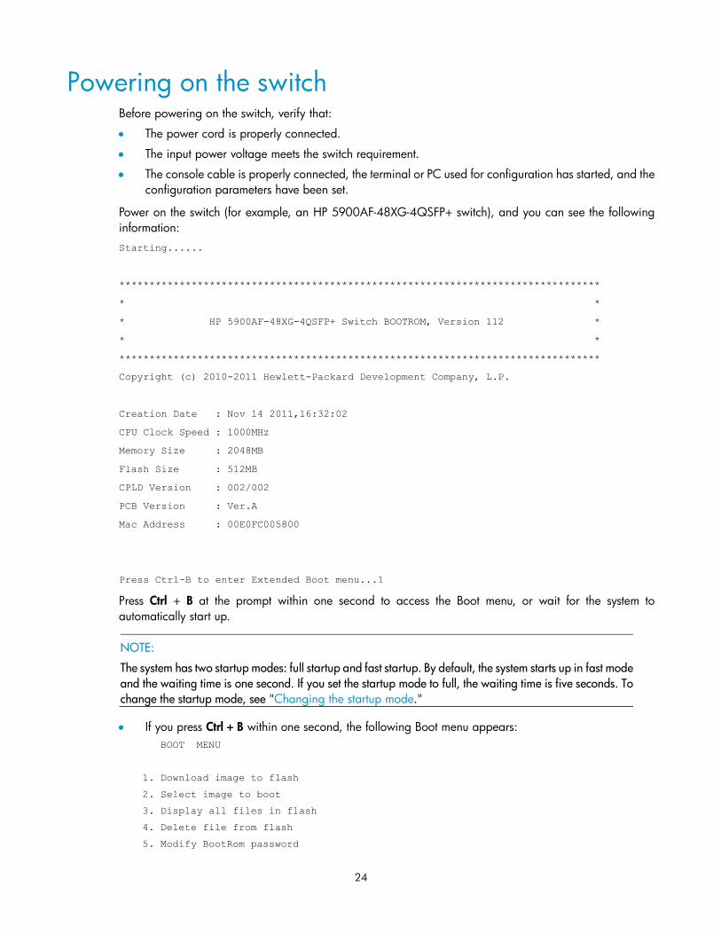
Powering on the switch for the first time ····················································································································· 20 Setting up the configuration environment ···················································································································· 20 Connecting the console cable ······································································································································ 20 Setting terminal parameters ·········································································································································· 21 Powering on the switch ················································································································································· 24
Changing the startup mode·································································································································· 26
Setting up an IRF fabric ················································································································································· 29 IRF fabric setup flowchart ·············································································································································· 29 Planning IRF fabric setup ··············································································································································· 30
Planning IRF fabric size and the installation site ································································································ 30 Identifying the master switch and planning IRF member IDs ············································································ 30 Planning IRF topology and connections ·············································································································· 31 Identifying physical IRF ports on the member switches ····················································································· 32 Planning the cabling scheme ······························································································································· 32
Configuring basic IRF settings ······································································································································ 34 Connecting the physical IRF ports ································································································································ 34 Accessing the IRF fabric to verify the configuration ··································································································· 34
iv
Maintenance and troubleshooting ······························································································································· 36 Password loss ································································································································································· 36
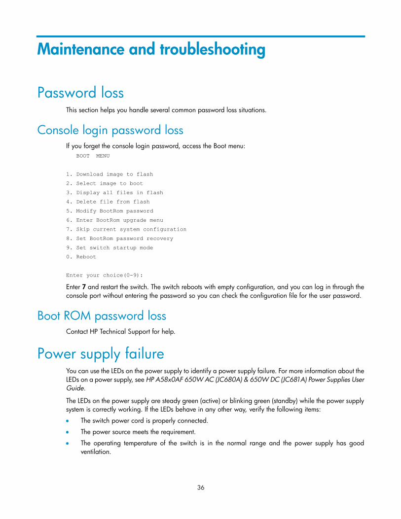
Console login password loss ······························································································································· 36 Boot ROM password loss ····································································································································· 36
Power supply failure ······················································································································································ 36 Fan failure ······································································································································································· 37 Configuration terminal problems ·································································································································· 37
Support and other resources ········································································································································ 38 Contacting HP ································································································································································ 38
Subscription service ·············································································································································· 38 Related information ························································································································································ 38
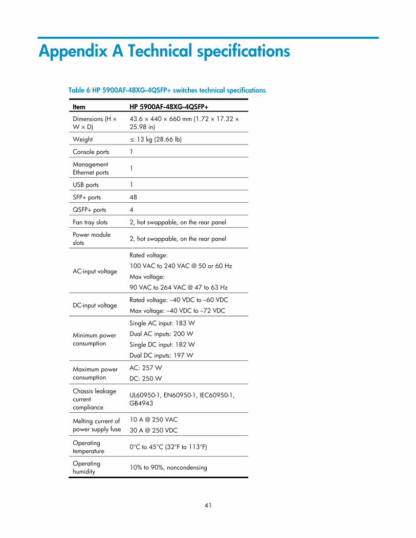
Appendix A Technical specifications··························································································································· 41 HP 5900AF-48XG-4QSFP+ panel views ····················································································································· 42
Appendix B FRUs and compatibility matrixes············································································································· 44 Hot swappable power supplies ···································································································································· 44 Hot swappable fan trays ··············································································································································· 44
Appendix C Ports and LEDs ·········································································································································· 46 Ports ················································································································································································· 46
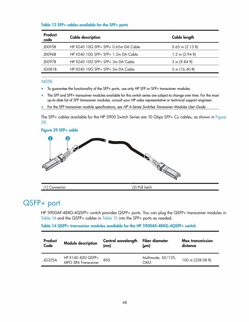
Console port ·························································································································································· 46 Management Ethernet port ··································································································································· 46 USB port ································································································································································· 46 SFP+ port ································································································································································ 47 QSFP+ port ···························································································································································· 48
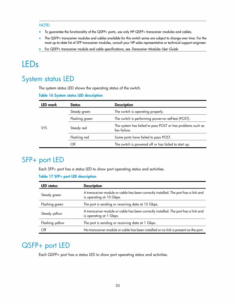
LEDs ················································································································································································· 50 System status LED ·················································································································································· 50 SFP+ port LED ························································································································································ 50 QSFP+ port LED ····················································································································································· 50 Management Ethernet port LEDs ·························································································································· 51
Appendix D Cooling system ········································································································································· 52 HP 5900AF-48XG-4QSFP+ cooling system ················································································································ 52
Index ················································································································································································ 54
1
Product overview
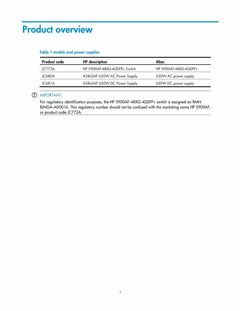
Table 1 models and power supplies
Product code HP description Alias
JC772A HP 5900AF-48XG-4QSFP+ Switch HP 5900AF-48XG-4QSFP+
JC680A A58x0AF 650W AC Power Supply 650W AC power supply
JC681A A58x0AF 650W DC Power Supply 650W DC power supply
IMPORTANT:
For regulatory identification purposes, the HP 5900AF-48XG-4QSFP+ switch is assigned an RMN
BJNGA-AD0016. This regulatory number should not be confused with the marketing name HP 5900AF,
or product code JC772A.
2
Preparing for installation
Safety recommendations
WARNING!
Read all of the safety instructions in 5900 Routing Switch Series Compliance and Safety Guide supplied
with your device before installation and operation.
To avoid any equipment damage or bodily injury caused by improper use, read the following safety
recommendations before installation. Note that the recommendations do not cover every possible hazardous
condition.
Before cleaning the switch, unplug all power cords from the switch. Do not clean the switch with wet
cloth or liquid.
Do not place the switch near water or in a damp environment. Prevent water or moisture from entering
the switch chassis.
Do not place the switch on an unstable case or desk. The switch might be severely damaged in case of
a fall.
Ensure proper ventilation of the equipment room and keep the air inlet and outlet vents of the switch free
of obstruction.
Connect the yellow-green protection grounding cable before power-on.
Make sure that the operating voltage is in the required range.
To avoid electrical shocks, do not open the chassis while the switch is operating or when the switch is
just powered off.
When replacing FRUs, including power supplies and fan trays, wear an ESD-preventive wrist strap to
avoid damaging the units.
Examining the installation site The HP 5900AF-48XG-4QSFP+ switch must be used indoors.
Mount your switch in a rack and make sure:
Adequate clearance is reserved at the air inlet and exhaust vents for ventilation.
The rack has a good ventilation system.
Identify the hot aisle and cold aisle at the installation site, and make sure that ambient air flows into the
switch from the cold aisle and exhausts to the hot aisle.
Identify the airflow designs of neighboring devices, and prevent hot air flowing out of the bottom device
from entering the top device.
The rack is sturdy enough to support the switch and its accessories.
The rack is well earthed.
To ensure normal operation and a long service life of your switch, install it in an environment that meets the
requirements described in the following subsections.
3
Temperature/humidity Maintain appropriate temperature and humidity in the equipment room.
Lasting high relative humidity can cause poor insulation, electricity creepage, mechanical property
change of materials, and metal corrosion.
Lasting low relative humidity can cause washer contraction and ESD and bring problems including
loose captive screws and circuit failure.
High temperature can accelerate the aging of insulation materials and significantly lower the reliability
and lifespan of the switch.
For the temperature and humidity requirements of different switch models, see "Support and other
resources."
Cleanness Dust buildup on the chassis may result in electrostatic adsorption, which causes poor contact of metal
components and contact points, especially when indoor relative humidity is low. In the worst case,
electrostatic adsorption can cause communication failure.
Table 2 Dust concentration limit in the equipment room
Substance Concentration limit (particles/m³)
Dust ≤ 3 x 10⁴ (no visible dust on the tabletop over three days)
NOTE:
Dust diameter ≥ 5 μm
The equipment room must also meet strict limits on salts, acids, and sulfides to eliminate corrosion and
premature aging of components, as shown in Table 3.
Table 3 Harmful gas limits in the equipment room
Gas Maximum concentration (mg/m3)
SO2 0.2
H2S 0.006
NH3 0.05
Cl2 0.01
EMI All EMI sources, from outside or inside of the switch and application system, adversely affect the switch in a
conduction pattern of capacitance coupling, inductance coupling, electromagnetic wave radiation, or
common impedance (including the grounding system) coupling. To prevent EMI, take the following actions:
If AC power is used, use a single-phase three-wire power receptacle with PE to filter interference from
the power grid.
Keep the switch far away from radio transmitting stations, radar stations, and high-frequency devices.
Use electromagnetic shielding, for example, shielded interface cables, when necessary.
4
Route interface cables only indoors to prevent signal ports from getting damaged by overvoltage or
overcurrent caused by lightning strikes.
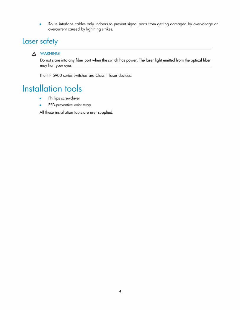
Laser safety
WARNING!
Do not stare into any fiber port when the switch has power. The laser light emitted from the optical fiber
may hurt your eyes.
The HP 5900 series switches are Class 1 laser devices.
Installation tools Phillips screwdriver
ESD-preventive wrist strap
All these installation tools are user supplied.
5
Installing the switch
CAUTION:
Keep the tamper-proof seal on a mounting screw on the chassis cover intact, and if you want to open the
chassis, contact HP for permission. Otherwise, HP shall not be liable for any consequence caused thereby.
Figure 1 Hardware installation flow
Installing the switch in a 19-inch rack
Installation prerequisites The rack depth for the HP 5900AF-48XG-4QSFP+ Switches must be 1000 mm (39.37 in).
Yes
Connect the
grounding cable
Rack-mount
the switch
Start
Connect the power
cords
Verify the installation
Power on the switch
Operating properly?
Power off the
switch
Troubleshoot the
switch
No
End
Install fan trays
Install power supplies
6
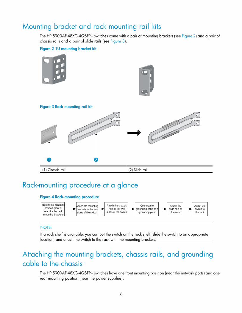
Mounting bracket and rack mounting rail kits The HP 5900AF-48XG-4QSFP+ switches come with a pair of mounting brackets (see Figure 2) and a pair of
chassis rails and a pair of slide rails (see Figure 3).
Figure 2 1U mounting bracket kit
Figure 3 Rack mounting rail kit
(1) Chassis rail (2) Slide rail
Rack-mounting procedure at a glance
Figure 4 Rack-mounting procedure
NOTE:
If a rack shelf is available, you can put the switch on the rack shelf, slide the switch to an appropriate
location, and attach the switch to the rack with the mounting brackets.
Attaching the mounting brackets, chassis rails, and grounding
cable to the chassis The HP 5900AF-48XG-4QSFP+ switches have one front mounting position (near the network ports) and one
rear mounting position (near the power supplies).
1 2
Attach the mounting
brackets to the two
sides of the switch
Identify the mounting
position (front or
rear) for the rack
mounting brackets
Attach the chassis
rails to the two
sides of the switch
Attach the
switch to
the rack
Attach the
slide rails to
the rack
Connect the
grounding cable to a
grounding point
7
Figure 5 Identifying the mounting and grounding positions of the HP 5900AF-48XG-4QSFP+
(1) Auxiliary grounding point 2 (2) Rear mounting position
(3) Primary grounding point (4) Auxiliary grounding point 1
(5) Front mounting position
Attaching the mounting brackets and chassis rails to the chassis
To attach the mounting brackets and chassis rails to the switch chassis:
1. Align the mounting brackets with the screw holes in the rear mounting position (see Figure 6) or front
mounting position (see Figure 7).
2. Use M4 screws (supplied with the switch) to attach the mounting brackets to the chassis.
3. Align the chassis rails with the rail mounting holes in the chassis:
If the mounting brackets are in the rear mounting position, align the chassis rails with the screw
holes at the front of the side panels (see Figure 6).
If the mounting brackets are in the front mounting position, align the chassis rails with the screw
holes at the rear of the side panels (see Figure 7).
4. Use M4 screws (supplied with the switch) to attach the chassis rails to the chassis.
NOTE:
Attach the mounting brackets and chassis rails to both sides of the chassis in the same way.
Connecting the grounding cable to the chassis
CAUTION:
The primary grounding point and auxiliary grounding point 1 are located on the left side panel. If you use
one of these grounding points, you must connect the grounding cable to the grounding point before you
mount the switch in the rack.
To connect the grounding cable to a chassis grounding point, for example, the primary grounding point:
1. Choose a grounding point.
2. Unpack the grounding cable and grounding screws.
You can use the cable and screws shipped with the switch only for connecting to the primary
grounding point or auxiliary grounding point 1.
1 2 3 4 5
8
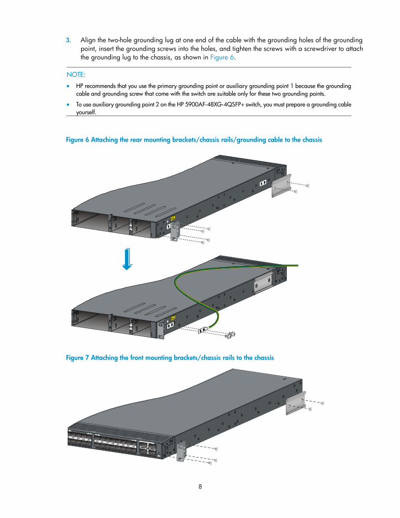
3. Align the two-hole grounding lug at one end of the cable with the grounding holes of the grounding
point, insert the grounding screws into the holes, and tighten the screws with a screwdriver to attach
the grounding lug to the chassis, as shown in Figure 6.
NOTE:
HP recommends that you use the primary grounding point or auxiliary grounding point 1 because the grounding
cable and grounding screw that come with the switch are suitable only for these two grounding points.
To use auxiliary grounding point 2 on the HP 5900AF-48XG-4QSFP+ switch, you must prepare a grounding cable
yourself.
Figure 6 Attaching the rear mounting brackets/chassis rails/grounding cable to the chassis
Figure 7 Attaching the front mounting brackets/chassis rails to the chassis
9
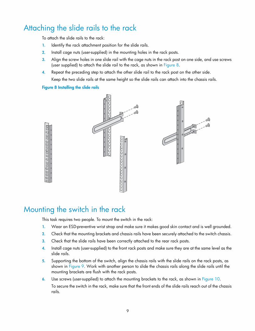
Attaching the slide rails to the rack To attach the slide rails to the rack:
1. Identify the rack attachment position for the slide rails.
2. Install cage nuts (user-supplied) in the mounting holes in the rack posts.
3. Align the screw holes in one slide rail with the cage nuts in the rack post on one side, and use screws
(user supplied) to attach the slide rail to the rack, as shown in Figure 8.
4. Repeat the preceding step to attach the other slide rail to the rack post on the other side.
Keep the two slide rails at the same height so the slide rails can attach into the chassis rails.
Figure 8 Installing the slide rails
Mounting the switch in the rack This task requires two people. To mount the switch in the rack:
1. Wear an ESD-preventive wrist strap and make sure it makes good skin contact and is well grounded.
2. Check that the mounting brackets and chassis rails have been securely attached to the switch chassis.
3. Check that the slide rails have been correctly attached to the rear rack posts.
4. Install cage nuts (user-supplied) to the front rack posts and make sure they are at the same level as the
slide rails.
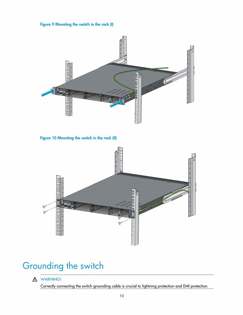
5. Supporting the bottom of the switch, align the chassis rails with the slide rails on the rack posts, as
shown in Figure 9. Work with another person to slide the chassis rails along the slide rails until the
mounting brackets are flush with the rack posts.
6. Use screws (user-supplied) to attach the mounting brackets to the rack, as shown in Figure 10.
To secure the switch in the rack, make sure that the front ends of the slide rails reach out of the chassis
rails.
10
Figure 9 Mounting the switch in the rack (I)
Figure 10 Mounting the switch in the rack (II)
Grounding the switch
WARNING!
Correctly connecting the switch grounding cable is crucial to lightning protection and EMI protection.
11
The power input end of the switch has a noise filter, whose central ground is directly connected to the chassis
to form the chassis ground (commonly known as PGND). You must securely connect this chassis ground to the
earth so the faradism and leakage electricity can be safely released to the earth to minimize EMI
susceptibility of the switch.
You can ground a switch by using a grounding strip at the installation site or the AC power cord connected
to the switch.
NOTE:
The power and grounding terminals in this section are for illustration only.
Grounding the switch with a grounding strip
WARNING!
Connect the grounding cable to the grounding system in the equipment room. Do not connect it to a fire
main or lightning rod.
If a grounding strip is available at the installation site, connect the grounding cable to the grounding strip.
To connect the grounding cable:
1. Attach the two-hole grounding lug at one end of the grounding cable to a grounding point on the
switch chassis (see "Connecting the grounding cable to the chassis").
2. Remove the hex nut of a grounding post on the grounding strip.
3. Attach the OT terminal at the other end of the grounding cable to the grounding strip through the
grounding post, and fasten the OT terminal with the removed hex nut.
Figure 11 Connecting the grounding cable to a grounding strip
(1) Hex nut (2) OT terminal
(3) Grounding post (4) Grounding strip
1 2 3 4
12
NOTE:
HP recommends that you use the primary grounding point or auxiliary grounding point 1, because the grounding
cable and grounding screw provided with the switch are applicable only to these two grounding points.
To use auxiliary grounding point 2 on the HP 5900AF-48XG-4QSFP+ switch, you must prepare a grounding cable
yourself. The connection method is the same as connecting to the other two grounding points.
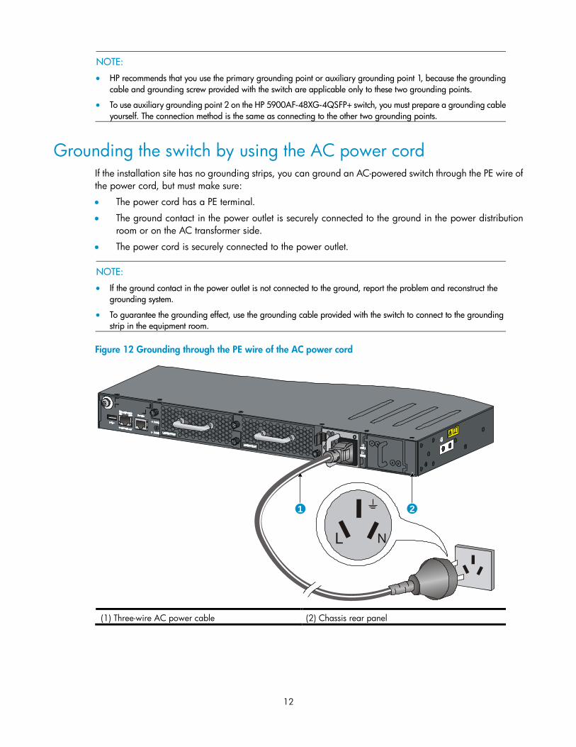
Grounding the switch by using the AC power cord If the installation site has no grounding strips, you can ground an AC-powered switch through the PE wire of
the power cord, but must make sure:
The power cord has a PE terminal.
The ground contact in the power outlet is securely connected to the ground in the power distribution
room or on the AC transformer side.
The power cord is securely connected to the power outlet.
NOTE:
If the ground contact in the power outlet is not connected to the ground, report the problem and reconstruct the
grounding system.
To guarantee the grounding effect, use the grounding cable provided with the switch to connect to the grounding
strip in the equipment room.
Figure 12 Grounding through the PE wire of the AC power cord
(1) Three-wire AC power cable (2) Chassis rear panel
1 2
13
Installing/removing a fan tray
CAUTION:
The HP 5900AF-48XG-4QSFP+ switches require two same-direction air flow fan trays to function
properly.
Do not operate the system with one failed fan tray for more than 24 hours.
Do not remove the failed fan tray until you are ready for replacing it.
Do not operate the system without any fan tray for more than 2 minutes.
Do not operate the system outside of the temperature range 0°C to 45°C (32°F to 113°F) degrees.
Failure to comply with these operating requirements may void the warranty.
Installing a fan tray
CAUTION:
To prevent damage to the fan tray or the connectors on the backplane, insert the fan tray gently. If you
encounter resistance while inserting the fan tray, pull out the fan tray and insert it again.
To install a fan tray:
1. Wear an ESD-preventive wrist strap and make sure it makes good skin contact and is well grounded.
2. Unpack the fan tray and check that the fan tray model is correct.
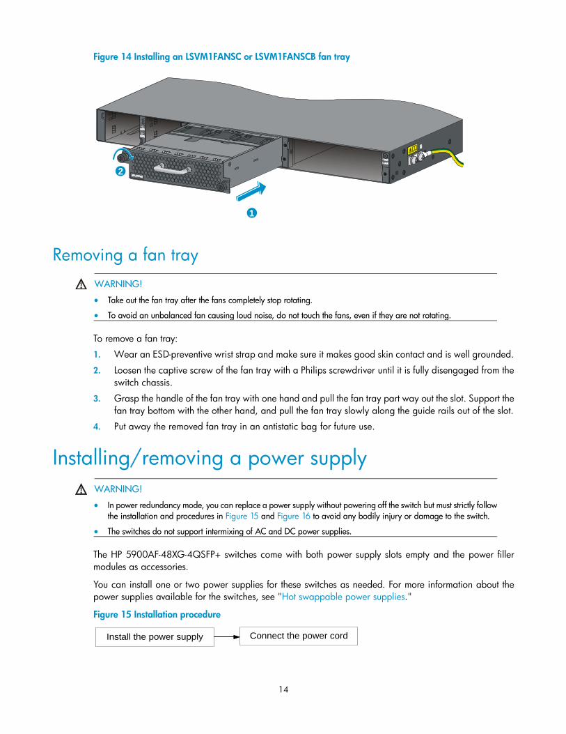
3. Grasp the handle of the fan tray with one hand and support the fan tray bottom with the other, and
slide the fan tray along the guide rails into the slot until the fan tray seats in the slot and has a firm
contact with the backplane (see callout 1 in Figure 13 or Figure 14).
4. Fasten the captive screw on the fan tray with a Philips screwdriver until the fan tray is securely attached
in the chassis (see callout 2 in Figure 13 or Figure 14).
If the captive screw cannot be tightly fastened, check the installation of the fan tray.
Figure 13 Installing an LSWM1FANSC or LSWM1FANSCB fan tray
1
2
14
Figure 14 Installing an LSVM1FANSC or LSVM1FANSCB fan tray
Removing a fan tray
WARNING!
Take out the fan tray after the fans completely stop rotating.
To avoid an unbalanced fan causing loud noise, do not touch the fans, even if they are not rotating.
To remove a fan tray:
1. Wear an ESD-preventive wrist strap and make sure it makes good skin contact and is well grounded.
2. Loosen the captive screw of the fan tray with a Philips screwdriver until it is fully disengaged from the
switch chassis.
3. Grasp the handle of the fan tray with one hand and pull the fan tray part way out the slot. Support the
fan tray bottom with the other hand, and pull the fan tray slowly along the guide rails out of the slot.
4. Put away the removed fan tray in an antistatic bag for future use.
Installing/removing a power supply
WARNING!
In power redundancy mode, you can replace a power supply without powering off the switch but must strictly follow
the installation and procedures in Figure 15 and Figure 16 to avoid any bodily injury or damage to the switch.
The switches do not support intermixing of AC and DC power supplies.
The HP 5900AF-48XG-4QSFP+ switches come with both power supply slots empty and the power filler
modules as accessories.
You can install one or two power supplies for these switches as needed. For more information about the
power supplies available for the switches, see "Hot swappable power supplies."
Figure 15 Installation procedure
1
2
Connect the power cordInstall the power supply
15
Figure 16 Removal procedure
NOTE:
The HP A58x0AF 650W AC power supply and the HP A58x0AF 650W DC power supply are referred to
as the 650W AC power supply and the 650W DC power supply throughout this installation guide.
Installing a power supply
CAUTION:
Follow the forward inertia of the power supply when inserting it into the chassis, and make sure that the power
supply has firm contact with the connectors on the backplane.
To prevent damage to the connectors inside the switch chassis, insert the power supply gently. If you encounter
resistance while inserting the power supply, pull out the power supply and insert it again.
If only one power supply is installed, install a power filler module in the empty power supply slot for good ventilation
of the switch.
To install a 650W AC power supply or 650W DC power supply into the switch:
1. Wear an ESD-preventive wrist strap and make sure it makes good skin contact and is well grounded.
2. Unpack the power supply and check that the power supply model is correct.
3. Correctly orient the power supply with the power supply slot (see Figure 17), grasp the handle of the
power supply with one hand and support its bottom with the other, and slide the power supply slowly
along the guide rails into the slot.
If you cannot insert the power supply into the slot, re-orient the power supply rather than use excessive
force to push it in.
Figure 17 Installing a power supply
Remove the power supplyDisconnect the power cord
16
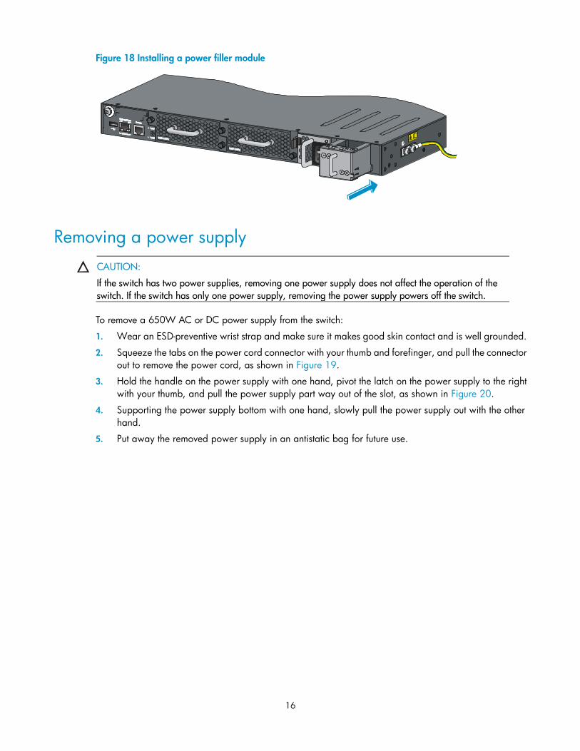
Figure 18 Installing a power filler module
Removing a power supply
CAUTION:
If the switch has two power supplies, removing one power supply does not affect the operation of the
switch. If the switch has only one power supply, removing the power supply powers off the switch.
To remove a 650W AC or DC power supply from the switch:
1. Wear an ESD-preventive wrist strap and make sure it makes good skin contact and is well grounded.
2. Squeeze the tabs on the power cord connector with your thumb and forefinger, and pull the connector
out to remove the power cord, as shown in Figure 19.
3. Hold the handle on the power supply with one hand, pivot the latch on the power supply to the right
with your thumb, and pull the power supply part way out of the slot, as shown in Figure 20.
4. Supporting the power supply bottom with one hand, slowly pull the power supply out with the other
hand.
5. Put away the removed power supply in an antistatic bag for future use.
17
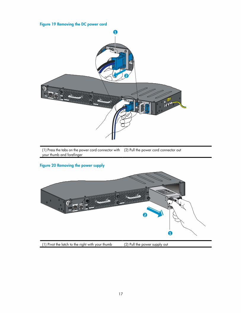
Figure 19 Removing the DC power cord
(1) Press the tabs on the power cord connector with
your thumb and forefinger
(2) Pull the power cord connector out
Figure 20 Removing the power supply
(1) Pivot the latch to the right with your thumb (2) Pull the power supply out
1
2
1
2
18
Connecting the power cord
Connecting the 650W AC power supply To connect the 650W AC power supply:
1. Insert the female connector of the AC power cord supplied with the power supply into the power
receptacle on the power supply.
2. Use a cable tie to secure the power cord to the handle of the power supply, as shown in Figure 21.
3. Connect the other end of the power cord to an AC power outlet.
Figure 21 Connecting the 650W AC power supply
(1) Cable tie
(2) Tighten the cable tie to secure the power cord to the handle of the power supply
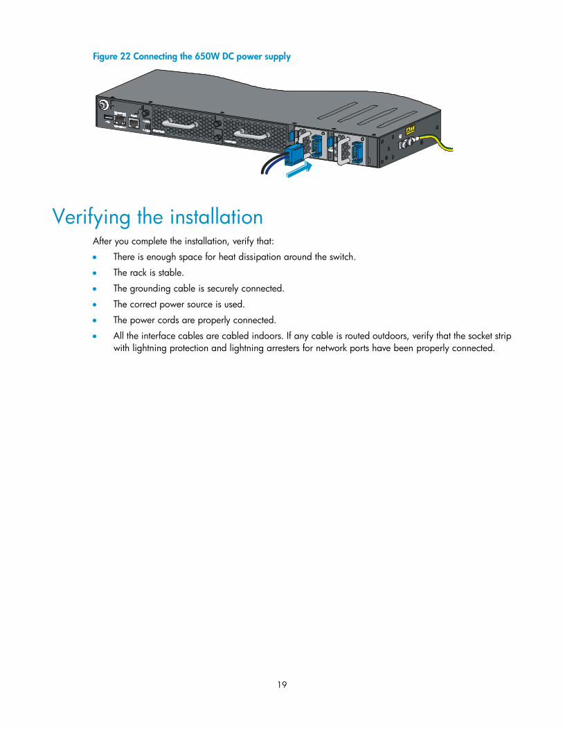
Connecting the 650W DC power supply To connect the 650W DC power supply:
1. Unpack the DC power cord, identify the plug for connecting to the power supply, orient the plug with
the power receptacle on the power supply, and insert the plug into the receptacle (see Figure 22).
If you cannot insert the plug into the receptacle, re-orient the plug rather than use excessive force to
push it in.
2. Use a cable tie to secure the power cord to the handle of the power supply, as shown in Figure 21.
3. Connect the other end of the power cord to the DC power source.
1 2
19
Figure 22 Connecting the 650W DC power supply
Verifying the installation After you complete the installation, verify that:
There is enough space for heat dissipation around the switch.
The rack is stable.
The grounding cable is securely connected.
The correct power source is used.
The power cords are properly connected.
All the interface cables are cabled indoors. If any cable is routed outdoors, verify that the socket strip
with lightning protection and lightning arresters for network ports have been properly connected.
20
Powering on the switch for the first time
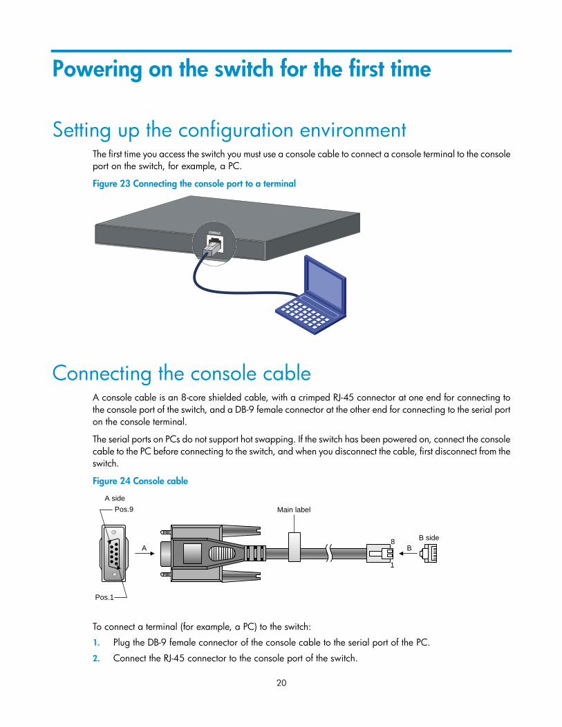
Setting up the configuration environment The first time you access the switch you must use a console cable to connect a console terminal to the console
port on the switch, for example, a PC.
Figure 23 Connecting the console port to a terminal
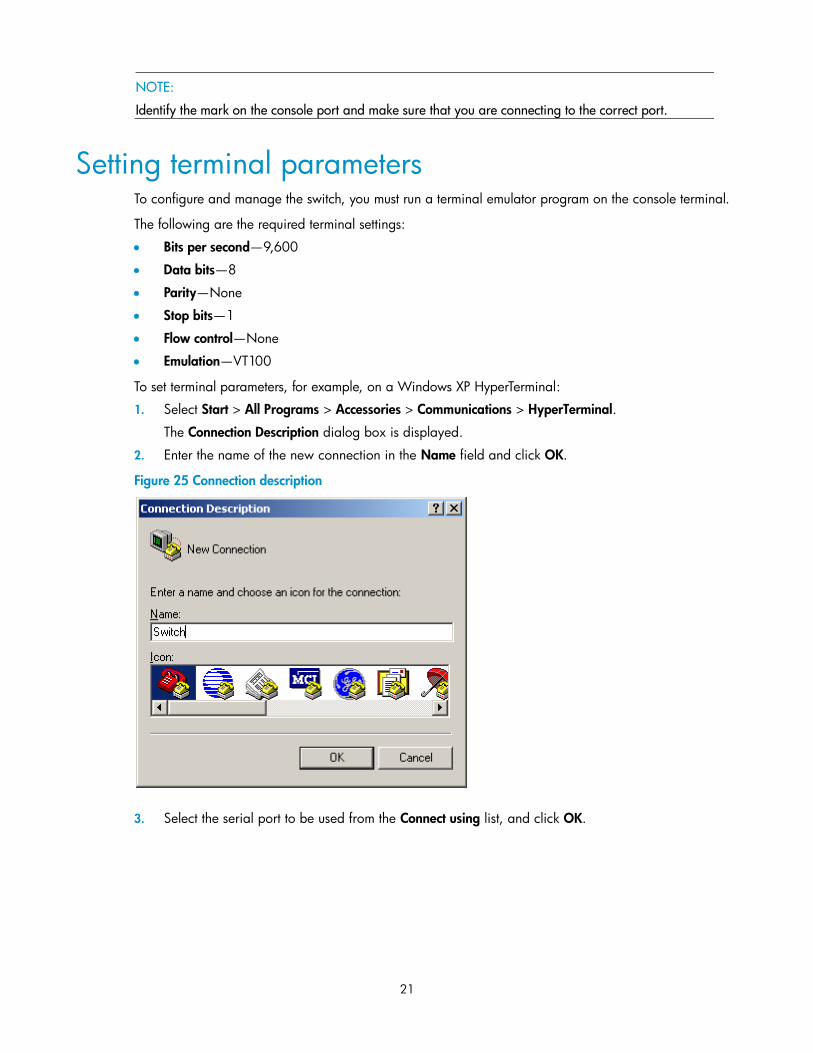
Connecting the console cable A console cable is an 8-core shielded cable, with a crimped RJ-45 connector at one end for connecting to
the console port of the switch, and a DB-9 female connector at the other end for connecting to the serial port
on the console terminal.
The serial ports on PCs do not support hot swapping. If the switch has been powered on, connect the console
cable to the PC before connecting to the switch, and when you disconnect the cable, first disconnect from the
switch.
Figure 24 Console cable
To connect a terminal (for example, a PC) to the switch:
1. Plug the DB-9 female connector of the console cable to the serial port of the PC.
2. Connect the RJ-45 connector to the console port of the switch.
Main label
1
8B side
B
Pos.9
Pos.1
A side
A
21
NOTE:
Identify the mark on the console port and make sure that you are connecting to the correct port.
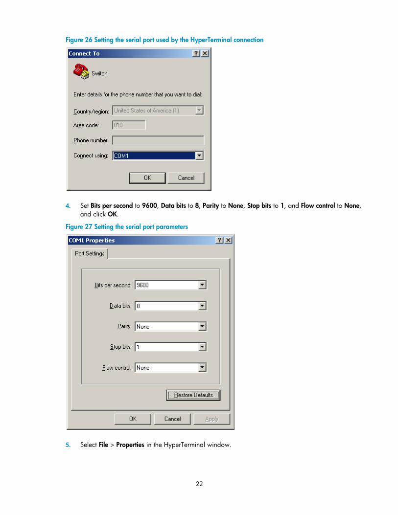
Setting terminal parameters To configure and manage the switch, you must run a terminal emulator program on the console terminal.
The following are the required terminal settings:
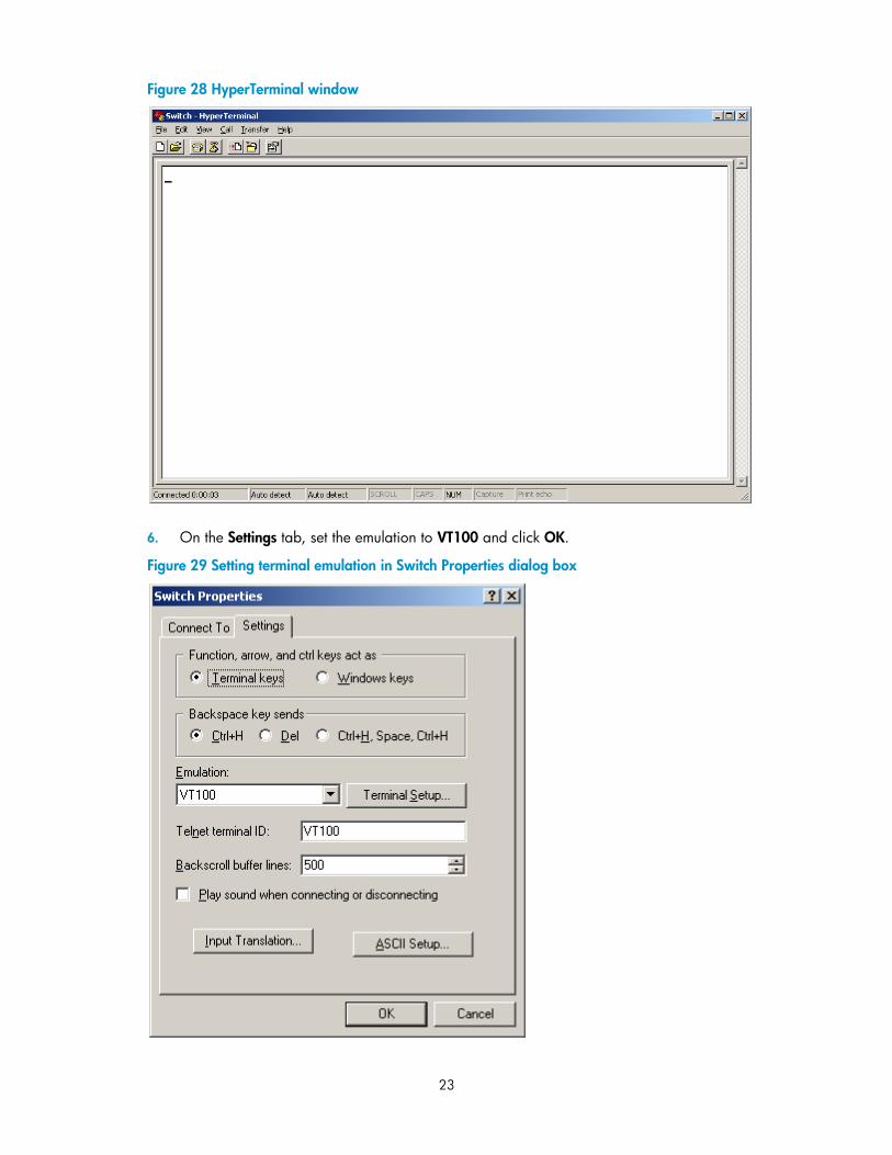
Bits per second—9,600
Data bits—8
Parity—None
Stop bits—1
Flow control—None
Emulation—VT100
To set terminal parameters, for example, on a Windows XP HyperTerminal:
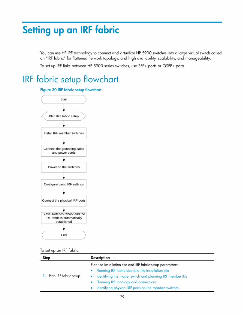
Plan the installation site and IRF fabric setup parameters:
Planning IRF fabric size and the installation site
Identifying the master switch and planning IRF member IDs
Planning IRF topology and connections
Identifying physical IRF ports on the member switches
Start
Plan IRF fabric setup
Install IRF member switches
Connect the grounding cable
and power cords
Power on the switches
Configure basic IRF settings
Connect the physical IRF ports
Slave switches reboot and the
IRF fabric is automatically
established
End
30
Step Description
Planning the cabling scheme
2. Install IRF member
switches. See "Installing the switch in a 19-inch rack".
3. Connect ground wires
and power cords. See "Grounding the switch" and "Connecting the power cord."
4. Power on the switches. N/A
5. Configure basic IRF
settings. See HP 5900 Switch Series IRF Configuration Guide.
6. Connect the physical IRF
ports.
Connect the physical IRF ports on switches. Use SFP+ or QSFP+ transceiver
modules and fibers for long-distance connection. Use SFP+ or QSFP+ cables for
short-distance connection.
All switches except the master switch automatically reboot, and the IRF fabric is
established.
Planning IRF fabric setup This section describes issues that an IRF fabric setup plan must cover.
Planning IRF fabric size and the installation site Choose switch models and identify the number of required IRF member switches, depending on the user
density and upstream bandwidth requirements. The switching capacity of an IRF fabric equals the total
switching capacities of all member switches.
Plan the installation site depending on your network solution, as follows:
Place all IRF member switches in one rack for centralized high-density access.
Distribute the IRF member switches in different racks to implement the ToR access solution for a data
center.
NOTE:
As your business grows, you can plug an HP 5900 switch into an IRF fabric to increase the switching capacity
without any topology change or replacement.
Identifying the master switch and planning IRF member IDs Determine which switch you want to use as the master for managing all member switches in the IRF fabric.
An IRF fabric has only one master switch. You configure and manage all member switches in the IRF fabric
at the command line interface of the master switch.
NOTE:
IRF member switches will automatically elect a master. You can affect the election result by assigning a
high member priority to the intended master switch. For more information about master election, see HP
5900 Switch Series IRF Configuration Guide.
Prepare an IRF member ID assignment scheme. An IRF fabric uses member IDs to uniquely identify and
manage its members, and you must assign each IRF member switch a unique member ID.
31
Planning IRF topology and connections You can create an IRF fabric in daisy chain topology, or more reliably, ring topology. In ring topology, the
failure of one IRF link does not cause the IRF fabric to split as in daisy chain topology. Rather, the IRF fabric
changes to a daisy chain topology without interrupting network services.
You connect the IRF member switches through IRF ports, the logical interfaces for the connections between
IRF member switches. Each IRF member switch has two IRF ports: IRF-port 1 and IRF-port 2. To use an IRF port,
you must bind at least one physical port to it.
When connecting two neighboring IRF member switches, you must connect the physical ports of IRF-port 1
on one switch to the physical ports of IRF-port 2 on the other switch.
The HP 5900AF-48XG-4QSFP+ switch can provide 10-GE and 40-GE IRF connections through SFP+ ports
and QSFP+ ports, respectively. You can bind several SFP+ or QSFP+ ports to an IRF port for increased
bandwidth and availability.
NOTE:
Figure 31 and Figure 32 show the topologies of an IRF fabric made up of three HP 5900AF-48XG-4QSFP+
switches that use SFP+ ports for IRF connections.
The IRF port connections in the two figures are for illustration only, and more connection methods are available.
Figure 31 IRF fabric in daisy chain topology
IRF-port1
IRF-port2
IRF-port1
IRF-port2
1 2 3
1
2
3
32
Figure 32 IRF fabric in ring topology
Identifying physical IRF ports on the member switches Identify the SFP+ or QSFP+ ports to be used for IRF connections on the member switches according to your
topology and connection scheme.
All the SFP+ and QSFP+ ports on the HP 5900AF-48XG-4QSFP+ switch can be used for IRF connections.
Follow these guidelines when you identify SFP+ ports to be used for IRF connections:
The SFP+ ports are grouped by port number in ascending order, starting from one. Every four SFP+
ports form one group.
An SFP+ port can be bound to an IRF port or operate as a service port. When an SFP+ port is bound
to an IRF port, other SFP+ ports in the same port group cannot be used as service ports, and vice versa.
A common practice is to use one SFP+ port group for IRF connections, and bind every two SFP+ ports in the
group to an IRF port for increased bandwidth and availability.
Planning the cabling scheme Use SFP+/QSFP+ cables or SFP+/QSFP+ transceiver modules and fibers to connect the IRF member
switches. If the IRF member switches are far away from one another, choose the SFP+/QSFP+ transceiver
modules with optical fibers. If the IRF member switches are all in one equipment room, choose SFP+/QSFP+
cables. For more information about available SFP+/QSFP+ cables and transceiver modules, see "SFP+ port"
and "QSFP+ port."
The following subsections describe several HP recommended IRF connection schemes, and all these schemes
use a ring topology.
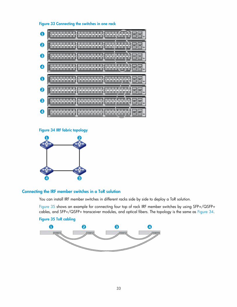
Connecting the IRF member switches in one rack
Use short-haul and long-haul SFP+ cables to connect the IRF member switches (four switches in this example)
in a rack as shown in Figure 33. The switches in the ring topology (see Figure 34) are in the same order as
connected in the rack.
IRF-port1
IRF-port2
IRF-port1
IRF-port1
IRF-port2
IRF-port2
1
2
3
1
2 3
33
Figure 33 Connecting the switches in one rack
Figure 34 IRF fabric topology
Connecting the IRF member switches in a ToR solution
You can install IRF member switches in different racks side by side to deploy a ToR solution.
Figure 35 shows an example for connecting four top of rack IRF member switches by using SFP+/QSFP+
cables, and SFP+/QSFP+ transceiver modules, and optical fibers. The topology is the same as Figure 34.
Figure 35 ToR cabling
1
2
3
4
1
2
3
4
1 2
34
1 2 3 4
34
Configuring basic IRF settings After you install the IRF member switches, power on the switches, and log in to each IRF member switch (see
HP 5900 Switch Series Fundamentals Configuration Guide) to configure their member IDs, member priorities,
and IRF port bindings.
Follow these guidelines when you configure the switches:
Assign the master switch higher member priority than any other switch.
Bind physical ports to IRF port 1 on one switch and to IRF port 2 on the other switch. Perform IRF port
binding before or after connecting IRF physical ports depending on the software release.
Execute the display irf configuration command to verify the basic IRF settings.
For more information about configuring basic IRF settings, see HP 5900 Switch Series IRF Configuration
Guide.
Connecting the physical IRF ports Use SFP+/QSFP+ cables or SFP+/QSFP+ transceiver modules and fibers to connect the IRF member
switches as planned.
NOTE:
Wear an ESD-preventive wrist strap when you connect SFP+ cables or SFP+ transceiver modules and
fibers. For how to connect them, see SFP/SFP+/XFP Transceiver Modules Installation Guide and QSFP+
Transceiver Modules/Cables Installation Guide.
Accessing the IRF fabric to verify the configuration To verify the basic functionality of the IRF fabric after you finish configuring basic IRF settings and connecting
IRF ports:
1. Log in to the IRF fabric through the console port of any member switch.
2. Create a Layer 3 interface, assign it an IP address, and make sure that the IRF fabric and the remote
network management station can reach each other.
3. Use Telnet, web, or SNMP to access the IRF fabric from the network management station. (See HP
5900 Switch Series Fundamentals Configuration Guide.)
4. Check that you can manage all member switches as if they were one node.
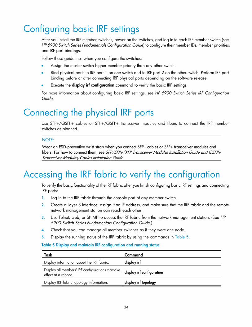
5. Display the running status of the IRF fabric by using the commands in Table 5.
Table 5 Display and maintain IRF configuration and running status
Task Command
Display information about the IRF fabric. display irf