HP A3100 v2 Switch Series Installation Guide HP A3100-8 v2 SI Switch (JG221A) HP A3100-16 v2 SI Switch (JG222A) HP A3100-24 v2 SI Switch (JG223A) HP A3100-8 v2 EI Switch (JD318B) HP A3100-16 v2 EI Switch (JD319B) HP A3100-24 v2 EI Switch (JD320B) HP A3100-8-PoE v2 EI Switch (JD311B) HP A3100-16-PoE v2 EI Switch (JD312B) HP A3100-24-PoE v2 EI Switch (JD313B) Part number: 5998-1961 Document version: 6W100-20110909
A3100-24 v2 SI/A3100-24 v2 EI ························································································································· 1 A3100-16 v2 SI/A3100-16 v2 EI ························································································································· 2 A3100-8 v2 SI/A3100-8 v2 EI ······························································································································ 3 A3100-24-PoE v2 EI ················································································································································ 3 A3100-16-PoE v2 EI ················································································································································ 4 A3100-8-PoE v2 EI ··················································································································································· 5
Preparing for installation ················································································································································· 7 Safety recommendations ·················································································································································· 7 Examining the installation site ········································································································································· 7
Installing the switch ························································································································································ 12 Installing the switch ························································································································································ 12
Selecting an installation method ·························································································································· 12 Installation accessories ········································································································································· 13 Installing the switch into the 19-inch rack ··········································································································· 15 Mounting the switch on a workbench ················································································································· 20
Grounding the switch ···················································································································································· 21 Grounding cable ··················································································································································· 21 Grounding the switch with a grounding strip····································································································· 21 Grounding the switch with a grounding conductor buried in the earth ground············································· 23 Grounding the switch by using the AC power cord ·························································································· 24
Connecting the power cord ·········································································································································· 24 Connecting an AC power cord to the switch ····································································································· 24 Connecting the DC power cord ··························································································································· 25
Verifying the installation ················································································································································ 26
Accessing the switch for the first time ·························································································································· 27 Setting up the configuration environment ···················································································································· 27 Connecting the console cable ······································································································································ 27
Setting terminal parameters ·········································································································································· 28 Powering on the switch ················································································································································· 31
Verification before power-on ······························································································································· 31 Powering on the switch ········································································································································· 31
Initially configuring the switch ······································································································································ 32 Configuring a login authentication method ········································································································ 32
ii
Configuring the basic access function ················································································································ 33
Connecting the switch to the network ·························································································································· 34 Connecting your switch to the network through twisted pair cables ········································································ 34 Connecting your switch to the network through optical fibers ·················································································· 34
Installing an SFP transceiver module ··················································································································· 35 Connecting an optical fiber connector to an SFP transceiver module ····························································· 35
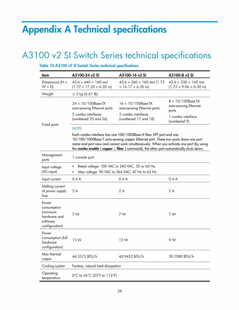
Appendix A Technical specifications··························································································································· 39 A3100 v2 SI Switch Series technical specifications ·································································································· 39 A3100 v2 EI Switch Series technical specifications ·································································································· 40
Appendix B Ports and LEDs ·········································································································································· 44 Ports ················································································································································································· 44
Console port ·························································································································································· 44 10/100Base-TX Ethernet port ······························································································································ 44 Combo interface ···················································································································································· 44 10/100/1000Base-T Ethernet port ···················································································································· 45 100/1000Base-X SFP port ·································································································································· 45
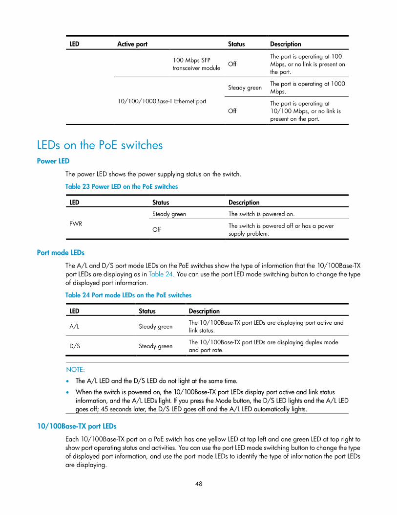
LEDs ················································································································································································· 46 LEDs for the non PoE switches ······························································································································ 47 LEDs on the PoE switches ······································································································································ 48
RJ-45 connector ····················································································································································· 50 Cable pinouts ························································································································································· 50 Cable type ····························································································································································· 50 Pin assignments ····················································································································································· 52 Making an Ethernet twisted pair cable ··············································································································· 53
Index ················································································································································································ 54
1
Product overview
Switch models Table 1 Switch models in the HP A3100 v2 Switch Series
Sub-series Model Product code Description Alias
HP A3100 v2 SI
Switch Series
Non
PoE
JG221A HP A3100-8 v2 SI Switch A3100-8 v2 SI
JG222A HP A3100-16 v2 SI Switch A3100-16 v2 SI
JG223A HP A3100-24 v2 SI Switch A3100-24 v2 SI
HP A3100 v2 EI
Switch Series
Non
PoE
JD318B HP A3100-8 v2 EI Switch A3100-8 v2 EI
JD319B HP A3100-16 v2 EI Switch A3100-16 v2 EI
JD320B HP A3100-24 v2 EI Switch A3100-24 v2 EI
PoE
JD311B HP A3100-8-PoE v2 EI Switch A3100-8-PoE v2 EI
JD312B HP A3100-16-PoE v2 EI Switch A3100-16-PoE v2 EI
JD313B HP A3100-24-PoE v2 EI Switch A3100-24-PoE v2 EI
Panel views
A3100-24 v2 SI/A3100-24 v2 EI Front panel
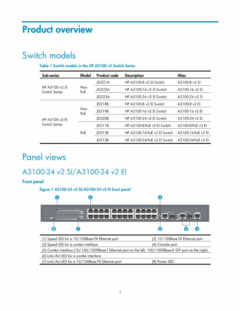
Figure 1 A3100-24 v2 SI/A3100-24 v2 EI front panel
1 2 3
45678
(1) Speed LED for a 10/100Base-TX Ethernet port (2) 10/100Base-TX Ethernet port
(3) Speed LED for a combo interface (4) Console port
(5) Combo interface (10/100/1000Base-T Ethernet port on the left, 100/1000Base-X SFP port on the right)
(6) Link/Act LED for a combo interface
(7) Link/Act LED for a 10/100Base-TX Ethernet port (8) Power LED
2
Rear panel
Figure 2 A3100-24 v2 SI/A3100-24 v2 EI rear panel
1 2
(1) Grounding screw (2) AC-input power receptacle
A3100-16 v2 SI/A3100-16 v2 EI Front panel
Figure 3 A3100-16 v2 SI/A3100-16 v2 EI front panel
1 2 3
45678
(1) Speed LED for a 10/100Base-TX Ethernet port (2) 10/100Base-TX Ethernet ports
(3) Speed LED for a combo interface (4) Console port
(5) Combo interface (10/100/1000Base-T Ethernet port on the left, 100/1000Base-X SFP port on the right)
(6) Link/Act LED for a combo interface (7) Link/Act LED for a 10/100Base-TX Ethernet port
(8) Power LED
Rear panel
Figure 4 A3100-16 v2 SI/A3100-16 v2 EI rear panel
1 2
(1) Grounding screw (2) AC-input power receptacle
3
A3100-8 v2 SI/A3100-8 v2 EI Front panel
Figure 5 A3100-8 v2 SI/A3100-8 v2 EI front panel
1 2 3
45678
(1) Speed LED for a 10/100Base-TX Ethernet port (2) 10/100Base-TX Ethernet ports
(3) Speed LED for a combo interface (4) Console port
(5) Combo interface (10/100/1000Base-T Ethernet port on the left, 100/1000Base-X SFP port on the right)
(6) Link/Act LED for a combo interface (7) Link/Act LED for a 10/100Base-TX Ethernet port
(8) Power LED
Rear panel
Figure 6 A3100-8 v2 SI/A3100-8 v2 EI rear panel
1 2
(1) Grounding screw (2) AC-input power receptacle
A3100-24-PoE v2 EI Front panel
Figure 7 A3100-24-PoE v2 EI front panel
1 2 3 4 5 6
7
8
910
(1) 10/100Base-TX Ethernet port
(2) 10/100Base-TX Ethernet port LEDs (left: yellow, right: green)
(3) Combo interface (10/100/1000Base-T Ethernet port on the left, 100/1000Base-X SFP port on the right)
4
(4) LINK LED for a combo interface (5) Console port
(6) Port LED mode switching (Mode) button (7) Power (PWR) LED
(8) Port mode (A/L) LED (9) Port mode (D/S) LED
(10) ACT LED for a combo interface
Rear panel
Figure 8 A3100-24-PoE v2 EI rear panel
1 2
3
(1) AC-input power receptacle (2) DC-input terminal block
(3) Grounding screw
A3100-16-PoE v2 EI Front panel
Figure 9 A3100-16-PoE v2 EI front panel
1 2 3 4 5 6
7
8
910
(1) 10/100Base-TX Ethernet port (2) 10/100Base-TX Ethernet port LEDs (left: yellow, right: green)
(3) Combo interface (10/100/1000Base-T Ethernet port on the left, 100/1000Base-X SFP port on the right)
(4) LINK LED for a combo interface (5) Console port
(6) Port LED mode switching (Mode) button (7) Power (PWR) LED
(8) Port mode (A/L) LED (9) Port mode (D/S) LED
(10) ACT LED for a combo interface
5
Rear panel
Figure 10 A3100-16-PoE v2 EI rear panel
1
2
(1) AC-input power receptacle (2) DC-input terminal block
(3) Grounding screw
A3100-8-PoE v2 EI Front panel
Figure 11 A3100-8-PoE v2 EI front panel
1 2 3 4 5 6
7
8
910
(1) 10/100Base-TX Ethernet port
(2) 10/100Base-TX Ethernet port LEDs (left: yellow, right: green)
(3) Combo interface (10/100/1000Base-T Ethernet port on the left, 100/1000Base-X SFP port on the right)
(4) LINK LED for a combo interface (5) Console port
(6) Port LED mode switching (Mode) button (7) Power (PWR) LED
(8) Port mode (A/L) LED (9) Port mode (D/S) LED
(10) ACT LED for a combo interface
Rear panel
Figure 12 A3100-8-PoE v2 EI rear panel
后面板
1
2
(1) AC-input power receptacle (2) Grounding screw
6
Right side panel
The A3100-8-PoE v2 EI switch has one security lock slot on the right-side panel to prevent theft. You must
purchase a cable lock separately.
Figure 13 A3100-8-PoE v2 EI left side panel
1
(1) Security lock slot
7
Preparing for installation
Safety recommendations To avoid any equipment damage or bodily injury caused by improper use, read the following safety
recommendations before installation. Note that the recommendations do not cover every possible hazardous
condition.
Before cleaning the switch, unplug all power cords from the switch. Do not clean the switch with wet
cloth or liquid.
Do not place the switch near water or in a damp environment. Prevent water or moisture from entering
the switch chassis.
Make sure that the ground is dry and flat and anti-slip measures are in place.
Do not place the switch on an unstable case or desk. The switch might be severely damaged in case of
a fall.
Keep the chassis and installation tools away from walk areas.
Do not wear loose clothing, jewelry (for example, necklace), or any other objects that could get caught
in the chassis when you install and maintain the switch.
To avoid electrical shocks, do not open the chassis while the switch is operating or when the switch is
just powered off.
Examining the installation site The A3100 v2 Switch Series must be used indoors. To ensure normal operation and long service life of your
switch, install it in an environment that meets the requirements described in the following subsections.
Electricity safety Clear the work area of possible hazards, such as ungrounded power extension cables, missing safety
grounds, and wet floors.
Make sure that the operating voltage is as required.
Locate the emergency power-off switch in the room before installation. Shut the power off at once in
case accident occurs.
Unplug all the external cables (including power cords) before moving the chassis.
Always check that the power has been disconnected.
ESD prevention To prevent the electronic components from being damaged by the electrostatic discharge (ESD), you should
not only take ESD measures where the switch is located, but also take the following precautions:
Make sure the switch is well grounded. For how to ground the switch, see ―Grounding the switch.‖
Always wear an ESD-preventive wrist strap when installing hot swappable modules.
To use the ESD-preventive wrist strap:
8
1. Wear the wrist strap on your wrist.
2. Lock the wrist strap tight around your wrist to keep good contact with the skin.
3. Attach the ESD-preventive wrist strap to a post on the rack or ground it by using other methods.
Figure 14 Use an ESD-preventive wrist strap
1
(1) Rack post
Laser safety The A3100 v2 switches are Class 1 laser devices.
WARNING!
Do not stare into any fiber port when the switch has power. The laser light emitted from the optical fiber
may hurt your eyes.
Temperature/humidity Maintain appropriate temperature and humidity in the equipment room.
Lasting high relative humidity can cause poor insulation, electricity creepage, mechanical property
change of materials, and metal corrosion.
Lasting low relative humidity can cause washer contraction and ESD and bring problems including
loose captive screws and circuit failure.
High temperature can accelerate the aging of insulation materials and significantly lower the reliability
and lifespan of the switch.
Table 2 Temperature requirements
Temperature Range
Operating temperature 0°C to 45°C (32°F to 113°F)
Storage temperature –40°C to +70°C (–40°F to +158°F)
9
CAUTION:
If condensation appears on the switch when you move it to a high-temperature environment, dry the switch
before powering it on to avoid short circuits.
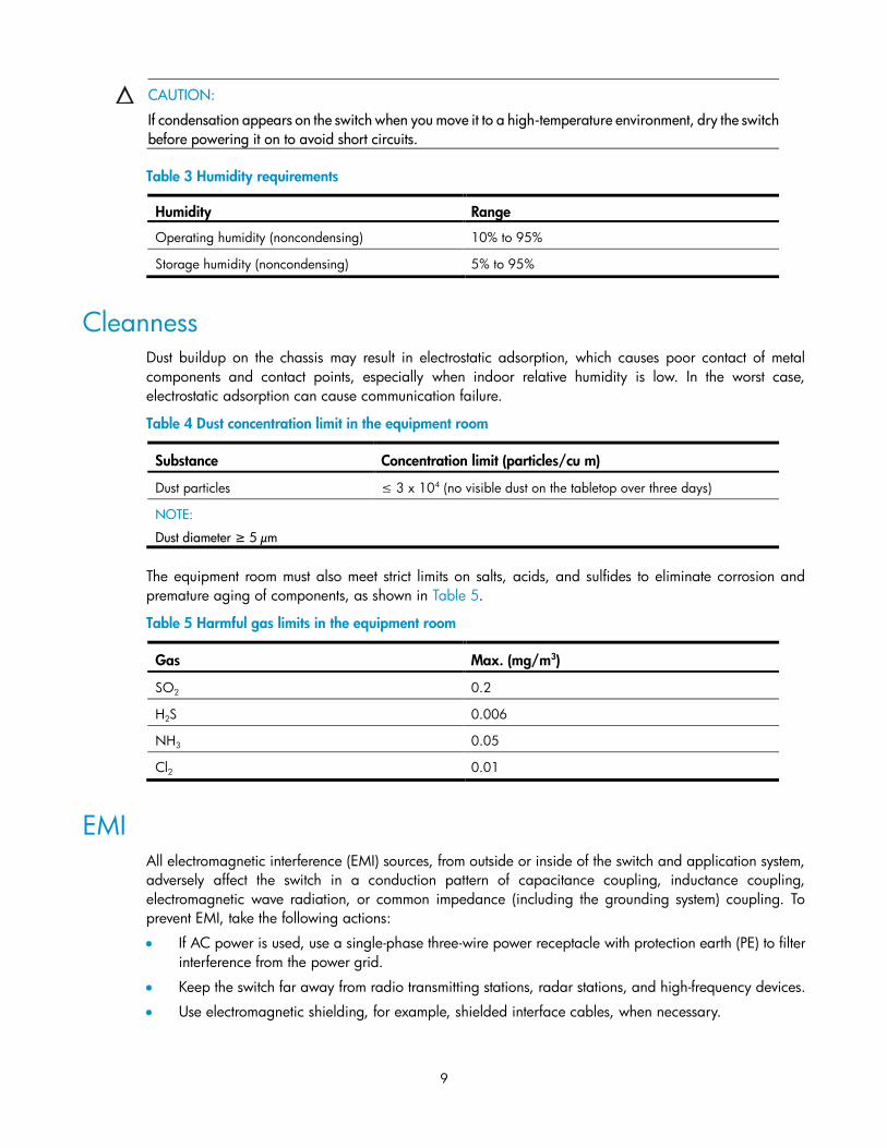
Table 3 Humidity requirements
Humidity Range
Operating humidity (noncondensing) 10% to 95%
Storage humidity (noncondensing) 5% to 95%
Cleanness Dust buildup on the chassis may result in electrostatic adsorption, which causes poor contact of metal
components and contact points, especially when indoor relative humidity is low. In the worst case,
electrostatic adsorption can cause communication failure.
Table 4 Dust concentration limit in the equipment room
Substance Concentration limit (particles/cu m)
Dust particles ≤ 3 x 10⁴ (no visible dust on the tabletop over three days)
NOTE:
Dust diameter ≥ 5 µm
The equipment room must also meet strict limits on salts, acids, and sulfides to eliminate corrosion and
premature aging of components, as shown in Table 5.
Table 5 Harmful gas limits in the equipment room
Gas Max. (mg/m3)
SO2 0.2
H2S 0.006
NH3 0.05
Cl2 0.01
EMI All electromagnetic interference (EMI) sources, from outside or inside of the switch and application system,
adversely affect the switch in a conduction pattern of capacitance coupling, inductance coupling,
electromagnetic wave radiation, or common impedance (including the grounding system) coupling. To
prevent EMI, take the following actions:
If AC power is used, use a single-phase three-wire power receptacle with protection earth (PE) to filter
interference from the power grid.
Keep the switch far away from radio transmitting stations, radar stations, and high-frequency devices.
Use electromagnetic shielding, for example, shielded interface cables, when necessary.
10
Route interface cables only indoors to prevent signal ports from getting damaged by overvoltage or
overcurrent caused by lightning strikes.
Grounding Using a good grounding system to protect your switch against lightning shocks, interferences, and ESD is
essential to the operating reliability of your switch. Make sure that the resistance between the chassis and
ground is less than 1.5 ohm. For more information about grounding the A3100 v2 Switch Series, see
―Grounding the switch.‖
Cooling The cooling system of the A3100 v2 Switch Series varies by the switch model:
Non PoE switches (fanless): There are openings on the left, right, and rear of the switch for natural heat
dissipation.
PoE switches (built-in fans): Fans blow air from the left to the right of the chassis for heat dissipation. See
Figure 15.
Figure 15 Airflow through a PoE switch
1
2
(1) Air intake (2) Air exhaust
For adequate heat dissipation, plan the installation site according to the airflow of your switch, and adhere
to the following requirements:
Leave a clearance of at least 10 cm (3.94 in) around the air intake and exhaust vents.
Consider the heat dissipation of the installation site when determining air-conditioning requirements to
ensure that cool air can enter the switch.
Make sure the hot air generated by equipment at the bottom of the rack is not drawn in the intake of the
equipment above.
The installation site has a good cooling system.
Space For adequate ventilation and ease of maintenance, adhere to the following requirements:
The clearance between the rack and walls or other devices is at least 1 m (3.28 ft).
The headroom in the equipment room is no less than 3 m (9.84 ft).
11
Installation tools Table 6 Tool list
Category Tool
Measuring and marking tools Long tape, ruler of 1 m (3.28 ft), gradienter, marker, chalk line, and pencil
Drills Percussion drill, electric drill, and several auxiliary drill bits
Fastening tools
Flat-blade screwdriver P4-75 mm
Phillips screwdriver P1-100 mm, P2-150 mm, and P3-250 mm
Socket wrench M5
Socket wrench M6
Small tools Needle-nose pliers, diagonal pliers, combination pliers, wire-stripping pliers,
crimping pliers, RJ-45 crimping pliers
Auxiliary tools
ESD-preventive wrist strap, hair brush, tweezers, paper knife, hand bellows,
electric iron, solder wire, ladder, cable stripper, vacuum cleaner, crowbar,
rubber hammer, and blower
Tools for fiber-optic cleaning Lint-free paper and optical fiber microscope
Equipment Multimeter, 500 V Megohmmeter for measuring the insulation resistance,
error detector, optical power meter, and earth resistance tester
NOTE:
Tools and equipment are not supplied with the switch. Prepare them yourself as needed.
12
Installing the switch
CAUTION:
Keep the tamper-proof seal on a mounting screw on the chassis cover intact, and if you want to open the
chassis, contact the local agent of HP for permission. Otherwise, HP shall not be liable for any
consequence caused thereby.
Figure 16 Hardware installation flow
Ground the switch
Install the switch
to a specific
position
Start
Connect the power cord
Verify the installation
Power on the switch
Operating properly? Power off the switch
Troubleshoot
the switch
No
Yes
End
Installing the switch
Selecting an installation method The A3100 v2 Switch Series supports multiple installation methods. You can select one as needed.
Table 7 A3100 v2 Switch Series installation methods
Switch model Installation methods Installation accessories
A3100-24 v2 SI
A3100-24 v2 EI
Installing the switch into the
19-inch rack (Rack mounting by
using front mounting brackets)
Front mounting bracket. See callout A in
Figure 17 (supplied with the switch).
13
Switch model Installation methods Installation accessories
Mounting the switch on a
workbench
Rubber pad: See Figure 19 (supplied
with the switch).
A3100-16 v2 SI
A3100-16 v2 EI
Installing the switch into the
19-inch rack (Rack mounting by
using front mounting brackets)
Front mounting bracket: HP A3100-16
Rack Mount Kit (JD321A).
See callout C in Figure 17 (optional).
Mounting the switch on a
workbench Rubber pad: See Figure 19 (supplied
with the switch).
A3100-8 v2 SI
A3100-8 v2 EI
Installing the switch into the
19-inch rack (Rack mounting by
using front mounting brackets)
Front mounting bracket: HP A3100-8
Rack Mount Kit (JD322A).
See callout B in Figure 17 (optional).
Mounting the switch on a
workbench
Rubber pad: See Figure 19 (supplied
with the switch).
A3100-24-PoE v2 EI
Installing the switch into the
19-inch rack (Rack mounting by
using front and rear mounting
brackets)
Front mounting bracket. See callout A in
Figure 17 (supplied with the switch).
Rear mounting bracket: See Figure 18
(supplied with the switch).
Mounting the switch on a
workbench Rubber pad: See Figure 19 (supplied
with the switch).
A3100-16-PoE v2 EI
A3100-8-PoE v2 EI
Installing the switch into the
19-inch rack (Rack mounting by
using front mounting brackets)
Front mounting bracket: HP
A3100-16-PoE and 8-PoE Rack Mount
Kit (JD323A).
See callout D in Figure 17 (optional).
Mounting the switch on a
workbench Rubber pad: See Figure 19 (supplied
with the switch).
Installation accessories Mounting brackets for rack mounting
The A3100 v2 Switch Series provides different mounting brackets for different models. Select them as
required.
14
Figure 17 Front mounting brackets
(A) (B:JD322A)
(C:JD321A) (D:JD323A)
1
2
3
1
2
3
1
2
3
1
2
3
(1) Screw hole (for M6 screw) for fixing the front mounting bracket to the rack
(2) Screw hole for fixing the front mounting bracket to the switch
(3) M4 screws for fixing the front mounting bracket to the switch
Figure 18 Rear mounting bracket
1
2
(1) Screw hole (for M6 screw) for fixing the rear mounting bracket to the rack
(2) Load-bearing screw (installed to the switch)
15
Rubber pads
Each A3100 v2 switch provides four rubber pads, as shown in Figure 19. Before mounting the switch to a
workbench, attach the four rubber pads to the switch bottom first.
Figure 19 Rubber pad appearance
1
(1) Rubber pad
Installing the switch into the 19-inch rack
CAUTION:
Ensure a clearance of 1U (44.45 mm, or 1.75 in) between equipment for heat dissipation.
For a switch with a depth greater than 300 mm (11.81 in), the front mounting brackets only secure the
switch rather than bear its weight. To mount this switch to a rack, you need to use front mounting
brackets and other accessories. For example, use front mounting brackets and rear mounting brackets
(for more information, see “Rack mounting by using front and rear mounting brackets.”), or use front
mounting brackets and a rack shelf (if there is a rack shelf on the rack, put the switch on the rack shelf,
move the switch to an appropriate position, and fix the switch by using front mounting brackets.).
Rack mounting by using front mounting brackets
NOTE:
The installation procedures for front mounting brackets with different length are similar. The following uses
front mounting brackets supplied with the switch as an example.
To install the switch to the rack by using front mounting brackets:
1. Wear an ESD-preventive wrist strap and make sure it makes good skin contact and is well grounded,
check that the rack is sturdy and well grounded.
2. Unpack the screws (packed with the front mounting brackets), and install the front mounting brackets
to the switch with the screws. See Figure 20.
16
Figure 20 Install the front mounting brackets
1
(1) Chassis front panel
3. Determine where to install the switch in the rack, and install the cage nuts to the corresponding
positions on the front rack posts.
4. Supporting the bottom of the switch, move the switch to the appropriate position. Have another person
to install the mounting brackets to the rack posts with the M6 screws. See Figure 21.
Figure 21 Mount the switch to the rack by using front mounting brackets
1
2
3
1
(1) Front rack posts (2) Chassis front panel (3) Front mounting bracket
Rack mounting by using front and rear mounting brackets
To mount the switch to the rack by using front and rear mounting brackets:
1. Wear an ESD-preventive wrist strap and make sure it makes good skin contact and is well grounded.
2. Check that the rack is sturdy and well grounded.
17
3. Unpack the screws (packed with the front mounting brackets), and install the front mounting brackets
to the switch with the screws. See Figure 20.
4. Unpack the load-bearing screws (packed with the rear mounting brackets), and install them to the
appropriate positions on the two sides of the switch. See Figure 22.
Figure 22 Rack mounting by using front and rear mounting brackets
1
2
3
45
(1) Load-bearing screw
(2) Load-bearing screw positions (select one as needed)
(3) Chassis front panel (4) Front mounting bracket
(5) Screw (packaged with the front mounting bracket) for fixing the front mounting bracket to the switch
NOTE:
The switch provides three positions on both sides to mount a load-bearing screw. Select a proper position
according to the actual requirements. The rear mounting brackets support the switch by the load-bearing
screws.
5. Determine where to install the switch to the rack, and install the cage nuts to the corresponding
positions on the front and rear rack posts.
6. Fix the rear mounting brackets to the rear rack posts by using the M6 screws. See Figure 23.
18
Figure 23 Mount the switch to the rack by using rear mounting brackets
1
2
1
(1) Rack posts (2) Rear mounting bracket
CAUTION:
Make sure the thinner edge of the rear mounting bracket faces upwards to ensure that the mounting
bracket can make close contact with the load-bearing screws.
7. Supporting the switch bottom with one hand, use the other hand to push the switch into the rack until
the load-bearing screws on the switch make close contact with the upper edge of the rear mounting
bracket. See Figure 24.
19
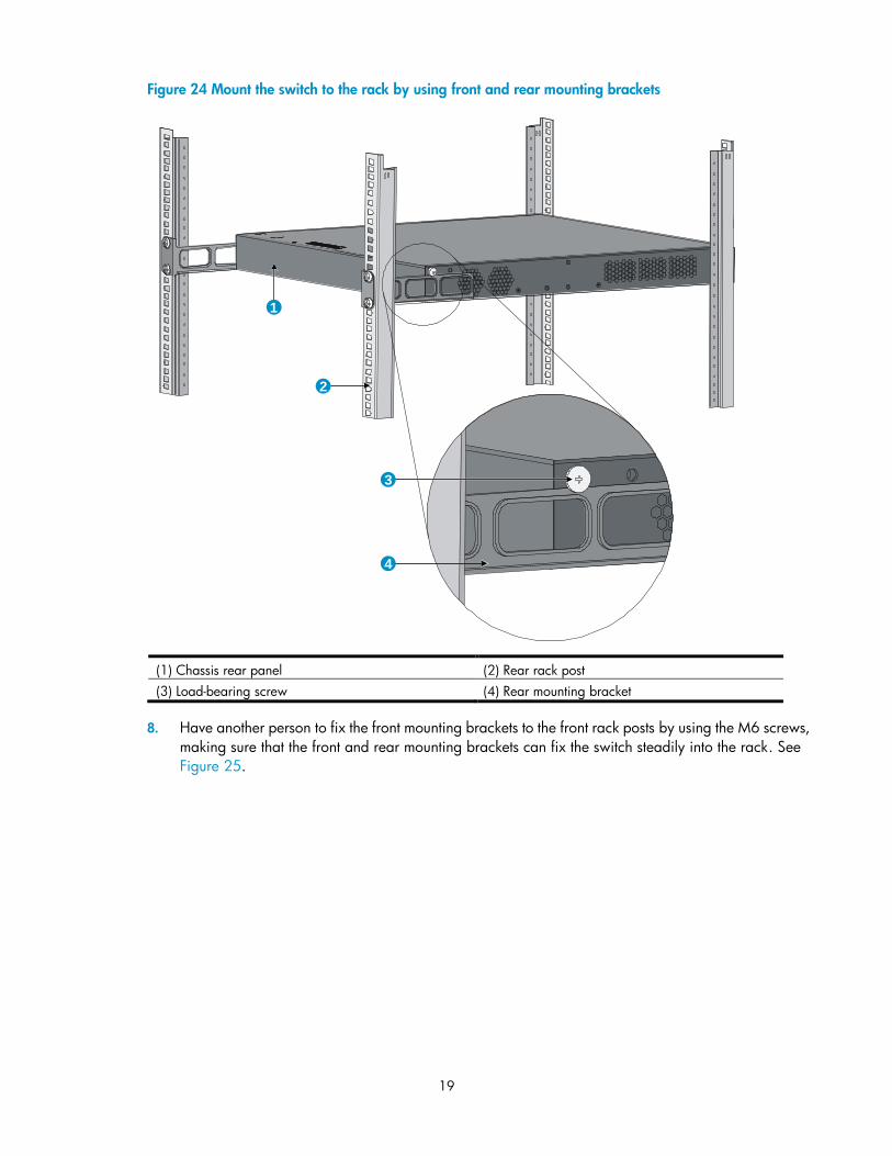
Figure 24 Mount the switch to the rack by using front and rear mounting brackets
1
2
3
4
(1) Chassis rear panel (2) Rear rack post
(3) Load-bearing screw (4) Rear mounting bracket
8. Have another person to fix the front mounting brackets to the front rack posts by using the M6 screws,
making sure that the front and rear mounting brackets can fix the switch steadily into the rack. See
Figure 25.
20
Figure 25 Mount the switch to the rack by using front and rear mounting brackets
1 2
3
4
5
6
(1) Load-bearing screw (2) Rear mounting bracket
(3) Chassis front panel (4) M6 screw for fix the front mounting bracket to the rack
(5) Front mounting bracket (6) Front rack post
Mounting the switch on a workbench To mount the switch on a workbench:
1. Check that the workbench is sturdy and well grounded.
2. Place the switch with bottom up, and clean the round holes in the chassis bottom with dry cloth.
3. Attach the rubber feet to the four round holes in the chassis bottom.
4. Place the switch with upside up on the workbench.
IMPORTANT:
Ensure good ventilation and 10 cm (3.94 in) of clearance around the chassis for heat dissipation.
Avoid placing heavy objects on the switch.
Non PoE switches are fanless. Install them in an environment with good ventilation. To stack switches one
on another, keep at least a vertical distance of 1.5 cm (0.59 in) between equipment.
21
Grounding the switch
WARNING!
Correctly connecting the switch grounding cable is crucial to lightning protection and EMI protection.
NOTE:
The power and grounding terminals in this section are for illustration only.
The power input end of the switch has a noise filter, whose central ground is directly connected to the chassis
to form the chassis ground (commonly known as PGND). You must securely connect this chassis ground to the
earth so the faradism and leakage electricity can be safely released to the earth to minimize EMI
susceptibility of the switch.
You can ground the switch in one of the following ways, depending on the grounding conditions available
at the installation site:
Grounding the switch with a grounding strip
Grounding the switch with a grounding conductor buried in the earth ground
Grounding the switch by using the AC power cord
Grounding cable The A3100 v2 Switch Series is provided with a yellow-green grounding cable. One end of the cable has an
OT terminal, and the other end is naked and soldered. See Figure 26.
Figure 26 Grounding cable
1
(1) OT terminal of the grounding cable
Grounding the switch with a grounding strip If a grounding strip is available at the installation site, connect the grounding cable to the grounding strip.
WARNING!
Connect the grounding cable to the grounding system in the equipment room. Do not connect it to a fire
main or lightning rod.
NOTE:
The grounding cable supplied with the A3100 v2 Switch Series does not have an auxiliary OT terminal.
Connecting the grounding cable to the switch
To connect the grounding cable:
1. Remove the grounding screw from the rear panel of the switch chassis.
22
2. Attach the grounding screw to the OT terminal of the grounding cable.
3. Use a screwdriver to fasten the grounding screw into the grounding screw hole.
Figure 27 Connect the grounding cable to the grounding hole of the switch
1 2 3
4
56
(1) Chassis rear panel (2) Grounding sign
(3) Grounding hole (4) OT terminal
(5) Grounding cable (6) Grounding screw
4. Remove the hex nut of a grounding post on the grounding strip.
5. Cut the grounding cable as appropriate for connecting to the grounding strip.
6. Make the connector on the grounding cable:
If you have an OT terminal, follow callout A in Figure 28 to make the connector: Peel 5 mm (0.20
in) of insulation sheath by using a wire stripper, and insert the bare metal part through the black
insulation covering into the end of the OT terminal. Secure the metal part of the cable to the OT
terminal with a crimper, cover the joint with the insulation covering, and heat the insulation covering
with a blow dryer to completely cover the metal part.
If you do not have an OT terminal, follow callout B in Figure 28 to make the connector: Peel the
insulation sheath by an appropriate length with a wire stripper, and then bend the naked metal
part.
7. Connect the connector to the grounding strip, and fasten it with the removed hex nut. See Figure 29.
Figure 28 Make the grounding cable connector
(B)(A)
23
Figure 29 Connect the grounding cable to a grounding strip
(A)
(B)
1 2
34
34
(1) Grounding post (2) Grounding strip
(3) Grounding cable (4) Hex nut
Grounding the switch with a grounding conductor buried in the
earth ground If the installation site has no grounding strips, but earth ground is available, hammer a 0.5 m (1.64 ft) or
longer angle iron or steel tube into the earth ground to serve as a grounding conductor.
The dimensions of the angle iron must be at least 50 × 50 × 5 mm (1.97 × 1.97 × 0.20 in). The steel tube
must be zinc-coated and its wall thickness must be at least 3.5 mm (0.14 in).
Weld the yellow-green grounding cable to the angel iron or steel tube and treat the joint for corrosion
protection.
Figure 30 Ground the switch by burying the grounding conductor into the earth
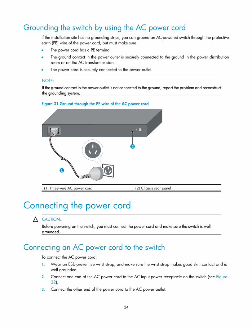
Grounding the switch by using the AC power cord If the installation site has no grounding strips, you can ground an AC-powered switch through the protective
earth (PE) wire of the power cord, but must make sure:
The power cord has a PE terminal.
The ground contact in the power outlet is securely connected to the ground in the power distribution
room or on the AC transformer side.
The power cord is securely connected to the power outlet.
NOTE:
If the ground contact in the power outlet is not connected to the ground, report the problem and reconstruct
the grounding system.
Figure 31 Ground through the PE wire of the AC power cord
1
2
(1) Three-wire AC power cord (2) Chassis rear panel
Connecting the power cord
CAUTION:
Before powering on the switch, you must connect the power cord and make sure the switch is well
grounded.
Connecting an AC power cord to the switch To connect the AC power cord:
1. Wear an ESD-preventive wrist strap, and make sure the wrist strap makes good skin contact and is
well grounded.
2. Connect one end of the AC power cord to the AC-input power receptacle on the switch (see Figure
32).
3. Connect the other end of the power cord to the AC power outlet.
25
4. Check the power LED (Power/PWR) on the front panel. If the LED is on, the power cord is properly
connected.
Figure 32 Connect the AC power cord (I)
Connecting the DC power cord The A3100-24-PoE v2 EI provides a DC power receptacle as shown in Figure 33. You can use the –48 VDC
power in the equipment room or the HP RPS DC power input.
Figure 33 DC power receptacle
+: Chassis ground —: Input voltage range (–47 VDC to –57 VDC) NULL: Reserved
To connect the DC power cord:
1. Wear an ESD-preventive wrist strap and make sure it makes good skin contact and is well grounded.
2. Unpack the DC power cord, correctly orient the plug at one end of the cable with the power receptacle
on the power supply, and insert the plug into the power receptacle (see callout 1 in Figure 34).
Figure 34 Connect the DC power cord
1
2
2
26
3. Tighten the screws on the plug with a flat-blade screwdriver to secure the plug in the power receptacle
(see callout 2 in Figure 34).
4. Connect the two wires at the other end of the power cord to a –48 VDC power source.
5. Check the power LED (PWR) on the front panel. If the LED is on, the power cord is properly connected.
CAUTION:
The length of a DC power cord must be shorter than 3 m (9.84 ft).
Verifying the installation After you complete the installation, verify that:
The grounding cable is securely connected.
The selected power supply matches that required by the switch.
The power cords are properly connected.
27
Accessing the switch for the first time
Setting up the configuration environment The first time you access the switch you must use a console cable to connect a console terminal, for example,
a PC, to the console port on the switch.
Figure 35 Connect the console port to a terminal
Connecting the console cable
Console cable A console cable is an 8-core shielded cable, with a crimped RJ-45 connector at one end for connecting to
the console port of the switch, and a DB-9 female connector at the other end for connecting to the serial port
on the console terminal.
Figure 36 Console cable
Main label
1
8B side
B
Pos.9
Pos.1
A side
A
Connection procedure To connect a terminal, for example, a PC, to the switch:
28
1. Plug the DB-9 female connector of the console cable to the serial port of the PC.
2. Connect the RJ-45 connector to the console port of the switch.
NOTE:
Identify the mark on the console port and make sure that you are connecting to the correct port.
The serial ports on PCs do not support hot swapping. If the switch has been powered on, connect the console cable
to the PC before connecting to the switch, and when you disconnect the cable, first disconnect from the switch.
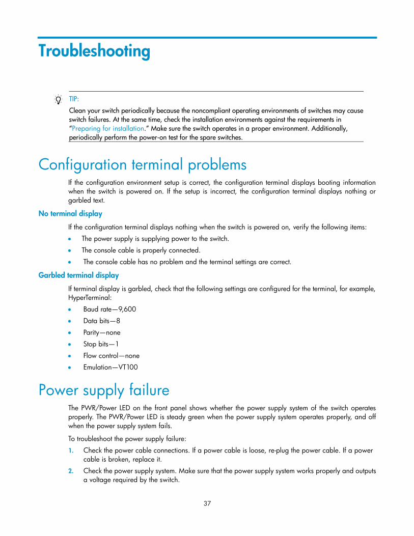
Setting terminal parameters To configure and manage the switch, you must run a terminal emulator program on the console terminal.
The following are the required terminal settings:
Bits per second—9,600
Data bits—8
Parity—None
Stop bits—1
Flow control—None
Emulation—VT100
To set terminal parameters, for example, on a Windows XP HyperTerminal: