440
HP Color LaserJet 2820/2830/2840 Service Manual
HP Color LaserJet 2820/2830/2840Service Manual


HP Color LaserJet 2820/2830/2840all-in-one
Service Manual

Copyright and License
© 2004 Copyright Hewlett-PackardDevelopment Company, LP
Reproduction, adaptation, or translationwithout prior written permission isprohibited, except as allowed under thecopyright laws.
The information contained in this documentis subject to change without notice.
The only warranties for HP products andservices are set forth in the expresswarranty statements accompanying suchproducts and services. Nothing hereinshould be construed as constituting anadditional warranty. HP shall not be liablefor technical or editorial errors or omissionscontained herein.
Part number Q3948-90943
Edition 1, 12/2004
Safety information
WARNING!
Potential Shock Hazard
Always follow basic safety precautionswhen using this product to reduce risk ofinjury from fire or electric shock.
Read and understand all instructions in thedevice user guide.
Observe all warnings and instructionsmarked on the product.
Use only a grounded electrical outlet whenconnecting the device to a power source. Ifyou do not know whether the outlet isgrounded, check with a qualified electrician.
Do not touch the contacts on the end ofany of the sockets on the device. Replacedamaged cords immediately.
Unplug this product from wall outletsbefore cleaning.
Do not install or use this product nearwater or when you are wet.
Install the product securely on a stablesurface.
Install the product in a protected locationwhere no one can step on or trip over thepower cord and where the power cord willnot be damaged.
If the product does not operate normally,see the online User Guide.
Refer all servicing questions to qualifiedpersonnel.
Information regarding FCC Class B, Parts15 and 68 requirements can be found inthe device user guide.
Trademark Credits
Adobe Photoshop and PostScript aretrademarks of Adobe Systems Incorporated.
Corel is a trademark or registeredtrademark of Corel Corporation or CorelCorporation Limited.
Microsoft, Windows, and Windows NT areU.S. registered trademarks of MicrosoftCorporation.
UNIX is a registered trademark of TheOpen Group.
ENERGY STAR® and the ENERGYSTAR® logo are U.S. registered marks ofthe United States Environmental ProtectionAgency.

Table of contents
1 Product informationChapter contents.....................................................................................................................................1Device configurations..............................................................................................................................2
HP Color LaserJet 2820 all-in-one..........................................................................................2HP Color LaserJet 2830 all-in-one..........................................................................................2HP Color LaserJet 2840 all-in-one..........................................................................................3
Device features........................................................................................................................................4Device parts.............................................................................................................................................6
Front view................................................................................................................................6Back view................................................................................................................................6Model and serial numbers......................................................................................................7
Software components............................................................................................................................12System requirements............................................................................................................12Software and supported operating systems.........................................................................12Software tips.........................................................................................................................14
Gaining access to the device features.................................................................14Obtaining the latest printing software...................................................................14Other print system software.................................................................................14
Software for Windows...........................................................................................................15Printer drivers.......................................................................................................15
Using Help...........................................................................................15Software for Macintosh.........................................................................................................15
HP Director...........................................................................................................15PPDs (Mac OS 9.2.2)...........................................................................................15PDEs (Mac OS 10.2 and 10.3)............................................................................16
HP Toolbox...........................................................................................................................16Embedded Web server (EWS).............................................................................................16Software installation..............................................................................................................16
Typical installation................................................................................................16Minimum installation.............................................................................................17
Uninstalling the printing software..........................................................................................17Using Add or Remove Programs to uninstall.......................................................17Uninstalling software for Macintosh.....................................................................18
Specifications.........................................................................................................................................19Media specifications..............................................................................................................................23
Supported media weights and sizes.....................................................................................23General guidelines................................................................................................................24Paper and print media...........................................................................................................25Special media print speeds...................................................................................................25Printing and storage environment.........................................................................................26
ENWW iii

Envelopes.............................................................................................................................27Envelope storage.................................................................................................27Envelope construction..........................................................................................27Envelopes with double side-seams......................................................................28Envelopes with adhesive strips or flaps...............................................................28
Labels....................................................................................................................................28Transparencies.....................................................................................................................29
Hewlett-Packard limited warranty statement.........................................................................................30Print Cartridge and Imaging Drum Limited Warranty Statement...........................................................31Print-cartridge information ....................................................................................................................32
Refilled print cartridges.........................................................................................................32HP LaserJet printing supplies...............................................................................................32HP Printing Supplies Returns and Recycling Program information.....................................32
Regulatory statements...........................................................................................................................33FCC Requirements (United States)......................................................................................33Telephone Consumer Protection Act (United States)..........................................................34EU statement for telecom operation.....................................................................................34New Zealand telecom statements........................................................................................34IC CS-03 requirements.........................................................................................................34Declarations of conformity....................................................................................................36
Declaration of conformity.....................................................................................36Declaration of conformity.....................................................................................36
Country-/region-specific safety statements..........................................................................38Laser safety statement.........................................................................................38Canadian DOC statement....................................................................................38Korean EMI statement.........................................................................................38Finnish laser statement........................................................................................39
2 Installation and operationChapter contents...................................................................................................................................41Operating environment .........................................................................................................................42Interface ports........................................................................................................................................43Control-panel features...........................................................................................................................44Input trays..............................................................................................................................................46Output paths..........................................................................................................................................47
Top output bin.......................................................................................................................47Rear output bin.....................................................................................................................47
Loading media.......................................................................................................................................48Loading tray 1.......................................................................................................................48Loading optional tray 2.........................................................................................................49Loading documents to scan..................................................................................................50
HP Toolbox............................................................................................................................................53Viewing HP Toolbox..............................................................................................................53Status tab..............................................................................................................................54Fax tab..................................................................................................................................54Scan to tab............................................................................................................................55Troubleshooting tab..............................................................................................................55Documentation tab................................................................................................................55Device Settings pages..........................................................................................................56
System Settings tab.............................................................................................56
iv ENWW

Print Settings tab..................................................................................................57Fax Settings tab...................................................................................................57Copy Settings tab.................................................................................................57Network Settings tab............................................................................................57
HP Toolbox links...................................................................................................................58Other links.............................................................................................................................58
Embedded Web server..........................................................................................................................59Features................................................................................................................................59
3 MaintenanceChapter contents...................................................................................................................................61Life expectancies of components..........................................................................................................62Cleaning the device...............................................................................................................................64
Cleaning the device exterior and scanner............................................................................64Cleaning the paper path.......................................................................................................65
Managing supplies.................................................................................................................................68Supplies life...........................................................................................................................68Checking and ordering supplies...........................................................................................68
To check status and order supplies using the control panel................................68To check status and order supplies using the HP Toolbox.................................69
Storing supplies....................................................................................................................69Replacing and recycling supplies.........................................................................................69HP policy for non-HP supplies..............................................................................................69
Resetting the device for non-HP supplies............................................................69HP fraud hotline....................................................................................................................70
4 Theory of operationChapter contents...................................................................................................................................71Introduction............................................................................................................................................72Engine control system...........................................................................................................................76
Basic sequence of operation................................................................................................76Power-on sequence..............................................................................................................78Motors and fans....................................................................................................................79
Laser/scanner system...........................................................................................................................80Pickup and feed system........................................................................................................................81
Optional tray 2.......................................................................................................................83Jam detection........................................................................................................................84Photosensors and switches..................................................................................................85Solenoids and clutches.........................................................................................................87Printed circuit assemblies.....................................................................................................89
Image-formation system........................................................................................................................91Image-formation process......................................................................................................93Latent-image-formation stage...............................................................................................94
Step 1: primary charging......................................................................................94Step 2: laser-beam exposure...............................................................................94
Developing stage..................................................................................................................95Step 3: auxiliary developing.................................................................................95Step 4: developing...............................................................................................95
Transfer stage.......................................................................................................................96Step 5: primary transfer........................................................................................96
ENWW v

Step 6: secondary transfer...................................................................................96Step 7: separation................................................................................................97
Fusing stage.........................................................................................................................98Step 8: fusing.......................................................................................................98Step 9: roller charging (auxiliary transfer belt cleaning roller).............................98Step 10: roller charging (transfer-belt cleaning roller).........................................99Step 11: transfer belt cleaning.............................................................................99Step 12: drum cleaning......................................................................................100
Print cartridge......................................................................................................................102Imaging-drum E-label.........................................................................................................103
Scanner and ADF functions and operation.........................................................................................104Scanner functions ..............................................................................................................104Scanner operation...............................................................................................................104ADF operation.....................................................................................................................105ADF paper path and ADF sensors.....................................................................................105ADF jam detection..............................................................................................................106
Fax functions and operation................................................................................................................107PSTN operation..................................................................................................................107To receive faxes when you hear fax tones.........................................................................107The fax subsystem..............................................................................................................107Formatter in the fax subsystem..........................................................................................108LIU in the fax subsystem....................................................................................................108
Safety isolation...................................................................................................108Safety-protection circuitry...................................................................................108Data path............................................................................................................109Hook state..........................................................................................................109Downstream current detection...........................................................................109Hook switch control............................................................................................109Ring detect.........................................................................................................110Line current control............................................................................................110Billing (metering) tone filters..............................................................................110
Fax page storage in flash memory.....................................................................................110Stored fax pages................................................................................................111Advantages of flash memory storage ...............................................................111
5 Removal and replacementChapter contents.................................................................................................................................113Removal and replacement strategy ....................................................................................................114
Required tools.....................................................................................................................114Screws................................................................................................................................114Electrostatic discharge........................................................................................................115Before performing service...................................................................................................116After performing service......................................................................................................116Post-service tests................................................................................................................116
Test 1 (print-quality test)....................................................................................116Test 2 (copy-quality test)....................................................................................117Test 3 (fax-quality test).......................................................................................117Test 4 (memory-card test)..................................................................................117
Parts removal order............................................................................................................118User-replaceable parts........................................................................................................................119
vi ENWW

Replacing the print cartridges.............................................................................................119Replacing the imaging drum...............................................................................................121Replacing the ADF..............................................................................................................123Replacing the ADF pickup-roller assembly ........................................................................124Removing the ADF separation pad....................................................................................130Replacing the ADF scanner glass......................................................................................132Replacing the fuser assembly.............................................................................................133Replacing the control-panel bezel......................................................................................134Replacing the tray 1 pickup roller and separation pad.......................................................135
Covers.................................................................................................................................................142Removing the left cover......................................................................................................142Removing the right cover....................................................................................................145Removing the right rear cover............................................................................................146Removing the scanning assembly......................................................................................148Removing the left rear cover...............................................................................................153Removing the left upper cover............................................................................................153Removing the right upper cover..........................................................................................155Replacing the memory-card assembly (HP Color LaserJet 2840 all-in-one only).............157Removing the input/output (I/O) cover................................................................................158Removing the back cover...................................................................................................161Removing the top cover assembly.....................................................................................162Removing the upper multipurpose cover............................................................................165Removing the density sensor and top-of-page sensor.......................................................167Removing the multipurpose roller cover.............................................................................168Removing the lower multipurpose cover............................................................................169
Main assemblies..................................................................................................................................172Removing the control panel................................................................................................172Removing the left support assembly..................................................................................173Removing the right support assembly................................................................................174Removing the laser/scanner assembly...............................................................................175Removing the transfer-roller plate......................................................................................177Removing the transfer roller...............................................................................................178Removing the formatter assemblies...................................................................................180
Removing the formatter cage.............................................................................180Removing the formatter and line interface unit (LIU).........................................182
Removing the E-label reader (for imaging-drum E-labels).................................................185Removing the DC controller................................................................................................187Removing the top plate.......................................................................................................189Removing the gear assembly.............................................................................................192Removing the waste-toner sensor......................................................................................195Removing the rotary-drive assembly..................................................................................196Removing the print-cartridge carousel................................................................................199Aligning the carousel gears................................................................................................203Removing the registration-roller assembly.........................................................................204Removing the toner-catch tray............................................................................................204Removing the feed-drive shaft and belts............................................................................205Removing the power supply cover plate.............................................................................214Removing the paper-top sensor.........................................................................................218Removing the fuser-wrap sensor........................................................................................219
Motors and fans...................................................................................................................................222
ENWW vii

Removing the fuser motor..................................................................................................222Removing the carousel-engagement motor.......................................................................223Removing the air duct and fan............................................................................................223
Printed circuit assemblies (PCAs).......................................................................................................225Removing the sub-high-voltage transformer PCA..............................................................225Removing the high-voltage transformer PCA.....................................................................226Removing the low-voltage PCA..........................................................................................226
Trays....................................................................................................................................................229Removing tray 1 (multipurpose tray)..................................................................................229Removing optional tray 2 (250-sheet tray).........................................................................230Removing the optional tray 2 pickup roller.........................................................................233Replacing the optional tray 2 separation pad.....................................................................235
6 TroubleshootingSupport strategy..................................................................................................................................238Troubleshooting process.....................................................................................................................239
Troubleshooting checklist...................................................................................................239Control-panel messages......................................................................................................................244
Alert and warning messages..............................................................................................244Critical error messages.......................................................................................................253
Clearing jams.......................................................................................................................................256Media jams occur in the device..........................................................................................256
Tips to avoid media jams ..................................................................................256Where to look for jams.......................................................................................256To clear a media jam inside the device.............................................................257To clear output area jams..................................................................................258
Media jams occur in the automatic document feeder (ADF)..............................................260To clear a media jam from the automatic document feeder (ADF) ..................260
Print problems......................................................................................................................................263Print quality problems.........................................................................................................263
Improving print quality........................................................................................263Understanding print-quality settings..................................................263
To temporarily change print-quality settings.....................263To change print-quality settings for all future jobs............263
Identifying and correcting print defects..............................................................263Print-quality checklist.........................................................................264General print quality issues...............................................................265Solving issues with color documents................................................271
Media-handling problems...................................................................................................272Print-media guidelines........................................................................................272Solving print-media problems............................................................................273
Performance problems.......................................................................................................274Scan problems.....................................................................................................................................276
Solving scanned image problems.......................................................................................276Scan quality problems........................................................................................................277
Preventing problems..........................................................................................277Solving scan-quality problems...........................................................................278
Scan-specific error messages............................................................................................279Copy problems.....................................................................................................................................280
Preventing problems...........................................................................................................280
viii ENWW

Image problems..................................................................................................................280Media-handling problems...................................................................................................282Performance problems.......................................................................................................283
Fax problems.......................................................................................................................................285Problems receiving faxes....................................................................................................285Problems sending faxes.....................................................................................................287Voice call problems.............................................................................................................288Media-handling problems...................................................................................................289Performance problems.......................................................................................................289
Memory card problems........................................................................................................................291Missing or wrong files.........................................................................................................291Index page not printing.......................................................................................................291Proof sheet not printing.......................................................................................................292Proof sheet not scanning....................................................................................................292Issues with photo printing...................................................................................................293
Functional tests....................................................................................................................................295Engine test..........................................................................................................................295Half self-test check..............................................................................................................296Heating element test...........................................................................................................296Cartridge high-voltage contact test.....................................................................................299Paper-path test...................................................................................................................299
Service-mode functions.......................................................................................................................301NVRAM initialization...........................................................................................................301Secondary service menu....................................................................................................301
To print secondary service reports.....................................................................303Troubleshooting tools..........................................................................................................................306
Device pages and reports...................................................................................................306Demo page.........................................................................................................306Configuration page.............................................................................................306Supplies Status page.........................................................................................306Usage page........................................................................................................306Engine-test page................................................................................................307Error log..............................................................................................................307
Fax reports..........................................................................................................................307Fax activity log...................................................................................................307Fax call report....................................................................................................307T.30 protocol trace.............................................................................................308
HP Toolbox.........................................................................................................................317To view HP Toolbox...........................................................................................317Troubleshooting tab...........................................................................................317
Service menu......................................................................................................................318Restoring the factory-set defaults......................................................................318Cleaning the paper path.....................................................................................318Setting the scanner bulb power save time.........................................................319Reducing paper curl...........................................................................................319
Service-only tools................................................................................................................320Timing charts......................................................................................................320Locations of connectors.....................................................................................322DC controller connections..................................................................................325Printer calibration...............................................................................................326
ENWW ix

Repetitive image defect ruler.............................................................................327Main wiring diagram...........................................................................................328
Updating or recovering the firmware code..........................................................................................330Firmware update by using flash executable.......................................................................330Firmware-recovery DIMM...................................................................................................330
7 Parts and diagramsChapter contents.................................................................................................................................333Ordering parts and supplies................................................................................................................334
Parts....................................................................................................................................334Related documentation and software.................................................................................334Supplies..............................................................................................................................334
Accessories.........................................................................................................................................335Accessories.........................................................................................................................335Replacement kits................................................................................................................337Automatic document feeder and scanner assembly..........................................................339Assembly locations (1 of 2).................................................................................................342Assembly locations (2 of 2).................................................................................................344
Covers.................................................................................................................................................346Internal assemblies..............................................................................................................................350Printed circuit assemblies (PCAs).......................................................................................................380Alphabetical parts list...........................................................................................................................382Numerical parts list..............................................................................................................................399
Index....................................................................................................................................................................417
x ENWW

1 Product information
Chapter contents● Device configurations
● Device features
● Device parts
● Software components
● Specifications
● Media specifications
● Hewlett-Packard limited warranty statement
● Print Cartridge and Imaging Drum Limited Warranty Statement
● Print-cartridge information
● Regulatory statements
ENWW Chapter contents 1
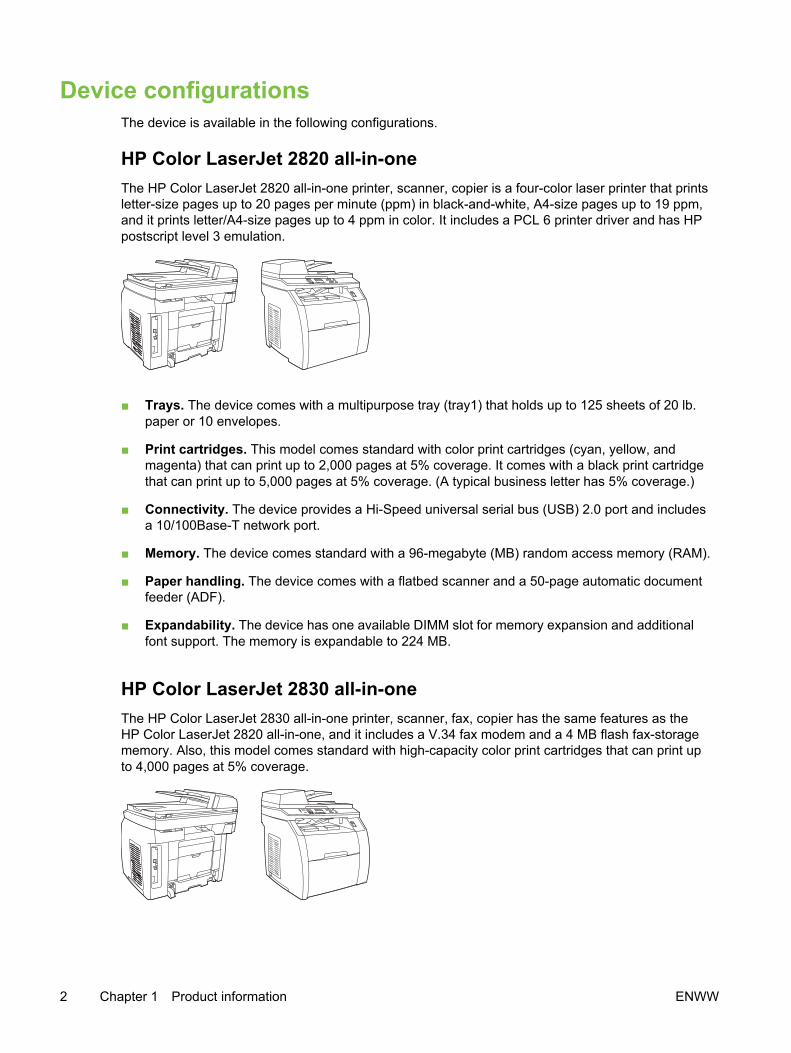
Device configurationsThe device is available in the following configurations.
HP Color LaserJet 2820 all-in-oneThe HP Color LaserJet 2820 all-in-one printer, scanner, copier is a four-color laser printer that printsletter-size pages up to 20 pages per minute (ppm) in black-and-white, A4-size pages up to 19 ppm,and it prints letter/A4-size pages up to 4 ppm in color. It includes a PCL 6 printer driver and has HPpostscript level 3 emulation.
■ Trays. The device comes with a multipurpose tray (tray1) that holds up to 125 sheets of 20 lb.paper or 10 envelopes.
■ Print cartridges. This model comes standard with color print cartridges (cyan, yellow, andmagenta) that can print up to 2,000 pages at 5% coverage. It comes with a black print cartridgethat can print up to 5,000 pages at 5% coverage. (A typical business letter has 5% coverage.)
■ Connectivity. The device provides a Hi-Speed universal serial bus (USB) 2.0 port and includesa 10/100Base-T network port.
■ Memory. The device comes standard with a 96-megabyte (MB) random access memory (RAM).
■ Paper handling. The device comes with a flatbed scanner and a 50-page automatic documentfeeder (ADF).
■ Expandability. The device has one available DIMM slot for memory expansion and additionalfont support. The memory is expandable to 224 MB.
HP Color LaserJet 2830 all-in-oneThe HP Color LaserJet 2830 all-in-one printer, scanner, fax, copier has the same features as theHP Color LaserJet 2820 all-in-one, and it includes a V.34 fax modem and a 4 MB flash fax-storagememory. Also, this model comes standard with high-capacity color print cartridges that can print upto 4,000 pages at 5% coverage.
2 Chapter 1 Product information ENWW

HP Color LaserJet 2840 all-in-oneThe HP Color LaserJet 2840 all-in-one printer, scanner, fax, copier has the same features as theHP Color LaserJet 2830 all-in-one, and also includes a 250-sheet tray (tray 2) for standard sizes.This model features rated memory-card slots as well.
ENWW Device configurations 3

Device featuresTable 1-1 HP Color LaserJet 2820/2830/2840 all-in-one features
Feature Description
Color printing ■ Provides laser printing in full color by using the four process colors: cyan,magenta, yellow, and black (CMYK).
Copy ■ Provides full-color copying from the letter/A4-sized scanner glass.
■ Includes an automatic document feeder (ADF) that allows faster, moreefficient copy jobs with multiple-page documents.
Fax ■ The HP Color LaserJet 2830/2840 all-in-one models include full-functionalityfax capabilities with a V.34 fax, including a phone book, fax polling, anddelayed-fax features.
Scan ■ Provides 1200 pixels per inch (ppi), 24-bit full-color scanning from letter/A4-sized scanner glass.
■ Includes automatic document feeder (ADF) that allows faster, more efficientscan jobs with multiple-page documents.
Fast print speed ■ Prints in black on letter-size paper up to 20ppm and on A4-size paper up to19 ppm. Prints in color on A4/letter up to 4 ppm.
Excellent print quality ■ Provides true 600 by 600 dots per inch (dpi) with Image Ret 2400 text andgraphics.
■ Offers adjustable settings to optimize print quality.
■ The HP UltraPrecise print cartridge has a finer toner formulation that providessharper text and graphics.
Printer driver features ■ Provides fast printing performance, built-in Intellifont and TrueType scalingtechnologies, and advanced imaging capabilities are benefits of the PCL 6printer language.
Automatic language-switching ■ The device automatically determines and switches to the appropriate printerlanguage (such as PostScript® or PCL 6) for the print job.
Interface connections ■ Includes a Hi-Speed USB 2.0 port (not supported for Windows NT®).
■ Includes a 10/100 ethernet (RJ45) network port.
Networking ■ Provides TCP/IP
■ LPD
■ 9100
4 Chapter 1 Product information ENWW

Feature Description
Memory card slot (HP Color LaserJet2840 all-in-one only)
The device can read the following memory-card types:
■ CompactFlash
■ Ultra CompactFlash
■ Smart Media
■ Memory Stick
■ Secure Digital
■ Multi Media Card
■ XD Card
For more information, see the device user guide.
Enhanced memory and memoryexpansion
■ The device comes with 96 MB of memory and can be expanded to 224 MBby using the DIMM slot. Most documents can be printed with the standardamount of memory with the aid of Memory Enhancement technology (MEt).MEt automatically compresses data, virtually doubling the device memoryand accommodating more complex printing with the available memory.
Energy savings ■ The device automatically conserves electricity by substantially reducingpower consumption when it is not printing.
■ As an ENERGY STAR® partner, Hewlett-Packard Company has determinedthat this product meets ENERGY STAR® guidelines for energy efficiency.ENERGY STAR® is a U.S. registered service mark of the United StatesEnvironmental Protection Agency.
Economical printing ■ N-up printing (printing more than one page on a sheet) and two-sided printingusing manual duplexing saves paper.
Supplies ■ Provides a Supplies Status page with print-cartridge and imaging-drumgauges that show the supply levels that remain. For HP supplies only.
■ Uses a no-shake cartridge design.
■ Provides authentication for HP print cartridges.
■ Offers an online supplies-ordering feature through HP Toolbox.
Accessibility ■ Includes an online user guide that is compatible with text screen-readers.
■ Provides print cartridges and an imaging drum that can be installed andremoved by using one hand.
■ All doors and covers can be opened by using one hand.
Table 1-1 HP Color LaserJet 2820/2830/2840 all-in-one features (continued)
ENWW Device features 5
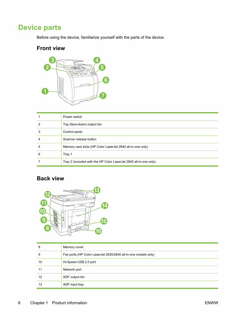
Device partsBefore using the device, familiarize yourself with the parts of the device.
Front view
1 Power switch
2 Top (face-down) output bin
3 Control panel
4 Scanner release button
5 Memory card slots (HP Color LaserJet 2840 all-in-one only)
6 Tray 1
7 Tray 2 (included with the HP Color LaserJet 2840 all-in-one only)
Back view
8 Memory cover
9 Fax ports (HP Color LaserJet 2830/2840 all-in-one models only)
10 Hi-Speed USB 2.0 port
11 Network port
12 ADF output bin
13 ADF input tray
6 Chapter 1 Product information ENWW

14 Rear (face-up) output door
15 Power connector
16 Tray 2 paper-length adjustment control
Model and serial numbersThe model number and serial number are listed on an identification label located underneath the topdoor.
The label contains information about the country/region of origin and the revision level,manufacturing date, production code, and production number of the product. The label also containspower rating and regulatory information.
Figure 1-1 HP Color LaserJet 2820/2830/2840 all-in-one identification labels (1 of 12)
Figure 1-2 HP Color LaserJet 2820/2830/2840 all-in-one identification labels (2 of 12)
ENWW Device parts 7

Figure 1-3 HP Color LaserJet 2820/2830/2840 all-in-one identification labels (3 of 12)
Figure 1-4 HP Color LaserJet 2820/2830/2840 all-in-one identification labels (4 of 12)
Figure 1-5 HP Color LaserJet 2820/2830/2840 all-in-one identification labels (5 of 12)
8 Chapter 1 Product information ENWW
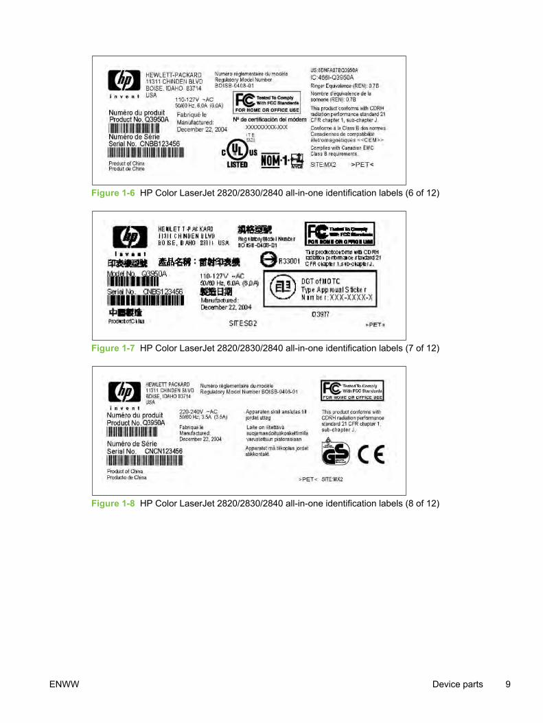
Figure 1-6 HP Color LaserJet 2820/2830/2840 all-in-one identification labels (6 of 12)
Figure 1-7 HP Color LaserJet 2820/2830/2840 all-in-one identification labels (7 of 12)
Figure 1-8 HP Color LaserJet 2820/2830/2840 all-in-one identification labels (8 of 12)
ENWW Device parts 9
Figure 1-9 HP Color LaserJet 2820/2830/2840 all-in-one identification labels (9 of 12)
Figure 1-10 HP Color LaserJet 2820/2830/2840 all-in-one identification labels (10 of 12)
Figure 1-11 HP Color LaserJet 2820/2830/2840 all-in-one identification labels (11 of 12)
10 Chapter 1 Product information ENWW

Figure 1-12 HP Color LaserJet 2820/2830/2840 all-in-one identification labels (12 of 12)
ENWW Device parts 11

Software componentsSystem requirementsTo run the device software on your computer, the computer must meet the following minimumrequirements:
Windows-based systems
■ Windows NT 4.0: Pentium II processor (Pentium III or greater recommended), 64 MB RAM, 10MB hard disk space, SVGA 800x600 16-bit color display (print driver only)
■ Windows 98 SE, Millennium Edition (Me): Pentium II processor (Pentium III or greaterrecommended), 64 MB RAM, 100 MB hard disk space, SVGA 800x600 16-bit color display,Internet Explorer v5.01 SP2 or greater (print driver, scan driver only)
■ Windows 2000, XP (32-bit home and professional versions): Pentium II processor (PentiumIII or greater recommended), 192 MB RAM, 550 MB hard disk space, SVGA 800x600 16-bit colordisplay (full install)
Mac-based systems
■ Mac OS 9.2.2: G3 or greater, 64 MB RAM, 30 MB disk space, SVGA 800x600 16-bit colordisplay (full install)
■ Mac OS X - 10.2.8 or 10.3.x: G4, G5 processor or greater, 128 MB RAM, 30 MB disk space,SVGA 800x600 16-bit color display (full install)
Software and supported operating systemsFor easy device setup and access to the full range of device features, HP strongly recommends thatthe user installs the software that is provided. Not all software is available in all languages. See thedevice getting started guide for installation instructions, and see the Readme file for the latestsoftware information.
The most recent drivers, additional drivers, and other software are available from the Internet andother sources. If the user does not have access to the Internet, see Ordering parts and supplies.
The device supports the following operating systems:
■ Microsoft Windows 98 SE, Windows 2000, Windows Me, and Windows XP (32-bit)
■ Windows NT 4.0 and Windows XP (64-bit): driver only, other device software is not available
■ Macintosh OS 9.2.2 and OS 10.2 and 10.3
■ UNIX™, Linux, and OS/2 (limited functionality)
■ Windows Server 2003 (printer driver, only from the Web)
The following tables list the software that is available for each operating system. Full softwareinstallation is available only for Windows 2000 and Windows XP systems that meet therecommended system requirements.
12 Chapter 1 Product information ENWW

Table 1-2 HP Color LaserJet 2820/2830/2840 all-in-one software
Feature Windows2000, XP1
Windows 98SE, Me
Windows NT MacintoshOS 9.2.2
MacintoshOS 10.2, 10.3
UNIX, Linux OS/2
WindowsInstaller
PCL 6 printerdriver
PS printer driver
Scanningsoftware
HP Toolboxsoftware
MacintoshInstaller
Fax software—HP ColorLaserJet2830/2840 all-in-one modelsonly
Storage driver(memory card)—HP ColorLaserJet 2840all-in-one only
DeviceConfigurationUtility
HP Director
HP Image Zone
HP DocumentViewer
MacintoshPostScriptprinterdescription(PPD) andprinter dialogextensions(PDE)
IBM drivers 2
Model scripts 3
1 The 64-bit version of Windows XP supports printer drivers only.2 Available on the HP Web site.3 Available on the HP Web site. Not specific to this device.
ENWW Software components 13

Software tipsThe following are some tips for working with the device software.
Gaining access to the device featuresThe device features are available in the printer driver. Some features such as custom paper sizesand page orientation might also be available in the program that is being used to create a file.Change settings in the program, if possible, because changes that are made in the program overridechanges that are made in the printer driver.
Gain access to advanced device features through the printer driver (or the Print dialog box forMacintosh operating systems). To open a Windows print driver, complete the following steps:
1 On the Windows taskbar, click Start, click Settings, and then click Printers.
● In Windows XP (corporate version), click Start, and then click Printers and Faxes.
A dialog box opens.
2 Right-click the printer that you want to modify, and then select Printing Preferences.
The driver opens so that you can make changes.
A number of device features and functions are also available through HP Toolbox (not available forMacintosh). For more information about HP Toolbox, see HP Toolbox.
The device CD-ROMs include the HP Scanning software. For more information about theHP Scanning software, see the software online Help.
Obtaining the latest printing softwareWhen you want to check for and install upgrades to the software, you can download drivers from theWorld Wide Web.
To download drivers
1 Go to http://www.hp.com. Click the support & drivers block.
2 Type color laserjet 2800 as the product name.
3 Select the device model that the customer has.
4 Select the correct OS and the desired software.
The Web page for the drivers might be in English, but you can download the drivers themselvesin several languages.
If the user does not have Internet access, contact HP Customer Care. See Ordering parts andsupplies or the flyer that came in the device box. See the Readme file for additional releaseinformation.
Other print system softwareThe device CD-ROMs include the HP Scanning software. See the Readme file that is provided onthe HP Color LaserJet 2820/2830/2840 all-in-one CD-ROMs for additional included software and forsupported languages.
14 Chapter 1 Product information ENWW

Software for WindowsWhen the user installs the software for Windows, the user can directly connect the device to acomputer by using a USB cable, or the user can connect the device to the network by using theinternal print server. See the device getting started guide for installation instructions, and see theReadme file for the latest software information.
The following software is available to all users of the device, whether the device was connecteddirectly to a computer by using a USB cable, or whether the device was connected to the network byusing a print server.
Printer driversA printer driver is a software component that provides access to device features and provides themeans for the computer to communicate with the device. For help using the printer driver, see UsingHelp.
Select a printer driver based on the way the customer uses the device.
■ Use the PCL 6 printer driver to take full advantage of the device features.
■ Use the PostScript (PS) printer driver for compatibility with PS needs. Certain device features arenot available in this printer driver.
The device automatically switches between HP postscript level 3 emulation and PCL printerlanguages depending on the driver selected.
Using Help
The printer driver has Help dialog boxes that can be activated from the Help button in the printerdriver, the F1 key on the computer keyboard, or the question mark symbol (?) in the upper-rightcorner of the printer driver. These Help dialog boxes give detailed information about the specificprinter driver. Help for the printer driver is separate from the Help for the software program.
Software for MacintoshFor Mac 9.2.2, the Apple LaserWriter 8 driver must be installed in order to use the PPD file. Use theApple LaserWriter 8 driver that came with the Macintosh computer. For Mac OS 10.2 and 10.3, usethe Print Center to print.
The device includes the following software for Macintosh computers.
HP DirectorHP Director is a software program that is used when working with documents. When the document isloaded into the automatic document feeder (ADF) and the computer is connected directly to thedevice, HP Director appears on the computer screen to initiate faxing or scanning, or to changesettings on the device through the Macintosh Configure Device application.
Also included is the HP all-in-one Setup Assistant, which sets up the fax and print queues.
PPDs (Mac OS 9.2.2)PostScript printer descriptions (PPDs), in combination with the LaserWriter driver, provide access tothe device features and allow the computer to communicate with the device. An installation programfor the PPDs is provided on the HP Color LaserJet 2820/2830/2840 all-in-one CD-ROM for Macintosh.
ENWW Software components 15
PDEs (Mac OS 10.2 and 10.3)Printer dialog extensions (PDEs) are code plug-ins that provide access to device features, such asinformation about the number of copies, two-sided printing, and quality settings. An installationprogram for the PDEs and other software is provided on the HP Color LaserJet 2820/2830/2840 all-in-one CD-ROM for Macintosh.
HP ToolboxYou must perform a complete software installation to use HP Toolbox.
HP Toolbox provides links to device status information and help information, such as the device userguide, and tools for diagnosing and solving problems. See HP Toolbox for more information.
NOTE For Macintosh computers, HP Toolbox is not supported.
Embedded Web server (EWS)The EWS is a Web-based interface that provides simple access to device status and deviceconfigurations, including network configurations and Smart Printing Supplies (SPS) functionality.
You can gain access to the EWS through the network connection to the device. Type the device IPaddress in a Web browser to display the device EWS homepage in the browser. From thehomepage, you can use the tabs and left navigation menu to check the status of the device,configure the device, or check the status of the supplies.
Supported browsers include:
■ Internet Explorer 5.0 or later
■ Netscape Navigator 4.75 or later
■ Opera 6.05 or later
■ Safari 1.2 or later
Software installationUse the CD-ROMs that came with the device to install the software for the proper operating system.
If your computer meets the recommended minimum requirements, you have two options wheninstalling the software.
Typical installation
NOTE This option is not available if your computer does not meet the minimumrequirements. For more information about the minimum requirements, see the box in whichthe device was packed.
16 Chapter 1 Product information ENWW

This is the recommended installation option. Select this option to install the software needed to printand scan from your computer, plus the following programs:
■ HP Toolbox: This program lets you easily monitor and set up the device settings from yourcomputer, and it offers device Help and troubleshooting. With HP Toolbox, you have desktopaccess to the device fax phone book and logs.
For more information about HP Toolbox, see HP Toolbox.
■ HP Image Zone: This program lets you view, manage, and edit images, it lets you load imagesdirectly from a camera or memory card, and it helps you share those images with others. It alsoincludes programs for scanning and for producing creative projects, such as brochures and flyers.
For more information about HP Image Zone, see the HP Image Zone online Help after you haveinstalled the software.
■ HP Document Viewer: This program lets you view and annotate PDF and TIFF files, and it letsyou export documents to other software programs. It also includes optical character recognition(OCR) software that lets you scan paper documents and convert them into electronic documentsthat can be edited.
For more information about HP Document Viewer, see the HP Document Viewer online Helpafter you have installed the software.
Minimum installationWindows 98 SE and Windows Me operating systems, as well as systems with insufficient memory(see System requirements), must perform a minimum installation to ensure that your computercontinues to operate at optimal levels.
This procedure installs the software necessary to print and scan from your computer. You will not beable to scan from the device, however. For the HP Color LaserJet 2840 all-in-one printer, scanner,fax, copier, the minimum installation also allows you to view memory cards in the device fromWindows Explorer.
Uninstalling the printing softwareUninstall software by using the following directions for your operating system.
Using Add or Remove Programs to uninstallUse the Add or Remove Programs method in Windows to remove the device software. Thismethod does not require you to have the software CD.
1 Click Start, point to Settings, and click Control Panel.
● In Windows XP, click Start, and then click Control Panel
2 Double-click Add or Remove Programs.
3 Scroll through the list of software programs and click HP Color LaserJet 2820/2830/2840 all-in-one.
4 Click Remove.
ENWW Software components 17

Uninstalling software for MacintoshTo remove the printing software from your Macintosh, open the Finder, navigate to Applications/HPLaserJet aio/HP Uninstaller, and then run the application.
18 Chapter 1 Product information ENWW

SpecificationsTable 1-3 Physical specifications
Product Height Depth Width Weight1
HP Color LaserJet2820 all-in-one andHP Color LaserJet2830 all-in-one
20.6 in (525 mm) 20.9 in (532 mm) 19.6 in (498 mm) 58.8 lbs (26.7 kg)
HP Color LaserJet2840 all-in-one withtray 2 (250-sheet)
22.6 in (573 mm) 20.9 in (532 mm) 19.6 in (498 mm) 64.5 lbs (29.3 kg)
1 Listed weight does not include print cartridges or imaging drum, which add (9.15 lbs (3.4 kg)) to the device weight.
Table 1-4 Supplies specifications
Imaging-drum life (based on 5 percent coverage) ■ 20,000 pages when printing only in black
■ 5,000 pages when printing in color
■ 6,000 to 8,000 pages is the average life
Print-cartridge life (based on 5 percent coverage) ■ Black: 5,000 pages
■ Yellow, cyan, and magenta: 2,000 pages each
■ Extended life yellow, cyan, and magenta: 4,000 pageseach
Table 1-5 Electrical specifications
Item 110-volt models 220-volt models
Power supply 110 to 127 V (+- 10%) 220 to 240 V (+- 10%)
50 / 60 Hz (+- 2Hz) 50 / 60 Hz (+- 2Hz)
Power consumption (typical)
During printing (color) 224 W (average) 217 W (average)
During printing (black and white) 400 W (average) 400 W (average)
During standby 20 W (average) 20 W (average)
Off mode 0 W (average) 0 W (average)
Heat output
Idle 64 BTU/hr 64 BTU/hr
CAUTION Power requirements are based on the country/region where the device is sold. Donot convert operating voltages. This will damage the device and void the product warranty.
ENWW Specifications 19
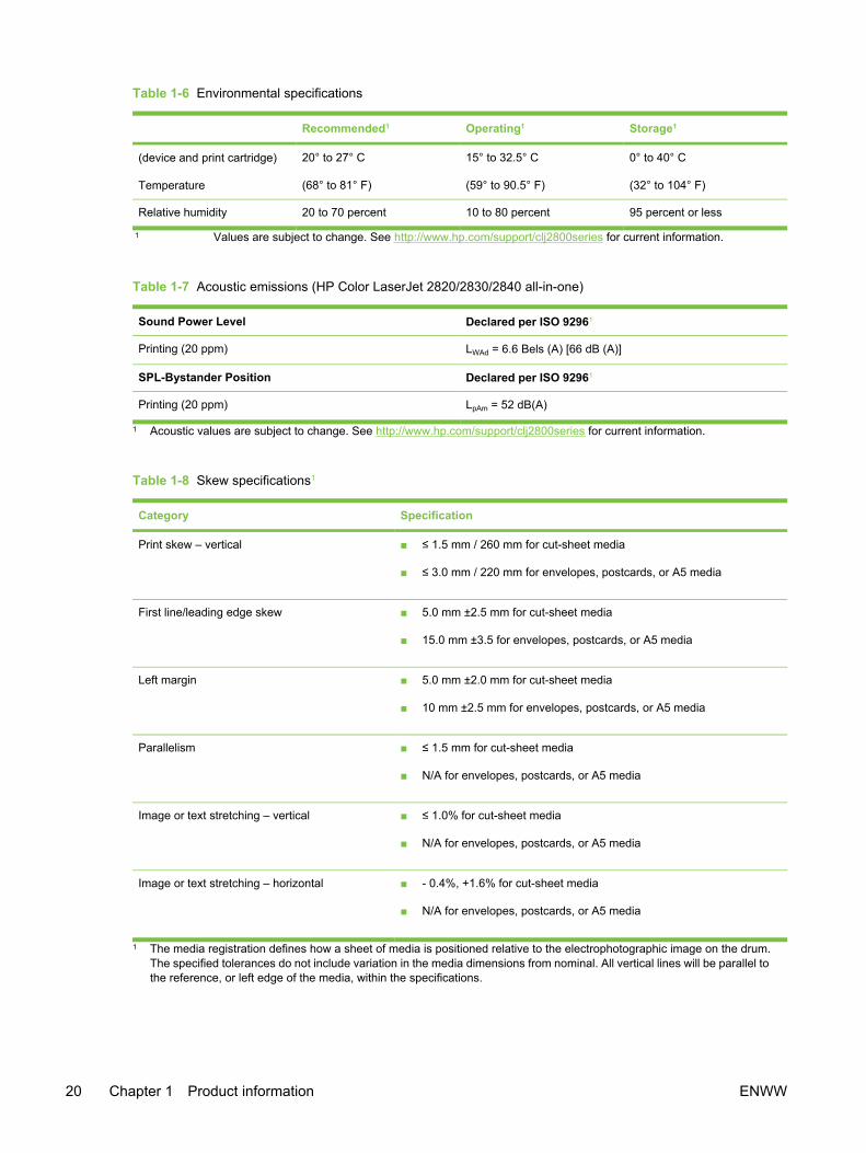
Table 1-6 Environmental specifications
Recommended1 Operating1 Storage1
(device and print cartridge)
Temperature
20° to 27° C
(68° to 81° F)
15° to 32.5° C
(59° to 90.5° F)
0° to 40° C
(32° to 104° F)
Relative humidity 20 to 70 percent 10 to 80 percent 95 percent or less
1 Values are subject to change. See http://www.hp.com/support/clj2800series for current information.
Table 1-7 Acoustic emissions (HP Color LaserJet 2820/2830/2840 all-in-one)
Sound Power Level Declared per ISO 92961
Printing (20 ppm) LWAd = 6.6 Bels (A) [66 dB (A)]
SPL-Bystander Position Declared per ISO 92961
Printing (20 ppm) LpAm = 52 dB(A)
1 Acoustic values are subject to change. See http://www.hp.com/support/clj2800series for current information.
Table 1-8 Skew specifications1
Category Specification
Print skew – vertical ■ ≤ 1.5 mm / 260 mm for cut-sheet media
■ ≤ 3.0 mm / 220 mm for envelopes, postcards, or A5 media
First line/leading edge skew ■ 5.0 mm ±2.5 mm for cut-sheet media
■ 15.0 mm ±3.5 for envelopes, postcards, or A5 media
Left margin ■ 5.0 mm ±2.0 mm for cut-sheet media
■ 10 mm ±2.5 mm for envelopes, postcards, or A5 media
Parallelism ■ ≤ 1.5 mm for cut-sheet media
■ N/A for envelopes, postcards, or A5 media
Image or text stretching – vertical ■ ≤ 1.0% for cut-sheet media
■ N/A for envelopes, postcards, or A5 media
Image or text stretching – horizontal ■ - 0.4%, +1.6% for cut-sheet media
■ N/A for envelopes, postcards, or A5 media
1 The media registration defines how a sheet of media is positioned relative to the electrophotographic image on the drum.The specified tolerances do not include variation in the media dimensions from nominal. All vertical lines will be parallel tothe reference, or left edge of the media, within the specifications.
20 Chapter 1 Product information ENWW
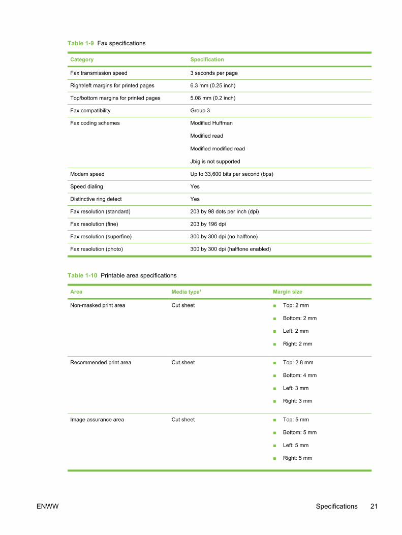
Table 1-9 Fax specifications
Category Specification
Fax transmission speed 3 seconds per page
Right/left margins for printed pages 6.3 mm (0.25 inch)
Top/bottom margins for printed pages 5.08 mm (0.2 inch)
Fax compatibility Group 3
Fax coding schemes Modified Huffman
Modified read
Modified modified read
Jbig is not supported
Modem speed Up to 33,600 bits per second (bps)
Speed dialing Yes
Distinctive ring detect Yes
Fax resolution (standard) 203 by 98 dots per inch (dpi)
Fax resolution (fine) 203 by 196 dpi
Fax resolution (superfine) 300 by 300 dpi (no halftone)
Fax resolution (photo) 300 by 300 dpi (halftone enabled)
Table 1-10 Printable area specifications
Area Media type1 Margin size
Non-masked print area Cut sheet ■ Top: 2 mm
■ Bottom: 2 mm
■ Left: 2 mm
■ Right: 2 mm
Recommended print area Cut sheet ■ Top: 2.8 mm
■ Bottom: 4 mm
■ Left: 3 mm
■ Right: 3 mm
Image assurance area Cut sheet ■ Top: 5 mm
■ Bottom: 5 mm
■ Left: 5 mm
■ Right: 5 mm
ENWW Specifications 21

Area Media type1 Margin size
Envelope ■ Top: 10 mm
■ Bottom: 10 mm
■ Left: 10 mm
■ Right: 10 mm
1 Other media types (labels, heavy media, glossy, etc.) have the same printable area as paper of the same size.
Table 1-10 Printable area specifications (continued)
22 Chapter 1 Product information ENWW

Media specificationsThis section contains information about the sizes, weights, and capacities of media that each traysupports.
Supported media weights and sizesFor optimum results, use conventional 75 to 90 g/m2 (20 to 24 lb) photocopy paper. Verify that thepaper is of good quality and is free of cuts, nicks, tears, spots, loose particles, dust, wrinkles, curls,and bent edges.
NOTE The device supports a wide range of standard and custom sizes of print media. Thecapacity of trays and bins can vary depending on media weight and thickness andenvironmental conditions. Use only transparencies that are designed for use with HP ColorLaserJet printers. Inkjet and monochrome transparencies are not supported for this device. Donot use inkjet photo media, which can melt and damage the device.
Table 1-11 Tray 1 specifications
Media Dimensions1 Weight Capacity2
Paper Minimum: 76 by 127 mm (3by 5 inches)
60 to 177 g/m2 (16 to 47 lb) Up to 125 sheets of 75 g/m2
(20 lb) paper
Maximum: 216 by 356 mm(8.5 by 14 inches)
Glossy paper Same as the precedinglisted minimum andmaximum sizes.
75 to 120 g/m2 (20 to 32 lb) Maximum stack height: 12 mm(0.47 inches)
HP Cover paper3 203 g/m2 (75 lb cover) 50 (typically)
Transparencies andopaque film
Thickness: 0.10 to 0.13 mm(3.9 to 5.1 mils)
50 (typically)
Labels4 Thickness: up to 0.23 mm(up to 9 mils)
50 (typically)
Envelopes Up to 90 g/m2 (16 to 24 lb) Up to 10
1 The device supports a wide range of standard and custom sizes of print media. Check the printer driver for supported sizes.2 Capacity can vary depending on media weight and thickness, and environmental conditions.3 Hewlett-Packard does not guarantee results when printing with other types of heavy paper.4 Smoothness: 100 to 250 (Sheffield).
Table 1-12 Optional tray 2 specifications
Media Dimensions1 Weight Capacity2
Letter 216 by 279 mm (8.5 by 11inches)
60 to 105 g/m2 (16 to 28 lb) 250 sheets of 75 g/m2 (20lb) paper
A4 210 by 297 mm (8.3 by 11.7inches)
A5 148 by 210 mm (5.8 by 8.3inches)
B5 (ISO) 176 by 250 mm (6.9 by 9.9inches)
ENWW Media specifications 23

Media Dimensions1 Weight Capacity2
B5 (JIS) 182 by 257 mm (7.2 by 10inches)
Executive 191 by 267 mm (7.3 by 10.5inches)
Legal 216 by 356 mm (8.5 by 14inches)
8.5 by 13 inches 216 by 330 mm (8.5 by 13inches)
1 The device supports a wide range of standard and custom sizes of print media. Check the printer driver for supported sizes.2 Capacity can vary depending on the media weight and thickness, and environmental conditions.
Table 1-13 Automatic document feeder (ADF) paper sizes
Media Dimensions Weight or thickness Capacity
Minimum-size paper 127 by 127 mm (5 by 5 in) 60 to 90 g/m2(16 to 24 lbbond)
50 sheets (75 g/m2; 20 lbbond)
Maximum-size paper 216 by 381 mm (8.5 by 15 in) 60 to 90 g/m2(16 to 24 lbbond)
50 sheets (75 g/m2; 20 lbbond)
NOTE Use the flatbed scanner for faxing (HP Color LaserJet 2830/2840 all-in-one modelsonly), copying, and scanning if the original is fragile, thin, thick, too small for the ADF, or aphotograph. Also use the flatbed scanner to employ the "fit to page" feature for copying. Theflatbed scanner provides the best fax, copy, and scan resolution.
General guidelinesSome media might meet all of the guidelines in this manual and still not produce satisfactory results.This problem might be the result of improper handling, unacceptable temperature and humiditylevels, or other variables over which Hewlett-Packard has no control.
Before purchasing large quantities of print media, always test a sample and make sure that the printmedia meets the requirements specified in the device user guide and in the HP LaserJet PrinterFamily Print Media Guide, which you can view on the Web at http://www.hp.com/support/ljpaperguide. For ordering information, see Ordering parts and supplies.
CAUTION Using media that does not meet HP specifications can cause problems for thedevice, requiring repair. This repair is not covered by the Hewlett-Packard warranty or serviceagreements.
This device accepts a variety of media, such as cut-sheet paper (including up to 100 percentrecycled-fiber-content paper), envelopes, labels, transparencies, glossy paper, HP LaserJet Toughpaper, and custom-size paper. Properties such as weight, composition, grain, and moisture content
Table 1-12 Optional tray 2 specifications (continued)
24 Chapter 1 Product information ENWW
are important factors affecting device performance and output quality. Media that does not meet theguidelines outlined in this manual can cause the following problems:
■ Poor print quality
■ Increased jams
■ Premature wear on the device, requiring repair
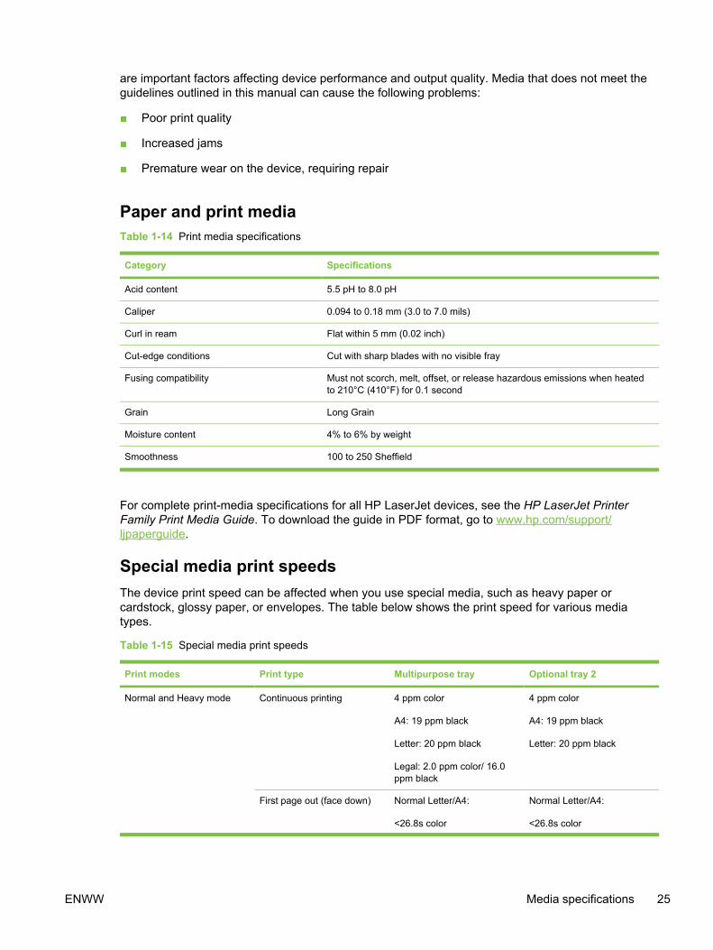
Paper and print mediaTable 1-14 Print media specifications
Category Specifications
Acid content 5.5 pH to 8.0 pH
Caliper 0.094 to 0.18 mm (3.0 to 7.0 mils)
Curl in ream Flat within 5 mm (0.02 inch)
Cut-edge conditions Cut with sharp blades with no visible fray
Fusing compatibility Must not scorch, melt, offset, or release hazardous emissions when heatedto 210°C (410°F) for 0.1 second
Grain Long Grain
Moisture content 4% to 6% by weight
Smoothness 100 to 250 Sheffield
For complete print-media specifications for all HP LaserJet devices, see the HP LaserJet PrinterFamily Print Media Guide. To download the guide in PDF format, go to www.hp.com/support/ljpaperguide.
Special media print speedsThe device print speed can be affected when you use special media, such as heavy paper orcardstock, glossy paper, or envelopes. The table below shows the print speed for various mediatypes.
Table 1-15 Special media print speeds
Print modes Print type Multipurpose tray Optional tray 2
Normal and Heavy mode Continuous printing 4 ppm color
A4: 19 ppm black
Letter: 20 ppm black
Legal: 2.0 ppm color/ 16.0ppm black
4 ppm color
A4: 19 ppm black
Letter: 20 ppm black
First page out (face down) Normal Letter/A4:
<26.8s color
Normal Letter/A4:
<26.8s color
ENWW Media specifications 25

Print modes Print type Multipurpose tray Optional tray 2
<17.6s black
Heavy Letter/A4:
<32.8s color
<23.6s black
<17.6s black
Heavy Letter/A4:
<32.8s color
<23.6s black
Heavy and Glossy mode(more than 105g/m2, 1/2speed)
Continuous printing Letter/A4:
2.45 ppm color
3.99 ppm black
N/A
First page out (face down) Letter/A4:
<31.6s color
<21.3s black
N/A
Heavy Glossy and GlossyFilm mode (1/4 speed)
Continuous printing Letter/A4:
2.0 ppm color
N/A black
N/A
First page out (face down) Letter/A4:
39.8s color
N/A black
N/A
Envelope Continuous printing 2.57 ppm color
4.48 ppm black
N/A
First page out (face down) <30.1s color
<19.8s black
N/A
Printing and storage environmentIdeally, the printing and media-storage environment should be at or near room temperature, and nottoo dry or too humid. Remember that paper is hygroscopic; it absorbs and loses moisture rapidly.
Heat works with humidity to damage paper. Heat causes the moisture in paper to evaporate, whilecold causes it to condense on the sheets. Heating systems and air conditioners remove most of thehumidity from a room. As paper is opened and used, it loses moisture, causing streaks andsmudging. Humid weather or water coolers can cause the humidity to increase in a room. As paper isopened and used it absorbs any excess moisture, causing light print and dropouts. Also, as paperloses and gains moisture it can distort. This issue can cause jams.
As a result, paper storage and handling are as important as the paper-making process itself. Paperstorage environmental conditions directly affect the feed operation and print quality.
Care should be taken not to purchase more paper than can be easily used in a short time (aboutthree months). Paper stored for long periods can experience heat and moisture extremes, which cancause damage. Planning is important to prevent damage to a large supply of paper.
Table 1-15 Special media print speeds (continued)
26 Chapter 1 Product information ENWW

Unopened paper in sealed reams can remain stable for several months before use. Openedpackages of paper have more potential for environmental damage, especially if they are not wrappedwith a moisture-proof barrier.
The media-storage environment should be properly maintained to ensure optimum deviceperformance. The required condition is 20° to 24°C (68° to 75°F), with a relative humidity of 45% to55%. The following guidelines should be helpful when evaluating the storage environment:
■ Print media should be stored at or near room temperature.
■ The air should not be too dry or too humid (to moderate the hygroscopic properties of paper).
■ The best way to store an opened ream of paper is to rewrap it tightly in its moisture-proofwrapping. If the device environment is subject to extremes, unwrap only the amount of paper tobe used to prevent unwanted moisture changes.
■ Avoid storing paper and print media near heating and air conditioning vents or near windows anddoors that are frequently open.
EnvelopesUse only tray 1 to print on envelopes. Select the type of envelope that you are using from the Printdialog box or the printer driver.
In your program, set the margins for the envelope. The following table gives typical address marginsfor a commercial #10 or DL envelope.
Table 1-16 Envelope margin specifications
Type of address Top margin Left margin
Return address 15 mm (0.6 inch) 15 mm (0.6 inch)
Delivery address 51 mm (2 inches) 89 mm (3.5 inches)
■ For the best print quality, position margins no closer than 15 mm (0.6 inch) from the edges of theenvelope.
■ Avoid printing over the area where the envelope seams meet.
Envelope storageProper storage of envelopes helps contribute to print quality. Envelopes should be stored flat. If air istrapped in an envelope and creates an air bubble, then the envelope might wrinkle during printing.
Envelope constructionEnvelope construction is critical. Envelope fold lines can vary considerably, not only betweenmanufacturers, but also within a box from the same manufacturer. Successful printing on envelopes
ENWW Media specifications 27
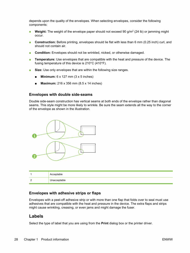
depends upon the quality of the envelopes. When selecting envelopes, consider the followingcomponents:
■ Weight: The weight of the envelope paper should not exceed 90 g/m2 (24 lb) or jamming mightoccur.
■ Construction: Before printing, envelopes should lie flat with less than 6 mm (0.25 inch) curl, andshould not contain air.
■ Condition: Envelopes should not be wrinkled, nicked, or otherwise damaged.
■ Temperature: Use envelopes that are compatible with the heat and pressure of the device. Thefusing temperature of this device is 210°C (410°F).
■ Size: Use only envelopes that are within the following size ranges.
■ Minimum: 6 x 127 mm (3 x 5 inches)
■ Maximum: 216 x 356 mm (8.5 x 14 inches)
Envelopes with double side-seamsDouble side-seam construction has vertical seams at both ends of the envelope rather than diagonalseams. This style might be more likely to wrinkle. Be sure the seam extends all the way to the cornerof the envelope as shown in the illustration.
1
2
1 Acceptable
2 Unacceptable
Envelopes with adhesive strips or flapsEnvelopes with a peel-off adhesive strip or with more than one flap that folds over to seal must useadhesives that are compatible with the heat and pressure in the device. The extra flaps and stripsmight cause wrinkling, creasing, or even jams and might damage the fuser.
LabelsSelect the type of label that you are using from the Print dialog box or the printer driver.
28 Chapter 1 Product information ENWW

CAUTION To avoid damaging the device, use only labels that are recommended for laserprinters. To prevent serious jams, always use tray 1 to print on labels and always use thestraight-through paper path. Never print on the same sheet of labels more than once or printon a partial sheet of labels.
When selecting labels, consider the quality of each component:
■ Adhesives: The adhesive material should be stable at 210°C (410°F), which is the device fusingtemperature.
■ Arrangement: Only use labels with no exposed backing between them. Labels can peel offsheets with spaces between the labels, causing serious jams.
■ Curl: Before printing, labels must lie flat with no more than 13 mm (0.5 inch) of curl in anydirection.
■ Condition: Do not use labels that have wrinkles, bubbles, or other indications of separation.
TransparenciesUse only tray 1 to print on transparencies. Select Transparencies from the Print dialog box or theprinter driver.
The device supports printing in color on transparencies. Transparencies that are used in the devicemust be able to withstand 210°C (410°F), which is the device fusing temperature.
CAUTION To avoid damage to the device, use only transparencies that are recommendedfor use in laser printers.
ENWW Media specifications 29

Hewlett-Packard limited warranty statementHP PRODUCT DURATION OF LIMITED WARRANTY
HP Color LaserJet 2820/2830/2840 all-in-one One year limited warranty
HP warrants to you, the end-user customer, that HP hardware and accessories will be free fromdefects in materials and workmanship after the date of purchase, for the period specified above. IfHP receives notice of such defects during the warranty period, HP will, at its option, either repair orreplace products which prove to be defective. Replacement products may be either new orequivalent in performance to new.
HP warrants to you that HP software will not fail to execute its programming instructions after thedate of purchase, for the period specified above, due to defects in material and workmanship whenproperly installed and used. If HP receives notice of such defects during the warranty period, HP willreplace software which does not execute its programming instructions due to such defects.
HP does not warrant that the operation of HP products will be uninterrupted or error free. If HP isunable, within a reasonable time, to repair or replace any product to a condition as warranted, youwill be entitled to a refund of the purchase price upon prompt return of the product.
HP products may contain remanufactured parts equivalent to new in performance or may have beensubject to incidental use.
Warranty does not apply to defects resulting from (a) improper or inadequate maintenance orcalibration, (b) software, interfacing, parts or supplies not supplied by HP, (c) unauthorizedmodification or misuse, (d) operation outside of the published environmental specifications for theproduct, or (e) improper site preparation or maintenance.
TO THE EXTENT ALLOWED BY LOCAL LAW, THE ABOVE WARRANTIES ARE EXCLUSIVE ANDNO OTHER WARRANTY OR CONDITION, WHETHER WRITTEN OR ORAL, IS EXPRESSED ORIMPLIED AND HP SPECIFICALLY DISCLAIMS ANY IMPLIED WARRANTIES OR CONDITIONS OFMERCHANTABILITY, SATISFACTORY QUALITY, AND FITNESS FOR A PARTICULARPURPOSE. Some countries/regions, states or provinces do not allow limitations on the duration of animplied warranty, so the above limitation or exclusion might not apply to you. This warranty gives youspecific legal rights and you might also have other rights that vary from country/region to country/region, state to state, or province to province.
HP's limited warranty is valid in any country/region or locality where HP has a support presence forthis product and where HP has marketed this product. The level of warranty service you receive mayvary according to local standards. HP will not alter form, fit or function of the product to make itoperate in a country/region for which it was never intended to function for legal or regulatory reasons.
TO THE EXTENT ALLOWED BY LOCAL LAW, THE REMEDIES IN THIS WARRANTYSTATEMENT ARE YOUR SOLE AND EXCLUSIVE REMEDIES. EXCEPT AS INDICATED ABOVE,IN NO EVENT WILL HP OR ITS SUPPLIERS BE LIABLE FOR LOSS OF DATA OR FOR DIRECT,SPECIAL, INCIDENTAL, CONSEQUENTIAL (INCLUDING LOST PROFIT OR DATA), OR OTHERDAMAGE, WHETHER BASED IN CONTRACT, TORT, OR OTHERWISE. Some countries/regions,states or provinces do not allow the exclusion or limitation of incidental or consequential damages,so the above limitation or exclusion may not apply to you.
THE WARRANTY TERMS CONTAINED IN THIS STATEMENT, EXCEPT TO THE EXTENTLAWFULLY PERMITTED, DO NOT EXCLUDE, RESTRICT OR MODIFY AND ARE IN ADDITIONTO THE MANDATORY STATUTORY RIGHTS APPLICABLE TO THE SALE OF THIS PRODUCTTO YOU.
30 Chapter 1 Product information ENWW

Print Cartridge and Imaging Drum Limited WarrantyStatement
This HP product is warranted to be free from defects in materials and workmanship.
This warranty does not apply to products that (a) have been refilled, refurbished, remanufactured, ortampered with in any way, (b) experience problems resulting from misuse, improper storage, oroperation outside of the published environmental specifications for the printer product, or (c) exhibitwear from ordinary use.
To obtain warranty service, please return the product to place of purchase (with a written descriptionof the problem and print samples) or contact HP customer support. At HP's option, HP will eitherreplace products that prove to be defective or refund your purchase price.
TO THE EXTENT ALLOWED BY LOCAL LAW, THE ABOVE WARRANTY IS EXCLUSIVE AND NOOTHER WARRANTY OR CONDITION, WHETHER WRITTEN OR ORAL, IS EXPRESSED ORIMPLIED AND HP SPECIFICALLY DISCLAIMS ANY IMPLIED WARRANTIES OR CONDITIONS OFMERCHANTABILITY, SATISFACTORY QUALITY, AND FITNESS FOR A PARTICULAR PURPOSE.
TO THE EXTENT ALLOWED BY LOCAL LAW, IN NO EVENT WILL HP OR ITS SUPPLIERS BELIABLE FOR DIRECT, SPECIAL, INCIDENTAL, CONSEQUENTIAL (INCLUDING LOST PROFITOR DATA), OR OTHER DAMAGE, WHETHER BASED IN CONTRACT, TORT, OR OTHERWISE.
THE WARRANTY TERMS CONTAINED IN THIS STATEMENT, EXCEPT TO THE EXTENTLAWFULLY PERMITTED, DO NOT EXCLUDE, RESTRICT OR MODIFY AND ARE IN ADDITIONTO THE MANDATORY STATUTORY RIGHTS APPLICABLE TO THE SALE OF THIS PRODUCTTO YOU.
ENWW Print Cartridge and Imaging Drum Limited Warranty Statement 31
Print-cartridge information At 5% page coverage, a black print cartridge will print approximately 5,000 pages. Color printcartridges (yellow, cyan, and magenta) will print 2,000 pages each, and high-capacity color printcartridges (yellow, cyan, and magenta) will print 4,000 pages each. These estimates are onlyapproximate; usage conditions and print patterns can cause results to vary.
Refilled print cartridgesWhile HP does not prohibit the use of refilled print cartridges during the warranty period or while theproduct is under a maintenance contract, it is not recommended for the following reasons:
■ Repairs resulting from the use of refilled cartridges are not covered under HP warranty ormaintenance contracts.
■ HP has no controls or processes to ensure that a refilled cartridge functions at the high level ofreliability of a new HP LaserJet print cartridge. HP also cannot predict the long-term reliabilityeffect on the product from using different toner formulations found in refilled cartridges.
■ The print quality of HP LaserJet print cartridges influences the customer’s perception of theproduct. HP has no control over the actual print quality of a refilled cartridge.
■ Parts that are critical to print quality might not be replaced when the cartridge is refilled with toner.
HP LaserJet printing suppliesIn many countries/regions, this product's printing supplies (for example the print cartridge) can bereturned to HP through the HP Printing Supplies Returns and Recycling Program. An easy-to-useand free take-back program is available in more than 30 countries/regions. Multilingual programinformation and instructions are included in every new HP LaserJet print cartridge and suppliespackage.
HP Printing Supplies Returns and Recycling Program informationSince 1990, the HP Printing Supplies Returns and Recycling Program has collected millions of usedLaserJet print cartridges that otherwise might have been discarded in the world's landfills. TheHP LaserJet print cartridges and supplies are collected and bulk shipped to our resource andrecovery partners, who disassemble the cartridges. Remaining materials are separated andconverted into raw materials for use by other industries to make a variety of useful products.
U.S. returns
For a more environmentally responsible return of used cartridges and supplies, HP encourages theuse of bulk returns. Simply bundle two or more cartridges together and use the single, pre-paid, pre-addressed UPS label that is supplied in the package that the new cartridge comes in. For moreinformation in the U.S., call 800-340-2445 or visit the HP LaserJet Supplies Web site at www.hp.com/recycle.
Non-U.S. returns
Non-U.S. customers should call the local HP Sales and Service office or visit the www.hp.com/recycle Web site for further information regarding availability of the HP Supplies Returns andRecycling program.
32 Chapter 1 Product information ENWW

Regulatory statementsFCC Requirements (United States)This equipment has been tested and found to comply with the limits for a Class B digital device,pursuant to Part 15 of the FCC rules. These limits are designed to provide reasonable protectionagainst harmful interference in a residential installation. This equipment generates, uses, and canradiate radio frequency energy. If not installed and used in accordance with the instructions, it maycause harmful interference to radio communications. However, there is no guarantee thatinterference will not occur in a particular installation. If this equipment does cause harmfulinterference to radio or television reception, which can be determined by turning the equipment offand on, the user is encouraged to try to correct the interference by one or more of the followingmeasures:
Reorient or relocate the receiving antenna.
Increase separation between equipment and receiver.
Connect equipment to an outlet on a circuit different from that to which the receiver is located.
Consult your dealer or an experienced radio/TV technician.
Any changes or modifications to the printer that are not expressly approved by HP could void theuser's authority to operate this equipment.
Use of a shielded interface cable is required to comply with the Class B limits of Part 15 of FCC rules.
This equipment complies with FCC rules, Part 68. On the back of this equipment is a label thatcontains, among other information, the FCC registration number and ringer equivalence number(REN) for this equipment. If requested, this information must be provided to the telephone company.The REN is used to determine the quantity of devices which may be connected to the telephone line.Excessive RENs on the telephone line may result in the devices not ringing in response to anincoming call. In most, but not all, areas, the sum of the RENs should not exceed five (5.0). To becertain of the number of devices that may be connected to the line, as determined by the total RENs,contact the telephone company to determine the maximum REN for the calling area.
This equipment uses the following USOC jacks: RJ11C.
An FCC-compliant telephone cord and modular plug is provided with this equipment. This equipmentis designed to be connected to the telephone network or premises wiring using a compatible modularjack which is Part 68 compliant. This equipment cannot be used on telephone company-providedcoin service. Connection to Party Line Service is subject to state tariffs. If this equipment causesharm to the telephone network, the telephone company will notify you in advance that temporarydiscontinuance of service may be required. If advance notice is not practical, the telephone companywill notify the customer as soon as possible. Also, you will be advised of your right to file a complaintwith the FCC if you believe it is necessary. The telephone company may make changes in itsfacilities, equipment, operations, or procedures that could affect the operation of the equipment. Ifthis happens, the telephone company will provide advance notice in order for you to make thenecessary modifications in order to maintain uninterrupted service. If trouble is experienced with thisequipment, please see the numbers in the front of this manual for repair and (or) warrantyinformation. If the trouble is causing harm to the telephone network, the telephone company mayrequest you remove the equipment from the network until the problem is resolved. The followingrepairs can be done by the customer: Replace any original equipment that came with the device.This includes the print cartridge, the supports for trays and bins, the power cord, and the telephonecord. It is recommended that the customer install an AC surge arrestor in the AC outlet to which this
ENWW Regulatory statements 33

device is connected. This is to avoid damage to the equipment caused by local lightning strikes andother electrical surges.
Telephone Consumer Protection Act (United States)The Telephone Consumer Protection Act of 1991 makes it unlawful for any person to use a computeror other electronic device, including fax machines, to send any message unless such messageclearly contains, in a margin at the top or bottom of each transmitted page or on the first page of thetransmission, the date and time it is sent and an identification of the business, other entity, orindividual sending the message and the telephone number of the sending machine or such business,other entity, or individual. (The telephone number provided cannot be a 900 number or any othernumber for which charges exceed local or long-distance transmission charges.) In order to programthis information into your facsimile, see the device user guide.
EU statement for telecom operationThis product is intended to be connected to the analog Public Switched TelecommunicationNetworks (PSTN) of European Economic Area (EEA) countries/regions. It meets requirements of EUR&TTE Directive 1999/5/EC (Annex II) and carries appropriate CE conformity marking. For moredetails, see Declaration of Conformity issued by the manufacturer in another section of this manual.However, due to differences between individual national PSTNs, the product may not guaranteeunconditional assurance of successful operation on every PSTN termination point. Networkcompatibility depends on the correct setting being selected by the customer in preparation of itsconnection to the PSTN. Please follow the instructions provided in the user manual. If youexperience network compatibility issues, please contact your equipment supplier or Hewlett-Packardhelp desk in the country/region of operation. Connecting to a PSTN termination point may be thesubject of additional requirements set out by the local PSTN operator.
New Zealand telecom statementsThe grant of a Telepermit for any item of terminal equipment indicates only that Telecom hasaccepted that the item complies with minimum conditions for connection to its network. It indicates noendorsement of the product by Telecom, nor does it provide any sort of warranty. Above all, itprovides no assurance that any item will work correctly in all respects with another item ofTelepermitted equipment of a different make or model, nor does it imply that any product iscompatible with all of Telecom's network services.
This equipment may not provide for the effective hand-over of a call to another device connected tothe same line.
This equipment shall not be set up to make automatic calls to the Telecom “111” Emergency Service.
IC CS-03 requirementsNotice: The Industry Canada label identifies certified equipment. This certification means theequipment meets certain telecommunications network protective, operational, and safetyrequirements as prescribed in the appropriate Terminal Equipment Technical Requirement document(s). The Department does not guarantee the equipment will operate to the user's satisfaction. Beforeinstalling this equipment, users should ensure that it is permissible for the equipment to beconnected to the facilities of the local telecommunications company. The equipment must also beinstalled using an acceptable method of connection. The customer should be aware that compliancewith the above conditions may not prevent degradation of service in some situations. Repairs tocertified equipment should be coordinated by a representative designated by the supplier. Anyrepairs or alterations made by the user to this equipment, or equipment malfunctions, may give thetelecommunications company cause to request the user to disconnect the equipment. Users should
34 Chapter 1 Product information ENWW

ensure for their own protection that the electrical ground connections of the power utility, telephonelines, and internal metallic water pipe system, if present, are connected together. This precaution canbe particularly important in rural areas.
CAUTION Users should not attempt to make such connections themselves, but shouldcontact the appropriate electric inspection authority, or electrician, as appropriate. The RingerEquivalence Number (REN) of this device is 0.7.
Notice: The Ringer Equivalence Number (REN) assigned to each terminal device provides anindication of the maximum number of terminals allowed to be connected to a telephone interface.The termination on an interface may consist of any combination of devices subject only to therequirement that the sum of the Ringer Equivalence Number of all the devices does not exceed five(5.0). The standard connecting arrangement code (telephone jack type) for equipment with directconnections to the telephone network is CA11A.
ENWW Regulatory statements 35
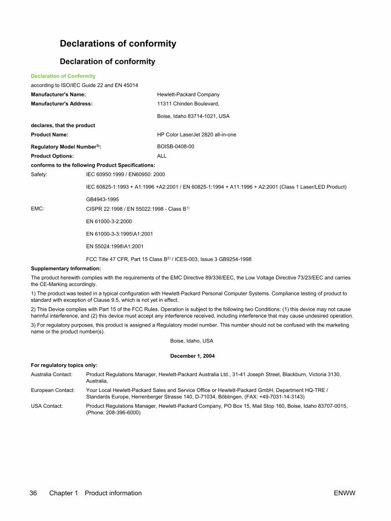
Declarations of conformity
Declaration of conformity
Declaration of Conformity
according to ISO/IEC Guide 22 and EN 45014
Manufacturer's Name: Hewlett-Packard Company
Manufacturer's Address: 11311 Chinden Boulevard,
Boise, Idaho 83714-1021, USA
declares, that the product
Product Name: HP Color LaserJet 2820 all-in-one
Regulatory Model Number3): BOISB-0408-00
Product Options: ALL
conforms to the following Product Specifications:
Safety: IEC 60950:1999 / EN60950: 2000
IEC 60825-1:1993 + A1:1996 +A2:2001 / EN 60825-1:1994 + A11:1996 + A2:2001 (Class 1 Laser/LED Product)
GB4943-1995
EMC: CISPR 22:1998 / EN 55022:1998 - Class B1)
EN 61000-3-2:2000
EN 61000-3-3:1995\A1:2001
EN 55024:1998\A1:2001
FCC Title 47 CFR, Part 15 Class B2) / ICES-003, Issue 3 GB9254-1998
Supplementary Information:
The product herewith complies with the requirements of the EMC Directive 89/336/EEC, the Low Voltage Directive 73/23/EEC and carriesthe CE-Marking accordingly.
1) The product was tested in a typical configuration with Hewlett-Packard Personal Computer Systems. Compliance testing of product tostandard with exception of Clause 9.5, which is not yet in effect.
2) This Device complies with Part 15 of the FCC Rules. Operation is subject to the following two Conditions: (1) this device may not causeharmful interference, and (2) this device must accept any interference received, including interference that may cause undesired operation.
3) For regulatory purposes, this product is assigned a Regulatory model number. This number should not be confused with the marketingname or the product number(s).
Boise, Idaho, USA
December 1, 2004
For regulatory topics only:
Australia Contact: Product Regulations Manager, Hewlett-Packard Australia Ltd., 31-41 Joseph Street, Blackburn, Victoria 3130,Australia,
European Contact: Your Local Hewlett-Packard Sales and Service Office or Hewlett-Packard GmbH, Department HQ-TRE /Standards Europe, Herrenberger Strasse 140, D-71034, Böblingen, (FAX: +49-7031-14-3143)
USA Contact: Product Regulations Manager, Hewlett-Packard Company, PO Box 15, Mail Stop 160, Boise, Idaho 83707-0015,(Phone: 208-396-6000)
36 Chapter 1 Product information ENWW

Manufacturer's Name: Hewlett-Packard Company
Manufacturer's Address: 11311 Chinden Boulevard,
Boise, Idaho 83714-1021, USA
declares, that the product
Product Name: HP Color LaserJet 2830 and 2840 all-in-one
Regulatory Model Number3): BOISB0408-01
Product Options: ALL
conforms to the following Product Specifications:
Safety: IEC 60950:1999 / EN60950: 2000
IEC 60825-1:1993 + A1:1996 +A2:2001 / EN 60825-1:1994 + A11:1996 + A2:2001 (Class 1 Laser/LED Product)
GB4943-1995
EMC: CISPR 22:1998 / EN 55022:1998 - Class B1)
EN 61000-3-2:2000
EN 61000-3-3:1995\A1:2001
EN 55024:1998\A1:2001
FCC Title 47 CFR, Part 15 Class B2) / ICES-003, Issue 3 GB9254-1998
TELECOM: TBR-21:1998; EG 201 121:1998
Supplementary Information:
The product herewith complies with the requirements of the EMC Directive 89/336/EEC, the Low Voltage Directive 73/23/EEC, the R&TTEDirective 1999/5/EC (Annex II) and carries the CE-Marking accordingly.
1) The product was tested in a typical configuration with Hewlett-Packard Personal Computer Systems. Compliance testing of product tostandard with exception of Clause 9.5, which is not yet in effect.
2) This Device complies with Part 15 of the FCC Rules. Operation is subject to the following two Conditions: (1) this device may not causeharmful interference, and (2) this device must accept any interference received, including interference that may cause undesired operation.
3) For regulatory purposes, this product is assigned a Regulatory model number. This number should not be confused with the marketingname or the product number(s).
Boise, Idaho, USA
December 1, 2004
For regulatory topics only:
Australia Contact: Product Regulations Manager, Hewlett-Packard Australia Ltd.,, 31-41 Joseph Street, Blackburn, Victoria 3130,Australia,
European Contact: Your Local Hewlett-Packard Sales and Service Office or Hewlett-Packard GmbH, Department HQ-TRE /Standards Europe, Herrenberger Strasse 140, D-71034, Böblingen, (FAX: +49-7031-14-3143)
USA Contact: Product Regulations Manager, Hewlett-Packard Company, PO Box 15, Mail Stop 160, Boise, Idaho 83707-0015,(Phone: 208-396-6000)
ENWW Regulatory statements 37
Declaration of conformityDeclaration of Conformity
according to ISO/IEC Guide 22 and EN 45014

Country-/region-specific safety statements
Laser safety statementThe Center for Devices and Radiological Health (CDRH) of the U.S. Food and Drug Administrationhas implemented regulations for laser products manufactured since August 1, 1976. Compliance ismandatory for products marketed in the United States. The printer is certified as a "Class 1" laserproduct under the U.S. Department of Health and Human Services (DHHS) Radiation PerformanceStandard according to the Radiation Control for Health and Safety Act of 1968.
Since radiation emitted inside the printer is completely confined within protective housings andexternal covers, the laser beam cannot escape during any phase of normal user operation.
WARNING! Using controls, making adjustments, or performing procedures other than thosespecified in the device user guide may result in exposure to hazardous radiation.
Canadian DOC statementComplies with Canadian EMC Class B requirements.
«Conforme àla classe B des normes canadiennes de compatibilité électromagnétiques (CEM).»
Korean EMI statement
38 Chapter 1 Product information ENWW

Finnish laser statementLASERTURVALLISUUS
LUOKAN 1 LASERLAITE
KLASS 1 LASER APPARAT
HP Color LaserJet 2820/2830/2840 -laserkirjoitin on käyttäjän kannalta turvallinen luokan1 laserlaite. Normaalissa käytössä kirjoittimen suojakotelointi estää lasersäteen pääsynlaitteen ulkopuolelle.
Laitteen turvallisuusluokka on määritetty standardin EN60825-1 (1994) mukaisesti.
VAROITUS!
Laitteen käyttäminen muulla kuin käyttöohjeessa mainitulla tavalla saattaa altistaakäyttäjän turvallisuusluokan 1 ylittävälle näkymättömälle lasersäteilylle.
VARNING!
Om apparaten används på annat sätt än i bruksanvisning specificerats, kan användarenutsättas för osynlig laserstrålning, som överskrider gränsen för laserklass 1.
HUOLTO
HP Color LaserJet 2820/2830/2840 -kirjoittimen sisällä ei ole käyttäjän huollettavissaolevia kohteita. Laitteen saa avata ja huoltaa ainoastaan sen huoltamiseen koulutettuhenkilö. Tällaiseksi huoltotoimenpiteeksi ei katsota väriainekasetin vaihtamista,paperiradan puhdistusta tai muita käyttäjän käsikirjassa lueteltuja, käyttäjän tehtäväksitarkoitettuja ylläpitotoimia, jotka voidaan suorittaa ilman erikoistyökaluja.
VARO!
Mikäli kirjoittimen suojakotelo avataan, olet alttiina näkymättömälle lasersäteilylle laitteenollessa toiminnassa. Älä katso säteeseen.
VARNING!
Om laserprinterns skyddshölje öppnas då apparaten är i funktion, utsättas användaren förosynlig laserstrålning. Betrakta ej strålen.
Tiedot laitteessa käytettävän laserdiodin säteilyominaisuuksista:
Aallonpituus 770-800 nm
Teho 5 mW
Luokan 3B laser
ENWW Regulatory statements 39

40 Chapter 1 Product information ENWW

2 Installation and operation
Chapter contents● Operating environment
● Interface ports
● Control-panel features
● Input trays
● Output paths
● Loading media
● HP Toolbox
● Embedded Web server
ENWW Chapter contents 41
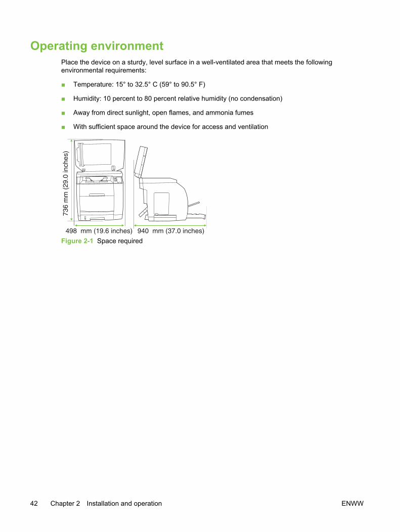
Operating environment Place the device on a sturdy, level surface in a well-ventilated area that meets the followingenvironmental requirements:
■ Temperature: 15° to 32.5° C (59° to 90.5° F)
■ Humidity: 10 percent to 80 percent relative humidity (no condensation)
■ Away from direct sunlight, open flames, and ammonia fumes
■ With sufficient space around the device for access and ventilation
Figure 2-1 Space required
42 Chapter 2 Installation and operation ENWW
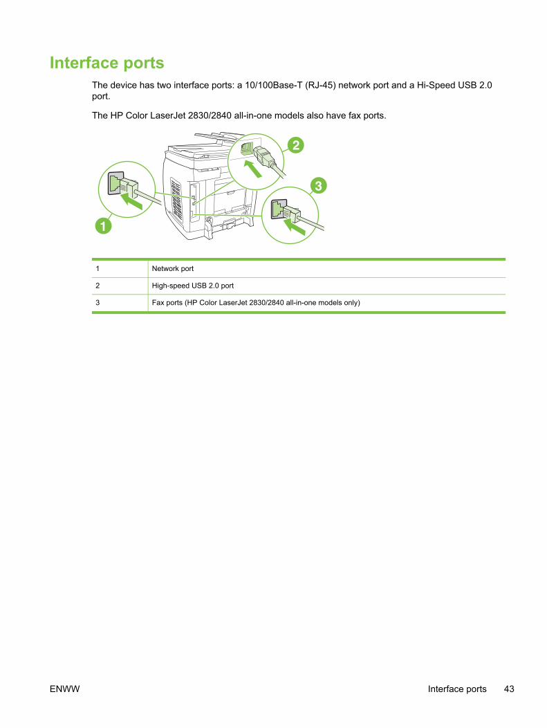
Interface portsThe device has two interface ports: a 10/100Base-T (RJ-45) network port and a Hi-Speed USB 2.0port.
The HP Color LaserJet 2830/2840 all-in-one models also have fax ports.
1 Network port
2 High-speed USB 2.0 port
3 Fax ports (HP Color LaserJet 2830/2840 all-in-one models only)
ENWW Interface ports 43

Control-panel featuresUse the following illustrations to identify the device control-panel components for your device.
Figure 2-2 HP Color LaserJet 2820 all-in-one printer, scanner, copier
1 Alphanumeric buttons. Use the alphanumeric buttons to type data into the device control-panel display orto enter copy quantity.
2 Menu and cancel controls. Use these controls to select menu options, determine the device status, andcancel the current job.
3 Rotate carousel button and status lights. Use these controls to check device status and to rotate theprint-cartridge carousel when replacing cartridges.
4 Copy controls. Use these controls to change commonly used default settings and to start copying.
5 Scan controls. Use these controls to scan to e-mail or to a folder.
Figure 2-3 HP Color LaserJet 2830 all-in-one printer, scanner, fax, copier
1 Fax controls. Use the fax controls to change commonly used fax settings.
2 Alphanumeric buttons. Use the alphanumeric buttons to type data into the device control-panel displayand dial telephone numbers for faxing.
3 Menu and cancel controls. Use these controls to select menu options, determine the device status, andcancel the current job.
4 Rotate carousel button and status lights. Use these controls to check device status and to rotate theprint-cartridge carousel when replacing cartridges.
5 Copy controls. Use these controls to change commonly used default settings and to start copying.
6 Scan controls. Use these controls to scan to e-mail or to a folder.
44 Chapter 2 Installation and operation ENWW

Figure 2-4 HP Color LaserJet 2840 all-in-one printer, scanner, fax, copier
1 Fax controls. Use the fax controls to change commonly used fax settings.
2 Alphanumeric buttons. Use the alphanumeric buttons to type data into the device control-panel displayand dial telephone numbers for faxing.
3 Menu and cancel controls. Use these controls to select menu options, determine the device status, andcancel the current job.
4 Rotate carousel button and status lights. Use these controls to check device status and to rotate theprint-cartridge carousel when replacing cartridges.
5 Copy controls. Use these controls to change commonly used default settings and to start copying.
6 Photo and scan controls. Use these controls to print photos from a memory card, or to scan to e-mail orto a folder.
ENWW Control-panel features 45

Input traysThe HP Color LaserJet 2820/2830/2840 all-in-one comes with one or more input trays.
Table 2-1 Input tray configuration
Device model Standard input trays Optional input trays
HP Color LaserJet 2820 all-in-one tray 1 (125-sheet) tray 2 (250-sheet)
HP Color LaserJet 2830 all-in-one tray 1 (125-sheet) tray 2 (250-sheet)
HP Color LaserJet 2840 all-in-one tray 1 (125-sheet)
tray 2 (250-sheet)
(none)
NOTE Because tray 2 is not included with all models, it is referred to as optional tray 2 in thisdocument.
By default, the device draws first from tray 1. If tray 1 is empty, the device draws from optional tray 2.
46 Chapter 2 Installation and operation ENWW

Output pathsThe device comes with the top output bin and rear output door for printing to a straight-through paperpath. Print jobs emerge from the top output bin when the rear output door is closed. Print jobsemerge from the back of the device when the rear output door is open.
Top output binUse the top output bin when printing most jobs, including jobs on average-weight paper, letterhead,and transparencies. The top output bin can hold up to 125 sheets. Prevent more than 125 sheetsfrom accumulating in the top output bin, or jams can occur.
Rear output binUse the rear output door (straight-through paper path) if problems occur when printing to the topoutput bin, or when printing on such media as cardstock, envelopes, labels, or photo paper. Removeeach sheet as it exits the device.
Figure 2-5 Output paths
1 Top output bin
2 Rear output bin door
ENWW Output paths 47

Loading mediaLoad special print media, such as envelopes, labels, and transparencies, in tray 1 only.
NOTE Because tray 2 is not included for all models, it is referred to as optional tray 2 in thisdocumentation.
Loading tray 1Tray 1 (the multipurpose tray) holds up to 125 sheets of paper or other print media, or it holds up to10 envelopes.
CAUTION Avoid adding print media to tray 1 while the device is printing, or jams can occur.Do not fan paper before loading it into trays, and avoid overloading trays.
To load tray 1
1 Open tray 1.
2 Slide out the tray extender. If the print media being loaded is longer than 23 cm (9 inches), alsoopen the additional tray extender.
3 Slide the media-width guides slightly wider than the print media.
48 Chapter 2 Installation and operation ENWW

4 Place print media into the tray with the side to be printed upon face-up, and the top, short edge infirst.
NOTE If you are manually duplexing, see the device user guide for loading instructions.
5 Slide the media-width guides inward until they lightly touch the print media stack on both sideswithout bending it. Make sure that the print media fits under the tabs on the media-width guides.
CAUTION Wait for the device to finish printing before closing tray 1. Closing the traybefore the device finishes can cause jams.
6 On the back of the device, lower the rear output door if you are printing on special media, suchas labels, envelopes, or heavy or light paper, to prevent curl.
CAUTION Remove each page as it exits the device to avoid a jam error message.
Loading optional tray 2Paper includes average-weight letterhead and prepunched paper. For additional information aboutletterhead and prepunched paper, see the device user guide.
CAUTION Print on special print media such as labels and transparencies from tray 1 only.Printing on special print media from optional tray 2 can cause jams. Do not fan paper beforeloading it into trays, and avoid overloading trays.
ENWW Loading media 49
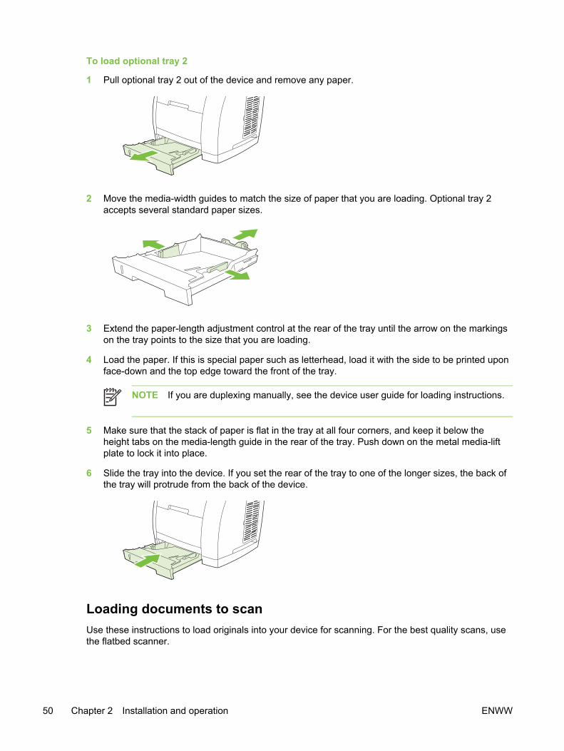
To load optional tray 2
1 Pull optional tray 2 out of the device and remove any paper.
2 Move the media-width guides to match the size of paper that you are loading. Optional tray 2accepts several standard paper sizes.
3 Extend the paper-length adjustment control at the rear of the tray until the arrow on the markingson the tray points to the size that you are loading.
4 Load the paper. If this is special paper such as letterhead, load it with the side to be printed uponface-down and the top edge toward the front of the tray.
NOTE If you are duplexing manually, see the device user guide for loading instructions.
5 Make sure that the stack of paper is flat in the tray at all four corners, and keep it below theheight tabs on the media-length guide in the rear of the tray. Push down on the metal media-liftplate to lock it into place.
6 Slide the tray into the device. If you set the rear of the tray to one of the longer sizes, the back ofthe tray will protrude from the back of the device.
Loading documents to scanUse these instructions to load originals into your device for scanning. For the best quality scans, usethe flatbed scanner.
50 Chapter 2 Installation and operation ENWW

To load originals onto the flatbed scanner
1 Make sure that the automatic document feeder (ADF) contains no media.
2 Lift the flatbed scanner cover.
3 Place the original document face-down on the flatbed scanner with the upper-left corner of thedocument at the lower-right corner of the glass.
4 Gently close the lid.
The document is ready to be scanned.
CAUTION To prevent damaging the device, do not allow the scanner lid to fall onto theflatbed scanner surface. Always close the scanner lid when the device is not in use.
To load originals into the automatic document feeder (ADF)
NOTE The ADF capacity is up to 50 sheets of 75 g/m2 (20 lb) media.
The minimum size for media in the ADF is 127 by 127 mm (5 by 5 inches). For smaller sizes,use the flatbed scanner. The maximum size for media in the ADF is 216 by 381 mm (8.5 by 15inches).
1 Make sure that the flatbed scanner contains no media.
2 Close the flatbed scanner cover and put the top end of the stack of originals into the ADF inputtray, with the media stack face-up and the first page to be copied on top of the stack.
CAUTION To prevent damaging the device, do not use an original that containscorrection tape, correction fluid, paper clips, or staples. Also, do not load photographs,small originals, or fragile originals into the ADF.
3 Slide the stack into the ADF until it does not move any farther.
The control panel displays the message Document Loaded.
ENWW Loading media 51

4 Adjust the media guides until they are snug against the media.
5 The document is now ready to be copied.
52 Chapter 2 Installation and operation ENWW

HP ToolboxHP Toolbox is a Web application that you can use for the following tasks:
■ Check the device status.
■ Configure the device settings.
■ View troubleshooting information.
■ View online documentation.
NOTE HP Toolbox is not supported for Windows 98 SE, Windows Me, Windows NT, andMacintosh operating systems (see Software and supported operating systems). To useHP Toolbox, you must have TCP/IP protocol installed on your computer.
NOTE You do not have to have Internet access to open and use HP Toolbox. However, ifyou click a link in the Other Links area, you must have Internet access to go to the site that isassociated with the link. See Other links for more information.
Viewing HP ToolboxYou can view HP Toolbox when the device is directly connected to your computer or when it isconnected to the network. You must perform a complete software installation to use HP Toolbox.
To view HP Toolbox
1 Open HP Toolbox in one of these ways:
● In the Windows system tray, double-click the HP ToolboxDevice Status and Alerts icon.
● On the Windows Start menu, click Programs (or All Programs in Windows XP), click HP,click HP Color LaserJet 2820/2830/2840, and then click HP Toolbox.
NOTE After you open the URL, you can bookmark it so that you can return to it quicklyin the future.
2 HP Toolbox opens in a Web browser. The HP Toolbox software contains the following sections:
● Status tab
● Fax tab
● Scan to tab
● Troubleshooting tab
● Documentation tab
● Device Settings pages
● HP Toolbox links
● Other links
ENWW HP Toolbox 53

Status tabThe Status tab contains links to the following main pages:
■ Device Status. View device status information. This page indicates device conditions such as ajam or an empty tray. After you correct a problem with the device, click Refresh Status to updatethe device status.
■ Supplies Status. View detailed supplies status such as the estimated percent of toner remainingin the print cartridge and the number of pages that have been printed with the current printcartridge. This page also has links to order supplies and to find recycling information.
■ Set up Status Alerts. Set up the device to send you pop-up alerts for certain events, such aslow toner levels.
■ Set up E-mail Alerts. Set up the device to send you e-mail alert messages for certain events,such as low toner levels.
■ Device Configuration. View a detailed description of the current device configuration, includingthe amount of memory installed and whether optional trays are installed.
■ Network Configuration. View a detailed description of the current network configuration,including the IP address and network status. This link appears only if the device is connected toa network.
■ Print Info Pages. Print the Configuration page and various other information pages that areavailable for the device, such as the Supplies Status page and the Demo page.
■ Event Log. View a history of device errors. The most recent error is at the top of the list.
Fax tabUse the Fax tab to perform fax tasks from your computer. The Fax tab contains links to the followingmain pages:
■ Fax Tasks. Perform such tasks as sending a fax or clearing the fax memory, or set the faxreceive mode.
■ Fax Phone Book. Add, edit, or delete entries in the device phone book.
■ Fax Send Log. View all of the recent faxes that have been sent from the device.
■ Fax Receive Log. View all of the recent faxes that have been received by the device.
■ Fax Data Properties. Manage the space used to store faxes on your computer. These settingsapply only if you have chosen to send or receive faxes remotely from your computer.
■ Fax Reports. Print any or all of the fax reports from your computer.
■ Detailed Fax Settings. Use links to the Fax Setup Wizard or the Fax Settings tab to changethe device fax settings.
■ How Do I?. View Help topics for device fax tasks.
54 Chapter 2 Installation and operation ENWW

Scan to tabUse the Scan to tab to set up the device SCAN TO button. The SCAN TO button allows you to scanfrom the device, rather than scanning from a software program on your computer.
NOTE The HP Color LaserJet 2830 all-in-one printer, scanner, fax, copier has a SCAN TO
EMAIL button that you can also set up with this tab.
The Scan to tab contains links to the following main pages:
■ Scan to E-mail or Folder. Activate or deactivate the scan-to feature. You also can add, edit, ordelete destination e-mail addresses or folders for this feature.
■ Scan Preferences. Change the scan preference settings for the device scan-to feature,including scan resolution and file type.
■ How Do I?. View Help topics for device tasks that involve the SCAN TO or SCAN TO EMAIL (HP ColorLaserJet 2830 all-in-one only).
Troubleshooting tabThe Troubleshooting tab contains links to the following main pages:
■ Control Panel Messages. View descriptions of device control-panel messages.
■ Clearing Jams. View information about locating and clearing jams.
■ Print Problems. View Help topics that can help you solve print problems.
■ Scan Problems. View Help topics that can help you solve scan problems.
■ Copy Problems. View Help topics that can help you solve copy problems.
■ Fax Problems. View Help topics that can help you solve fax problems.
■ Memory Card Problems. View Help topics that can help you solve memory-card problems.
■ Connectivity Problems. View Help topics that can help you solve networking problems.
■ Troubleshooting Tools. Employ such troubleshooting tools as a cleaning page or a colortroubleshooting page to maintain the device.
■ Animated Demonstrations. View animated Help demonstrations for the device.
Documentation tabThe Documentation tab contains links to the following main pages:
■ Print: How Do I? View the How Do I? Help for print problems.
■ Fax: How Do I? View the How Do I? Help for fax problems.
■ Copy: How Do I? View the How Do I? Help for copy problems.
■ Scan: How Do I? View the How Do I? Help for scan problems.
ENWW HP Toolbox 55
■ Photo: How Do I? View the How Do I? Help for memory-card problems.
■ Network: How Do I? View the How Do I? Help for network problems.
■ Other: How Do I? View the How Do I? Help for other device problems.
■ User Guide. View information about the device usage, warranty, specifications, and support thatyou are currently reading. The device User Guide is available in both HTML and PDF format.
■ Readme. View important information about the device that is not available in the device userguide. The late-breaking readme contains last-minute information about the device (in Englishonly).
Device Settings pagesWhen you click the Device Settings button, HP Toolbox displays the device settings available foryour device. The Device Settings screen has the following tabs:
■ System Settings
■ Print Settings
■ Fax Settings
■ Copy Settings
■ Network Settings
NOTE Printer driver settings can override settings that are made in HP Toolbox.
System Settings tabThe System Settings tab contains links to the following main pages:
■ Device Information. View information about the device, such as the device description and acontact person.
■ Paper Handling. Change the device paper-handling settings, such as default paper size anddefault paper type.
■ Print Quality. Change the device print-quality settings, such as color calibration and grayscaleprinting.
■ Print Density. Change the device print-density settings, such as contrast and shadows.
■ Print Modes. Change the device mode settings for a each media type, such as letterhead,prepunched, or glossy paper.
■ System Setup. Change the device system settings, such as device language and jam recovery.
■ Volumes. Change the device volume settings, such as the telephone line (HP Color LaserJet2830/2840 all-in-one models only) and alarm volumes.
■ Date/Time. Change the device date and time settings.
■ Service. Gain access to various procedures required to maintain the device.
56 Chapter 2 Installation and operation ENWW

■ Device Polling. Change the device polling settings, which determine how often HP Toolboxcollects data from the device.
■ Save/Restore Settings. Save the current settings for the device to a file on your computer. Usethis file to load the same settings onto another device or to restore these settings to this device ata later time.
Print Settings tabThe Print Settings tab contains links to the following main pages:
■ Printing. Change the default device print settings, such as number of copies and paperorientation.
■ PCL6. View and change the PCL6 settings.
■ PostScript. View and change the PS settings.
■ Memory Card. View and change the default device memory-card settings (HP Color LaserJet2840 all-in-one only).
Fax Settings tabThe Fax Settings tab contains links to the following main pages:
■ General. Change such basic fax settings as the fax header and error reporting.
■ Fax Send. Change such fax send settings as resolution and redial.
■ Fax Receive. Change such fax receive settings as the answer mode and the fit-to-page option.
■ Fax Setup Wizard. Start the Fax Setup Wizard to set up the device fax settings.
Copy Settings tabThe Copy Settings tab contains links to the following main pages:
■ Copy. Change such default copy settings as number of copies and contrast.
■ Reduce/Enlarge. Change the reduction-enlargement settings for the device.
Network Settings tab
NOTE The Network Settings tab appears only if the device is connected to a network.
The network administrator can use the Network Settings tab to control the network-related settingsfor the device when it is connected to an IP-based network.
ENWW HP Toolbox 57

HP Toolbox linksThe HP Toolbox links at the left of the screen provide links to the following options:
■ Select a device. Select from all of the HP Toolbox-enabled devices.
■ View current alerts. View the current alerts for all devices that have been set up. (You must beprinting to view the current alerts.)
■ Text only page. View HP Toolbox as a site map that links to text-only pages.
Other linksThis section contains links that connect you to the Internet. You must have Internet access in orderto use any of these links. If you use a dial-up connection and did not connect when you first openedHP Toolbox, you must connect before you can visit these Web sites. Connecting might require thatyou close HP Toolbox and reopen it.
■ HP Instant Support. View the HP Instant Support Web site.
■ Product Registration. View the HP product registration Web site.
■ Order Supplies. Order device supplies at the HP Web site.
■ Product Support. View the support site for the HP Color LaserJet 2820/2830/2840 all-in-one. Atthe site, you can search for help with a specific problem.
58 Chapter 2 Installation and operation ENWW

Embedded Web serverThis device is equipped with an embedded Web server, which allows access to information aboutdevice and network activities. A Web server provides an environment in which web programs mayrun, much in the same way that an operating system, such as Windows, provides an environment forprograms to run on your computer. The output from these programs can then be displayed by a Webbrowser, such as Microsoft Internet Explorer, Safari, or Netscape Navigator.
An embedded Web server resides on a hardware device (such as a printer) or in firmware, ratherthan as software that is loaded on a network server.
The advantage of an embedded Web server is that it provides an interface to the device that anyonewith a network-connected computer and a standard Web browser can access. There is no specialsoftware to install or configure, but you must have a supported Web browser on your computer. Toaccess the embedded Web server, type the IP address for the device in the address line of thebrowser. (To find the IP address, print a Configuration page. For more information about printing aConfiguration page, see Configuration page.
NOTE For Macintosh operating systems, you can use the EWS over a USB connection.
FeaturesThe HP embedded Web server allows you to view device and network card status and manageprinting functions from your computer. With the HP embedded Web server, you can do the following:
■ View device status information
■ Determine the remaining life on all supplies and order new ones
■ View and change tray configurations
■ View and change the device control-panel menu configuration
■ View and print internal pages
■ Add or customize links to other Web sites
■ Select the language in which to display the embedded Web server pages
■ View and change network configuration
■ View support content that is device-specific and specific to the current device state
ENWW Embedded Web server 59

60 Chapter 2 Installation and operation ENWW

3 Maintenance
Chapter contents● Life expectancies of components
● Cleaning the device
● Managing supplies
ENWW Chapter contents 61

Life expectancies of componentsInspect supplies when you service the device. Replace components as needed, based on failure orwear, rather than on usage.
The following table lists approximate schedules for replacing supplies.
Table 3-1 Life expectancies of components
Description Part number Estimated life (in numberof pages at 5 percentcoverage1)
Remarks
Print cartridge, black (userreplaceable)
Q3960-67901
Q3960-67902 (EMEA)
5,000
Print cartridge, cyan (userreplaceable)
Q3971-67901
Q3971-67902 (EMEA)
2,000
Print cartridge, cyan (userreplaceable)
Q3961-67901
Q3961-67902 (EMEA)`
4,000 High-capacity cartridge
Print cartridge, yellow (userreplaceable)
Q3972-67901
Q3972-67902 (EMEA)
2,000
Print cartridge, yellow (userreplaceable)
Q3962-67901
Q3962-67902 (EMEA)
4,000 High-capacity cartridge
Print cartridge, magenta(user replaceable)
Q3973-67901
Q3973-67902 (EMEA)
2,000
Print cartridge, magenta(user replaceable)
Q3963-67901
Q3963-67902 (EMEA)
4,000 High-capacity cartridge
Imaging drum Q3964-67901 20,000 (black only)
5,000 (color)
The average life is 6,000 to8,000 pages.
Transfer roller RF5-4067-000CN 100,000 Can affect print quality andpaper movement.
Device pickup roller RB3-0160-000CN 100,000 Look for glazing and/orcracks.
Device separation pad RF5-4012-000 100,000 Can affect documentmovement.
Fuser assembly, 110-127 V) RG5-7602-000 100,000 Can affect print quality anddocument movement.
Fuser assembly, 220-240 V) RG5-7603-000 100,000 Can affect print quality anddocument movement.
Separation pad, optionaltray 2
RB2-9960-000 100,000 Can affect documentmovement.
ADF pickup roller Q3948-67903 50,000 Can affect documentmovement.
62 Chapter 3 Maintenance ENWW

Description Part number Estimated life (in numberof pages at 5 percentcoverage1)
Remarks
ADF separation pad Q3948-67904 50,000 Can affect documentmovement.
ADF assembly Q3948–60189 50,000
Scanning assembly Q3948–60191 50,000
1 The estimated print-cartridge life is based on letter- or A4-sized paper with an average of 5% toner coverage and amedium density setting.
Table 3-1 Life expectancies of components (continued)
ENWW Life expectancies of components 63
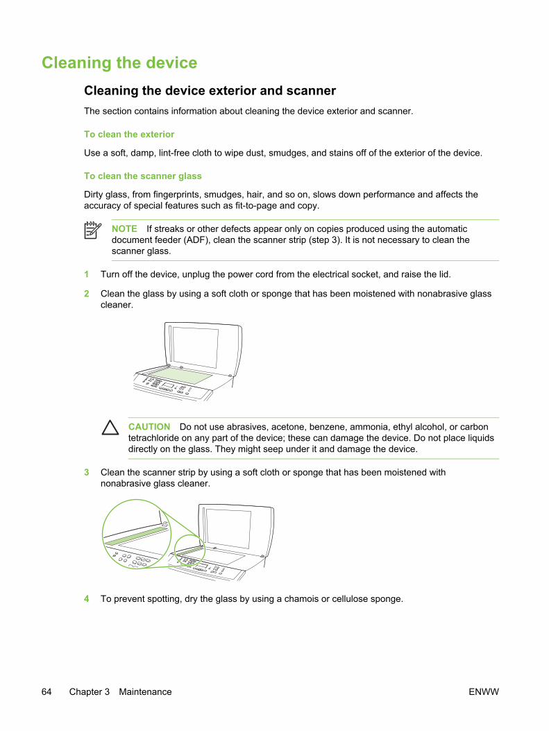
Cleaning the deviceCleaning the device exterior and scannerThe section contains information about cleaning the device exterior and scanner.
To clean the exterior
Use a soft, damp, lint-free cloth to wipe dust, smudges, and stains off of the exterior of the device.
To clean the scanner glass
Dirty glass, from fingerprints, smudges, hair, and so on, slows down performance and affects theaccuracy of special features such as fit-to-page and copy.
NOTE If streaks or other defects appear only on copies produced using the automaticdocument feeder (ADF), clean the scanner strip (step 3). It is not necessary to clean thescanner glass.
1 Turn off the device, unplug the power cord from the electrical socket, and raise the lid.
2 Clean the glass by using a soft cloth or sponge that has been moistened with nonabrasive glasscleaner.
CAUTION Do not use abrasives, acetone, benzene, ammonia, ethyl alcohol, or carbontetrachloride on any part of the device; these can damage the device. Do not place liquidsdirectly on the glass. They might seep under it and damage the device.
3 Clean the scanner strip by using a soft cloth or sponge that has been moistened withnonabrasive glass cleaner.
4 To prevent spotting, dry the glass by using a chamois or cellulose sponge.
64 Chapter 3 Maintenance ENWW
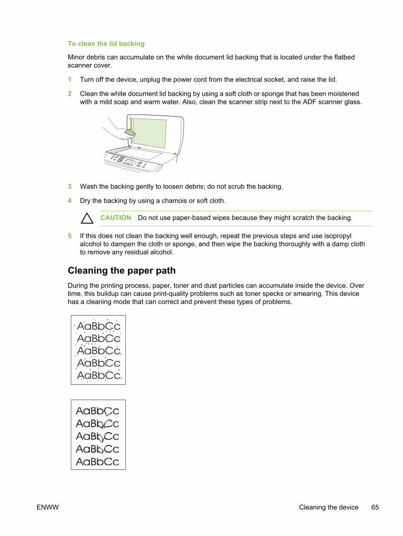
To clean the lid backing
Minor debris can accumulate on the white document lid backing that is located under the flatbedscanner cover.
1 Turn off the device, unplug the power cord from the electrical socket, and raise the lid.
2 Clean the white document lid backing by using a soft cloth or sponge that has been moistenedwith a mild soap and warm water. Also, clean the scanner strip next to the ADF scanner glass.
3 Wash the backing gently to loosen debris; do not scrub the backing.
4 Dry the backing by using a chamois or soft cloth.
CAUTION Do not use paper-based wipes because they might scratch the backing.
5 If this does not clean the backing well enough, repeat the previous steps and use isopropylalcohol to dampen the cloth or sponge, and then wipe the backing thoroughly with a damp clothto remove any residual alcohol.
Cleaning the paper pathDuring the printing process, paper, toner and dust particles can accumulate inside the device. Overtime, this buildup can cause print-quality problems such as toner specks or smearing. This devicehas a cleaning mode that can correct and prevent these types of problems.
ENWW Cleaning the device 65
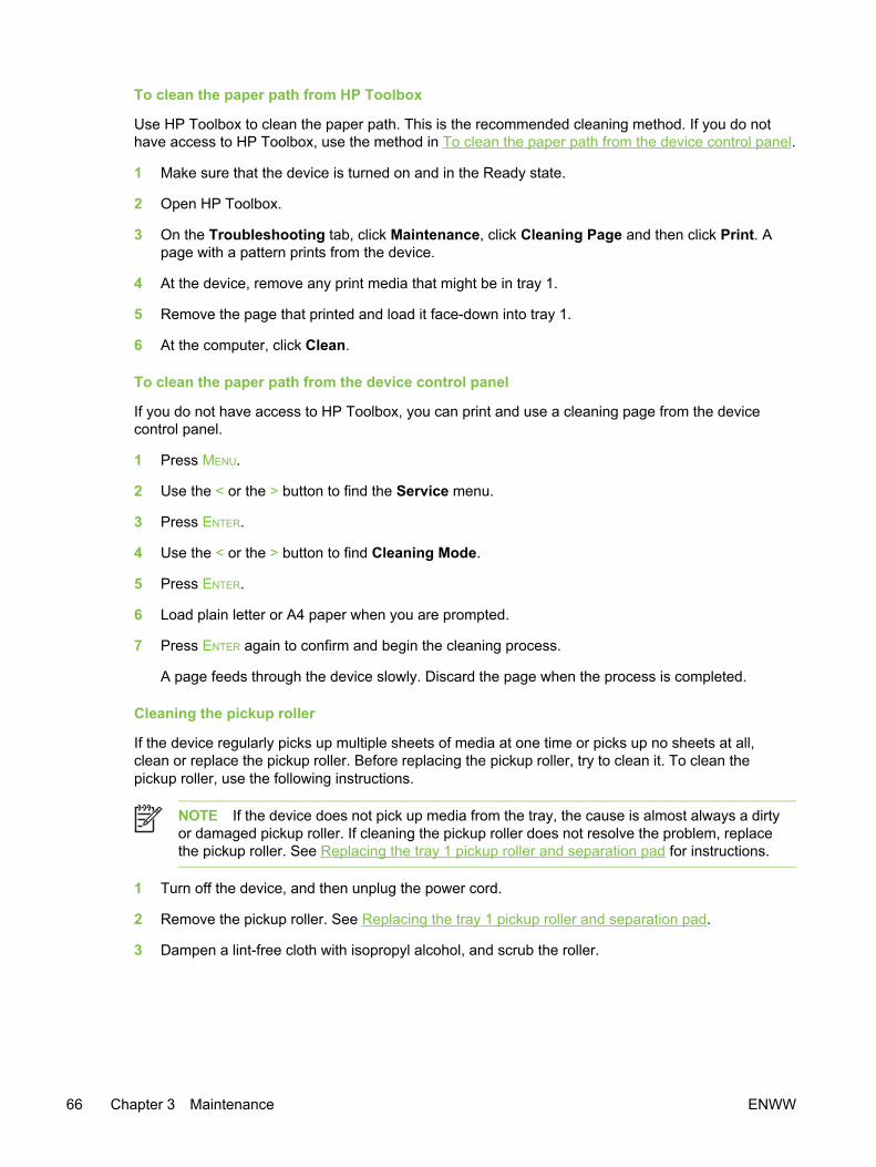
To clean the paper path from HP Toolbox
Use HP Toolbox to clean the paper path. This is the recommended cleaning method. If you do nothave access to HP Toolbox, use the method in To clean the paper path from the device control panel.
1 Make sure that the device is turned on and in the Ready state.
2 Open HP Toolbox.
3 On the Troubleshooting tab, click Maintenance, click Cleaning Page and then click Print. Apage with a pattern prints from the device.
4 At the device, remove any print media that might be in tray 1.
5 Remove the page that printed and load it face-down into tray 1.
6 At the computer, click Clean.
To clean the paper path from the device control panel
If you do not have access to HP Toolbox, you can print and use a cleaning page from the devicecontrol panel.
1 Press MENU.
2 Use the < or the > button to find the Service menu.
3 Press ENTER.
4 Use the < or the > button to find Cleaning Mode.
5 Press ENTER.
6 Load plain letter or A4 paper when you are prompted.
7 Press ENTER again to confirm and begin the cleaning process.
A page feeds through the device slowly. Discard the page when the process is completed.
Cleaning the pickup roller
If the device regularly picks up multiple sheets of media at one time or picks up no sheets at all,clean or replace the pickup roller. Before replacing the pickup roller, try to clean it. To clean thepickup roller, use the following instructions.
NOTE If the device does not pick up media from the tray, the cause is almost always a dirtyor damaged pickup roller. If cleaning the pickup roller does not resolve the problem, replacethe pickup roller. See Replacing the tray 1 pickup roller and separation pad for instructions.
1 Turn off the device, and then unplug the power cord.
2 Remove the pickup roller. See Replacing the tray 1 pickup roller and separation pad.
3 Dampen a lint-free cloth with isopropyl alcohol, and scrub the roller.
66 Chapter 3 Maintenance ENWW

4 Using a dry lint-free cloth, wipe the pickup roller to remove loosened dirt.
Figure 3-1 Cleaning the pickup roller (1 of 2)
5 Allow the pickup roller to dry completely, and then reinstall it in the device.
Figure 3-2 Cleaning the pickup roller (2 of 2)
6 Reconnect the device power cord, and then turn on the device.
Cleaning the separation pad
1 Turn off the device, and then unplug the power cord.
2 Remove the separation pad. See Replacing the tray 1 pickup roller and separation pad.
3 Dampen a lint-free cloth with isopropyl alcohol, and scrub the separation pad.
4 Reinstall the separation pad.
5 Plug in the device, and then turn on the device.
ENWW Cleaning the device 67
Managing suppliesFor warranty information about these supplies, see Print Cartridge and Imaging Drum LimitedWarranty Statement.
Supplies lifeThe life of the imaging drum depends on the number of black-only or color pages that print jobsrequire. Imaging-drum life is also affected each time the device calibrates because calibrating causesthe imaging drum to rotate. Imaging-drum life is measured in terms of number of rotations rather thannumber of pages printed.
The type and length of print jobs also affects drum life. A series of short print jobs uses more drumlife than an equivalent number of pages printed in a single large job. To extend drum life, printmultiple copies of a print job at one time rather than sending the same job to the device multiple times.
The life of a print cartridge depends on the amount of toner that print jobs require. When printing textat 5% coverage, black print cartridges last an average of 5,000 pages and cyan, magenta, andyellow print cartridges last an average of 2,000 pages. High-capacity cyan, magenta, and yellow printcartridges last an average of 4,000 pages. (A typical business letter has 5% coverage.)
Checking and ordering suppliesYou can check the supplies status by using the device control panel, printing a Supplies Status page,or viewing HP Toolbox. Hewlett-Packard recommends that you place an order for a replacementprint cartridge when you first receive the Low message for a print cartridge. The Low messageindicates that approximately two weeks of life remain. When you use a new, authentic HP printcartridge or imaging drum, you can obtain the following types of supplies information:
■ Amount of cartridge or drum life remaining
■ Estimated number of pages that can be printed
■ Number of pages printed
■ Other supplies information
NOTE If the device is connected to the network, you can set HP Toolbox to notify you by e-mail when a print cartridge is low or the imaging drum is near the end of its useful life. If thedevice is directly connected to a computer, you can set HP Toolbox to notify you whensupplies are low.
To check status and order supplies using the control panelDo one of the following:
■ Check the messages on the device control panel. These messages indicate when a printcartridge or the imaging drum is low or empty. The control panel also indicates when a non-HP print cartridge is first installed. See Control-panel messages.
■ Print a Supplies Status page. Check the supplies levels on the Supplies Status page.
If the supplies levels are low, you can order supplies through your local HP dealer, by telephone, oronline. See Parts and diagrams for part numbers. See www.hp.com/go/ljsupplies to order online.
68 Chapter 3 Maintenance ENWW

To check status and order supplies using the HP ToolboxYou can configure the HP Toolbox to notify you when the supplies are low. You can choose toreceive alerts by e-mail or as a pop-up message or taskbar icon. To order supplies by using theHP Toolbox, in the Other Links area, click Order supplies.
For more information, see Other links.
Storing suppliesFollow these guidelines for storing print cartridges and the imaging drum:
■ Do not remove the print cartridge or imaging drum from its package until you are ready to use it.
CAUTION To prevent damage, do not expose the print cartridge or imaging drum to lightfor more than a few minutes.
■ See Table 1-6 Environmental specifications for operating- and storage-temperature ranges.
■ Store the supply in a horizontal position.
■ Store the supply in a dark, dry location away from heat and magnetic sources.
Replacing and recycling suppliesTo install a new HP print cartridge or imaging drum, follow the instructions included in the box thatcontains the new supply, or see the device getting started guide.
To recycle supplies, place the used supply in the box in which the new supply arrived. Use theenclosed return label to send the used supply to HP for recycling. For complete information, see therecycling guide that is included with each new HP supply item. See HP Printing Supplies Returnsand Recycling Program information for more information about HP's recycling program.
HP policy for non-HP suppliesHewlett-Packard Company cannot recommend the use of non-HP supplies, either new orremanufactured. Because they are not HP products, HP cannot influence their design or control theirquality. Service or repairs that are required as a result of using a non-HP supply will not be coveredunder the device warranty.
When you insert a supply into the device, the device informs you if the supply is not a genuineHP supply. If you insert a genuine HP supply that has reached the low state from another HP device,the device identifies the supply as non-HP. Simply return the supply to the original device toreactivate HP features and functionality.
Resetting the device for non-HP suppliesWhen you install a non-HP print cartridge or imaging drum, the light next to the print cartridge orimaging drum you replaced blinks and the Attention light is on. In order to print with this supply, youmust press CANCEL the first time you install this non-HP supply. The control-panel display will notindicate when this type of supply is low or empty.
CAUTION The device will not stop printing when a non-HP supply is empty. Device damagecan occur if the device attempts to print with an empty print cartridge or imaging drum.
ENWW Managing supplies 69

HP fraud hotlineCall the HP fraud hotline if the supplies status lights indicate that the print cartridge or imaging drumis not an HP product and you think that it is genuine. Hewlett-Packard will help determine if theproduct is genuine and take steps to resolve the problem.
Your print cartridge or imaging drum might not be a genuine HP product if you notice the followingissues:
■ You are experiencing a large number of problems with the print cartridge or imaging drum.
■ The print cartridge or imaging drum does not look like an HP product usually does (for example,the pull tab or the box is different).
In the United States, call toll-free: 877-219-3183.
Outside the United States, you can call collect. Dial the operator and ask to place a collect call to thistelephone number: 770-263-4745. If you do not speak English, a representative at the HP fraudhotline who speaks your language will assist you. Or, if someone who speaks your language is notavailable, a language line interpreter will connect approximately one minute after the beginning of thecall. The language line interpreter is a service that translates between you and the representative forthe HP fraud hotline.
70 Chapter 3 Maintenance ENWW

4 Theory of operation
Chapter contents● Introduction
● Engine control system
● Laser/scanner system
● Pickup and feed system
● Image-formation system
● Scanner and ADF functions and operation
● Fax functions and operation
ENWW Chapter contents 71

IntroductionThis chapter presents an overview of the relationships between major components in the device, andincludes a detailed discussion of the image-formation system. The following systems are discussed:
■ Engine control system
■ Laser/scanner system
■ Pickup and feed system
■ Image-formation system
■ Scanner and ADF functions and operation
■ Fax functions and operation
NOTE The service CD-ROM contains sound files of normal device operations. Refer tothose files if you are in doubt of what a "normal" device should sound like.
72 Chapter 4 Theory of operation ENWW

ENWW Introduction 73

Figure 4-1 Cross-section of the device
74 Chapter 4 Theory of operation ENWW

Table 4-1 Device systems
Ref Description Part number Qty
1 Laser/scanner RG5-6890-000CN
2 Developing cylinder roll (contained in print cartridge)
3 Photosensitive drum (contained in imaging drum)
4 Primary charging roller (contained in imaging drum)
5 Imaging drum Q3964A
6 Transfer belt (contained in imaging drum)
7 Density sensor RH7-7158-000CN
8 Primary transfer roller (contained in imaging drum)
9 Transfer-belt cleaning roller (contained in imaging drum)
10 Registration shutter (contained in registration rollerassembly)
11 Pickup roller RG5-6952-000CN
12 Tray 1 RG5-7601-000CN
13 Separation pad RF5-4012-000CN
14 Registration roller RG5-6939-000CN
15 Secondary transfer roller RF5-4067-000CN
16 Auxiliary transfer-belt cleaning roller (contained in imaging drum)
17 Feed belts (8) RB3-0063-000CN
18 Carousel RG5-7587-000CN
19 Print cartridge (several; see Table 7-2Accessories for part numbers)
20 Fusing film (contained in fuser)
21 Pressure roller (contained in fuser)
22 Fuser delivery roller (contained in fuser)
23 Face-down delivery rollers RG5-7595-000CN (lower) andRG5-7637-000CN (upper)
ENWW Introduction 75

Engine control systemThe engine control system coordinates all device functions. It drives the laser/scanner system, theimage formation system, and the pickup and feed system.
The engine control system contains the following components:
■ DC controller
■ High-voltage power-supply PCA
■ Low-voltage power unit:
■ Fuser-control circuit
■ Low-voltage power-supply PCA
Figure 4-2 Engine control system (includes the basic configuration of the device)
Basic sequence of operationOperation sequences are controlled by the CPU in the DC controller in the engine control system.Table 4-2 Basic sequence of operation describes engine operations for each period of a printoperation.
Table 4-2 Basic sequence of operation
Period Duration Purpose Remarks
WAIT (wait) From the time the powerswitch is turned on untiltransfer-belt cleaning iscomplete.
Clears potential from thedrum surface and cleans thetransfer belt.
See Figure 4-3 Power-onsequence for a completedescription of the WAIT(power-on) period.
STBY (standby) From the end of the WAIT orLSTR period until either aprint command is sent fromthe formatter or the power isturned off.
Prepares the device toreceive print commands.
INTR (initial rotation) From the time of the printcommand until detection ofthe HP1 (transfer-belt home-
Prepares the photosensitivedrum for printing.
76 Chapter 4 Theory of operation ENWW

Period Duration Purpose Remarks
position detection) signal forthe first color.
PRINT (print) From the end of the INTRperiod until detection of thetransfer-belt home-positionsignal for the secondarytransfer.
Forms the image on thephotosensitive drum andtransfers the toner image tothe transfer belt.
LSTR (last rotation) From the end of the PRINTperiod until the main motorstops rotating.
Transfers the toner imageon the transfer belt to themedia and delivers theprinted media.
After LSTR, the devicereturns to STBY.
Table 4-2 Basic sequence of operation (continued)
ENWW Engine control system 77
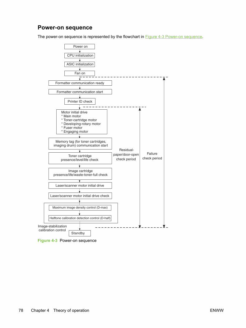
Power-on sequenceThe power-on sequence is represented by the flowchart in Figure 4-3 Power-on sequence.
Figure 4-3 Power-on sequence
78 Chapter 4 Theory of operation ENWW

Motors and fans
Figure 4-4 Motors and fans
Table 4-3 Motors and fans
Reference Description Part number
1 Engaging motor RH7-1629-000CN
2 Developing-rotary motor RH7-1651-000CN
3 Toner-cartridge motor RH7-1625-000CN
4 Fuser motor RH7-1628-000CN
5 Main motor RH7-4063-000CN
6 Cooling fan RH7-1630-000CN
ENWW Engine control system 79
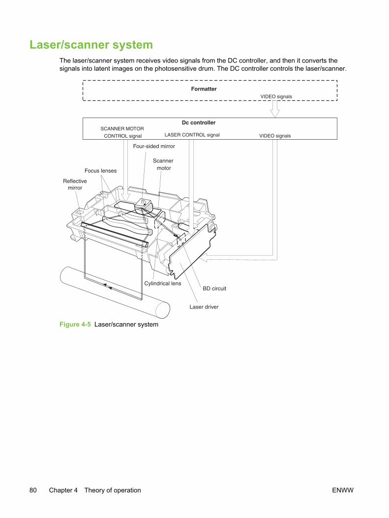
Laser/scanner systemThe laser/scanner system receives video signals from the DC controller, and then it converts thesignals into latent images on the photosensitive drum. The DC controller controls the laser/scanner.
Figure 4-5 Laser/scanner system
80 Chapter 4 Theory of operation ENWW

Pickup and feed systemThe pickup and feed system consists of several types of feed rollers and sensors. The DC controllerdrives the paper and feed system by controlling two motors, two clutches, and the solenoid.
Two photo-interrupters (PS1 and PS711) detect media as it passes. If media does not reach or passeach sensor within the specified time period, the DC controller determines that a jam has occurredand alerts the video controller circuit.
The following components are identified in Figure 4-6 Pickup and feed system:
■ PS1 fusing-delivery paper sensor
■ PS711 registration paper sensor
■ PS718 tray 1 (multipurpose tray) paper sensor
■ PS720 fuser wrap-jam sensor
■ DCM701 main motor
■ PM702 fuser motor
■ SL92 tray 1 pickup solenoid
■ CL1 registration clutch
■ CL2 roller-engaging clutch
ENWW Pickup and feed system 81
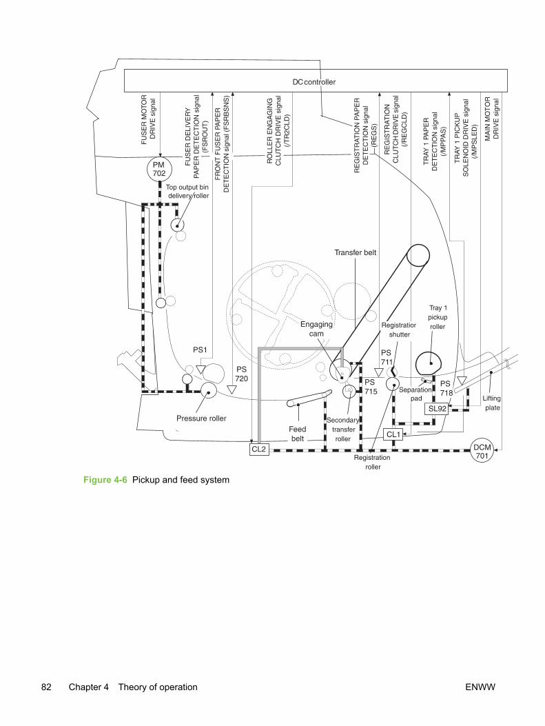
Figure 4-6 Pickup and feed system
82 Chapter 4 Theory of operation ENWW
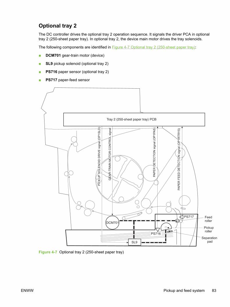
Optional tray 2The DC controller drives the optional tray 2 operation sequence. It signals the driver PCA in optionaltray 2 (250-sheet paper tray). In optional tray 2, the device main motor drives the tray solenoids.
The following components are identified in Figure 4-7 Optional tray 2 (250-sheet paper tray):
■ DCM701 gear-train motor (device)
■ SL9 pickup solenoid (optional tray 2)
■ PS716 paper sensor (optional tray 2)
■ PS717 paper-feed sensor
Figure 4-7 Optional tray 2 (250-sheet paper tray)
ENWW Pickup and feed system 83
Jam detectionThe registration sensor (PS711) and the fuser sensor (PS1) detect media that is moving through thedevice. If a jam is detected, the DC controller immediately stops the printing process and sends amessage to the video controller circuit.
A jam can be detected under any of the following conditions:
■ Pickup delay jam. The leading edge of the print media does not reach the registration sensor(PS711) within 1.1 seconds (tray 1) or 1.7 seconds (optional tray 2).
■ Pickup stationary jam. The registration clutch is on, and the registration sensor (PS711) does notdetect the trailing edge of the media within 3.4 seconds after the start of a re-pickup operation.
■ Fuser wrap-jam. The main CPU detects media inside the fuser front sensor (PS720) when thepower is turned on or after the top cover is closed.
■ Delivery delay jam. The registration clutch is on, and the fuser-delivery sensor (PS1) does notdetect the leading edge of the media within 2.3 seconds after the start of a re-pickup operation.
■ Delivery stationary jam. The leading edge of media does not pass the fuser-delivery sensor(PS1) within 2.4 seconds after it has passed the registration sensor (PS711).
■ Door-open jam. The main CPU detects that the top cover is open during a print operation.
■ Residual jam. The main CPU detects one or more of the following conditions:
■ Power is turned on.
■ The device door is closed after a jam occurrence.
■ The registration sensor (PS711) and fusing-delivery sensor (PS1) detect media.
■ Paper pickup failure. The sensor (PS717) near the feed roller does not detect media movingthrough the device.
84 Chapter 4 Theory of operation ENWW

Photosensors and switches
Figure 4-8 Photosensors and switches (1 of 2)
Figure 4-9 Photosensors and switches (2 of 2)
Table 4-4 Photosensors and switches
Reference Table (itemnumber)
Description Part number
1 7-17 (23) Tray 1 sensor WG8–5593–000CN
2 7-14 (A21) Roller-engaging sensor1 RG5-7579-000CN
3 7-15 (A62) Developing-rotary-engaging sensor1 RG5-7589-000CN
4 7-17 (A14) Fuser-delivery sensor1 RG3-7602-000CN (110 V)
RG5-7608-000CN (220 V)
5 7-17 (38) Front fuser-detection sensor WG8-5593-000CN
6 7-10 (9) Door-open detection switch RH7-6051-000CN
ENWW Pickup and feed system 85

Reference Table (itemnumber)
Description Part number
7 7-18 Power switch1 RH3-2260-000CN (110 V)
RH3-2261-000CN (220 V)
1 This part can be ordered only as part of an assembly. The part number listed is the part number for the assembly.
Table 4-4 Photosensors and switches (continued)
86 Chapter 4 Theory of operation ENWW
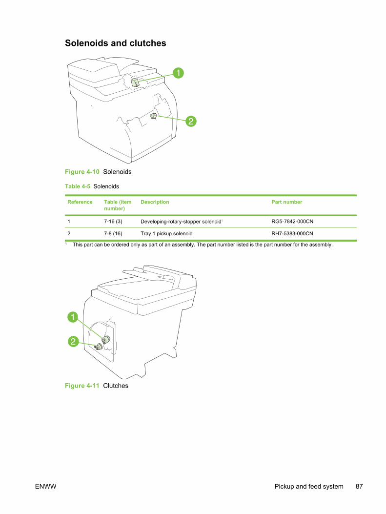
Solenoids and clutches
Figure 4-10 Solenoids
Table 4-5 Solenoids
Reference Table (itemnumber)
Description Part number
1 7-16 (3) Developing-rotary-stopper solenoid1 RG5-7842-000CN
2 7-8 (16) Tray 1 pickup solenoid RH7-5383-000CN
1 This part can be ordered only as part of an assembly. The part number listed is the part number for the assembly.
Figure 4-11 Clutches
ENWW Pickup and feed system 87

Table 4-6 Clutches
Reference Table (itemnumber)
Description Part number
1 7-14 (3) Roller-engaging clutch RH7-5335-000CN
2 7-9 (10) Registration clutch RH7-5389-000CN
88 Chapter 4 Theory of operation ENWW
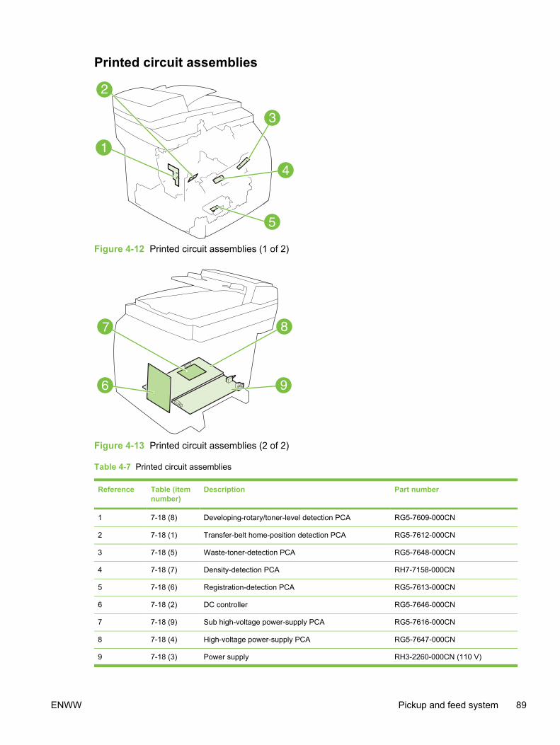
Printed circuit assemblies
Figure 4-12 Printed circuit assemblies (1 of 2)
Figure 4-13 Printed circuit assemblies (2 of 2)
Table 4-7 Printed circuit assemblies
Reference Table (itemnumber)
Description Part number
1 7-18 (8) Developing-rotary/toner-level detection PCA RG5-7609-000CN
2 7-18 (1) Transfer-belt home-position detection PCA RG5-7612-000CN
3 7-18 (5) Waste-toner-detection PCA RG5-7648-000CN
4 7-18 (7) Density-detection PCA RH7-7158-000CN
5 7-18 (6) Registration-detection PCA RG5-7613-000CN
6 7-18 (2) DC controller RG5-7646-000CN
7 7-18 (9) Sub high-voltage power-supply PCA RG5-7616-000CN
8 7-18 (4) High-voltage power-supply PCA RG5-7647-000CN
9 7-18 (3) Power supply RH3-2260-000CN (110 V)
ENWW Pickup and feed system 89

Reference Table (itemnumber)
Description Part number
RH3-2261–000CN (220 V)
Table 4-7 Printed circuit assemblies (continued)
90 Chapter 4 Theory of operation ENWW

Image-formation systemThe image-formation system, which forms a toner image on media, consists of severalinterdependent systems:
■ Electrostatic latent-image-formation system
■ Developing system
■ Transfer block
■ Fuser
■ Transfer belt cleaning block
■ Imaging drum (with ITB)
■ Photosensitive drum
ENWW Image-formation system 91
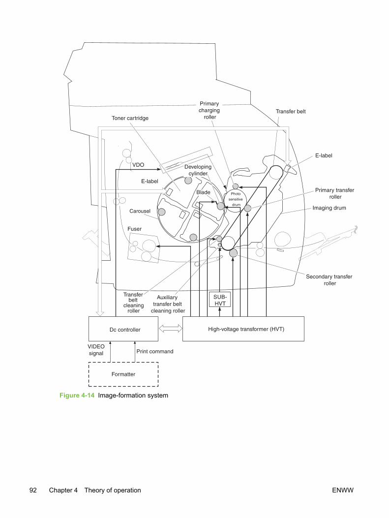
Figure 4-14 Image-formation system
92 Chapter 4 Theory of operation ENWW

Image-formation processLaser printing requires the interaction of several different technologies including electronics, optics,and electrophotographics to produce a printed page. Each process functions independently and mustbe coordinated with the other device processes. Image formation consists of the following fiveprocesses:
1 Latent-image formation
2 Developing
3 Image transfer
4 Fusing
5 Transfer-belt cleaning
The five processes are divided into twelve steps, which are shown in the Image-formation processgraphic and are described in the following sections.
Figure 4-15 Image-formation process
ENWW Image-formation system 93
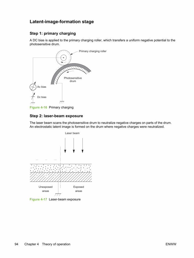
Latent-image-formation stage
Step 1: primary chargingA DC bias is applied to the primary charging roller, which transfers a uniform negative potential to thephotosensitive drum.
Figure 4-16 Primary charging
Step 2: laser-beam exposureThe laser beam scans the photosensitive drum to neutralize negative charges on parts of the drum.An electrostatic latent image is formed on the drum where negative charges were neutralized.
Figure 4-17 Laser-beam exposure
94 Chapter 4 Theory of operation ENWW
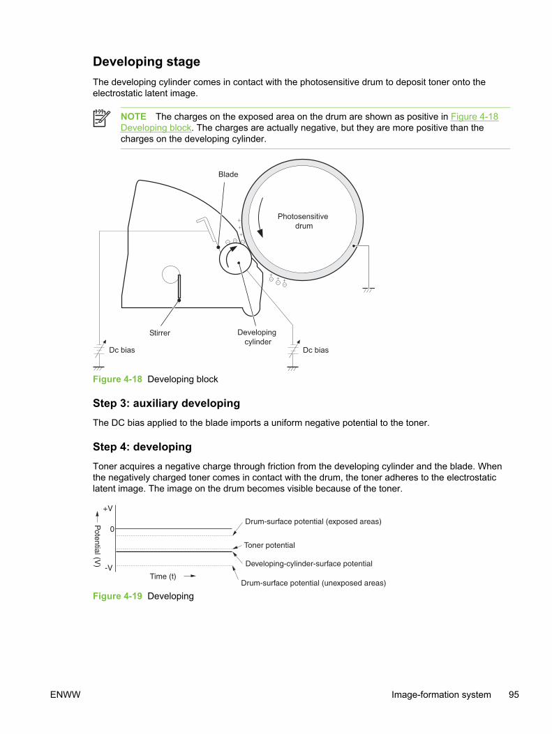
Developing stageThe developing cylinder comes in contact with the photosensitive drum to deposit toner onto theelectrostatic latent image.
NOTE The charges on the exposed area on the drum are shown as positive in Figure 4-18Developing block. The charges are actually negative, but they are more positive than thecharges on the developing cylinder.
Figure 4-18 Developing block
Step 3: auxiliary developingThe DC bias applied to the blade imports a uniform negative potential to the toner.
Step 4: developingToner acquires a negative charge through friction from the developing cylinder and the blade. Whenthe negatively charged toner comes in contact with the drum, the toner adheres to the electrostaticlatent image. The image on the drum becomes visible because of the toner.
Figure 4-19 Developing
ENWW Image-formation system 95

Transfer stage
Step 5: primary transferThe primary transfer roller, to which a DC positive bias is applied, imparts a positive charge on thetransfer belt. The negatively charged toner on the drum is transferred to the positively chargedtransfer belt. This procedure is repeated for each color (yellow, magenta, cyan, and black).
The DC positive bias is increased for each successive color to make sure that all of the colorsadhere to the transfer belt.
Figure 4-20 Primary transfer
Step 6: secondary transferThe secondary transfer roller, to which a DC positive bias is applied, imparts a positive charge to theprint media. When the print media comes in contact with the transfer belt, the toner is transferred tothe print media.
NOTE When secondary transfer is complete, a DC negative bias is applied to the secondarytransfer roller to prevent toner on the transfer belt from adhering to the secondary transferroller.
96 Chapter 4 Theory of operation ENWW
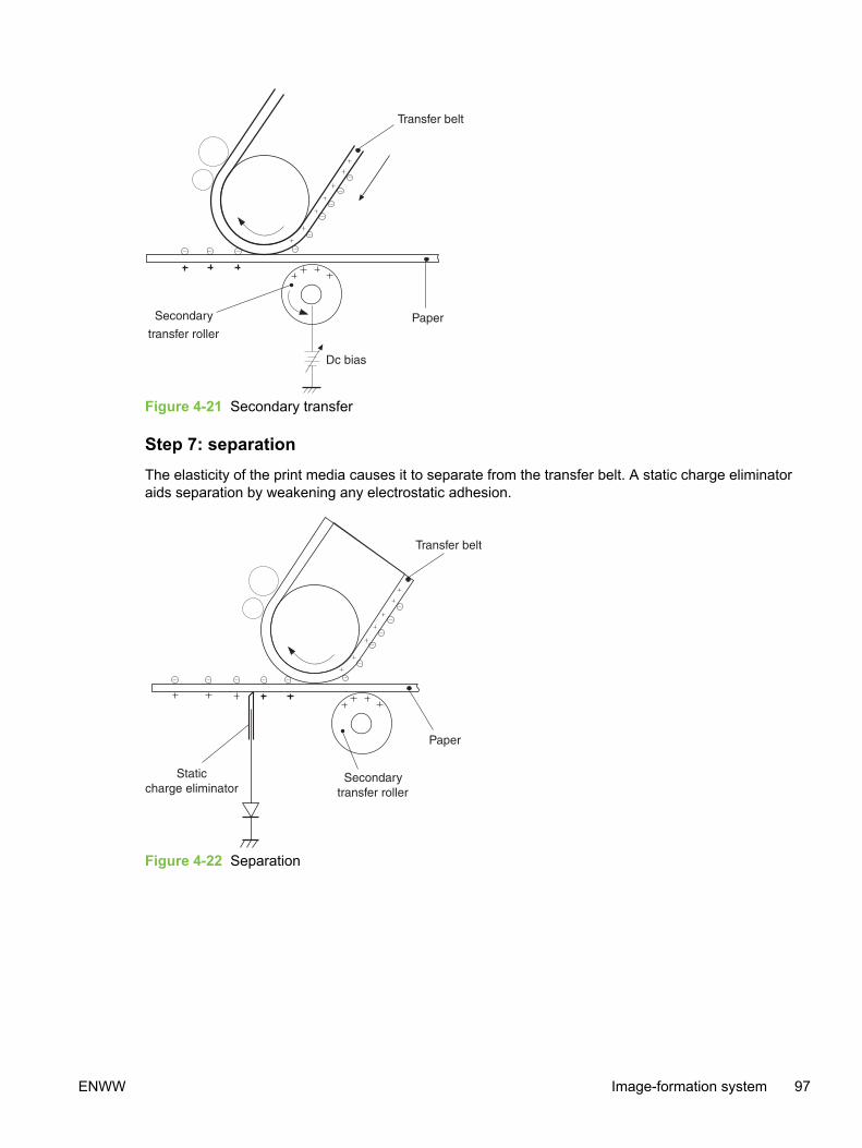
Figure 4-21 Secondary transfer
Step 7: separationThe elasticity of the print media causes it to separate from the transfer belt. A static charge eliminatoraids separation by weakening any electrostatic adhesion.
Figure 4-22 Separation
ENWW Image-formation system 97

Fusing stageThe heat of the fuser bonds the toner to the media.
Step 8: fusingThe DC negative bias applied to the fusing film strengthens the holding force of the toner on the printmedia and prevents the toner from scattering.
Figure 4-23 Fusing
Step 9: roller charging (auxiliary transfer belt cleaning roller)During secondary transfer, not all of the toner on the transfer belt is transferred to the print media.Toner that remains on the belt is called "residual toner."
The auxiliary transfer belt cleaning roller, to which a DC positive bias is applied, imparts a positivecharge to the residual toner, strengthening its hold on the transfer belt. This prevents toner fromfalling off of the transfer belt and scattering in the device.
Figure 4-24 Roller charging (auxiliary transfer belt cleaning roller)
98 Chapter 4 Theory of operation ENWW
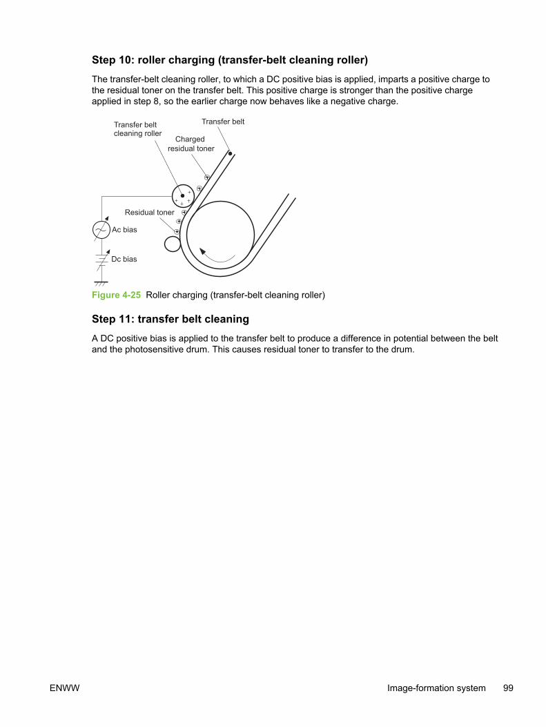
Step 10: roller charging (transfer-belt cleaning roller)The transfer-belt cleaning roller, to which a DC positive bias is applied, imparts a positive charge tothe residual toner on the transfer belt. This positive charge is stronger than the positive chargeapplied in step 8, so the earlier charge now behaves like a negative charge.
Figure 4-25 Roller charging (transfer-belt cleaning roller)
Step 11: transfer belt cleaningA DC positive bias is applied to the transfer belt to produce a difference in potential between the beltand the photosensitive drum. This causes residual toner to transfer to the drum.
ENWW Image-formation system 99
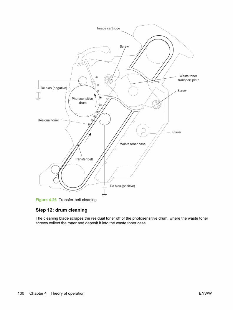
Figure 4-26 Transfer-belt cleaning
Step 12: drum cleaningThe cleaning blade scrapes the residual toner off of the photosensitive drum, where the waste tonerscrews collect the toner and deposit it into the waste toner case.
100 Chapter 4 Theory of operation ENWW

Figure 4-27 Drum cleaning
ENWW Image-formation system 101

Print cartridgeThe device has four print cartridges: yellow, magenta, cyan, and black. Each print cartridge containsa developing cylinder, toner-feed roller, and stirrer. The developer motor rotates these parts so thateach print cartridge can use toner to form a visible image on the drum.
The carousel motor rotates the E-label reader, which communicates E-label information to the DCcontroller.
The developing rotary/toner level detection PCA uses an LED (light emitter) and a photodiode (lightreceiver) to determine the toner level in each print cartridge.
Figure 4-28 Print cartridge
102 Chapter 4 Theory of operation ENWW

Imaging-drum E-labelThe E-label is nonvolatile memory, which is built into the imaging drum and stores usage information.When the imaging drum is installed in the device, the E-label makes constant contact with the E-labelreader. The E-label reader sends memory information to the DC controller, which updates theinformation and sends it back to the E-label.
The DC controller instructs the E-label to read information when:
■ The device is turned on.
■ The top cover is closed.
■ A command is sent from the video controller.
The DC controller instructs the E-label to write information when:
■ A specified period occurs during printing.
■ A command is sent from the video controller.
If the E-label reader fails to read or write information four times in a row, the DC controller notifies thevideo controller that an abnormality exists in the imaging drum.
Figure 4-29 Print-cartridge E-label
ENWW Image-formation system 103
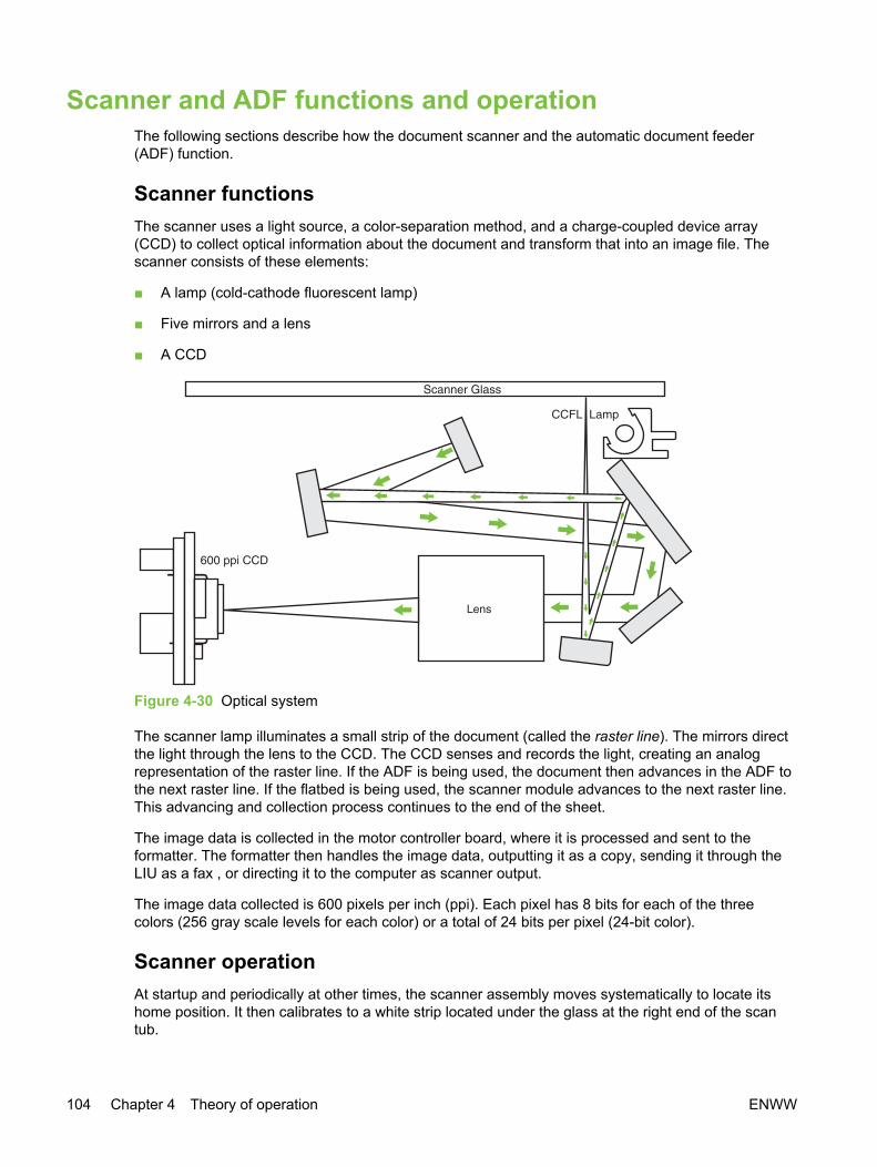
Scanner and ADF functions and operationThe following sections describe how the document scanner and the automatic document feeder(ADF) function.
Scanner functions The scanner uses a light source, a color-separation method, and a charge-coupled device array(CCD) to collect optical information about the document and transform that into an image file. Thescanner consists of these elements:
■ A lamp (cold-cathode fluorescent lamp)
■ Five mirrors and a lens
■ A CCD
Figure 4-30 Optical system
The scanner lamp illuminates a small strip of the document (called the raster line). The mirrors directthe light through the lens to the CCD. The CCD senses and records the light, creating an analogrepresentation of the raster line. If the ADF is being used, the document then advances in the ADF tothe next raster line. If the flatbed is being used, the scanner module advances to the next raster line.This advancing and collection process continues to the end of the sheet.
The image data is collected in the motor controller board, where it is processed and sent to theformatter. The formatter then handles the image data, outputting it as a copy, sending it through theLIU as a fax , or directing it to the computer as scanner output.
The image data collected is 600 pixels per inch (ppi). Each pixel has 8 bits for each of the threecolors (256 gray scale levels for each color) or a total of 24 bits per pixel (24-bit color).
Scanner operationAt startup and periodically at other times, the scanner assembly moves systematically to locate itshome position. It then calibrates to a white strip located under the glass at the right end of the scantub.
104 Chapter 4 Theory of operation ENWW
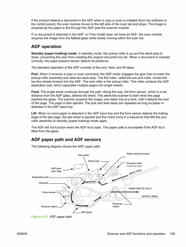
If the product detects a document in the ADF when a copy or scan is initiated (from the software orthe control panel), the scan module moves to the left side of the scan tub and stops. The image isacquired as the paper is fed through the ADF past the scanner module.
If no document is detected in the ADF, or if the model does not have an ADF, the scan moduleacquires the image from the flatbed glass while slowly moving within the scan tub.
ADF operationStandby (paper-loading) mode: In standby mode, the pickup roller is up and the stack-stop isdown, preventing the user from inserting the original document too far. When a document is insertedcorrectly, the paper-present sensor detects its presence.
The standard operation of the ADF consists of the pick, feed, and lift steps.
Pick: When it receives a copy or scan command, the ADF motor engages the gear train to lower thepickup-roller assembly and raise the stack-stop. The first roller, called the pre-pick roller, moves thetop few sheets forward into the ADF. The next roller is the pickup roller. This roller contacts the ADFseparation pad, which separates multiple pages into single sheets.
Feed: The single sheet continues through the path. Along the way, the form sensor, which is a setdistance from the ADF glass, detects the sheet. This alerts the scanner to start when the pagereaches the glass. The scanner acquires the image, one raster line at a time, until it detects the endof the page. The page is then ejected. The pick and feed steps are repeated as long as paper isdetected in the ADF input tray.
Lift: When no more paper is detected in the ADF input tray and the form sensor detects the trailingedge of the last page, the last sheet is ejected and the motor turns in a sequence that lifts the pickroller assembly to standby (paper-loading) mode again.
The ADF will not function when the ADF lid is open. The paper path is incomplete if the ADF lid islifted from the glass.
ADF paper path and ADF sensorsThe following diagram shows the ADF paper path.
PAGE EJECTS FULLY
OUTPUT AREA
ADF glass
Prescan rollers
INPUT TRAY
Form sensor
Postscanrollers
Pre-pick rollerPicks top sheet
Stack stop
Pick rollerPaper present sensor
ADF dooropen flag
Separation pad
Cleanout
Figure 4-31 ADF paper path
ENWW Scanner and ADF functions and operation 105

The paper-present sensor determines if paper is in the ADF. The form sensor detects the top andbottom edges of the document. One other sensor detects an open ADF door.
ADF jam detectionThe ADF has two sensors that detect paper. The paper-present sensor detects the presence ofmedia in the ADF input tray. The form sensor detects media moving through the ADF. If a jam isdetected, the ADF immediately stops the paper feeding and a jam message appears on the control-panel display.
A jam can be detected under any of the following conditions:
■ Document-feeder jam—When documents are detected in the ADF input tray, and a commandto copy, scan or fax is received, the scan module travels to the left side of the scan assemblyand stops beneath the ADF scanner glass. The ADF then attempts three times, or for about tenseconds, to advance the paper to the form sensor. If the paper does not advance, the scanmodule travels back to the home position on the right side of the scanner assembly. Themessage Document feeder mispick. Reload. appears on the control-panel display.
■ Long-document jam—If the paper has advanced to trigger the form sensor, but the trailing edgeis not detected within the time allowed for a 381-mm (15-inch) document (the maximumallowable page length for the ADF), the scanner returns to the home position at the right side ofthe scanner assembly. The message Doc feeder jam. Clear, Reload. appears on the control-panel display.
■ Stall jam—When a page that is less than 381 mm (15 inches) long has advanced to the formsensor but has not left it within the expected time, the paper has probably stalled or jammed. Thescanner returns to the home position at the right side of the scanner assembly. The messageDoc feeder jam. Clear, Reload. appears on the control-panel display.
■ Other—If the paper stops in the ADF and the scan module remains under the ADF scannerglass, an internal firmware error has probably occurred. This is usually remedied by cycling thepower.
106 Chapter 4 Theory of operation ENWW
Fax functions and operationThe following sections describe the fax capabilities of the product.
PSTN operationThe public switched telephone network (PSTN) operates by having a central office (CO) thatgenerates a constant voltage on the TIP and RING wires (48 V, usually). A device goes on-hook byconnecting impedance (such as 600 ohms for the U.S.) across TIP and RING, allowing a line currentto flow. The CO can detect this current and can send impulses like dial tones. The product generatesmore signaling tones, such as dialing digits, to tell the CO how to connect the call. The product canalso detect tones, such as a busy tone from the CO, that tell it how to behave.
When the call is finally connected, the CO behaves as if it were a piece of wire connecting thesender and receiver. This is the period during which all of the fax signaling and data transfer occurs.When a call is completed, the circuit opens again and line current flow ceases, removing the COconnection from both the sender and the receiver.
All of this is done with a two-wire arrangement. The two wires are called TIP and RING on all phonesystems. On most phone systems, the wires appear on pins 3 and 4 of the RJ-11 modular jack (theone on the LIU). These two wires do not have to be polarized because all the equipment works witheither TIP or RING on pin 3 and the other wire on pin 4. This means that cables of either polarity caninterconnect and will still work.
These are the basic functions of PSTN operation that are assumed in the design of the faxsubsystem. The product generates and detects the signaling tones, currents, and data signals thatare required to transmit and receive faxes on the PSTN.
To receive faxes when you hear fax tonesIn general, incoming faxes to the device are automatically received. However, if other devices areconnected to the same phone line, the device may not be set to answer automatically.
If the device is connected to a phone line that receives both fax and phone calls, and you hear faxtones when you answer the extension phone, receive the fax in one of two ways:
■ If you are near the device, press START FAX on the control panel.
■ Press 1-2-3 in sequence on the extension phone keypad, listen for fax transmission sounds, andthen hang up.
NOTE For the 1-2-3 sequence to work, the extension phone setting must be set to On in theFax setup menu.
The fax subsystemThe formatter, LIU, firmware, and software all contribute to the fax functionality. The designs of theformatter and LIU, along with parameters in the firmware, determine the majority of the regulatoryrequirements for telephony on the product.
The fax subsystem is designed to support V.34 fax transmission, lower speeds (such as V.17 fax),and older fax machines.
ENWW Fax functions and operation 107

Formatter in the fax subsystemThe formatter contains the modem chipset (DSP and CODEC) that controls the basic fax functions oftone generation and detection, along with channel control for the fax transmissions.
The CODEC and its associated circuitry act to control transmit and receive gains, and to compensatefor transmission signal coupling into the receive channel. The formatter also contains circuitry thatadds termination impedance to help match the telephone network impedance.
LIU in the fax subsystemTwo versions of the LIU are used in the HP Color LaserJet 2820/2830/2840 all-in-one. One is used inthe North American, South American, and Asian countries/regions. The other is used primarily inEuropean countries/regions.
The following are features that are different in the European version:
■ A different voltage-protection device
■ Current limiting of the DC current
■ Filtering for the countries/regions that use billing or metering tones
■ Control of the impedance of the DC circuit through the SHUNT signal
Because the TIP and RING are not polarized, all LIU circuitry that connects to TIP and RING isbidirectional. The LIU operates identically when TIP and RING are reversed.
Safety isolationThe most important function of the LIU is the safety isolation between the high-voltage, transient-prone environment of the telephone network (TNV [telephone network voltage]) and the low-voltageanalog and digital circuitry of the formatter (SELV [secondary extra-low voltage]). This safetyisolation provides both customer safety and product reliability in the telecom environment.
Any signals that cross the isolation barrier do so either optically or magnetically. The breakdownvoltage rating of barrier-critical components is greater than 1.5 kV.
Safety-protection circuitryIn addition to the safety barrier, the LIU protects against RING and over-current events.
Telephone over-voltages can be either differential mode or common mode. The RING can betransient in nature (a lightning-induced surge or ESD) or continuous (a power line crossed with aphone line). The LIU protection circuitry provides margin against combinations of RING events.
Common mode protection is provided by the selection of high-voltage-barrier critical components(transformer, relay, and optoisolators). The safety barrier of the LIU PCB traces and the clearancebetween the LIU and surrounding components also contribute to common mode protection.
A voltage suppressor (a crowbar-type SIDACTOR) provides differential protection. This devicebecomes low impedance at approximately 300 V differential, and crowbars to a low voltage. A seriesthermal switch works in conjunction with the crowbar for continuous RING events, such as crossedpower lines.
When the differential RING is continuous, the resulting over-current causes the thermal switch tobecome high impedance, disconnecting RING from the network and protecting the crowbar from
108 Chapter 4 Theory of operation ENWW

thermal overload. The thermal switch automatically resets to low impedance after the over-currentcondition is removed, reconnecting RING to the network.
Data pathThe magnetically coupled signals that cross the isolation barrier go either through a transformer or arelay. The TIP and RING signals use a transformer to cross the isolation barrier.
TIP and RING are the two-wire paths for all signals from the telephone network. All signaling anddata information comes across them, including fax tones and fax data.
The telephone network uses DC current to determine the hook state of the telephone, so line currentmust be present during a call. On some line interfaces this current flows through the transformer, buton the LIU, a capacitor blocks the current from going into the transformer.
Blocking the current with a capacitor prevents the core of the transformer from being saturated by thehigh DC voltage, which can affect the AC signal quality. Rather than permitting the current to flowthrough the transformer, this LIU directs the current through another circuit called a gyrator or dc holdcircuit. This creates the path for the central office-current flow when a call is in progress.
Hook stateAnother magnetically coupled signal is the control signal that disconnects the downstream telephonedevices (such as a phone or answering machine). A control signal originating on the formatter canchange the relay state, causing the auxiliary jack (downstream jack) to be disconnected from thecircuit.
The product takes control of calls that it recognizes as fax calls. If the product does not directly pickup the call, it monitors incoming calls for the fax tone or for the user to direct it to receive a fax. Thisidle mode is also called eavesdropping. This mode is active when the product is on-hook but currentexists in the downstream phone line because another device is off-hook. During eavesdropping, thereceive circuit is enabled but has a different gain from the current that is generated during normal faxtransmissions.
The product does not take control of the line unless it detects a fax tone or the operator tells it toconnect manually. This feature allows the user to make voice calls from a phone that is connected tothe product without being cut off if a fax is received.
Downstream current detectionThe aux phone detect signal is optically coupled. This signal tells the firmware that an active phone(or modem or answering machine) is connected to the auxiliary port of the product (the right side ofthe RJ-11 jack).
A circuit that can detect current above a certain threshold generates the downstream-current-detection signal. The downstream current goes through a resistor, generating a voltage. If thisvoltage is above the threshold level, the signal changes state.
The downstream-current-detection signal is coupled back to the formatter through an optoisolatorand across the safety isolation barrier. The firmware uses this signal to ensure that the product doesnot go off-hook (and disconnect a downstream call) until it has been authorized to do so (by amanual fax start or detection of the appropriate tones).
Hook switch controlAnother optically coupled signal is the hook switch control. This signal from the formatter causes anoptoisolator on the LIU to activate (making an open circuit into a short circuit). When shorted, the
ENWW Fax functions and operation 109

circuit is drawing DC current from the central office and is considered “on-hook.” When open, no dccurrent flows and the state is considered to be “off-hook.”
For pulse dialing, the optoisolator is toggled on and off with a particular timing sequence to generatepulses that the central offices of the telephone company recognizes as dialing digits.
Ring detectAnother optically coupled signal on the LIU is ring detect. Ring detect is a combination of voltagelevels and cadence (time on and time off). Both must be present in order for the product to detect avalid ring.
The LIU works with the firmware to determine if an incoming signal is an answerable ring. Whencircuits on the LIU detect a ring voltage above a certain threshold, a corresponding signal is passedto the formatter to indicate that the ring is above the threshold. The firmware then measures theamount of time that the signal is high and low, and qualifies the cadence to determine whether it is avalid ring.
Line current controlThe DC current from the CO needs to have a path to flow from TIP to RING. Because the currentdoes not flow in the transformer, a path through some transistors and diodes (the DC hold circuit)acts like a simulated inductor (thus replacing the function of the transformer). This DC hold circuit isthe main component of the voltage-current characteristic between TIP and RING.
Two other functions of this block of circuits are the current limit and the SHUNT for Europe. Currentlimit basically maintains a constant current from TIP to RING after the voltage reaches about 50 mA.Even if the voltage varies, the current will remain the same.
The SHUNT function changes the impedance (the current-voltage characteristic) during certainspecial events, such as pulse dialing and when the devices goes on-hook.
During such an event, the firmware tells the DSP on the formatter to activate SHUNT. A signal goesto the LIU through an optoisolator (optically coupled), which changes the state of some transistors sothat the board has a linear current characteristic (normally, it is current-limited). Then more currentcan flow to the network, as required by these special events.
Billing (metering) tone filtersSwitzerland and Germany provide high-frequency AC signals on the phone line in order to billcustomers. The LC (inductor, capacitor) notch filters are provided on the European LIUs to preventthese billing signals from adversely affecting the data path and the dc hold circuit.
An additional filter in the cable (for certain countries/regions) can, in some cases, supplement theseLC notch filters. Because these billings signals are not used in the U.S., these filters are not presenton the U.S. LIU.
Fax page storage in flash memoryFax pages are the electronic images of the document page. They can be created in any of threeways: scanned to be sent to another fax machine, generated to be sent by the computer, or receivedfrom a fax machine to be printed.
The product stores all fax pages in flash memory automatically. After these pages are written intoflash memory they are stored until the pages are sent to another fax machine, printed on the product,transmitted to the computer, or erased by the user.
110 Chapter 4 Theory of operation ENWW

These pages are stored in flash memory, which is the nonvolatile memory that can be repeatedlyread from, written to, and erased. The product has 4 MB of flash memory, of which 3.4 MB isavailable for fax storage. The remaining 0.6 MB is used for the file system and reclamation. AddingRAM does not affect the fax page storage because the product does not use RAM for storing faxpages.
Stored fax pagesThe user can reprint stored fax pages in case of errors. The product will re-send stored fax pagesafter a busy signal, comm error, no answer, or a power failure. Other fax devices store fax pages ineither normal RAM or short-term RAM. Normal RAM immediately loses its data when power is lost,while short-term RAM loses its data about 60 minutes after a power failure. Flash memory maintainsits data for years without any applied power.
Advantages of flash memory storage Fax pages stored in flash memory are persistent. They are not lost as a result of a power failure, nomatter how long the power is off. Users can reprint faxes in case the print cartridge runs out of toneror the product experiences other errors while printing faxes.
The product also has scan-ahead functionality that makes use of flash memory. Scan-aheadautomatically scans pages into flash memory before a fax job is sent. This allows the sender to pickup their original document immediately after it is scanned, eliminating the need to wait until the fax istransmission is complete.
Because fax pages are stored in flash memory, not RAM, more RAM is available to handle largerand more complicated copy and print jobs.
ENWW Fax functions and operation 111

112 Chapter 4 Theory of operation ENWW

5 Removal and replacement
Chapter contents● Removal and replacement strategy
● User-replaceable parts
● Covers
● Main assemblies
● Motors and fans
● Printed circuit assemblies (PCAs)
● Trays
ENWW Chapter contents 113

Removal and replacement strategy Replace parts in the reverse order of their removal. Directions for difficult or critical replacementprocedures are included.
WARNING! The sheet-metal edges of the device can be sharp. Use caution when workingon the device.
NOTE Note the length, diameter, color, type, and location of each screw. Be sure to returneach screw to its original location during reassembly.
Incorrectly routed or loose wire harnesses can interfere with other internal components andcan become damaged or broken. Frayed or pinched harness wires can be difficult to locate.When replacing wire harnesses, always use the provided wire loops, lance points, or wire-harness guides.
Required toolsThe following tools are needed to service this product:
■ Number 2 Phillips screwdriver with magnetic tip
■ Small flatblade screwdriver
■ Small needle-nose pliers
■ Number 8 torx screwdriver with magnetic tip
■ Number 10 torx screwdriver with magnetic tip
■ Lint-free cloth.
■ ESD mat
■ Penlight
■ Multimeter
CAUTION A PoziDriv screwdriver will damage screw heads on the product. Use a #2Phillips screwdriver.
If you use a multispeed screwdriver, use a torque limiter.
ScrewsThe HP Color LaserJet 2820/2830/2840 all-in-one has four common fasteners. See Table 5-1Common screws for a description of these screw types.
Table 5-1 Common screws
Example Description
Screw, machine, truss head
114 Chapter 5 Removal and replacement ENWW

Example Description
Screw, star
Screw, self-tapping
Screw, torx
The device includes the screws listed in Table 5-2 Screws for the HP Color LaserJet 2820/2830/2840all-in-one.
Table 5-2 Screws for the HP Color LaserJet 2820/2830/2840 all-in-one
Description Part number
Screw, with washer, M3x6 XB2-4300-605
Screw, RS, M3x6 XA9-0849-000
XA9-1495-010
Screw, RS, M3x8 XA9-1291-000
XA9-1449-000
XA9-1500-000
Screw, S, M3x8 XA9-1500-000
XA9-1500-010
Screw, tap, truss head, M4x10 XB4-7401-005
Screw, TP, M3x6 XA9-0267-000
Screw, with washer, M4x12 XA9–1422–000
Screw, P, M3x8 XB4–5300–809
Screw, Binding, M3x8 XA9–1472–000
Screw, TP, M3x4 XB6–7300–407
Electrostatic discharge
CAUTION The product contains parts that are sensitive to electrostatic discharge (ESD).Always service the product at an ESD-protected workstation, or use an ESD mat.
Watch for the ESD symbol (shown at left) to identify the parts that are sensitive to ESD. Protectthese parts by using an ESD wrist strap and by placing ESD-sensitive parts into protective ESDpouches.
Table 5-1 Common screws (continued)
ENWW Removal and replacement strategy 115

Before performing serviceFollow the pre-service procedures before you perform service.
1 Remove all media from the product.
2 Place the product on an ESD mat. If an ESD mat or an ESD-protected workstation is notavailable, discharge body static and ground the product chassis before servicing the product.
3 If possible, print a Configuration page to record critical customer data, such as a network IPaddress, device name, copy counts, and machine fault codes. If you cannot print a Configurationpage, record the data manually, either from HP Toolbox or the device control panel.
4 Remove the imaging drum (see Replacing the imaging drum).
5 Remove the print cartridges (see Replacing the print cartridges).
6 Turn off the device.
7 Unplug the power cord and the interface cable.
After performing serviceAfter performing service on the device, complete the following steps:
1 Replace the print cartridges and imaging drum.
2 Reload the input tray with media.
3 Perform the necessary post-service tests in the next section.
Post-service testsOnce service has been completed, the following tests can be used to verify that the repair orreplacement was successful.
Test 1 (print-quality test)1 Verify that you have completed the necessary reassembly steps.
2 Ensure that the input tray contains clean, unmarked paper.
3 Attach the power cord and interface cable, and then turn on the device.
4 Verify that the expected start-up sounds occur.
5 Perform a control-panel test from the secondary service menu (see Secondary service menu).Verify that the control-panel buttons beep when they are pressed.
NOTE If the control-panel buttons do not beep, verify that the user did not disable thisfunction on the device control panel.
116 Chapter 5 Removal and replacement ENWW
6 Print a Configuration page, and then verify that the expected printing sounds occur.
7 Print a Demo page, and then verify that the print quality is as expected.
8 Send a print job from the host computer, and then verify that the output meets expectations.
9 If necessary, restore any customer device settings.
10 Clean the outside of the device with a damp cloth.
Test 2 (copy-quality test)1 Verify that you have completed the necessary reassembly steps.
2 Ensure that the input tray contains clean, unmarked paper.
3 Attach the power cord and interface cable, and then turn on the device.
4 Verify that the expected start-up sounds occur.
5 Print a Configuration page, and then verify that the expected printing sounds occur.
6 Place the Configuration page in the automatic document feeder (ADF).
7 Print a color copy job, and then verify the results.
8 Place the Configuration page on the scanner glass.
9 Print a color copy job, and then verify the results.
10 Clean the outside of the device with a damp cloth.
Test 3 (fax-quality test)
NOTE This test applies to the HP Color LaserJet 2830 all-in-one and HP Color LaserJet2840 all-in-one only
1 Place the Configuration page in the ADF.
2 Enter a valid fax number and send the fax job.
3 Verify that the send quality and receive quality meet expectations.
Test 4 (memory-card test)
NOTE This test applies to the HP Color LaserJet 2840 all-in-one only
1 Insert a memory card into the correct device memory-card slot.
2 Create a proof sheet, and then print an image from the proof sheet (see the device user guide).
3 Verify that the printed image quality meets expectations.
ENWW Removal and replacement strategy 117

Parts removal orderUse the following diagram to determine which parts must be removed before removing other parts.
Figure 5-1 Parts removal order
118 Chapter 5 Removal and replacement ENWW
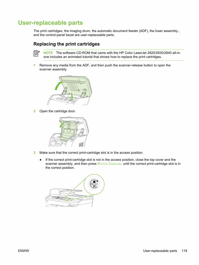
User-replaceable partsThe print cartridges, the imaging drum, the automatic document feeder (ADF), the fuser assembly ,and the control-panel bezel are user-replaceable parts.
Replacing the print cartridges
NOTE The software CD-ROM that came with the HP Color LaserJet 2820/2830/2840 all-in-one includes an animated tutorial that shows how to replace the print cartridges.
1 Remove any media from the ADF, and then push the scanner-release button to open thescanner assembly.
2 Open the cartridge door.
3 Make sure that the correct print-cartridge slot is in the access position.
● If the correct print-cartridge slot is not in the access position, close the top cover and thescanner assembly, and then press ROTATE CAROUSEL until the correct print-cartridge slot is inthe correct position.
ENWW User-replaceable parts 119

4 Pinch together the two large blue tabs on the first cartridge, and then lift the cartridge straight upto remove it from the carousel.
5 Remove the new print cartridge from its packaging, remove the orange cover from the printcartridge, and then pull the orange tab straight out to remove the sealing tape.
6 Squeeze the blue release levers on the print cartridge, holding it with the roller facing you. Lowerthe cartridge straight down into the carousel until it is firmly in place.
● If you need to replace another cartridge, close the top cover and the scanner assembly,press ROTATE CAROUSEL, and then repeat steps 4 through 6.
NOTE If you have replaced a black print cartridge, the device prompts you to run acleaning page, unless the device page count is less than 100 pages.
7 Close the top cover, and then close the scanner assembly.
8 Run a print-quality test (see Test 1 (print-quality test)).
120 Chapter 5 Removal and replacement ENWW

Replacing the imaging drum
NOTE The software CD-ROM that came with the HP Color LaserJet 2820/2830/2840 all-in-one includes an animated tutorial that shows how to replace the imaging drum.
1 Remove any media from the ADF, and then push the scanner-release button to open thescanner assembly.
2 Open the cartridge door.
3 Grasp the imaging drum handle, and then rotate the drum until the handle is at the top.
4 Lift the imaging drum straight up to remove it from the device.
5 Remove the new imaging drum from its packaging.
ENWW User-replaceable parts 121

6 Place the imaging drum on a firm surface, and then pull the orange rings to remove the shippingpins.
7 Remove the orange shipping lock on each end of the imaging drum, and remove the two orangeshipping spacers.
8 Remove the orange cover from the imaging drum.
CAUTION Do not touch the surface of the roller or expose the roller to light for anextended period of time. Doing so could cause print-quality issues.
9 Align the arrows on the side of the imaging drum with the arrows inside the printer.
122 Chapter 5 Removal and replacement ENWW

10 Lower the imaging drum into the printer, and then press it firmlyinto place.
11 Close the top cover and the scanner assembly.
12 Run a print-quality test (see Test 1 (print-quality test)).
Replacing the ADF1 Turn off the device, and then open the ADF.
Figure 5-2 Replace the ADF (1 of 6 )
2 Disconnect the ADF connector by squeezing the tabs together and lifting upward.
Figure 5-3 Replace the ADF (2 of 6 )
3 Remove the ADF by lifting it upward and tilting it forward as the hinges nearly disconnect fromthe device.
Figure 5-4 Replace the ADF (3 of 6 )
ENWW User-replaceable parts 123

4 On the new ADF, unfold the hinges.
Figure 5-5 Replace the ADF (4 of 6 )
5 Insert the hinges on the new ADF so that they are slightly tilted forward, and then push straightdown into the device.
Figure 5-6 Replace the ADF (5 of 6 )
6 Insert the connector by pushing down on it until it clicks into place.
Figure 5-7 Replace the ADF (6 of 6 )
7 Run a copy-quality test (see Test 2 (copy-quality test)).
Replacing the ADF pickup-roller assembly If the ADF has trouble picking paper, the ADF pickup-roller assembly might need to be replaced.
124 Chapter 5 Removal and replacement ENWW
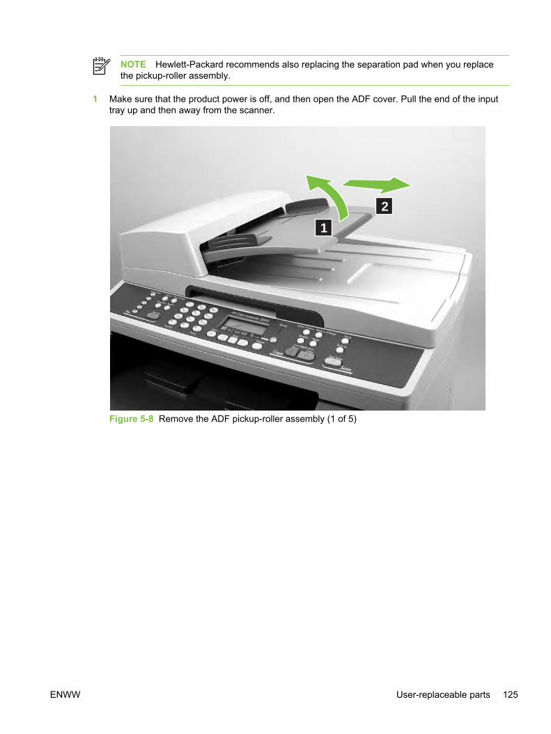
NOTE Hewlett-Packard recommends also replacing the separation pad when you replacethe pickup-roller assembly.
1 Make sure that the product power is off, and then open the ADF cover. Pull the end of the inputtray up and then away from the scanner.
1
2
Figure 5-8 Remove the ADF pickup-roller assembly (1 of 5)
ENWW User-replaceable parts 125

2 Press the round, green button (callout 1) while lifting the green lever (callout 2). Rotate the greenlever until it stops in the open position. The pickup-roller assembly will remain on the blacksurface.
1
2
Figure 5-9 Remove the ADF pickup-roller assembly (2 of 5)
126 Chapter 5 Removal and replacement ENWW

3 Remove the pickup-roller assembly, and put the replacement assembly (callout 3) in exactly thesame place. The largest roller goes in back, and the gear side faces toward the back of theproduct.
3
Figure 5-10 Remove the ADF pickup-roller assembly (3 of 5)
ENWW User-replaceable parts 127

4 Lower the green lever until the flat, green part fits between the rollers. Press down on the pickuproller frame until the assembly snaps into place.
Figure 5-11 Remove the ADF pickup-roller assembly (4 of 5)
128 Chapter 5 Removal and replacement ENWW
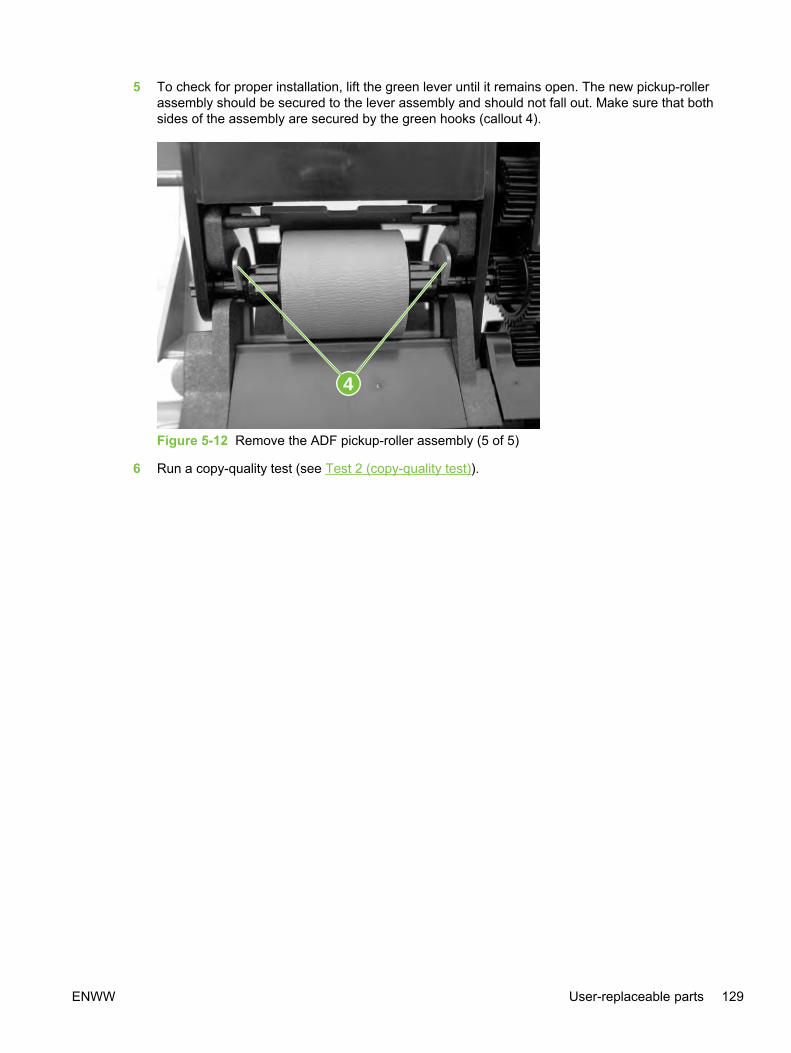
5 To check for proper installation, lift the green lever until it remains open. The new pickup-rollerassembly should be secured to the lever assembly and should not fall out. Make sure that bothsides of the assembly are secured by the green hooks (callout 4).
4
Figure 5-12 Remove the ADF pickup-roller assembly (5 of 5)
6 Run a copy-quality test (see Test 2 (copy-quality test)).
ENWW User-replaceable parts 129

Removing the ADF separation pad
NOTE Hewlett-Packard recommends also replacing the pickup-roller assembly when youreplace the separation pad .
1 Open the ADF door. Use the green lever to raise the pickup-roller assembly.
Figure 5-13 Remove the ADF separation pad (1 of 2)
130 Chapter 5 Removal and replacement ENWW
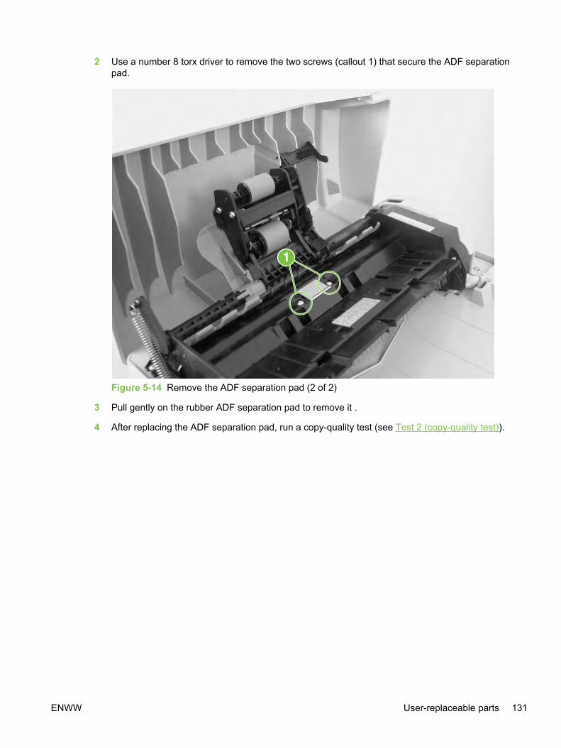
2 Use a number 8 torx driver to remove the two screws (callout 1) that secure the ADF separationpad.
Figure 5-14 Remove the ADF separation pad (2 of 2)
3 Pull gently on the rubber ADF separation pad to remove it .
4 After replacing the ADF separation pad, run a copy-quality test (see Test 2 (copy-quality test)).
ENWW User-replaceable parts 131

Replacing the ADF scanner glass
CAUTION To avoid contamination from dust or other particulates, wipe off dust from theADF scanner glass and the frame before removing the glass.
Remove the ADF scanning glass in a clean, dust-free area.
Do not keep the ADF scanner glass open any longer than necessary.
1 Remove the number 10 torx screw (callout 1), lift out the plastic ADF scanner-glass frame, andthen lift out the glass.
1
Figure 5-15 Remove the ADF scanner glass
132 Chapter 5 Removal and replacement ENWW

2 Replace the glass first, and then install the frame. Make sure the lock mechanism is in thereleased position. Press down on the frame and glass until the lock mechanism snaps back intothe locked position, as shown in Figure 5-16 Install the ADF scanner glass.
Figure 5-16 Install the ADF scanner glass
CAUTION Avoid touching the flatbed glass or the ADF separation pad. Skin oils andfingerprints can contaminate the glass or pad and cause print-quality problems or paper-pickup problems.
3 Replace the torx screw to secure the glass.
Replacing the fuser assembly1 Turn off the device, and then disconnect the power cable.
2 Rotate the locks on the fuser assembly to the unlocked position.
ENWW User-replaceable parts 133

3 Grasp the fuser handle and pull the fuser assembly from the device.
CAUTION The parts on the internal surface of the fuser assembly are very hot. To avoidburning yourself, do not touch those parts.
4 Insert the new fuser assembly into the device.
5 Rotate the locks on the fuser assembly to the locked position.
6 Reconnect the power cable, and then turn on the device.
7 Run a copy-quality test (see Test 2 (copy-quality test)).
Replacing the control-panel bezel1 Turn off the device, and then open the ADF.
2 Remove the control-panel bezel by using your fingers to lift up on the top-center edge of thebezel until it begins to disengage.
Figure 5-17 Replace the control-panel bezel (1 of 3)
134 Chapter 5 Removal and replacement ENWW
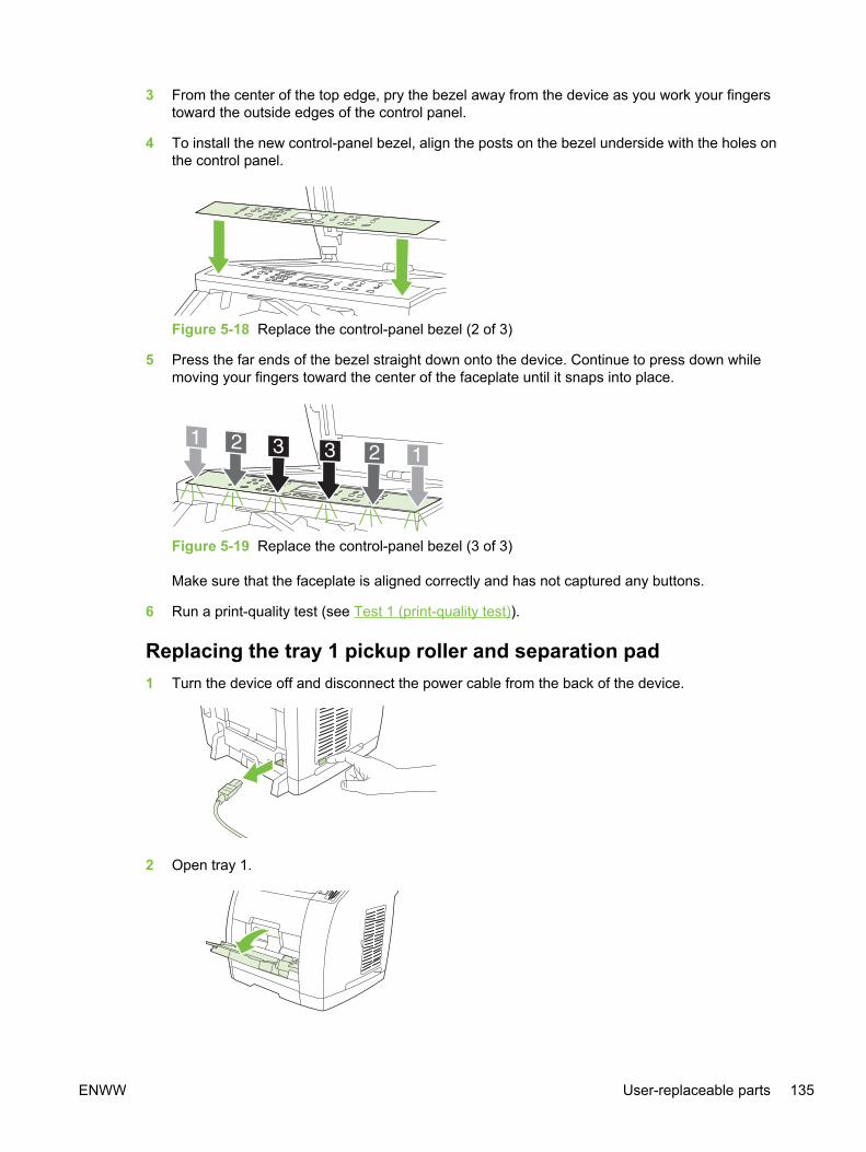
3 From the center of the top edge, pry the bezel away from the device as you work your fingerstoward the outside edges of the control panel.
4 To install the new control-panel bezel, align the posts on the bezel underside with the holes onthe control panel.
Figure 5-18 Replace the control-panel bezel (2 of 3)
5 Press the far ends of the bezel straight down onto the device. Continue to press down whilemoving your fingers toward the center of the faceplate until it snaps into place.
Figure 5-19 Replace the control-panel bezel (3 of 3)
Make sure that the faceplate is aligned correctly and has not captured any buttons.
6 Run a print-quality test (see Test 1 (print-quality test)).
Replacing the tray 1 pickup roller and separation pad1 Turn the device off and disconnect the power cable from the back of the device.
2 Open tray 1.
ENWW User-replaceable parts 135

3 Find the multipurpose roller cover that is located beneath the pickup roller in tray 1.
4 Grasp both sides of the center tab and pull the cover out of the device.
5 Squeeze the tab on the idler roller that is located on the right side of the pickup roller. If the tab isnot visible, rotate the idler roller so that the tab is toward the front of the device.
136 Chapter 5 Removal and replacement ENWW

6 Slide the idler roller to the right to separate it from the pickup roller.
7 Squeeze the tab on the idler roller that is located on the left side of the pickup roller. If the tab isnot visible, rotate the idler roller so that the tab is toward the front of the device.
8 Slide the idler roller to the left to separate it from the pickup roller.
ENWW User-replaceable parts 137

9 Press and hold the button that is located on the right side of the pickup roller. Slide the pickuproller slightly to the right, and then pull it off of the shaft.
10 Move the remaining roller cam to the right so that it no longer sits above the separation pad.
Moving the roller cam will reveal a pin in the roller shaft. Do not remove the pin.
11 Locate the separation pad beneath the area of the shaft from which the pickup roller wasremoved.
138 Chapter 5 Removal and replacement ENWW
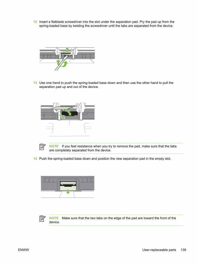
12 Insert a flatblade screwdriver into the slot under the separation pad. Pry the pad up from thespring-loaded base by twisting the screwdriver until the tabs are separated from the device.
13 Use one hand to push the spring-loaded base down and then use the other hand to pull theseparation pad up and out of the device.
NOTE If you feel resistance when you try to remove the pad, make sure that the tabsare completely separated from the device.
14 Push the spring-loaded base down and position the new separation pad in the empty slot.
NOTE Make sure that the two tabs on the edge of the pad are toward the front of thedevice.
ENWW User-replaceable parts 139

15 Snap both sides of the separation pad firmly into place until they click.
CAUTION If the pad is not straight, or if space exists between the pad and the base,make sure that the tabs on the pad are toward the front of the device.
16 Hold down the new separation pad, and slide the roller cam back to the left until it snaps in placewith the pin. Position the new pickup roller so that the button is on the right side, and the openside of the roller faces down. Make sure that the small ridge on the open side of the roller alignswith the groove in the shaft.
17 Slide the left and right idler rollers inward, against the pickup roller, until the idler rollers click intoplace.
140 Chapter 5 Removal and replacement ENWW

18 Hold the faceplate cover as shown in the illustration, and align the cover with the rails on theinside of the device.
19 Grasp both sides of the center tab and insert the cover into the device until the cover clicks intoplace. Close tray 1.
20 Reconnect the power cable to the device, and then turn on the device.
21 Run a print-quality test (see Test 1 (print-quality test)).
ENWW User-replaceable parts 141
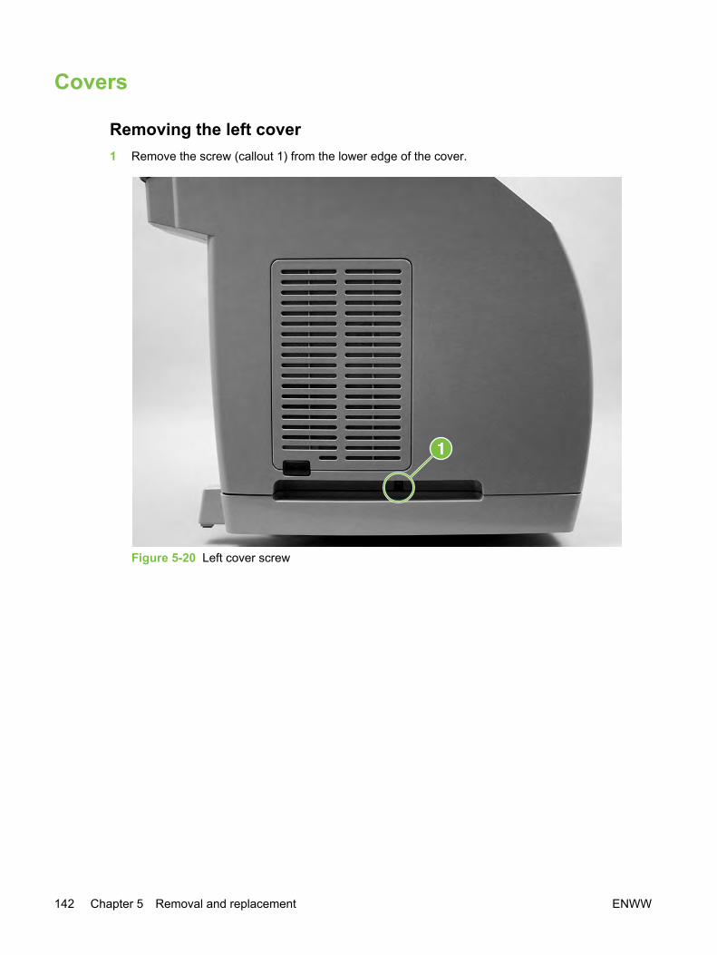
Covers
Removing the left cover1 Remove the screw (callout 1) from the lower edge of the cover.
Figure 5-20 Left cover screw
142 Chapter 5 Removal and replacement ENWW

2 Open top cover, and then disengage the latch at the front of the left cover by prying it away fromthe front.
Figure 5-21 Disengage the left cover latch
ENWW Covers 143
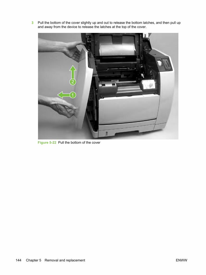
3 Pull the bottom of the cover slightly up and out to release the bottom latches, and then pull upand away from the device to release the latches at the top of the cover.
Figure 5-22 Pull the bottom of the cover
144 Chapter 5 Removal and replacement ENWW

Removing the right cover1 Remove the two screws (callout 1) from the lower edge of the cover.
Figure 5-23 Remove the right-side cover (1 of 2)
ENWW Covers 145

2 Open the scanning assembly, grasp the cover by the handle and by the top, and then pull thebottom of the cover and then up gently, rotating the cover away from the device as you lift it.
Figure 5-24 Remove the right-side cover (2 of 2)
Reinstallation tip When reinstalling the cover, reattach the tab that is closer to the backof the device before reattaching the front.
Removing the right rear cover1 Remove the right cover (see Removing the right cover).
146 Chapter 5 Removal and replacement ENWW

2 On the right rear cover, use a small flatblade screwdriver to disengage the latch at the rear of thecover.
Figure 5-25 Remove the right rear cover (1 of 2)
ENWW Covers 147
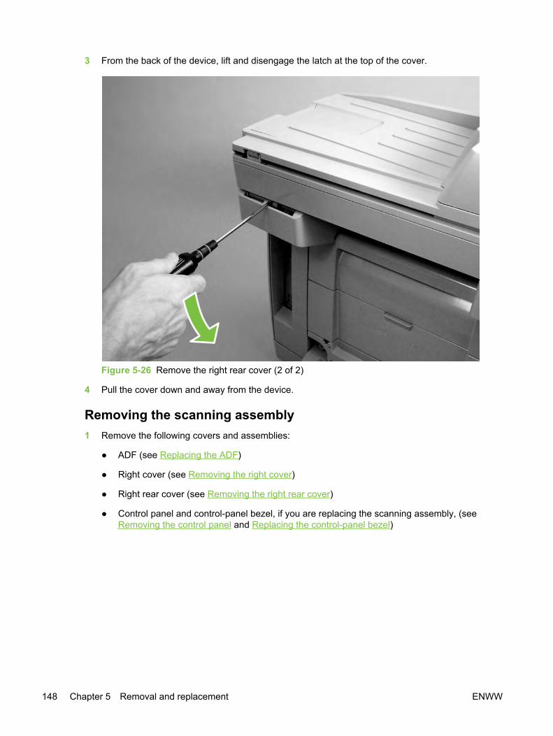
3 From the back of the device, lift and disengage the latch at the top of the cover.
Figure 5-26 Remove the right rear cover (2 of 2)
4 Pull the cover down and away from the device.
Removing the scanning assembly1 Remove the following covers and assemblies:
● ADF (see Replacing the ADF)
● Right cover (see Removing the right cover)
● Right rear cover (see Removing the right rear cover)
● Control panel and control-panel bezel, if you are replacing the scanning assembly, (seeRemoving the control panel and Replacing the control-panel bezel)
148 Chapter 5 Removal and replacement ENWW

2 On the right side of the device, disconnect the four scanner assembly cables (callout 1) at the topof the formatter cage, and then unroute the cables from the device chassis so that they hang atthe back of the device.
Figure 5-27 Remove the scanning assembly from the device (1 of 4)
NOTE Note the order of the cables (long narrow flat cable, short wide flat cable, andthen the wire bundles), and then reroute the cables in the same order when reinstallingthe scanning assembly.
ENWW Covers 149
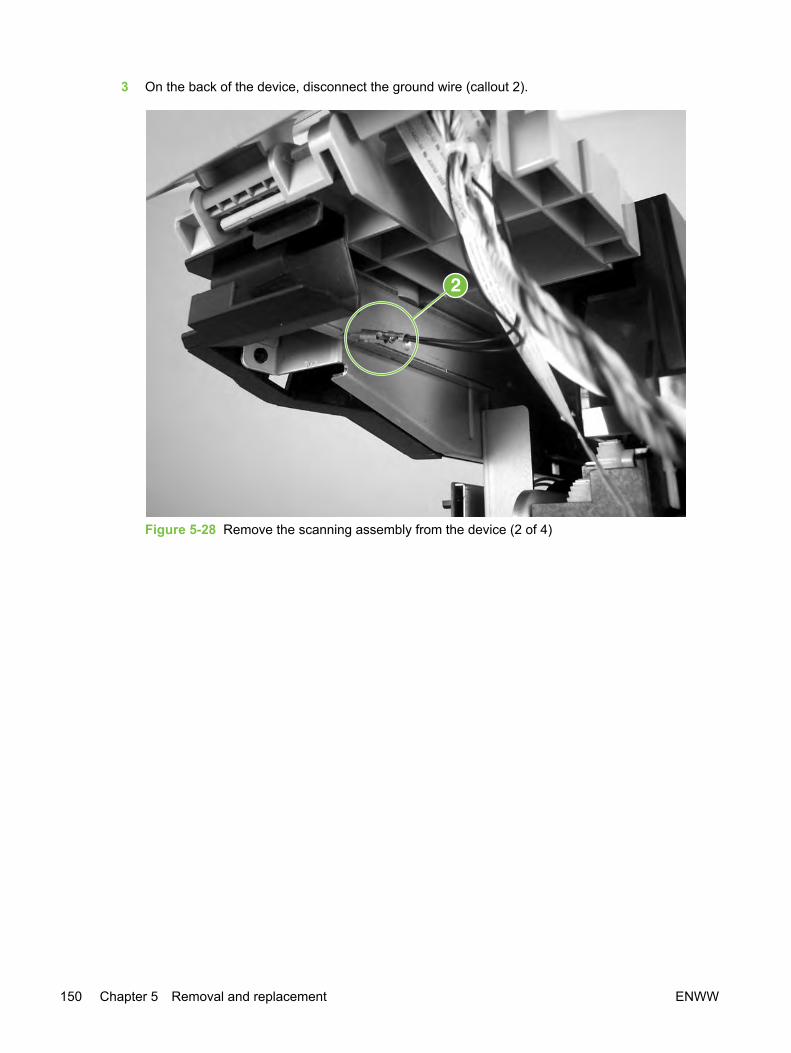
3 On the back of the device, disconnect the ground wire (callout 2).
Figure 5-28 Remove the scanning assembly from the device (2 of 4)
150 Chapter 5 Removal and replacement ENWW
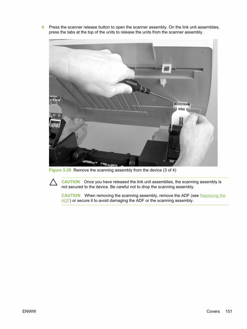
4 Press the scanner release button to open the scanner assembly. On the link unit assemblies,press the tabs at the top of the units to release the units from the scanner assembly.
Figure 5-29 Remove the scanning assembly from the device (3 of 4)
CAUTION Once you have released the link unit assemblies, the scanning assembly isnot secured to the device. Be careful not to drop the scanning assembly.
CAUTION When removing the scanning assembly, remove the ADF (see Replacing theADF) or secure it to avoid damaging the ADF or the scanning assembly.
ENWW Covers 151
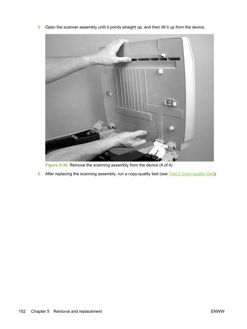
5 Open the scanner assembly until it points straight up, and then lift it up from the device.
Figure 5-30 Remove the scanning assembly from the device (4 of 4)
6 After replacing the scanning assembly, run a copy-quality test (see Test 2 (copy-quality test)).
152 Chapter 5 Removal and replacement ENWW

Removing the left rear cover1 Remove the left cover (see Removing the left cover).
2 On the left rear cover, use a flatblade screwdriver to disengage the latch indicated by the arrow(callout 1) on the cover by pushing the screwdriver in the direction indicated by the arrow.
Figure 5-31 Remove the left rear cover
3 From the back of the device, pull the cover away from the device.
Removing the left upper cover1 Remove the left cover (see Removing the left cover).
2 Open the scanner assembly, and then open the cartridge cover in the top cover assembly.
ENWW Covers 153
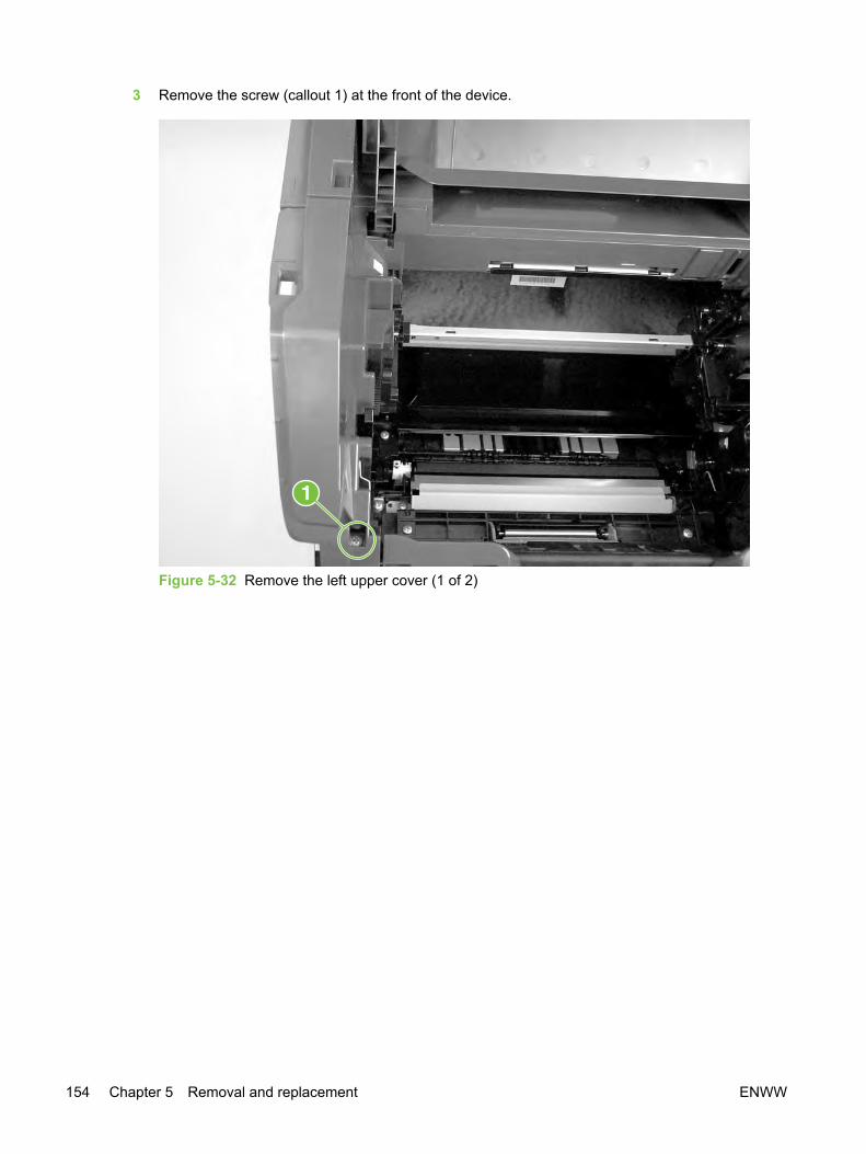
3 Remove the screw (callout 1) at the front of the device.
Figure 5-32 Remove the left upper cover (1 of 2)
154 Chapter 5 Removal and replacement ENWW

4 Grasp the front of the cover, and then pull up and toward the rear to disengage the latches at thetop rear of the cover.
Figure 5-33 Remove the left upper cover (2 of 2)
Removing the right upper cover1 Remove the right cover (see Removing the right cover).
2 HP Color LaserJet 2840 all-in-one only: Detach the memory-card reader cable and the twogrounding wires. See Replacing the memory-card assembly (HP Color LaserJet 2840 all-in-oneonly).
3 Open the scanner assembly, and then open the cartridge cover in the top cover assembly.
ENWW Covers 155

4 Remove two screws (callout 1) from the cover.
Figure 5-34 Remove the right upper cover (1 of 2)
156 Chapter 5 Removal and replacement ENWW
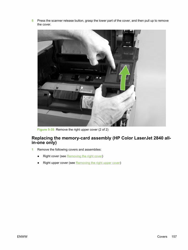
5 Press the scanner release button, grasp the lower part of the cover, and then pull up to removethe cover.
Figure 5-35 Remove the right upper cover (2 of 2)
Replacing the memory-card assembly (HP Color LaserJet 2840 all-in-one only)1 Remove the following covers and assemblies:
● Right cover (see Removing the right cover)
● Right upper cover (see Removing the right upper cover)
ENWW Covers 157
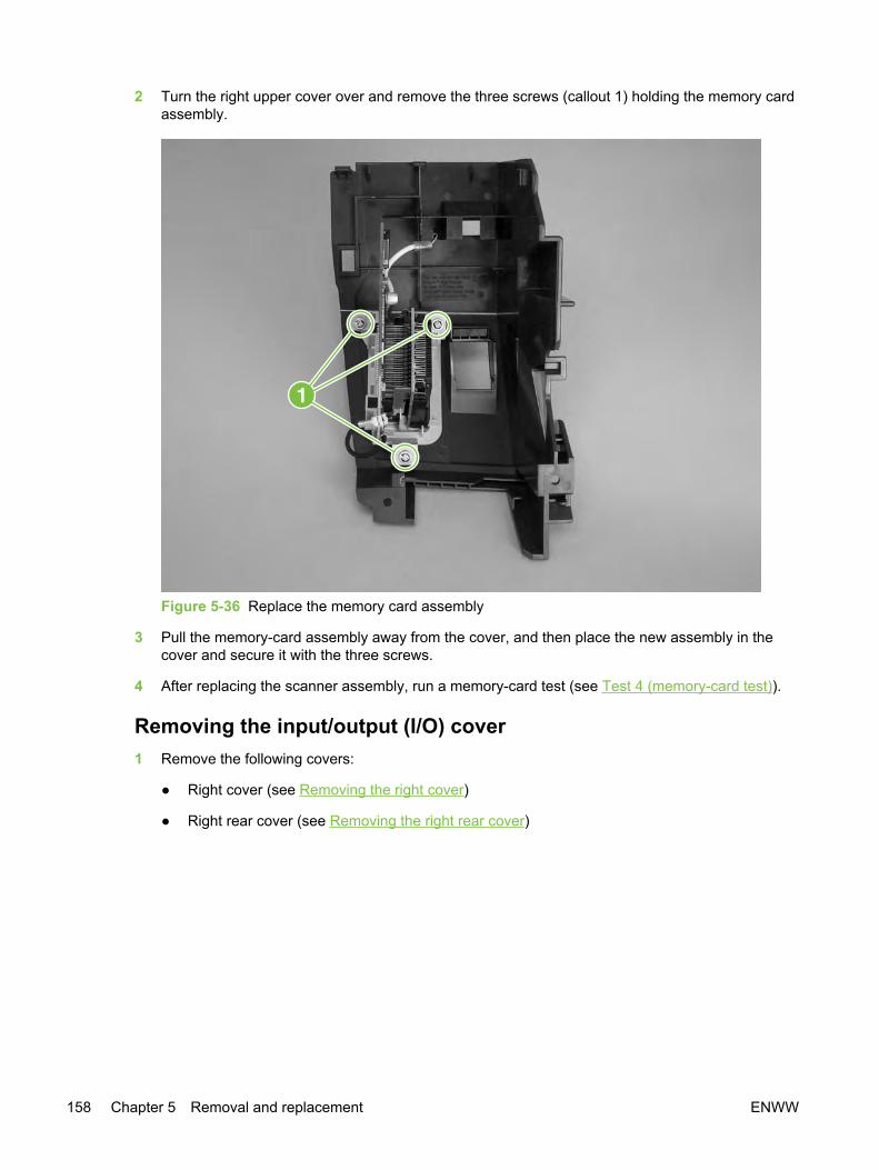
2 Turn the right upper cover over and remove the three screws (callout 1) holding the memory cardassembly.
Figure 5-36 Replace the memory card assembly
3 Pull the memory-card assembly away from the cover, and then place the new assembly in thecover and secure it with the three screws.
4 After replacing the scanner assembly, run a memory-card test (see Test 4 (memory-card test)).
Removing the input/output (I/O) cover1 Remove the following covers:
● Right cover (see Removing the right cover)
● Right rear cover (see Removing the right rear cover)
158 Chapter 5 Removal and replacement ENWW
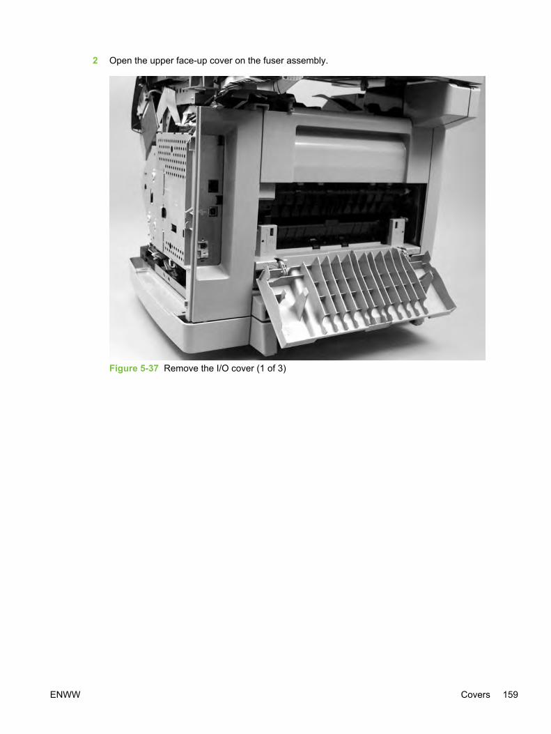
2 Open the upper face-up cover on the fuser assembly.
Figure 5-37 Remove the I/O cover (1 of 3)
ENWW Covers 159
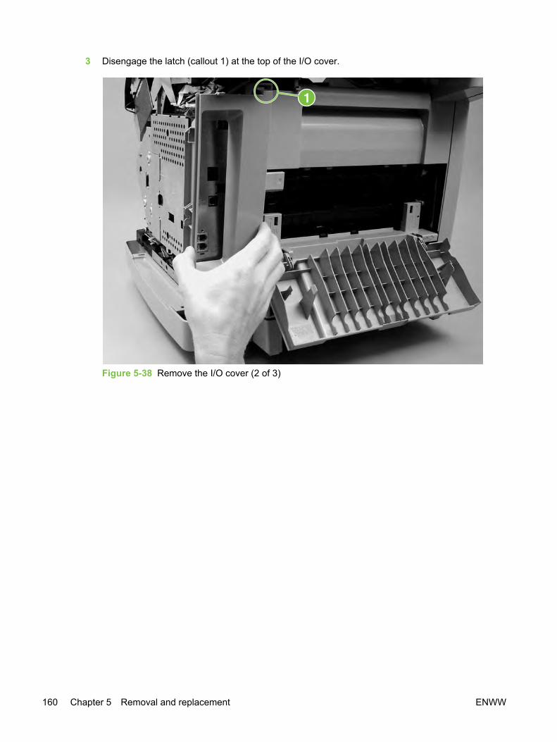
3 Disengage the latch (callout 1) at the top of the I/O cover.
Figure 5-38 Remove the I/O cover (2 of 3)
160 Chapter 5 Removal and replacement ENWW

4 Pull the top of the I/O cover away from the device to disengage the latches (callout 2) at thebottom of the cover.
Figure 5-39 Remove the I/O cover (3 of 3)
Removing the back cover1 Remove the following covers
● Left cover (see Removing the left cover)
● Right cover (see Removing the right cover)
● Left rear cover (see Removing the left rear cover)
● Right rear cover (see Removing the right rear cover)
● I/O cover (see Removing the input/output (I/O) cover)
Leave the upper face-up cover on the fuser assembly open.
ENWW Covers 161

2 Disengage the two latches (callout 1) at the top of the cover.
Figure 5-40 Remove the back cover
3 Pull the top of the cover down and away from the device to release the latches at the bottom ofthe cover.
Removing the top cover assembly1 Remove the following covers and assembly:
● Left cover (see Removing the left cover)
● Right cover (see Removing the right cover)
● Left upper cover (see Removing the left upper cover)
● Right upper cover (see Removing the right upper cover)
● Left rear cover (see Removing the left rear cover)
● Right rear cover (see Removing the right rear cover)
162 Chapter 5 Removal and replacement ENWW
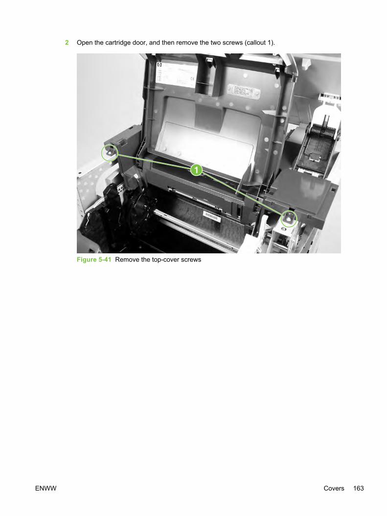
2 Open the cartridge door, and then remove the two screws (callout 1).
Figure 5-41 Remove the top-cover screws
ENWW Covers 163
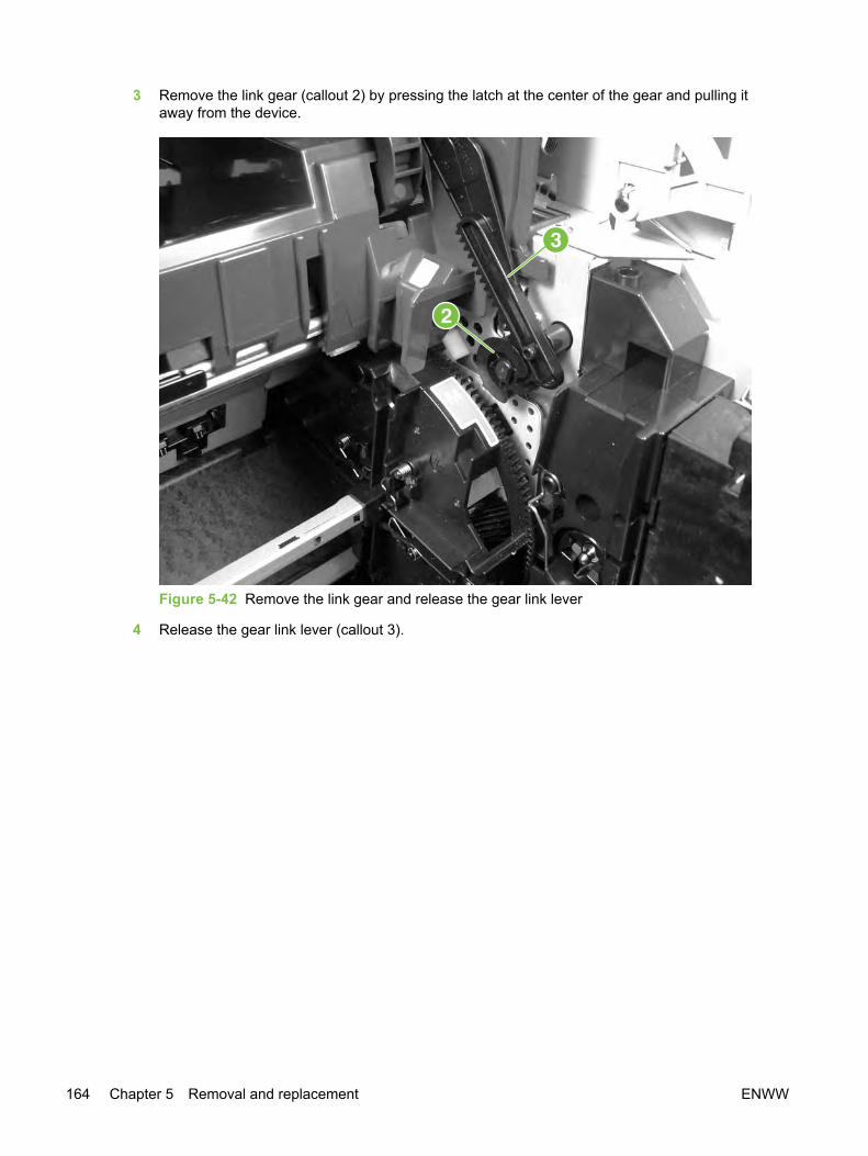
3 Remove the link gear (callout 2) by pressing the latch at the center of the gear and pulling itaway from the device.
Figure 5-42 Remove the link gear and release the gear link lever
4 Release the gear link lever (callout 3).
164 Chapter 5 Removal and replacement ENWW
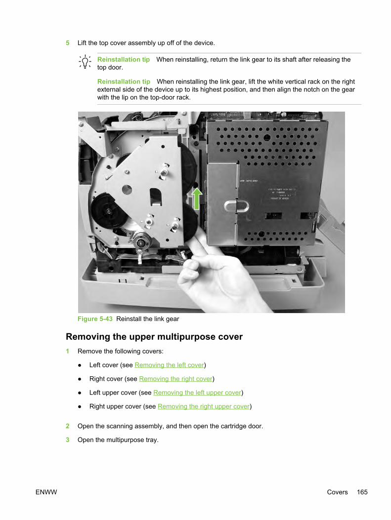
5 Lift the top cover assembly up off of the device.
Reinstallation tip When reinstalling, return the link gear to its shaft after releasing thetop door.
Reinstallation tip When reinstalling the link gear, lift the white vertical rack on the rightexternal side of the device up to its highest position, and then align the notch on the gearwith the lip on the top-door rack.
Figure 5-43 Reinstall the link gear
Removing the upper multipurpose cover1 Remove the following covers:
● Left cover (see Removing the left cover)
● Right cover (see Removing the right cover)
● Left upper cover (see Removing the left upper cover)
● Right upper cover (see Removing the right upper cover)
2 Open the scanning assembly, and then open the cartridge door.
3 Open the multipurpose tray.
ENWW Covers 165

4 At the bottom of the cover, release the two latches (callout 1), one on each side.
Figure 5-44 Remove the upper multipurpose cover (1 of 2)
166 Chapter 5 Removal and replacement ENWW

5 Pull the bottom cover up and away from the device to release the four latches (callout 2) at thetop of the cover.
Figure 5-45 Remove the upper multipurpose cover (2 of 2)
Removing the density sensor and top-of-page sensor1 Remove the upper multipurpose cover (see Removing the upper multipurpose cover).
2 Press the tab (shown in Figure 5-46 Remove the density sensor cover) on the sensor cover torelease the cover, and then lift the cover up and away from the device.
Figure 5-46 Remove the density sensor cover
3 Unplug one connector (callout 2).
4 Remove the two screws (callout 3).
ENWW Covers 167
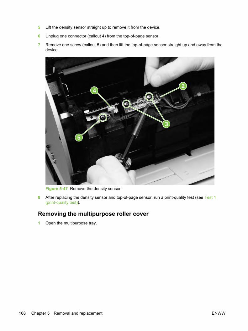
5 Lift the density sensor straight up to remove it from the device.
6 Unplug one connector (callout 4) from the top-of-page sensor.
7 Remove one screw (callout 5) and then lift the top-of-page sensor straight up and away from thedevice.
2
3
5
4
Figure 5-47 Remove the density sensor
8 After replacing the density sensor and top-of-page sensor, run a print-quality test (see Test 1(print-quality test)).
Removing the multipurpose roller cover1 Open the multipurpose tray.
168 Chapter 5 Removal and replacement ENWW
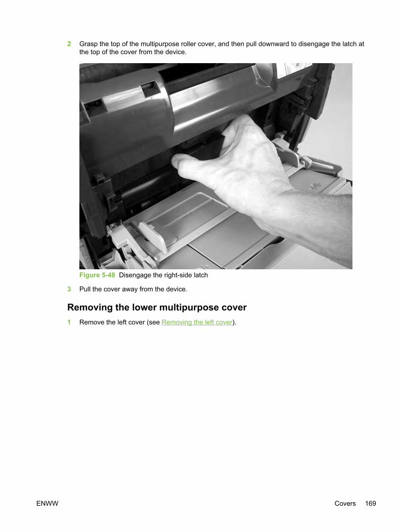
2 Grasp the top of the multipurpose roller cover, and then pull downward to disengage the latch atthe top of the cover from the device.
Figure 5-48 Disengage the right-side latch
3 Pull the cover away from the device.
Removing the lower multipurpose cover1 Remove the left cover (see Removing the left cover).
ENWW Covers 169
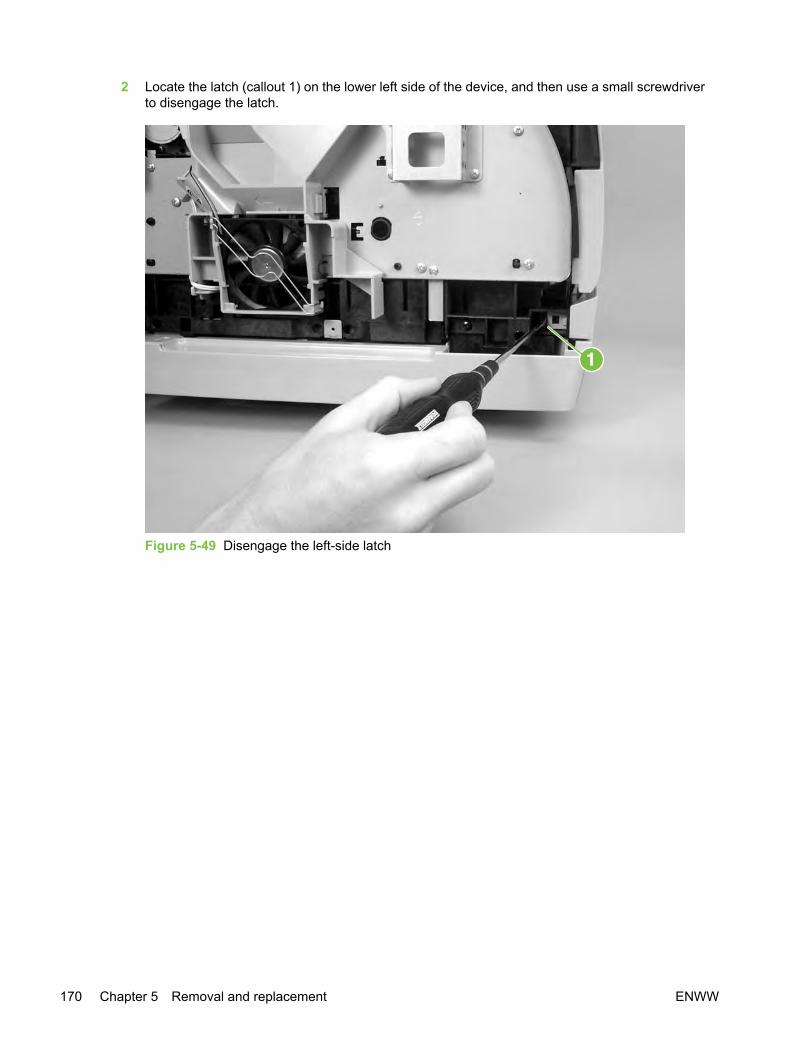
2 Locate the latch (callout 1) on the lower left side of the device, and then use a small screwdriverto disengage the latch.
Figure 5-49 Disengage the left-side latch
170 Chapter 5 Removal and replacement ENWW

3 Pull the left side of the lower multipurpose cover away from the device to disengage the latch atthe right side of the cover.
Figure 5-50 Disengage the right-side latch
ENWW Covers 171

Main assembliesRemoving the control panel1 Remove the control-panel bezel (see Replacing the control-panel bezel).
2 Release the two latches (callout 1) at the bottom of the control panel, and slide the panel slightlyto the left.
3 Using the larger holes (callout 2) at each end of the control panel, gently lift the top of the controlpanel up and away from the device. Disconnect the two cables from the back of the control panel.
Figure 5-51 Remove the control panel
4 After replacing the control panel, run a print-quality test (see Test 1 (print-quality test)) and acopy-quality test (see Test 2 (copy-quality test)).
NOTE If you are servicing an HP Color LaserJet 2840 all-in-one, run a fax-quality test(see Test 3 (fax-quality test)) and a memory-card test (see Test 4 (memory-card test)) aswell.
172 Chapter 5 Removal and replacement ENWW

Removing the left support assembly1 Remove the following covers and assemblies:
● Left cover (see Removing the left cover)
● Left upper cover (see Removing the left upper cover)
● Left rear cover (see Removing the left rear cover)
● I/O cover (see Removing the input/output (I/O) cover)
● Back cover (see Removing the back cover)
● Top cover assembly (see Removing the top cover assembly)
● Scanning assembly (see Removing the scanning assembly)
2 Remove seven screws (callout 1), and then pull the support up and away from the device.
Figure 5-52 Remove the left support assembly
ENWW Main assemblies 173

Removing the right support assembly1 Remove the following covers:
● Right cover (see Removing the right cover)
● Right upper cover (see Removing the right upper cover)
● Right rear cover (see Removing the right rear cover)
● I/O cover (see Removing the input/output (I/O) cover)
● Back cover (see Removing the back cover)
● Top cover assembly (see Removing the top cover assembly)
● Scanning assembly (see Removing the scanning assembly)
● Formatter cage (see Removing the formatter cage)
2 Remove three screws (callout 1) from the front part of the support, and lift the piece away fromthe device.
Figure 5-53 Remove the right support assembly (1 of 2)
174 Chapter 5 Removal and replacement ENWW

3 Remove six screws (callout 2) from the rest of the right support assembly, and then pull thesupport up and away from the device.
Figure 5-54 Remove the right support assembly (2 of 2)
Removing the laser/scanner assembly1 Remove the following covers:
● Top cover assembly (see Removing the top cover assembly)
● I/O cover (see Removing the input/output (I/O) cover)
● Back cover (see Removing the back cover)
2 Unplug the two cable connectors (callout 1), and unroute the cables from the cable holders.
3 Disconnect the flat flexible cable from the cable socket (callout 2) on the laser/scanner.
4 Lift the two forming holders, rotate the lower part of the face-down cover (callout 3) toward thefront of the device, and then lift away from the device.
ENWW Main assemblies 175

5 Remove four screws (callout 4).
1
3
4
2
1
Figure 5-55 Remove the laser/scanner assembly
6 Unroute the cables from the cable harness attached to the back of the laser/scanner.
7 Lift the laser/scanner assembly straight up to remove it from the device.
176 Chapter 5 Removal and replacement ENWW

8 When reinstalling the face-down cover (callout 3 in Figure 5-55 Remove the laser/scannerassembly), place the two forming holders (on the upper face-down roller) on top of the cover, asshown in Figure 5-56 Reinstall the face-down cover.
Figure 5-56 Reinstall the face-down cover
9 After replacing the laser/scanner assembly, run a print-quality test (see Test 1 (print-quality test)).
Removing the transfer-roller plate
CAUTION Do not touch the black sponge portion of the transfer roller.
1 Remove the toner-catch tray (see Removing the toner-catch tray).
ENWW Main assemblies 177
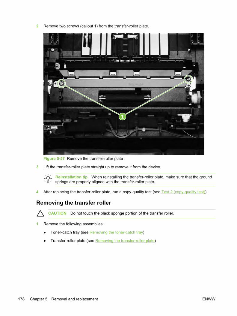
2 Remove two screws (callout 1) from the transfer-roller plate.
1
Figure 5-57 Remove the transfer-roller plate
3 Lift the transfer-roller plate straight up to remove it from the device.
Reinstallation tip When reinstalling the transfer-roller plate, make sure that the groundsprings are properly aligned with the transfer-roller plate.
4 After replacing the transfer-roller plate, run a copy-quality test (see Test 2 (copy-quality test)).
Removing the transfer roller
CAUTION Do not touch the black sponge portion of the transfer roller.
1 Remove the following assemblies:
● Toner-catch tray (see Removing the toner-catch tray)
● Transfer-roller plate (see Removing the transfer-roller plate)
178 Chapter 5 Removal and replacement ENWW

2 Use needle-nose pliers to gently squeeze the small tabs at the right side of the transfer roller(see the detail in Figure 5-58 Remove the transfer roller) and then also squeeze the tabs at theleft side of the transfer roller to release the roller.
Figure 5-58 Remove the transfer roller
NOTE Be careful not to bend the thin metal strip adjacent to the tabs on the right side ofthe roller.
3 Lift the transfer roller up from the right side, slide it to the right, and lift it out of the device.
NOTE The small grounding spring that is underneath the left side of the transfer roller isattached to the transfer roller. It is removed with the transfer roller.
The small grounding spring that is underneath the right side of the transfer roller remainsin the chassis.
4 After replacing the transfer roller, run a copy-quality test (see Test 2 (copy-quality test)).
ENWW Main assemblies 179

Removing the formatter assemblies
Removing the formatter cage1 Remove the following covers and assembly:
● Right cover (see Removing the right cover)
● Right rear cover (see Removing the right rear cover)
● I/O cover (see Removing the input/output (I/O) cover)
2 Detach four or five (HP Color LaserJet 2840 all-in-one only) cables (callout 1) at the top of theformatter cage.
Figure 5-59 Remove the formatter cage (1 of 3)
180 Chapter 5 Removal and replacement ENWW

3 Open the formatter cage memory door, and then use a flatblade screwdriver to push the tab onthe cable connector (callout 2) to unplug the connector.
2
Figure 5-60 Remove the formatter cage (2 of 3)
ENWW Main assemblies 181

4 Remove four screws (callout 3) from the formatter cage, and then lift the formatter to disengagethe hooks at the top of the formatter cage (see inset in Figure 5-61 Remove the formatter cage (3of 3)).
3
Figure 5-61 Remove the formatter cage (3 of 3)
5 Lift the formatter cage up, and then pull it slightly away from the device.
6 Disconnect the flat, flexible cable that connects the back of the formatter cage to the DCcontroller.
7 After replacing the formatter cage, run a print-quality test (see Test 1 (print-quality test)) and acopy-quality test (see Test 2 (copy-quality test)).
NOTE If you are servicing an HP Color LaserJet 2840 all-in-one, run a fax-quality test(see Test 3 (fax-quality test)) and a memory-card test (see Test 4 (memory-card test)) aswell.
Removing the formatter and line interface unit (LIU)1 Remove the formatter cage (see Removing the formatter cage).
2 Remove five screws (callout 1) from the metal plate on the back of the formatter cage, and thenremove the metal plate.
182 Chapter 5 Removal and replacement ENWW
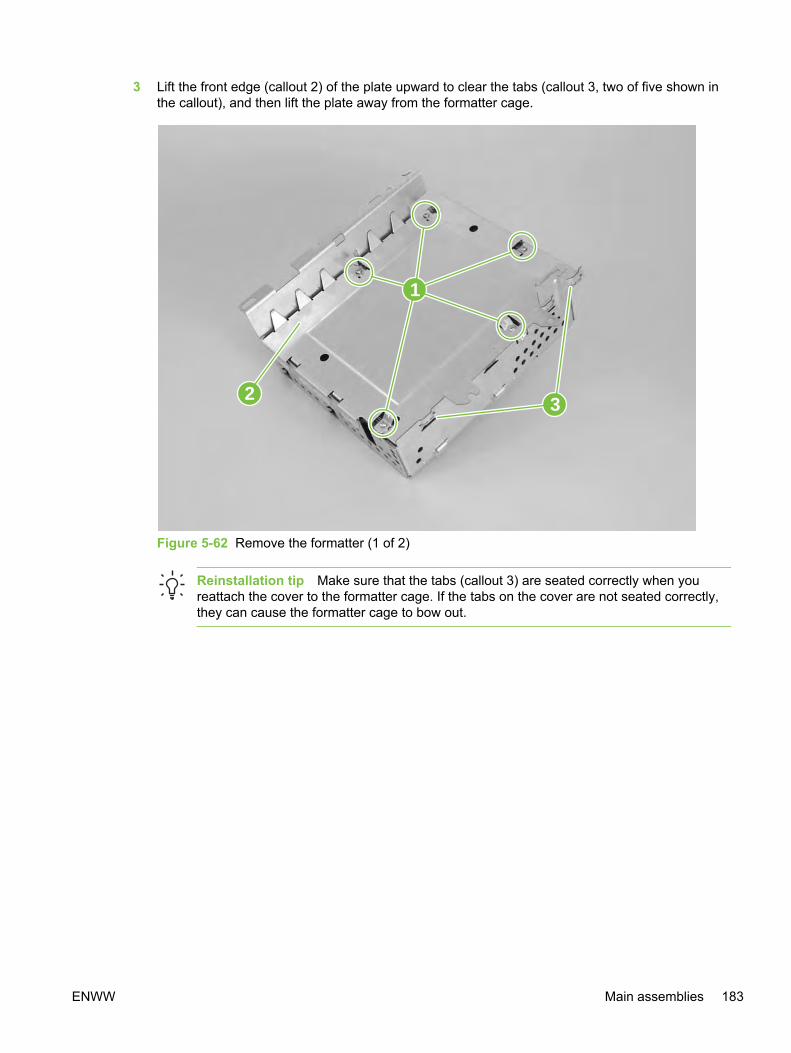
3 Lift the front edge (callout 2) of the plate upward to clear the tabs (callout 3, two of five shown inthe callout), and then lift the plate away from the formatter cage.
2
1
3
Figure 5-62 Remove the formatter (1 of 2)
Reinstallation tip Make sure that the tabs (callout 3) are seated correctly when youreattach the cover to the formatter cage. If the tabs on the cover are not seated correctly,they can cause the formatter cage to bow out.
ENWW Main assemblies 183
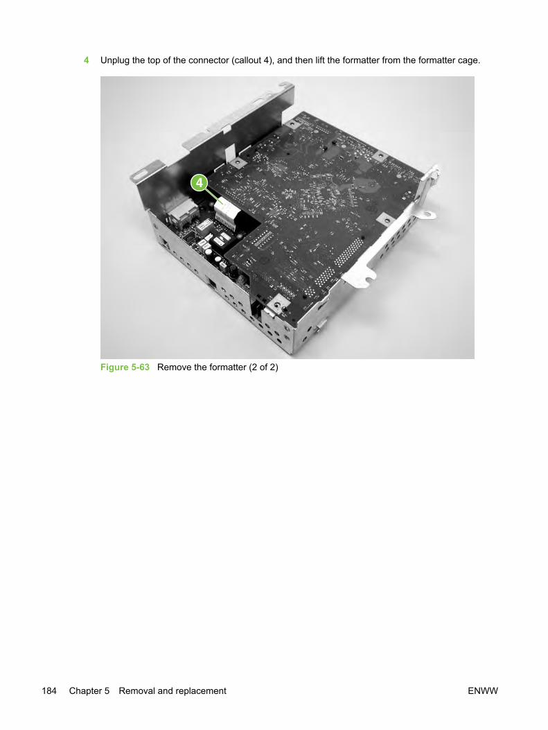
4 Unplug the top of the connector (callout 4), and then lift the formatter from the formatter cage.
Figure 5-63 Remove the formatter (2 of 2)
184 Chapter 5 Removal and replacement ENWW
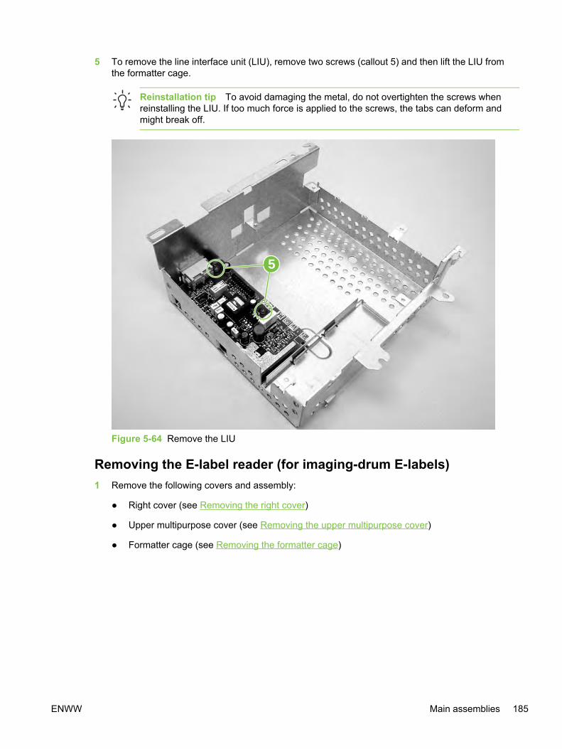
5 To remove the line interface unit (LIU), remove two screws (callout 5) and then lift the LIU fromthe formatter cage.
Reinstallation tip To avoid damaging the metal, do not overtighten the screws whenreinstalling the LIU. If too much force is applied to the screws, the tabs can deform andmight break off.
5
Figure 5-64 Remove the LIU
Removing the E-label reader (for imaging-drum E-labels)1 Remove the following covers and assembly:
● Right cover (see Removing the right cover)
● Upper multipurpose cover (see Removing the upper multipurpose cover)
● Formatter cage (see Removing the formatter cage)
ENWW Main assemblies 185

2 Use a small flatblade screwdriver to lift two tabs (callout 1), one on each side of the E-labelreader housing.
1
Figure 5-65 Remove the E-label reader (1 of 2)
3 Slide the E-label reader off of its rails.
186 Chapter 5 Removal and replacement ENWW

4 Unplug the E-label reader connector (callout 2) from the DC controller.
NOTE Examine the cable routing as you lift the E-label reader from the device.
2
Figure 5-66 Remove the E-label reader (2 of 2)
5 After replacing the E-label reader, run a print-quality test (see Test 1 (print-quality test)) and acopy-quality test (see Test 2 (copy-quality test)).
NOTE If you are servicing an HP Color LaserJet 2840 all-in-one, run a memory-card test(see Test 4 (memory-card test)) as well.
Removing the DC controller1 Remove the formatter cage (see Removing the formatter cage).
2 Unplug the two flat, flexible cables (callout 1).
3 Release the cables from two cable-holders (callout 2).
4 Unplug one cable connector (callout 3) by pressing and releasing the tab on the side of theconnector.
5 Unplug two cable connectors (callout 4) by releasing a clip on each connector (see the detail inthe lower-left corner of Figure 5-67 Remove the DC controller).
ENWW Main assemblies 187

6 Unplug the remaining 24 cable connectors, and then remove the two screws (callout 5) at thebottom of the DC controller before removing two screws (callout 6) at the top of the DC controller.
Figure 5-67 Remove the DC controller
7 Lift the DC controller up and then away from the device.
Reinstallation tip The connection that remains empty upon reinstallation is shown incallout 7 in Figure 5-67 Remove the DC controller. The connection is used to update theDC controller firmware.
Reinstallation tip When reinstalling the DC controller, avoid overtightening the screws,which can damage parts of the device.
8 After replacing the DC controller, run a print-quality test (see Test 1 (print-quality test)) and acopy-quality test (see Test 2 (copy-quality test)).
NOTE If you are servicing an HP Color LaserJet 2840 all-in-one, run a fax-quality test(see Test 3 (fax-quality test)) and a memory-card test (see Test 4 (memory-card test)) aswell.
188 Chapter 5 Removal and replacement ENWW
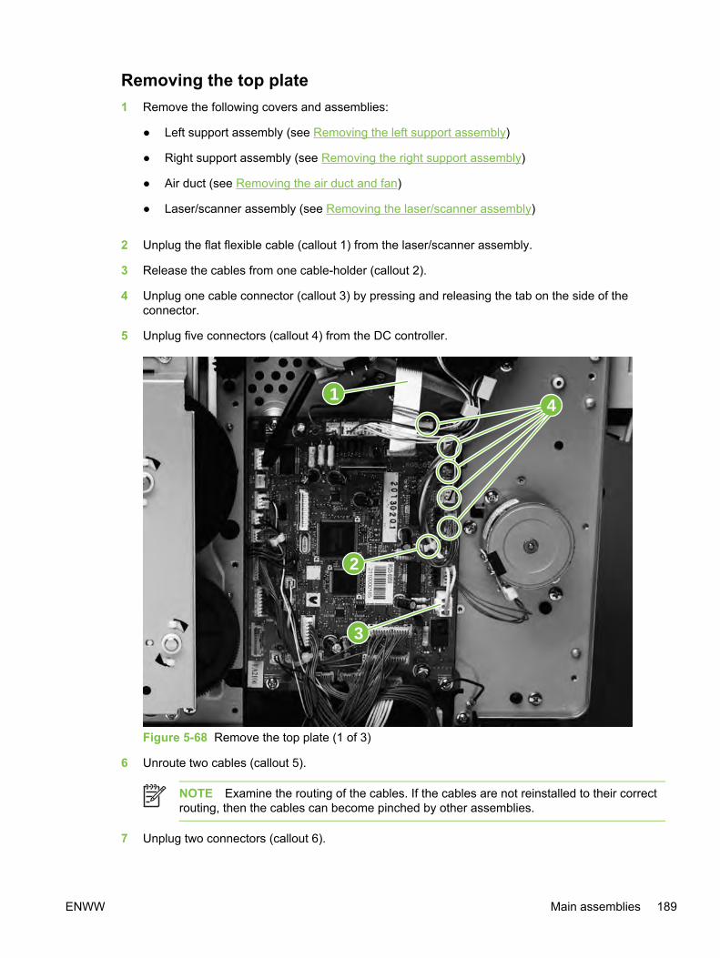
Removing the top plate1 Remove the following covers and assemblies:
● Left support assembly (see Removing the left support assembly)
● Right support assembly (see Removing the right support assembly)
● Air duct (see Removing the air duct and fan)
● Laser/scanner assembly (see Removing the laser/scanner assembly)
2 Unplug the flat flexible cable (callout 1) from the laser/scanner assembly.
3 Release the cables from one cable-holder (callout 2).
4 Unplug one cable connector (callout 3) by pressing and releasing the tab on the side of theconnector.
5 Unplug five connectors (callout 4) from the DC controller.
2
3
41
Figure 5-68 Remove the top plate (1 of 3)
6 Unroute two cables (callout 5).
NOTE Examine the routing of the cables. If the cables are not reinstalled to their correctrouting, then the cables can become pinched by other assemblies.
7 Unplug two connectors (callout 6).
ENWW Main assemblies 189

8 Remove two screws at the left side of the device (callout 7) and then remove the twocorresponding screws from the right side of the device.
Figure 5-69 Remove the top plate (2 of 3)
190 Chapter 5 Removal and replacement ENWW

9 The "hidden" screw in callout 7 secures a grounding plate (callout 8) to the chassis. Removingthe screw releases the grounding plate. Upon reinstallation of the top plate, make sure that thegrounding plate tab is in its correct position on the outside of the carousel drive shaft.
8
Figure 5-70 Reinstall the grounding plate
ENWW Main assemblies 191
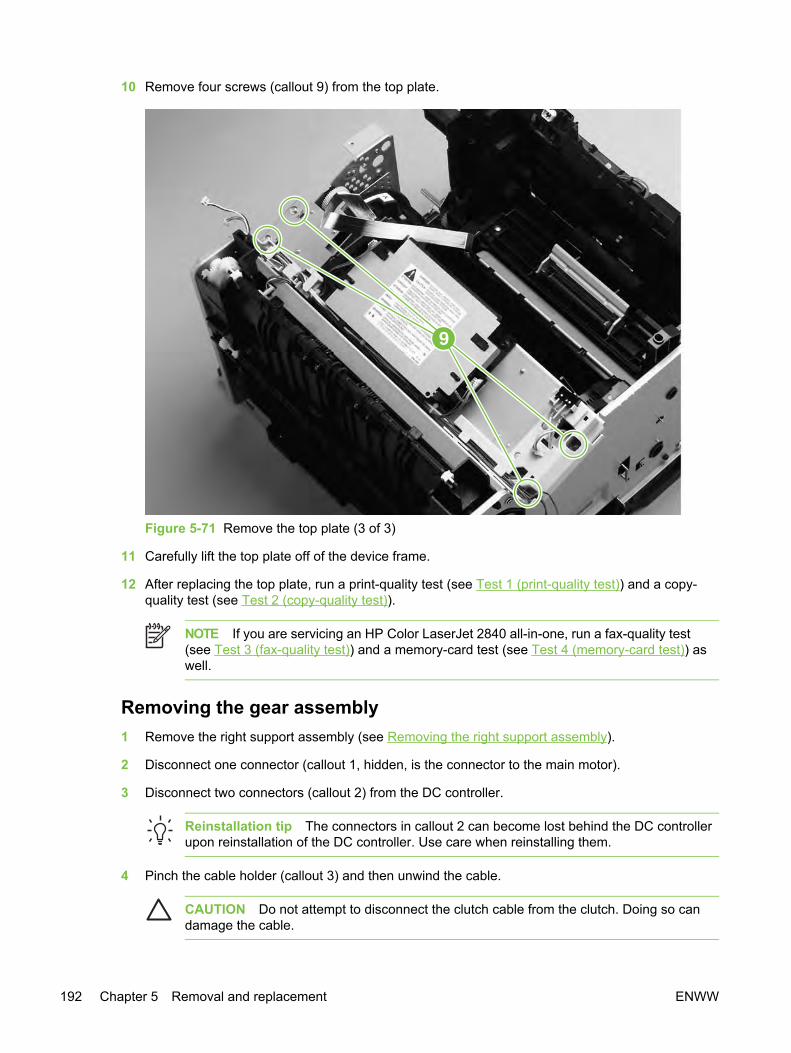
10 Remove four screws (callout 9) from the top plate.
9
Figure 5-71 Remove the top plate (3 of 3)
11 Carefully lift the top plate off of the device frame.
12 After replacing the top plate, run a print-quality test (see Test 1 (print-quality test)) and a copy-quality test (see Test 2 (copy-quality test)).
NOTE If you are servicing an HP Color LaserJet 2840 all-in-one, run a fax-quality test(see Test 3 (fax-quality test)) and a memory-card test (see Test 4 (memory-card test)) aswell.
Removing the gear assembly1 Remove the right support assembly (see Removing the right support assembly).
2 Disconnect one connector (callout 1, hidden, is the connector to the main motor).
3 Disconnect two connectors (callout 2) from the DC controller.
Reinstallation tip The connectors in callout 2 can become lost behind the DC controllerupon reinstallation of the DC controller. Use care when reinstalling them.
4 Pinch the cable holder (callout 3) and then unwind the cable.
CAUTION Do not attempt to disconnect the clutch cable from the clutch. Doing so candamage the cable.
192 Chapter 5 Removal and replacement ENWW

5 Remove the e-clip (callout 4) from the clutch, and then pull the clutch away from the device.
6 Remove the uppermost gear (callout 5) from the rack (callout 6) by pushing the gear's shaft fromthe inside of the device with the rack in its lowest position.
6
51
2
3
4
Figure 5-72 Remove the gear assembly (1 of 2)
7 Remove eight screws (callout 7) from the gear plate.
ENWW Main assemblies 193

8 Rotate the gear assembly away from the device, beginning with the front edge.
NOTE A grounding spring (callout 8, hidden) should remain attached to the devicechassis. If it does not, then either reattach it to the chassis or place it with the gearassembly to prevent misplacing it.
7
8
Figure 5-73 Remove the gear assembly (2 of 2)
Reinstallation tip A grounding wire at the lower-back corner of the gear assembly mustbe hooked around the chassis at reinstallation. Callout 2 in Figure 5-74 Remove the waste-toner sensor shows the grounding wire, and callout 3 shows the grounding springattached to the chassis.
When reinstalling, align the following parts with the device chassis:
● Gear assembly shaft (at the bottom of the gear assembly)
● Grounding spring (callout 3 in Figure 5-74 Remove the waste-toner sensor)
● Grounding wire (callout 2 in Figure 5-74 Remove the waste-toner sensor)
9 After replacing the gear assembly, run a print-quality test (see Test 1 (print-quality test)) and acopy-quality test (see Test 2 (copy-quality test)).
NOTE If you are servicing an HP Color LaserJet 2840 all-in-one, run a fax-quality test(see Test 3 (fax-quality test)) and a memory-card test (see Test 4 (memory-card test)) aswell.
194 Chapter 5 Removal and replacement ENWW
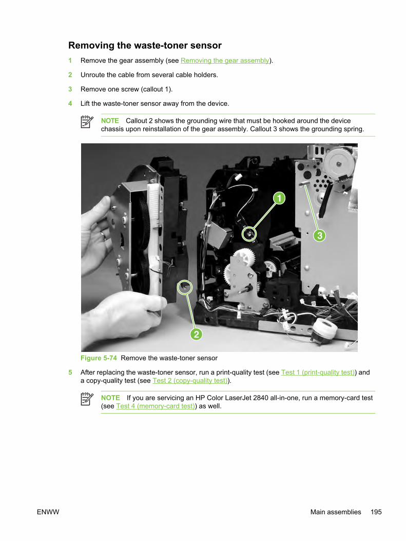
Removing the waste-toner sensor1 Remove the gear assembly (see Removing the gear assembly).
2 Unroute the cable from several cable holders.
3 Remove one screw (callout 1).
4 Lift the waste-toner sensor away from the device.
NOTE Callout 2 shows the grounding wire that must be hooked around the devicechassis upon reinstallation of the gear assembly. Callout 3 shows the grounding spring.
Figure 5-74 Remove the waste-toner sensor
5 After replacing the waste-toner sensor, run a print-quality test (see Test 1 (print-quality test)) anda copy-quality test (see Test 2 (copy-quality test)).
NOTE If you are servicing an HP Color LaserJet 2840 all-in-one, run a memory-card test(see Test 4 (memory-card test)) as well.
ENWW Main assemblies 195

Removing the rotary-drive assembly
NOTE The rotary-drive assembly includes the developer motor, the brake solenoid, and theencoder motor.
1 Remove the following assemblies:
● Left support assembly (see Removing the left support assembly)
● Right support assembly (see Removing the right support assembly)
2 Unplug three cable connectors (callout 1) from the DC controller and unplug the flat laser/scanner cable (callout 2) from the laser/scanner.
1
2
Figure 5-75 Remove the rotary-drive assembly (1 of 3)
3 Remove one screw (callout 3) from the motor.
196 Chapter 5 Removal and replacement ENWW

4 Remove one of the four screws that secures the rotary-drive assembly to the chassis (callout 4).
3
4
Figure 5-76 Remove the rotary-drive assembly (2 of 3)
ENWW Main assemblies 197

5 From the top of the device, remove the other three screws that secure the rotary-drive assemblyto the chassis (callout 5).
5
Figure 5-77 Remove the rotary-drive assembly (3 of 3)
6 Lift the rotary-drive assembly straight up to remove it from the device.
Reinstallation tip Insert the metal protrusion at the back of the rotary-drive assemblyinto the slot in the rear frame assembly and then lower the rotary-drive assembly intoposition over the alignment pins. Make sure that no cables are pinched.
7 After replacing the rotary-drive assembly, run a print-quality test (see Test 1 (print-quality test))and a copy-quality test (see Test 2 (copy-quality test)).
NOTE If you are servicing an HP Color LaserJet 2840 all-in-one, run a fax-quality test(see Test 3 (fax-quality test)) and a memory-card test (see Test 4 (memory-card test)) aswell.
198 Chapter 5 Removal and replacement ENWW

Removing the print-cartridge carousel1 Remove the following covers and assemblies:
● Formatter cage (see Removing the formatter cage)
● Fuser assembly (see Replacing the fuser assembly)
● Left support assembly (see Removing the left support assembly)
● Right support assembly (see Removing the right support assembly)
● Air duct (see Removing the air duct and fan)
● Rotary-drive assembly (see Removing the rotary-drive assembly)
● Top plate (see Removing the top plate)
2 Remove two screws (callout 1) from the back of the device.
1
Figure 5-78 Remove the print-cartridge carousel (1 of 3)
Reinstallation tip Because the remainder of the print-cartridge carousel removalprocedures are performed from the left, right, and front of the device, it is easy to forget toreplace the two screws at the back of the device.
ENWW Main assemblies 199

3 Press the white plastic tab (callout 2) at the left side of the device to release the left swing-shaftbushing, and then rotate the bushing to a vertical position.
2
Figure 5-79 Remove the print-cartridge carousel (2 of 3)
4 On the right side of the device, repeat step 3 on the right swing-shaft bushing.
Examine the positions of the left pressure-shaft holder (callout 3), the right pressure-shaft holder(callout 4), and the pressure-shaft gear (callout 5) before you perform step 5. The pressure-shaftholders must be reinstalled to their correct positions when reinstalling the print-cartridge carousel.
200 Chapter 5 Removal and replacement ENWW
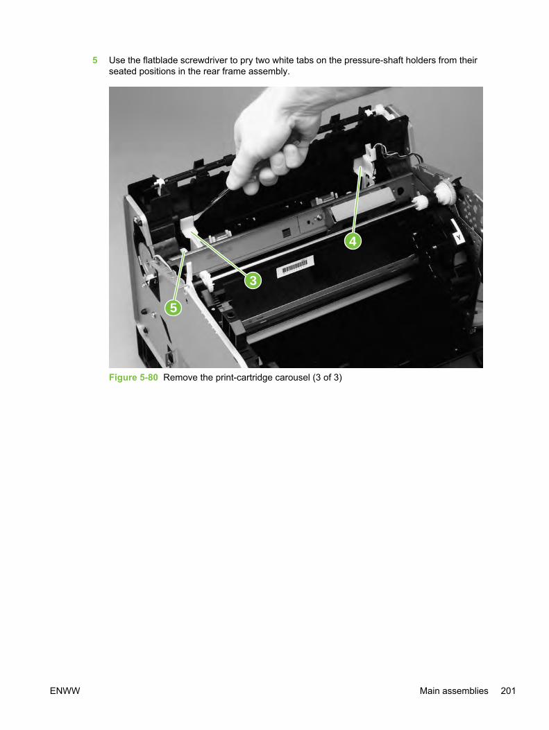
5 Use the flatblade screwdriver to pry two white tabs on the pressure-shaft holders from theirseated positions in the rear frame assembly.
3
5
4
Figure 5-80 Remove the print-cartridge carousel (3 of 3)
ENWW Main assemblies 201

6 Lift the print-cartridge carousel out of the device.
Incorrect reinstallation of the "feet" is shown, followed by correct installation.
Figure 5-81 Installation of “feet” (1 of 2)
Figure 5-81 Installation of “feet” (2 of 2)
Also make sure that the tab on the pressure-shaft gear points down.
Figure 5-82 Correct gear placement
7 After replacing the print-cartridge carousel, run a print-quality test (see Test 1 (print-quality test))and a copy-quality test (see Test 2 (copy-quality test)).
202 Chapter 5 Removal and replacement ENWW

NOTE If you are servicing an HP Color LaserJet 2840 all-in-one, run a fax-quality test(see Test 3 (fax-quality test)) and a memory-card test (see Test 4 (memory-card test)) aswell.
Aligning the carousel gearsMake sure that the gears in the print-cartridge carousel are aligned correctly before placing thecarousel back into the device.
1 Rotate the carousel so that the marker for the yellow print cartridge faces the front of the device.
2 Examine the gears: two marks on the smaller gear should line up with the single mark on thelarger gear (see the detail of the gears in Figure 5-83 Reinstall the print-cartridge carousel).
NOTE The single mark on the larger gear is adjacent to the slot for the black cartridge,marked with a "K."
3 If the gears are not aligned correctly, locate the marks on the gears and realign the gears.
Figure 5-83 Reinstall the print-cartridge carousel
ENWW Main assemblies 203

Removing the registration-roller assembly1 Remove two screws (callout 1) from the registration-shutter assembly.
1
Figure 5-84 Remove the registration-roller assembly
2 Rotate the registration-roller assembly toward the front of the device and then lift it towards therear of the device and up to remove it from the device.
3 After replacing the registration-roller assembly, run a print-quality test (see Test 1 (print-qualitytest)).
Removing the toner-catch trayThe toner-catch tray is secured by two tabs underneath the tray (see Figure 5-85 Remove the toner-catch tray), toward the front of the tray.
1 Remove the print cartridges (see Replacing the print cartridges) and the imaging drum (seeReplacing the imaging drum).
2 Release one tab on either side of the toner-catch tray and then pull the tray approximately 2 or 3mm (approximately 0.125 inch) toward the front of the device to make sure that the tab does notreattach as you perform the next step.
204 Chapter 5 Removal and replacement ENWW
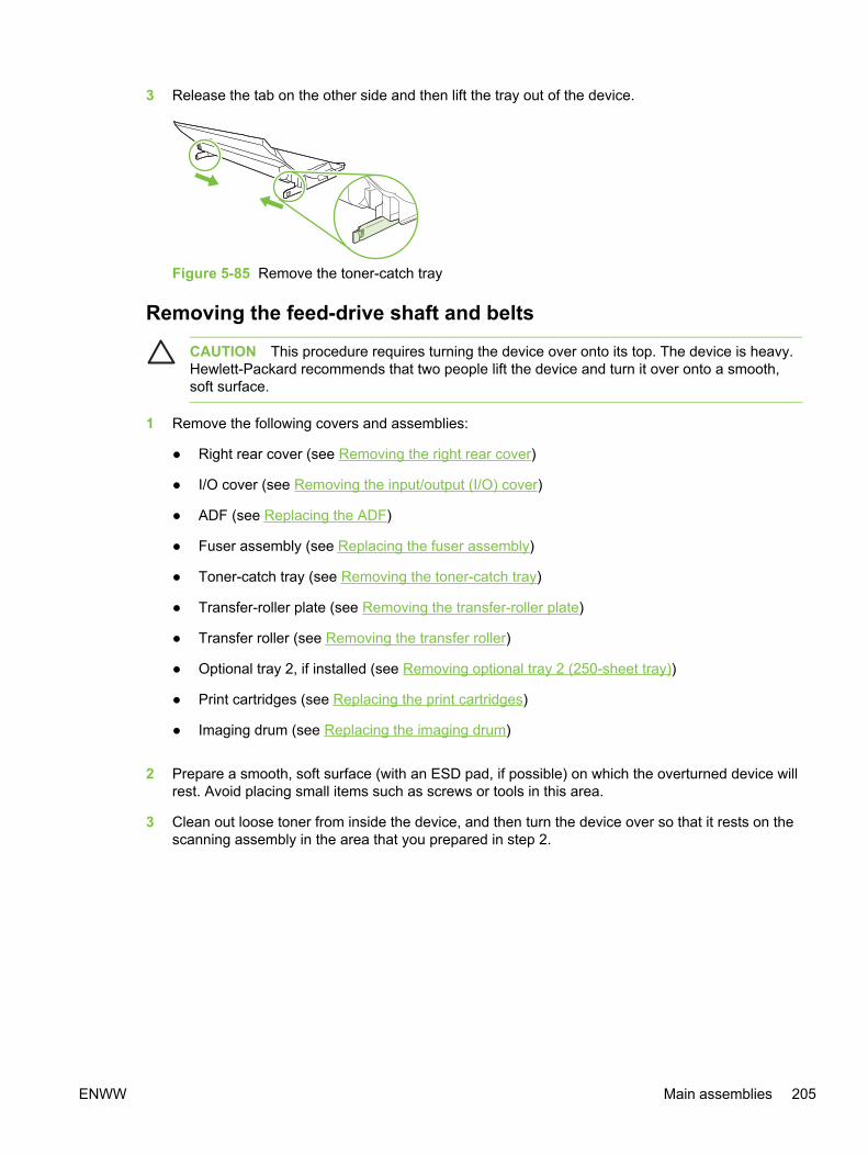
3 Release the tab on the other side and then lift the tray out of the device.
Figure 5-85 Remove the toner-catch tray
Removing the feed-drive shaft and belts
CAUTION This procedure requires turning the device over onto its top. The device is heavy.Hewlett-Packard recommends that two people lift the device and turn it over onto a smooth,soft surface.
1 Remove the following covers and assemblies:
● Right rear cover (see Removing the right rear cover)
● I/O cover (see Removing the input/output (I/O) cover)
● ADF (see Replacing the ADF)
● Fuser assembly (see Replacing the fuser assembly)
● Toner-catch tray (see Removing the toner-catch tray)
● Transfer-roller plate (see Removing the transfer-roller plate)
● Transfer roller (see Removing the transfer roller)
● Optional tray 2, if installed (see Removing optional tray 2 (250-sheet tray))
● Print cartridges (see Replacing the print cartridges)
● Imaging drum (see Replacing the imaging drum)
2 Prepare a smooth, soft surface (with an ESD pad, if possible) on which the overturned device willrest. Avoid placing small items such as screws or tools in this area.
3 Clean out loose toner from inside the device, and then turn the device over so that it rests on thescanning assembly in the area that you prepared in step 2.
ENWW Main assemblies 205
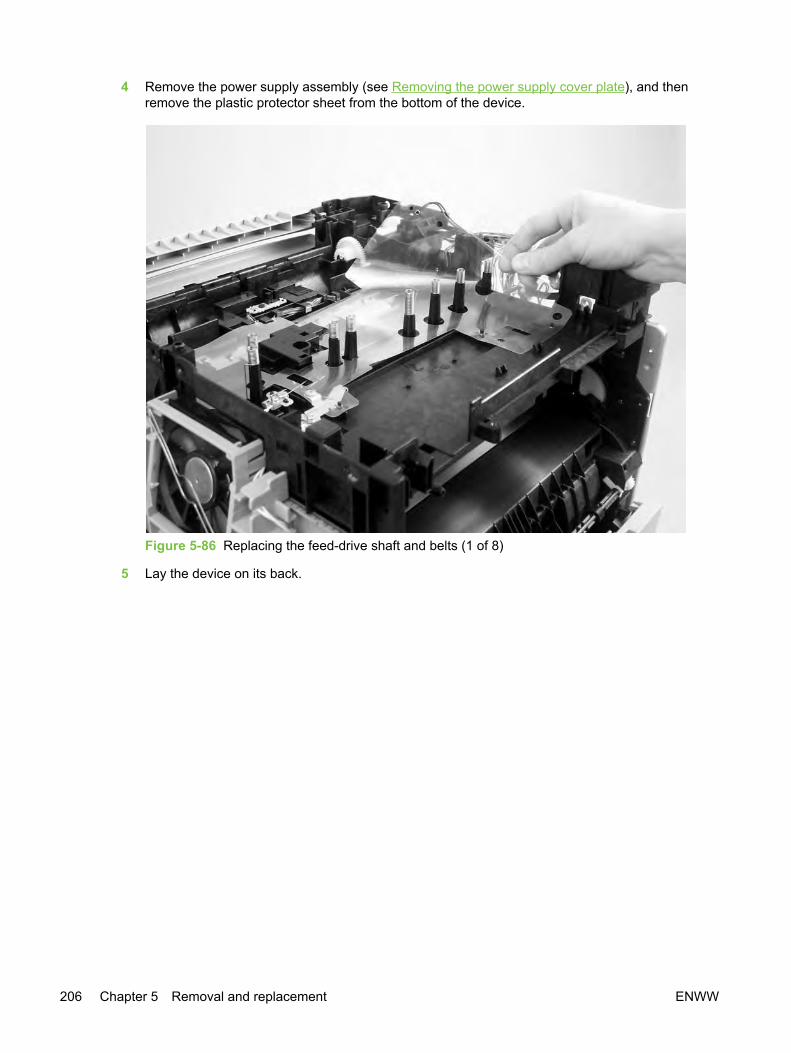
4 Remove the power supply assembly (see Removing the power supply cover plate), and thenremove the plastic protector sheet from the bottom of the device.
Figure 5-86 Replacing the feed-drive shaft and belts (1 of 8)
5 Lay the device on its back.
206 Chapter 5 Removal and replacement ENWW

6 With one hand holding the belt roller shaft on the inside of the device, use the other hand tosimultaneously push both the hooks (callout 1) of the spring clip through the holes in the bottomof the printer. Use care not to loosen the spring clip.
Figure 5-87 Replacing the feed-drive shaft and belts (2 of 8)
ENWW Main assemblies 207
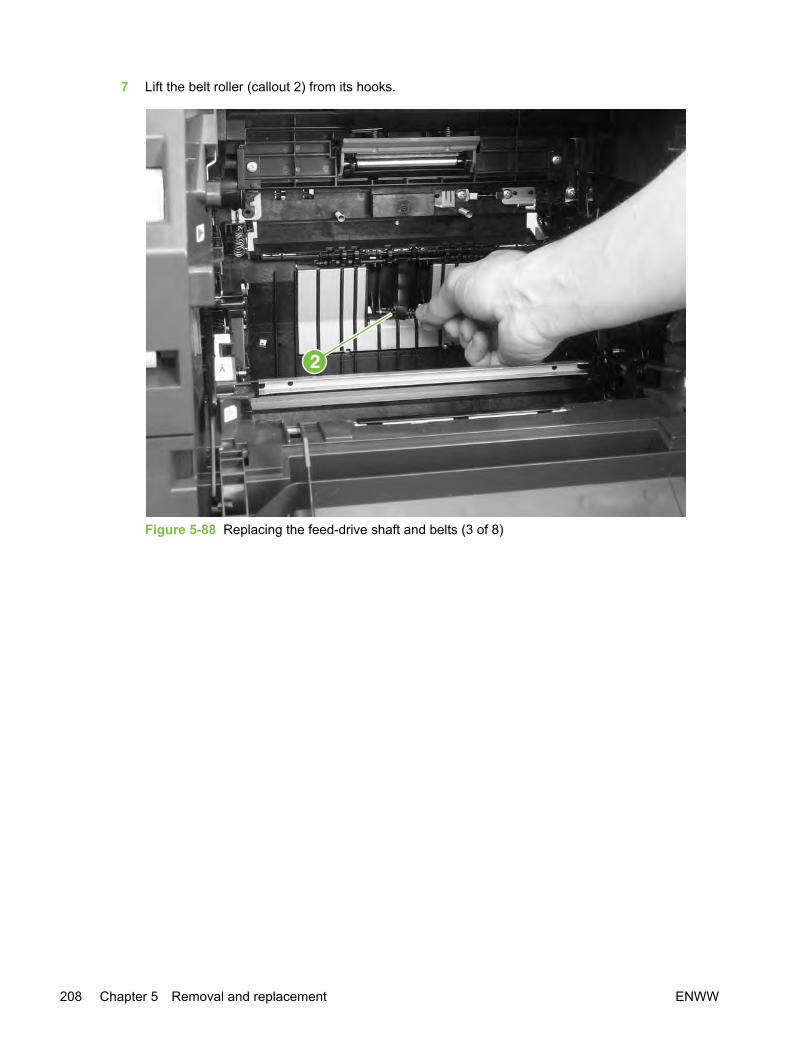
7 Lift the belt roller (callout 2) from its hooks.
Figure 5-88 Replacing the feed-drive shaft and belts (3 of 8)
208 Chapter 5 Removal and replacement ENWW

8 Remove one screw (callout 3) from the gear cover, and then lift the gear cover to remove it.
Figure 5-89 Replacing the feed-drive shaft and belts (4 of 8)
ENWW Main assemblies 209
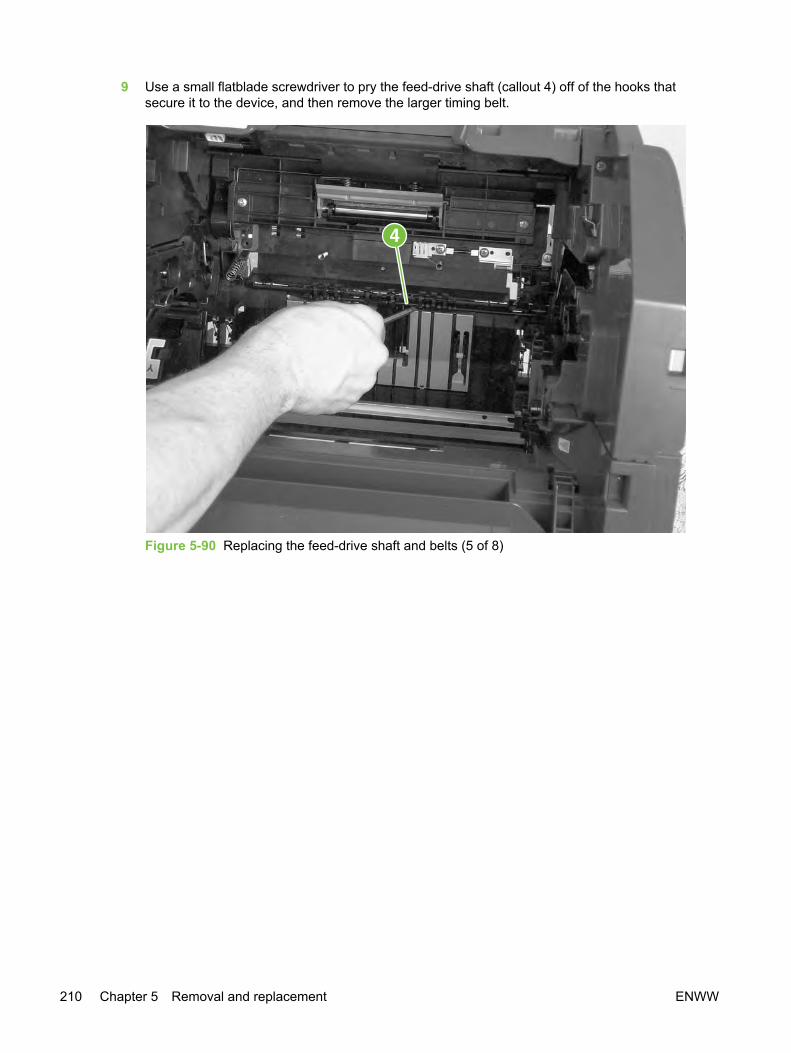
9 Use a small flatblade screwdriver to pry the feed-drive shaft (callout 4) off of the hooks thatsecure it to the device, and then remove the larger timing belt.
Figure 5-90 Replacing the feed-drive shaft and belts (5 of 8)
210 Chapter 5 Removal and replacement ENWW
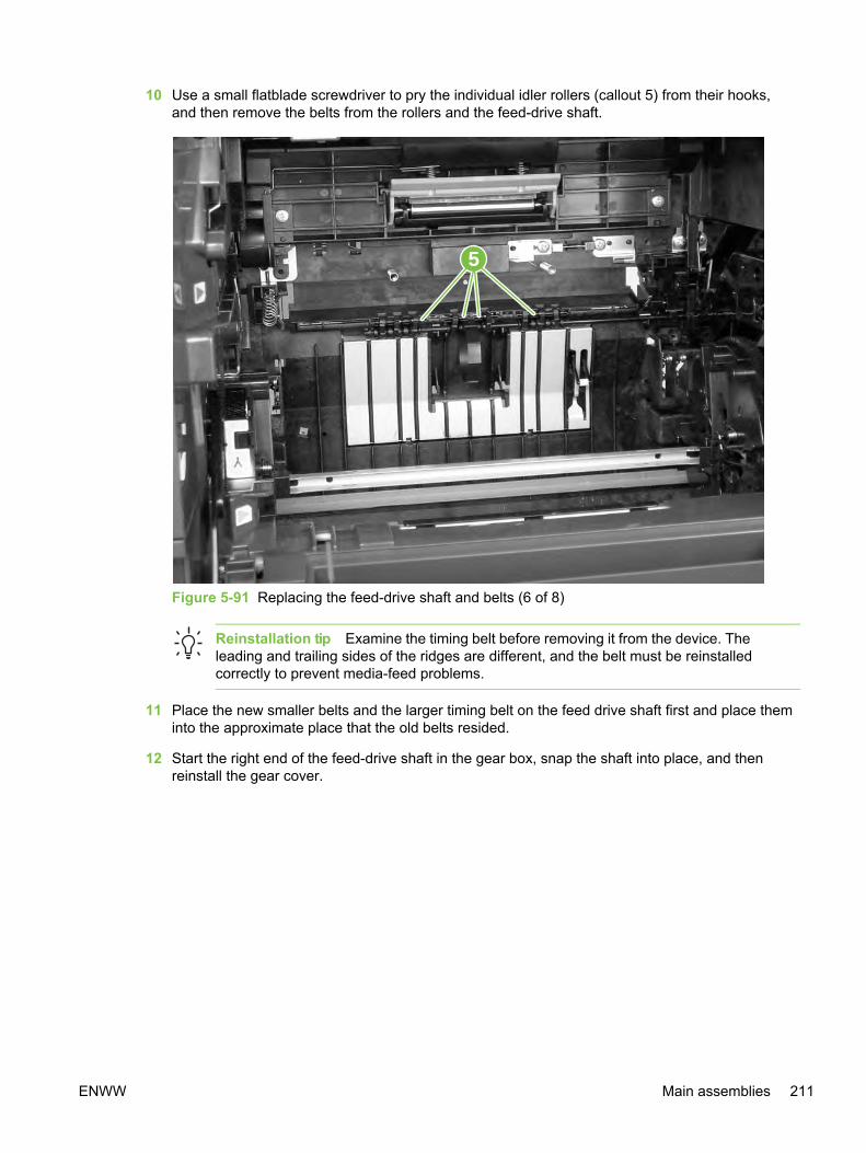
10 Use a small flatblade screwdriver to pry the individual idler rollers (callout 5) from their hooks,and then remove the belts from the rollers and the feed-drive shaft.
5
Figure 5-91 Replacing the feed-drive shaft and belts (6 of 8)
Reinstallation tip Examine the timing belt before removing it from the device. Theleading and trailing sides of the ridges are different, and the belt must be reinstalledcorrectly to prevent media-feed problems.
11 Place the new smaller belts and the larger timing belt on the feed drive shaft first and place theminto the approximate place that the old belts resided.
12 Start the right end of the feed-drive shaft in the gear box, snap the shaft into place, and thenreinstall the gear cover.
ENWW Main assemblies 211
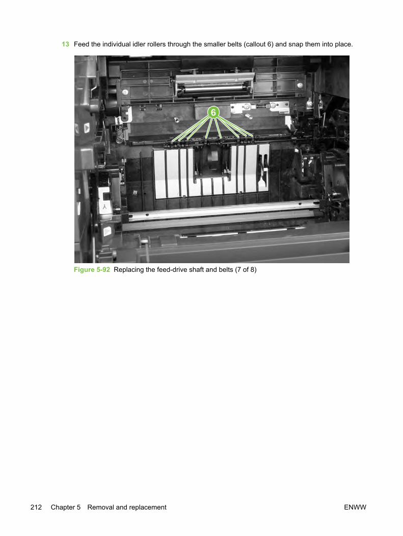
13 Feed the individual idler rollers through the smaller belts (callout 6) and snap them into place.
6
Figure 5-92 Replacing the feed-drive shaft and belts (7 of 8)
212 Chapter 5 Removal and replacement ENWW

14 Put the feed belt on the roller shaft, and then put the spring clip on the shaft so that the hooks ofthe spring clip face the front of the device.
Figure 5-93 Replacing the feed-drive shaft and belts (8 of 8)
15 Push the spring clip hooks through the slots in the bottom of the device, and then push the hookstoward the front of the device to fasten them to the bottom of the device (see Figure 5-87Replacing the feed-drive shaft and belts (2 of 8)).
16 After reassembling the device, run a print-quality test (see Test 1 (print-quality test)) and a copy-quality test (see Test 2 (copy-quality test)).
NOTE If you are servicing an HP Color LaserJet 2840 all-in-one, run a memory-card test(see Test 4 (memory-card test)) as well.
ENWW Main assemblies 213

Removing the power supply cover plate
CAUTION This procedure requires turning the device over onto its top. The device is heavy.Hewlett-Packard recommends that two people lift the device and turn it over onto a smooth,soft surface.
1 Remove the following covers and assemblies:
● ADF (see Replacing the ADF)
● Left cover (see Removing the left cover)
● Right cover (see Removing the right cover)
● Left rear cover (see Removing the left rear cover)
● Right rear cover (see Removing the right rear cover)
● I/O cover (see Removing the input/output (I/O) cover)
● Back cover (see Removing the back cover)
● Fuser assembly (see Replacing the fuser assembly)
● Top cover assembly (see Removing the top cover assembly)
● Formatter cage (see Removing the formatter cage)
● Optional tray 2 (see Removing optional tray 2 (250-sheet tray))
● Toner-catch tray (see Removing the toner-catch tray)
2 Prepare a smooth, soft surface (with an ESD pad, if possible) on which the overturned device willrest. Avoid placing small items such as screws or tools in this area.
3 Unplug five cable connectors (callout 1) from the DC controller, and then unroute the cables fromthe clip in the bottom of the plate.
214 Chapter 5 Removal and replacement ENWW

4 Remove one screw (callout 2) from the grounding wire.
1
2
Figure 5-94 Remove the power supply cover plate (1 of 2)
ENWW Main assemblies 215

5 Clean out loose toner from inside the device, and then turn the device over so that it rests on thescanning assembly in the area that you prepared in step 2.
Figure 5-95 Remove the power supply cover plate (2 of 3)
6 Remove one screw from the left side of the device (callout 3).
216 Chapter 5 Removal and replacement ENWW

7 Remove eight screws (callout 4) from the bottom of the power supply cover plate.
4
3
Figure 5-96 Remove the power supply cover plate (3 of 3)
8 Lift the power supply cover plate off of the device.
ENWW Main assemblies 217

9 During reinstallation, make sure that the grounding springs are attached to each of the eightpower supply cover plate connections before reinstalling the plate.
Figure 5-97 Power supply cover plate connections
10 After replacing the power supply cover plate, run a print-quality test (see Test 1 (print-qualitytest)) and a copy-quality test (see Test 2 (copy-quality test)).
NOTE If you are servicing an HP Color LaserJet 2840 all-in-one, run a memory-card test(see Test 4 (memory-card test)) as well.
Removing the paper-top sensor1 Remove the following assemblies:
● Fuser assembly (see Replacing the fuser assembly)
● Optional tray 2 (see Removing optional tray 2 (250-sheet tray))
● Toner-catch tray (see Removing the toner-catch tray)
● Power supply cover plate (see Removing the power supply cover plate).
218 Chapter 5 Removal and replacement ENWW
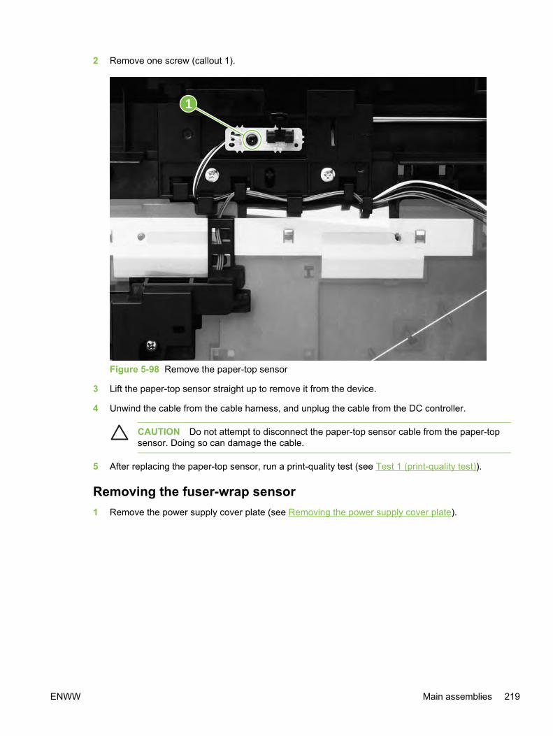
2 Remove one screw (callout 1).
1
Figure 5-98 Remove the paper-top sensor
3 Lift the paper-top sensor straight up to remove it from the device.
4 Unwind the cable from the cable harness, and unplug the cable from the DC controller.
CAUTION Do not attempt to disconnect the paper-top sensor cable from the paper-topsensor. Doing so can damage the cable.
5 After replacing the paper-top sensor, run a print-quality test (see Test 1 (print-quality test)).
Removing the fuser-wrap sensor1 Remove the power supply cover plate (see Removing the power supply cover plate).
ENWW Main assemblies 219

2 Inside the device, remove the fuser-wrap sensor roller (callout 1).
Figure 5-99 Remove the fuser-wrap sensor (1 of 2)
220 Chapter 5 Removal and replacement ENWW
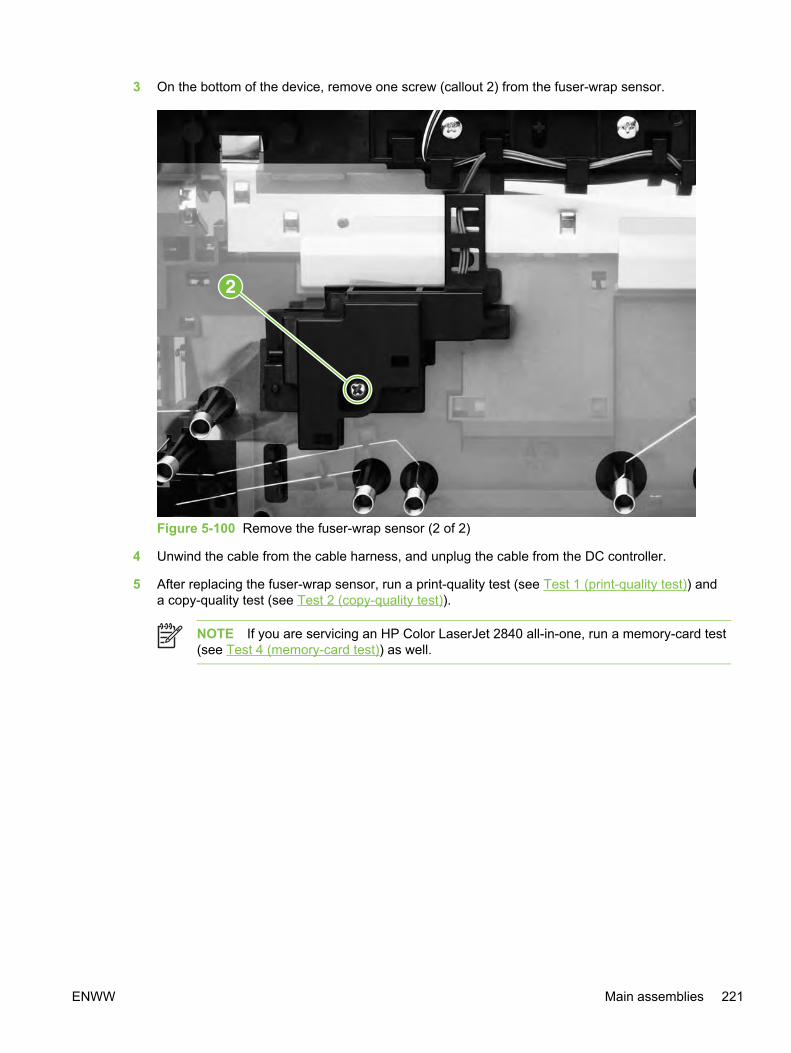
3 On the bottom of the device, remove one screw (callout 2) from the fuser-wrap sensor.
Figure 5-100 Remove the fuser-wrap sensor (2 of 2)
4 Unwind the cable from the cable harness, and unplug the cable from the DC controller.
5 After replacing the fuser-wrap sensor, run a print-quality test (see Test 1 (print-quality test)) anda copy-quality test (see Test 2 (copy-quality test)).
NOTE If you are servicing an HP Color LaserJet 2840 all-in-one, run a memory-card test(see Test 4 (memory-card test)) as well.
ENWW Main assemblies 221

Motors and fansRemoving the fuser motor1 Remove the following covers and assembly:
● Right cover (see Removing the right cover)
● I/O cover (see Removing the input/output (I/O) cover)
● Formatter cage (see Removing the formatter cage)
2 Unplug one connector (callout 1).
3 Remove four screws (callout 2).
1
2
2
Figure 5-101 Remove the fuser motor
4 Pull the motor away from the device.
5 After replacing the fuser motor, run a print-quality test (see Test 1 (print-quality test)) and a copy-quality test (see Test 2 (copy-quality test)).
NOTE If you are servicing an HP Color LaserJet 2840 all-in-one, run a memory-card test(see Test 4 (memory-card test)) as well.
222 Chapter 5 Removal and replacement ENWW

Removing the carousel-engagement motor1 Remove the left cover (see Removing the left cover).
2 Unplug the cable connector (callout 1).
3 Remove two screws (callout 2).
4 Rotate the motor counterclockwise to clear the metal lock-tab.
5 Pull the carousel-engagement motor away from the device to remove it.
12
Figure 5-102 Remove the carousel-engagement motor
6 After replacing the carousel-engagement motor, run a print-quality test (see Test 1 (print-qualitytest)).
Removing the air duct and fan1 Remove the following covers:
● Top cover (see Removing the top cover assembly)
● Left support assembly (see Removing the left support assembly)
2 Disconnect the black connector (callout 1), and then unroute the wires (callout 2) with whiteconnectors from the left side of the air duct.
3 Release two tabs (callout 3).
ENWW Motors and fans 223
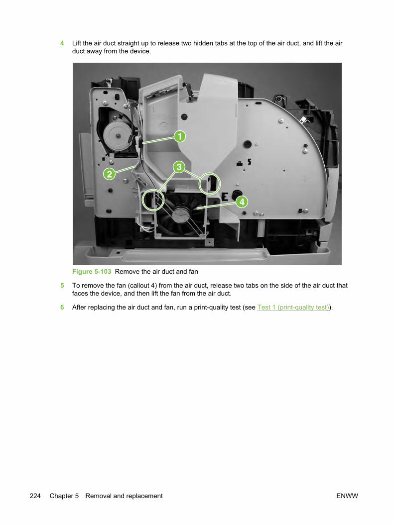
4 Lift the air duct straight up to release two hidden tabs at the top of the air duct, and lift the airduct away from the device.
Figure 5-103 Remove the air duct and fan
5 To remove the fan (callout 4) from the air duct, release two tabs on the side of the air duct thatfaces the device, and then lift the fan from the air duct.
6 After replacing the air duct and fan, run a print-quality test (see Test 1 (print-quality test)).
224 Chapter 5 Removal and replacement ENWW

Printed circuit assemblies (PCAs)Removing the sub-high-voltage transformer PCA1 Remove the power supply cover plate (see Removing the power supply cover plate).
2 Unplug one connector (callout 1) from the high-voltage transformer PCA.
3 Remove two screws (callout 2).
4 Lift up the sub-high-voltage transformer PCA and its holder, and then unplug one connector(callout 3) from the high-voltage transformer PCA.
1
3
2
Figure 5-104 Remove the sub-high-voltage transformer PCA
5 After replacing the sub-high-voltage transformer PCA, run a print-quality test (see Test 1 (print-quality test)) and a copy-quality test (see Test 2 (copy-quality test)).
NOTE If you are servicing an HP Color LaserJet 2840 all-in-one, run a memory-card test(see Test 4 (memory-card test)) as well.
ENWW Printed circuit assemblies (PCAs) 225
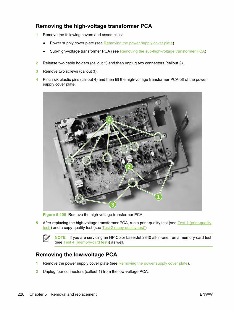
Removing the high-voltage transformer PCA1 Remove the following covers and assemblies:
● Power supply cover plate (see Removing the power supply cover plate)
● Sub-high-voltage transformer PCA (see Removing the sub-high-voltage transformer PCA)
2 Release two cable holders (callout 1) and then unplug two connectors (callout 2).
3 Remove two screws (callout 3).
4 Pinch six plastic pins (callout 4) and then lift the high-voltage transformer PCA off of the powersupply cover plate.
4
31
2
Figure 5-105 Remove the high-voltage transformer PCA
5 After replacing the high-voltage transformer PCA, run a print-quality test (see Test 1 (print-qualitytest)) and a copy-quality test (see Test 2 (copy-quality test)).
NOTE If you are servicing an HP Color LaserJet 2840 all-in-one, run a memory-card test(see Test 4 (memory-card test)) as well.
Removing the low-voltage PCA1 Remove the power supply cover plate (see Removing the power supply cover plate).
2 Unplug four connectors (callout 1) from the low-voltage PCA.
226 Chapter 5 Removal and replacement ENWW
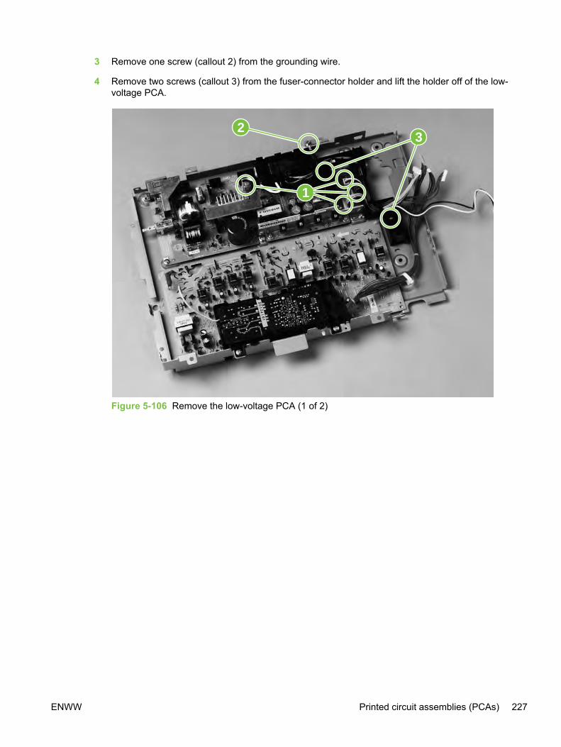
3 Remove one screw (callout 2) from the grounding wire.
4 Remove two screws (callout 3) from the fuser-connector holder and lift the holder off of the low-voltage PCA.
1
32
Figure 5-106 Remove the low-voltage PCA (1 of 2)
ENWW Printed circuit assemblies (PCAs) 227
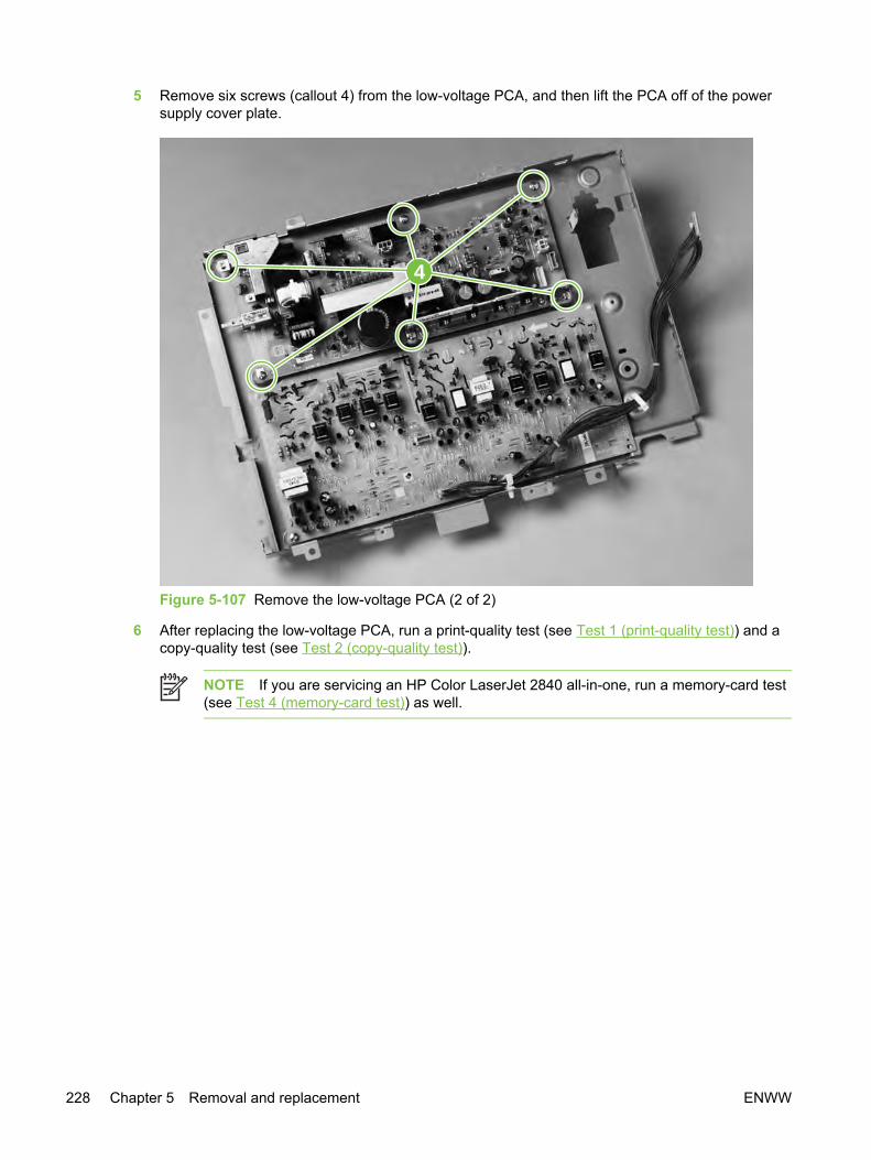
5 Remove six screws (callout 4) from the low-voltage PCA, and then lift the PCA off of the powersupply cover plate.
4
Figure 5-107 Remove the low-voltage PCA (2 of 2)
6 After replacing the low-voltage PCA, run a print-quality test (see Test 1 (print-quality test)) and acopy-quality test (see Test 2 (copy-quality test)).
NOTE If you are servicing an HP Color LaserJet 2840 all-in-one, run a memory-card test(see Test 4 (memory-card test)) as well.
228 Chapter 5 Removal and replacement ENWW
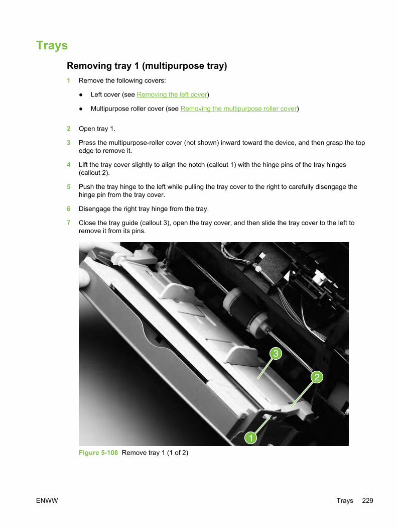
TraysRemoving tray 1 (multipurpose tray)1 Remove the following covers:
● Left cover (see Removing the left cover)
● Multipurpose roller cover (see Removing the multipurpose roller cover)
2 Open tray 1.
3 Press the multipurpose-roller cover (not shown) inward toward the device, and then grasp the topedge to remove it.
4 Lift the tray cover slightly to align the notch (callout 1) with the hinge pins of the tray hinges(callout 2).
5 Push the tray hinge to the left while pulling the tray cover to the right to carefully disengage thehinge pin from the tray cover.
6 Disengage the right tray hinge from the tray.
7 Close the tray guide (callout 3), open the tray cover, and then slide the tray cover to the left toremove it from its pins.
Figure 5-108 Remove tray 1 (1 of 2)
ENWW Trays 229

8 Disengage the left and right hinges from the tray guide and then slide both hinges off of theirkeyed holes (callout 4) in the device.
9 Use needle-nose pliers to unhook two springs (callout 5), one at each side of the tray guide, andthen remove the tray guide.
Figure 5-109 Remove tray 1 (2 of 2)
Reinstallation tip The two springs should remain attached to two pegs inside thedevice. If the springs are not attached, use needle-nose pliers to reattach them beforereinstalling the tray guide.
10 After replacing the multipurpose tray, run a copy-quality test (see Test 2 (copy-quality test)).
Removing optional tray 2 (250-sheet tray)
CAUTION This procedure requires lifting the device. The device is heavy. Hewlett-Packardrecommends that two people lift the device off of tray 2.
1 Remove the right and left covers (see Removing the right cover and Removing the left cover).
230 Chapter 5 Removal and replacement ENWW
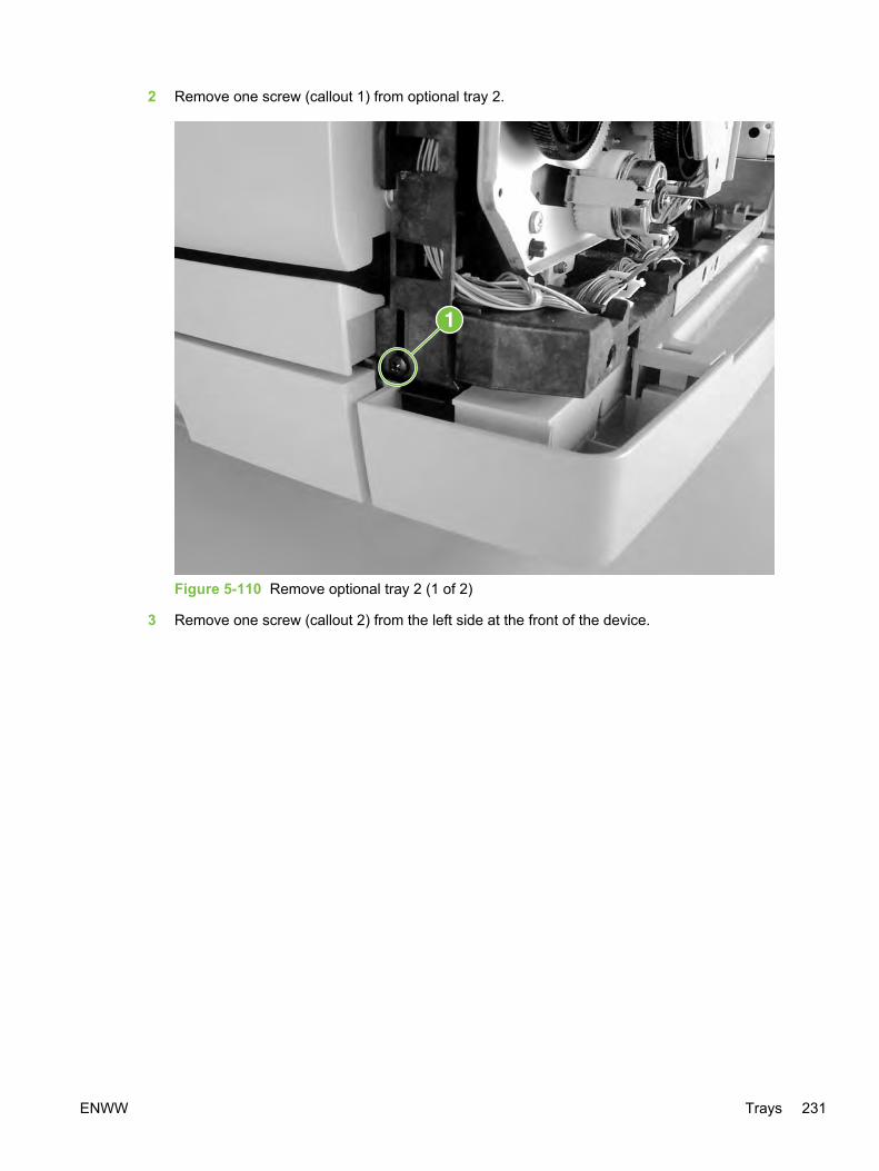
2 Remove one screw (callout 1) from optional tray 2.
Figure 5-110 Remove optional tray 2 (1 of 2)
3 Remove one screw (callout 2) from the left side at the front of the device.
ENWW Trays 231

4 Remove two screws (callout 3) from the back of optional tray 2.
Figure 5-111 Remove optional tray 2 (2 of 2)
232 Chapter 5 Removal and replacement ENWW
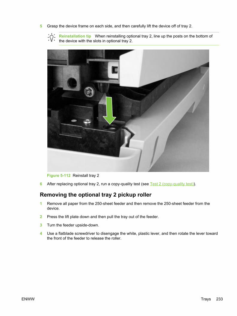
5 Grasp the device frame on each side, and then carefully lift the device off of tray 2.
Reinstallation tip When reinstalling optional tray 2, line up the posts on the bottom ofthe device with the slots in optional tray 2.
Figure 5-112 Reinstall tray 2
6 After replacing optional tray 2, run a copy-quality test (see Test 2 (copy-quality test)).
Removing the optional tray 2 pickup roller1 Remove all paper from the 250-sheet feeder and then remove the 250-sheet feeder from the
device.
2 Press the lift plate down and then pull the tray out of the feeder.
3 Turn the feeder upside-down.
4 Use a flatblade screwdriver to disengage the white, plastic lever, and then rotate the lever towardthe front of the feeder to release the roller.
ENWW Trays 233
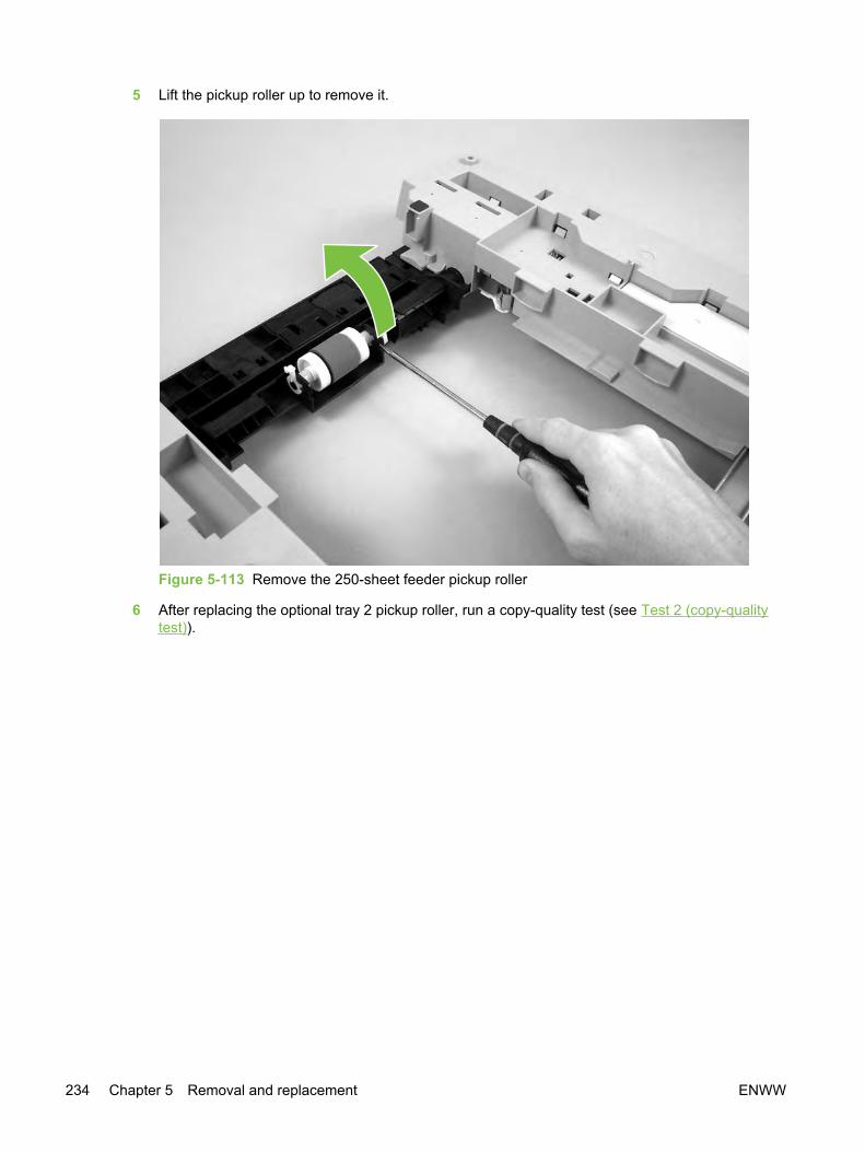
5 Lift the pickup roller up to remove it.
Figure 5-113 Remove the 250-sheet feeder pickup roller
6 After replacing the optional tray 2 pickup roller, run a copy-quality test (see Test 2 (copy-qualitytest)).
234 Chapter 5 Removal and replacement ENWW
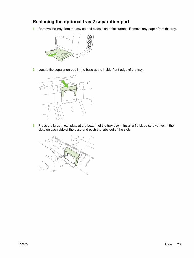
Replacing the optional tray 2 separation pad1 Remove the tray from the device and place it on a flat surface. Remove any paper from the tray.
2 Locate the separation pad in the base at the inside-front edge of the tray.
3 Press the large metal plate at the bottom of the tray down. Insert a flatblade screwdriver in theslots on each side of the base and push the tabs out of the slots.
ENWW Trays 235

4 Pull the separation pad up and out of the tray.
5 Use one hand to position the new separation pad above the empty base. Align the grooves onthe sides of the pad with the sides of the base, and then slide the pad down until the tabs snapinto the slots on the base.
6 Reload any print media, and then slide the tray into the device.
7 After replacing the optional tray 2 separation pad, run a copy-quality test (see Test 2 (copy-quality test)).
236 Chapter 5 Removal and replacement ENWW

6 Troubleshooting
This troubleshooting information is organized to help you resolve printing problems. Choose thegeneral topic or type of problem from the following list.
● Support strategy
● Troubleshooting process
● Control-panel messages
● Clearing jams
● Print problems
● Scan problems
● Copy problems
● Fax problems
● Memory card problems
● Functional tests
● Service-mode functions
● Troubleshooting tools
● Updating or recovering the firmware code
ENWW 237

Support strategyThis device has a one-year limited warranty. Warranty service and support options might varydepending on your country/region. Refer to the support flyer that came in your box for contactinformation, or visit http://www.hp.com.
238 Chapter 6 Troubleshooting ENWW

Troubleshooting processUse the troubleshooting checklist to solve issues with the device.
Troubleshooting checklistFollow the steps below when trying to solve a problem with the device.
NOTE The service CD-ROM contains sound files of normal device operations. Refer tothose files if you are in doubt of what a "normal" device should sound like.
Table 6-1 Troubleshooting checklist
Stepnumber
Verification step Possible problems Solutions
1 Is the power on?
When the device isconnected to agrounded powersource, the controlpanel shows HewlettPackard with movingcursors indicating thatthe firmware code isloading, and the printengine motor rotates forapproximately 45 to 60seconds. When thefirmware is doneloading, Scanner bulbwarming up appears inthe control panel, andthe scan head movesback and forth for 10-15seconds. If you lift thescanner lid, you will seethat the scanner bulb islit. Near the end of thistime, the automaticdocument feeder (ADF)motor turns on for abouttwo seconds.
No power due to failed powersource, cable, switch, or fuse.
1 Verify that the device isplugged in.
2 Verify that the power cable isfunctional and that the powerswitch is on.
3 Check the power source byplugging the device directlyinto the wall or into a differentoutlet.
Print engine motor does not rotate. 1 If the device control panelindicates a jam, verify that thefuser shipping locks havebeen removed.
2 Verify that the rear outputdoor is closed. See To clearoutput area jams.
3 Verify that the print cartridgesand imaging drum areproperly installed. Look at thecontrol-panel messages andfollow the instructions toremove and replace thecartridges.
4 Verify that the top cover isclosed completely.
ADF motor does not rotate. Open the ADF cover and removeany orange shipping tape insidethe ADF.
Verify that the ADF cable isconnected correctly to the scanner.
If the ADF motor still does notrotate, verify that the cables fromthe scanner to the formatter areconnected correctly. See
ENWW Troubleshooting process 239

Stepnumber
Verification step Possible problems Solutions
Removing the scanning assembly.If the problem persists replaceparts in the following order one ata time: the ADF, the scanner, andthen finally the formatter.
Scanner bulb does not light. If the scanner bulb does not light,verify that the cables from thescanner to the formatter areconnected correctly. SeeRemoving the scanning assembly.If the error persists, replace partsone at a time in the followingorder until the problem isresolved: scanner assembly, andfinally the formatter (seeRemoving the formatterassemblies).
2 Does Ready appear inthe device controlpanel?
The control panelshould function withouterror messages.
Control panel shows an error. See Control-panel messages for alist of common messages that willhelp you correct the error.
If no display appears in the controlpanel, verify that the control panelcables are connected correctly.See Removing the control panel.
3 Do information pagesprint?
Print a Configurationpage.
Control panel displays an errormessage.
See Control-panel messages for alist of common messages that willhelp you correct the error.
Media does not move smoothlythrough the device paper path.
Clean the paper path.
Poor print quality. See Print quality problems.
4 Does the device copy?
Place the Configurationpage into the ADF andmake a copy. Thereport should feedsmoothly through theADF, and copies shouldprint without print-quality problems. Makea copy from the flatbedas well.
Poor copy quality from the ADF. 1 If the print quality from theinternal tests and the copyfrom the flatbed wereacceptable, clean the ADFscanning window. See Toclean the scanner glass.
2 If the ADF is damaged,replace the ADF. SeeReplacing the ADF.
Media does not move smoothlythrough the ADF path.
1 Clean the ADF pick roller andADF separation pad.
2 If the problem persists,replace the ADF pickup roller.See Replacing the ADFpickup-roller assembly.
3 If the problem persists,replace the ADF. SeeReplacing the ADF.
Table 6-1 Troubleshooting checklist (continued)
240 Chapter 6 Troubleshooting ENWW
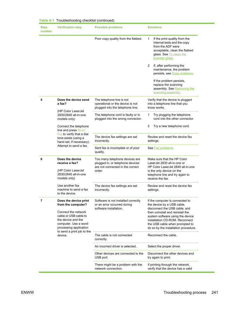
Stepnumber
Verification step Possible problems Solutions
Poor copy quality from the flatbed. 1 If the print quality from theinternal tests and the copyfrom the ADF wereacceptable, clean the flatbedglass. See To clean thescanner glass.
2 If, after performing themaintenance, the problempersists, see Copy problems.
If the problem persists,replace the scanningassembly. See Removing thescanning assembly.
5 Does the device senda fax?
(HP Color LaserJet2830/2840 all-in-onemodels only)
Connect the telephoneline and press START
FAX to verify that a dialtone exists (using ahand set, if necessary).Attempt to send a fax.
The telephone line is notoperational or the device is notplugged into the telephone line.
Verify that the device is pluggedinto a telephone line that youknow works.
The telephone cord is faulty or isplugged into the wrong connector.
1 Try plugging the telephonecord into the other connector.
2 Try a new telephone cord.
The device fax settings are setincorrectly.
Review and reset the device faxsettings.
Sent fax is incomplete or of poorquality.
See Fax problems.
6 Does the devicereceive a fax?
(HP Color LaserJet2830/2840 all-in-onemodels only)
Use another faxmachine to send a faxto the device.
Too many telephone devices areplugged in, or telephone devicesare not connected in the correctorder.
Make sure that the HP ColorLaserJet 2830 all-in-one orHP Color LaserJet 2840 all-in-oneis the only device on thetelephone line and try again toreceive the fax.
The device fax settings are setincorrectly.
Review and reset the device faxsettings.
7 Does the device printfrom the computer?
Connect the networkcable or USB cable tothe device and thecomputer. Use a word-processing applicationto send a print job to thedevice.
Software is not installed correctlyor an error occurred duringsoftware installation.
If the computer is connected tothe device by a USB cable,disconnect the USB cable, andthen uninstall and reinstall thesystem software using the deviceinstallation CD-ROM. Reconnectthe USB cable when prompted todo so by the installation procedure.
The cable is not connectedcorrectly.
Reconnect the cable.
An incorrect driver is selected. Select the proper driver.
Other devices are connected to theUSB port.
Disconnect the other devices andtry again to print.
There might be a problem with thenetwork connection.
If printing through the network,verify that the device has a valid
Table 6-1 Troubleshooting checklist (continued)
ENWW Troubleshooting process 241
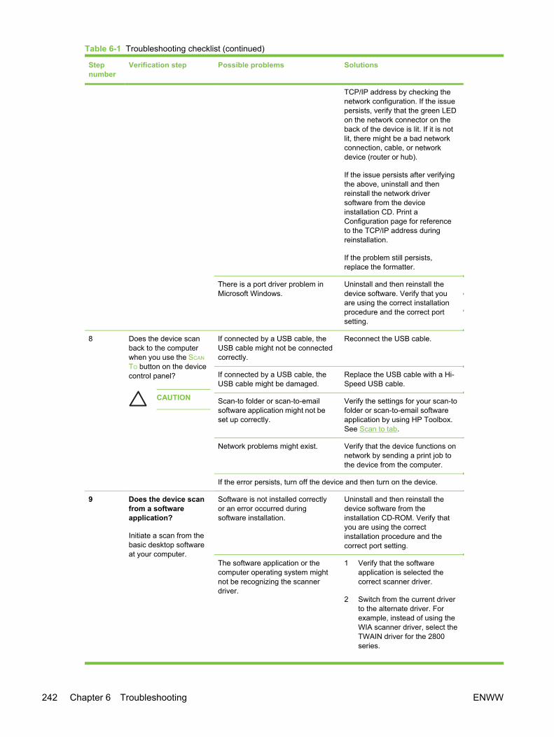
Stepnumber
Verification step Possible problems Solutions
TCP/IP address by checking thenetwork configuration. If the issuepersists, verify that the green LEDon the network connector on theback of the device is lit. If it is notlit, there might be a bad networkconnection, cable, or networkdevice (router or hub).
If the issue persists after verifyingthe above, uninstall and thenreinstall the network driversoftware from the deviceinstallation CD. Print aConfiguration page for referenceto the TCP/IP address duringreinstallation.
If the problem still persists,replace the formatter.
There is a port driver problem inMicrosoft Windows.
Uninstall and then reinstall thedevice software. Verify that youare using the correct installationprocedure and the correct portsetting.
8 Does the device scanback to the computerwhen you use the SCAN
TO button on the devicecontrol panel?
CAUTION
If connected by a USB cable, theUSB cable might not be connectedcorrectly.
Reconnect the USB cable.
If connected by a USB cable, theUSB cable might be damaged.
Replace the USB cable with a Hi-Speed USB cable.
Scan-to folder or scan-to-emailsoftware application might not beset up correctly.
Verify the settings for your scan-tofolder or scan-to-email softwareapplication by using HP Toolbox.See Scan to tab.
Network problems might exist. Verify that the device functions onnetwork by sending a print job tothe device from the computer.
If the error persists, turn off the device and then turn on the device.
9 Does the device scanfrom a softwareapplication?
Initiate a scan from thebasic desktop softwareat your computer.
Software is not installed correctlyor an error occurred duringsoftware installation.
Uninstall and then reinstall thedevice software from theinstallation CD-ROM. Verify thatyou are using the correctinstallation procedure and thecorrect port setting.
The software application or thecomputer operating system mightnot be recognizing the scannerdriver.
1 Verify that the softwareapplication is selected thecorrect scanner driver.
2 Switch from the current driverto the alternate driver. Forexample, instead of using theWIA scanner driver, select theTWAIN driver for the 2800series.
Table 6-1 Troubleshooting checklist (continued)
242 Chapter 6 Troubleshooting ENWW

Stepnumber
Verification step Possible problems Solutions
If the error persists, turn off the device and then turn on the device.
10 Does the devicerecognize and printfrom a memory card?
Insert a memory cardand print an index page.
The device does not recognize thecard.
Remove the card and reinsert itinto the memory-card slot. Verifythat the card is fully inserted intothe slot.
Verify that the memory-card typeis a supported type.
Verify that only one card isinserted in the memory-card slots.
Verify that the memory-cardassembly ribbon cable isconnected correctly to theformatter. See Replacing thememory-card assembly (HP ColorLaserJet 2840 all-in-one only).
If the problem persists withmultiple types of memory cards,replace the following parts one ata time in the following order:memory-card assembly, ribboncable, and then formatter.
The device does not print certainimages.
Verify that the files on the memorycard are in the correct format. Thedevice recognizes only SRGBformat .JPEG files.
Table 6-1 Troubleshooting checklist (continued)
ENWW Troubleshooting process 243
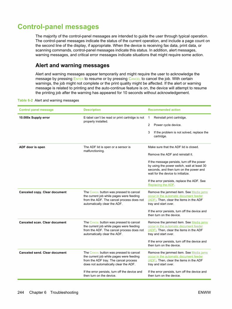
Control-panel messagesThe majority of the control-panel messages are intended to guide the user through typical operation.The control-panel messages indicate the status of the current operation, and include a page count onthe second line of the display, if appropriate. When the device is receiving fax data, print data, orscanning commands, control-panel messages indicate this status. In addition, alert messages,warning messages, and critical error messages indicate situations that might require some action.
Alert and warning messagesAlert and warning messages appear temporarily and might require the user to acknowledge themessage by pressing ENTER to resume or by pressing CANCEL to cancel the job. With certainwarnings, the job might not complete or the print quality might be affected. If the alert or warningmessage is related to printing and the auto-continue feature is on, the device will attempt to resumethe printing job after the warning has appeared for 10 seconds without acknowledgement.
Table 6-2 Alert and warning messages
Control panel message Description Recommended action
10.000x Supply error E-label can’t be read or print cartridge is notproperly installed.
1 Reinstall print cartridge.
2 Power cycle device.
3 If the problem is not solved, replace thecartridge.
ADF door is open The ADF lid is open or a sensor ismalfunctioning.
Make sure that the ADF lid is closed.
Remove the ADF and reinstall it.
If the message persists, turn off the powerby using the power switch, wait at least 30seconds, and then turn on the power andwait for the device to initialize.
If the error persists, replace the ADF. SeeReplacing the ADF.
Canceled copy. Clear document The CANCEL button was pressed to cancelthe current job while pages were feedingfrom the ADF. The cancel process does notautomatically clear the ADF.
Remove the jammed item. See Media jamsoccur in the automatic document feeder(ADF). Then, clear the items in the ADFtray and start over.
If the error persists, turn off the device andthen turn on the device.
Canceled scan. Clear document The CANCEL button was pressed to cancelthe current job while pages were feedingfrom the ADF. The cancel process does notautomatically clear the ADF.
Remove the jammed item. See Media jamsoccur in the automatic document feeder(ADF). Then, clear the items in the ADFtray and start over.
If the error persists, turn off the device andthen turn on the device.
Canceled send. Clear document The CANCEL button was pressed to cancelthe current job while pages were feedingfrom the ADF tray. The cancel processdoes not automatically clear the ADF.
If the error persists, turn off the device andthen turn on the device.
Remove the jammed item. See Media jamsoccur in the automatic document feeder(ADF). Then, clear the items in the ADFtray and start over.
If the error persists, turn off the device andthen turn on the device.
244 Chapter 6 Troubleshooting ENWW

Control panel message Description Recommended action
Card is not fully inserted The memory card has not been fullyinserted.
Verify that the memory card is insertedcompletely.
If the card is fully inserted, try insertinganother memory card.
If more than one memory card type has thesame issue, verify that the LED glows whenthe card inserted. If the LED does not glow,verify that the flat cable that connects thememory-card assembly to the formatter isconnected correctly. See Replacing thememory-card assembly (HP Color LaserJet2840 all-in-one only).
If the issue persists, replace the memory-card assembly.
Comm. error A fax communication error occurredbetween the device and the sender orreceiver.
Allow the device to retry sending the fax.Unplug the device telephone cord from thewall, plug in a telephone, and try making acall. Plug the device phone cord into a jackfor another phone line.
Try a different phone cord.
If the error persists, check the flat flexiblecable between the LIU and the formatter.Reseat or replace the cable. See Removingthe formatter and line interface unit (LIU).
Update the firmware. See Updating orrecovering the firmware code.
If the error persists, replace the LIU. SeeRemoving the formatter and line interfaceunit (LIU).
Device error. [Enter] to cont. An internal error occurred in the device. Press ENTER to resume the job.
If the error persists:
1 Turn off the device and then turn on thedevice.
2 If possible, print the error log from theSecondary service menu, and thentroubleshoot the last error on the list.
3 If the error still persists and you cannotprint an error log, replace thecomponents in the following order: theformatter and then the DC controller.
Device is busy.
Try again later
The device is currently in use. Wait for the device to finish the current job.
If the error persists, turn off the device andthen turn on the device.
Doc feeder jam
Clear, Reload
A piece of media is jammed in the ADF tray. Open the ADF cover, clear the jam, closethe ADF cover, and reload the paper into
Table 6-2 Alert and warning messages (continued)
ENWW Control-panel messages 245

Control panel message Description Recommended action
the ADF tray. See To clear a media jamfrom the automatic document feeder (ADF).
If the error persists, replace the ADFseparation pad (see Removing the ADFseparation pad) and ADF pickup roller (seeReplacing the ADF pickup-roller assembly).
Document feeder mispick. Reload Media in the ADF tray was not picked up. Remove the media from the ADF tray, andthen reload it.
If the error persists, replace the ADFseparation pad (see Removing the ADFseparation pad) and ADF pickup roller (seeReplacing the ADF pickup-roller assembly).
Engine comm. error The device experienced an internalcommunication error.
This is a warning message only. Job outputmight be affected.
If the error persists, turn off the device andthen turn on the device.
Fax delayed – send storage full Fax memory is full. Cancel the fax by pressing ENTER orCANCEL. Resend the fax. You might need tosend the fax in multiple sections if the erroroccurs again.
If the error persists, clear the fax memory:
1 Press MENU, use the < or > button toselect Fax functions, and then pressENTER.
2 Use the < or > button to select Clearsaved faxs, and then press ENTER.
Fax is busy
Canceled send
The fax line to which you were sending afax was busy. The device has canceledsending the fax.
Call the recipient to ensure that the faxmachine is on and ready.
Check that you are dialing the correct faxnumber.
Check that the Redial if busy option isenabled.
Check for a dial tone on the phone line bypressing START FAX.
Make sure that the phone is working bydisconnecting the device, plugging in atelephone to the phone line, and making avoice call.
Plug the device phone cord into a jack foranother phone line, and then try sendingthe fax again.
Try a different phone cord.
If the error persists, check the flat flexiblecable between the LIU and the formatter.Reseat or replace the cable. If the error
Table 6-2 Alert and warning messages (continued)
246 Chapter 6 Troubleshooting ENWW

Control panel message Description Recommended action
persists, replace the LIU. See Removingthe formatter and line interface unit (LIU).
Fax is busy
Redial pending
The fax line to which you were sending afax was busy. The device automaticallyredials the busy number.
Allow the device to retry sending the fax.
Call the recipient to ensure that the faxmachine is on and ready.
Check that you are dialing the correct faxnumber.
Check for a dial tone on the phone line bypressing START FAX.
Make sure that the phone is working bydisconnecting the device, plugging in atelephone to the phone line, and making avoice call.
Plug the device phone cord into a jack foranother phone line, and try sending the faxagain.
Try a different phone cord.
If the error persists, check the flat flexiblecable between the LIU and the formatter.Reseat or replace the cable. If the errorpersists, replace the LIU. See Removingthe formatter and line interface unit (LIU).
Fax memory full
Canceling recv.
During the fax transmission, the device ranout of memory. Only the pages that fit intomemory will be printed.
Print all of the faxes and have the senderresend the fax. Cancel all fax jobs or clearthe faxes from memory.
NOTE Adding a memory DIMMdoes not help resolve this issue.
Fax memory full
Canceling send
During the fax job, the memory filled. Allpages of the fax have to be in memory for afax job to work correctly. Only the pagesthat fit into memory were sent.
Print all received faxes or wait until allpending faxes are sent.
Ask the sender to send the fax again.
Cancel all fax jobs or clear the faxes frommemory.
Fax recv. error An error occurred while trying to receive afax.
Ask the sender to resend the fax.
Try faxing back to the sender or another faxmachine.
Check for a dial tone on the phone line bypressing START FAX.
Check that the telephone cord is securelyconnected by unplugging and repluggingthe cord.
Make sure that you are using the telephonecord that came with the device.
Table 6-2 Alert and warning messages (continued)
ENWW Control-panel messages 247

Control panel message Description Recommended action
Make sure that the phone is working bydisconnecting the device, plugging in atelephone to the phone line, and making avoice call.
Make sure that the telephone cordconnects the device directly to the wall jack.Remove any third-party devices, such asan answering machine, that are connectedbetween the device and the wall jack.
Turn off error-correction mode (ECM), andturn off V.34. Ask the sender to resend thefax.
Connect the device to a different phone line.
If the error persists, check the flat flexiblecable between the LIU and the formatter.Reseat or replace the cable. If the errorpersists, replace the LIU. See Removingthe formatter and line interface unit (LIU).
Fax Send error An error occurred while trying to send a fax. Try resending the fax.
Try faxing to another fax number.
Check for a dial tone on the phone line bypressing START FAX.
Check that the telephone cord is securelyconnected by unplugging and repluggingthe cord.
Make sure that you are using the telephonecord that came with the device.
Make sure that the phone is working bydisconnecting the device, plugging in atelephone to the phone line, and making avoice call.
Make sure that the telephone cordconnects the device directly to the wall jack.Remove any third-party devices, such asan answering machine, that are connectedbetween the device and the wall jack.
Connect the device to a different phone line.
Set the fax resolution to Standard insteadof the default of Fine.
If the error persists, check the flat flexiblecable between the LIU and the formatter.Reseat or replace the cable. If the errorpersists, replace the LIU. See Removingthe formatter and line interface unit (LIU).
Fit to Page on
flatbed only
The copy reduce/enlarge feature (called"Fit to Page") applies only to copies madefrom the flatbed scanner.
Use the flatbed or select another reduction/enlargement setting.
Table 6-2 Alert and warning messages (continued)
248 Chapter 6 Troubleshooting ENWW
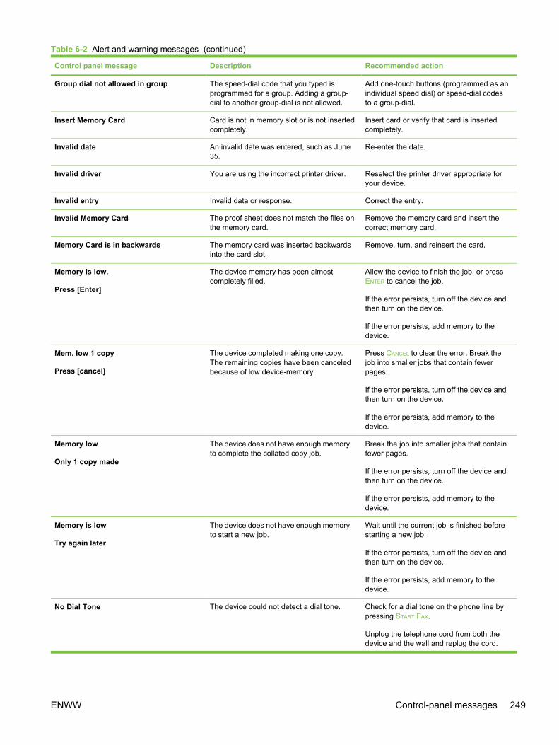
Control panel message Description Recommended action
Group dial not allowed in group The speed-dial code that you typed isprogrammed for a group. Adding a group-dial to another group-dial is not allowed.
Add one-touch buttons (programmed as anindividual speed dial) or speed-dial codesto a group-dial.
Insert Memory Card Card is not in memory slot or is not insertedcompletely.
Insert card or verify that card is insertedcompletely.
Invalid date An invalid date was entered, such as June35.
Re-enter the date.
Invalid driver You are using the incorrect printer driver. Reselect the printer driver appropriate foryour device.
Invalid entry Invalid data or response. Correct the entry.
Invalid Memory Card The proof sheet does not match the files onthe memory card.
Remove the memory card and insert thecorrect memory card.
Memory Card is in backwards The memory card was inserted backwardsinto the card slot.
Remove, turn, and reinsert the card.
Memory is low.
Press [Enter]
The device memory has been almostcompletely filled.
Allow the device to finish the job, or pressENTER to cancel the job.
If the error persists, turn off the device andthen turn on the device.
If the error persists, add memory to thedevice.
Mem. low 1 copy
Press [cancel]
The device completed making one copy.The remaining copies have been canceledbecause of low device-memory.
Press CANCEL to clear the error. Break thejob into smaller jobs that contain fewerpages.
If the error persists, turn off the device andthen turn on the device.
If the error persists, add memory to thedevice.
Memory low
Only 1 copy made
The device does not have enough memoryto complete the collated copy job.
Break the job into smaller jobs that containfewer pages.
If the error persists, turn off the device andthen turn on the device.
If the error persists, add memory to thedevice.
Memory is low
Try again later
The device does not have enough memoryto start a new job.
Wait until the current job is finished beforestarting a new job.
If the error persists, turn off the device andthen turn on the device.
If the error persists, add memory to thedevice.
No Dial Tone The device could not detect a dial tone. Check for a dial tone on the phone line bypressing START FAX.
Unplug the telephone cord from both thedevice and the wall and replug the cord.
Table 6-2 Alert and warning messages (continued)
ENWW Control-panel messages 249

Control panel message Description Recommended action
Make sure that you are using the telephonecord that came with the device.
Unplug the device telephone cord from thewall, plug in a telephone, and try making avoice call.
Plug the device telephone cord into a jackfor another phone line.
Make sure that the telephone cordconnects the device directly to the wall jack.Remove any third-party devices, such asan answering machine, that are connectedbetween the device and the wall jack.
Update the firmware. See Updating orrecovering the firmware code.
If the error persists, check the flat flexiblecable between the LIU and the formatter.Reseat or replace the cable. If the errorpersists, replace the LIU. See Removingthe formatter and line interface unit (LIU).
No document sent The device did not scan any pages, or it didnot receive any pages from the computer totransmit a fax.
Try sending the fax again.
No fax answer.
Canceled send
Attempts to redial a fax number failed, orthe “Redial-no answer” option was turned off.
Call the recipient to ensure that the faxmachine is on and ready.
Check that you are dialing the correct faxnumber.
Check that the redial option is enabled.
Unplug the telephone cord from both thedevice and the wall and replug the cord.
Unplug the device telephone cord from thewall, plug in a telephone, and try making avoice call.
Plug the device phone cord into a jack foranother phone line.
Make sure that the telephone cordconnects the device directly to the wall jack.Remove any third-party devices, such asan answering machine, that are connectedbetween the device and the wall jack.
If the error persists, check the flat flexiblecable between the LIU and the formatter.Reseat or replace the cable. If the errorpersists, replace the LIU. See Removingthe formatter and line interface unit (LIU).
No fax answer
Redial pending
The receiving fax line did not answer. Thedevice attempts to redial after a few minutes.
Allow the device to retry sending the fax.
Call the recipient to ensure that the faxmachine is on and ready.
Table 6-2 Alert and warning messages (continued)
250 Chapter 6 Troubleshooting ENWW

Control panel message Description Recommended action
Check that you are dialing the correct faxnumber.
If the device continues to redial, unplug thedevice telephone cord from the wall, plug ina telephone, and try making a voice call.
Plug the device phone cord into a jack foranother phone line.
Try a different phone cord.
Make sure that the telephone cordconnects the device directly to the wall jack.Remove any third-party devices, such asan answering machine, that are connectedbetween the device and the wall jack.
If the error persists, check the flat flexiblecable between the LIU and the formatter.Reseat or replace the cable. If the errorpersists, replace the LIU. See Removingthe formatter and line interface unit (LIU).
No fax detected The device answered the incoming call butdid not detect that a fax machine was calling.
Allow the device to retry receiving the fax.
Try a different phone cord.
Plug the device phone cord into a jack foranother phone line.
Make sure that the telephone cordconnects the device directly to the wall jack.Remove any third-party devices, such asan answering machine, that are connectedbetween the device and the wall jack.
If the error persists, check the flat flexiblecable between the LIU and the formatter.Reseat or replace the cable. If the errorpersists, replace the LIU. See Removingthe formatter and line interface unit (LIU).
No image layout selected An image layout might not be selected onthe proof sheet.
Verify that you have marked one of thebubbles corresponding to an image layout.
No images selected You might not have selected any images onthe proof sheet.
Verify that you have marked the bubblesunderneath the images you want to print.
No paper pickup
[Enter] to cont.
The print engine has failed to pick up apiece of media.
In tray 1, verify that the media was insertedfar enough into the tray. In optional tray 2,verify that the paper-length guide is in thecorrect position for the media size that youare using.
Reload the media in the input tray andpress ENTER to continue the job.
If the error persists, replace the pickuproller. See Replacing the tray 1 pickup rollerand separation pad.
No paper type selected A paper type might not be selected on theproof sheet.
Verify that you have marked one of thebubbles corresponding to a paper type.
Table 6-2 Alert and warning messages (continued)
ENWW Control-panel messages 251
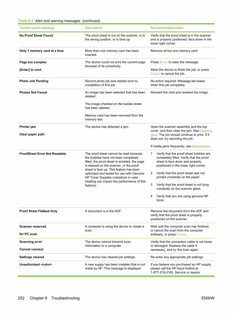
Control panel message Description Recommended action
No Proof Sheet Found The proof sheet is not on the scanner, is inthe wrong position, or is face up.
Verify that the proof sheet is in the scannerand is properly positioned, face down in thelower right corner.
Only 1 memory card at a time More than one memory card has beeninserted.
Remove all but one memory card.
Page too complex
[Enter] to cont.
The device could not print the current pagebecause of its complexity.
Press ENTER to clear the message.
Allow the device to finish the job, or pressCANCEL to cancel the job.
Photo Job Pending Second photo job was started prior tocompletion of first job.
No action required. Message will ceasewhen first job completes.
Photos Not Found An image has been selected that has beendeleted.
The image checked on the bubble sheethas been deleted.
Memory card has been removed from thememory slot.
Reinsert the card and reselect the image.
Printer jam
Clear paper path
The device has detected a jam. Open the scanner assembly and the topcover, and then clear the jam. See Clearingjams. The job should continue to print. If itdoes not, try reprinting the job.
If media jams frequently, see Maintenance.
ProofSheet Error Not Readable The proof sheet cannot be read becausethe bubbles have not been completelyfilled, the proof sheet is wrinkled, the pageis skewed on the scanner, or the proofsheet is face up. This feature has beenoptimized and tested for use with GenuineHP Toner Supplies (variations in colorshading can impact the performance of thisfeature).
1 Verify that the proof sheet bubbles arecompletely filled. Verify that the proofsheet is face down and properlypositioned in the lower right corner.
2 Verify that the proof sheet was notprinted crookedly on the paper.
3 Verify that the proof sheet is not lyingcrookedly on the scanner glass.
4 Verify that you are using genuine HPtoner.
Proof Sheet Flatbed Only A document is in the ADF. Remove the document from the ADF andverify that the proof sheet is properlypositioned on the scanner.
Scanner reserved
for PC scan
A computer is using the device to create ascan.
Wait until the computer scan has finished,or cancel the scan from the computersoftware, or press CANCEL.
Scanning error
Cannot connect
The device cannot transmit scaninformation to a computer.
Verify that the connection cable is not looseor damaged. Replace the cable ifnecessary, and try the scan again.
Settings cleared The device has cleared job settings. Re-enter any appropriate job settings.
Unauthorized <color> A new supply has been installed that is notmade by HP. This message is displayed
If you believe you purchased an HP supply,please call the HP fraud hotline at1-877-219-3183. Service or repairs
Table 6-2 Alert and warning messages (continued)
252 Chapter 6 Troubleshooting ENWW

Control panel message Description Recommended action
until an HP supply is installed or ENTER ispressed.
required as a result of using non-HP supplies is not covered underHP warranty.
To continue printing, press ENTER. The firstpending job will be cancelled.
Unknown Memory Card Error There is an issue with either the memorycard or the device memory-card reader.
Reinsert the card. If the error persists,insert a different card.
Unsupported Memory Card The memory card that you have inserted isnot a type that is supported.
Insert a card that is supported. TheHP Color LaserJet 2840 all-in-one supportsthe following cards:
■ CompactFlash
■ Ultra CompactFlash
■ Smart Media
■ Memory Stick
■ Secure Digital
■ Multi Media Card
■ XD Card
Critical error messagesCritical error messages can indicate some kind of failure. Cycling the power might fix the problem. Ifa critical error persists, the device might require service.
Table 6-3 Critical error messages
Control panel message Description Recommended action
50.x Fuser Error The device has experienced an internalhardware error.
Turn off the device, and then disconnectthe power cord. Remove the fuser (see Toclear output area jams), and then wait atleast 20 minutes. Reinstall the fuser, turnon the device, and then wait for the deviceto initialize.
CAUTION The parts on theinternal surface of the fuser arevery hot. To avoid burning yourself,do not touch those parts.
Perform the heating-element check. SeeHeating element test. If the error persists,replace the fuser assembly. See Replacingthe fuser assembly.
If, after replacing the fuser assembly, theerror persists, replace the power supply.See Removing the power supply cover plate.
Table 6-2 Alert and warning messages (continued)
ENWW Control-panel messages 253

Control panel message Description Recommended action
51 Laser Error The device has experienced an internalhardware error.
Turn off the power by using the powerswitch, wait at least 30 seconds, and thenturn on the power and wait for the device toinitialize.
If the error persists, replace the laser/scanner assembly. See Removing the laser/scanner assembly.
52 Scanner Error The device has experienced an internalhardware error.
Turn off the power by using the powerswitch, wait at least 30 seconds, and thenturn on the power and wait for the device toinitialize.
If the error persists, replace the scanningassembly. See Removing the scanningassembly.
54.2, 55.1, 59.16, 59.192, 59.4, 59.99 Errors The device has experienced an internalhardware error.
Turn off the power by using the powerswitch, wait at least 30 seconds, and thenturn on the power and wait for the device toinitialize.
54.2—Carousel rotation error: Replacethe carousel drive motor (see Removing thecarousel-engagement motor). If the errorpersists, replace the DC controller (seeRemoving the DC controller). If the errorstill persists, inspect or replace theengaging detection flag.
55.1—DC controller Memory Error:Replace the DC controller. See Removingthe DC controller.
59.16—Main Motor rotation error: Checkthe cable connections to the DC controller.If the error persists, replace the DCcontroller (seeRemoving the DCcontroller ). If the error still persists, replacethe main motor.
59.192—Developer Motor rotation error:Check the cable connections to the DCcontroller. If the error persists, replace theDC controller (seeRemoving the DCcontroller ). If the error still persists, replacethe developer motor.
59.4—Fuser motor error: Verify that thefuser is seated completely. If the errorpersists, replace the fuser motor. If theerror still persists, replace the DC controller(seeRemoving the DC controller ).
59.99—T2 Clutch error: Check the cableconnections to the DC controller. If the errorpersists, remove the imaging drum andcheck the clutch. If the error persists,replace the T2 clutch. If the error stillpersists, replace the DC controller(seeRemoving the DC controller ).
Table 6-3 Critical error messages (continued)
254 Chapter 6 Troubleshooting ENWW

Control panel message Description Recommended action
57 Fan Error
Turn off then on
The device has experienced a problem withits internal fan.
Turn off the power by using the powerswitch, wait at least 30 seconds, and thenturn on the power and wait for the device toinitialize.
If the error persists, replace the fan. SeeRemoving the air duct and fan.
If the error still persists, replace the DCcontroller. See Removing the DC controller.
79 Error
Turn off then on
The device has experienced an internalfirmware error.
Turn off the power by using the powerswitch, wait at least 30 seconds, and thenturn on the power and wait for the device toinitialize.
If you have recently installed a memoryDIMM in the device, turn off the device,remove the memory DIMM, reinstall theDIMM to verify that it is seated properly,and then turn on the device.
If a surge protector is being used, removeit. Plug the device directly into the wallsocket. Use the power switch to turn thedevice on.
If the error persists, upgrade the firmware.See Updating or recovering the firmwarecode.
If the error persists, replace the formatter.See Removing the formatter assemblies.
Engine error The device has experienced an engine error. Turn off the power by using the powerswitch, wait at least 30 seconds, and thenturn on the power and wait for the device toinitialize.
Sensor error The device has experienced an internalsensor error (most likely, the top-of-pagesensor).
Turn off the power by using the powerswitch, wait at least 30 seconds, and thenturn on the power and wait for the device toinitialize.
If the error persists, check the top-of-pagesensor. See Removing the density sensorand top-of-page sensor.
If the error persists, replace the DCcontroller. See Removing the DC controller.
Table 6-3 Critical error messages (continued)
ENWW Control-panel messages 255

Clearing jamsThis section contains instructions for clearing jams from the device.
Media jams occur in the deviceOccasionally, paper or other print media can become jammed during a print job. Some causesinclude the following events:
■ The input trays are loaded improperly or overfilled, or the media guides are not set properly.
■ Optional tray 2 is removed during a print job.
■ The top cover is opened during a print job.
■ Too many sheets have accumulated in an output area, or sheets are blocking an output area.The top output bin should contain no more than 125 sheets. With the rear output door, pagesshould be removed as soon as they exit the device.
■ The print media that is being used does not meet HP specifications. See Media specifications.
■ The media is damaged or has foreign objects attached to it, such as staples or paper clips.
■ The environment in which the print media was stored is too humid or too dry. See Printing andstorage environment.
Tips to avoid media jams ■ Verify that the input tray is not overfilled. The input tray capacity varies depending on the type of
print media that you are using.
■ Verify that the media guides are properly adjusted.
■ Check that the input tray is securely in place.
■ Do not add print media into the input tray while the device is printing.
■ Use only HP-recommended media types and sizes. See Media specifications for moreinformation about print media types.
■ Do not let print media stack up in the output bin. The print media type and the amount of tonerused affect the output bin capacity.
■ Check the power connection. Make sure that the power cord is firmly connected to both thedevice and the power supply box. Plug the power cord into a grounded AC power outlet.
Where to look for jamsJams can occur in these locations:
■ Inside the device—under the imaging drum or along the internal paper path
■ In output areas—either the top output bin or the rear output door
■ In the automatic document feeder (ADF)
256 Chapter 6 Troubleshooting ENWW
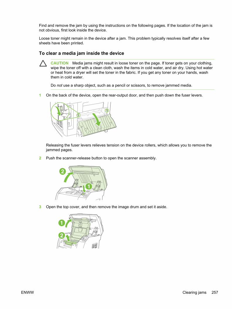
Find and remove the jam by using the instructions on the following pages. If the location of the jam isnot obvious, first look inside the device.
Loose toner might remain in the device after a jam. This problem typically resolves itself after a fewsheets have been printed.
To clear a media jam inside the device
CAUTION Media jams might result in loose toner on the page. If toner gets on your clothing,wipe the toner off with a clean cloth, wash the items in cold water, and air dry. Using hot wateror heat from a dryer will set the toner in the fabric. If you get any toner on your hands, washthem in cold water.
Do not use a sharp object, such as a pencil or scissors, to remove jammed media.
1 On the back of the device, open the rear-output door, and then push down the fuser levers.
Releasing the fuser levers relieves tension on the device rollers, which allows you to remove thejammed pages.
2 Push the scanner-release button to open the scanner assembly.
3 Open the top cover, and then remove the image drum and set it aside.
ENWW Clearing jams 257

4 With both hands, grasp the side of the media that is most visible (this includes the middle), andcarefully pull it free from the device.
5 When you have removed the jammed media, replace the image drum, and close the top coverand the scanner assembly.
6 Close the rear output door to return the fuser levers to their original upward position.
After clearing the media jam, you might need to turn the device off, and then turn it on again.
NOTE When you add new media, remove all of the media from the input tray, straighten thestack after adding the new media, place the stack in the tray, and then adjust the media guides.
To clear output area jamsIf the media has jammed where it exits the device, complete the following steps.
CAUTION Do not use a sharp object, such as a pencil or scissors, to remove jammed media.
1 On the back of the device, open the rear-output door, and then push down the fuser levers.
Releasing the fuser levers relieves tension on the device rollers, which allows you to remove thejammed pages.
258 Chapter 6 Troubleshooting ENWW
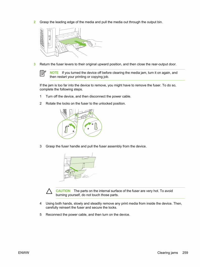
2 Grasp the leading edge of the media and pull the media out through the output bin.
3 Return the fuser levers to their original upward position, and then close the rear-output door.
NOTE If you turned the device off before clearing the media jam, turn it on again, andthen restart your printing or copying job.
If the jam is too far into the device to remove, you might have to remove the fuser. To do so,complete the following steps.
1 Turn off the device, and then disconnect the power cable.
2 Rotate the locks on the fuser to the unlocked position.
3 Grasp the fuser handle and pull the fuser assembly from the device.
CAUTION The parts on the internal surface of the fuser are very hot. To avoidburning yourself, do not touch those parts.
4 Using both hands, slowly and steadily remove any print media from inside the device. Then,carefully reinsert the fuser and secure the locks.
5 Reconnect the power cable, and then turn on the device.
ENWW Clearing jams 259

Media jams occur in the automatic document feeder (ADF)Occasionally, media becomes jammed during a copy, scan, or fax job.
You are notified of a media jam by the Doc feeder jam Clear, Reload message that appears on thedevice control-panel display. Possible problems include the following:
■ The ADF input tray is loaded incorrectly or is too full. See Loading documents to scan for moreinformation.
■ The media does not meet HP specifications, such as those for size or type. See Mediaspecifications for more information.
■ The media is not of good quality. If it is not free of cuts, nicks, tears, spots, loose particles, dust,wrinkles, voids, staples, paper clips and curled or bent edges, replace it.
To clear a media jam from the automatic document feeder (ADF)1 Open the ADF cover.
NOTE Verify that any shipping tape inside the ADF has been removed.
2 Remove the jam cleanout part. Using both hands, lift up on the two handles until the partunsnaps. Rotate and lift out the cleanout part and set it aside.
3 Lifting the green lever, rotate the pick mechanism until it stays open.
260 Chapter 6 Troubleshooting ENWW
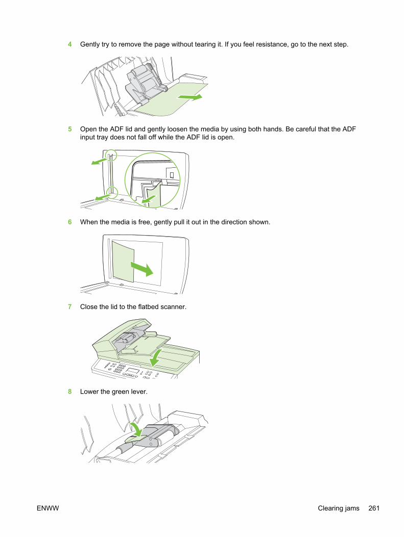
4 Gently try to remove the page without tearing it. If you feel resistance, go to the next step.
5 Open the ADF lid and gently loosen the media by using both hands. Be careful that the ADFinput tray does not fall off while the ADF lid is open.
6 When the media is free, gently pull it out in the direction shown.
7 Close the lid to the flatbed scanner.
8 Lower the green lever.
ENWW Clearing jams 261

9 Reinstall the cleanout part by inserting it as shown. Push down on the two tabs until the partsnaps into place. Install the cleanout part correctly, because future jamming might occur if thecleanout part is not replaced correctly.
10 Close the ADF lid.
262 Chapter 6 Troubleshooting ENWW

Print problemsPrint quality problemsOccasionally, you might encounter problems with print quality. The information in the followingsections helps you identify and resolve these issues.
NOTE If you are having copy problems, see Copy problems.
Improving print qualityUse the print-quality settings to prevent print-quality problems.
Understanding print-quality settings
Print-quality settings affect how light or dark the print is on the page and the style in which thegraphics are printed. You can also use the print-quality settings to optimize the print quality for aspecific media type.
You can change the settings in the device properties to accommodate the types of jobs that you areprinting.
To temporarily change print-quality settings
To change the print-quality settings only for the current software program, open the propertiesthrough the Print Setup menu in the program that you are using to print.
To change print-quality settings for all future jobs
NOTE For Macintosh instructions, see the device user guide for more information.
For Windows 98, Windows 2000, and Windows Me:
1 In the Windows system tray, click Start, select Settings, and then click Printers.
2 Right-click the device icon.
3 Click Properties (in Windows 2000, you can also click Printing Preferences).
4 Change the settings, and click OK.
For Windows XP (corporate version):
1 In the Windows system tray, click Start, and then click Printers and Faxes.
2 Right-click the device icon.
3 Click Properties, or click Printing Preferences.
4 Change the settings, and click OK.
Identifying and correcting print defectsUse the checklist and print-quality issues charts in this section to solve print-quality problems.
ENWW Print problems 263

Print-quality checklist
General print-quality problems can be solved by using the following checklist:
1 Make sure that the paper or print media that you are using meets specifications. See Mediaspecifications. Generally, smoother paper provides better results.
Some paper reams are marked with an arrow on the label that indicates the smooth side of thepaper. Make sure that you are printing on the side indicated.
2 If you are using a special print media such as labels, transparencies, glossy, or letterhead,ensure that you have printed by type.
3 Print a Configuration page and Supplies Status page at the device.
● Check the Supplies Status page to see if any supplies are low or empty. No information isprovided for non-HP print cartridges.
● If the pages do not print correctly, the problem is with the hardware.
To determine the hardware problem, lightly press the switch in the upper left corner of theopen multipurpose tray, toward the rear of the device frame, with at least three sheets ofpaper in the multipurpose tray. The device should print a sheet with horizontal lines of all fourcolors. If one or more colors are missing, inspect the device imaging system. If all colors areprinted, troubleshoot for a formatter issue.
4 Print a Demo page from HP Toolbox. If the page prints, the problem is with the printer driver. Tryprinting from the other printer driver. For example, if you are using the PCL 6 printer driver, printfrom the PS printer driver.
● Use the Add Printer Wizard in the Printers (or Printers and Faxes in Windows XP) dialogbox to install the PS driver.
5 Try printing from a different program. If the page prints correctly, the problem is with the programfrom which you were printing.
6 Restart the computer and the device and try printing again. If the problem is not resolved, chooseone of these options:
● If you suspect the problem is with the engine print and paper path, perform an engine test.See Engine test.
● If the problem is affecting all printed pages, see General print quality issues.
● If the problem is affecting only pages printed in color, see Solving issues with color documents.
264 Chapter 6 Troubleshooting ENWW

General print quality issues
The following examples depict letter-size paper that has passed through the device short edge first.These examples illustrate problems that would affect all of the pages that you print, whether you printin color or in black only. The topics that follow list the typical cause and solution for each of theseexamples.
Problem Cause Solution
Print is light or faded. The media might not meetHP specifications.
Use media that meetsHP specifications. See Mediaspecifications.
One or more print cartridges might below. If you are using non-HP printcartridges, no messages appear on thedevice control panel or in HP Toolbox.
Replace any low print cartridges. SeeReplacing the print cartridges.
If you are using non-HP printcartridges, replace them with HPcartridges.
If none of the print cartridges or theimaging drum is low or empty, removethe print cartridges one at a time andinspect the toner roller in each to see ifthe roller is damaged. If so, replace theprint cartridge.
The imaging drum might be low ordamaged.
Print the Supplies Status page to checkthe remaining life, and verify that theimaging drum has not been exposed tolight for a long period of time. Replacethe imaging drum if it is low ordamaged. See Replacing the imagingdrum.
The device might not be calibratedcorrectly.
Calibrate the device. See Printercalibration.
If the light printing is on the left side ofthe page, the carousel might bedislocated.
Verify that the print-cartridge carouseldrive teeth are aligned correctly. If theteeth are aligned correctly, replace theprint-cartridge carousel. See Removingthe print-cartridge carousel.
Toner specks appear. The media might not meetHP specifications.
Use media that meetsHP specifications. See Mediaspecifications.
The paper path might need cleaning. Clean the paper path. See Cleaningthe paper path, or see the HP Toolboxonline Help.
Dropouts appear. A single sheet of print media might bedefective.
Try reprinting the job.
The moisture content of the paper isuneven or the paper has moist spotson its surface.
Try different paper, such as high-quality paper that is intended for colorlaser printers. See Media specifications.
ENWW Print problems 265

Problem Cause Solution
The paper lot is flawed. Themanufacturing processes can causesome areas to reject toner.
Try different paper, such as high-quality paper that is intended for colorlaser printers. See Media specifications.
The imaging drum might be defective. Replace the imaging drum. SeeReplacing the imaging drum.
Vertical streaks or bands appear on thepage.
One or more print cartridges might below or defective. If you are using non-HP print cartridges, no messagesappear on the device control panel orin the HP Toolbox.
Replace any low print cartridges. SeeReplacing the print cartridges.
If the error occurs during copy jobsonly, the scanner glass of the ADFwindow might be dirty.
Clean the scanner glass and the ADFwindow. See .
The imaging drum might be low. Replace the imaging drum. SeeReplacing the imaging drum.
The amount of background tonershading becomes unacceptable.
The media might not meetHP specifications.
Use a different paper with a lighterbasis weight. See Media specifications.
Very dry (low humidity) conditions canincrease the amount of backgroundshading.
Check the device environment.
One or more print cartridges might below. If you are using non-HP printcartridges, no messages appear on thedevice control panel or in theHP Toolbox.
Replace any low print cartridges. SeeReplacing the print cartridges.
The imaging drum might be low. Replace the imaging drum. SeeReplacing the imaging drum.
Toner smears appear on the media. The media might not meetHP specifications.
Use media that meetsHP specifications. See Mediaspecifications.
If toner smears appear on the leadingedge of the paper, the media guidesare dirty, or debris has accumulated inthe print path.
Clean the media guides and the paperpath. See Cleaning the paper path.
The imaging drum might be low. Replace the imaging drum. SeeReplacing the imaging drum.
266 Chapter 6 Troubleshooting ENWW

Problem Cause Solution
Media might be jammed in the imagingdrum.
Complete the following steps to clearthe jam:
1 Remove the imaging drum fromthe device. See Replacing theimaging drum.
2 Rotate the black dial (jamclearance door lock), located onthe top, left-hand side of theimaging drum, counterclockwise.
3 Lift upward to open the black jamclearance door near the greenhandle on the top of the imagingdrum.
4 Remove the media from inside theimaging drum.
NOTE Do not touch thewhite sleeve in theimaging drum whenremoving the media, asfingerprints will cause print-quality issues. Ifnecessary, use a lint-freecloth to gently wipe anyfingerprints off the whitesleeve.
5 Close the jam clearance door, andthen rotate the locking mechanismclockwise.
6 Reinstall the imaging drum in thedevice.
The toner smears easily when touched. The device is not set to print on thetype of media on which you want toprint.
In the printer driver, select the Papertab and set Type is to match the typeof media on which you are printing.Print speed might be slower if you areusing heavy paper.
The media might not meetHP specifications.
Use media that meetsHP specifications. See Mediaspecifications.
The paper path might need cleaning. Clean the device. See Cleaning thedevice.
If the error persists, verify that the fuser is working correctly. If it is not workingcorrectly, replace the fuser. See Removing the formatter assemblies. If the errorstill persists, replace the DC controller. See Removing the DC controller.
Marks repeatedly appear at evenintervals on the printed side of the page.
The device is not set to print on thetype of media on which you want toprint.
In the printer driver, select the Papertab and set Type is to match the typeof paper on which you are printing.Print speed might be slower if you areusing heavy paper.
ENWW Print problems 267

Problem Cause Solution
Internal parts might have toner on them. The problem typically corrects itselfafter a few more pages. Run a cleaningpage through the device. See Cleaningthe device.
The paper path might need cleaning. Run a cleaning page through thedevice. See Cleaning the device.
The imaging drum might be low. Replace the imaging drum. SeeReplacing the imaging drum.
The fuser might be damaged. Replace the fuser. See Replacing thefuser assembly.
Marks repeatedly appear at evenintervals on the unprinted side of thepage.
Internal parts might have toner on them. The problem typically corrects itselfafter a few more pages. Run a cleaningpage through the device. See Cleaningthe device.
The paper path might need cleaning. Run a cleaning page through thedevice. See Cleaning the device.
The imaging drum might be low. Replace the imaging drum. SeeReplacing the imaging drum.
The fuser might be damaged. Replace the fuser. See Replacing thefuser assembly.
The printed page contains misformedcharacters.
The media might not meetHP specifications.
Use a different paper, such as high-quality paper that is intended for colorlaser printers. See Media specifications.
If characters are incorrectly formed sothat they produce a wavy effect, thelaser/scanner assembly might needservice.
Verify that the problem also occurs onthe Configuration page. If so, replacethe laser/scanner assembly. SeeRemoving the laser/scanner assembly.
The printed page is curled or wavy. The device is not set to print on thetype of media on which you want toprint.
In the printer driver, select the Papertab and set Type is to match the typeof paper on which you are printing.Print speed might be slower if you areusing heavy paper.
The paper path is curling the media. Open the rear output door to print tothe straight-through paper path.
The media might not meetHP specifications.
Use a different paper, such as high-quality paper that is intended for colorlaser printers. See Media specifications.
Both high temperature and humiditycan cause paper curl.
Check the device environment.
Text or graphics are skewed on theprinted page.
The media might be loaded incorrectly. Make sure that the paper or other printmedia is loaded correctly and that the
268 Chapter 6 Troubleshooting ENWW

Problem Cause Solution
media guides are not too tight or tooloose against the stack. See Loadingmedia.
If the error occurs using either tray 1 oroptional tray 2, the paper path might beobstructed.
Remove any media jammed in thepaper path. See Clearing jams.
The media might not meetHP specifications.
Use a different paper, such as high-quality paper that is intended for colorlaser printers. See Media specifications.
The laser scanner might be incorrectlyseated in the device.
Verify that the laser/scanner assemblyis correctly seated. See Removing thelaser/scanner assembly.
The printed page contains wrinkles orcreases.
The media might be loaded incorrectly. Turn over the stack of paper in theinput tray, or try rotating the paper 180°in the input tray.
Verify that the media is loadedcorrectly and that the media guides arenot too tight or too loose against thestack. See Loading media.
The media might not meetHP specifications.
Use a different paper, such as high-quality paper that is intended for colorlaser printers. See Media specifications.
The paper path is curling the media. Open the rear output door to print tothe straight-through paper path.
Toner appears around the printedcharacters.
The media might be loaded incorrectly. Turn over the stack of paper in the tray.
If large amounts of toner havescattered around the characters, thepaper might have high resistivity.
Use a different paper, such as high-quality paper that is intended for colorlaser printers. See Media specifications.
The device might not be calibratedcorrectly.
Calibrate the device. See Printercalibration.
An image that appears at the top of thepage (in solid black) repeats fartherdown the page (in a gray field).
Software settings might affect imageprinting.
In your software program, change thetone (darkness) of the field in which therepeated image appears.
In your software program, rotate thewhole page 180° to print the lighterimage first.
The device is not set to print on thetype of media on which you want toprint.
In the printer driver, select the Papertab and set Type is to match the typeof paper on which you are printing.Print speed might be slower if you areusing heavy paper.
The order of images printed mightaffect printing.
Change the order in which the imagesare printed. For example, have the
ENWW Print problems 269

Problem Cause Solution
lighter image at the top of the page,and the darker image farther down thepage.
A power surge might have affected thedevice.
If the defect occurs later in a print job,turn the device off for 10 minutes, andthen turn on the device to restart theprint job.
270 Chapter 6 Troubleshooting ENWW

Solving issues with color documents
This section describes issues that can occur when you print in color.
Problem Cause Solution
Only black is printing when thedocument should be printing in color.
Color mode is not selected in yourprogram or printer driver.
Select color mode instead of grayscalemode.
The correct printer driver might not beselected in the program.
Select the correct printer driver.
The device might not be correctlyconfigured.
1 To determine if a hardwareproblem exists, lightly press theswitch in the upper left corner ofthe open multipurpose tray, towardthe rear of the device frame, withat least three sheets of paper inthe multipurpose tray. The deviceshould print a sheet with horizontallines of all four colors. If one ormore colors are missing, inspectthe device imaging system. If allcolors are printed, inspect theformatter.
2 Print a Configuration page. If nocolor appears on the Configurationpage, replace the imaging drum.See Replacing the imaging drum.
One or more colors are not printing, orare inaccurate.
Sealing tape might be on the printcartridges.
Verify that the sealing tape has beencompletely removed from the printcartridges.
The media might not meetHP specifications.
Use a different paper, such as high-quality paper that is intended for colorlaser printers. See Media specifications.
The device might be operating inexcessively humid conditions.
Verify that the device environment iswithin humidity specifications.
One or more print cartridges might below. If you are using non-HP printcartridges, no messages appear on thedevice control panel or in theHP Toolbox.
Replace any low print cartridges. SeeReplacing the print cartridges.
A color is printing inconsistently afteryou load a new print cartridge.
Another print cartridge might be low. Ifyou are using a non-HP print cartridge,it might be low or empty but you willreceive no indication.
Check the control-panel display orHP Toolbox to see if a print cartridge islow, and replace it if necessary.
Print cartridges might be incorrectlyinstalled.
Remove the print cartridge for the colorthat is printing inconsistently andreinstall it.
The device might have calibratedincorrectly after you installed a printcartridge.
Calibrate the device. See Printercalibration.
ENWW Print problems 271

Problem Cause Solution
The colors on the printed page do notmatch the colors as they appear on thescreen.
The colors on your computer monitormight differ from the device output.
Select Screen Match in the Color tabof the printer driver.
The printer driver might affect colorprinting.
Try printing from a different program orone of the other printer drivers. Forexample, if you are using the PCL 6printer driver, try the PS printer driver.
If extremely light colors or extremelydark colors on screen are not printing,your software program might interpretextremely light colors as white orextremely dark colors as black.
If possible, avoid using extremely lightor extremely dark colors.
The media might not meetHP specifications.
Use a different paper, such as high-quality paper that is intended for colorlaser printers. See Media specifications.
The finish on the printed color page isinconsistent.
The media might be too rough. Use a smooth paper or print media,such as a high-quality paper that ismade for color laser printers.Generally, smoother media producesbetter the results. See Mediaspecifications.
Media-handling problemsUse the information in this section when the device experiences media-handling problems.
Print-media guidelines■ For best results, make sure that the paper is of good quality, and free of cuts, nicks, tears, spots,
loose particles, dust, wrinkles, voids, staples, and curled or bent edges.
■ For best-quality color printing, use a smooth type of paper. Generally, smoother media producesbetter results. For more information, see Media specifications.
■ If you are unsure what type of paper you are loading (such as bond or recycled), check the labelon the package of paper.
CAUTION Do not use media that is designed for Inkjet printers only. Use media that isdesigned for color LaserJet printers.
■ Do not use letterhead paper that is printed with low-temperature inks, such as those used insome types of thermography.
■ Do not use raised or embossed letterhead.
272 Chapter 6 Troubleshooting ENWW

■ The device uses heat and pressure to fuse toner to the paper. Make sure that any colored paperor preprinted forms use inks that are compatible with this fusing temperature (210°C or 410°F for0.2 second).
CAUTION Failure to follow these guidelines could cause jams or damage to the device.
Solving print-media problemsThe following problems with paper cause print quality deviations, jamming, or even damage to thedevice.
Problem Cause Solution
Poor print quality or toner adhesion The paper is too moist, too rough, tooheavy or too smooth, or it is embossedor from a faulty paper lot.
Try another kind of paper, between 100and 250 Sheffield, 4 to 6% moisturecontent.
Dropouts, jamming, or curl The paper has been stored incorrectly. Store paper flat in its moisture-proofwrapping.
The paper has variability from one sideto the other.
Turn the paper over.
Excessive curl The paper is too moist, has the wronggrain direction, or is of short-grainconstruction
Open the rear output bin, or use long-grain paper.
The paper varies from side-to-side. Turn the paper over.
Jamming, damage to device The paper has cutouts or perforations. Use paper that is free of cutouts orperforations.
Problems with feeding The paper has ragged edges. Use high-quality paper that is made forcolor laser printers.
The paper varies from side-to-side. Turn the paper over.
The paper is too moist, too rough, tooheavy or too smooth, has the wronggrain direction, or is of short-grainconstruction or it is embossed or froma faulty paper lot.
Try another kind of paper, between 100and 250 Sheffield, 4 to 6% moisturecontent.
Open the rear output bin, or use long-grain paper.
Print is skewed (crooked). The media guides might be incorrectlyadjusted.
Remove all media from the input tray,straighten the stack, and then load themedia in the input tray again. Adjustthe media guides to the width andlength of the media that you are usingand try printing again.
If the error occurs using either tray 1 oroptional tray 2, the paper path might beobstructed
Remove any media jammed in thepaper path. See Clearing jams.
More than one sheet feeds at one time. The media tray might be overloaded. Remove some of the media from thetray. See Loading media.
The media might be wrinkled, folded,or damaged.
Verify that the media is not wrinkled,folded, or damaged. Try printing onmedia from a new or different package.
ENWW Print problems 273

Problem Cause Solution
Device does not pull media from themedia input tray.
The device might be in manual feedmode.
■ If Manual feed appears on thedevice control-panel display, pressENTER to print the job.
■ Verify that the device is not inmanual feed mode and print yourjob again.
The pickup roller might be dirty ordamaged.
Clean or replace the pickup roller. SeeReplacing the tray 1 pickup roller andseparation pad.
The paper-length adjustment control intray 2 (HP Color LaserJet 2840 all-in-one only) is set at a length that isgreater than the media size.
Adjust the paper-length adjustmentcontrol to the correct length.
Performance problemsTry the tips in this section if pages exit the device, but have nothing printed on them, or when thedevice does not print any pages.
Problem Cause Solution
Pages print but are totally blank. The sealing tape might still be in theprint cartridges.
Verify that the sealing tape has beencompletely removed from the printcartridges.
The document might contain blankpages.
Check the document that you areprinting to see if content appears on allof the pages.
The device might be malfunctioning. To check the device, print aConfiguration page.
Pages print very slowly. Printing in color can slow the print job. If you do not need color for your printjob, set the driver to print in grayscale.
Certain media types can slow the printjob. See Table 1-15 Special mediaprint speeds.
Print on a different type of media.
Pages did not print. The device might not be pulling mediacorrectly.
See Media-handling problems.
The media is jamming in the device. Clear the jam. See Clearing jams.
The USB cable might be defective orincorrectly connected.
■ Disconnect the USB cable at bothends and reconnect it.
■ Try printing a job that has printedin the past.
■ Try using a different USB cable.
Other devices are running on yourcomputer.
The device might not share a USBport. If you have an external hard driveor network switchbox that is connected
274 Chapter 6 Troubleshooting ENWW

Problem Cause Solution
to the same port as the device, theother device might be interfering. Toconnect and use the device, you mustdisconnect the other device or youmust use two USB ports on thecomputer.
ENWW Print problems 275

Scan problemsThis section helps you identify and resolve scanning problems.
Solving scanned image problemsUse the table below to solve image-scan issues.
Problem Cause Solution
The scanned image is of poor quality. The original might be a second-generation photo or picture.
■ To eliminate the patterns, tryreducing the size of the image afterscanning.
■ Print the scanned image to see ifthe quality is better.
■ Verify that your resolution andcolor settings are correct for thetype of scan job that you areperforming.
■ For best results, use the flatbedscanner for scanning rather thanthe automatic document feeder(ADF).
If the scanned page has a backgroundbut the original document does not, theoriginal might be too thin to scan orcopy cleanly.
On the flatbed scanner, place threesheets of clean paper on top of theoriginal, close the flatbed scannercover, and then re-scan the original.
The image that appears on the screenmight not be an accuraterepresentation of the quality of the scan.
■ Try adjusting your computermonitor settings to use more colors(or levels of gray). Typically, youmake this adjustment by openingDisplay in Windows Control Panel.
■ Try adjusting the resolution andcolor settings in the scannersoftware.
The original might have been loadedincorrectly.
Use the media guides when you loadthe originals into the ADF. See Loadingdocuments to scan.
The scanner might be dirty. Clean the scanner. See To clean thescanner glass.
The graphics settings might not besuitable for the type of scan job thatyou are performing.
Try changing the graphics settings orthe scan mode.
Part of the image did not scan. The original might have been loadedincorrectly.
Use the media guides when you loadthe originals into the ADF. See Loadingdocuments to scan.
A colored background might becausing images in the foreground toblend into the background.
Try adjusting the settings before youscan the original or enhancing theimage after you scan the original.
276 Chapter 6 Troubleshooting ENWW

Problem Cause Solution
The original is longer than 381 mm (15inches).
The maximum scannable length is 381mm (15 in) when you use theautomatic document feeder (ADF)input tray. If the page exceeds themaximum length, the scanner stops.(Copies can be longer.)
CAUTION Do not try to pullthe original from the ADF; youmight damage the scanner oryour original. See Media jamsoccur in the automaticdocument feeder (ADF).
The original is too small. The minimum size that the flatbedscanner supports is 25 by 25 mm (1 by1 inches). The minimum size that theADF supports is 127 by 127 mm (5 by5 inches). The original might bejammed. See Media jams occur in theautomatic document feeder (ADF).
The media size is incorrect. In Scan settings, make sure that theinput media size is large enough for thedocument that you are scanning.
The scan takes too long The resolution or color level is set toohigh.
Change the resolution and color levelsettings to the correct settings for yourjob.
The software is set to scan in color. The system default is color, whichtakes longer to scan even whenscanning a monochrome original. If youacquire an image through TWAIN orWIA, you can change the settings sothat the original scans in grayscale orblack-and-white. See the devicesoftware Help for details.
A print job or copy job was sent beforeyou tried to scan.
If someone sent a print job or copy jobbefore you tried to scan, the scan willstart if the scanner is not busy.However, because the printer andscanner share memory, the scan mightbe slower.
Scan quality problemsThis section provides information about improving scan quality by preventing or correcting problems.
Preventing problemsThe following are a few simple steps you can take to improve copy and scan quality.
■ Use the flatbed scanner, rather than the automatic document feeder (ADF) input tray, to scan.
■ Use high-quality originals.
ENWW Scan problems 277
■ Load the media correctly. If the media is loaded incorrectly, it might skew, which causes unclearimages. See Loading media for instructions.
■ Adjust the software settings according to how you plan to use the scanned page.
■ Use the Text setting for items that contain mostly text.
■ Use the Photo setting when you are making a copy of a photo or graphic.
■ Use the Mixed setting for documents that include both text and graphics.
■ Use the Draft setting if you want to conserve toner or if the copy quality is not as important.
■ If your device frequently feeds more than one page at a time, the separation pad might need tobe replaced. See Replacing the tray 1 pickup roller and separation pad.
■ Use or make a carrier sheet to protect your originals.
Solving scan-quality problems
Problem Cause Solution
Blank pages The original might have been loadedupside down.
In the automatic document feeder(ADF), put the top end of the stack oforiginals into the ADF input tray, withthe media stack face-up and the firstpage to be scanned on top of the stack.
On the flatbed scanner, place theoriginal document face-down with theupper-left corner of the document atthe lower-right corner of the glass.
The scanner bulb might not be working. If the scanner bulb does not light, verifythat the cables from the scanner to theformatter are connected correctly. SeeRemoving the scanning assembly. Ifthe error persists, replace parts one ata time in the following order until theproblem is resolved: scannerassembly, and finally the formatter (seeRemoving the formatter assemblies).
Too light or dark The resolution and color levels may beset incorrectly.
Verify that you have the correctresolution and color settings.
■ Use the Text setting for items thatcontain mostly text.
■ Use the Photo setting when youare making a copy of a photo orgraphic.
■ Use the Mixed setting fordocuments that include both textand graphics.
■ Use the Draft setting if you want toconserve toner or if the copyquality is not as important.
278 Chapter 6 Troubleshooting ENWW

Problem Cause Solution
Unwanted lines Ink, glue, correction fluid, or anunwanted substance might be on theglass.
Clean the flatbed scanner surface. SeeTo clean the scanner glass.
The ADF glass might be dirty. Clean the ADF glass. See To clean thescanner glass.
Black dots or streaks Ink, glue, correction fluid, or anunwanted substance might be on theglass.
Clean the flatbed scanner surface. SeeTo clean the scanner glass.
Unclear text The resolution and color levels may beset incorrectly.
Verify that you have the correctresolution and color settings.
The scanned page has a backgroundbut the original document does not.
The original might be too thin to scancleanly.
On the flatbed scanner, place threesheets of clean paper on top of theoriginal, close the flatbed scannercover, and then re-scan the original.
Scan-specific error messagesTable 6-4
Message Description Solution
BulbWarmupFromCoarse The lamp light level might be too low, or thelamp stability criteria might not be met.
1 Power cycle the device.
2 Replace the scanning assembly. SeeRemoving the scanning assembly.
3 Replace the formatter. See Removingthe formatter assemblies.
BulbWarmupFromOff The scanner might not be meeting thethreshold light level.
CalLabelFind Find cal label black/white transition andthen find cal label black squares.
CalLabelFindAfterScan Find cal label after a scan or copy return-to-home.
DarkFind The bulb will not light, and the scannermoves to the right. The CCD might not beable to find a suitable dark spot in thescanning assembly to warm up.
DocOriginFind Find bezel notch.
LMWFinalFind Scanner sets final LMW window.
LMWTempFind Scanner sets temporary LMW window.
ENWW Scan problems 279
Copy problemsThis section helps you identify and resolve copying problems.
Preventing problemsThe following are a few simple steps you can take to improve copy quality:
■ Copy from the flatbed scanner. This will produce a higher quality copy than copying from theautomatic document feeder (ADF).
■ Use quality originals.
■ Load the media correctly. If the media is loaded incorrectly, it might skew, causing unclearimages and problems with the OCR application. See Loading documents to scan for instructions.
■ Use or make a carrier sheet to protect your originals.
NOTE Verify that the media meets HP specifications. If the media meets HP specifications,recurring feed problems indicate the separation pad is worn and needs to be replaced. SeeReplacing the tray 1 pickup roller and separation pad.
Image problems
Problem Cause Solution
Images are missing or faded. One or more print cartridges might below.
Replace any low print cartridges. SeeReplacing the print cartridges.
The device might have calibratedincorrectly after you installed a printcartridge.
Calibrate the device. See Printercalibration.
The original might be of poor quality. If your original is too light or damaged,the copy might not be able tocompensate, even if you adjust thecontrast. If possible, find an originaldocument in better condition.
The original might have a coloredbackground.
Colored backgrounds might causeimages in the foreground to blend intothe background, or the backgroundmight appear in a different shade. Ifpossible, use an original documentwithout a colored background.
Vertical white or faded stripes appearon the copy.
The media might not meetHP specifications.
Use media that meetsHP specifications. See Mediaspecifications.
One or more print cartridges might below.
Replace any low print cartridges. SeeReplacing the print cartridges. If theerror persists, inspect the printcartridges for defects in the printingarea.
If the error persists, inspect the image drum for damage. See Replacing theimaging drum. If the error persists, inspect the transfer roller for contamination ordamage. See Removing the transfer roller. If error persists, inspect the laser/
280 Chapter 6 Troubleshooting ENWW

Problem Cause Solution
scanner for contamination (paper dust or fibers) on the window. See Removingthe laser/scanner assembly.
If the error occurs only on copy jobs, clean the ADF scanning window (see Toclean the scanner glass). If the error still persists, replace the scanning assembly.See Removing the scanning assembly.
Unwanted lines appear on the copy. Tray 1 might not be placed correctly. Verify that tray 1 is in place.
The flatbed scanner or the ADFscanning window might be dirty.
Clean the flatbed scanner or the ADFscanning window. See To clean thescanner glass.
The imaging drum might have beenscratched.
Replace the imaging drum. SeeReplacing the imaging drum.
An image exists on the back of theoriginal, or defects exist on the scannercover.
On the flatbed scanner, place threesheets of clean paper on top of theoriginal, close the flatbed scannercover, and then re-scan the original.
If the error persists, a print a document from the computer. If the printed page isfree of the unwanted lines, and if the flatbed glass and ADF scanning window areclean, replace the scanning assembly. See Removing the scanning assembly.
Black dots or streaks appear on thecopy.
Ink, glue, correction fluid, or anunwanted substance might be on theautomatic document feeder (ADF) orflatbed scanner.
Clean the device. See Cleaning thedevice.
The imaging drum might be damagedor contaminated.
Inspect the imaging drum, and replaceit if necessary. See Replacing theimaging drum.
The fuser rollers might be contaminated. Inspect the fuser rollers, and cleanthem if necessary.
Copies are too light or dark. The device settings may be incorrect. Verify that the quality settings arecorrect on the device control panel.
See the device software Help for moreinformation about changing the settings.
The device might not be calibratedcorrectly.
Calibrate the device. See Printercalibration.
Text is unclear. The device settings may be incorrect. Verify that the quality settings arecorrect on the device control panel.
See the device software Help for moreinformation about changing the settings.
The device might not be calibratedcorrectly.
Calibrate the device. See Printercalibration.
ENWW Copy problems 281

Problem Cause Solution
The original is of poor quality. Try copying another document. If thecopy is free of defects, obtain a better-quality original.
If the error persists, a print a document from the computer. If the printed page isfree of unclear text, and if the flatbed glass and ADF scanning window are clean,replace the scanning assembly. See Removing the scanning assembly.
Media-handling problems
Problem Cause Solution
Poor print quality or toner adhesion The paper is too moist, too rough, tooheavy or too smooth, or it is embossedor from a faulty paper lot.
Try another kind of paper, between 100and 250 Sheffield, 4 to 6% moisturecontent.
The device settings are not compatiblewith the media you are using.
Change the device settings to reflectthe media that you are using.
Dropouts, jamming, or curl The paper has been stored incorrectly. Store paper flat in its moisture-proofwrapping.
The paper has variability from one sideto the other.
Turn the paper over.
Excessive curl The paper is too moist, has the wronggrain direction, or is of short-grainconstruction
Open the rear output bin, or use long-grain paper.
The paper varies from side-to-side. Turn the paper over.
Jamming, damage to device The paper has cutouts or perforations. Use paper that is free of cutouts orperforations.
The paper has staples or paper clips. Remove any staples or paper clipsfrom the original document.
Problems with feeding The paper has ragged edges. Use high-quality paper that is made forcolor laser printers.
The paper varies from side-to-side. Turn the paper over.
The paper is too moist, too rough, tooheavy or too smooth, has the wronggrain direction, or is of short-grainconstruction or it is embossed or froma faulty paper lot.
Try another kind of paper, between 100and 250 Sheffield, 4 to 6% moisturecontent.
Open the rear output bin, or use long-grain paper.
Print is skewed (crooked). The media guides might be incorrectlyadjusted.
Remove all media from the input tray,straighten the stack, and then load themedia in the input tray again. Adjustthe media guides to the width andlength of the media that you are usingand try printing again.
More than one sheet feeds at one time. The media tray might be overloaded. Remove some of the media from thetray. See Loading media.
The media might be wrinkled, folded,or damaged.
Verify that the media is not wrinkled,folded, or damaged. Try printing onmedia from a new or different package.
282 Chapter 6 Troubleshooting ENWW

Problem Cause Solution
Device does not pull media from themedia input tray.
The device might be in manual feedmode.
■ If Manual feed appears on thedevice control-panel display, pressENTER to print the job.
■ Verify that the device is not inmanual feed mode and print yourjob again.
The device does not detect media inthe tray.
Verify that there is media in the tray. Ifthe error persists, inspect the sensor.See Removing the density sensor andtop-of-page sensor.
The pickup roller might be dirty ordamaged.
Clean or replace the pickup roller. SeeReplacing the tray 1 pickup roller andseparation pad.
The paper-length adjustment control intray 2 (HP Color LaserJet 2840 all-in-one only) is set at a length that isgreater than the media size.
Adjust the paper-length adjustmentcontrol to the correct length.
Performance problems
Problem Cause Solution
No copy came out. The input tray might be empty. Load media in the device. See Loadingdocuments to scan for more information.
The original might have been loadedincorrectly.
In the automatic document feeder(ADF), load the original with the narrowside forward and the side to bescanned facing up.
On the flatbed scanner, place theoriginal document face-down with theupper-left corner of the document atthe lower-right corner of the glass.
If the error persists, determine if a hardware problem exists. Lightly press theswitch in the upper left corner of the open multipurpose tray, toward the rear ofthe device frame, with at least three sheets of paper in the multipurpose tray. Thedevice should print a sheet with horizontal lines of all four colors. If one or morecolors are missing, inspect the device imaging system.
Copies are blank. The sealing tape might not have beenremoved from the print cartridges.
Remove the print cartridges from thedevice, pull out the sealing tape, andreinstall the print cartridges.
The original might have been loadedincorrectly.
In the ADF, load the original with thenarrow side forward and the side to bescanned facing up.
On the flatbed scanner, make sure thatthe original document is placed face-down with the upper-left corner of thedocument at the lower-right corner ofthe glass.
ENWW Copy problems 283

Problem Cause Solution
The media might not meetHP specifications.
Use media that meetsHP specifications. See Mediaspecifications.
One or more print cartridges might below.
Replace any low print cartridges. SeeReplacing the print cartridges.
If the error persists, determine if a hardware problem exists. Lightly press theswitch in the upper left corner of the open multipurpose tray, toward the rear ofthe device frame, with at least three sheets of paper in the multipurpose tray. Thedevice should print a sheet with horizontal lines of all four colors. If one or morecolors are missing, inspect the device imaging system.
The wrong original was copied. The ADF might be loaded. Make sure that the ADF is empty.
Copies are reduced in size. The device software settings might beset to reduce the scanned image.
See the HP Toolbox Help for moreinformation about changing the settings.
284 Chapter 6 Troubleshooting ENWW

Fax problemsThis section helps you identify and resolve fax problems.
Problems receiving faxesUse the table in this section to solve problems that might occur when receiving faxes.
NOTE You must use the fax cord that came with the device in order to ensure that thedevice functions correctly.
Problem Cause Solution
The device cannot receive faxes froman extension telephone.
The extension-telephone setting mightbe disabled.
Change the setting to allow faxes froman extension telephone.
The fax cord might not be securelyconnected.
Verify that the fax cord is securelyconnected between the telephone jackand the device (or another device thatis connected to the device). Press1-2-3 in sequence (tone-dial modeonly), wait for three seconds, and thenhang up.
The device dialing mode might beincorrectly set, or the extension phonemight be incorrectly set.
Verify that the device dialing mode isset to Tone. Verify that the extensionphone is set up for tone dialing as well.
Incoming fax calls are not beinganswered by the device.
The answer mode might be set toManual.
If the answer mode is set to Manual,the device does not answer calls. Youhave to start the fax-receiving processmanually.
The rings-to-answer setting might notbe set correctly.
Check the rings-to-answer setting foryour configuration.
The answer-ring pattern feature mightbe turned on, but you do not have theservice, or you do have the service andthe feature is not set correctly.
Check the answer-ring pattern featureto verify that it is set properly.
The fax cord might not be correctlyconnected, or the fax cord is notworking.
See the device getting started guide tocheck the installation. Verify that youare using the fax cord that came withthe device.
The device might not be able to detectincoming fax tones because theanswering machine is playing a voicemessage.
Re-record your answering machinemessage, leaving at least two secondsof silence at the beginning of themessage.
Too many devices might be connectedto the telephone line.
You should not have more than threedevices attached to the line. Tryremoving the last device that wasconnected and determine whether thedevice works. If not, continue removingdevices one at a time and retry afterremoving each one.
ENWW Fax problems 285

Problem Cause Solution
The telephone line might not be working. Do one of the following:
■ Increase the volume on the device,and then press START FAX on thecontrol panel. If you hear a dialtone, the telephone line is working.
■ Disconnect the device from thetelephone jack, and then connect atelephone. Try to make atelephone call to verify that thetelephone line is working.
Incoming fax calls are not beinganswered by the device.
A voice-messaging service might beinterfering with the device as itattempts to answer calls.
Do one of the following:
■ Disable the messaging service.
■ Get a telephone line that isdedicated to fax calls.
■ Set the device answer mode toManual. In manual mode, youmust start the fax-receive processyourself.
■ Leave the device set to automaticmode and lower the rings-to-answer setting for the device to anumber less than the rings-to-answer setting for the voice mail.The device will answer all incomingcalls.
The device might be out of paper andthe memory is full.
Refill the media input tray. PressENTER. The device prints all of the faxesit has saved in memory and thenresumes answering fax calls.
If the error persists, verify that the flat cable that connects the formatter to the lineinterface unit (LIU) is connected correctly. If the error still persists, replace theLIU. See Removing the formatter and line interface unit (LIU).
Faxes are not printing. The media input tray is empty. Load media. Any faxes that arereceived while the input tray is emptyare stored in memory and will printafter the tray has been refilled.
The receive-to-PC option might beselected, and faxes are being receivedby the computer.
Check to determine whether thecomputer is receiving faxes.
Faxes are printing on two pagesinstead of one.
The autoreduction setting might not beset correctly.
Turn on the autoreduction setting.
The incoming faxes might have beensent on larger media.
Turn on the autoreduction setting toallow larger pages to be printed on onepage.
Received faxes are too light or areprinting only on half of the page.
The device ran out of toner whileprinting a fax.
The device stores the most recentlyprinted faxes. (The amount of memorythat is available determines the actual
286 Chapter 6 Troubleshooting ENWW
Problem Cause Solution
number of faxes stored for reprinting.)As soon as possible, replace the printcartridge, and then reprint the fax.
The fax that was sent was too light. Contact the sender and have thesender resend the fax after altering thesettings.
Problems sending faxesUse the information in this table to solve problems that might occur when sending faxes.
Problem Cause Solution
The document stops feeding in themiddle of faxing.
The maximum length of a page thatyou can load is 381 mm (15 inches).Faxing of a longer page stops at 381mm (15 inches).
Print the document on shorter media.
If no jam exists and less than oneminute has elapsed, wait a momentbefore pressing CANCEL. If a jam exists,see Clearing jams. Then, resend the job.
If the item is too small, it can jam insidethe automatic document feeder (ADF).
Use the flatbed scanner. The minimumpage size for the ADF is 127 by 127mm (5 by 5 inches).
If a jam exists, see Clearing jams.Then, resend the job.
Faxes stop during sending. The fax machine to which you aresending might be malfunctioning.
Try sending to another fax machine.
Your telephone line might not beworking.
Do one of the following:
■ Turn up the volume on the device,and then press START FAX on thecontrol panel. If you hear a dialtone, the telephone line is working.
■ Disconnect the device from thejack in the wall, and then connect atelephone to the jack. Try to makea telephone call to verify that thetelephone line is working.
A communication error might beinterrupting the fax job.
Change the redial-on-communication-error setting to On.
The device is receiving faxes but is notsending them.
If your device is on a PBX system, thePBX system might be generating a dialtone that the device cannot detect.
Disable the detect-dial-tone setting.
A poor telephone connection mightexist.
Try again later.
The fax machine to which you aresending might be malfunctioning.
Try sending to another fax machine.
ENWW Fax problems 287

Problem Cause Solution
Your telephone line might not beworking.
Do one of the following:
■ Turn up the volume on the deviceand press START FAX on the controlpanel. If you hear a dial tone, thetelephone line is working.
■ Disconnect the device from thetelephone jack and connect atelephone. Try to make atelephone call to verify that thetelephone line is working.
Outgoing fax calls continue to be dialed. The device automatically redials a faxnumber if the redial options are set to On.
To stop the redials while the device isdialing, press CANCEL. Change theredial setting.
Faxes that you send are not arriving atthe receiving fax machine.
The receiving fax machine might be offor might have an error condition, suchas being out of paper.
Call the recipient to verify that the faxmachine is on and ready to receivefaxes.
The originals might be incorrectlyloaded.
Verify that the original documents arecorrectly loaded into the ADF input trayor flatbed scanner. See Loading media
A fax might be in memory because it iswaiting to redial a busy number, otherjobs that are ahead of it are waiting tobe sent, or the fax is set up for adelayed send.
If a fax job is in memory for any ofthese reasons, an entry for the jobappears in the fax log. Print the faxactivity log and check the Statuscolumn for jobs that show a Pendingdesignation.
Faxes you send include a block of grayshading at the end of each page.
You might be sending a fax from theflatbed scanner with the glass-fax sizeset incorrectly.
Verify that the setting is correct.
Faxes you send have data missingfrom the end of each page.
You might be sending a fax from theflatbed scanner with the glass-fax sizeset incorrectly.
Verify that the setting is correct.
Voice call problems
Problem Cause Solution
Voice calls are not being received bythe telephone or answering machinethat is connected to the line.
The fax cord might not be correctlyconnected.
See the device getting started guide tocheck the installation. The device mustbe the first device connected to thetelephone line.
The answer mode or rings-to-answersettings might not be correctly set.
Verify that the rings-to-answer settingis set higher than the answeringmachine setting.
The answering machine or telephonemight not be functioning.
Connect the telephone or answeringmachine directly to the telephone lineand determine if it works by itself.
288 Chapter 6 Troubleshooting ENWW

Media-handling problemsUse the information in this table to solve problems that involve print media.
NOTE For information about removing jams, see Clearing jams.
Problem Cause Solution
Print is skewed. The media input tray might beoverloaded.
Remove some of the media from theinput tray.
The media guides might be incorrectlyset, broken, or missing.
Verify that the guides are not adjustedtoo tightly or too loosely against thepaper. Check for broken or missingguides, and replace them if necessary.
The media might not meetHP specifications.
Use media that meetsHP specifications. See Mediaspecifications.
Pages are curled or wrinkled. The media might not meetHP specifications.
Use media that meetsHP specifications. See Mediaspecifications.
The paper path might be affecting thepages.
Open the straight-through output dooron the back of the device and use thispaper path.
The media is not stored properly. When possible, store media in itssealed ream at room temperature.
The media has been in the input traytoo long.
Turn over the stack of media in the trayor rotate the media 180° in the papertray.
Performance problems
Problem Cause Solution
Faxes are transmitting or beingreceived very slowly.
The fax might be very complex, suchas one with many graphics.
Complex faxes take longer to be sentor received. Breaking longer faxes intomultiple jobs and decreasing theresolution can increase thetransmission speed.
The receiving fax machine might havea slow modem speed.
The device only sends the fax at thefastest modem speed that the receivingfax machine can accept.
The resolution at which the fax wassent or is being received might be veryhigh.
If you are receiving the fax, call andask the sender to lower the resolutionand resend the fax. If you are sendingthe fax, lower the resolution andresend the fax.
Your telephone line might not beworking.
Hang up and resend the fax. Have thetelephone company check thetelephone line.
You are sending a fax via aninternational call.
You must allow more time to transmitfax jobs internationally.
ENWW Fax problems 289

Problem Cause Solution
The fax activity logs or fax call reportsare printing at inappropriate times.
The fax activity log or fax call reportssettings are not correct.
Print a Configuration page and checkwhen the reports print.
The device sounds are too loud or toosoft.
The volume setting might not beadjusted correctly.
Adjust the volume setting to the correctvolume level.
290 Chapter 6 Troubleshooting ENWW
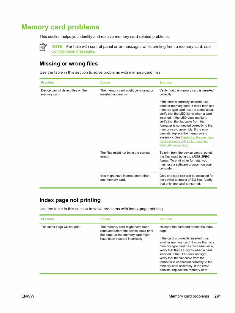
Memory card problemsThis section helps you identify and resolve memory card-related problems.
NOTE For help with control-panel error messages while printing from a memory card, seeControl-panel messages.
Missing or wrong filesUse the table in this section to solve problems with memory-card files.
Problem Cause Solution
Device cannot detect files on thememory card.
The memory card might be missing orinserted incorrectly.
Verify that the memory card is insertedcorrectly.
If the card is correctly inserted, useanother memory card. If more than onememory type card has the same issue,verify that the LED lights when a cardinserted. If the LED does not light,verify that the flat cable from theformatter is connected correctly to thememory-card assembly. If the errorpersists, replace the memory-cardassembly. See Replacing the memory-card assembly (HP Color LaserJet2840 all-in-one only).
The files might not be in the correctformat.
To print from the device control panel,the files must be in the sRGB JPEGformat. To print other formats, youmust use a software program on yourcomputer.
You might have inserted more thanone memory card.
Only one card slot can be occupied forthe device to detect JPEG files. Verifythat only one card is inserted.
Index page not printingUse the table in this section to solve problems with index-page printing.
Problem Cause Solution
The index page will not print. The memory card might have beenremoved before the device could printthe page, or the memory card mighthave been inserted incorrectly.
Reinsert the card and reprint the indexpage.
If the card is correctly inserted, useanother memory card. If more than onememory type card has the same issue,verify that the LED lights when a cardinserted. If the LED does not light,verify that the flat cable from theformatter is connected correctly to thememory-card assembly. If the errorpersists, replace the memory-card
ENWW Memory card problems 291
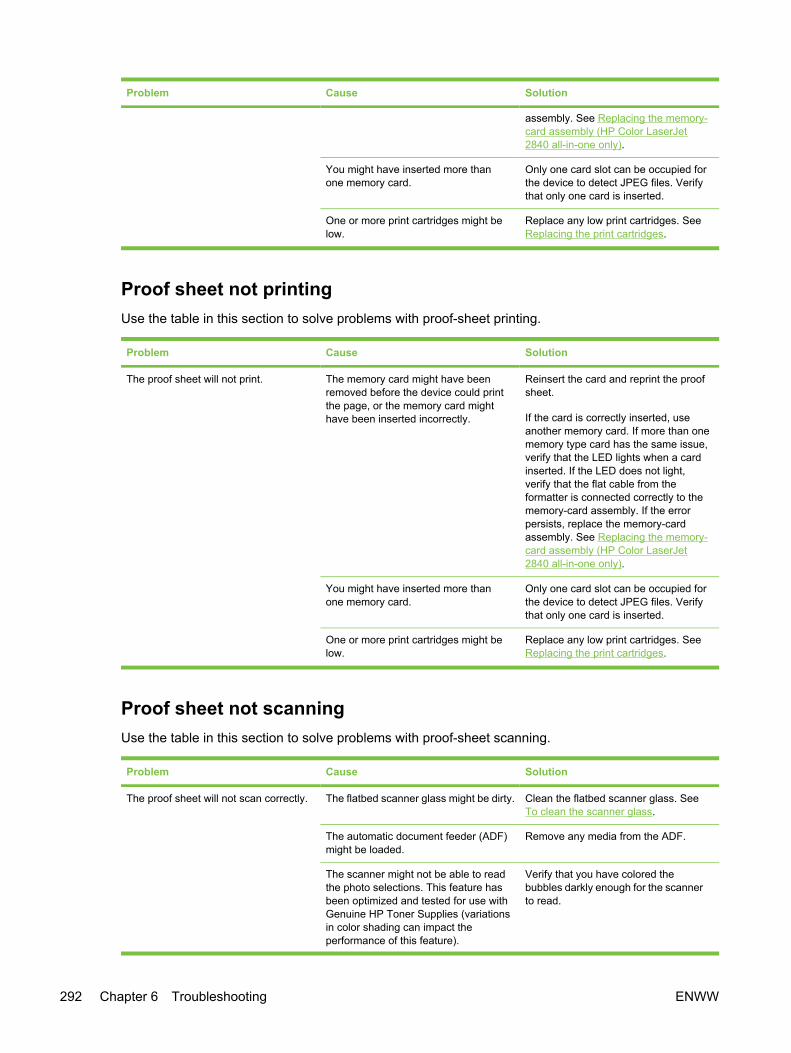
Problem Cause Solution
assembly. See Replacing the memory-card assembly (HP Color LaserJet2840 all-in-one only).
You might have inserted more thanone memory card.
Only one card slot can be occupied forthe device to detect JPEG files. Verifythat only one card is inserted.
One or more print cartridges might below.
Replace any low print cartridges. SeeReplacing the print cartridges.
Proof sheet not printingUse the table in this section to solve problems with proof-sheet printing.
Problem Cause Solution
The proof sheet will not print. The memory card might have beenremoved before the device could printthe page, or the memory card mighthave been inserted incorrectly.
Reinsert the card and reprint the proofsheet.
If the card is correctly inserted, useanother memory card. If more than onememory type card has the same issue,verify that the LED lights when a cardinserted. If the LED does not light,verify that the flat cable from theformatter is connected correctly to thememory-card assembly. If the errorpersists, replace the memory-cardassembly. See Replacing the memory-card assembly (HP Color LaserJet2840 all-in-one only).
You might have inserted more thanone memory card.
Only one card slot can be occupied forthe device to detect JPEG files. Verifythat only one card is inserted.
One or more print cartridges might below.
Replace any low print cartridges. SeeReplacing the print cartridges.
Proof sheet not scanningUse the table in this section to solve problems with proof-sheet scanning.
Problem Cause Solution
The proof sheet will not scan correctly. The flatbed scanner glass might be dirty. Clean the flatbed scanner glass. SeeTo clean the scanner glass.
The automatic document feeder (ADF)might be loaded.
Remove any media from the ADF.
The scanner might not be able to readthe photo selections. This feature hasbeen optimized and tested for use withGenuine HP Toner Supplies (variationsin color shading can impact theperformance of this feature).
Verify that you have colored thebubbles darkly enough for the scannerto read.
292 Chapter 6 Troubleshooting ENWW
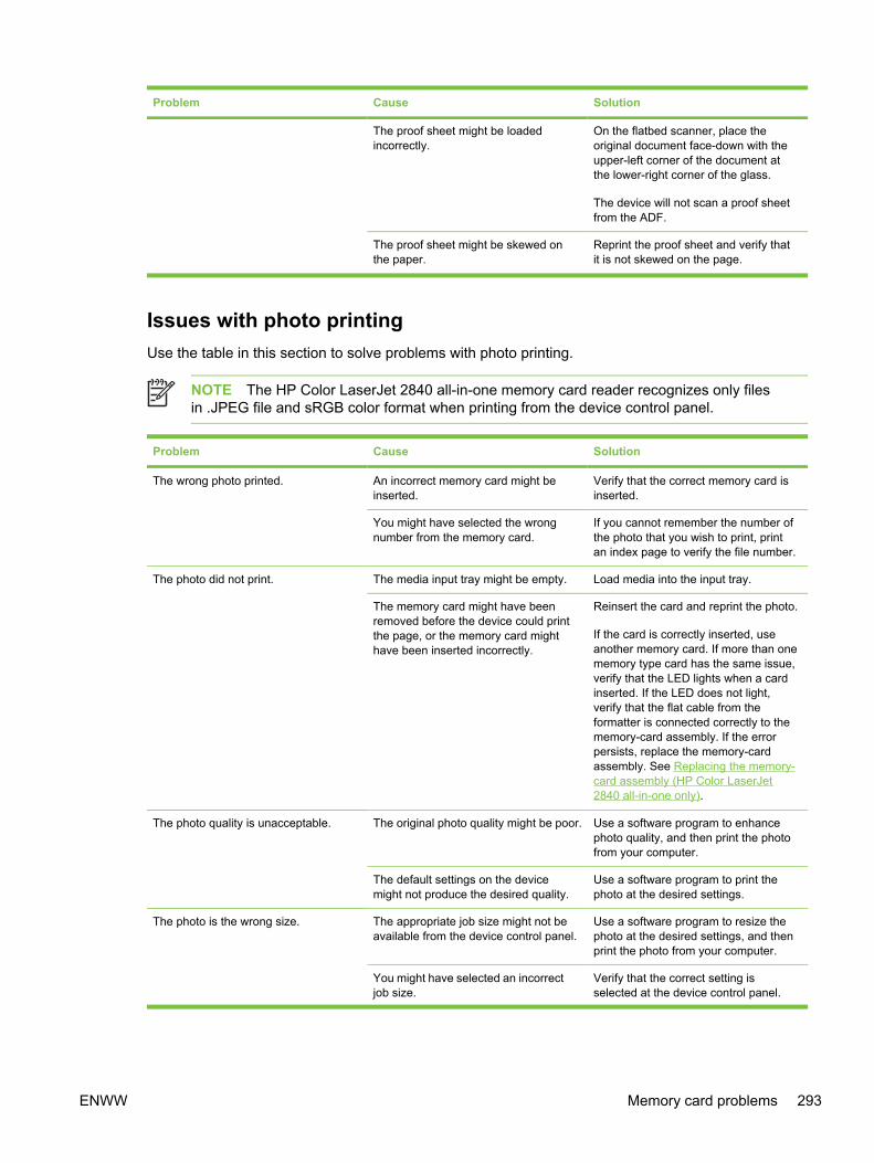
Problem Cause Solution
The proof sheet might be loadedincorrectly.
On the flatbed scanner, place theoriginal document face-down with theupper-left corner of the document atthe lower-right corner of the glass.
The device will not scan a proof sheetfrom the ADF.
The proof sheet might be skewed onthe paper.
Reprint the proof sheet and verify thatit is not skewed on the page.
Issues with photo printingUse the table in this section to solve problems with photo printing.
NOTE The HP Color LaserJet 2840 all-in-one memory card reader recognizes only filesin .JPEG file and sRGB color format when printing from the device control panel.
Problem Cause Solution
The wrong photo printed. An incorrect memory card might beinserted.
Verify that the correct memory card isinserted.
You might have selected the wrongnumber from the memory card.
If you cannot remember the number ofthe photo that you wish to print, printan index page to verify the file number.
The photo did not print. The media input tray might be empty. Load media into the input tray.
The memory card might have beenremoved before the device could printthe page, or the memory card mighthave been inserted incorrectly.
Reinsert the card and reprint the photo.
If the card is correctly inserted, useanother memory card. If more than onememory type card has the same issue,verify that the LED lights when a cardinserted. If the LED does not light,verify that the flat cable from theformatter is connected correctly to thememory-card assembly. If the errorpersists, replace the memory-cardassembly. See Replacing the memory-card assembly (HP Color LaserJet2840 all-in-one only).
The photo quality is unacceptable. The original photo quality might be poor. Use a software program to enhancephoto quality, and then print the photofrom your computer.
The default settings on the devicemight not produce the desired quality.
Use a software program to print thephoto at the desired settings.
The photo is the wrong size. The appropriate job size might not beavailable from the device control panel.
Use a software program to resize thephoto at the desired settings, and thenprint the photo from your computer.
You might have selected an incorrectjob size.
Verify that the correct setting isselected at the device control panel.
ENWW Memory card problems 293

Problem Cause Solution
Cannot edit, save, or delete images onthe memory card.
The device cannot read the memorycard.
Verify that the memory card is properlyinserted and that the card is one that issupported.
NOTE You cannot editmemory-card files from thedevice control panel. Use asoftware program to edit,delete, or save images.
Scanner did not read proof sheet. The device is using non-HP supplies.This feature has been optimized andtested for use with Genuine HP TonerSupplies (variations in color shadingcan impact the performance of thisfeature).
Use a software program to print thephoto from your computer.
Print photos directly from the memorycard by using the control panel.
Install HP supplies in the device andreprint the proof sheet.
The proof sheet might be skewed onthe paper.
Reprint the proof sheet and verify thatit is not skewed on the page.
294 Chapter 6 Troubleshooting ENWW

Functional tests
Engine testThe purpose of the engine test is to determine which image-formation process is malfunctioning. Theimage-formation process can be divided into the following stages:
■ Conditioning stage (charges the drum)
■ Writing stage (writes a latent image to the drum with the laser)
■ Development stage (forms a toner image on the drum)
■ Transfer stage (transfers the image to paper)
■ Separation stage (separates the media from the drum)
■ Fusing stage (applies heat and pressure to make the image on paper permanent)
■ Cleaning stage (removes excess toner from the drum)
The engine test switch is inside tray 1, on the left side, just below the front cover.
To print an engine test:
1 Turn off the device.
2 Turn on the device.
3 Open tray 1 and load paper.
NOTE If tray 1 is empty, the device will not perform an engine test. You cannot performan engine test from optional tray 2.
4 Press the engine-test switch (shown below).
NOTE The formatter must be connected to the power supply cover plate to perform anengine test. Otherwise, the device does not print the engine test.
Figure 6-1 Location of the engine-test switch
The device prints an engine-test page that contains four columns of horizontal lines, with eachcolumn corresponding to one of the print cartridge colors.
ENWW Functional tests 295
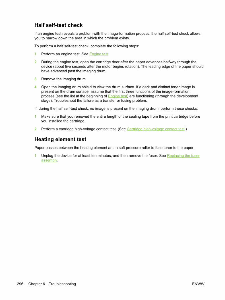
Half self-test checkIf an engine test reveals a problem with the image-formation process, the half self-test check allowsyou to narrow down the area in which the problem exists.
To perform a half self-test check, complete the following steps:
1 Perform an engine test. See Engine test.
2 During the engine test, open the cartridge door after the paper advances halfway through thedevice (about five seconds after the motor begins rotation). The leading edge of the paper shouldhave advanced past the imaging drum.
3 Remove the imaging drum.
4 Open the imaging drum shield to view the drum surface. If a dark and distinct toner image ispresent on the drum surface, assume that the first three functions of the image-formationprocess (see the list at the beginning of Engine test) are functioning (through the developmentstage). Troubleshoot the failure as a transfer or fusing problem.
If, during the half self-test check, no image is present on the imaging drum, perform these checks:
1 Make sure that you removed the entire length of the sealing tape from the print cartridge beforeyou installed the cartridge.
2 Perform a cartridge high-voltage contact test. (See Cartridge high-voltage contact test.)
Heating element testPaper passes between the heating element and a soft pressure roller to fuse toner to the paper.
1 Unplug the device for at least ten minutes, and then remove the fuser. See Replacing the fuserassembly.
296 Chapter 6 Troubleshooting ENWW
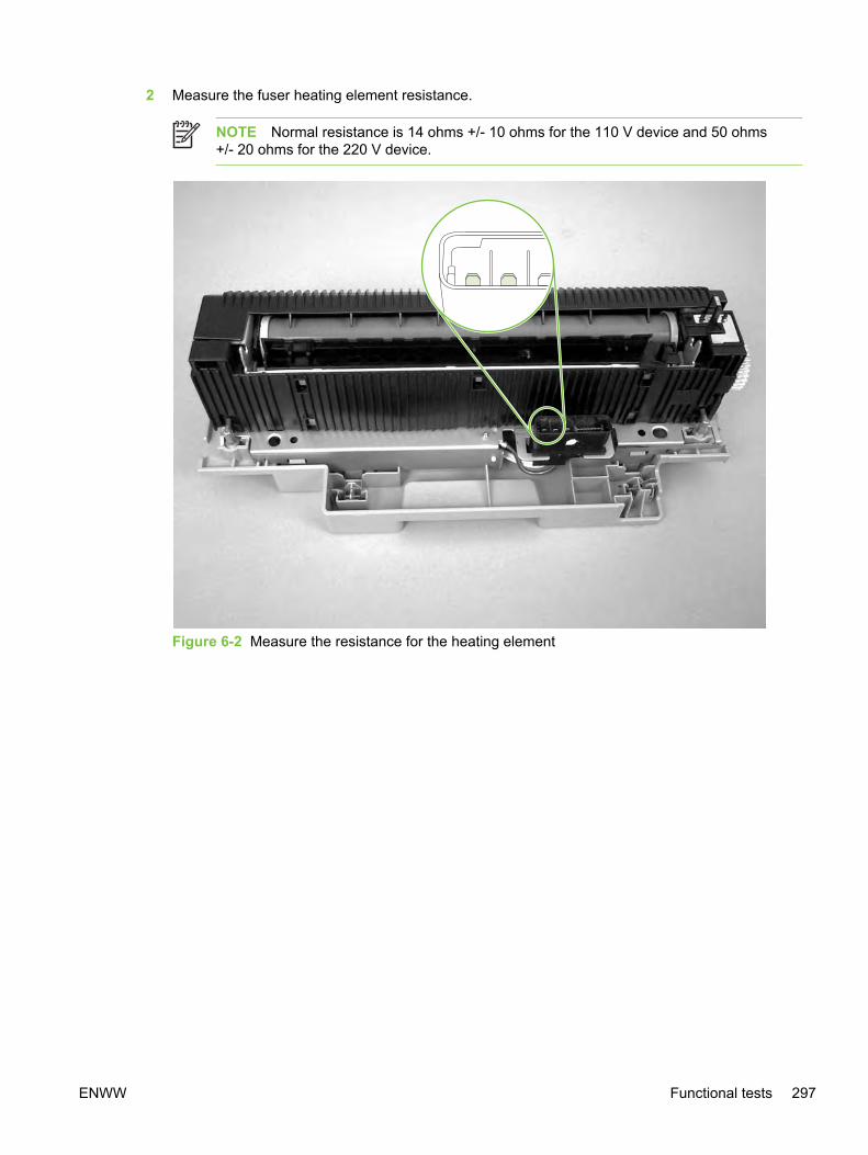
2 Measure the fuser heating element resistance.
NOTE Normal resistance is 14 ohms +/- 10 ohms for the 110 V device and 50 ohms+/- 20 ohms for the 220 V device.
Figure 6-2 Measure the resistance for the heating element
ENWW Functional tests 297
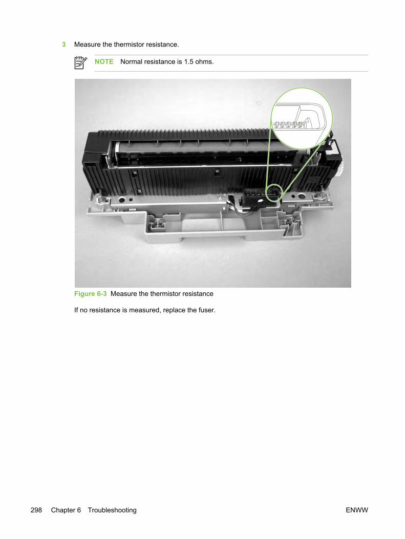
3 Measure the thermistor resistance.
NOTE Normal resistance is 1.5 ohms.
Figure 6-3 Measure the thermistor resistance
If no resistance is measured, replace the fuser.
298 Chapter 6 Troubleshooting ENWW

Cartridge high-voltage contact testTo check the print cartridge connection points, complete the following steps:
1 Turn the print cartridge over and visually inspect the two connection points on the ends of theprint cartridge. If they are dirty or corroded, clean the connections. If they are damaged, replacethe print cartridge.
Figure 6-4 Print cartridge high-voltage contacts
2 If the connection points are dirty or corroded, then clean the connections. If they are damaged,then replace the print cartridge.
NOTE Use only isopropyl alcohol to clean the connections.
Paper-path testIf media is not being picked up or is not moving through the paper path, you might want to observeall of the paper-motion activities. Override the door interlock (SW301) and the laser/scanner switch toobserve the following actions:
■ Motor rotation
■ Solenoid action
■ Pickup-roller motion
■ Drive-roller, transfer-roller, fuser-roller and gear, and delivery-roller motion
1 To override the door interlock (SW301), push a piece of heavy paper into the slot in the top cover(callout 1) to override SW301.
ENWW Functional tests 299
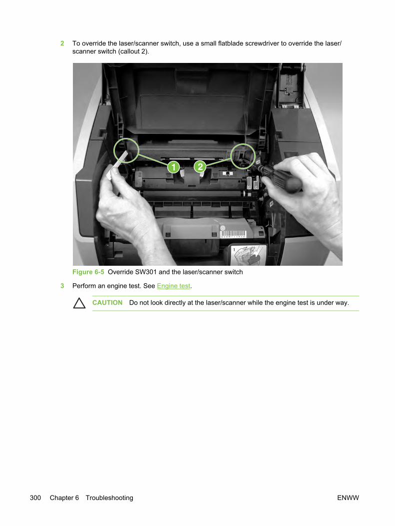
2 To override the laser/scanner switch, use a small flatblade screwdriver to override the laser/scanner switch (callout 2).
Figure 6-5 Override SW301 and the laser/scanner switch
3 Perform an engine test. See Engine test.
CAUTION Do not look directly at the laser/scanner while the engine test is under way.
300 Chapter 6 Troubleshooting ENWW
Service-mode functionsUse the following information to perform system-wide reset procedures and to adjust certain globalsettings such as the country/region. Users do not have access to this information.
NVRAM initializationAn NVRAM initialization will return the device settings to the factory-set defaults, including:
■ All menu settings, including the fax header and company name
■ Fax numbers and names that are associated with one-touch keys and speed-dial codes
Additionally, all faxes stored in memory are cleared.
1 Turn off the device.
2 Simultaneously press and hold the ENTER button and the * button, and then turn on the device.
3 Wait until the message Permanent storage init. appears, and then release the ENTER and *buttons.
When the NVRAM initialization process has been completed, the device control panel shows theReady message.
Secondary service menuUse the secondary service menu to perform various tests and print service reports. The following is ahierarchical diagram of the secondary service menu.
Table 6-5 Secondary service menu
Main menu Submenu Submenu
2ndary Service Service Reports Cont. Self-Test
Extended Keymap
Error Report
Location USA
1=Yes 2=No
Display test (none)
Show FW Version (none)
ENWW Service-mode functions 301

Main menu Submenu Submenu
Memory Cards
(HP Color LaserJet 2840 all-in-one only)
Enabled
Disabled
Color Cal. Adjust color
■ Contrasts
■ Cyan density
■ Magenta density
■ Yellow density
■ Black density
■ Highlights
■ Cyan density
■ Magenta density
■ Yellow density
■ Black density
■ Midtones
■ Cyan density
■ Magenta density
■ Yellow density
■ Black density
■ Shadows
■ Cyan density
■ Magenta density
■ Yellow density
■ Black density
Timing
■ Off
■ 12 hours
■ 24 hours
■ 48 hours
■ 96 hours
■ 128 hours
■ 168 hours
Table 6-5 Secondary service menu (continued)
302 Chapter 6 Troubleshooting ENWW

To print secondary service reports1 Make sure that the control-panel display reads Ready.
2 Press MENU.
3 Press 2 on the keypad.
NOTE You can gain access to the secondary service menu from any other menu bypressing 2.
4 Use the < or > button to select Service Reports, and then press Enter.
5 Use the < or > button to select one of the following reports:
● Cont. Self-Test
● Extended Keymap
● Error Report (see Error log)
6 Press Enter to print the report.
7 To exit the secondary service menu and remove it from the menu tree, press CANCEL to return tothe Ready display, and then press CANCEL again.
To reset the device location
The device location setting affects telecom (fax) and other settings, depending on the country/regionin which the device is used. To change the device location setting, complete the following steps.
1 Make sure that the control-panel display reads Ready.
2 Press MENU.
3 Press 2 on the keypad.
NOTE You can gain access to the secondary service menu from any other menu bypressing 2.
4 Use the < or > button to select Location, and then press Enter.
5 Use the < or > button to select the country/region in which the device is operating, and thenpress Enter.
6 Press 1 to select Yes.
The device turns off and then turns on. When the device returns to the Ready state, it reflectsthe new location setting.
ENWW Service-mode functions 303
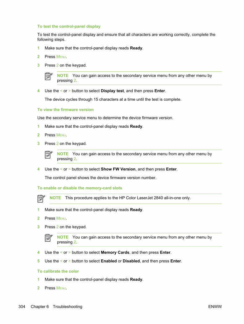
To test the control-panel display
To test the control-panel display and ensure that all characters are working correctly, complete thefollowing steps.
1 Make sure that the control-panel display reads Ready.
2 Press MENU.
3 Press 2 on the keypad.
NOTE You can gain access to the secondary service menu from any other menu bypressing 2.
4 Use the < or > button to select Display test, and then press Enter.
The device cycles through 15 characters at a time until the test is complete.
To view the firmware version
Use the secondary service menu to determine the device firmware version.
1 Make sure that the control-panel display reads Ready.
2 Press MENU.
3 Press 2 on the keypad.
NOTE You can gain access to the secondary service menu from any other menu bypressing 2.
4 Use the < or > button to select Show FW Version, and then press Enter.
The control panel shows the device firmware version number.
To enable or disable the memory-card slots
NOTE This procedure applies to the HP Color LaserJet 2840 all-in-one only.
1 Make sure that the control-panel display reads Ready.
2 Press MENU.
3 Press 2 on the keypad.
NOTE You can gain access to the secondary service menu from any other menu bypressing 2.
4 Use the < or > button to select Memory Cards, and then press Enter.
5 Use the < or > button to select Enabled or Disabled, and then press Enter.
To calibrate the color
1 Make sure that the control-panel display reads Ready.
2 Press MENU.
304 Chapter 6 Troubleshooting ENWW

3 Press 2 on the keypad.
NOTE You can gain access to the secondary service menu from any other menu bypressing 2.
4 Use the < or > button to select Color Cal., and then press Enter.
5 Use the < or > button to select one of the following settings:
● Contrasts
● Highlights
● Midtones
● Shadows
Press Enter.
6 Use the < or > button to select one of the following color settings:
● Cyan density
● Magenta density
● Yellow density
● Black density
Press Enter.
7 Use the < or > button to adjust the density setting. Increasing the setting darkens the density,while decreasing the setting lightens the density.
8 Press Enter to save the setting.
ENWW Service-mode functions 305
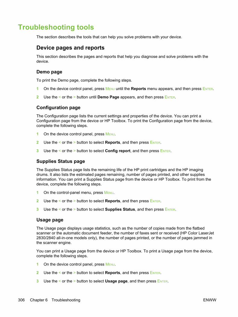
Troubleshooting toolsThe section describes the tools that can help you solve problems with your device.
Device pages and reportsThis section describes the pages and reports that help you diagnose and solve problems with thedevice.
Demo pageTo print the Demo page, complete the following steps.
1 On the device control panel, press MENU until the Reports menu appears, and then press ENTER.
2 Use the < or the > button until Demo Page appears, and then press ENTER.
Configuration pageThe Configuration page lists the current settings and properties of the device. You can print aConfiguration page from the device or HP Toolbox. To print the Configuration page from the device,complete the following steps.
1 On the device control panel, press MENU.
2 Use the < or the > button to select Reports, and then press ENTER.
3 Use the < or the > button to select Config report, and then press ENTER.
Supplies Status pageThe Supplies Status page lists the remaining life of the HP print cartridges and the HP imagingdrums. It also lists the estimated pages remaining, number of pages printed, and other suppliesinformation. You can print a Supplies Status page from the device or HP Toolbox. To print from thedevice, complete the following steps.
1 On the control-panel menu, press MENU.
2 Use the < or the > button to select Reports, and then press ENTER.
3 Use the < or the > button to select Supplies Status, and then press ENTER.
Usage pageThe Usage page displays usage statistics, such as the number of copies made from the flatbedscanner or the automatic document feeder, the number of faxes sent or received (HP Color LaserJet2830/2840 all-in-one models only), the number of pages printed, or the number of pages jammed inthe scanner engine.
You can print a Usage page from the device or HP Toolbox. To print a Usage page from the device,complete the following steps.
1 On the device control panel, press MENU.
2 Use the < or the > button to select Reports, and then press ENTER.
3 Use the < or the > button to select Usage page, and then press ENTER.
306 Chapter 6 Troubleshooting ENWW
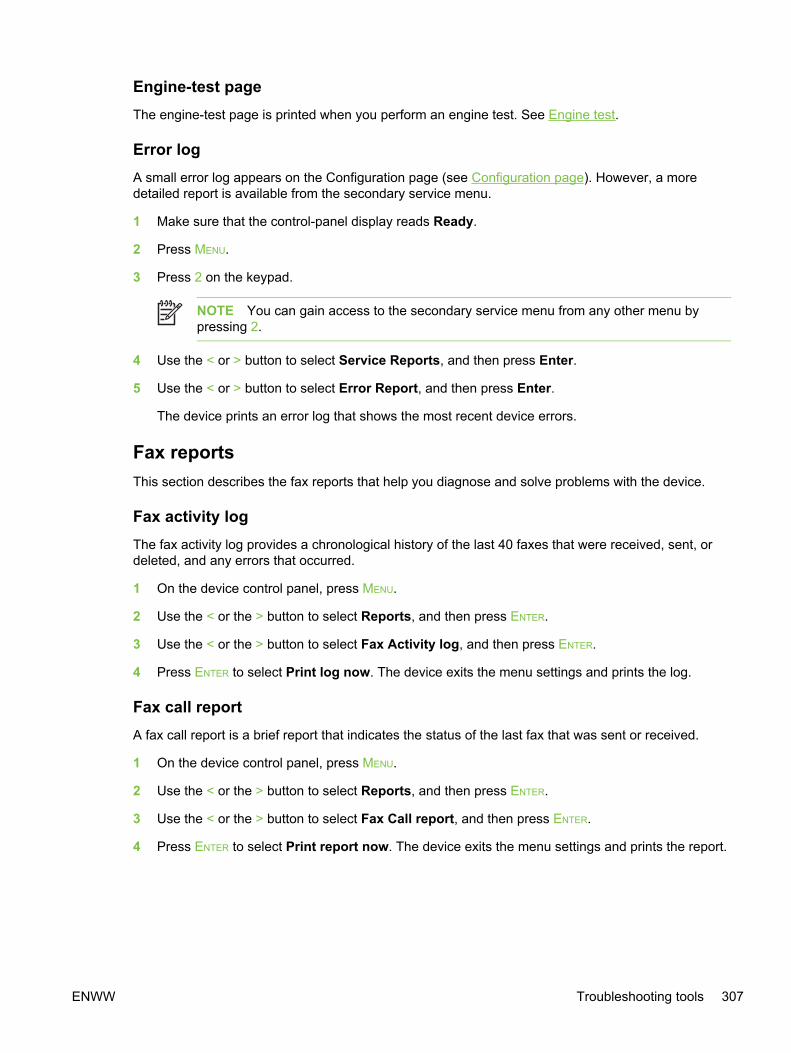
Engine-test pageThe engine-test page is printed when you perform an engine test. See Engine test.
Error logA small error log appears on the Configuration page (see Configuration page). However, a moredetailed report is available from the secondary service menu.
1 Make sure that the control-panel display reads Ready.
2 Press MENU.
3 Press 2 on the keypad.
NOTE You can gain access to the secondary service menu from any other menu bypressing 2.
4 Use the < or > button to select Service Reports, and then press Enter.
5 Use the < or > button to select Error Report, and then press Enter.
The device prints an error log that shows the most recent device errors.
Fax reportsThis section describes the fax reports that help you diagnose and solve problems with the device.
Fax activity logThe fax activity log provides a chronological history of the last 40 faxes that were received, sent, ordeleted, and any errors that occurred.
1 On the device control panel, press MENU.
2 Use the < or the > button to select Reports, and then press ENTER.
3 Use the < or the > button to select Fax Activity log, and then press ENTER.
4 Press ENTER to select Print log now. The device exits the menu settings and prints the log.
Fax call reportA fax call report is a brief report that indicates the status of the last fax that was sent or received.
1 On the device control panel, press MENU.
2 Use the < or the > button to select Reports, and then press ENTER.
3 Use the < or the > button to select Fax Call report, and then press ENTER.
4 Press ENTER to select Print report now. The device exits the menu settings and prints the report.
ENWW Troubleshooting tools 307

T.30 protocol traceUse a T.30 protocol trace report to troubleshoot fax transmission issues.
Send a fax from the device or receive a fax to the device from another fax machine, and then print aT.30 trace report after the fax prints.
1 On the device control panel, press MENU.
2 Use the < or the > button to select Service, and then press ENTER.
3 Use the < or the > button to select Print T.30, and then press ENTER.
The device exits the menu settings and prints the reports.
Explanations of some of the report’s column headings follow:
● Date and Time identify when the fax begins.
● Type is the type of fax activity: send or receive.
● Identification is the phone number to which a fax is sent.
● Result explains the status of the fax:
■ “OK” means that the fax was successful.
■ “Pending” faxes are in memory or are printing.
■ An error code means that your device might need service. The following tables, Table6-6 Fax receive error codes and Table 6-7 Fax send error codes, define the error codes.
NOTE These codes also appear in the fax call report and the fax activity log.
Table 6-6 Fax receive error codes
Error code Description Solution
200 The fax session has completed without errors. N/A
221 User has pressed CANCEL button, causing the faxsession to be prematurely halted.
Have sender resend the fax.
222 The receiving device has answered a call but hasbeen unable to detect the presence of a callingfax device for one of the following reasons:
● Typically this will be due to the receiving faxdevice answering a voice call.
● The sender canceled the fax transmission bypressing the CANCEL button immediately priorto, or just as the receiving device answeredthe call.
● The sending device automatically ended thecall immediately prior to, or just as thereceiving device answered the call.
1 Confirm that the sender is a fax device andnot a voice caller - typically you must rely onthe sender informing the caller that the faxsession is failing.
2 If the sending device ends the call just as thereceiving device starts reception, reduce thering count after which the receiving deviceanswers. Alternatively suggest that thesender manually dials to the receiving deviceand then manually starts the fax session, bypressing theSTART FAX button once fax toneshave been heard from the receiving device.
3 Confirm that the sender is not inadvertentlyattempting to poll transmit from the receiving
308 Chapter 6 Troubleshooting ENWW
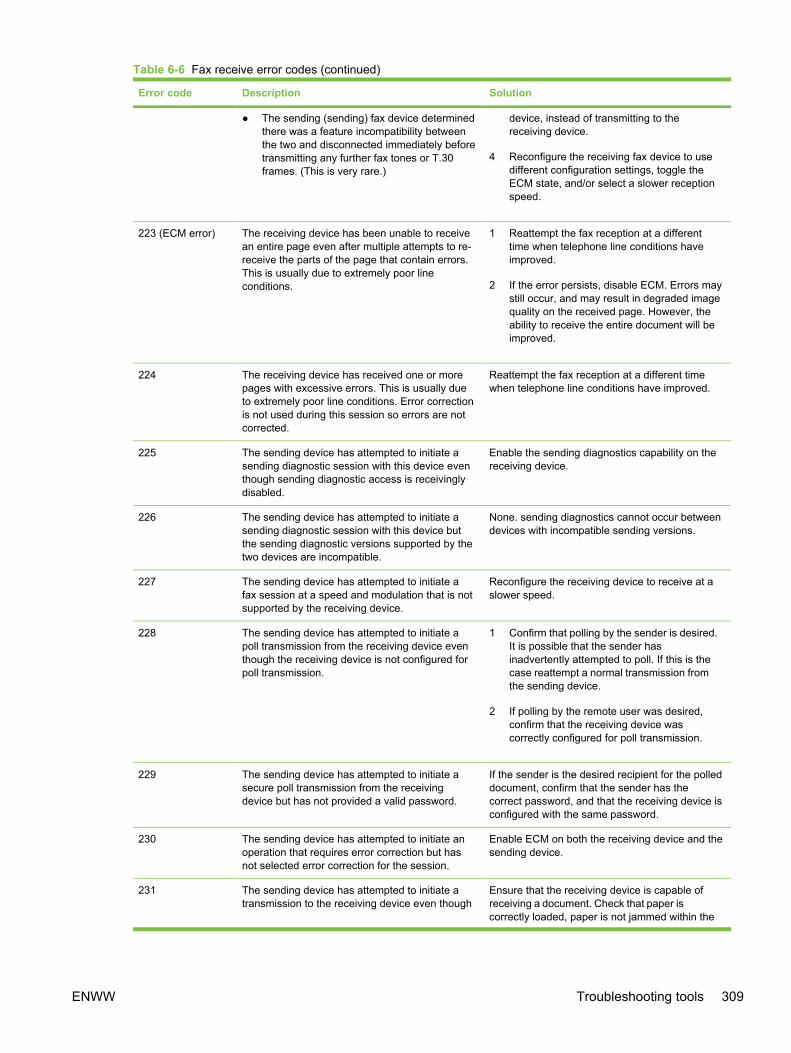
Error code Description Solution
● The sending (sending) fax device determinedthere was a feature incompatibility betweenthe two and disconnected immediately beforetransmitting any further fax tones or T.30frames. (This is very rare.)
device, instead of transmitting to thereceiving device.
4 Reconfigure the receiving fax device to usedifferent configuration settings, toggle theECM state, and/or select a slower receptionspeed.
223 (ECM error) The receiving device has been unable to receivean entire page even after multiple attempts to re-receive the parts of the page that contain errors.This is usually due to extremely poor lineconditions.
1 Reattempt the fax reception at a differenttime when telephone line conditions haveimproved.
2 If the error persists, disable ECM. Errors maystill occur, and may result in degraded imagequality on the received page. However, theability to receive the entire document will beimproved.
224 The receiving device has received one or morepages with excessive errors. This is usually dueto extremely poor line conditions. Error correctionis not used during this session so errors are notcorrected.
Reattempt the fax reception at a different timewhen telephone line conditions have improved.
225 The sending device has attempted to initiate asending diagnostic session with this device eventhough sending diagnostic access is receivinglydisabled.
Enable the sending diagnostics capability on thereceiving device.
226 The sending device has attempted to initiate asending diagnostic session with this device butthe sending diagnostic versions supported by thetwo devices are incompatible.
None. sending diagnostics cannot occur betweendevices with incompatible sending versions.
227 The sending device has attempted to initiate afax session at a speed and modulation that is notsupported by the receiving device.
Reconfigure the receiving device to receive at aslower speed.
228 The sending device has attempted to initiate apoll transmission from the receiving device eventhough the receiving device is not configured forpoll transmission.
1 Confirm that polling by the sender is desired.It is possible that the sender hasinadvertently attempted to poll. If this is thecase reattempt a normal transmission fromthe sending device.
2 If polling by the remote user was desired,confirm that the receiving device wascorrectly configured for poll transmission.
229 The sending device has attempted to initiate asecure poll transmission from the receivingdevice but has not provided a valid password.
If the sender is the desired recipient for the polleddocument, confirm that the sender has thecorrect password, and that the receiving device isconfigured with the same password.
230 The sending device has attempted to initiate anoperation that requires error correction but hasnot selected error correction for the session.
Enable ECM on both the receiving device and thesending device.
231 The sending device has attempted to initiate atransmission to the receiving device even though
Ensure that the receiving device is capable ofreceiving a document. Check that paper iscorrectly loaded, paper is not jammed within the
Table 6-6 Fax receive error codes (continued)
ENWW Troubleshooting tools 309

Error code Description Solution
the capability to receive is disabled at thereceiving device.
device, and any other system abnormalities havebeen cleared.
232 One of the following has occurred:
● A communication failure has occurredbetween the two devices.
● The user at the remote device may havepressed the CANCEL button.
● The power at the remote device has beeninterrupted or deliberately turned off, causingthe fax session to be interrupted.
1 Re-attempt the fax reception at a differenttime when telephone line conditions haveimproved.
2 If the error persists, and error correction is inuse for the fax session, disable ECM.
233 and 234
235 and 236 (ECMerror)
237
238 The sending fax device sent an unexpectedcommunication. This is a defect in the sendingdevice.
N/A
239–241
242 The sending fax device is attempting to receiveinstead of send. Both devices have attempted tostart a reception at the same time. It is possibleto accidentally initiate a fax reception after dialingon many devices, if there is no paper in thedevice or if the paper is not correctly loaded andcannot be sensed by the appropriate documentsensor.
Ensure that a document is ready and correctlyloaded in the sending fax device and that thesending device is attempting to initiate atransmission and not a reception.
243 and 244 One of the following has occurred:
● The user of the remote device has pressedthat device's CANCEL button, causing thesession to be prematurely terminated.
● The sending fax device determined therewas a feature incompatibility between thetwo devices and has terminated the session.An example would be when the receivingdevice wanted to initiate polling, but thesending device did not support this mode ofoperation.
1 Confirm that the sender is not inadvertentlyattempting to poll transmit from the receivingdevice, instead of transmitting to thereceiving device. This mode of operationmust be specially configured on the receivingdevice. If poll transmission from the receivingdevice is the desired mode of operation,confirm that the receiving device has beenconfigured for this operation.
2 2. Reconfigure the receiving fax device touse different configuration settings, togglethe ECM state, and/or select a slowerreception speed.
245 and 246 (ECMerror)
The user of the sending device has pressed thatdevice's CANCEL button, causing the session to beprematurely terminated. The receiving device hasbeen "holding off" the remote device duringreception of a large and/or complex documentdue to lack of available memory. This hold-offtime has exceeded the timeout (typically 60seconds) used by the sending device, and it hasterminated the session.
1 If the document was large, ask the sender toretransmit the document as two or moresmaller documents.
2 Disable ECM and reattempt the fax reception.
247-251 The sending device appears to be "stuck on." N/A
Table 6-6 Fax receive error codes (continued)
310 Chapter 6 Troubleshooting ENWW
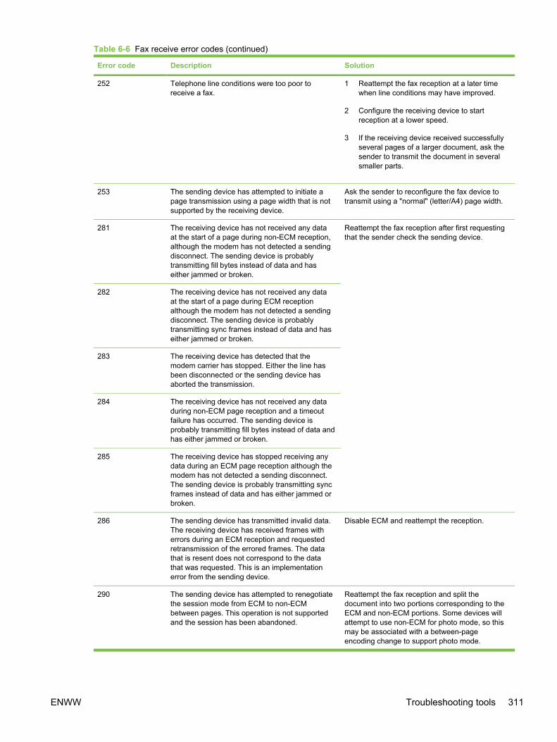
Error code Description Solution
252 Telephone line conditions were too poor toreceive a fax.
1 Reattempt the fax reception at a later timewhen line conditions may have improved.
2 Configure the receiving device to startreception at a lower speed.
3 If the receiving device received successfullyseveral pages of a larger document, ask thesender to transmit the document in severalsmaller parts.
253 The sending device has attempted to initiate apage transmission using a page width that is notsupported by the receiving device.
Ask the sender to reconfigure the fax device totransmit using a "normal" (letter/A4) page width.
281 The receiving device has not received any dataat the start of a page during non-ECM reception,although the modem has not detected a sendingdisconnect. The sending device is probablytransmitting fill bytes instead of data and haseither jammed or broken.
Reattempt the fax reception after first requestingthat the sender check the sending device.
282 The receiving device has not received any dataat the start of a page during ECM receptionalthough the modem has not detected a sendingdisconnect. The sending device is probablytransmitting sync frames instead of data and haseither jammed or broken.
283 The receiving device has detected that themodem carrier has stopped. Either the line hasbeen disconnected or the sending device hasaborted the transmission.
284 The receiving device has not received any dataduring non-ECM page reception and a timeoutfailure has occurred. The sending device isprobably transmitting fill bytes instead of data andhas either jammed or broken.
285 The receiving device has stopped receiving anydata during an ECM page reception although themodem has not detected a sending disconnect.The sending device is probably transmitting syncframes instead of data and has either jammed orbroken.
286 The sending device has transmitted invalid data.The receiving device has received frames witherrors during an ECM reception and requestedretransmission of the errored frames. The datathat is resent does not correspond to the datathat was requested. This is an implementationerror from the sending device.
Disable ECM and reattempt the reception.
290 The sending device has attempted to renegotiatethe session mode from ECM to non-ECMbetween pages. This operation is not supportedand the session has been abandoned.
Reattempt the fax reception and split thedocument into two portions corresponding to theECM and non-ECM portions. Some devices willattempt to use non-ECM for photo mode, so thismay be associated with a between-pageencoding change to support photo mode.
Table 6-6 Fax receive error codes (continued)
ENWW Troubleshooting tools 311
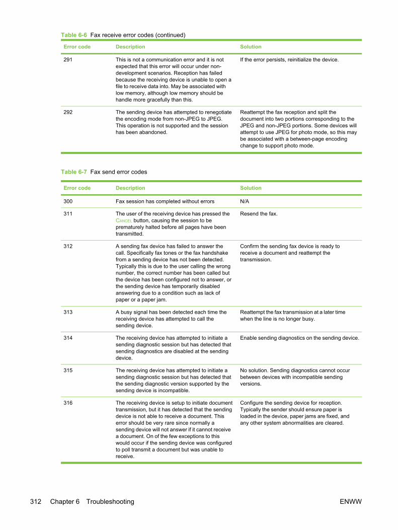
Error code Description Solution
291 This is not a communication error and it is notexpected that this error will occur under non-development scenarios. Reception has failedbecause the receiving device is unable to open afile to receive data into. May be associated withlow memory, although low memory should behandle more gracefully than this.
If the error persists, reinitialize the device.
292 The sending device has attempted to renegotiatethe encoding mode from non-JPEG to JPEG.This operation is not supported and the sessionhas been abandoned.
Reattempt the fax reception and split thedocument into two portions corresponding to theJPEG and non-JPEG portions. Some devices willattempt to use JPEG for photo mode, so this maybe associated with a between-page encodingchange to support photo mode.
Table 6-7 Fax send error codes
Error code Description Solution
300 Fax session has completed without errors N/A
311 The user of the receiving device has pressed theCANCEL button, causing the session to beprematurely halted before all pages have beentransmitted.
Resend the fax.
312 A sending fax device has failed to answer thecall. Specifically fax tones or the fax handshakefrom a sending device has not been detected.Typically this is due to the user calling the wrongnumber, the correct number has been called butthe device has been configured not to answer, orthe sending device has temporarily disabledanswering due to a condition such as lack ofpaper or a paper jam.
Confirm the sending fax device is ready toreceive a document and reattempt thetransmission.
313 A busy signal has been detected each time thereceiving device has attempted to call thesending device.
Reattempt the fax transmission at a later timewhen the line is no longer busy.
314 The receiving device has attempted to initiate asending diagnostic session but has detected thatsending diagnostics are disabled at the sendingdevice.
Enable sending diagnostics on the sending device.
315 The receiving device has attempted to initiate asending diagnostic session but has detected thatthe sending diagnostic version supported by thesending device is incompatible.
No solution. Sending diagnostics cannot occurbetween devices with incompatible sendingversions.
316 The receiving device is setup to initiate documenttransmission, but it has detected that the sendingdevice is not able to receive a document. Thiserror should be very rare since normally asending device will not answer if it cannot receivea document. On of the few exceptions to thiswould occur if the sending device was configuredto poll transmit a document but was unable toreceive.
Configure the sending device for reception.Typically the sender should ensure paper isloaded in the device, paper jams are fixed, andany other system abnormalities are cleared.
Table 6-6 Fax receive error codes (continued)
312 Chapter 6 Troubleshooting ENWW

Error code Description Solution
317 The sending device cannot support a faxreception at any speed or modulation that issupported by the receiving device.
N/A
318 The sending device cannot support a faxreception at the page width selected by thereceiving device.
N/A
319 The receiving device has attempted to initiate abinary file transfer (BFT) but has detected thatthe sending device does not support this mode ofoperation.
Do one of the following:
● Enable the BFT capability on the sendingdevice if it is supported.
● Retransmit the document as a normal fax,rather than attempting a BFT transfer.
320 The receiving device is set up to initiate pollreception with a sending device, but it hasdetected that the sending device is notconfigured to do this. Poll transmission from asending device is typically configured on asession-by-session basis.
Do one of the following:
● Confirm that the receiver really wants toattempt a poll reception. If not, reconfigurethe receiving device for a normal faxtransmission
● Configure the sending device for polltransmission. The sender must load adocument to transmit and then configure thedevice for polling.
321 There was a communication error with thereceiving fax device due to poor telephone lineconditions.
Reattempt the fax transmission at a different timewhen telephone line conditions have improved.
322–324 Telephone line conditions were too poor to senda fax.
1 Reattempt the fax transmission at a differenttime when telephone line conditions haveimproved.
2 If the session fails after transmitting severalpages of a large document, retransmit thedocument as several smaller documents.
325-328 (ECMerror)
Telephone line conditions were very poor. 1 Reattempt the fax transmission at a differenttime when telephone line conditions haveimproved.
2 If the error persists, disable ECM. Errors maystill occur, and may result in a degradedimage quality on the received page.However, the ability to transmit the entiredocument will be improved.
329–331 The sending device has reported that one ormore pages have been received (non-ECMmode) with excessive errors. This error does notresult in the session being terminatedimmediately. Subsequent page transmission canstill occur and later pages may be receivedwithout error.
1 Reattempt the fax transmission at a differenttime when telephone line conditions haveimproved.
2 If the error persists, select a lower speed forthe initial transmission speed.
332–337 There is a defect in the sending fax device. Send from another device.
Table 6-7 Fax send error codes (continued)
ENWW Troubleshooting tools 313

Error code Description Solution
338–342 (ECMerror)
343
344–348 One of the following has occurred:
● The sending device has failed to respond toa fax command from the receiving devicedue to the connection being interrupted.
● The sender has pressed the CANCEL buttonwhile the reception was in progress.
● In rare conditions, incompatibility betweenthe two devices may cause the sendingdevice to abandon the call.
1 Reattempt the fax transmission at a differenttime when telephone line conditions haveimproved.
2 fax session was using error correction,disable ECM.
349-353 (ECMerror)
354 and 355
356-361 One of the following has occurred:
● The sender has pressed the CANCEL button,causing the session to be aborted.
● The sending device has encountered asystem problem such as no paper or a paperjam, which has inhibited it from receiving anymore pages, and which has caused it toterminate the session prematurely.
● A feature incompatibility has beenencountered by the sending device, causingit to terminate the session.
1 Configure the sending device for documentreception by clearing any paper jams,loading sufficient paper, and clearing anyother system errors.
2 Configure the receiving fax device to usedifferent configurations, toggle the ECMstate, or select a slower reception speed.
362-366 (ECMerror)
367-372 The sending device appears to be "stuck on". N/A
373-377 (ECMerror)
378 and 379
380 The sending device has failed to issue a validresponse to a CTC frame. This occurs duringECM transmission after multiple retransmissionsof erred data.
Send from another device.
381 One of the following has occurred:
● The sending device has failed to respond toa fax command from the receiving devicedue to the connection being interrupted.
● The sender has pressed the CANCEL buttonwhile the reception was in progress.
1 Reattempt the fax transmission at a differenttime when telephone line conditions haveimproved.
2 If the error persists, disable ECM.
382 The sending fax device has been "holding off" thereceiving fax device from continuing the ongoingtransmission due to a temporary low memorycondition at the sending device. If this "hold-off"period exceeds a device's specific timeout value,the session will terminate.
1 Resend the document as two or moreseparate fax transmissions. Wait severalminutes between the end of onetransmission and the start of the nexttransmission.
2 If the error persists, disable ECM.
Table 6-7 Fax send error codes (continued)
314 Chapter 6 Troubleshooting ENWW

Error code Description Solution
383 One of the following has occurred:
● The sending device has failed to respond toa fax command from the receiving devicedue to the connection being interrupted
● The sender has pressed the CANCEL buttonwhile the reception was in progress.
1 Reattempt the fax transmission at a differenttime when telephone line conditions haveimproved.
2 If the error persists, disable ECM.
384 The receiving device has attempted a blackJPEG transmission to a device that does notsupport this mode.
Reattempt the fax transmission using a differentmode.
385 The receiving device has failed to complete thethird phase of the initial V.34 handshake afteroriginating a fax session. This is usually due topoor line conditions although it may be acompatibility issue with certain devices and/orline conditions.
1 Reattempt the fax transmission at a differenttime when telephone line conditions haveimproved.
2 Disable V.34 on the receiving device andattempt the transmission using the V.17 mode.
387 The receiving device has failed to successfullynegotiate the initial V.8 handshake with thesending device after originating a fax session.Typically this will occur when the sending deviceis not fax capable or has disabled reception. Itmay also be a compatibility issue with certaindevices and/or line conditions.
388 The receiving device has originated a fax sessionand detected a sending fax device but has beenunable to detect any T30 frames. If the device isin V.17 mode it is likely that the connection hasbeen interrupted. In V.34 mode is also possiblefor this error to occur due to compatibilityproblems with certain devices and/or lineconditions.
389 The receiving device has originated a fax sessionand has reattempted V.8 negotiations multipletimes without success.
390 The receiving device has originated a fax sessionusing error correction (either V.34 or V.17).Transmission of an image has been abandonedafter a timeout when no data has become readyfor transmission. This is most likely due to a lowmemory condition although it could be due toother internal problems that cause generation ofdata for transmission to stall.
Reattempt the transmission after making suredocuments stored in memory are printed and thedevice has paper ready for printing. If theproblem persists reinitialize permanent storage.
391 The receiving device has originated a fax sessionwithout error correction (not V.34 ). Transmissionof an image has been abandoned after a timeoutwhen no data has become ready fortransmission. This is most likely due to a lowmemory condition although it could be due toother internal problems that cause generation ofdata for transmission to stall.
Table 6-7 Fax send error codes (continued)
ENWW Troubleshooting tools 315
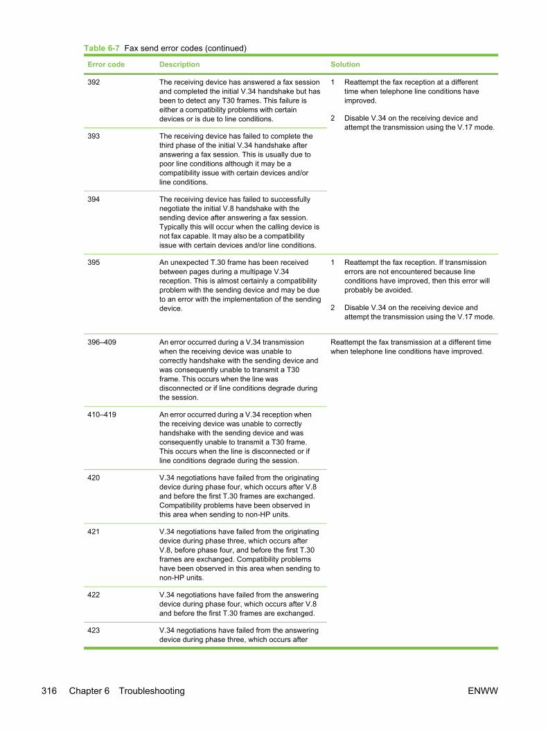
Error code Description Solution
392 The receiving device has answered a fax sessionand completed the initial V.34 handshake but hasbeen to detect any T30 frames. This failure iseither a compatibility problems with certaindevices or is due to line conditions.
1 Reattempt the fax reception at a differenttime when telephone line conditions haveimproved.
2 Disable V.34 on the receiving device andattempt the transmission using the V.17 mode.
393 The receiving device has failed to complete thethird phase of the initial V.34 handshake afteranswering a fax session. This is usually due topoor line conditions although it may be acompatibility issue with certain devices and/orline conditions.
394 The receiving device has failed to successfullynegotiate the initial V.8 handshake with thesending device after answering a fax session.Typically this will occur when the calling device isnot fax capable. It may also be a compatibilityissue with certain devices and/or line conditions.
395 An unexpected T.30 frame has been receivedbetween pages during a multipage V.34reception. This is almost certainly a compatibilityproblem with the sending device and may be dueto an error with the implementation of the sendingdevice.
1 Reattempt the fax reception. If transmissionerrors are not encountered because lineconditions have improved, then this error willprobably be avoided.
2 Disable V.34 on the receiving device andattempt the transmission using the V.17 mode.
396–409 An error occurred during a V.34 transmissionwhen the receiving device was unable tocorrectly handshake with the sending device andwas consequently unable to transmit a T30frame. This occurs when the line wasdisconnected or if line conditions degrade duringthe session.
Reattempt the fax transmission at a different timewhen telephone line conditions have improved.
410–419 An error occurred during a V.34 reception whenthe receiving device was unable to correctlyhandshake with the sending device and wasconsequently unable to transmit a T30 frame.This occurs when the line is disconnected or ifline conditions degrade during the session.
420 V.34 negotiations have failed from the originatingdevice during phase four, which occurs after V.8and before the first T.30 frames are exchanged.Compatibility problems have been observed inthis area when sending to non-HP units.
421 V.34 negotiations have failed from the originatingdevice during phase three, which occurs afterV.8, before phase four, and before the first T.30frames are exchanged. Compatibility problemshave been observed in this area when sending tonon-HP units.
422 V.34 negotiations have failed from the answeringdevice during phase four, which occurs after V.8and before the first T.30 frames are exchanged.
423 V.34 negotiations have failed from the answeringdevice during phase three, which occurs after
Table 6-7 Fax send error codes (continued)
316 Chapter 6 Troubleshooting ENWW
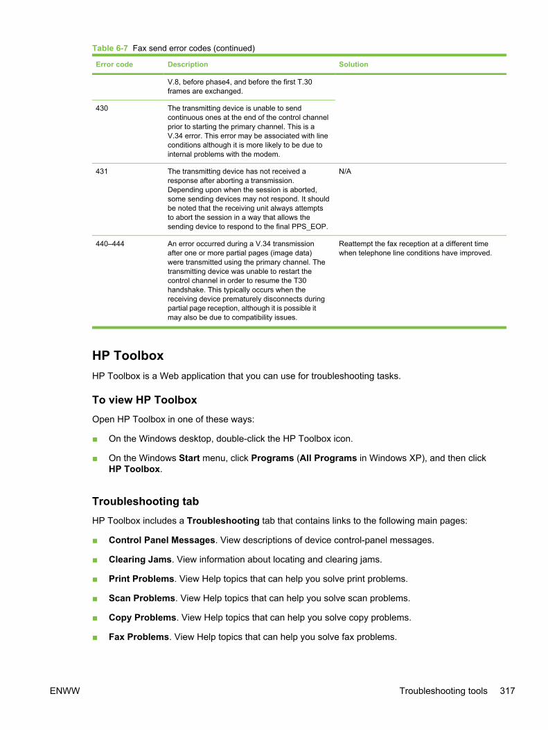
Error code Description Solution
V.8, before phase4, and before the first T.30frames are exchanged.
430 The transmitting device is unable to sendcontinuous ones at the end of the control channelprior to starting the primary channel. This is aV.34 error. This error may be associated with lineconditions although it is more likely to be due tointernal problems with the modem.
431 The transmitting device has not received aresponse after aborting a transmission.Depending upon when the session is aborted,some sending devices may not respond. It shouldbe noted that the receiving unit always attemptsto abort the session in a way that allows thesending device to respond to the final PPS_EOP.
N/A
440–444 An error occurred during a V.34 transmissionafter one or more partial pages (image data)were transmitted using the primary channel. Thetransmitting device was unable to restart thecontrol channel in order to resume the T30handshake. This typically occurs when thereceiving device prematurely disconnects duringpartial page reception, although it is possible itmay also be due to compatibility issues.
Reattempt the fax reception at a different timewhen telephone line conditions have improved.
HP ToolboxHP Toolbox is a Web application that you can use for troubleshooting tasks.
To view HP ToolboxOpen HP Toolbox in one of these ways:
■ On the Windows desktop, double-click the HP Toolbox icon.
■ On the Windows Start menu, click Programs (All Programs in Windows XP), and then clickHP Toolbox.
Troubleshooting tabHP Toolbox includes a Troubleshooting tab that contains links to the following main pages:
■ Control Panel Messages. View descriptions of device control-panel messages.
■ Clearing Jams. View information about locating and clearing jams.
■ Print Problems. View Help topics that can help you solve print problems.
■ Scan Problems. View Help topics that can help you solve scan problems.
■ Copy Problems. View Help topics that can help you solve copy problems.
■ Fax Problems. View Help topics that can help you solve fax problems.
Table 6-7 Fax send error codes (continued)
ENWW Troubleshooting tools 317
■ Memory Card Problems. View Help topics that can help you solve memory-card problems.
■ Connectivity Problems. View Help topics that can help you solve networking problems.
■ Troubleshooting Tools. Employ such troubleshooting tools as a cleaning page or a colortroubleshooting page to maintain the device.
■ Animated Demonstrations. View animated Help demonstrations for the device.
NOTE Other tabs on HP Toolbox might be helpful in troubleshooting device problems. Forinformation about the other tabs on HP Toolbox, see HP Toolbox.
Service menuUse the control-panel Service menu to troubleshoot device problems.
Restoring the factory-set defaultsRestoring the factory-set defaults returns all of the settings to the factory defaults, and it also clearsthe fax header name and phone number.
CAUTION This procedure clears fax numbers and names that are associated with one-touchkeys and speed-dial codes, and deletes any pages that are stored in the memory. Theprocedure then automatically restarts the device.
1 On the device control panel, press MENU.
2 Use the < or the > button to select Service, and then press ENTER.
3 Use the < or the > button to select Restore defaults, and then press ENTER.
The device automatically restarts.
NOTE If the Receive to PC setting is turned on, you also must delete a folder on yourcomputer to completely restore the factory-default settings. Navigate to C:\Program Files\Hewlett-Packard\Toolbox\Apache Tomcat4.0\webapps\Toolbox4.0\products\hp_color_LaserJet_2800_all_in_one\ directory and delete the FaxData folder.
NOTE You also can restore the default settings from HP Toolbox. Open HP Toolbox, clickDevice Settings, on the System Settings tab click the Service page, and then in the Resetssection click Restore.
NOTE You can save system settings before restoring the default settings from HP Toolbox.Open HP Toolbox, click Device Settings, on the System Settings tab click the Save /Restore page, and then click Save. After resetting the settings, you can restore the previoussettings by using the same page in HP Toolbox.
Cleaning the paper pathThe device features a special cleaning mode to clean the paper path.
318 Chapter 6 Troubleshooting ENWW
NOTE If you have access to HP Toolbox, HP recommends cleaning the paper path by usingHP Toolbox. See To clean the paper path from HP Toolbox.
1 On the device control panel, press MENU.
2 Use the < or the > button to select Service, and then press ENTER.
3 Use the < or the > button to select Cleaning Mode, and then press ENTER.
A page feeds through the device slowly. Discard the page when the process is completed.
4 Load plain letter or A4 paper when you are prompted.
5 Press ENTER again to confirm and begin the cleaning process.
A page feeds through the device slowly. Discard the page when the process is completed.
Setting the scanner bulb power save timeThe PowerSave time setting allows you to set the amount of time that the scanner bulb is on beforeentering the power save mode. The bulb is automatically turned on when the device is turned on, orwhen a scanner feature is started.
1 On the device control panel, press MENU.
2 Use the < or the > button to select Service, and then press ENTER.
3 Use the < or the > button to select PowerSave time, and then press ENTER.
4 Use the < or the > button to select one of the following menu items:
● 8 hours
● 12 hours
● 2 hours
● 4 hours
5 Press ENTER to save the setting.
NOTE You also can change this setting from HP Toolbox. Open HP Toolbox, clickDevice Settings, on the System Settings tab click the Service page, and then in thePower save time section use the drop-down box to set the power save time and clickApply.
Reducing paper curlThe Less paper curl setting reduces paper curl by reducing the fuser temperature.
1 On the device control panel, press MENU.
2 Use the < or the > button to select Service, and then press ENTER.
3 Use the < or the > button to select Less paper curl, and then press ENTER.
4 Use the < or the > button to select Off or On, and then press ENTER.
ENWW Troubleshooting tools 319
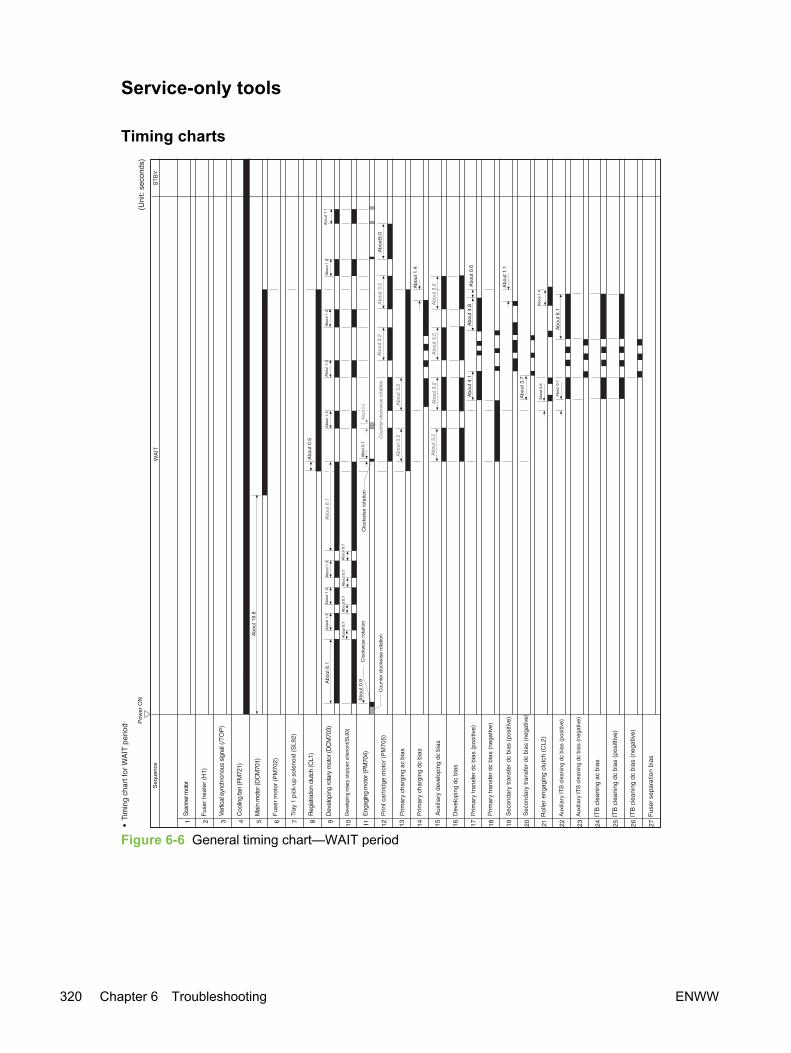
Service-only tools
Timing charts
Figure 6-6 General timing chart—WAIT period
320 Chapter 6 Troubleshooting ENWW

Figure 6-7 General timing chart—one page, full-color, normal speed
ENWW Troubleshooting tools 321

Locations of connectors
Figure 6-8 Locations of device connectors (1 of 3)
322 Chapter 6 Troubleshooting ENWW
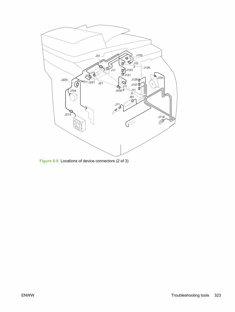
Figure 6-9 Locations of device connectors (2 of 3)
ENWW Troubleshooting tools 323
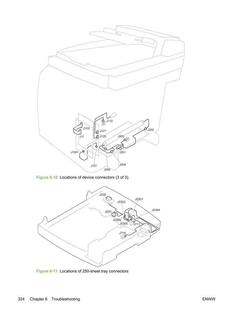
Figure 6-10 Locations of device connectors (3 of 3)
Figure 6-11 Locations of 250-sheet tray connectors
324 Chapter 6 Troubleshooting ENWW
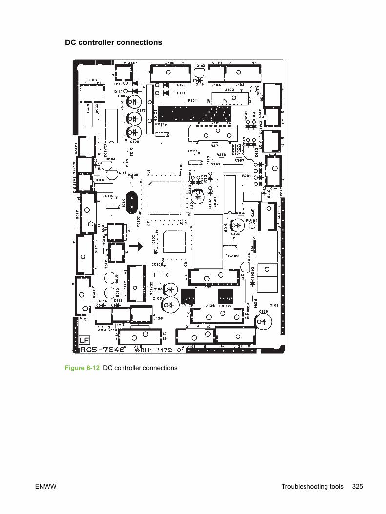
DC controller connections
Figure 6-12 DC controller connections
ENWW Troubleshooting tools 325

Printer calibrationYou can set the device to calibrate the printer manually or automatically each time the device isturned on. To calibrate the printer or to set up an automatic calibration process, complete thefollowing steps:
1 On the device control panel, press MENU.
2 Use the < or the > button to select System setup, and then press ENTER.
3 Use the < or the > button to select Print quality, and then press ENTER.
4 Use the < or the > button to select Calibrate color, and then press ENTER.
5 Use the < or the > button to select Calibrate now or After power on, and then press ENTER.
● Selecting Calibrate now starts the calibration process immediately. The control paneldisplays Calibrating until the process is complete and the device returns to the Ready state.
● Selecting After power on opens a menu that allows you to set the time period following thedevice being turned on in which you want the calibration process performed. Use the < or the> button to select one of the following menu items:
■ Immediately
■ 5 minutes
■ 15 minutes
■ 30 minutes
■ 60 minutes
■ Never
Press ENTER to save the selection.
NOTE Calibration must be performed when the device is in the Ready state. If thedevice is processing a job or if it is displaying an error message, the device will notcalibrate.
NOTE You also can perform a calibration or change the calibration settings fromHP Toolbox. Open HP Toolbox, click Device Settings, on the System Settings tab clickthe Print Quality page, and then in the Color Calibration section change the settingsand click Apply.
326 Chapter 6 Troubleshooting ENWW
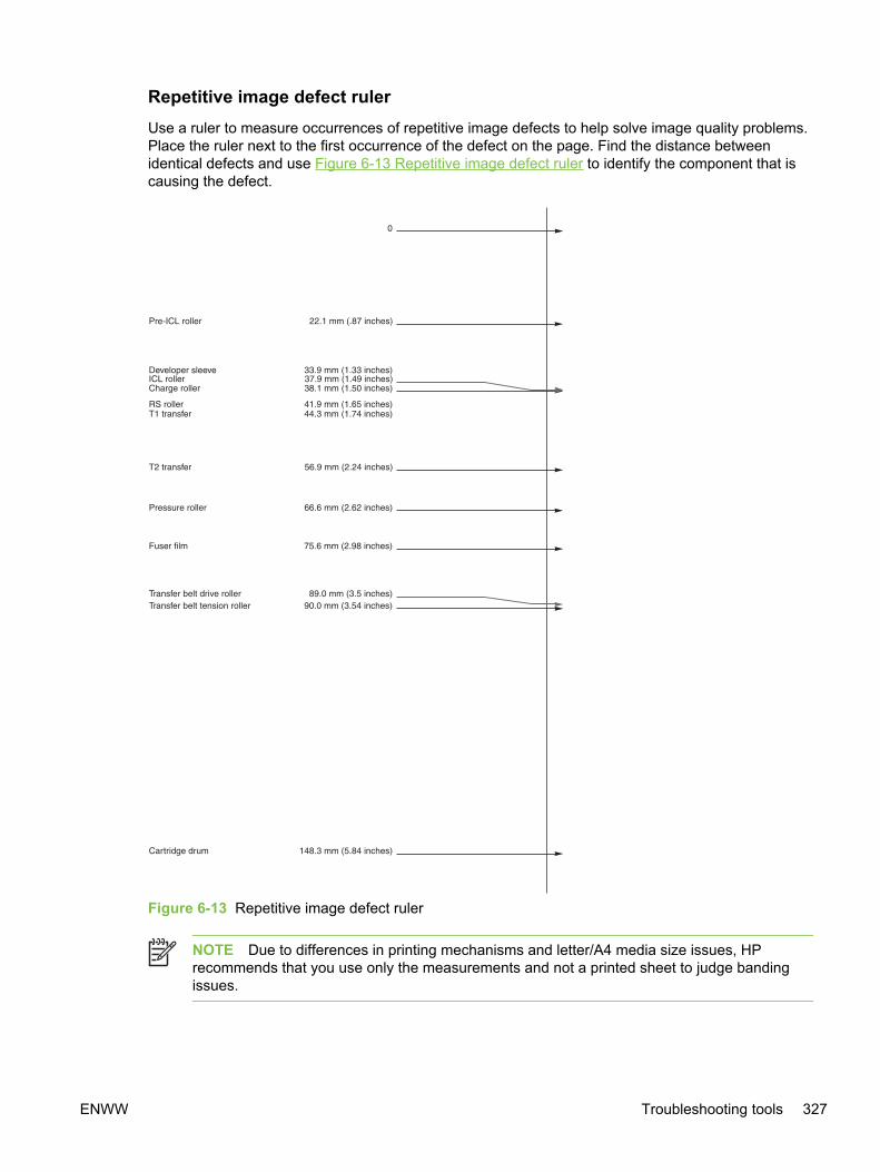
Repetitive image defect rulerUse a ruler to measure occurrences of repetitive image defects to help solve image quality problems.Place the ruler next to the first occurrence of the defect on the page. Find the distance betweenidentical defects and use Figure 6-13 Repetitive image defect ruler to identify the component that iscausing the defect.
Figure 6-13 Repetitive image defect ruler
NOTE Due to differences in printing mechanisms and letter/A4 media size issues, HPrecommends that you use only the measurements and not a printed sheet to judge bandingissues.
ENWW Troubleshooting tools 327
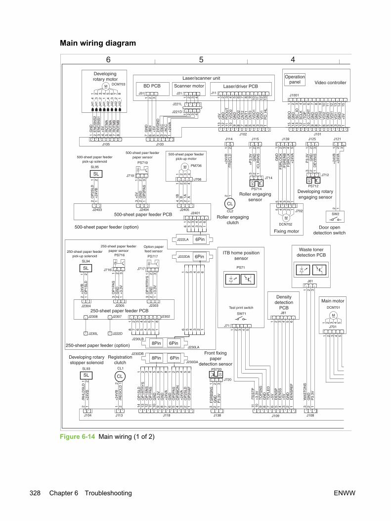
Main wiring diagram
Figure 6-14 Main wiring (1 of 2)
328 Chapter 6 Troubleshooting ENWW
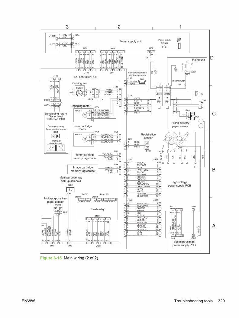
Figure 6-15 Main wiring (2 of 2)
ENWW Troubleshooting tools 329

Updating or recovering the firmware codeThe device has a flash-memory-based formatter that enables the firmware code to be updated in theevent that new firmware is released for the device. Using flash memory also provides a way torecover the firmware in the event of code corruption or failure.
Firmware update by using flash executableThe Configuration page lists the firmware version of the device. On flash-memory-based devices,you can update the firmware code by downloading the latest flash executable for the device andrunning the program according to the readme instructions that come with it. Turn the device off andthen on before running the executable file. If the firmware becomes corrupted or fails (usuallybecause of an interruption when attempting to update the firmware), the device no longer functions.In this case, a firmware-recovery DIMM is available from HP.
Firmware-recovery DIMMA firmware-recovery DIMM can be obtained from HP in the rare event that the firmware in flashmemory becomes corrupted. When the DIMM is installed in the DIMM slot on the formatter and thedevice is turned on, the DIMM loads the latest firmware code into the device.
1 Order a firmware-recovery DIMM (RDIMM) from HP.
2 Turn off the device.
3 Open the memory cover on the right side of the device, and then open the formatter cagememory door.
330 Chapter 6 Troubleshooting ENWW
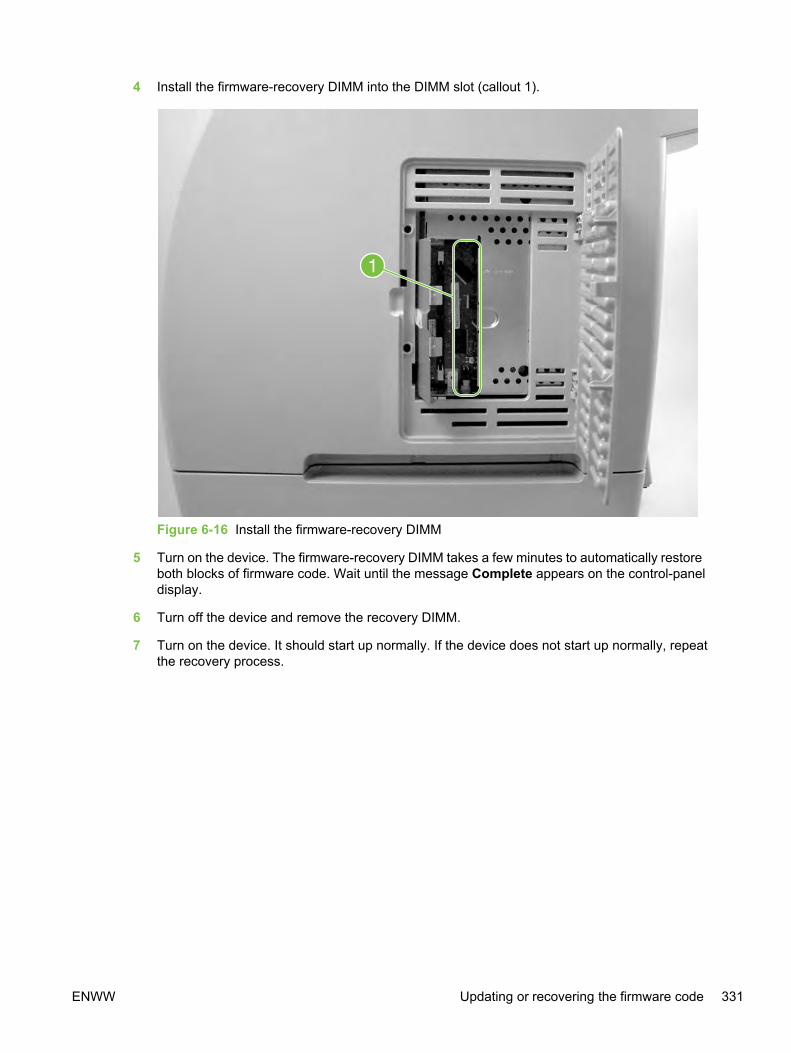
4 Install the firmware-recovery DIMM into the DIMM slot (callout 1).
Figure 6-16 Install the firmware-recovery DIMM
5 Turn on the device. The firmware-recovery DIMM takes a few minutes to automatically restoreboth blocks of firmware code. Wait until the message Complete appears on the control-paneldisplay.
6 Turn off the device and remove the recovery DIMM.
7 Turn on the device. It should start up normally. If the device does not start up normally, repeatthe recovery process.
ENWW Updating or recovering the firmware code 331

332 Chapter 6 Troubleshooting ENWW

7 Parts and diagrams
Chapter contents● Ordering parts and supplies
● Accessories
● Covers
● Internal assemblies
● Printed circuit assemblies (PCAs)
● Alphabetical parts list
● Numerical parts list
ENWW Chapter contents 333

Ordering parts and supplies
PartsOrder replacement parts from the following Web sites:
h30074.www3.hp.com/csn-aux/srvcdlvry/epdo/default/ePDOLogin.asp (technicians)
h20141.www2.hp.com/hpparts (customers)
Related documentation and softwareOrder documentation and software from the companies listed in the following table; somedocumentation and software are available at the following Web sites.
Table 7-1 Technical support Web sites
HP Customer Care Online
Software drivers, support documentation, and answers tofrequently asked questions
www.hp.com/support
HP Technical Training
(North America)
Classes and schedules
education.itrc.hp.com/TrainerII/en-US/index.jsp
SuppliesDevice supplies are listed in Table 3-1 Life expectancies of components. Consumables are availabledirectly from HP at the following numbers.
■ US: 800-538-8787
■ Canada: 800-387-3154 (in Toronto: 416-671-8383)
■ United Kingdom: 0734-441212
■ Germany: 0130-3322
Contact your local HP Parts Coordinator for other local phone numbers.
334 Chapter 7 Parts and diagrams ENWW
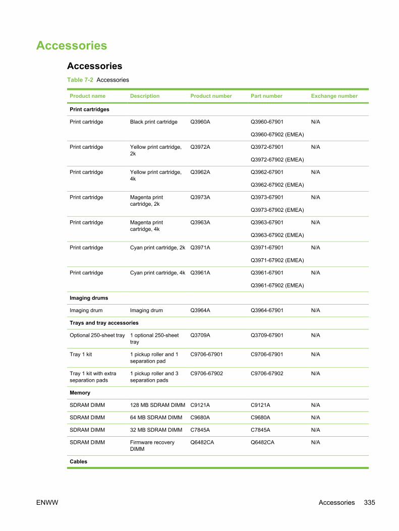
AccessoriesAccessoriesTable 7-2 Accessories
Product name Description Product number Part number Exchange number
Print cartridges
Print cartridge Black print cartridge Q3960A Q3960-67901
Q3960-67902 (EMEA)
N/A
Print cartridge Yellow print cartridge,2k
Q3972A Q3972-67901
Q3972-67902 (EMEA)
N/A
Print cartridge Yellow print cartridge,4k
Q3962A Q3962-67901
Q3962-67902 (EMEA)
N/A
Print cartridge Magenta printcartridge, 2k
Q3973A Q3973-67901
Q3973-67902 (EMEA)
N/A
Print cartridge Magenta printcartridge, 4k
Q3963A Q3963-67901
Q3963-67902 (EMEA)
N/A
Print cartridge Cyan print cartridge, 2k Q3971A Q3971-67901
Q3971-67902 (EMEA)
N/A
Print cartridge Cyan print cartridge, 4k Q3961A Q3961-67901
Q3961-67902 (EMEA)
N/A
Imaging drums
Imaging drum Imaging drum Q3964A Q3964-67901 N/A
Trays and tray accessories
Optional 250-sheet tray 1 optional 250-sheettray
Q3709A Q3709-67901 N/A
Tray 1 kit 1 pickup roller and 1separation pad
C9706-67901 C9706-67901 N/A
Tray 1 kit with extraseparation pads
1 pickup roller and 3separation pads
C9706-67902 C9706-67902 N/A
Memory
SDRAM DIMM 128 MB SDRAM DIMM C9121A C9121A N/A
SDRAM DIMM 64 MB SDRAM DIMM C9680A C9680A N/A
SDRAM DIMM 32 MB SDRAM DIMM C7845A C7845A N/A
SDRAM DIMM Firmware recoveryDIMM
Q6482CA Q6482CA N/A
Cables
ENWW Accessories 335
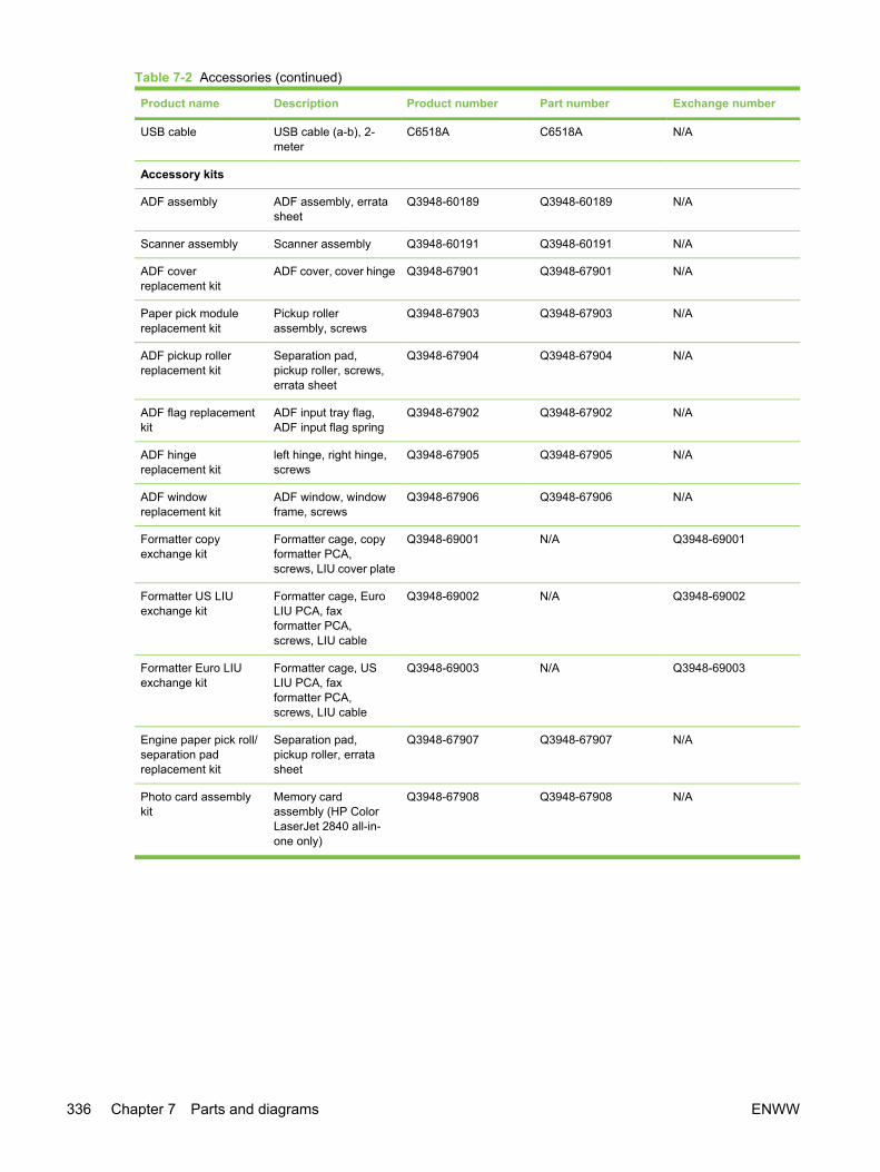
Product name Description Product number Part number Exchange number
USB cable USB cable (a-b), 2-meter
C6518A C6518A N/A
Accessory kits
ADF assembly ADF assembly, erratasheet
Q3948-60189 Q3948-60189 N/A
Scanner assembly Scanner assembly Q3948-60191 Q3948-60191 N/A
ADF coverreplacement kit
ADF cover, cover hinge Q3948-67901 Q3948-67901 N/A
Paper pick modulereplacement kit
Pickup rollerassembly, screws
Q3948-67903 Q3948-67903 N/A
ADF pickup rollerreplacement kit
Separation pad,pickup roller, screws,errata sheet
Q3948-67904 Q3948-67904 N/A
ADF flag replacementkit
ADF input tray flag,ADF input flag spring
Q3948-67902 Q3948-67902 N/A
ADF hingereplacement kit
left hinge, right hinge,screws
Q3948-67905 Q3948-67905 N/A
ADF windowreplacement kit
ADF window, windowframe, screws
Q3948-67906 Q3948-67906 N/A
Formatter copyexchange kit
Formatter cage, copyformatter PCA,screws, LIU cover plate
Q3948-69001 N/A Q3948-69001
Formatter US LIUexchange kit
Formatter cage, EuroLIU PCA, faxformatter PCA,screws, LIU cable
Q3948-69002 N/A Q3948-69002
Formatter Euro LIUexchange kit
Formatter cage, USLIU PCA, faxformatter PCA,screws, LIU cable
Q3948-69003 N/A Q3948-69003
Engine paper pick roll/separation padreplacement kit
Separation pad,pickup roller, erratasheet
Q3948-67907 Q3948-67907 N/A
Photo card assemblykit
Memory cardassembly (HP ColorLaserJet 2840 all-in-one only)
Q3948-67908 Q3948-67908 N/A
Table 7-2 Accessories (continued)
336 Chapter 7 Parts and diagrams ENWW
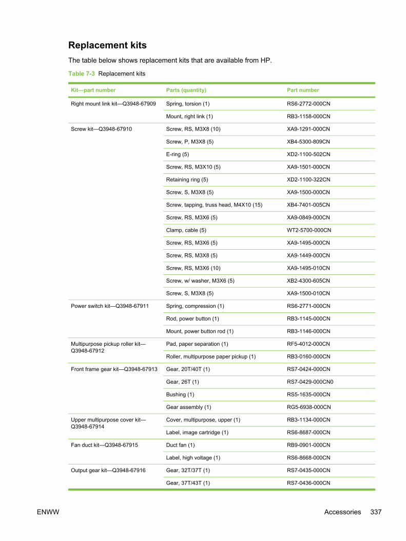
Replacement kitsThe table below shows replacement kits that are available from HP.
Table 7-3 Replacement kits
Kit—part number Parts (quantity) Part number
Right mount link kit—Q3948-67909 Spring, torsion (1) RS6-2772-000CN
Mount, right link (1) RB3-1158-000CN
Screw kit—Q3948-67910 Screw, RS, M3X8 (10) XA9-1291-000CN
Screw, P, M3X8 (5) XB4-5300-809CN
E-ring (5) XD2-1100-502CN
Screw, RS, M3X10 (5) XA9-1501-000CN
Retaining ring (5) XD2-1100-322CN
Screw, S, M3X8 (5) XA9-1500-000CN
Screw, tapping, truss head, M4X10 (15) XB4-7401-005CN
Screw, RS, M3X6 (5) XA9-0849-000CN
Clamp, cable (5) WT2-5700-000CN
Screw, RS, M3X6 (5) XA9-1495-000CN
Screw, RS, M3X8 (5) XA9-1449-000CN
Screw, RS, M3X6 (10) XA9-1495-010CN
Screw, w/ washer, M3X6 (5) XB2-4300-605CN
Screw, S, M3X8 (5) XA9-1500-010CN
Power switch kit—Q3948-67911 Spring, compression (1) RS6-2771-000CN
Rod, power button (1) RB3-1145-000CN
Mount, power button rod (1) RB3-1146-000CN
Multipurpose pickup roller kit—Q3948-67912
Pad, paper separation (1) RF5-4012-000CN
Roller, multipurpose paper pickup (1) RB3-0160-000CN
Front frame gear kit—Q3948-67913 Gear, 20T/40T (1) RS7-0424-000CN
Gear, 26T (1) RS7-0429-000CN0
Bushing (1) RS5-1635-000CN
Gear assembly (1) RG5-6938-000CN
Upper multipurpose cover kit—Q3948-67914
Cover, multipurpose, upper (1) RB3-1134-000CN
Label, image cartridge (1) RS6-8687-000CN
Fan duct kit—Q3948-67915 Duct fan (1) RB9-0901-000CN
Label, high voltage (1) RS6-8668-000CN
Output gear kit—Q3948-67916 Gear, 32T/37T (1) RS7-0435-000CN
Gear, 37T/43T (1) RS7-0436-000CN
ENWW Accessories 337
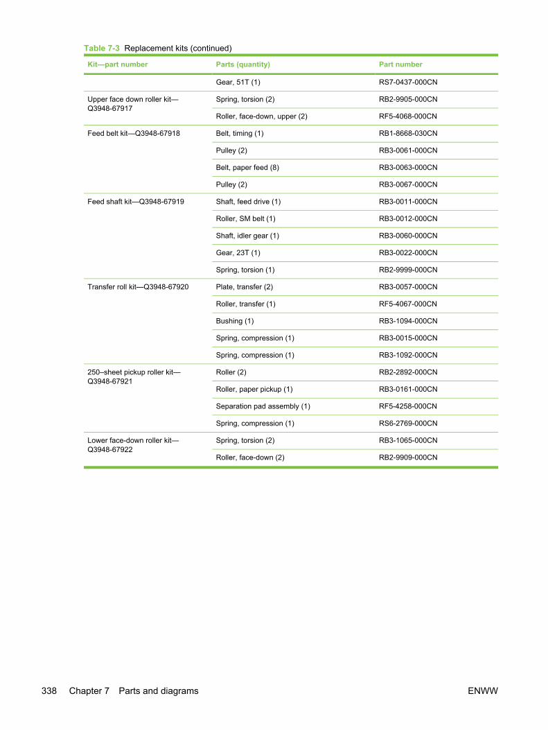
Kit—part number Parts (quantity) Part number
Gear, 51T (1) RS7-0437-000CN
Upper face down roller kit—Q3948-67917
Spring, torsion (2) RB2-9905-000CN
Roller, face-down, upper (2) RF5-4068-000CN
Feed belt kit—Q3948-67918 Belt, timing (1) RB1-8668-030CN
Pulley (2) RB3-0061-000CN
Belt, paper feed (8) RB3-0063-000CN
Pulley (2) RB3-0067-000CN
Feed shaft kit—Q3948-67919 Shaft, feed drive (1) RB3-0011-000CN
Roller, SM belt (1) RB3-0012-000CN
Shaft, idler gear (1) RB3-0060-000CN
Gear, 23T (1) RB3-0022-000CN
Spring, torsion (1) RB2-9999-000CN
Transfer roll kit—Q3948-67920 Plate, transfer (2) RB3-0057-000CN
Roller, transfer (1) RF5-4067-000CN
Bushing (1) RB3-1094-000CN
Spring, compression (1) RB3-0015-000CN
Spring, compression (1) RB3-1092-000CN
250–sheet pickup roller kit—Q3948-67921
Roller (2) RB2-2892-000CN
Roller, paper pickup (1) RB3-0161-000CN
Separation pad assembly (1) RF5-4258-000CN
Spring, compression (1) RS6-2769-000CN
Lower face-down roller kit—Q3948-67922
Spring, torsion (2) RB3-1065-000CN
Roller, face-down (2) RB2-9909-000CN
Table 7-3 Replacement kits (continued)
338 Chapter 7 Parts and diagrams ENWW
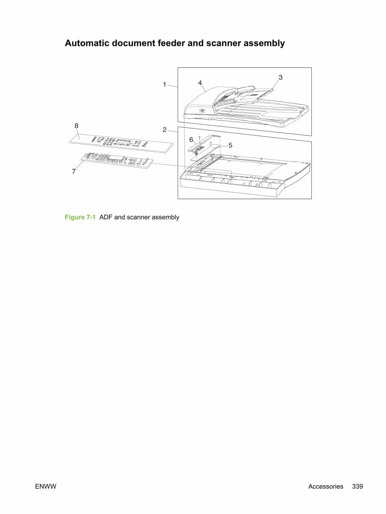
Automatic document feeder and scanner assembly
Figure 7-1 ADF and scanner assembly
ENWW Accessories 339
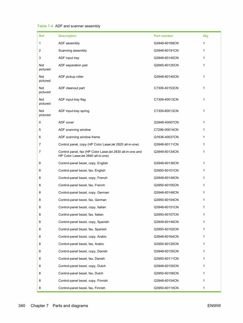
Table 7-4 ADF and scanner assembly
Ref Description Part number Qty
1 ADF assembly Q3948-60189CN 1
2 Scanning assembly Q3948-60191CN 1
3 ADF input tray Q3948-60145CN 1
Notpictured
ADF separation pad Q2665-60125CN 1
Notpictured
ADF pickup roller Q3948-60140CN 1
Notpictured
ADF cleanout part C7309-40153CN 1
Notpictured
ADF input-tray flag C7309-40013CN 1
Notpictured
ADF input-tray spring C7309-80013CN 1
4 ADF cover Q3948-40007CN 1
5 ADF scanning window C7296-00014CN 1
6 ADF scanning window frame Q1636-40037CN 1
7 Control panel, copy (HP Color LaserJet 2820 all-in-one) Q3948-60111CN 1
7 Control panel, fax (HP Color LaserJet 2830 all-in-one andHP Color LaserJet 2840 all-in-one)
Q3949-60134CN 1
8 Control-panel bezel, copy, English Q3948-60136CN 1
8 Control-panel bezel, fax, English Q3950-60101CN 1
8 Control-panel bezel, copy, French Q3948-60149CN 1
8 Control-panel bezel, fax, French Q3950-60105CN 1
8 Control-panel bezel, copy, German Q3948-60148CN 1
8 Control-panel bezel, fax, German Q3950-60104CN 1
8 Control-panel bezel, copy, Italian Q3948-60151CN 1
8 Control-panel bezel, fax, Italian Q3950-60107CN 1
8 Control-panel bezel, copy, Spanish Q3948-60146CN 1
8 Control-panel bezel, fax, Spanish Q3950-60102CN 1
8 Control-panel bezel, copy, Arabic Q3948-60164CN 1
8 Control-panel bezel, fax, Arabic Q3950-60120CN 1
8 Control-panel bezel, copy, Danish Q3948-60155CN 1
8 Control-panel bezel, fax, Danish Q3950-60111CN 1
8 Control-panel bezel, copy, Dutch Q3948-60150CN 1
8 Control-panel bezel, fax, Dutch Q3950-60106CN 1
8 Control-panel bezel, copy, Finnish Q3948-60154CN 1
8 Control-panel bezel, fax, Finnish Q3950-60110CN 1
340 Chapter 7 Parts and diagrams ENWW

Ref Description Part number Qty
8 Control-panel bezel, copy, Hebrew Q3948-60163CN 1
8 Control-panel bezel, fax, Hebrew Q3950-60119CN 1
8 Control-panel bezel, copy, Norwegian Q3948-60153CN 1
8 Control-panel bezel, fax, Norwegian Q3950-60109CN 1
8 Control-panel bezel, copy, Portuguese Q3948-60147CN 1
8 Control-panel bezel, fax, Portuguese Q3950-60103CN 1
8 Control-panel bezel, copy, Swedish Q3950-60108CN 1
8 Control-panel bezel, fax, Swedish Q3948-60152CN 1
8 Control-panel bezel, copy, Czech Q3948-60157CN 1
8 Control-panel bezel, fax, Czech Q3950-60113CN 1
8 Control-panel bezel, copy, Hungarian Q3948-60158CN 1
8 Control-panel bezel, fax, Hungarian Q3950-60114CN 1
8 Control-panel bezel, copy, Polish Q3948-60159CN 1
8 Control-panel bezel, fax, Polish Q3950-60115CN 1
8 Control-panel bezel, copy, Russian Q3948-60156CN 1
8 Control-panel bezel, fax, Russian Q3950-60112CN 1
8 Control-panel bezel, copy, Slovak Q3948-60160CN 1
8 Control-panel bezel, fax, Slovak Q3950-60116CN 1
8 Control-panel bezel, copy, Turkish Q3948-60161CN 1
8 Control-panel bezel, fax, Turkish Q3950-60117CN 1
8 Control-panel bezel, copy, Korean Q3948-60166CN 1
8 Control-panel bezel, fax, Korean Q3950-60122CN 1
8 Control-panel bezel, copy, simplified Chinese Q3948-60167CN 1
8 Control-panel bezel, fax, simplified Chinese Q3950-60123CN 1
8 Control-panel bezel, copy, traditional Chinese Q3948-60165CN 1
8 Control-panel bezel, fax, traditional Chinese Q3950-60121CN 1
8 Control-panel bezel, copy, Thai Q3948-60168CN 1
8 Control-panel bezel, fax, Thai Q3950-60124CN 1
8 Control-panel bezel, copy, Vietnamese Q3948-60169CN 1
8 Control-panel bezel, fax, Vietnamese Q3950-60125CN 1
ENWW Accessories 341
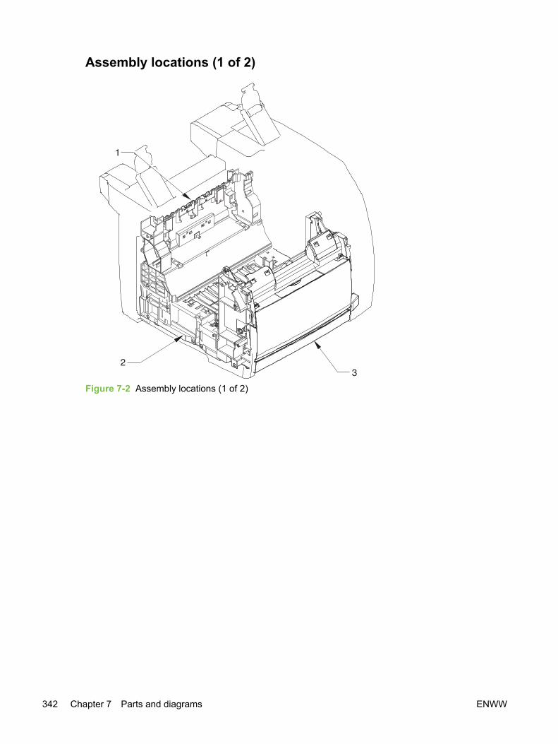
Assembly locations (1 of 2)
Figure 7-2 Assembly locations (1 of 2)
342 Chapter 7 Parts and diagrams ENWW

Table 7-5
Ref Description Part number Qty
1 Rear frame assembly See Covers 1
2 Middle frame assembly See Middle frame assembly 1
3 Front frame assembly See Front frame assembly 1
ENWW Accessories 343
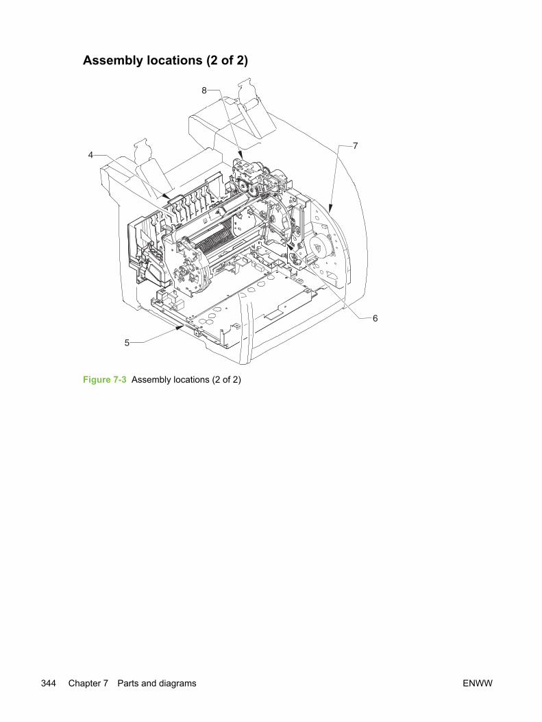
Assembly locations (2 of 2)
Figure 7-3 Assembly locations (2 of 2)
344 Chapter 7 Parts and diagrams ENWW

Table 7-6 Assembly locations (2 of 2)
Ref Description Part number Qty
4 Fuser, 110-127 V RG5-7602-000CN 1
4 Fuser, 220-240 V RG5-7603-000CN 1
1 Power-supply base assembly See Power-supply baseassembly
1
1 Rotary assembly RG5-7587-000CN 1
1 Main drive assembly RG5-7579-000CN 1
1 Rotary drive assembly RG5-7592-000CN 1
ENWW Accessories 345

Covers
Figure 7-4 Covers
346 Chapter 7 Parts and diagrams ENWW

Table 7-7 Covers
Ref Description Part number Qty
1 Cover, rear RB3-1130-000CN 1
2 Spring, torsion RS6-2772-000CN 1
3 Cover, top (assembly) RG5-7597-000CN 1
3A Cover, rack RB3-0089-030CN 1
3B Cover, cartridge RF5-4055-000CN 1
4 Cover, face-down RB3-1136-000CN 1
5 Right cover assembly RG5-7599-000CN 1
5A Cover, memory RB3-1138-000CN 1
6 Link unit, left RG5-7645-000CN 1
7 Left cover assembly RG5-7598-000CN 1
7A Spring, compression RS6-2771-000CN 1
7B Rod, power button RB3-1145-000CN 1
7C Cover, left RB3-1128-000CN 1
7D Cover, vent RB3-1139-000CN 1
7E Mount, power button rod RB3-1146-000CN 1
8 Screw, RS, M3x8 XA9-1291-000CN 7
9 Cover, left upper RB3-1126-000CN 1
10 Cover, left rear RB3-1131-000CN 1
11 Cover, right rear RB3-1132-000CN 1
12 Cover, I/O RB3-1137-000CN 1
13 Foot, fall prevention RB3-1147-000CN 1
14 Mount, left link RB3-1154-000CN 1
15 Mount, right link RB3-1158-000CN 1
16 Cover, front RB3-1125-000CN 1
17 Arm, face-down RB3-1083-000CN 2
18 Link unit, right RG5-7630-000CN 1
501 Screw, P, M3x8 XB4-5300-809CN 2
502 Screw, tapping, truss head, M4X10 XB4-7401-005CN 2
A01 Cover, top
A02 Cover, right
A03 Button, power
A04 Cover, cartridge
A05 Sheet, noise-proof rubber
A06 Label, I/O operation
ENWW Covers 347

Ref Description Part number Qty
A07 Plate, interlock switch shield
A08 Plate, static eliminator
A09 Guide, cable
A10 Label, CRG
A11 Plate, formatter grounding
348 Chapter 7 Parts and diagrams ENWW

ENWW Covers 349

Internal assemblies
Figure 7-5 Front frame assembly
350 Chapter 7 Parts and diagrams ENWW

Table 7-8 Front frame assembly
Ref Description Part number Qty
1 Spring, torsion RB2-9952-000CN 1
2 Hinge, multipurpose, right RB9-0890-000CN 1
3 Hinge, multipurpose, left RB9-0889-000CN 1
4 Bushing, left RB2-3043-000CN 1
5 Bushing, right RB2-3044-000CN 1
6 Damper assembly RB2-6248-000CN 1
7 Cover, multipurpose, upper RB3-1134-000CN 1
8 Cover, multipurpose, lower RB3-1135-000CN 1
9 Cover, multipurpose, roller RB3-0104-000CN 1
10 Flag, multipurpose sensor RB3-0111-000CN 1
11 Cable, waste toner RG5-7624-000CN 1
12 Cover, MP. gauss blocking RB3-0120-000CN 1
13 Spring, torsion RB3-0121-000CN 1
14 Spring, torsion RB3-0122-000CN 1
15 Flag, test print switch RB3-0135-000CN 1
16 Solenoid RH7-5383-000CN 1
17 Pad, paper separation RF5-4012-000CN 1
18 Spring, tension RS6-2030-000CN 2
19 Gear, 26T RS7-0418-000CN 1
20 Gear, 20T/40T RS7-0424-000CN 1
21 Gear, 26T/50T RS7-0426-000CN 1
22 Gear, 26T RS7-0429-000CN 1
23 Photo interrupter TLP1242 WG8-5593-000CN 1
24 Screw, tapping, truss head, M4X10 XB4-7401-005CN 11
25 Multipurpose cover assembly RG5-7601-000CN 1
26 Gear assembly RG5-6938-000CN 1
27 Multipurpose inner plate assembly RG5-7584-000CN 1
28 Multipurpose paper pickup roller assembly RG5-6952-000CN 1
28A Roller, multipurpose paper pickup RB3-0160-000CN 1
29 Clamp, cable WT2-5700-000CN 2
30 Tag contact PCA RG5-7131-000CN 1
31 Clip, cable WT2-5056-000CN 1
32 Gear, 30T RS7-0425-000CN 1
33 Bushing RS5-1635-000CN 1
ENWW Internal assemblies 351
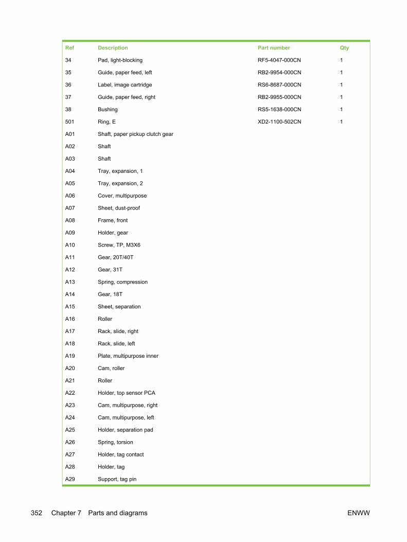
Ref Description Part number Qty
34 Pad, light-blocking RF5-4047-000CN 1
35 Guide, paper feed, left RB2-9954-000CN 1
36 Label, image cartridge RS6-8687-000CN 1
37 Guide, paper feed, right RB2-9955-000CN 1
38 Bushing RS5-1638-000CN 1
501 Ring, E XD2-1100-502CN 1
A01 Shaft, paper pickup clutch gear
A02 Shaft
A03 Shaft
A04 Tray, expansion, 1
A05 Tray, expansion, 2
A06 Cover, multipurpose
A07 Sheet, dust-proof
A08 Frame, front
A09 Holder, gear
A10 Screw, TP, M3X6
A11 Gear, 20T/40T
A12 Gear, 31T
A13 Spring, compression
A14 Gear, 18T
A15 Sheet, separation
A16 Roller
A17 Rack, slide, right
A18 Rack, slide, left
A19 Plate, multipurpose inner
A20 Cam, roller
A21 Roller
A22 Holder, top sensor PCA
A23 Cam, multipurpose, right
A24 Cam, multipurpose, left
A25 Holder, separation pad
A26 Spring, torsion
A27 Holder, tag contact
A28 Holder, tag
A29 Support, tag pin
352 Chapter 7 Parts and diagrams ENWW

Ref Description Part number Qty
A30 Pin, tag
A31 Spring, compression
A32 Pin, dowel
ENWW Internal assemblies 353

Figure 7-6 Internal components (1 of 2)
354 Chapter 7 Parts and diagrams ENWW
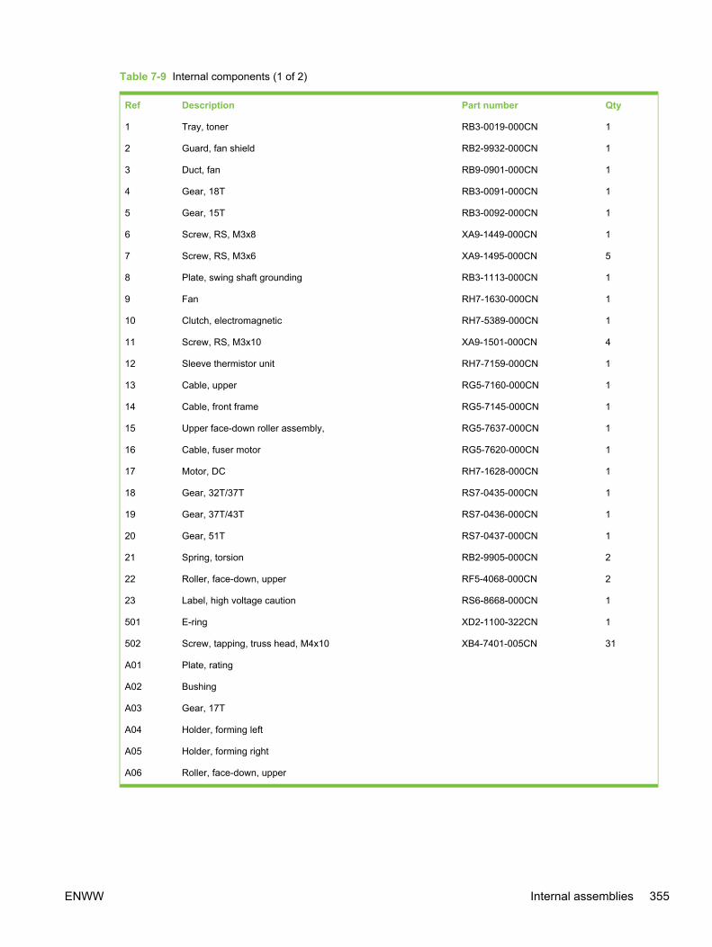
Table 7-9 Internal components (1 of 2)
Ref Description Part number Qty
1 Tray, toner RB3-0019-000CN 1
2 Guard, fan shield RB2-9932-000CN 1
3 Duct, fan RB9-0901-000CN 1
4 Gear, 18T RB3-0091-000CN 1
5 Gear, 15T RB3-0092-000CN 1
6 Screw, RS, M3x8 XA9-1449-000CN 1
7 Screw, RS, M3x6 XA9-1495-000CN 5
8 Plate, swing shaft grounding RB3-1113-000CN 1
9 Fan RH7-1630-000CN 1
10 Clutch, electromagnetic RH7-5389-000CN 1
11 Screw, RS, M3x10 XA9-1501-000CN 4
12 Sleeve thermistor unit RH7-7159-000CN 1
13 Cable, upper RG5-7160-000CN 1
14 Cable, front frame RG5-7145-000CN 1
15 Upper face-down roller assembly, RG5-7637-000CN 1
16 Cable, fuser motor RG5-7620-000CN 1
17 Motor, DC RH7-1628-000CN 1
18 Gear, 32T/37T RS7-0435-000CN 1
19 Gear, 37T/43T RS7-0436-000CN 1
20 Gear, 51T RS7-0437-000CN 1
21 Spring, torsion RB2-9905-000CN 2
22 Roller, face-down, upper RF5-4068-000CN 2
23 Label, high voltage caution RS6-8668-000CN 1
501 E-ring XD2-1100-322CN 1
502 Screw, tapping, truss head, M4x10 XB4-7401-005CN 31
A01 Plate, rating
A02 Bushing
A03 Gear, 17T
A04 Holder, forming left
A05 Holder, forming right
A06 Roller, face-down, upper
ENWW Internal assemblies 355

Figure 7-7 Internal components (2 of 2)
356 Chapter 7 Parts and diagrams ENWW

Table 7-10 Internal components (2 of 2)
Ref Description Part number Qty
1 Flat cable, laser RH2-5524-000CN 1
2 Holder, interlock switch RB3-0023-000CN 1
3 Scanner crossmember assembly RG5-6907-000CN 1
4 Cable guide RB2-9903-000CN 1
5 Laser/scanner RG5-6890-000CN 1
6 Screw, RS, M3x6 XA9-0849-000CN 18
7 Cable, motor RG5-7114-000CN 1
8 Guide, rotary release RB2-9852-000CN 1
9 Microswitch RH7-6051-000CN 1
10 Left cartridge guide assembly RG5-6935-000CN 1
11 Cable, sensor RG5-7117-000CN 1
12 Right support assembly RG5-7631-000CN 1
13 Left support assembly RG5-7632-000CN 1
14 Plate, photo card crossmember RB2-9976-000CN 1
15 Screw, RS, M3x6 XA9-1495-000CN 15
16 Sheet, protective, A RB3-1379-000CN 1
17 Sheet, protective, B RB3-1380-000CN 1
A01 Crossmember, scanner
A02 Arm, shutter
A03 Crossmember, beam
A04 Spring, compression
A05 Left side plate assembly
A06 Spring, torsion
A07 Spring, torsion
A08 Gear, 34T
A09 Side plate, left
A10 Sheet
A11 Screw, RS, M3X6
A12 Guide, left cartridge
A13 Shaft, gear
A14 Cover, edge
A15 Plate, photo card mounting
ENWW Internal assemblies 357

Figure 7-8 Rear frame assembly
358 Chapter 7 Parts and diagrams ENWW

Table 7-11 Rear frame assembly
Ref Description Part number Qty
1 Duct, fuser RB2-9904-000CN 1
2 Lower face-down roller assembly RG5-7595-000CN 1
3 Spring, torsion RB3-1065-000CN 2
4 Screw, RS, M3x6 XA9-0849-000CN 2
5 Roller, face-down, lower RB2-9909-000CN 2
6 Cover, pressure motor RB2-9916-000CN 1
7 Motor, DC, 24 V RH7-1629-000CN 1
501 Screw, tapping, truss head, M4x10 XB4-7401-005CN 3
A01 Gear, 17T
A02 Roller, face-down
A03 Bushing
A04 Frame, rear
ENWW Internal assemblies 359

Figure 7-9 Middle frame assembly
360 Chapter 7 Parts and diagrams ENWW

Table 7-12 Middle frame assembly
Ref Description Part number Qty
1 Timing belt RB1-8668-030CN 1
2 Pulley RB3-0061-000CN 2
3 Paper feed belt RB3-0063-000CN 8
4 Rubber foot RB2-6297-000CN 2
5 Roller grounding plate RB3-0286-000CN 1
6 Static charge eliminator plate RB3-0009-000CN 1
7 Paper feed plate RB3-0010-000CN 1
8 Shaft, feed drive RB3-0011-000CN 1
9 Roller, belt RB3-0012-000CN 1
10 Shaft, idler gear RB3-0060-000CN 1
11 Spring, torsion RB3-0045-000CN 1
12 Spring, torsion RB3-0016-000CN 1
13 Gear, 23T RB3-0022-000CN 1
14 Spring, torsion RB3-0042-000CN 1
15 Spring, torsion RB3-0043-000CN 1
16 Spring, torsion RB3-0044-000CN 1
17 Spring, torsion RB3-0046-000CN 1
18 Spring, torsion RB3-0047-000CN 1
19 Spring, torsion RB3-0048-000CN 1
20 Bushing RS5-1637-000CN 1
21 Insulating sheet RB3-1110-000CN 1
22 Transfer slide plate RB3-0057-000CN 2
23 Drawer connector WS1-6336-000CN 1
24 Gear, 30T RS7-0428-000CN 1
25 Entrance guide assembly RF5-4065-000CN 1
26 Registration roller assembly RG5-6939-000CN 1
27 Cable, grounding RG5-7123-000CN 1
28 Registration shutter assembly RG5-6940-000CN 1
29 Cable, interface RG5-7122-000CN 1
30 Cover, gear RB3-0052-000CN 1
31 Grounding spring RB3-0065-000CN 1
32 Grounding spring RB3-0066-000CN 1
33 Sensor flag arm RB2-9925-000CN 1
34 Holder, transfer sensor RB2-9924-000CN 1
ENWW Internal assemblies 361

Ref Description Part number Qty
35 Roller, transfer sensor RB2-7195-000CN 1
36 Pulley RB3-0067-000CN 2
37 Paper sensor cable RG5-7128-000CN 1
38 Photo interrupter TLP1242 WG8-5593-000CN 1
39 Spring, tension RS6-2766-000CN 1
40 Mount, terminal RB2-9850-000CN 1
41 Mount, antenna contact RB2-9851-000CN 1
42 Clip, cable WT2-5610-000CN 2
43 Cable, high-voltage transformer RG5-7130-000CN 1
44 Clamp, cable WT2-5700-000CN 1
45 Spring, torsion RB2-9999-000CN 1
46 Roller, transfer RF5-4067-000CN 1
47 Bushing RB3-1094-000CN 1
48 Spring, compression RB3-1091-000CN 1
49 Spring, compression RB3-1092-000CN 1
50 Spring, compression RB3-0015-000CN 1
51 Resistor, 500MOHM, 0.3W RH5-3169-000CN 1
52 Guide, transfer inlet RB3-1088-000CN 1
501 Screw, tapping, truss head, M4x10 XB4-7401-005CN 13
502 Screw, w/washer, M3x6 XB2-4300-605CN 2
A01 Spring, torsion
A02 Bushing
A03 Flag, registration-sensor
A04 Registration roller
A05 Registration holder
A06 Registration front guide
A07 Registration shutter
A08 Registration roller
A09 Registration roller shaft
A10 Spring, torsion
A11 Bushing
A12 Spring, compression
A13 Registration pressure arm
A14 Middle frame
A15 Screw, B, M3x8
362 Chapter 7 Parts and diagrams ENWW

Ref Description Part number Qty
A16 Spring, compression
A17 Gear, 26T/34T
ENWW Internal assemblies 363

Figure 7-10 Power-supply base assembly
364 Chapter 7 Parts and diagrams ENWW

Table 7-13 Power-supply base assembly
Ref Description Part number Qty
1 Holder, fuser connector RB3-0006-000CN 1
2 Insulating sheet RB3-0007-000CN 1
3 Support, high-voltage PCA VT2-0012-005CN 6
4 Cable, high-voltage transformer RG5-7146-000CN 1
5 Clip, cable WT2-5737-000CN 2
6 Screw, RS, M3x8 XA9-1449-000CN 9
7 Cable, sub-high-voltage transformer RG5-7126-000CN 1
8 Cable, fuser connector, DC controller RG5-7109-000CN 1
9 Cable, fuser, power RG5-7161-000CN 1
10 Cable, video interface, power RG5-7106-000CN 1
11 Cable, power (1) RG5-7621-000CN 1
12 Cable, power (2) RG5-7108-000CN 1
13 Holder, high-voltage RB3-0062-000CN 1
14 Screw, S, M3x8 XA9-1500-000CN 4
15 Cable, formatter RG5-7156-000CN 1
A01 Crossmember, power supply base
ENWW Internal assemblies 365
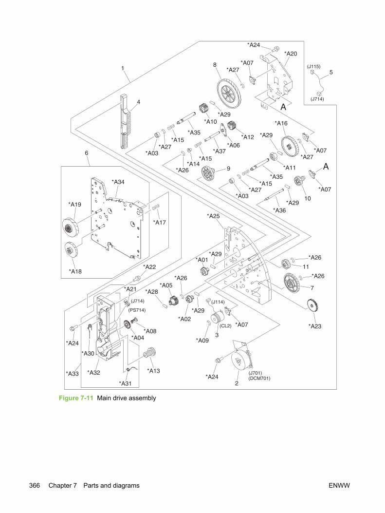
Figure 7-11 Main drive assembly
366 Chapter 7 Parts and diagrams ENWW

Table 7-14 Main drive assembly
Ref Description Part number Qty
Main drive assembly RG5-7579-000CN 1
1 Right side plate front assembly RG5-7581-000CN 1
2 Motor unit RF5-4063-000CN 1
3 Clutch, electromagnetic RH7-5335-000CN 1
4 Rack RB3-0090-000CN 1
5 Cable, second, transfer sensor RG5-7115-000CN 1
6 Right side plate rear assembly RG5-7580-000CN 1
7 Gear, 32T/123T RS7-0574-000CN 1
8 Gear, 186T RS7-0573-000CN 1
9 Gear, 31T/90T RS7-0572-000CN 1
10 Gear, 23T/54T RS7-0571-000CN 1
11 Gear, 81T RS7-0570-000CN 1
A01 Coupling, drum
A02 Coupling, ITB
A03 Support, spring
A04 Gear, 35T
A05 Gear, 35T
A06 Bushing, gear drive shaft
A07 Bushing, IS drive shaft
A08 Pin, support
A09 E-ring
A10 Gear, 13T
A11 Gear, 13T
A12 Gear, 12T
A13 Gear, 21T/35T
A14 Support, spring
A15 Spring, compression
A16 Gear, 138T
A17 Spring, grounding
A18 Gear, 17T/98T
A19 Gear, 120T/20T
A20 Side plate, right rear
A21 Photo interrupter TLP1242
A22 Screw, S, M3X8
ENWW Internal assemblies 367

Ref Description Part number Qty
A23 Gear, 64T
A24 Screw, RS, M3X6
A25 Side plate, right front
A26 E-ring
A27 E-ring
A28 Pin, dowel
A29 Pin, dowel
A30 Spring, torsion
A31 Spring, torsion
A32 Guide, right cartridge
A33 Right cartridge guide assembly
A34 Side plate, right rear
A35 Shaft, main drive
A36 Shaft, image drive
A37 Shaft, gear drive
368 Chapter 7 Parts and diagrams ENWW

ENWW Internal assemblies 369
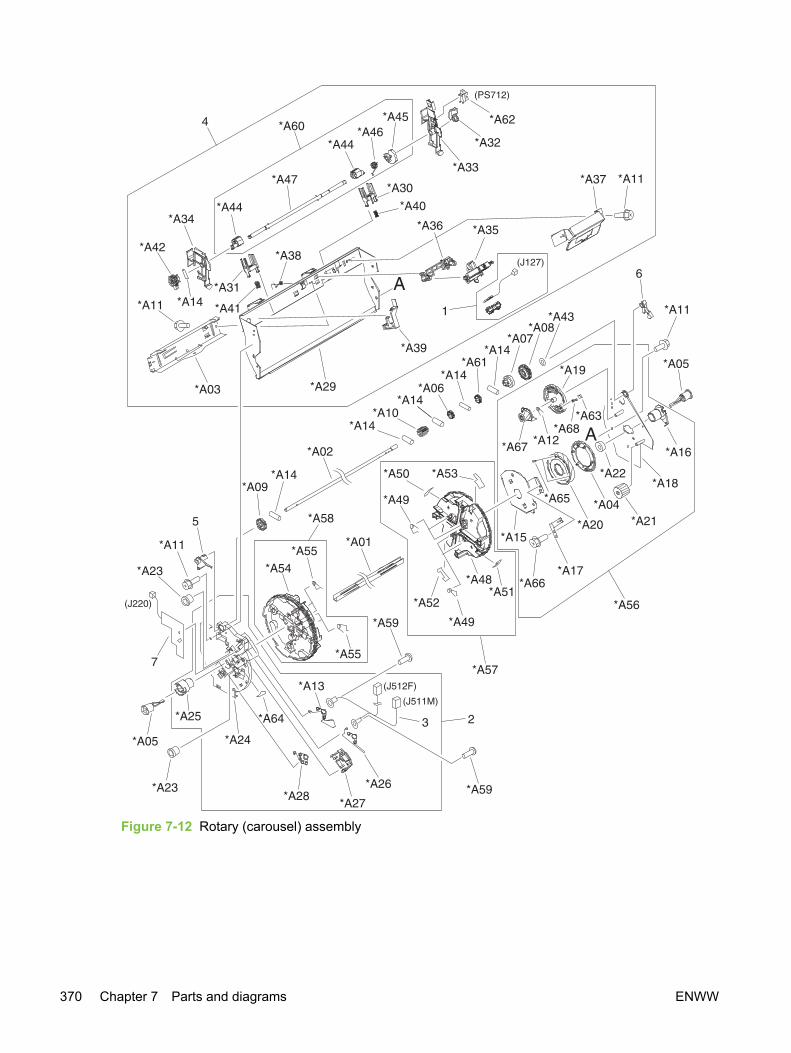
Figure 7-12 Rotary (carousel) assembly
370 Chapter 7 Parts and diagrams ENWW
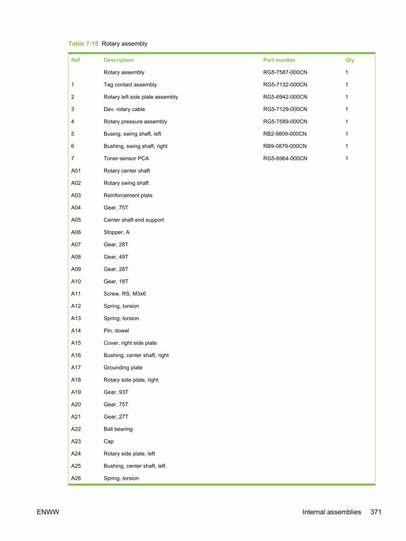
Table 7-15 Rotary assembly
Ref Description Part number Qty
Rotary assembly RG5-7587-000CN 1
1 Tag contact assembly RG5-7132-000CN 1
2 Rotary left side plate assembly RG5-6942-000CN 1
3 Dev. rotary cable RG5-7129-000CN 1
4 Rotary pressure assembly RG5-7589-000CN 1
5 Busing, swing shaft, left RB2-9809-000CN 1
6 Bushing, swing shaft, right RB9-0879-000CN 1
7 Toner-sensor PCA RG5-6964-000CN 1
A01 Rotary center shaft
A02 Rotary swing shaft
A03 Reinforcement plate
A04 Gear, 75T
A05 Center shaft end support
A06 Stopper, A
A07 Gear, 28T
A08 Gear, 49T
A09 Gear, 28T
A10 Gear, 18T
A11 Screw, RS, M3x6
A12 Spring, torsion
A13 Spring, torsion
A14 Pin, dowel
A15 Cover, right side plate
A16 Bushing, center shaft, right
A17 Grounding plate
A18 Rotary side plate, right
A19 Gear, 93T
A20 Gear, 75T
A21 Gear, 27T
A22 Ball bearing
A23 Cap
A24 Rotary side plate, left
A25 Bushing, center shaft, left
A26 Spring, torsion
ENWW Internal assemblies 371

Ref Description Part number Qty
A27 Plate, spring positioning
A28 Spring, torsion
A29 Crossmember, rotary pressure
A30 Support, spring, right
A31 Support, spring, left
A32 Flag, pressure shaft
A33 Holder, pressure shaft, right
A34 Holder, pressure shaft, left
A35 Holder, tag contact
A36 Support, tag contact
A37 Plate, tag contact
A38 Spring, torsion
A39 Plate, pressure lock
A40 Spring, compression
A41 Spring, compression
A42 Gear, 25T
A43 Washer
A44 Cam, pressure
A45 Cam, tag contact drive
A46 Spring, torsion
A47 Shaft, rotary pressure
A48 Disc, rotary right
A49 Spring, torsion
A50 Label, rotary inlet
A51 Label, rotary inlet
A52 Label, rotary inlet
A53 Label, rotary inlet
A54 Disc, rotary left
A55 Spring, torsion
A56 Rotary right side plate assembly
A57 Rotary right disc assembly
A58 Rotary left disc assembly
A59 Screw, w/washer, M3x6
A60 Rotary pressure shaft assembly
A61 Stopper, B
372 Chapter 7 Parts and diagrams ENWW

Ref Description Part number Qty
A62 Photo interrupter, TLP1242
A63 Pin, silencer
A64 Sheet, discharge
A65 Spring
A66 Screw, TP, M3x4
A67 Gear, 19T
A68 Plate, silencer pin
ENWW Internal assemblies 373
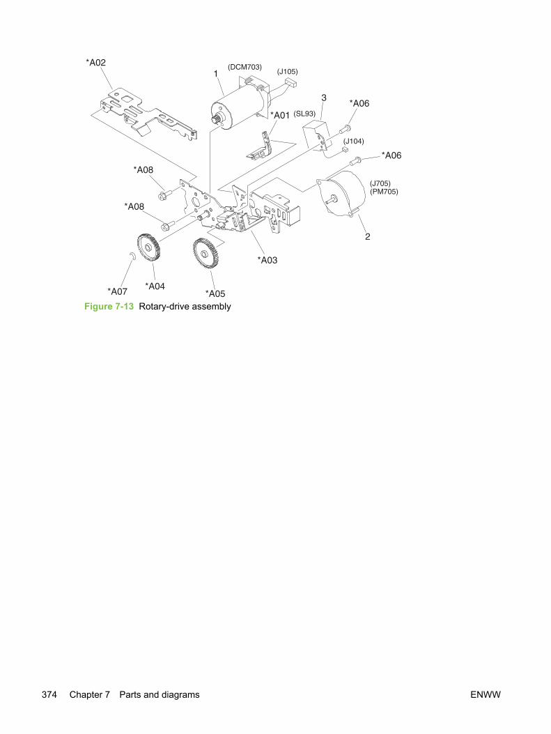
Figure 7-13 Rotary-drive assembly
374 Chapter 7 Parts and diagrams ENWW

Table 7-16 Rotary-drive assembly
Ref Description Part number Qty
Rotary drive assembly RG5-7842-000CN 1
1 Motor unit RH7-1651-000CN 1
2 Motor (DC 24V) RH7-1625-000CN 1
3 Solenoid RH7-5384-000CN 1
A01 Guide, rotary drive
A02 Cover, mount motor
A03 Mount, motor
A04 Gear, 20T/70T
A05 Gear, 48T
A06 Screw, TP, M3x4
A07 E-ring
A08 Screw, RS, M3x6
ENWW Internal assemblies 375

Figure 7-14 Fuser assembly
376 Chapter 7 Parts and diagrams ENWW

Table 7-17 Fuser assembly
Ref Description Part number Qty
Fuser assembly, 110–127V RG5-7602-000CN 1
Fuser assembly, 220–240V RG5-7603-000CN 1
1 Bushing RB3-1026-000CN 1
2 Bushing RB3-1027-000CN 1
3 Lever, lock release, right RB3-0178-000CN 1
4 Lever, lock release, left RB3-0179-000CN 1
5 Guide, paper inlet RB3-0180-000CN 1
6 Pressure plate RB3-1024-000CN 2
7 High-temperature caution label RU5-8125-000CN 1
8 Roller, pressure RB3-1034-000CN 1
9 Screw, RS, M3x8 XA9-1500-000CN 4
10 Base plate, fixing RF5-4060-000CN 1
11 Spring, compression RB3-1025-000CN 2
12 Gear, 30T RS7-0580-000CN 1
13 Clamp, cable WT2-5700-000CN 1
14 Fuser film assembly RG5-7162-000CN 1
14 Fuser film assembly RG5-7163-000CN 1
15 Separation upper guide assembly RG5-7576-000CN 1
15A Roller, delivery RB2-9950-000CN 2
16 Lever, pressure-release, right RB3-1166-000CN 1
17 Face-up cover assembly RG5-7604-000CN 1
17A Cover, face-up, upper RB3-1140-000CN 1
18 Separation lower guide assembly RG5-7577-000CN 1
19 Lever, pressure-release, left RB3-1167-000CN 1
20 Spring, grounding RB3-1150-000CN 2
21 Holder, delivery idle gear shaft RB3-1029-000CN 1
22 Cover, fuser, upper RB3-1032-000CN 1
23 Shaft, lever RB2-4933-000CN 2
24 Cable, fuser AC RG5-7154-000CN 1
24 Cable, fuser AC RG5-7155-000CN 1
25 Gear, 28T RS7-0582-000CN 1
26 Screw, RS, M3x8 XA9-1449-000CN 2
27 Spacer, right RB2-9934-000CN 1
28 Spacer, left RB2-9935-000CN 1
ENWW Internal assemblies 377

Ref Description Part number Qty
A01 Frame, fuser
A02 Spring, torsion
A03 Cover, face-up, lower
A04 Guide, upper separation
A05 Guide, lower separation
A06 Flag, paper-delivery sensor
A07 Spring, torsion
A08 Bushing
A09 Roller, paper-delivery
A10 Spring, torsion
A11 Lever, pressure-release sensor, right
A12 Gear, 17T
A13 Lever, pressure-release sensor, left
A14 Photo interrupter, TLP1242
A15 Frame, separation, lower
A16 Screw, with washer, M4x12
378 Chapter 7 Parts and diagrams ENWW

ENWW Internal assemblies 379

Printed circuit assemblies (PCAs)
Figure 7-15 PCAs
380 Chapter 7 Parts and diagrams ENWW

Table 7-18 PCA assemblies
Ref Description Part number Qty
1 Top sensor PCA RG5-7612-000CN 1
2 DC Controller PCA RG5-7646-000CN 1
3 Low-voltage PCA, 110-127 V RH3-2260-000CN 1
3 Low-voltage PCA, 220-240 V RH3-2261-000CN 1
4 High-voltage transformer PCA RG5-7647-000CN 1
5 Waste-toner sensor PCA RG5-7648-000CN 1
6 Registration-sensor PCA RG5-7613-000CN 1
7 Density-sensor PCA RH7-7158-000CN 1
8 Toner-sensor PCA RG5-7609-000CN 1
9 Sub-high-voltage transformer PCA RG5-7616-000CN 1
ENWW Printed circuit assemblies (PCAs) 381
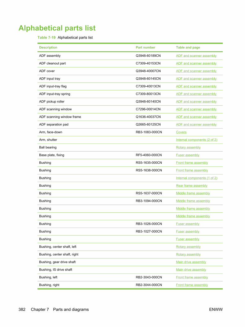
Alphabetical parts listTable 7-19 Alphabetical parts list
Description Part number Table and page
ADF assembly Q3948-60189CN ADF and scanner assembly
ADF cleanout part C7309-40153CN ADF and scanner assembly
ADF cover Q3948-40007CN ADF and scanner assembly
ADF input tray Q3948-60145CN ADF and scanner assembly
ADF input-tray flag C7309-40013CN ADF and scanner assembly
ADF input-tray spring C7309-80013CN ADF and scanner assembly
ADF pickup roller Q3948-60140CN ADF and scanner assembly
ADF scanning window C7296-00014CN ADF and scanner assembly
ADF scanning window frame Q1636-40037CN ADF and scanner assembly
ADF separation pad Q2665-60125CN ADF and scanner assembly
Arm, face-down RB3-1083-000CN Covers
Arm, shutter Internal components (2 of 2)
Ball bearing Rotary assembly
Base plate, fixing RF5-4060-000CN Fuser assembly
Bushing RS5-1635-000CN Front frame assembly
Bushing RS5-1638-000CN Front frame assembly
Bushing Internal components (1 of 2)
Bushing Rear frame assembly
Bushing RS5-1637-000CN Middle frame assembly
Bushing RB3-1094-000CN Middle frame assembly
Bushing Middle frame assembly
Bushing Middle frame assembly
Bushing RB3-1026-000CN Fuser assembly
Bushing RB3-1027-000CN Fuser assembly
Bushing Fuser assembly
Bushing, center shaft, left Rotary assembly
Bushing, center shaft, right Rotary assembly
Bushing, gear drive shaft Main drive assembly
Bushing, IS drive shaft Main drive assembly
Bushing, left RB2-3043-000CN Front frame assembly
Bushing, right RB2-3044-000CN Front frame assembly
382 Chapter 7 Parts and diagrams ENWW
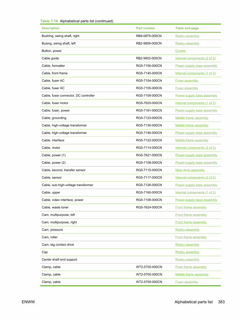
Description Part number Table and page
Bushing, swing shaft, right RB9-0879-000CN Rotary assembly
Busing, swing shaft, left RB2-9809-000CN Rotary assembly
Button, power Covers
Cable guide RB2-9903-000CN Internal components (2 of 2)
Cable, formatter RG5-7156-000CN Power-supply base assembly
Cable, front frame RG5-7145-000CN Internal components (1 of 2)
Cable, fuser AC RG5-7154-000CN Fuser assembly
Cable, fuser AC RG5-7155-000CN Fuser assembly
Cable, fuser connector, DC controller RG5-7109-000CN Power-supply base assembly
Cable, fuser motor RG5-7620-000CN Internal components (1 of 2)
Cable, fuser, power RG5-7161-000CN Power-supply base assembly
Cable, grounding RG5-7123-000CN Middle frame assembly
Cable, high-voltage transformer RG5-7130-000CN Middle frame assembly
Cable, high-voltage transformer RG5-7146-000CN Power-supply base assembly
Cable, interface RG5-7122-000CN Middle frame assembly
Cable, motor RG5-7114-000CN Internal components (2 of 2)
Cable, power (1) RG5-7621-000CN Power-supply base assembly
Cable, power (2) RG5-7108-000CN Power-supply base assembly
Cable, second, transfer sensor RG5-7115-000CN Main drive assembly
Cable, sensor RG5-7117-000CN Internal components (2 of 2)
Cable, sub-high-voltage transformer RG5-7126-000CN Power-supply base assembly
Cable, upper RG5-7160-000CN Internal components (1 of 2)
Cable, video interface, power RG5-7106-000CN Power-supply base assembly
Cable, waste toner RG5-7624-000CN Front frame assembly
Cam, multipurpose, left Front frame assembly
Cam, multipurpose, right Front frame assembly
Cam, pressure Rotary assembly
Cam, roller Front frame assembly
Cam, tag contact drive Rotary assembly
Cap Rotary assembly
Center shaft end support Rotary assembly
Clamp, cable WT2-5700-000CN Front frame assembly
Clamp, cable WT2-5700-000CN Middle frame assembly
Clamp, cable WT2-5700-000CN Fuser assembly
Table 7-19 Alphabetical parts list (continued)
ENWW Alphabetical parts list 383

Description Part number Table and page
Clip, cable WT2-5056-000CN Front frame assembly
Clip, cable WT2-5610-000CN Middle frame assembly
Clip, cable WT2-5737-000CN Power-supply base assembly
Clutch, electromagnetic RH7-5389-000CN Internal components (1 of 2)
Clutch, electromagnetic RH7-5335-000CN Main drive assembly
Control panel, copy (HP Color LaserJet 2820 all-in-one) Q3948-60111CN ADF and scanner assembly
Control panel, fax (HP Color LaserJet 2830 all-in-one andHP Color LaserJet 2840 all-in-one)
Q3949-60134CN ADF and scanner assembly
Control-panel bezel, copy, Arabic Q3948-60164CN ADF and scanner assembly
Control-panel bezel, copy, Czech Q3948-60157CN ADF and scanner assembly
Control-panel bezel, copy, Danish Q3948-60155CN ADF and scanner assembly
Control-panel bezel, copy, Dutch Q3948-60150CN ADF and scanner assembly
Control-panel bezel, copy, English Q3948-60136CN ADF and scanner assembly
Control-panel bezel, copy, Finnish Q3948-60154CN ADF and scanner assembly
Control-panel bezel, copy, French Q3948-60149CN ADF and scanner assembly
Control-panel bezel, copy, German Q3948-60148CN ADF and scanner assembly
Control-panel bezel, copy, Hebrew Q3948-60163CN ADF and scanner assembly
Control-panel bezel, copy, Hungarian Q3948-60158CN ADF and scanner assembly
Control-panel bezel, copy, Italian Q3948-60151CN ADF and scanner assembly
Control-panel bezel, copy, Korean Q3948-60166CN ADF and scanner assembly
Control-panel bezel, copy, Norwegian Q3948-60153CN ADF and scanner assembly
Control-panel bezel, copy, Polish Q3948-60159CN ADF and scanner assembly
Control-panel bezel, copy, Portuguese Q3948-60147CN ADF and scanner assembly
Control-panel bezel, copy, Russian Q3948-60156CN ADF and scanner assembly
Control-panel bezel, copy, simplified Chinese Q3948-60167CN ADF and scanner assembly
Control-panel bezel, copy, Slovak Q3948-60160CN ADF and scanner assembly
Control-panel bezel, copy, Spanish Q3948-60146CN ADF and scanner assembly
Control-panel bezel, copy, Swedish Q3950-60108CN ADF and scanner assembly
Control-panel bezel, copy, Thai Q3948-60168CN ADF and scanner assembly
Control-panel bezel, copy, traditional Chinese Q3948-60165CN ADF and scanner assembly
Control-panel bezel, copy, Turkish Q3948-60161CN ADF and scanner assembly
Control-panel bezel, copy, Vietnamese Q3948-60169CN ADF and scanner assembly
Control-panel bezel, fax, Arabic Q3950-60120CN ADF and scanner assembly
Control-panel bezel, fax, Czech Q3950-60113CN ADF and scanner assembly
Table 7-19 Alphabetical parts list (continued)
384 Chapter 7 Parts and diagrams ENWW

Description Part number Table and page
Control-panel bezel, fax, Danish Q3950-60111CN ADF and scanner assembly
Control-panel bezel, fax, Dutch Q3950-60106CN ADF and scanner assembly
Control-panel bezel, fax, English Q3950-60101CN ADF and scanner assembly
Control-panel bezel, fax, Finnish Q3950-60110CN ADF and scanner assembly
Control-panel bezel, fax, French Q3950-60105CN ADF and scanner assembly
Control-panel bezel, fax, German Q3950-60104CN ADF and scanner assembly
Control-panel bezel, fax, Hebrew Q3950-60119CN ADF and scanner assembly
Control-panel bezel, fax, Hungarian Q3950-60114CN ADF and scanner assembly
Control-panel bezel, fax, Italian Q3950-60107CN ADF and scanner assembly
Control-panel bezel, fax, Korean Q3950-60122CN ADF and scanner assembly
Control-panel bezel, fax, Norwegian Q3950-60109CN ADF and scanner assembly
Control-panel bezel, fax, Polish Q3950-60115CN ADF and scanner assembly
Control-panel bezel, fax, Portuguese Q3950-60103CN ADF and scanner assembly
Control-panel bezel, fax, Russian Q3950-60112CN ADF and scanner assembly
Control-panel bezel, fax, simplified Chinese Q3950-60123CN ADF and scanner assembly
Control-panel bezel, fax, Slovak Q3950-60116CN ADF and scanner assembly
Control-panel bezel, fax, Spanish Q3950-60102CN ADF and scanner assembly
Control-panel bezel, fax, Swedish Q3948-60152CN ADF and scanner assembly
Control-panel bezel, fax, Thai Q3950-60124CN ADF and scanner assembly
Control-panel bezel, fax, traditional Chinese Q3950-60121CN ADF and scanner assembly
Control-panel bezel, fax, Turkish Q3950-60117CN ADF and scanner assembly
Control-panel bezel, fax, Vietnamese Q3950-60125CN ADF and scanner assembly
Coupling, drum Main drive assembly
Coupling, ITB Main drive assembly
Cover, cartridge RF5-4055-000CN Covers
Cover, cartridge Covers
Cover, edge Internal components (2 of 2)
Cover, face-down RB3-1136-000CN Covers
Cover, face-up, lower Fuser assembly
Cover, face-up, upper RB3-1140-000CN Fuser assembly
Cover, front RB3-1125-000CN Covers
Cover, fuser, upper RB3-1032-000CN Fuser assembly
Cover, gear RB3-0052-000CN Middle frame assembly
Cover, I/O RB3-1137-000CN Covers
Table 7-19 Alphabetical parts list (continued)
ENWW Alphabetical parts list 385

Description Part number Table and page
Cover, left RB3-1128-000CN Covers
Cover, left rear RB3-1131-000CN Covers
Cover, left upper RB3-1126-000CN Covers
Cover, memory RB3-1138-000CN Covers
Cover, mount motor Rotary-drive assembly
Cover, MP. gauss blocking RB3-0120-000CN Front frame assembly
Cover, multipurpose Front frame assembly
Cover, multipurpose, lower RB3-1135-000CN Front frame assembly
Cover, multipurpose, roller RB3-0104-000CN Front frame assembly
Cover, multipurpose, upper RB3-1134-000CN Front frame assembly
Cover, pressure motor RB2-9916-000CN Rear frame assembly
Cover, rack RB3-0089-030CN Covers
Cover, rear RB3-1130-000CN Covers
Cover, right Covers
Cover, right rear RB3-1132-000CN Covers
Cover, right side plate Rotary assembly
Cover, top Covers
Cover, top (assembly) RG5-7597-000CN Covers
Cover, vent RB3-1139-000CN Covers
Crossmember, beam Internal components (2 of 2)
Crossmember, power supply base Power-supply base assembly
Crossmember, rotary pressure Rotary assembly
Crossmember, scanner Internal components (2 of 2)
Damper assembly RB2-6248-000CN Front frame assembly
DC Controller PCA RG5-7646-000CN PCA assemblies
Density-sensor PCA RH7-7158-000CN PCA assemblies
Dev. rotary cable RG5-7129-000CN Rotary assembly
Disc, rotary left Rotary assembly
Disc, rotary right Rotary assembly
Drawer connector WS1-6336-000CN Middle frame assembly
Duct, fan RB9-0901-000CN Internal components (1 of 2)
Duct, fuser RB2-9904-000CN Rear frame assembly
E-ring XD2-1100-322CN Internal components (1 of 2)
E-ring Main drive assembly
Table 7-19 Alphabetical parts list (continued)
386 Chapter 7 Parts and diagrams ENWW
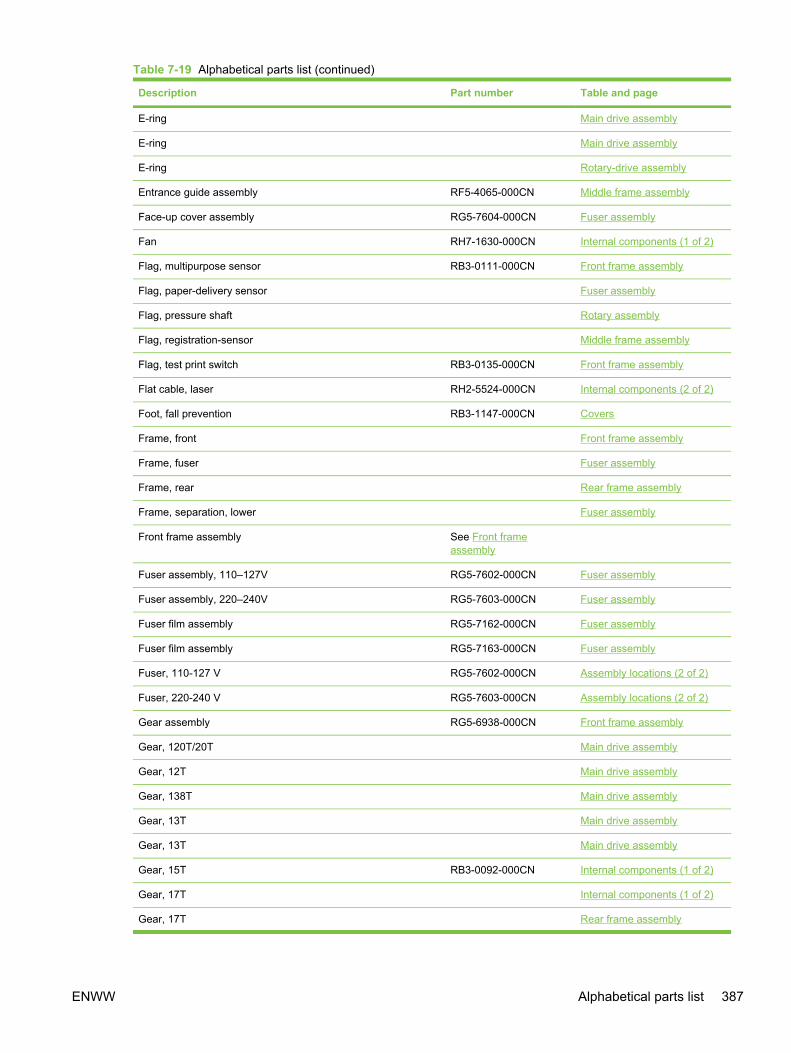
Description Part number Table and page
E-ring Main drive assembly
E-ring Main drive assembly
E-ring Rotary-drive assembly
Entrance guide assembly RF5-4065-000CN Middle frame assembly
Face-up cover assembly RG5-7604-000CN Fuser assembly
Fan RH7-1630-000CN Internal components (1 of 2)
Flag, multipurpose sensor RB3-0111-000CN Front frame assembly
Flag, paper-delivery sensor Fuser assembly
Flag, pressure shaft Rotary assembly
Flag, registration-sensor Middle frame assembly
Flag, test print switch RB3-0135-000CN Front frame assembly
Flat cable, laser RH2-5524-000CN Internal components (2 of 2)
Foot, fall prevention RB3-1147-000CN Covers
Frame, front Front frame assembly
Frame, fuser Fuser assembly
Frame, rear Rear frame assembly
Frame, separation, lower Fuser assembly
Front frame assembly See Front frameassembly
Fuser assembly, 110–127V RG5-7602-000CN Fuser assembly
Fuser assembly, 220–240V RG5-7603-000CN Fuser assembly
Fuser film assembly RG5-7162-000CN Fuser assembly
Fuser film assembly RG5-7163-000CN Fuser assembly
Fuser, 110-127 V RG5-7602-000CN Assembly locations (2 of 2)
Fuser, 220-240 V RG5-7603-000CN Assembly locations (2 of 2)
Gear assembly RG5-6938-000CN Front frame assembly
Gear, 120T/20T Main drive assembly
Gear, 12T Main drive assembly
Gear, 138T Main drive assembly
Gear, 13T Main drive assembly
Gear, 13T Main drive assembly
Gear, 15T RB3-0092-000CN Internal components (1 of 2)
Gear, 17T Internal components (1 of 2)
Gear, 17T Rear frame assembly
Table 7-19 Alphabetical parts list (continued)
ENWW Alphabetical parts list 387

Description Part number Table and page
Gear, 17T Fuser assembly
Gear, 17T/98T Main drive assembly
Gear, 186T RS7-0573-000CN Main drive assembly
Gear, 18T Front frame assembly
Gear, 18T RB3-0091-000CN Internal components (1 of 2)
Gear, 18T Rotary assembly
Gear, 19T Rotary assembly
Gear, 20T/40T RS7-0424-000CN Front frame assembly
Gear, 20T/40T Front frame assembly
Gear, 20T/70T Rotary-drive assembly
Gear, 21T/35T Main drive assembly
Gear, 23T RB3-0022-000CN Middle frame assembly
Gear, 23T/54T RS7-0571-000CN Main drive assembly
Gear, 25T Rotary assembly
Gear, 26T RS7-0418-000CN Front frame assembly
Gear, 26T RS7-0429-000CN Front frame assembly
Gear, 26T/34T Middle frame assembly
Gear, 26T/50T RS7-0426-000CN Front frame assembly
Gear, 27T Rotary assembly
Gear, 28T Rotary assembly
Gear, 28T Rotary assembly
Gear, 28T RS7-0582-000CN Fuser assembly
Gear, 30T RS7-0425-000CN Front frame assembly
Gear, 30T RS7-0428-000CN Middle frame assembly
Gear, 30T RS7-0580-000CN Fuser assembly
Gear, 31T Front frame assembly
Gear, 31T/90T RS7-0572-000CN Main drive assembly
Gear, 32T/123T RS7-0574-000CN Main drive assembly
Gear, 32T/37T RS7-0435-000CN Internal components (1 of 2)
Gear, 34T Internal components (2 of 2)
Gear, 35T Main drive assembly
Gear, 35T Main drive assembly
Gear, 37T/43T RS7-0436-000CN Internal components (1 of 2)
Gear, 48T Rotary-drive assembly
Table 7-19 Alphabetical parts list (continued)
388 Chapter 7 Parts and diagrams ENWW
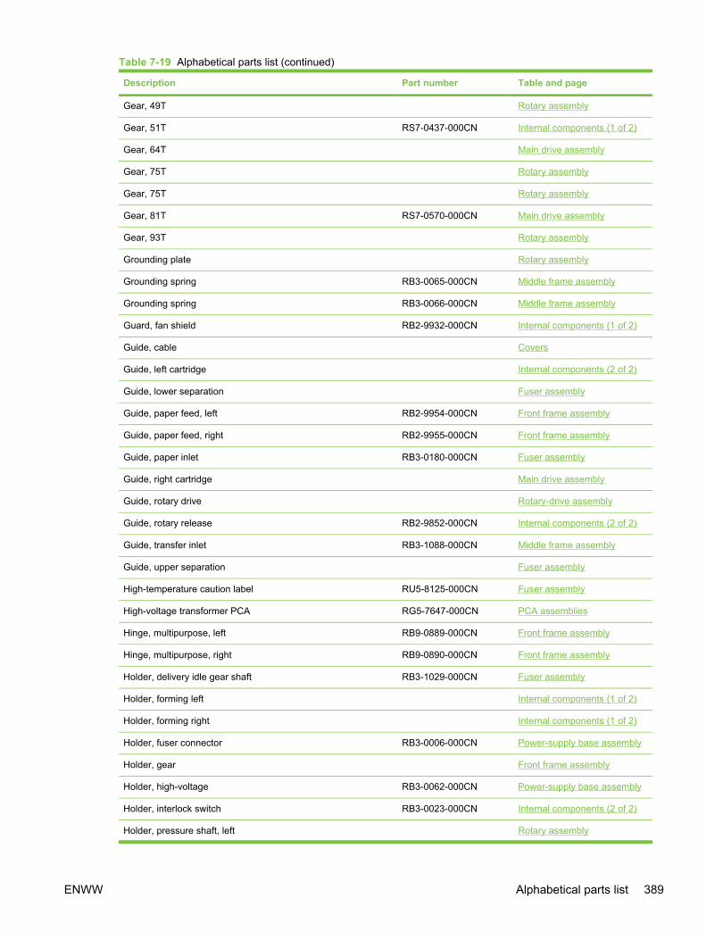
Description Part number Table and page
Gear, 49T Rotary assembly
Gear, 51T RS7-0437-000CN Internal components (1 of 2)
Gear, 64T Main drive assembly
Gear, 75T Rotary assembly
Gear, 75T Rotary assembly
Gear, 81T RS7-0570-000CN Main drive assembly
Gear, 93T Rotary assembly
Grounding plate Rotary assembly
Grounding spring RB3-0065-000CN Middle frame assembly
Grounding spring RB3-0066-000CN Middle frame assembly
Guard, fan shield RB2-9932-000CN Internal components (1 of 2)
Guide, cable Covers
Guide, left cartridge Internal components (2 of 2)
Guide, lower separation Fuser assembly
Guide, paper feed, left RB2-9954-000CN Front frame assembly
Guide, paper feed, right RB2-9955-000CN Front frame assembly
Guide, paper inlet RB3-0180-000CN Fuser assembly
Guide, right cartridge Main drive assembly
Guide, rotary drive Rotary-drive assembly
Guide, rotary release RB2-9852-000CN Internal components (2 of 2)
Guide, transfer inlet RB3-1088-000CN Middle frame assembly
Guide, upper separation Fuser assembly
High-temperature caution label RU5-8125-000CN Fuser assembly
High-voltage transformer PCA RG5-7647-000CN PCA assemblies
Hinge, multipurpose, left RB9-0889-000CN Front frame assembly
Hinge, multipurpose, right RB9-0890-000CN Front frame assembly
Holder, delivery idle gear shaft RB3-1029-000CN Fuser assembly
Holder, forming left Internal components (1 of 2)
Holder, forming right Internal components (1 of 2)
Holder, fuser connector RB3-0006-000CN Power-supply base assembly
Holder, gear Front frame assembly
Holder, high-voltage RB3-0062-000CN Power-supply base assembly
Holder, interlock switch RB3-0023-000CN Internal components (2 of 2)
Holder, pressure shaft, left Rotary assembly
Table 7-19 Alphabetical parts list (continued)
ENWW Alphabetical parts list 389

Description Part number Table and page
Holder, pressure shaft, right Rotary assembly
Holder, separation pad Front frame assembly
Holder, tag Front frame assembly
Holder, tag contact Front frame assembly
Holder, tag contact Rotary assembly
Holder, top sensor PCA Front frame assembly
Holder, transfer sensor RB2-9924-000CN Middle frame assembly
Insulating sheet RB3-1110-000CN Middle frame assembly
Insulating sheet RB3-0007-000CN Power-supply base assembly
Label, CRG Covers
Label, high voltage caution RS6-8668-000CN Internal components (1 of 2)
Label, I/O operation Covers
Label, image cartridge RS6-8687-000CN Front frame assembly
Label, rotary inlet Rotary assembly
Label, rotary inlet Rotary assembly
Label, rotary inlet Rotary assembly
Label, rotary inlet Rotary assembly
Laser/scanner RG5-6890-000CN Internal components (2 of 2)
Left cartridge guide assembly RG5-6935-000CN Internal components (2 of 2)
Left cover assembly RG5-7598-000CN Covers
Left side plate assembly Internal components (2 of 2)
Left support assembly RG5-7632-000CN Internal components (2 of 2)
Lever, lock release, left RB3-0179-000CN Fuser assembly
Lever, lock release, right RB3-0178-000CN Fuser assembly
Lever, pressure-release sensor, left Fuser assembly
Lever, pressure-release sensor, right Fuser assembly
Lever, pressure-release, left RB3-1167-000CN Fuser assembly
Lever, pressure-release, right RB3-1166-000CN Fuser assembly
Link unit, left RG5-7645-000CN Covers
Link unit, right RG5-7630-000CN Covers
Low-voltage PCA, 110-127 V RH3-2260-000CN PCA assemblies
Low-voltage PCA, 220-240 V RH3-2261-000CN PCA assemblies
Lower face-down roller assembly RG5-7595-000CN Rear frame assembly
Main drive assembly RG5-7579-000CN Assembly locations (2 of 2)
Table 7-19 Alphabetical parts list (continued)
390 Chapter 7 Parts and diagrams ENWW
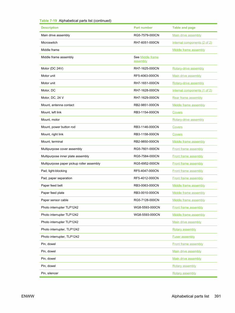
Description Part number Table and page
Main drive assembly RG5-7579-000CN Main drive assembly
Microswitch RH7-6051-000CN Internal components (2 of 2)
Middle frame Middle frame assembly
Middle frame assembly See Middle frameassembly
Motor (DC 24V) RH7-1625-000CN Rotary-drive assembly
Motor unit RF5-4063-000CN Main drive assembly
Motor unit RH7-1651-000CN Rotary-drive assembly
Motor, DC RH7-1628-000CN Internal components (1 of 2)
Motor, DC, 24 V RH7-1629-000CN Rear frame assembly
Mount, antenna contact RB2-9851-000CN Middle frame assembly
Mount, left link RB3-1154-000CN Covers
Mount, motor Rotary-drive assembly
Mount, power button rod RB3-1146-000CN Covers
Mount, right link RB3-1158-000CN Covers
Mount, terminal RB2-9850-000CN Middle frame assembly
Multipurpose cover assembly RG5-7601-000CN Front frame assembly
Multipurpose inner plate assembly RG5-7584-000CN Front frame assembly
Multipurpose paper pickup roller assembly RG5-6952-000CN Front frame assembly
Pad, light-blocking RF5-4047-000CN Front frame assembly
Pad, paper separation RF5-4012-000CN Front frame assembly
Paper feed belt RB3-0063-000CN Middle frame assembly
Paper feed plate RB3-0010-000CN Middle frame assembly
Paper sensor cable RG5-7128-000CN Middle frame assembly
Photo interrupter TLP1242 WG8-5593-000CN Front frame assembly
Photo interrupter TLP1242 WG8-5593-000CN Middle frame assembly
Photo interrupter TLP1242 Main drive assembly
Photo interrupter, TLP1242 Rotary assembly
Photo interrupter, TLP1242 Fuser assembly
Pin, dowel Front frame assembly
Pin, dowel Main drive assembly
Pin, dowel Main drive assembly
Pin, dowel Rotary assembly
Pin, silencer Rotary assembly
Table 7-19 Alphabetical parts list (continued)
ENWW Alphabetical parts list 391

Description Part number Table and page
Pin, support Main drive assembly
Pin, tag Front frame assembly
Plate, formatter grounding Covers
Plate, interlock switch shield Covers
Plate, multipurpose inner Front frame assembly
Plate, photo card crossmember RB2-9976-000CN Internal components (2 of 2)
Plate, photo card mounting Internal components (2 of 2)
Plate, pressure lock Rotary assembly
Plate, rating Internal components (1 of 2)
Plate, silencer pin Rotary assembly
Plate, spring positioning Rotary assembly
Plate, static eliminator Covers
Plate, swing shaft grounding RB3-1113-000CN Internal components (1 of 2)
Plate, tag contact Rotary assembly
Power-supply base assembly See Power-supply baseassembly
Assembly locations (2 of 2)
Pressure plate RB3-1024-000CN Fuser assembly
Pulley RB3-0061-000CN Middle frame assembly
Pulley RB3-0067-000CN Middle frame assembly
Rack RB3-0090-000CN Main drive assembly
Rack, slide, left Front frame assembly
Rack, slide, right Front frame assembly
Rear frame assembly See Covers
Registration front guide Middle frame assembly
Registration holder Middle frame assembly
Registration pressure arm Middle frame assembly
Registration roller Middle frame assembly
Registration roller Middle frame assembly
Registration roller assembly RG5-6939-000CN Middle frame assembly
Registration roller shaft Middle frame assembly
Registration shutter Middle frame assembly
Registration shutter assembly RG5-6940-000CN Middle frame assembly
Registration-sensor PCA RG5-7613-000CN PCA assemblies
Reinforcement plate Rotary assembly
Table 7-19 Alphabetical parts list (continued)
392 Chapter 7 Parts and diagrams ENWW
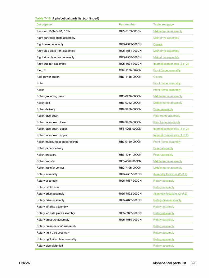
Description Part number Table and page
Resistor, 500MOHM, 0.3W RH5-3169-000CN Middle frame assembly
Right cartridge guide assembly Main drive assembly
Right cover assembly RG5-7599-000CN Covers
Right side plate front assembly RG5-7581-000CN Main drive assembly
Right side plate rear assembly RG5-7580-000CN Main drive assembly
Right support assembly RG5-7631-000CN Internal components (2 of 2)
Ring, E XD2-1100-502CN Front frame assembly
Rod, power button RB3-1145-000CN Covers
Roller Front frame assembly
Roller Front frame assembly
Roller grounding plate RB3-0286-000CN Middle frame assembly
Roller, belt RB3-0012-000CN Middle frame assembly
Roller, delivery RB2-9950-000CN Fuser assembly
Roller, face-down Rear frame assembly
Roller, face-down, lower RB2-9909-000CN Rear frame assembly
Roller, face-down, upper RF5-4068-000CN Internal components (1 of 2)
Roller, face-down, upper Internal components (1 of 2)
Roller, multipurpose paper pickup RB3-0160-000CN Front frame assembly
Roller, paper-delivery Fuser assembly
Roller, pressure RB3-1034-000CN Fuser assembly
Roller, transfer RF5-4067-000CN Middle frame assembly
Roller, transfer sensor RB2-7195-000CN Middle frame assembly
Rotary assembly RG5-7587-000CN Assembly locations (2 of 2)
Rotary assembly RG5-7587-000CN Rotary assembly
Rotary center shaft Rotary assembly
Rotary drive assembly RG5-7592-000CN Assembly locations (2 of 2)
Rotary drive assembly RG5-7842-000CN Rotary-drive assembly
Rotary left disc assembly Rotary assembly
Rotary left side plate assembly RG5-6942-000CN Rotary assembly
Rotary pressure assembly RG5-7589-000CN Rotary assembly
Rotary pressure shaft assembly Rotary assembly
Rotary right disc assembly Rotary assembly
Rotary right side plate assembly Rotary assembly
Rotary side plate, left Rotary assembly
Table 7-19 Alphabetical parts list (continued)
ENWW Alphabetical parts list 393

Description Part number Table and page
Rotary side plate, right Rotary assembly
Rotary swing shaft Rotary assembly
Rubber foot RB2-6297-000CN Middle frame assembly
Scanner crossmember assembly RG5-6907-000CN Internal components (2 of 2)
Scanning assembly Q3948-60191CN ADF and scanner assembly
Screw, B, M3x8 Middle frame assembly
Screw, P, M3x8 XB4-5300-809CN Covers
Screw, RS, M3x10 XA9-1501-000CN Internal components (1 of 2)
Screw, RS, M3X6 Internal components (2 of 2)
Screw, RS, M3X6 Main drive assembly
Screw, RS, M3x6 XA9-1495-000CN Internal components (1 of 2)
Screw, RS, M3x6 XA9-0849-000CN Internal components (2 of 2)
Screw, RS, M3x6 XA9-1495-000CN Internal components (2 of 2)
Screw, RS, M3x6 XA9-0849-000CN Rear frame assembly
Screw, RS, M3x6 Rotary assembly
Screw, RS, M3x6 Rotary-drive assembly
Screw, RS, M3x8 XA9-1291-000CN Covers
Screw, RS, M3x8 XA9-1449-000CN Internal components (1 of 2)
Screw, RS, M3x8 XA9-1449-000CN Power-supply base assembly
Screw, RS, M3x8 XA9-1500-000CN Fuser assembly
Screw, RS, M3x8 XA9-1449-000CN Fuser assembly
Screw, S, M3X8 Main drive assembly
Screw, S, M3x8 XA9-1500-000CN Power-supply base assembly
Screw, tapping, truss head, M4X10 XB4-7401-005CN Covers
Screw, tapping, truss head, M4X10 XB4-7401-005CN Front frame assembly
Screw, tapping, truss head, M4x10 XB4-7401-005CN Internal components (1 of 2)
Screw, tapping, truss head, M4x10 XB4-7401-005CN Rear frame assembly
Screw, tapping, truss head, M4x10 XB4-7401-005CN Middle frame assembly
Screw, TP, M3x4 Rotary assembly
Screw, TP, M3x4 Rotary-drive assembly
Screw, TP, M3X6 Front frame assembly
Screw, w/washer, M3x6 XB2-4300-605CN Middle frame assembly
Screw, w/washer, M3x6 Rotary assembly
Screw, with washer, M4x12 Fuser assembly
Table 7-19 Alphabetical parts list (continued)
394 Chapter 7 Parts and diagrams ENWW

Description Part number Table and page
Sensor flag arm RB2-9925-000CN Middle frame assembly
Separation lower guide assembly RG5-7577-000CN Fuser assembly
Separation upper guide assembly RG5-7576-000CN Fuser assembly
Shaft Front frame assembly
Shaft Front frame assembly
Shaft, feed drive RB3-0011-000CN Middle frame assembly
Shaft, gear Internal components (2 of 2)
Shaft, gear drive Main drive assembly
Shaft, idler gear RB3-0060-000CN Middle frame assembly
Shaft, image drive Main drive assembly
Shaft, lever RB2-4933-000CN Fuser assembly
Shaft, main drive Main drive assembly
Shaft, paper pickup clutch gear Front frame assembly
Shaft, rotary pressure Rotary assembly
Sheet Internal components (2 of 2)
Sheet, discharge Rotary assembly
Sheet, dust-proof Front frame assembly
Sheet, noise-proof rubber Covers
Sheet, protective, A RB3-1379-000CN Internal components (2 of 2)
Sheet, protective, B RB3-1380-000CN Internal components (2 of 2)
Sheet, separation Front frame assembly
Side plate, left Internal components (2 of 2)
Side plate, right front Main drive assembly
Side plate, right rear Main drive assembly
Side plate, right rear Main drive assembly
Sleeve thermistor unit RH7-7159-000CN Internal components (1 of 2)
Solenoid RH7-5383-000CN Front frame assembly
Solenoid RH7-5384-000CN Rotary-drive assembly
Spacer, left RB2-9935-000CN Fuser assembly
Spacer, right RB2-9934-000CN Fuser assembly
Spring Rotary assembly
Spring, compression RS6-2771-000CN Covers
Spring, compression Front frame assembly
Spring, compression Front frame assembly
Table 7-19 Alphabetical parts list (continued)
ENWW Alphabetical parts list 395
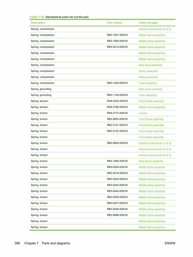
Description Part number Table and page
Spring, compression Internal components (2 of 2)
Spring, compression RB3-1091-000CN Middle frame assembly
Spring, compression RB3-1092-000CN Middle frame assembly
Spring, compression RB3-0015-000CN Middle frame assembly
Spring, compression Middle frame assembly
Spring, compression Middle frame assembly
Spring, compression Main drive assembly
Spring, compression Rotary assembly
Spring, compression Rotary assembly
Spring, compression RB3-1025-000CN Fuser assembly
Spring, grounding Main drive assembly
Spring, grounding RB3-1150-000CN Fuser assembly
Spring, tension RS6-2030-000CN Front frame assembly
Spring, tension RS6-2766-000CN Middle frame assembly
Spring, torsion RS6-2772-000CN Covers
Spring, torsion RB2-9952-000CN Front frame assembly
Spring, torsion RB3-0121-000CN Front frame assembly
Spring, torsion RB3-0122-000CN Front frame assembly
Spring, torsion Front frame assembly
Spring, torsion RB2-9905-000CN Internal components (1 of 2)
Spring, torsion Internal components (2 of 2)
Spring, torsion Internal components (2 of 2)
Spring, torsion RB3-1065-000CN Rear frame assembly
Spring, torsion RB3-0045-000CN Middle frame assembly
Spring, torsion RB3-0016-000CN Middle frame assembly
Spring, torsion RB3-0042-000CN Middle frame assembly
Spring, torsion RB3-0043-000CN Middle frame assembly
Spring, torsion RB3-0044-000CN Middle frame assembly
Spring, torsion RB3-0046-000CN Middle frame assembly
Spring, torsion RB3-0047-000CN Middle frame assembly
Spring, torsion RB3-0048-000CN Middle frame assembly
Spring, torsion RB2-9999-000CN Middle frame assembly
Spring, torsion Middle frame assembly
Spring, torsion Middle frame assembly
Table 7-19 Alphabetical parts list (continued)
396 Chapter 7 Parts and diagrams ENWW

Description Part number Table and page
Spring, torsion Main drive assembly
Spring, torsion Main drive assembly
Spring, torsion Rotary assembly
Spring, torsion Rotary assembly
Spring, torsion Rotary assembly
Spring, torsion Rotary assembly
Spring, torsion Rotary assembly
Spring, torsion Rotary assembly
Spring, torsion Rotary assembly
Spring, torsion Rotary assembly
Spring, torsion Fuser assembly
Spring, torsion Fuser assembly
Spring, torsion Fuser assembly
Static charge eliminator plate RB3-0009-000CN Middle frame assembly
Stopper, A Rotary assembly
Stopper, B Rotary assembly
Sub-high-voltage transformer PCA RG5-7616-000CN PCA assemblies
Support, high-voltage PCA VT2-0012-005CN Power-supply base assembly
Support, spring Main drive assembly
Support, spring Main drive assembly
Support, spring, left Rotary assembly
Support, spring, right Rotary assembly
Support, tag contact Rotary assembly
Support, tag pin Front frame assembly
Tag contact assembly RG5-7132-000CN Rotary assembly
Tag contact PCA RG5-7131-000CN Front frame assembly
Timing belt RB1-8668-030CN Middle frame assembly
Toner-sensor PCA RG5-6964-000CN Rotary assembly
Toner-sensor PCA RG5-7609-000CN PCA assemblies
Top sensor PCA RG5-7612-000CN PCA assemblies
Transfer slide plate RB3-0057-000CN Middle frame assembly
Tray, expansion, 1 Front frame assembly
Tray, expansion, 2 Front frame assembly
Tray, toner RB3-0019-000CN Internal components (1 of 2)
Table 7-19 Alphabetical parts list (continued)
ENWW Alphabetical parts list 397

Description Part number Table and page
Upper face-down roller assembly, RG5-7637-000CN Internal components (1 of 2)
Washer Rotary assembly
Waste-toner sensor PCA RG5-7648-000CN PCA assemblies
Table 7-19 Alphabetical parts list (continued)
398 Chapter 7 Parts and diagrams ENWW

Numerical parts listTable 7-20 Numerical parts list
Part number Description Table and page
Cover, top Covers
Cover, right Covers
Button, power Covers
Cover, cartridge Covers
Sheet, noise-proof rubber Covers
Label, I/O operation Covers
Plate, interlock switch shield Covers
Plate, static eliminator Covers
Guide, cable Covers
Label, CRG Covers
Plate, formatter grounding Covers
Shaft, paper pickup clutch gear Front frame assembly
Shaft Front frame assembly
Shaft Front frame assembly
Tray, expansion, 1 Front frame assembly
Tray, expansion, 2 Front frame assembly
Cover, multipurpose Front frame assembly
Sheet, dust-proof Front frame assembly
Frame, front Front frame assembly
Holder, gear Front frame assembly
Screw, TP, M3X6 Front frame assembly
Gear, 20T/40T Front frame assembly
Gear, 31T Front frame assembly
Spring, compression Front frame assembly
Gear, 18T Front frame assembly
Sheet, separation Front frame assembly
Roller Front frame assembly
Rack, slide, right Front frame assembly
Rack, slide, left Front frame assembly
Plate, multipurpose inner Front frame assembly
Cam, roller Front frame assembly
ENWW Numerical parts list 399

Part number Description Table and page
Roller Front frame assembly
Holder, top sensor PCA Front frame assembly
Cam, multipurpose, right Front frame assembly
Cam, multipurpose, left Front frame assembly
Holder, separation pad Front frame assembly
Spring, torsion Front frame assembly
Holder, tag contact Front frame assembly
Holder, tag Front frame assembly
Support, tag pin Front frame assembly
Pin, tag Front frame assembly
Spring, compression Front frame assembly
Pin, dowel Front frame assembly
Plate, rating Internal components (1 of 2)
Bushing Internal components (1 of 2)
Gear, 17T Internal components (1 of 2)
Holder, forming left Internal components (1 of 2)
Holder, forming right Internal components (1 of 2)
Roller, face-down, upper Internal components (1 of 2)
Crossmember, scanner Internal components (2 of 2)
Arm, shutter Internal components (2 of 2)
Crossmember, beam Internal components (2 of 2)
Spring, compression Internal components (2 of 2)
Left side plate assembly Internal components (2 of 2)
Spring, torsion Internal components (2 of 2)
Spring, torsion Internal components (2 of 2)
Gear, 34T Internal components (2 of 2)
Side plate, left Internal components (2 of 2)
Sheet Internal components (2 of 2)
Screw, RS, M3X6 Internal components (2 of 2)
Guide, left cartridge Internal components (2 of 2)
Shaft, gear Internal components (2 of 2)
Cover, edge Internal components (2 of 2)
Plate, photo card mounting Internal components (2 of 2)
Gear, 17T Rear frame assembly
Table 7-20 Numerical parts list (continued)
400 Chapter 7 Parts and diagrams ENWW

Part number Description Table and page
Roller, face-down Rear frame assembly
Bushing Rear frame assembly
Frame, rear Rear frame assembly
Spring, torsion Middle frame assembly
Bushing Middle frame assembly
Flag, registration-sensor Middle frame assembly
Registration roller Middle frame assembly
Registration holder Middle frame assembly
Registration front guide Middle frame assembly
Registration shutter Middle frame assembly
Registration roller Middle frame assembly
Registration roller shaft Middle frame assembly
Spring, torsion Middle frame assembly
Bushing Middle frame assembly
Spring, compression Middle frame assembly
Registration pressure arm Middle frame assembly
Middle frame Middle frame assembly
Screw, B, M3x8 Middle frame assembly
Spring, compression Middle frame assembly
Gear, 26T/34T Middle frame assembly
Crossmember, power supply base Power-supply base assembly
Coupling, drum Main drive assembly
Coupling, ITB Main drive assembly
Support, spring Main drive assembly
Gear, 35T Main drive assembly
Gear, 35T Main drive assembly
Bushing, gear drive shaft Main drive assembly
Bushing, IS drive shaft Main drive assembly
Pin, support Main drive assembly
E-ring Main drive assembly
Gear, 13T Main drive assembly
Gear, 13T Main drive assembly
Gear, 12T Main drive assembly
Gear, 21T/35T Main drive assembly
Table 7-20 Numerical parts list (continued)
ENWW Numerical parts list 401

Part number Description Table and page
Support, spring Main drive assembly
Spring, compression Main drive assembly
Gear, 138T Main drive assembly
Spring, grounding Main drive assembly
Gear, 17T/98T Main drive assembly
Gear, 120T/20T Main drive assembly
Side plate, right rear Main drive assembly
Photo interrupter TLP1242 Main drive assembly
Screw, S, M3X8 Main drive assembly
Gear, 64T Main drive assembly
Screw, RS, M3X6 Main drive assembly
Side plate, right front Main drive assembly
E-ring Main drive assembly
E-ring Main drive assembly
Pin, dowel Main drive assembly
Pin, dowel Main drive assembly
Spring, torsion Main drive assembly
Spring, torsion Main drive assembly
Guide, right cartridge Main drive assembly
Right cartridge guide assembly Main drive assembly
Side plate, right rear Main drive assembly
Shaft, main drive Main drive assembly
Shaft, image drive Main drive assembly
Shaft, gear drive Main drive assembly
Rotary center shaft Rotary assembly
Rotary swing shaft Rotary assembly
Reinforcement plate Rotary assembly
Gear, 75T Rotary assembly
Center shaft end support Rotary assembly
Stopper, A Rotary assembly
Gear, 28T Rotary assembly
Gear, 49T Rotary assembly
Gear, 28T Rotary assembly
Gear, 18T Rotary assembly
Table 7-20 Numerical parts list (continued)
402 Chapter 7 Parts and diagrams ENWW

Part number Description Table and page
Screw, RS, M3x6 Rotary assembly
Spring, torsion Rotary assembly
Spring, torsion Rotary assembly
Pin, dowel Rotary assembly
Cover, right side plate Rotary assembly
Bushing, center shaft, right Rotary assembly
Grounding plate Rotary assembly
Rotary side plate, right Rotary assembly
Gear, 93T Rotary assembly
Gear, 75T Rotary assembly
Gear, 27T Rotary assembly
Ball bearing Rotary assembly
Cap Rotary assembly
Rotary side plate, left Rotary assembly
Bushing, center shaft, left Rotary assembly
Spring, torsion Rotary assembly
Plate, spring positioning Rotary assembly
Spring, torsion Rotary assembly
Crossmember, rotary pressure Rotary assembly
Support, spring, right Rotary assembly
Support, spring, left Rotary assembly
Flag, pressure shaft Rotary assembly
Holder, pressure shaft, right Rotary assembly
Holder, pressure shaft, left Rotary assembly
Holder, tag contact Rotary assembly
Support, tag contact Rotary assembly
Plate, tag contact Rotary assembly
Spring, torsion Rotary assembly
Plate, pressure lock Rotary assembly
Spring, compression Rotary assembly
Spring, compression Rotary assembly
Gear, 25T Rotary assembly
Washer Rotary assembly
Cam, pressure Rotary assembly
Table 7-20 Numerical parts list (continued)
ENWW Numerical parts list 403

Part number Description Table and page
Cam, tag contact drive Rotary assembly
Spring, torsion Rotary assembly
Shaft, rotary pressure Rotary assembly
Disc, rotary right Rotary assembly
Spring, torsion Rotary assembly
Label, rotary inlet Rotary assembly
Label, rotary inlet Rotary assembly
Label, rotary inlet Rotary assembly
Label, rotary inlet Rotary assembly
Disc, rotary left Rotary assembly
Spring, torsion Rotary assembly
Rotary right side plate assembly Rotary assembly
Rotary right disc assembly Rotary assembly
Rotary left disc assembly Rotary assembly
Screw, w/washer, M3x6 Rotary assembly
Rotary pressure shaft assembly Rotary assembly
Stopper, B Rotary assembly
Photo interrupter, TLP1242 Rotary assembly
Pin, silencer Rotary assembly
Sheet, discharge Rotary assembly
Spring Rotary assembly
Screw, TP, M3x4 Rotary assembly
Gear, 19T Rotary assembly
Plate, silencer pin Rotary assembly
Guide, rotary drive Rotary-drive assembly
Cover, mount motor Rotary-drive assembly
Mount, motor Rotary-drive assembly
Gear, 20T/70T Rotary-drive assembly
Gear, 48T Rotary-drive assembly
Screw, TP, M3x4 Rotary-drive assembly
E-ring Rotary-drive assembly
Screw, RS, M3x6 Rotary-drive assembly
Frame, fuser Fuser assembly
Spring, torsion Fuser assembly
Table 7-20 Numerical parts list (continued)
404 Chapter 7 Parts and diagrams ENWW

Part number Description Table and page
Cover, face-up, lower Fuser assembly
Guide, upper separation Fuser assembly
Guide, lower separation Fuser assembly
Flag, paper-delivery sensor Fuser assembly
Spring, torsion Fuser assembly
Bushing Fuser assembly
Roller, paper-delivery Fuser assembly
Spring, torsion Fuser assembly
Lever, pressure-release sensor, right Fuser assembly
Gear, 17T Fuser assembly
Lever, pressure-release sensor, left Fuser assembly
Photo interrupter, TLP1242 Fuser assembly
Frame, separation, lower Fuser assembly
Screw, with washer, M4x12 Fuser assembly
C7296-00014CN ADF scanning window ADF and scanner assembly
C7309-40013CN ADF input-tray flag ADF and scanner assembly
C7309-40153CN ADF cleanout part ADF and scanner assembly
C7309-80013CN ADF input-tray spring ADF and scanner assembly
Q1636-40037CN ADF scanning window frame ADF and scanner assembly
Q2665-60125CN ADF separation pad ADF and scanner assembly
Q3948-40007CN ADF cover ADF and scanner assembly
Q3948-60111CN Control panel, copy (HP Color LaserJet 2820 all-in-one) ADF and scanner assembly
Q3948-60136CN Control-panel bezel, copy, English ADF and scanner assembly
Q3948-60140CN ADF pickup roller ADF and scanner assembly
Q3948-60145CN ADF input tray ADF and scanner assembly
Q3948-60146CN Control-panel bezel, copy, Spanish ADF and scanner assembly
Q3948-60147CN Control-panel bezel, copy, Portuguese ADF and scanner assembly
Q3948-60148CN Control-panel bezel, copy, German ADF and scanner assembly
Q3948-60149CN Control-panel bezel, copy, French ADF and scanner assembly
Q3948-60150CN Control-panel bezel, copy, Dutch ADF and scanner assembly
Q3948-60151CN Control-panel bezel, copy, Italian ADF and scanner assembly
Q3948-60152CN Control-panel bezel, fax, Swedish ADF and scanner assembly
Q3948-60153CN Control-panel bezel, copy, Norwegian ADF and scanner assembly
Q3948-60154CN Control-panel bezel, copy, Finnish ADF and scanner assembly
Table 7-20 Numerical parts list (continued)
ENWW Numerical parts list 405

Part number Description Table and page
Q3948-60155CN Control-panel bezel, copy, Danish ADF and scanner assembly
Q3948-60156CN Control-panel bezel, copy, Russian ADF and scanner assembly
Q3948-60157CN Control-panel bezel, copy, Czech ADF and scanner assembly
Q3948-60158CN Control-panel bezel, copy, Hungarian ADF and scanner assembly
Q3948-60159CN Control-panel bezel, copy, Polish ADF and scanner assembly
Q3948-60160CN Control-panel bezel, copy, Slovak ADF and scanner assembly
Q3948-60161CN Control-panel bezel, copy, Turkish ADF and scanner assembly
Q3948-60163CN Control-panel bezel, copy, Hebrew ADF and scanner assembly
Q3948-60164CN Control-panel bezel, copy, Arabic ADF and scanner assembly
Q3948-60165CN Control-panel bezel, copy, traditional Chinese ADF and scanner assembly
Q3948-60166CN Control-panel bezel, copy, Korean ADF and scanner assembly
Q3948-60167CN Control-panel bezel, copy, simplified Chinese ADF and scanner assembly
Q3948-60168CN Control-panel bezel, copy, Thai ADF and scanner assembly
Q3948-60169CN Control-panel bezel, copy, Vietnamese ADF and scanner assembly
Q3948-60189CN ADF assembly ADF and scanner assembly
Q3948-60191CN Scanning assembly ADF and scanner assembly
Q3949-60134CN Control panel, fax (HP Color LaserJet 2830 all-in-one andHP Color LaserJet 2840 all-in-one)
ADF and scanner assembly
Q3950-60101CN Control-panel bezel, fax, English ADF and scanner assembly
Q3950-60102CN Control-panel bezel, fax, Spanish ADF and scanner assembly
Q3950-60103CN Control-panel bezel, fax, Portuguese ADF and scanner assembly
Q3950-60104CN Control-panel bezel, fax, German ADF and scanner assembly
Q3950-60105CN Control-panel bezel, fax, French ADF and scanner assembly
Q3950-60106CN Control-panel bezel, fax, Dutch ADF and scanner assembly
Q3950-60107CN Control-panel bezel, fax, Italian ADF and scanner assembly
Q3950-60108CN Control-panel bezel, copy, Swedish ADF and scanner assembly
Q3950-60109CN Control-panel bezel, fax, Norwegian ADF and scanner assembly
Q3950-60110CN Control-panel bezel, fax, Finnish ADF and scanner assembly
Q3950-60111CN Control-panel bezel, fax, Danish ADF and scanner assembly
Q3950-60112CN Control-panel bezel, fax, Russian ADF and scanner assembly
Q3950-60113CN Control-panel bezel, fax, Czech ADF and scanner assembly
Q3950-60114CN Control-panel bezel, fax, Hungarian ADF and scanner assembly
Q3950-60115CN Control-panel bezel, fax, Polish ADF and scanner assembly
Q3950-60116CN Control-panel bezel, fax, Slovak ADF and scanner assembly
Table 7-20 Numerical parts list (continued)
406 Chapter 7 Parts and diagrams ENWW
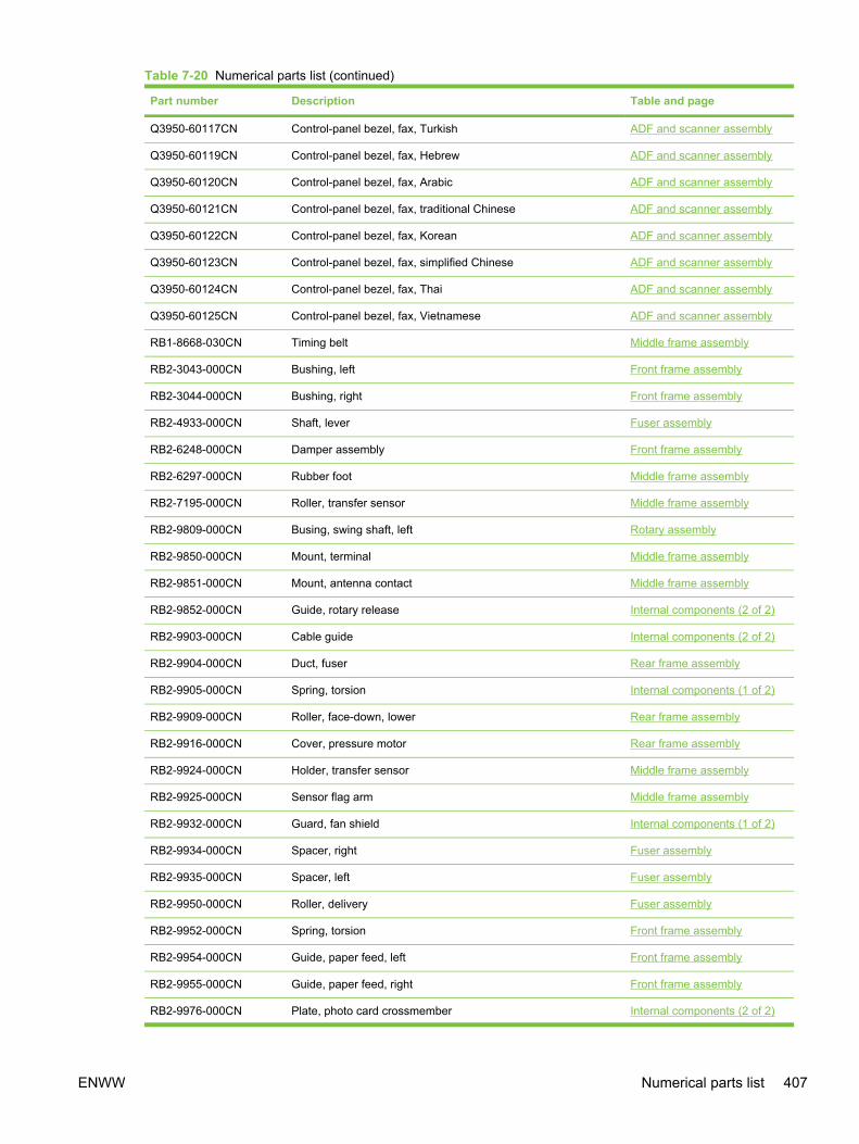
Part number Description Table and page
Q3950-60117CN Control-panel bezel, fax, Turkish ADF and scanner assembly
Q3950-60119CN Control-panel bezel, fax, Hebrew ADF and scanner assembly
Q3950-60120CN Control-panel bezel, fax, Arabic ADF and scanner assembly
Q3950-60121CN Control-panel bezel, fax, traditional Chinese ADF and scanner assembly
Q3950-60122CN Control-panel bezel, fax, Korean ADF and scanner assembly
Q3950-60123CN Control-panel bezel, fax, simplified Chinese ADF and scanner assembly
Q3950-60124CN Control-panel bezel, fax, Thai ADF and scanner assembly
Q3950-60125CN Control-panel bezel, fax, Vietnamese ADF and scanner assembly
RB1-8668-030CN Timing belt Middle frame assembly
RB2-3043-000CN Bushing, left Front frame assembly
RB2-3044-000CN Bushing, right Front frame assembly
RB2-4933-000CN Shaft, lever Fuser assembly
RB2-6248-000CN Damper assembly Front frame assembly
RB2-6297-000CN Rubber foot Middle frame assembly
RB2-7195-000CN Roller, transfer sensor Middle frame assembly
RB2-9809-000CN Busing, swing shaft, left Rotary assembly
RB2-9850-000CN Mount, terminal Middle frame assembly
RB2-9851-000CN Mount, antenna contact Middle frame assembly
RB2-9852-000CN Guide, rotary release Internal components (2 of 2)
RB2-9903-000CN Cable guide Internal components (2 of 2)
RB2-9904-000CN Duct, fuser Rear frame assembly
RB2-9905-000CN Spring, torsion Internal components (1 of 2)
RB2-9909-000CN Roller, face-down, lower Rear frame assembly
RB2-9916-000CN Cover, pressure motor Rear frame assembly
RB2-9924-000CN Holder, transfer sensor Middle frame assembly
RB2-9925-000CN Sensor flag arm Middle frame assembly
RB2-9932-000CN Guard, fan shield Internal components (1 of 2)
RB2-9934-000CN Spacer, right Fuser assembly
RB2-9935-000CN Spacer, left Fuser assembly
RB2-9950-000CN Roller, delivery Fuser assembly
RB2-9952-000CN Spring, torsion Front frame assembly
RB2-9954-000CN Guide, paper feed, left Front frame assembly
RB2-9955-000CN Guide, paper feed, right Front frame assembly
RB2-9976-000CN Plate, photo card crossmember Internal components (2 of 2)
Table 7-20 Numerical parts list (continued)
ENWW Numerical parts list 407
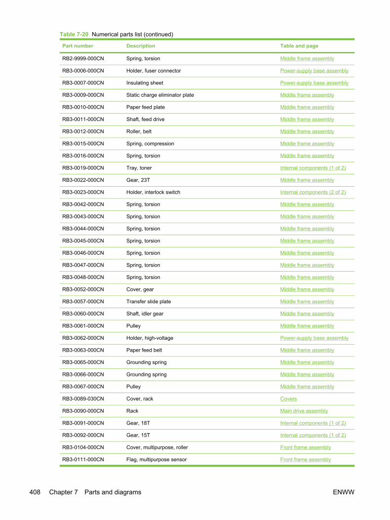
Part number Description Table and page
RB2-9999-000CN Spring, torsion Middle frame assembly
RB3-0006-000CN Holder, fuser connector Power-supply base assembly
RB3-0007-000CN Insulating sheet Power-supply base assembly
RB3-0009-000CN Static charge eliminator plate Middle frame assembly
RB3-0010-000CN Paper feed plate Middle frame assembly
RB3-0011-000CN Shaft, feed drive Middle frame assembly
RB3-0012-000CN Roller, belt Middle frame assembly
RB3-0015-000CN Spring, compression Middle frame assembly
RB3-0016-000CN Spring, torsion Middle frame assembly
RB3-0019-000CN Tray, toner Internal components (1 of 2)
RB3-0022-000CN Gear, 23T Middle frame assembly
RB3-0023-000CN Holder, interlock switch Internal components (2 of 2)
RB3-0042-000CN Spring, torsion Middle frame assembly
RB3-0043-000CN Spring, torsion Middle frame assembly
RB3-0044-000CN Spring, torsion Middle frame assembly
RB3-0045-000CN Spring, torsion Middle frame assembly
RB3-0046-000CN Spring, torsion Middle frame assembly
RB3-0047-000CN Spring, torsion Middle frame assembly
RB3-0048-000CN Spring, torsion Middle frame assembly
RB3-0052-000CN Cover, gear Middle frame assembly
RB3-0057-000CN Transfer slide plate Middle frame assembly
RB3-0060-000CN Shaft, idler gear Middle frame assembly
RB3-0061-000CN Pulley Middle frame assembly
RB3-0062-000CN Holder, high-voltage Power-supply base assembly
RB3-0063-000CN Paper feed belt Middle frame assembly
RB3-0065-000CN Grounding spring Middle frame assembly
RB3-0066-000CN Grounding spring Middle frame assembly
RB3-0067-000CN Pulley Middle frame assembly
RB3-0089-030CN Cover, rack Covers
RB3-0090-000CN Rack Main drive assembly
RB3-0091-000CN Gear, 18T Internal components (1 of 2)
RB3-0092-000CN Gear, 15T Internal components (1 of 2)
RB3-0104-000CN Cover, multipurpose, roller Front frame assembly
RB3-0111-000CN Flag, multipurpose sensor Front frame assembly
Table 7-20 Numerical parts list (continued)
408 Chapter 7 Parts and diagrams ENWW
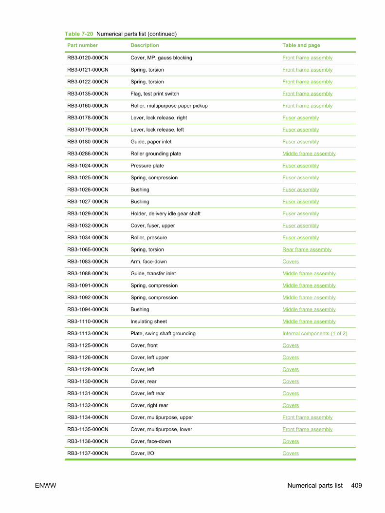
Part number Description Table and page
RB3-0120-000CN Cover, MP. gauss blocking Front frame assembly
RB3-0121-000CN Spring, torsion Front frame assembly
RB3-0122-000CN Spring, torsion Front frame assembly
RB3-0135-000CN Flag, test print switch Front frame assembly
RB3-0160-000CN Roller, multipurpose paper pickup Front frame assembly
RB3-0178-000CN Lever, lock release, right Fuser assembly
RB3-0179-000CN Lever, lock release, left Fuser assembly
RB3-0180-000CN Guide, paper inlet Fuser assembly
RB3-0286-000CN Roller grounding plate Middle frame assembly
RB3-1024-000CN Pressure plate Fuser assembly
RB3-1025-000CN Spring, compression Fuser assembly
RB3-1026-000CN Bushing Fuser assembly
RB3-1027-000CN Bushing Fuser assembly
RB3-1029-000CN Holder, delivery idle gear shaft Fuser assembly
RB3-1032-000CN Cover, fuser, upper Fuser assembly
RB3-1034-000CN Roller, pressure Fuser assembly
RB3-1065-000CN Spring, torsion Rear frame assembly
RB3-1083-000CN Arm, face-down Covers
RB3-1088-000CN Guide, transfer inlet Middle frame assembly
RB3-1091-000CN Spring, compression Middle frame assembly
RB3-1092-000CN Spring, compression Middle frame assembly
RB3-1094-000CN Bushing Middle frame assembly
RB3-1110-000CN Insulating sheet Middle frame assembly
RB3-1113-000CN Plate, swing shaft grounding Internal components (1 of 2)
RB3-1125-000CN Cover, front Covers
RB3-1126-000CN Cover, left upper Covers
RB3-1128-000CN Cover, left Covers
RB3-1130-000CN Cover, rear Covers
RB3-1131-000CN Cover, left rear Covers
RB3-1132-000CN Cover, right rear Covers
RB3-1134-000CN Cover, multipurpose, upper Front frame assembly
RB3-1135-000CN Cover, multipurpose, lower Front frame assembly
RB3-1136-000CN Cover, face-down Covers
RB3-1137-000CN Cover, I/O Covers
Table 7-20 Numerical parts list (continued)
ENWW Numerical parts list 409

Part number Description Table and page
RB3-1138-000CN Cover, memory Covers
RB3-1139-000CN Cover, vent Covers
RB3-1140-000CN Cover, face-up, upper Fuser assembly
RB3-1145-000CN Rod, power button Covers
RB3-1146-000CN Mount, power button rod Covers
RB3-1147-000CN Foot, fall prevention Covers
RB3-1150-000CN Spring, grounding Fuser assembly
RB3-1154-000CN Mount, left link Covers
RB3-1158-000CN Mount, right link Covers
RB3-1166-000CN Lever, pressure-release, right Fuser assembly
RB3-1167-000CN Lever, pressure-release, left Fuser assembly
RB3-1379-000CN Sheet, protective, A Internal components (2 of 2)
RB3-1380-000CN Sheet, protective, B Internal components (2 of 2)
RB9-0879-000CN Bushing, swing shaft, right Rotary assembly
RB9-0889-000CN Hinge, multipurpose, left Front frame assembly
RB9-0890-000CN Hinge, multipurpose, right Front frame assembly
RB9-0901-000CN Duct, fan Internal components (1 of 2)
RF5-4012-000CN Pad, paper separation Front frame assembly
RF5-4047-000CN Pad, light-blocking Front frame assembly
RF5-4055-000CN Cover, cartridge Covers
RF5-4060-000CN Base plate, fixing Fuser assembly
RF5-4063-000CN Motor unit Main drive assembly
RF5-4065-000CN Entrance guide assembly Middle frame assembly
RF5-4067-000CN Roller, transfer Middle frame assembly
RF5-4068-000CN Roller, face-down, upper Internal components (1 of 2)
RG5-6890-000CN Laser/scanner Internal components (2 of 2)
RG5-6907-000CN Scanner crossmember assembly Internal components (2 of 2)
RG5-6935-000CN Left cartridge guide assembly Internal components (2 of 2)
RG5-6938-000CN Gear assembly Front frame assembly
RG5-6939-000CN Registration roller assembly Middle frame assembly
RG5-6940-000CN Registration shutter assembly Middle frame assembly
RG5-6942-000CN Rotary left side plate assembly Rotary assembly
RG5-6952-000CN Multipurpose paper pickup roller assembly Front frame assembly
RG5-6964-000CN Toner-sensor PCA Rotary assembly
Table 7-20 Numerical parts list (continued)
410 Chapter 7 Parts and diagrams ENWW
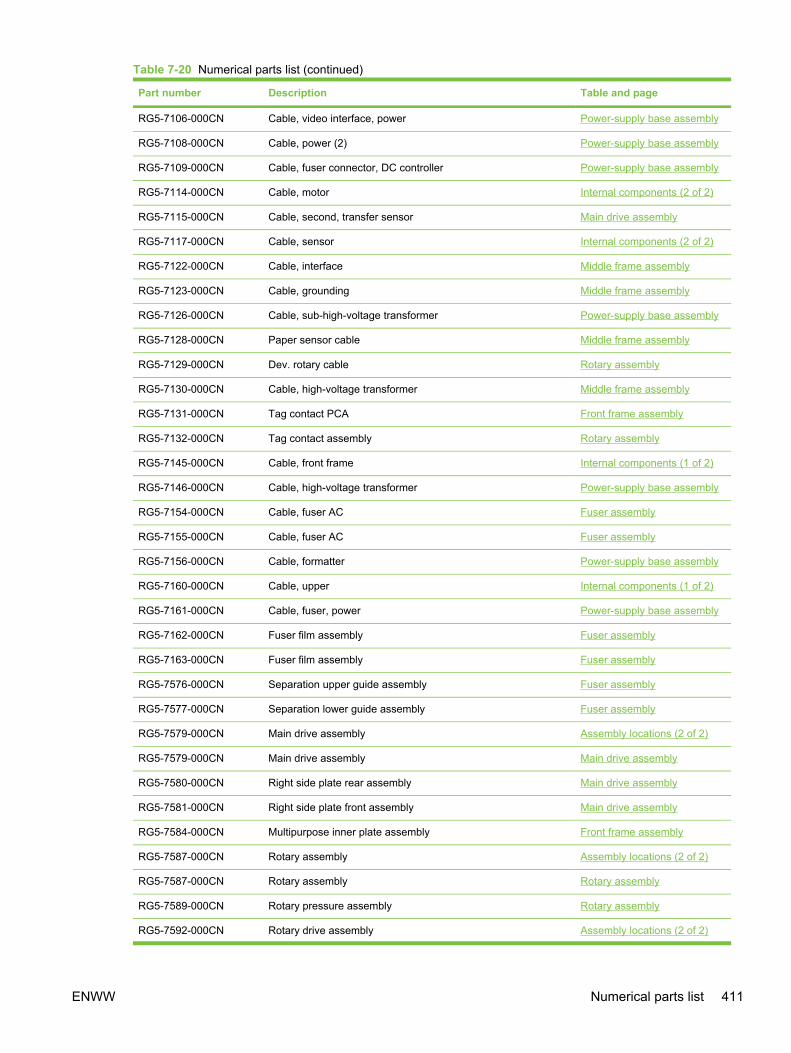
Part number Description Table and page
RG5-7106-000CN Cable, video interface, power Power-supply base assembly
RG5-7108-000CN Cable, power (2) Power-supply base assembly
RG5-7109-000CN Cable, fuser connector, DC controller Power-supply base assembly
RG5-7114-000CN Cable, motor Internal components (2 of 2)
RG5-7115-000CN Cable, second, transfer sensor Main drive assembly
RG5-7117-000CN Cable, sensor Internal components (2 of 2)
RG5-7122-000CN Cable, interface Middle frame assembly
RG5-7123-000CN Cable, grounding Middle frame assembly
RG5-7126-000CN Cable, sub-high-voltage transformer Power-supply base assembly
RG5-7128-000CN Paper sensor cable Middle frame assembly
RG5-7129-000CN Dev. rotary cable Rotary assembly
RG5-7130-000CN Cable, high-voltage transformer Middle frame assembly
RG5-7131-000CN Tag contact PCA Front frame assembly
RG5-7132-000CN Tag contact assembly Rotary assembly
RG5-7145-000CN Cable, front frame Internal components (1 of 2)
RG5-7146-000CN Cable, high-voltage transformer Power-supply base assembly
RG5-7154-000CN Cable, fuser AC Fuser assembly
RG5-7155-000CN Cable, fuser AC Fuser assembly
RG5-7156-000CN Cable, formatter Power-supply base assembly
RG5-7160-000CN Cable, upper Internal components (1 of 2)
RG5-7161-000CN Cable, fuser, power Power-supply base assembly
RG5-7162-000CN Fuser film assembly Fuser assembly
RG5-7163-000CN Fuser film assembly Fuser assembly
RG5-7576-000CN Separation upper guide assembly Fuser assembly
RG5-7577-000CN Separation lower guide assembly Fuser assembly
RG5-7579-000CN Main drive assembly Assembly locations (2 of 2)
RG5-7579-000CN Main drive assembly Main drive assembly
RG5-7580-000CN Right side plate rear assembly Main drive assembly
RG5-7581-000CN Right side plate front assembly Main drive assembly
RG5-7584-000CN Multipurpose inner plate assembly Front frame assembly
RG5-7587-000CN Rotary assembly Assembly locations (2 of 2)
RG5-7587-000CN Rotary assembly Rotary assembly
RG5-7589-000CN Rotary pressure assembly Rotary assembly
RG5-7592-000CN Rotary drive assembly Assembly locations (2 of 2)
Table 7-20 Numerical parts list (continued)
ENWW Numerical parts list 411
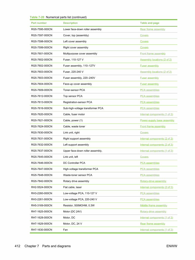
Part number Description Table and page
RG5-7595-000CN Lower face-down roller assembly Rear frame assembly
RG5-7597-000CN Cover, top (assembly) Covers
RG5-7598-000CN Left cover assembly Covers
RG5-7599-000CN Right cover assembly Covers
RG5-7601-000CN Multipurpose cover assembly Front frame assembly
RG5-7602-000CN Fuser, 110-127 V Assembly locations (2 of 2)
RG5-7602-000CN Fuser assembly, 110–127V Fuser assembly
RG5-7603-000CN Fuser, 220-240 V Assembly locations (2 of 2)
RG5-7603-000CN Fuser assembly, 220–240V Fuser assembly
RG5-7604-000CN Face-up cover assembly Fuser assembly
RG5-7609-000CN Toner-sensor PCA PCA assemblies
RG5-7612-000CN Top sensor PCA PCA assemblies
RG5-7613-000CN Registration-sensor PCA PCA assemblies
RG5-7616-000CN Sub-high-voltage transformer PCA PCA assemblies
RG5-7620-000CN Cable, fuser motor Internal components (1 of 2)
RG5-7621-000CN Cable, power (1) Power-supply base assembly
RG5-7624-000CN Cable, waste toner Front frame assembly
RG5-7630-000CN Link unit, right Covers
RG5-7631-000CN Right support assembly Internal components (2 of 2)
RG5-7632-000CN Left support assembly Internal components (2 of 2)
RG5-7637-000CN Upper face-down roller assembly, Internal components (1 of 2)
RG5-7645-000CN Link unit, left Covers
RG5-7646-000CN DC Controller PCA PCA assemblies
RG5-7647-000CN High-voltage transformer PCA PCA assemblies
RG5-7648-000CN Waste-toner sensor PCA PCA assemblies
RG5-7842-000CN Rotary drive assembly Rotary-drive assembly
RH2-5524-000CN Flat cable, laser Internal components (2 of 2)
RH3-2260-000CN Low-voltage PCA, 110-127 V PCA assemblies
RH3-2261-000CN Low-voltage PCA, 220-240 V PCA assemblies
RH5-3169-000CN Resistor, 500MOHM, 0.3W Middle frame assembly
RH7-1625-000CN Motor (DC 24V) Rotary-drive assembly
RH7-1628-000CN Motor, DC Internal components (1 of 2)
RH7-1629-000CN Motor, DC, 24 V Rear frame assembly
RH7-1630-000CN Fan Internal components (1 of 2)
Table 7-20 Numerical parts list (continued)
412 Chapter 7 Parts and diagrams ENWW

Part number Description Table and page
RH7-1651-000CN Motor unit Rotary-drive assembly
RH7-5335-000CN Clutch, electromagnetic Main drive assembly
RH7-5383-000CN Solenoid Front frame assembly
RH7-5384-000CN Solenoid Rotary-drive assembly
RH7-5389-000CN Clutch, electromagnetic Internal components (1 of 2)
RH7-6051-000CN Microswitch Internal components (2 of 2)
RH7-7158-000CN Density-sensor PCA PCA assemblies
RH7-7159-000CN Sleeve thermistor unit Internal components (1 of 2)
RS5-1635-000CN Bushing Front frame assembly
RS5-1637-000CN Bushing Middle frame assembly
RS5-1638-000CN Bushing Front frame assembly
RS6-2030-000CN Spring, tension Front frame assembly
RS6-2766-000CN Spring, tension Middle frame assembly
RS6-2771-000CN Spring, compression Covers
RS6-2772-000CN Spring, torsion Covers
RS6-8668-000CN Label, high voltage caution Internal components (1 of 2)
RS6-8687-000CN Label, image cartridge Front frame assembly
RS7-0418-000CN Gear, 26T Front frame assembly
RS7-0424-000CN Gear, 20T/40T Front frame assembly
RS7-0425-000CN Gear, 30T Front frame assembly
RS7-0426-000CN Gear, 26T/50T Front frame assembly
RS7-0428-000CN Gear, 30T Middle frame assembly
RS7-0429-000CN Gear, 26T Front frame assembly
RS7-0435-000CN Gear, 32T/37T Internal components (1 of 2)
RS7-0436-000CN Gear, 37T/43T Internal components (1 of 2)
RS7-0437-000CN Gear, 51T Internal components (1 of 2)
RS7-0570-000CN Gear, 81T Main drive assembly
RS7-0571-000CN Gear, 23T/54T Main drive assembly
RS7-0572-000CN Gear, 31T/90T Main drive assembly
RS7-0573-000CN Gear, 186T Main drive assembly
RS7-0574-000CN Gear, 32T/123T Main drive assembly
RS7-0580-000CN Gear, 30T Fuser assembly
RS7-0582-000CN Gear, 28T Fuser assembly
RU5-8125-000CN High-temperature caution label Fuser assembly
Table 7-20 Numerical parts list (continued)
ENWW Numerical parts list 413
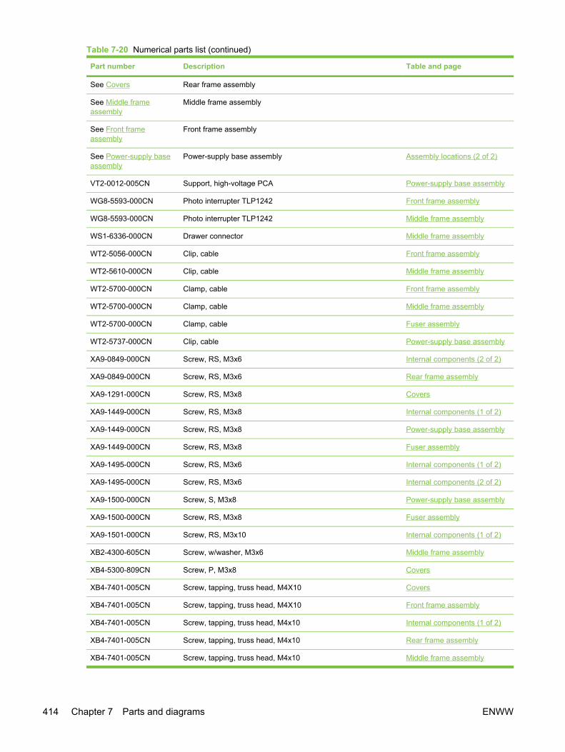
Part number Description Table and page
See Covers Rear frame assembly
See Middle frameassembly
Middle frame assembly
See Front frameassembly
Front frame assembly
See Power-supply baseassembly
Power-supply base assembly Assembly locations (2 of 2)
VT2-0012-005CN Support, high-voltage PCA Power-supply base assembly
WG8-5593-000CN Photo interrupter TLP1242 Front frame assembly
WG8-5593-000CN Photo interrupter TLP1242 Middle frame assembly
WS1-6336-000CN Drawer connector Middle frame assembly
WT2-5056-000CN Clip, cable Front frame assembly
WT2-5610-000CN Clip, cable Middle frame assembly
WT2-5700-000CN Clamp, cable Front frame assembly
WT2-5700-000CN Clamp, cable Middle frame assembly
WT2-5700-000CN Clamp, cable Fuser assembly
WT2-5737-000CN Clip, cable Power-supply base assembly
XA9-0849-000CN Screw, RS, M3x6 Internal components (2 of 2)
XA9-0849-000CN Screw, RS, M3x6 Rear frame assembly
XA9-1291-000CN Screw, RS, M3x8 Covers
XA9-1449-000CN Screw, RS, M3x8 Internal components (1 of 2)
XA9-1449-000CN Screw, RS, M3x8 Power-supply base assembly
XA9-1449-000CN Screw, RS, M3x8 Fuser assembly
XA9-1495-000CN Screw, RS, M3x6 Internal components (1 of 2)
XA9-1495-000CN Screw, RS, M3x6 Internal components (2 of 2)
XA9-1500-000CN Screw, S, M3x8 Power-supply base assembly
XA9-1500-000CN Screw, RS, M3x8 Fuser assembly
XA9-1501-000CN Screw, RS, M3x10 Internal components (1 of 2)
XB2-4300-605CN Screw, w/washer, M3x6 Middle frame assembly
XB4-5300-809CN Screw, P, M3x8 Covers
XB4-7401-005CN Screw, tapping, truss head, M4X10 Covers
XB4-7401-005CN Screw, tapping, truss head, M4X10 Front frame assembly
XB4-7401-005CN Screw, tapping, truss head, M4x10 Internal components (1 of 2)
XB4-7401-005CN Screw, tapping, truss head, M4x10 Rear frame assembly
XB4-7401-005CN Screw, tapping, truss head, M4x10 Middle frame assembly
Table 7-20 Numerical parts list (continued)
414 Chapter 7 Parts and diagrams ENWW

Part number Description Table and page
XD2-1100-322CN E-ring Internal components (1 of 2)
XD2-1100-502CN Ring, E Front frame assembly
Table 7-20 Numerical parts list (continued)
ENWW Numerical parts list 415

416 Chapter 7 Parts and diagrams ENWW

Index
Aaccessibility features 5accessories, part numbers 335acoustic emissions 20activity log, fax 307adding paper 48ADF
door open error 244jam detection 106jams, clearing 260loading originals 51locating 6operations 105paper specifications 24part numbers 336, 339pickup-roller assembly,
replacing 124replacing 123scanner glass, replacing 132separation pad, replacing 130
adhesive labelsloading 48output paths 47specifications 23, 28
air duct, removing 223alerts, HP Toolbox 54Apple LaserWriter 8 driver 15applications, settings 14assembly locations 342automatic document feeder. See
ADF
Bback cover, removing 161background, gray 266bands, troubleshooting 266belts, feed-drive shaft, removing
205bezel, control panel
part numbers 339
replacing 134billing filters, fax 110bins, output
jams, clearing 258locating 6using 47
black and white printing,troubleshooting 271
blank copies, troubleshooting 283blank pages, troubleshooting 274blank scans, troubleshooting 278brake solenoid 196buttons, control panel 44
Ccables
connecting 43part numbers 335USB, troubleshooting 274
calibration, printer 326call report, fax 307Canadian DOC statements 38Canceled copy error message 244Canceled scan error message 244Canceled send error message 244capacity, trays 23Card is not fully inserted error
message 245cardstock 23, 25carousel
error messages 254gears, aligning 203removing 199rotary assembly, part numbers
370carousel-engagement motor,
removing 223cartridges
carousel gears, aligning 203carousel, removing 199
features 2high-voltage contacts, checking
299life expectancy 19, 62non-HP supplies policy 69operations 102part numbers 335recycling 32, 69refilled 32replacing 119status, checking 68status, viewing with HP Toolbox
54storage specifications 20storing 69supplies status page 306warranty 31
characters, troubleshooting 268classes 334cleaning
exterior 64glass 64lid backing 65paper path 318separation pads 67
cleaning operations, imageformation 98, 99
cleaning page, printing 65clutches 81, 87CO operations 107, 110CODEC circuitry 108color, troubleshooting 271Comm. error messages 245configuration page 306configurations, device 2connecting cables 43connectors, locating 322continuous self-test 301control panel
about 44
ENWW Index 417

bezel, replacing 134bezels, part numbers 339description 44locating 6messages, troubleshooting 244removing 172supply status, checking 68testing 304
Copy Settings tab, HP Toolbox 57copy-quality test 117copying
ADF, loading originals 51loading originals on flatbed
scanner 51quality, troubleshooting 280size, troubleshooting 284troubleshooting 283
country/region of origin 7coverage, printer 32covers
back, removing 161I/O, removing 158left rear, removing 153left upper, removing 153left, removing 142lower multipurpose, removing
169multipurpose roller, removing
168open, detection operations 84part numbers 347right rear, removing 146right upper, removing 155right, removing 145top assembly, removing 162upper multipurpose, removing
165creases, troubleshooting 269critical error messages 253crooked pages 268, 273curl, troubleshooting 268, 319current control, fax line 110customer support 334
Ddark copies, troubleshooting 281DC controller
connections 325E-label operations 103engine control system 76
jam detection operations 84laser/scanner operations 80pickup and feed operations 81removing 187sequence of operations 76tray operations 83
declaration of conformity 36delay jams 84delivery delay jams 84delivery stationary jams 84demo page 306density sensor, removing 167developer motor 102, 196developing rotary detection PCA
102developing system operations
91, 95Device error message 245device location, resetting 303Device Settings, HP Toolbox 56dialing, pulse 110dimensions, device 19DIMMs
expansion slots 2firmware recovery 330part numbers 335
document feeder. See ADFDocument Viewer 17Documentation tab, HP Toolbox
55door open detection 84dots per inch (dpi)
print settings 263specifications 4
dots, troubleshooting 265downloading drivers 14dpi (dots per inch)
print settings 263specifications 4
driversdownloading 14help 15included 2installing 16Macintosh 15operating systems supported
12settings 14system requirements 12uninstalling 17
Windows, features 15drum, imaging
cleaning operations 100E-label 103, 185life expectancy 62, 68non-HP supplies policy 69operations 80, 91, 94part number 335replacing 121specifications 19status, checking 68storing 69supplies status page 306warranty 31
DSP circuitry 108
EE-label
operations 102, 103removing 185
e-mail alerts 54electrical specifications 19electrostatic discharge (ESD) 115embedded Web server 16, 59encoder motor 196energy consumption 19Energy Star compliance 5Engine comm. error message 246engine control system 76engine error messages 255engine test 295envelopes
output paths 47specifications 23, 27speed 25
environmental specificationsdevice 20, 42paper 26
error log, printing 307error messages
control panel 244critical 253Low cartridge 68
ESD (electrostatic discharge) 115EU statement 34
Fface-down output bin. See top
output bin
418 Index ENWW

face-up output door. See rearoutput door
factory defaults, restoring 318faded print 265fans
diagrams 79error messages 255removing 223
faxbilling (metering) tone filters
110data path 109device location, resetting 303downstream current detection
109error codes 308error messages 246, 249flash memory storage 111hook state 109hook switch control 109jams, troubleshooting 289line current control 110modem, models including 2operations 107page storage 110receiving, troubleshooting
285, 308reports, printing 307reports, troubleshooting 290ring detect 110safety isolation 108safety protection circuitry 108sending, troubleshooting 287,
312specifications 21
Fax Settings tab, HP Toolbox 57Fax tab, HP Toolbox 54fax-quality test 117FCC requirements 33features 2, 4feed system
engine control system 76operations 81
feed system, paperADF operations 105
feed-drive shaft, removing 205feeding problems, troubleshooting
273Finnish laser statement 39firmware code
recovering or updating 330Fit to Page error message 248flash memory, fax 111flatbed scanner
cleaning 64loading 50
fonts, included 4form sensor, ADF 106formatter
fax subsystem 108part numbers 335removing 182
formatter cage, removing 180fraud hotline 70front frame assembly, diagrams
and part numbers 350fuser
control circuit 76diagram 91diagrams and part numbers
376error messages 253life expectancy 62operations 98replacing 133wrap sensor, removing 219
fuser motordiagrams 81removing 222
fusing delivery paper sensor (PS1)81, 84
Ggear assembly, replacing 192gear-train motor (DCM701) 83glass, cleaning 64glossy paper 25gray background, troubleshooting
266grayscale printing, troubleshooting
271
Hhalf self-test 296heating element test 296heavy media 23, 25help, drivers 15high-voltage power supply
locating 76removing 226
hook state 109hook switch control 110HP Customer Care Online 334HP Document Viewer 17HP fraud hotline 70HP Image Zone 17HP Technical Training 334HP Toolbox
Copy Settings tab 57Device Settings 56Documentation tab 55Fax Settings tab 57Fax tab 54HP Toolbox links 58Network Settings tab 57opening 53operating systems supported
13Other links 58Print Settings tab 57Scan to tab 55Status tab 54System Settings tab 56Troubleshooting tab 55
humidity specificationsdevice environment 20paper, storing 26
II/O cover, removing 158IBM OS/2 support 13IC CS-03 requirements 34image formation
developing stage 95engine control system 76fusing stage 98laser beam operations 94primary charging stage 94separation stage 97stages 93system components 91transfer stage 96
image qualitycleaning page, printing 65copy, troubleshooting 280print, troubleshooting 263, 264scans, troubleshooting 276,
277specifications 4
Image Zone 17
ENWW Index 419

imaging drumcleaning operations 100E-label 103, 185life expectancy 62, 68non-HP supplies policy 69operations 80, 91, 94part number 335replacing 121specifications 19status, checking 68storing 69supplies status page 306warranty 31
index page, troubleshooting 291input trays. See traysinsert memory card error message
249installing software 16interface ports
connecting to 43locating 6types included 4
internal components, diagramsand part numbers 355
INTR (initial rotation) sequence 76invalid error messages 249ITB cleaning operations 91, 98, 99
Jjams
ADF detection operations 106ADF, clearing 260causes of 256clearing 257detection operations 84fax 289locating 256output areas, clearing 258preventing 256
Kkeys, control panel 44Korean EMI statement 38
Llabels
loading 48output paths 47specifications 23, 28
languages, printer 4laser beam operations 94
laser errors 254laser safety statements 38laser/scanner
engine control system 76operations 80replacing 175
LaserWriter 8 driver 15latent image formation 80, 91left cover, removing 142left rear cover, removing 153left support assembly, removing
173left upper cover, removing 153lid, cleaning 65life expectancies
components 62recycling used print cartridges
32supplies 19
light copies, troubleshooting 281light print, troubleshooting 265line current control, fax 110lines, troubleshooting
copies 281printed pages 266scans 279
links, HP Toolbox 58LINUX support 13LIU
data path operations 109hook switch control 110regional versions 108removing 182ring detect 110safety isolation 108safety-protection circuitry 108
loadingoriginals in ADF 51originals on flatbed scanner 50tray 1 48tray 2 49
long-document jams, ADF 106loose toner, troubleshooting 267Low cartridge message 68low-voltage power supply
locating 76removing 226
lower multipurpose cover, removing169
LSTR (last rotation) sequence 77
MMacintosh
software features 15system requirements 12uninstalling software 18versions supported 12
mailing labelsloading 48output paths 47specifications 23, 28
main drive assembly, diagramsand part numbers 367
main motor 81margins
envelopes 27minimum 21
mediaADF feeding operations 105ADF, sizes supported 287curled, troubleshooting 268,
319envelopes 27jams 256labels 28loading trays 48long 48output paths 47selecting 24specifications 23, 25transparencies 29troubleshooting 272, 282wrinkled 269
memorycover, locating 6error messages 249expansion slots 2fax storage 2flash, fax 111NVRAM initialization 301part numbers 335
memory cardserror messages 245, 249, 253printing pictures 293troubleshooting 291
Memory Enhancement technology(MEt) 5
memory-card assembly, replacing157
memory-card test 117messages
420 Index ENWW

control panel 244Low cartridge 68
middle frame assembly, diagramsand part numbers 360
minimum installation 17model number 7models 2motors
carousel-engagement,removing 223
diagrams 79error messages 254fuser, removing 222print cartridge 102removing 196tray 2 83
multipurpose roller cover, removing168
NNetwork Settings tab, HP Toolbox
57New Zealand telecom statements
34no dial tone 249No images error message 251No paper pickup, troubleshooting
251No Proof Sheet error message
252noise specifications 20noise, normal operations 72non-HP supplies 69
Ooff-hook 110on-hook 110on/off switch, locating 6online help, drivers 15online support 334operating environment
specifications 20, 42operating systems supported 12operations
ADF 105clutches 87E-label 103engine control system 76fans 79fax 107
image formation process 93image formation system 91jam detection 84motors 79optical system 104paper trays 83pickup and feed system 81power-on 78print cartridges 102printed circuit assemblies
(PCAs) 89sensors and switches 85sequences 76solenoids 87timing chart 320
optical system operations 104ordering
parts 334supplies 69, 334
originals, loadingADF 51flatbed scanner 50
OS/2 support 13output bins
jams, clearing 258locating 6using 47
output qualitycleaning page, printing 65copy, troubleshooting 280print, troubleshooting 263, 264scans, troubleshooting 276,
277specifications 4
PPage too complex error message
252pages
blank 274not printing 274printing slowly 274skewed 268, 273
pages per minute 2, 4, 25paper
ADF feeding operations 105ADF, sizes supported 287curled, troubleshooting 268,
319jams 256
loading trays 48long 48output paths 47selecting 24specifications 23, 25troubleshooting 272, 282wrinkled 269
paper input trays. See trayspaper jams. See jamspaper path
ADF feeding operations 105cleaning 318
paper-path test 299paper-present sensor, ADF 106paper-top sensor, removing 218parts
ordering 334removing and replacing 114,
116PCAs (printed circuit assemblies)
89, 380PCL drivers
features 4operating systems supported
13PDEs, Macintosh 16personalities, included 4phone numbers
fraud hotline 70ordering supplies 334
Photos Not Found error message252
photos, troubleshootingindex page 291memory cards 291printing 293scanning 276
photosensorsdensity, removing 167diagrams 85error messages 255fuser-wrap, removing 219jam detection 84paper-top, removing 218pickup and feed system 81top-of-page, removing 167tray 2 83waste toner, replacing 195
physical specifications 19, 42pickup and feed system
ENWW Index 421

ADF 105engine control system 76operations 81
pickup delay jams 84pickup rollers
ADF, replacing 124cleaning 66life expectancies 62tray 1, replacing 135tray 2, removing 233
pickup stationary jams 84pictures. See photos,
troubleshootingplatforms supported 12ports
connecting to 43locating 6types included 4
post-service tests 116PostScript drivers 13power connector, locating 6power specifications 19power supplies
base assembly, diagrams andpart numbers 364
fax line current control 110high-voltage, removing 226locating 76low-voltage, removing 226operations 78sub-high-voltage, removing 225
power supply cover plate,removing 214
power switch, locating 6PowerSave settings 319PPDs, Macintosh 15primary charging stage, image
formation 94primary transfer roller 96print cartridges
carousel gears, aligning 203carousel, removing 199features 2high-voltage contacts, checking
299life expectancy 19, 62non-HP supplies policy 69operations 102part numbers 335recycling 32, 69
refilled 32replacing 119status, checking 68status, viewing with HP Toolbox
54storage specifications 20storing 69supplies status page 306warranty 31
print qualitycleaning page, printing 65settings 263specifications 4troubleshooting 263, 264
PRINT sequence 77Print Settings tab, HP Toolbox 57print-quality test 116printable area specifications 21printed circuit assemblies (PCAs)
89, 380printer drivers
downloading 14help 15included 2installing 16Macintosh 15operating systems supported
12settings 14system requirements 12uninstalling 17Windows, features 15
printingtroubleshooting 274
printing, troubleshooting 274production code 7programs, settings 14proof sheet, troubleshooting
252, 292PS drivers 13PSTN operations 107pulse dialing 110
Qquality
cleaning page, printing 65copy, troubleshooting 280print settings 263print, troubleshooting 263, 264
scans, troubleshooting 276,277
specifications 4
Rrear frame assembly, diagrams
and part numbers 358rear output door
locating 6using 47
receiving faxes, troubleshooting285, 308
recovering firmware 330recycling
print cartridges 32supplies 69
refilled print cartridges 32refilling paper 48registration clutch (CL1) 81registration sensor (PS711) 81, 84registration-roller assembly,
removing 204regulatory statements 33removing parts 114, 116removing software 17repetitive defects, troubleshooting
269, 327replacement intervals
recycling used print cartridges32
supplies 19replacing parts 114, 116replacment intervals
components 62reports, fax 290residual paper jam detection 84resolution
print settings 263specifications 4
restoring default settings 318revision level 7right cover, removing 145right rear cover, removing 146right support assembly, removing
174right upper cover, removing 155ring detect 110RING operations 107, 109, 110roller engaging clutch (CL2) 81rollers
422 Index ENWW

ADF pickup, replacing 124cleaning pickup 66life expectancies 62pickup, replacing 135primary charging 94registration assembly, removing
204transfer 96, 178transfer belt cleaning 98transfer plate, removing 177tray 2 pickup, removing 233
rotary assembly, diagrams andpart numbers 370
rotary-drive assemblydiagrams and part numbers
374removing 196
SScan to tab, HP Toolbox 55scanline reports 301scanner
error messages 252, 254operations 104part numbers 336, 339PowerSave settings 319removing 148
scanner release button, locating 6scanning
ADF, loading originals 51blank pages, troubleshooting
278loading originals on flatbed
scanner 50proof sheet, troubleshooting
292quality, troubleshooting 276,
277speed, troubleshooting 277
scatter, troubleshooting 269screwdrivers, required 114screws, types of 115secondary service menu 301secondary service reports 303secondary transfer roller 96self test 301sending faxes, troubleshooting
249, 287, 312sensors
ADF 105
density, removing 167diagrams 85error messages 255fuser-wrap, removing 219jam detection 84paper-top, removing 218pickup and feed system 81top-of-page, removing 167tray 2 83waste toner, replacing 195
separation padsADF, replacing 130cleaning 67life expectancies 62tray 1, replacing 135tray 2, replacing 235
separation stage, image formation97
serial number 7setting up device 42settings
changing 14NVRAM initialization 301restoring factory defaults 318saving to file 56
SHUNT function 110size, device 19skew
specifications 20troubleshooting 268, 273
slow speed, troubleshootingfaxing 289printing 274scanning 277
smeared toner, troubleshooting266
softwaredownloading 14HP Toolbox 53installing 16Macintosh, features 15operating systems supported
12system requirements 12uninstalling 17Windows, features 15
solenoidsdiagrams 87tray 1 81tray 2 83
sounds, normal operations 72space requirements 42special media
envelopes 27labels 28output paths 47print speeds 25transparencies 29
specificationsacoustic emissions 20electrical 19envelopes 27environmental 20, 42fax 21features 4labels 28margins 21media 23model and serial number 7output paths 47paper 23, 25physical 19printer 19skew 20supplies 19transparencies 29
specks, troubleshooting 265speed
fax, troubleshooting 289print, troubleshooting 274scanning, troubleshooting 277special media 25specifications 2, 4
spots, troubleshooting 265stall jams, ADF 106static precautions 115stationary jams 84status
alerts, HP Toolbox 54non-HP supplies 69supplies, checking 68viewing with HP Toolbox 54
Status tab, HP Toolbox 54STBY (standby) sequence 76stored fax pages 111storing
device 20envelopes 27paper 26supplies 69
ENWW Index 423

streaks, troubleshooting 266sub-high-voltage transformer
PCA, removing 225supplies
fraud hotline 70life expectancies 62non-HP 69ordering 69, 334part numbers 335recycling 69specifications 19status, checking 68status, viewing with HP Toolbox
54storing 69
supplies status page 306support 334support assemblies, removing 173switches
diagrams 85engine test 295
system requirements 12System Settings tab, HP Toolbox
56
TT.30 protocol trace 308technical support 334Technical Training, HP 334Telephone Consumer Protection
Act 34telephone numbers
fraud hotline 70ordering supplies 334
temperature specificationsdevice environment 20paper, storing 26
testscontinuous self-test 301control-panel display 304copy-quality 117engine 295fax-quality 117half self-test 296heating element 296memory-card 117paper-path 299post-service 116print-quality 116
text, troubleshooting 268
timing chart 320TIP operations 107, 109, 110toner
developing stage operations 95level detection PCA 102loose, troubleshooting 267scatter, troubleshooting 269smeared, troubleshooting 266specks, troubleshooting 265transfer operations 96waste cleaning operations
98, 99, 100toner cartridges. See print
cartridgestoner-catch tray, removing 204Toolbox. See HP Toolboxtools, required 114top cover
open, detection operations 84removing 162
top output binlocating 6using 47
top plate, replacing 189top-of-page sensor, removing 167trailing edge detection, ADF 106transfer belt cleaning operations
98transfer belt operations
charging 96cleaning 98, 99separating 97
transfer operations, imageformation 91, 96
transfer rollerlife expectancy 62replacing 178
transfer roller plate, removing 177transparencies
loading 48output paths 47specifications 23, 29
tray 1default selection 46loading 48locating 6paper specifications 23part numbers 335pickup roller, replacing 135replacing 229
sensors 81separation pad, replacing 135solenoids 81
tray 2default selection 46loading 49locating 6models including 2, 3, 46operations 83paper specifications 23paper-length adjustment control
6part number 335pickup roller, removing 233removing 230separation pad, replacing 62,
235size specifications 19
traysdefault selection 46feeding problems,
troubleshooting 273included 2loading 48locating 6No paper pickup,
troubleshooting 251operations 83paper specifications 23part numbers 335removing 230replacing 229specifications 23toner-catch, removing 204
troubleshootingchecklist 239cleaning page 65color 271control-panel messages 244copy quality 280copy size 284copying 283curled media 268, 319engine test 295error log, printing 307faded print 265fax jams 289fax reports 290feeding problems 273half self-test 296
424 Index ENWW

heating element test 296index page 291jams 256lines, copies 281lines, printed pages 266lines, scans 279loose toner 267media 282memory cards 291noise 72NVRAM initialization 301pages not printing 274pages printing slowly 274paper 272paper-path test 299print quality 263printing photos 293proof sheets 292receiving faxes 285, 308repetitive defects 269, 327scan quality 276, 277secondary service menu 301sending faxes 249, 287, 312skewed pages 268, 273speed, faxing 289text 268toner scatter 269toner smear 266toner specks 265USB cables 274wiring diagrams 328wrinkles 269
Troubleshooting tab, HP Toolbox55
TrueType fonts, included 4Typical installation 16
UUnauthorized error message 252uninstalling software 17UNIX support 13updating firmware code 330upper multipurpose cover,
removing 165usage page 306USB cable, part number 335USB port
connecting to 43locating 6troubleshooting 274
type included 4user-replaceable parts
ADF 123imaging drum 121life expectancies 62print cartridges 119tray 2 separation pad 235
Vvertical lines, troubleshooting 266vertical white or faded stripes 280voltage specifications 19
WWAIT sequence 76warranty
HP all-in-one 30imaging drum 31print cartridge 31refilled cartridges, impact on 32
waste tonercleaning operations 98, 99drum cleaning 100sensor, replacing 195
wavy paper, troubleshooting 268Web sites, ordering parts 334weight
device 19paper specifications 23
white or faded stripes 280Windows
drivers 15system requirements 12uninstalling software 17versions supported 12
wire harnesses, replacing 114wiring diagrams 328wrap jam sensor (PS720) 81wrinkles, troubleshooting 269
ENWW Index 425

426 Index ENWW


© 2004 Hewlett-Packard Development Company, L.P.
www.hp.com
*Q3948-90943**Q3948-90943*Q3948-90943


