Page 1
HP Series Installation and Operation Manual Includes installation, operation
maintenance and troubleshooting
information for your HP Series
humidifier
1507183-C| 05 JUL 2011
Important: Read and save these instructions. This guide to be left with equipment owner.
Page 2
Thank you for choosing Nortec.
Proprietary Notice
This document and the information disclosed herein are proprietary data of NORTEC HUMIDITY LTD. Neither
this document nor the information contained herein shall be reproduced, used, or disclosed to others without
the written authorization of NORTEC HUMIDITY LTD., except to the extent required for installation or
maintenance of recipient‟s equipment. All references to the Nortec name should be taken as referring to
NORTEC HUMIDITY LTD.
Liability Notice
Nortec does not accept any liability for installations of humidity equipment installed by unqualified personnel or
the use of parts/components/equipment that are not authorized or approved by Nortec.
Copyright Notice
Copyright 2011, NORTEC HUMIDITY LTD. All rights reserved.
INSTALLATION DATE (MM/DD/YYYY)
MODEL #
SERIAL #
CYLINDER #
INSTALLATION DATE (MM/DD/YYYY)
MODEL #
SERIAL #
CYLINDER #
Page 3
Contents
2 Introduction
2 About HP
2 Receiving and Unpacking Equipment
3 Absorption Distances
3 Components
6 Water Quality
6 Multiple Zones
8 Installation
8 Pre-Installation
10 Construction of a Wet Duct Section
11 Pump Module
11 Installing the Pump
14 Installation of the HP HVAC Manifolds
18 Installation of the Piping Between Valve
Block and Manifolds
19 Check Valve
19 Installation of the Needle Valve
20 Installation of the Valve Block
22 High Pressure Piping
22 Low Pressure Piping
22 Valve Controller Installation
23 Wiring of the System
25 Pump Controller Wiring Notes
27 Mist Eliminator Installation
34 Startup, Operation, and
Maintenance
35 Commissioning and Startup
37 HP HVAC Start-up Checklist
38 Operation
39 Maintenance
42 Danfoss Stainless Steel Axial
Piston Pump
42 Electrical Motor Service
43 Inlet Water Filters
43 High and Low Pressure Lines and
Hoses
43 Atomization Nozzles
44 Mist Eliminator Maintenance
44 End of Season Shutdown
45 Decommissioning / Freeze
Protecting
45 Inlet Water Pressure Switch
46 Troubleshooting
50 Spare Parts
60 Wiring & Installation
Diagrams
Page 4
1 | HP Series Installation Manual
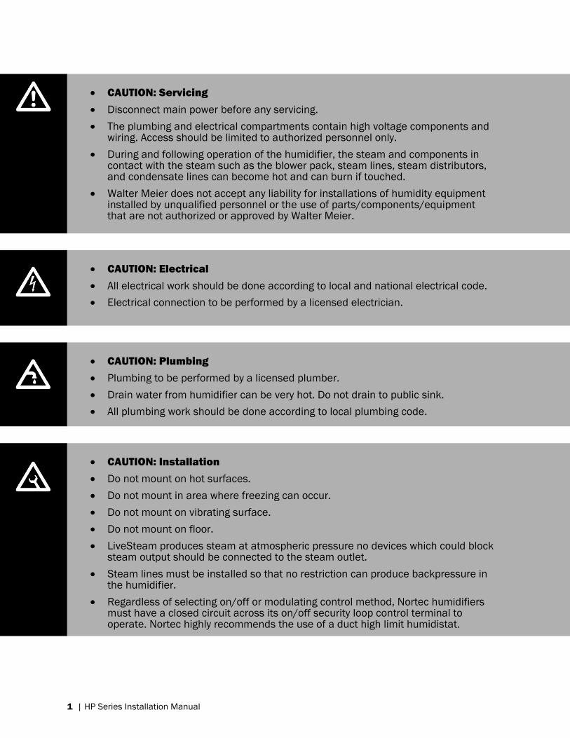
CAUTION: Servicing
Disconnect main power before any servicing.
The plumbing and electrical compartments contain high voltage components andwiring. Access should be limited to authorized personnel only.
During and following operation of the humidifier, the steam and components incontact with the steam such as the blower pack, steam lines, steam distributors,and condensate lines can become hot and can burn if touched.
Walter Meier does not accept any liability for installations of humidity equipmentinstalled by unqualified personnel or the use of parts/components/equipmentthat are not authorized or approved by Walter Meier.
CAUTION: Electrical
All electrical work should be done according to local and national electrical code.
Electrical connection to be performed by a licensed electrician.
CAUTION: Plumbing
Plumbing to be performed by a licensed plumber.
Drain water from humidifier can be very hot. Do not drain to public sink.
All plumbing work should be done according to local plumbing code.
CAUTION: Installation
Do not mount on hot surfaces.
Do not mount in area where freezing can occur.
Do not mount on vibrating surface.
Do not mount on floor.
LiveSteam produces steam at atmospheric pressure no devices which could blocksteam output should be connected to the steam outlet.
Steam lines must be installed so that no restriction can produce backpressure inthe humidifier.
Regardless of selecting on/off or modulating control method, Nortec humidifiersmust have a closed circuit across its on/off security loop control terminal tooperate. Nortec highly recommends the use of a duct high limit humidistat.
Page 5
HP Series Installation Manual | 2
Introduction
HP HVAC (Adiabatic Humidification System)
Congratulations on the purchase of your NORTEC HP HVAC humidification system. This system
was designed to be efficient and reliable, and is manufactured from high quality materials to
provide long trouble free operation. In order for the system to operate as intended it must be
installed properly.
This guide details the design, installation, commissioning, operation, and troubleshooting of the
HP HVAC system. Please take the time to familiarize yourself with this guide before beginning to
ensure that the system is installed the way it was designed. This ensures a long and trouble
free life of the humidifier.
About HP (Adiabatic Humidification System)
The HP (High Pressure) HVAC system is designed to be installed inside an AHU or duct system to
humidify air to a desired relative humidity. Proper humidity levels have been shown to be
important for health and comfort of occupants. Maintaining proper humidity is also important
for many industrial and manufacturing processes.
The HP system uses a series of nozzles to spray a very fine mist of water droplets into an air
stream. During this process the air absorbs moisture increasing its relative humidity levels. As
the water droplets evaporate, they absorb some energy in the form of heat from the air. This
loss of heat causes the air temperature to drop, resulting in a phenomenon known as adiabatic
cooling.
The HP HVAC adiabatic system has 2 effects:
The relative humidity of the air increases (humidification)
The temperature of the air falls (adiabatic cooling)
Humidification of the air is the main goal of the HP HVAC system. The cooling of the air is
secondary and is frequently beneficial since it is „free‟ cooling. In cases where air-cooling is un-
desired, preheating of the air is required.
In general a HP system has the following advantages over other humidification technologies:
Low frequency of maintenance, since there are few moving or expendable parts.
Replacing components is quick and requires minimal system disassembly.
A „free‟ air-cooling benefit from water extracting latent heat from the air.
Receiving and Unpacking Equipment
Check packing slip to ensure ALL material has been delivered.
All material shortages are to be reported to Nortec within 48 hours from receipt of goods.
Nortec assumes no responsibility for any material shortages beyond this period.
Inspect shipping boxes for damage and note on shipping waybill accordingly.
Page 6
3 | HP Series Installation Manual
After unpacking, inspect equipment for damage and if damage is found, notify the shipper
promptly.
All Nortec products are shipped on an F.O.B. factory basis. Any and all damage, breakage or
loss claims are to be made directly to the shipping company.
Absorption Distances
An important consideration in the planning of a HP HVAC system is the absorption distance, or
the distance it takes for the droplets to evaporate inside the HVAC system. The absorption
distance is relative to the air velocity, temperature, atmospheric pressure, and the amount of
water in the incoming air. In applications where space is limited, such as in an air-handler,
precautions should be taken to prevent the wetting of sensitive components downstream.
Components
Nortec Supplied
Nortec will supply the following components:
1 High pressure pump skid
2 Valve controller
3 Valve block assembly
4 Nozzle manifolds
5 In-duct plumbing
6 Mist eliminator (optional)
7 Air proving switch (optional)
8 High limit humidistat (optional)
9 Humidistat (optional)
10 Reverse osmosis system (optional)
Field Supplied
The Installer is responsible for supplying the following:
1 Electrical disconnects
2 All electrical wiring
3 Piping from the RO system to pump module
4 High pressure piping between pump and manifolds
5 Flex hose
6 P-traps
7 Drain funnels
8 Wet duct section (drain pans, wall sections, sealants, fasteners)
9 Pump skid vibration dampening
10 Electricity, water, and airflow
Page 7
HP Series Installation Manual | 4
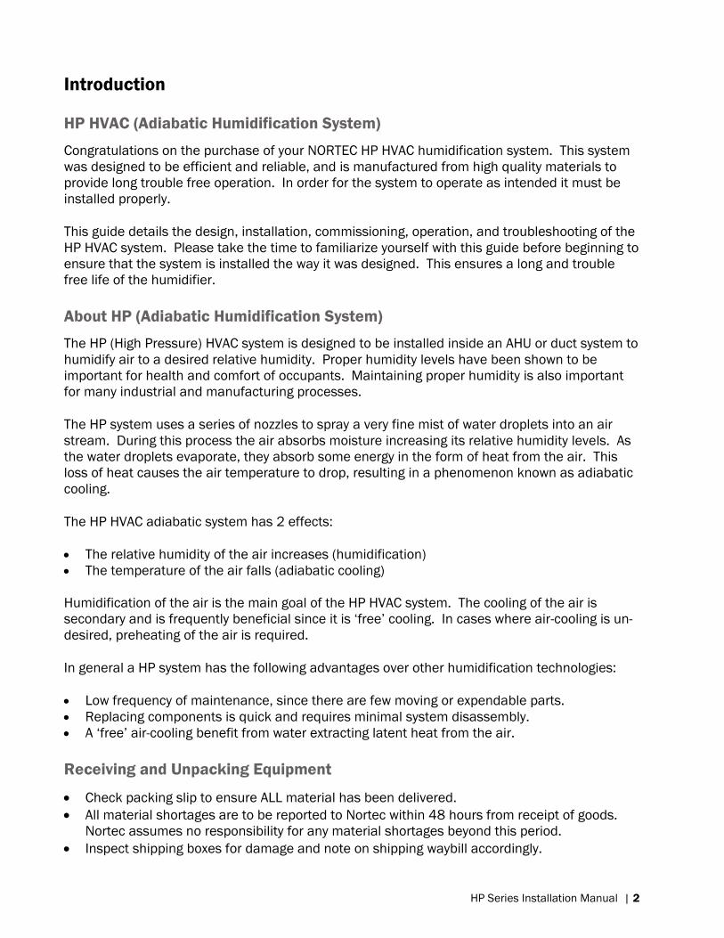
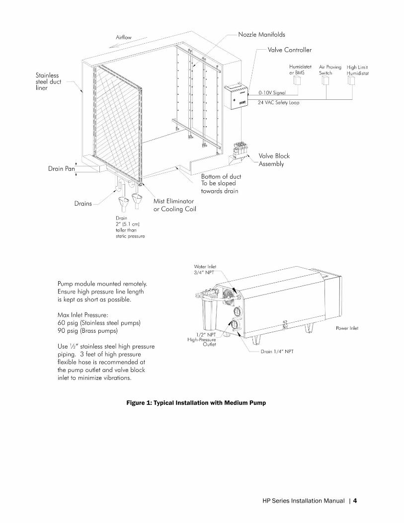
Figure 1: Typical Installation with Medium Pump
Page 8
5 | HP Series Installation Manual
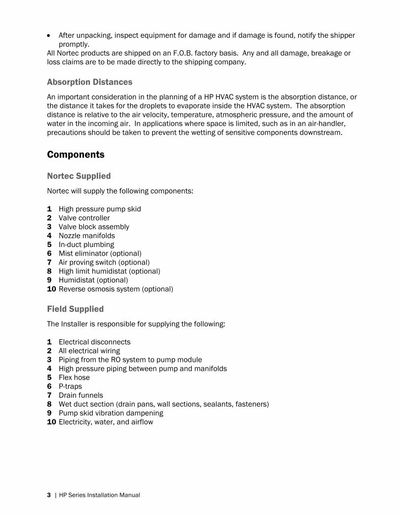
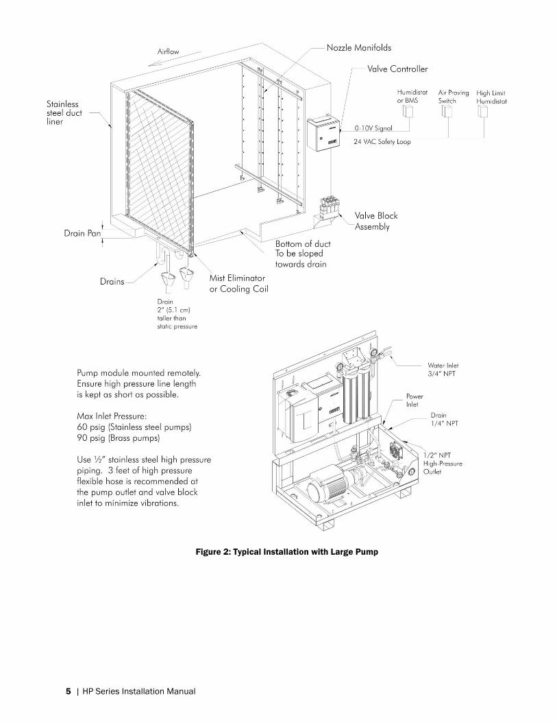
Figure 2: Typical Installation with Large Pump
Page 9
HP Series Installation Manual | 6
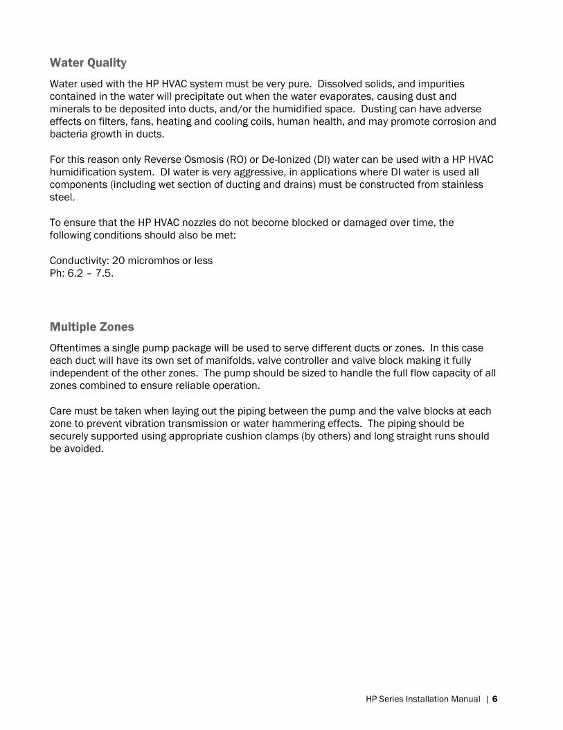
Water Quality
Water used with the HP HVAC system must be very pure. Dissolved solids, and impurities
contained in the water will precipitate out when the water evaporates, causing dust and
minerals to be deposited into ducts, and/or the humidified space. Dusting can have adverse
effects on filters, fans, heating and cooling coils, human health, and may promote corrosion and
bacteria growth in ducts.
For this reason only Reverse Osmosis (RO) or De-Ionized (DI) water can be used with a HP HVAC
humidification system. DI water is very aggressive, in applications where DI water is used all
components (including wet section of ducting and drains) must be constructed from stainless
steel.
To ensure that the HP HVAC nozzles do not become blocked or damaged over time, the
following conditions should also be met:
Conductivity: 20 micromhos or less
Ph: 6.2 – 7.5.
Multiple Zones
Oftentimes a single pump package will be used to serve different ducts or zones. In this case
each duct will have its own set of manifolds, valve controller and valve block making it fully
independent of the other zones. The pump should be sized to handle the full flow capacity of all
zones combined to ensure reliable operation.
Care must be taken when laying out the piping between the pump and the valve blocks at each
zone to prevent vibration transmission or water hammering effects. The piping should be
securely supported using appropriate cushion clamps (by others) and long straight runs should
be avoided.
Page 10
7 | HP Series Installation Manual
Installation
Page 11
HP Series Installation Manual | 8
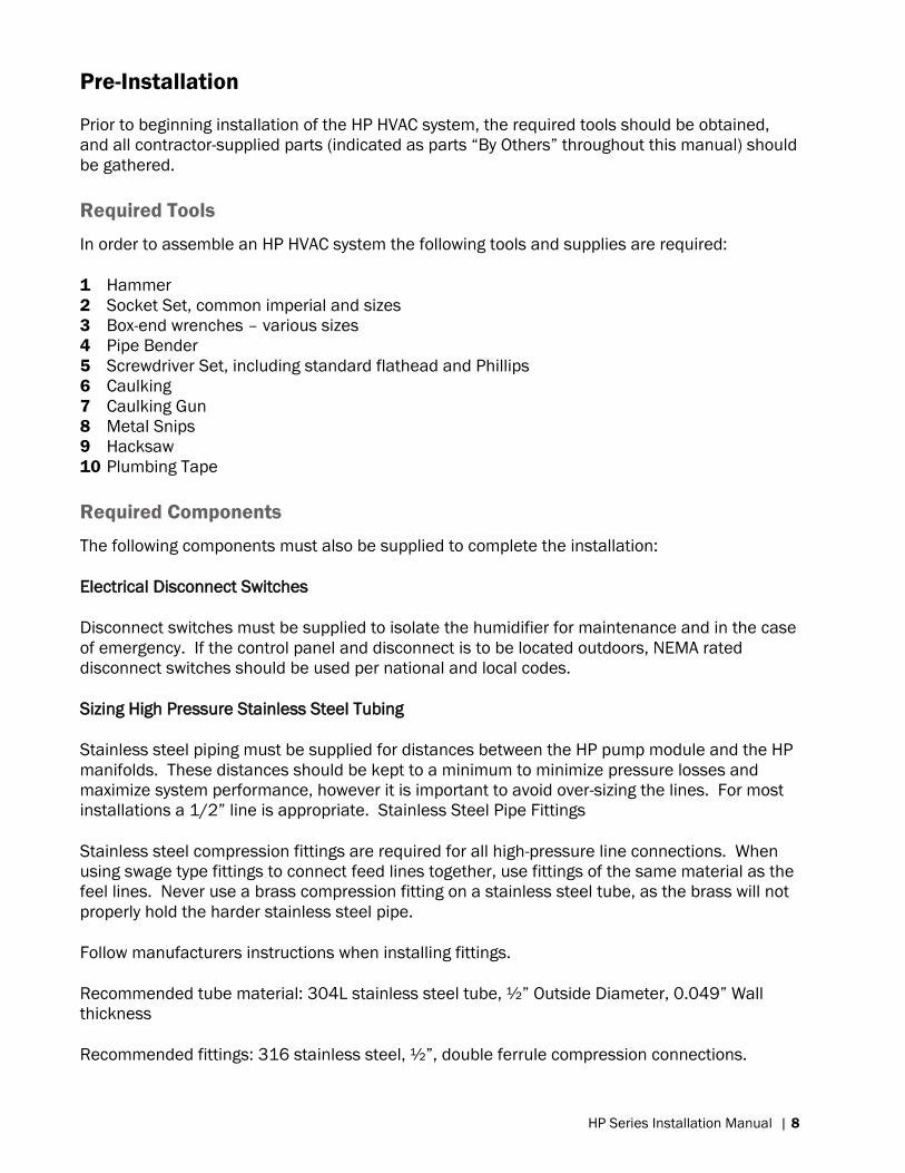
Pre-Installation
Prior to beginning installation of the HP HVAC system, the required tools should be obtained,
and all contractor-supplied parts (indicated as parts “By Others” throughout this manual) should
be gathered.
Required Tools
In order to assemble an HP HVAC system the following tools and supplies are required:
1 Hammer
2 Socket Set, common imperial and sizes
3 Box-end wrenches – various sizes
4 Pipe Bender
5 Screwdriver Set, including standard flathead and Phillips
6 Caulking
7 Caulking Gun
8 Metal Snips
9 Hacksaw
10 Plumbing Tape
Required Components
The following components must also be supplied to complete the installation:
Electrical Disconnect Switches
Disconnect switches must be supplied to isolate the humidifier for maintenance and in the case
of emergency. If the control panel and disconnect is to be located outdoors, NEMA rated
disconnect switches should be used per national and local codes.
Sizing High Pressure Stainless Steel Tubing
Stainless steel piping must be supplied for distances between the HP pump module and the HP
manifolds. These distances should be kept to a minimum to minimize pressure losses and
maximize system performance, however it is important to avoid over-sizing the lines. For most
installations a 1/2” line is appropriate. Stainless Steel Pipe Fittings
Stainless steel compression fittings are required for all high-pressure line connections. When
using swage type fittings to connect feed lines together, use fittings of the same material as the
feel lines. Never use a brass compression fitting on a stainless steel tube, as the brass will not
properly hold the harder stainless steel pipe.
Follow manufacturers instructions when installing fittings.
Recommended tube material: 304L stainless steel tube, ½” Outside Diameter, 0.049” Wall
thickness
Recommended fittings: 316 stainless steel, ½”, double ferrule compression connections.
Page 12
9 | HP Series Installation Manual
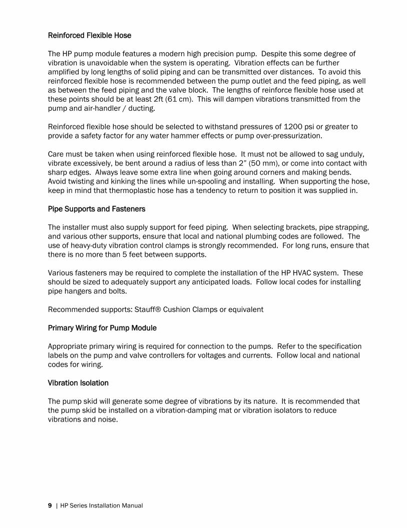
Reinforced Flexible Hose
The HP pump module features a modern high precision pump. Despite this some degree of
vibration is unavoidable when the system is operating. Vibration effects can be further
amplified by long lengths of solid piping and can be transmitted over distances. To avoid this
reinforced flexible hose is recommended between the pump outlet and the feed piping, as well
as between the feed piping and the valve block. The lengths of reinforce flexible hose used at
these points should be at least 2ft (61 cm). This will dampen vibrations transmitted from the
pump and air-handler / ducting.
Reinforced flexible hose should be selected to withstand pressures of 1200 psi or greater to
provide a safety factor for any water hammer effects or pump over-pressurization.
Care must be taken when using reinforced flexible hose. It must not be allowed to sag unduly,
vibrate excessively, be bent around a radius of less than 2” (50 mm), or come into contact with
sharp edges. Always leave some extra line when going around corners and making bends.
Avoid twisting and kinking the lines while un-spooling and installing. When supporting the hose,
keep in mind that thermoplastic hose has a tendency to return to position it was supplied in.
Pipe Supports and Fasteners
The installer must also supply support for feed piping. When selecting brackets, pipe strapping,
and various other supports, ensure that local and national plumbing codes are followed. The
use of heavy-duty vibration control clamps is strongly recommended. For long runs, ensure that
there is no more than 5 feet between supports.
Various fasteners may be required to complete the installation of the HP HVAC system. These
should be sized to adequately support any anticipated loads. Follow local codes for installing
pipe hangers and bolts.
Recommended supports: Stauff® Cushion Clamps or equivalent
Primary Wiring for Pump Module
Appropriate primary wiring is required for connection to the pumps. Refer to the specification
labels on the pump and valve controllers for voltages and currents. Follow local and national
codes for wiring.
Vibration Isolation
The pump skid will generate some degree of vibrations by its nature. It is recommended that
the pump skid be installed on a vibration-damping mat or vibration isolators to reduce
vibrations and noise.
Page 13
HP Series Installation Manual | 10
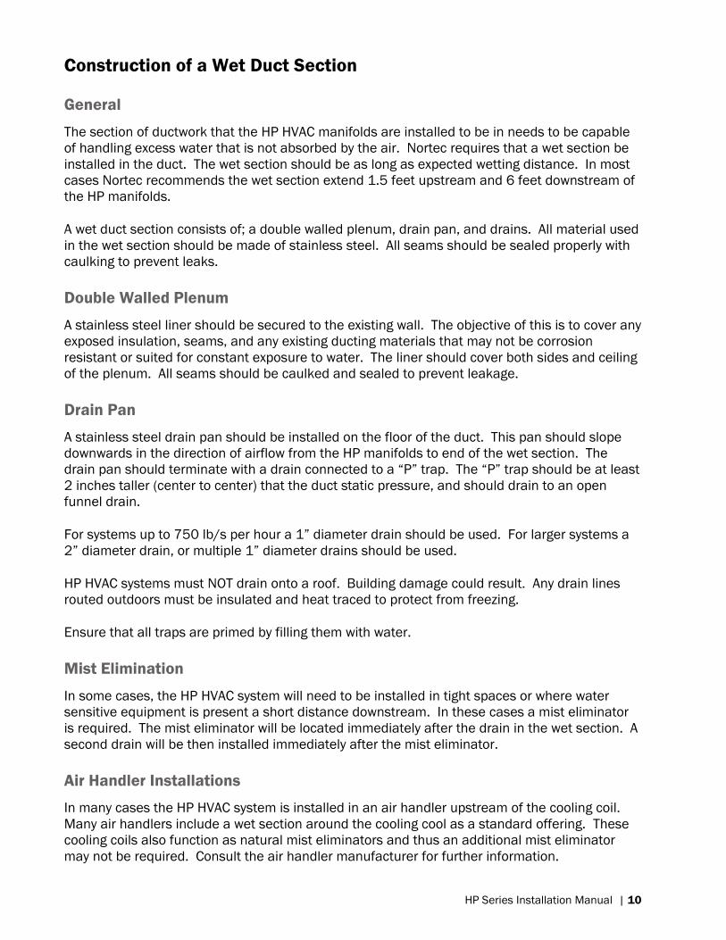
Construction of a Wet Duct Section
General
The section of ductwork that the HP HVAC manifolds are installed to be in needs to be capable
of handling excess water that is not absorbed by the air. Nortec requires that a wet section be
installed in the duct. The wet section should be as long as expected wetting distance. In most
cases Nortec recommends the wet section extend 1.5 feet upstream and 6 feet downstream of
the HP manifolds.
A wet duct section consists of; a double walled plenum, drain pan, and drains. All material used
in the wet section should be made of stainless steel. All seams should be sealed properly with
caulking to prevent leaks.
Double Walled Plenum
A stainless steel liner should be secured to the existing wall. The objective of this is to cover any
exposed insulation, seams, and any existing ducting materials that may not be corrosion
resistant or suited for constant exposure to water. The liner should cover both sides and ceiling
of the plenum. All seams should be caulked and sealed to prevent leakage.
Drain Pan
A stainless steel drain pan should be installed on the floor of the duct. This pan should slope
downwards in the direction of airflow from the HP manifolds to end of the wet section. The
drain pan should terminate with a drain connected to a “P” trap. The “P” trap should be at least
2 inches taller (center to center) that the duct static pressure, and should drain to an open
funnel drain.
For systems up to 750 lb/s per hour a 1” diameter drain should be used. For larger systems a
2” diameter drain, or multiple 1” diameter drains should be used.
HP HVAC systems must NOT drain onto a roof. Building damage could result. Any drain lines
routed outdoors must be insulated and heat traced to protect from freezing.
Ensure that all traps are primed by filling them with water.
Mist Elimination
In some cases, the HP HVAC system will need to be installed in tight spaces or where water
sensitive equipment is present a short distance downstream. In these cases a mist eliminator
is required. The mist eliminator will be located immediately after the drain in the wet section. A
second drain will be then installed immediately after the mist eliminator.
Air Handler Installations
In many cases the HP HVAC system is installed in an air handler upstream of the cooling coil.
Many air handlers include a wet section around the cooling cool as a standard offering. These
cooling coils also function as natural mist eliminators and thus an additional mist eliminator
may not be required. Consult the air handler manufacturer for further information.
Page 14
11 | HP Series Installation Manual
The above is not true for a heating coil; most heating coils are not designed to be wetted. If
installing upstream of a heating coil a mist eliminator must be used.
Pump Module
The pump module location should be selected with the following guidelines in mind:
Available Power: The pump should be located close to its supply power source.
Available Water: The pump should be located close to its RO or DI water source.
Proximity to Manifolds: The pump should be located as close as possible to the manifolds to
minimize pressure losses in the lines. See Table 4 Piping Pressure Losses for more information.
Available Drain: To prevent damage to other equipment in the event that the pump module
should leak, it is recommended that the pump module be located near a floor drain.
Proper Ventilation: The pump will generate heat during operation. Covered pump modules
include cooling fans, while uncovered pump modules typically rely on natural airflow in the room
for cooling. Ensure that the pump module is located in an area where it can receive a
reasonable amount of airflow. Avoid installing other equipment on top of or in front of the pump
module.
Occupants: The pump will generate some noise and vibration during operation. The pump
should be located somewhere in a place noise and vibrations will not disturb occupants of the
building. Installing the pump module on vibration isolators is recommended to minimize
vibrations. Optional pump covers are available for large pump skids to minimize noise.
Installing the Pump
Move the pump to the location selected and secure it to the floor.
Confirm that primary power source matches the specification label on the pump. It is strongly
recommended that the pump module have a dedicated power supply to prevent brownouts
when the pump module starts. Install a manual disconnect switch for the pump module.
Install connection to the reverse osmosis / de-ionized water supply. Ensure that supply water
pressure from the RO or DI water system is at least 25 psi (1.7 bar) at the inlet to the pump
skid. Never exceed 60 psig inlet pressure (Danfoss Stainless Steel Pump) or 90 psig (Giant
Brass Pumps). The water system capacity must be a minimum of 120% of the humidification
system capacity.
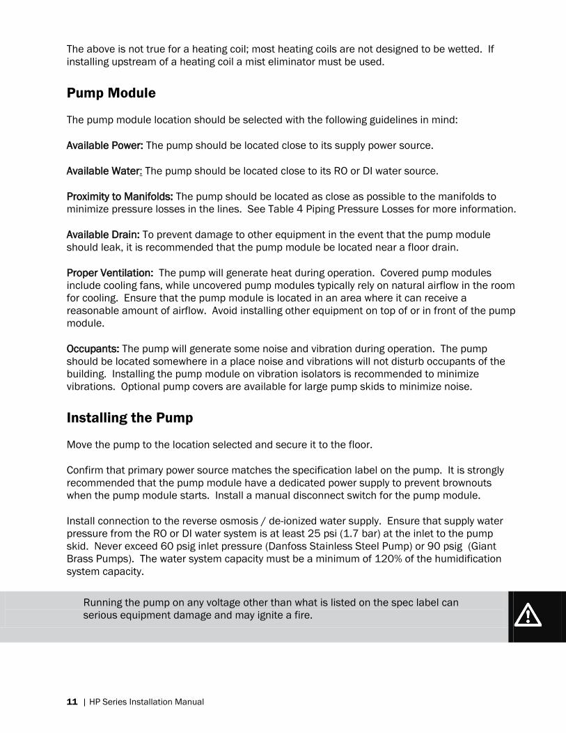
Running the pump on any voltage other than what is listed on the spec label can
serious equipment damage and may ignite a fire.
Page 15
HP Series Installation Manual | 12
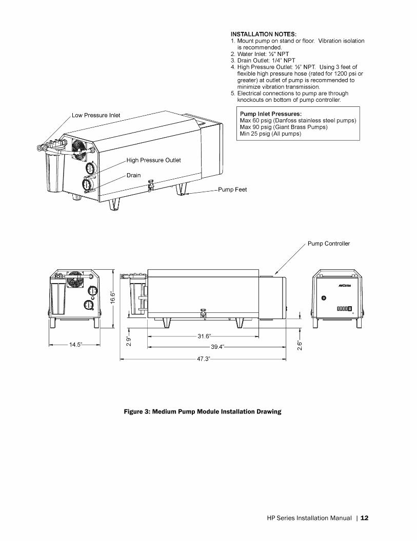
Figure 3: Medium Pump Module Installation Drawing
Page 16
13 | HP Series Installation Manual
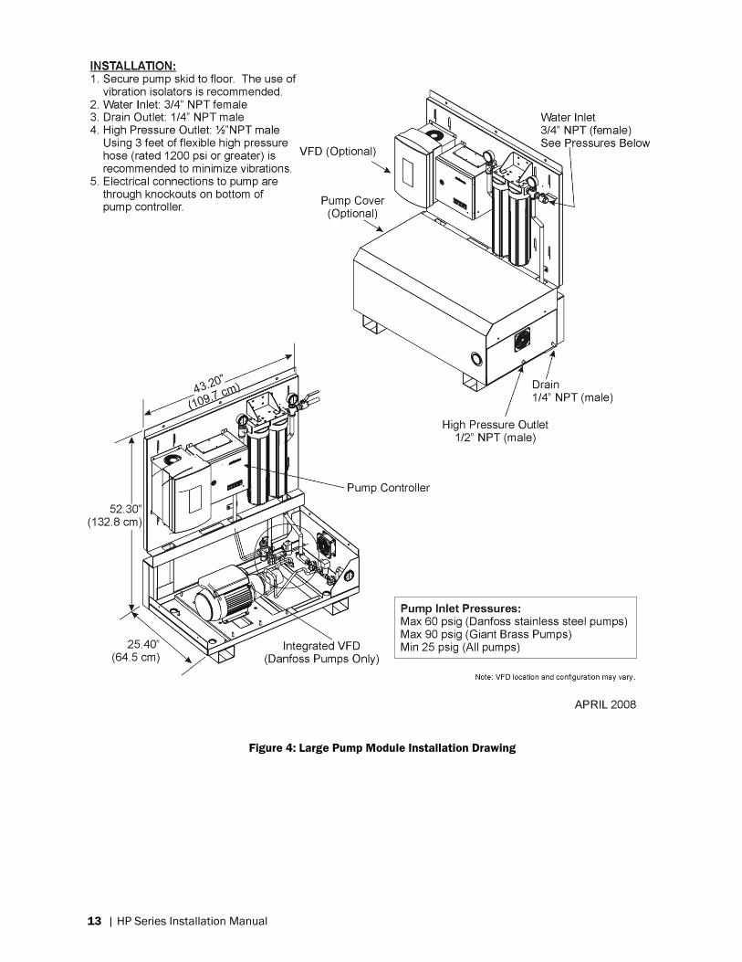
Figure 4: Large Pump Module Installation Drawing
Page 17
HP Series Installation Manual | 14
Only reverse osmosis or de-ionized water can be used with the HP HVAC system.
Connect the primary electrical supply to the pump. Refer to the wiring diagram located in this
manual.
Installation of the HP HVAC Manifolds
The HP HVAC system uses vertical manifolds with that spray into the airstream. These
manifolds are supported at both the top and the bottom by horizontal mounting rails. Since
each system is sized and built to a certain duct size, some test fitting will be necessary to
properly install the rails.
If a wet section has not yet been constructed in the duct or air-handler, it should be constructed
before the humidifier installation has started.
If the duct is greater than 8 feet in width, install mounting rail extensions (P/N 1510135) onto
the mounting rails.
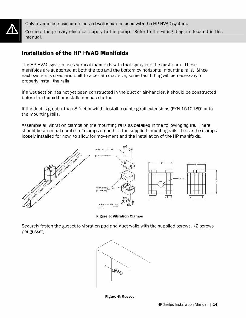
Assemble all vibration clamps on the mounting rails as detailed in the following figure. There
should be an equal number of clamps on both of the supplied mounting rails. Leave the clamps
loosely installed for now, to allow for movement and the installation of the HP manifolds.
Figure 5: Vibration Clamps
Securely fasten the gusset to vibration pad and duct walls with the supplied screws. (2 screws
per gusset).
Figure 6: Gusset
Page 18
15 | HP Series Installation Manual
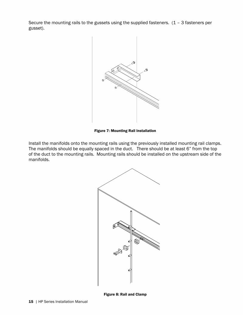
Secure the mounting rails to the gussets using the supplied fasteners. (1 – 3 fasteners per
gusset).
Figure 7: Mounting Rail Installation
Install the manifolds onto the mounting rails using the previously installed mounting rail clamps.
The manifolds should be equally spaced in the duct. There should be at least 6” from the top
of the duct to the mounting rails. Mounting rails should be installed on the upstream side of the
manifolds.
Figure 8: Rail and Clamp
Page 19
HP Series Installation Manual | 16
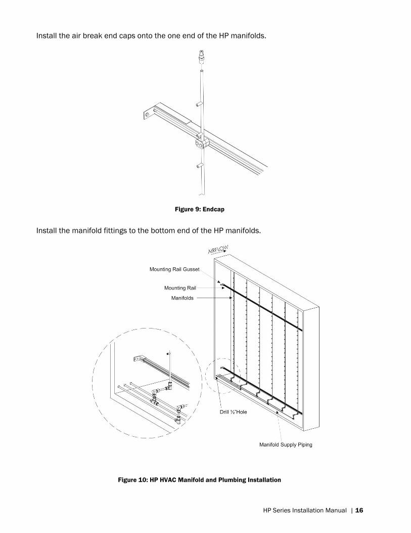
Install the air break end caps onto the one end of the HP manifolds.
Figure 9: Endcap
Install the manifold fittings to the bottom end of the HP manifolds.
Figure 10: HP HVAC Manifold and Plumbing Installation
Page 20
17 | HP Series Installation Manual
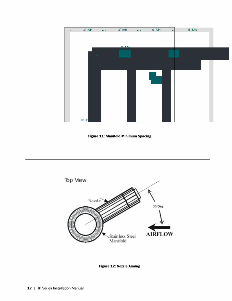
ZO NE VALVE
ASSEM BLY
4” Min
6” Min
4” Min 4” Min4” Min
6” Min
Figure 11: Manifold Minimum Spacing
Figure 12: Nozzle Aiming
Page 21
HP Series Installation Manual | 18
Installation of the Piping Between Valve Block and Manifolds
The valve block should be located in such a way as to feed the manifolds using the supplied
piping and fittings. Refer to the piping diagram for your specific unit (On/Off, 3 Stage, 6 Stage).
For High-Resolution HP HVAC installations, refer to the piping diagram included in the
documentation package from proper piping.
It is helpful to place the valve block in its approximate location to assist with measuring piping
lengths and placing fittings. The valve block can be installed in the duct or outside of the duct.
The piping between the valve block and the manifolds should have a slight decline towards the
valve blocks. This allows for water to drain from the manifolds and lines when the system is not
in use.
In installations where water hammer is of concern, it is recommended to install some flexible
piping between the valve block and the manifold feed lines. Using flexible feed lines between
the valve block and the manifold supply piping can also simplify the installation procedure and
allow for some misalignment among the manifold feed lines and the valve block. The valves are
threaded to accept ½” G fittings.
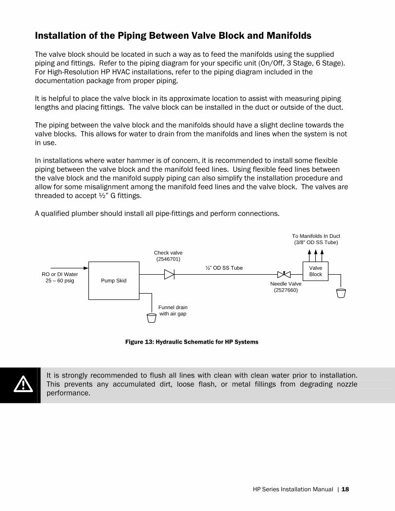
A qualified plumber should install all pipe-fittings and perform connections.
Pump Skid
Valve
BlockRO or DI Water
25 – 60 psig
Funnel drain
with air gap
Check valve
(2546701)
½” OD SS Tube
Needle Valve
(2527660)
To Manifolds In Duct
(3/8" OD SS Tube)
Figure 13: Hydraulic Schematic for HP Systems
It is strongly recommended to flush all lines with clean with clean water prior to installation.
This prevents any accumulated dirt, loose flash, or metal fillings from degrading nozzle
performance.
Page 22
19 | HP Series Installation Manual
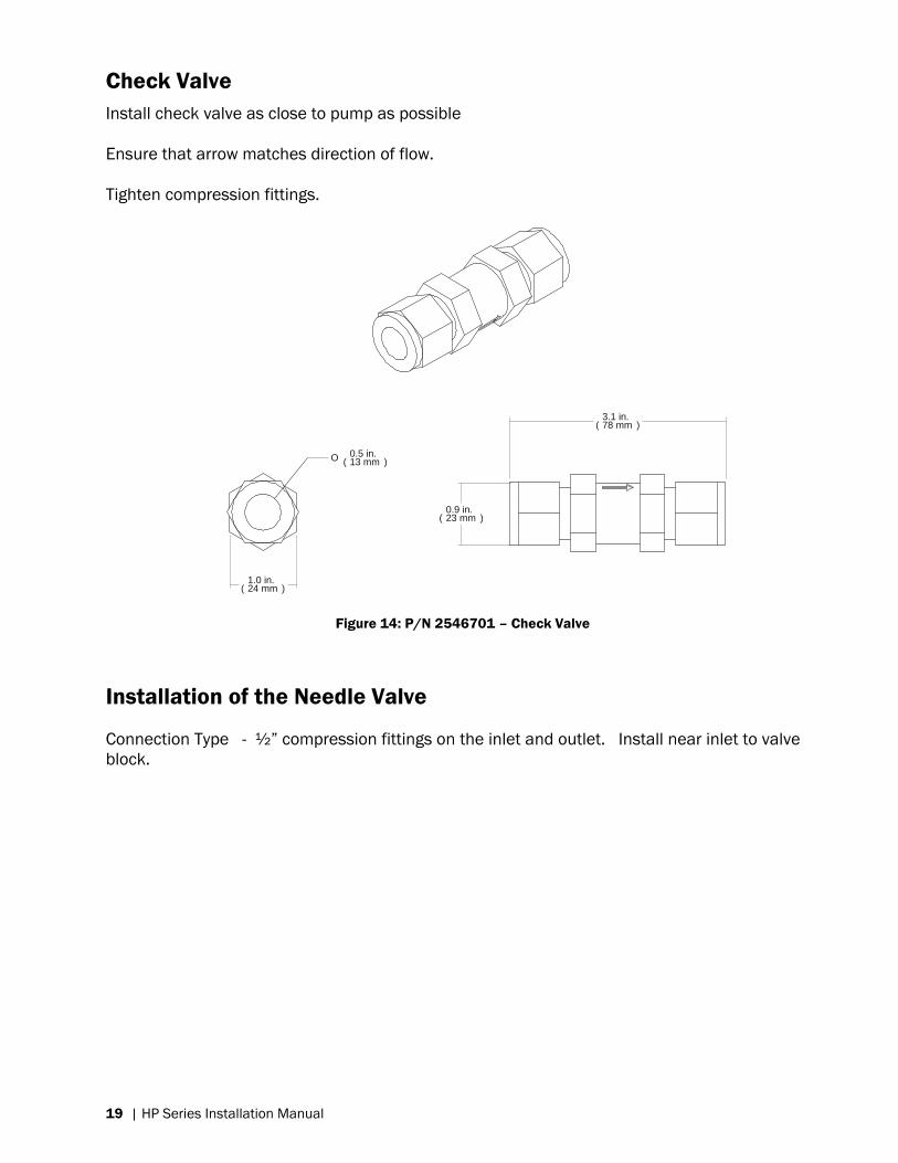
Check Valve
Install check valve as close to pump as possible
Ensure that arrow matches direction of flow.
Tighten compression fittings.
3.1 in.( 78 mm )
0.9 in.( 23 mm )
O 0.5 in.( 13 mm )
1.0 in.( 24 mm )
Figure 14: P/N 2546701 – Check Valve
Installation of the Needle Valve
Connection Type - ½” compression fittings on the inlet and outlet. Install near inlet to valve
block.
Page 23
HP Series Installation Manual | 20
Installation of the Valve Block
Please refer to the valve block schematics for your specific unit in the Wiring Diagram Section
for clarification of the below instructions. For High-Resolution systems, please refer to the
schematics that were included in the documentation package.
Securely fasten the valve block in place. The valve block can either be installed inside or
outside of the duct, however installing in-duct reduces the quantity of holes which must be
drilled through the duct.
The valves have threaded connections with a ½” G thread. Connect the high-pressure supply
line from the pump to the valve block inlet. It is recommended to use a 2 foot flexible hose
connection between the pump supply line and soft charge valve block. This flexible line
prevents the transmission of vibrations through piping. If the pump is only a short distance
away it is recommended to use high pressure flexible hose for the entire run.
Vibrations can be transmitted from air-handlers, the HP pump modules, or other mechanical
room equipment, it is strongly recommended to use a 2 ft (0.6 m) length of flexible piping at
the valve blocks, and HP pump module to protect the equipment from damage.
Install drain piping on the valve block. When the manifolds are not in use, they are drained to
prevent stagnant water, which can lead to microbial growth. The volume of water drained is
equal to the volume of the manifolds and their supply lines. The drain line can be solid pipe or
flexible hose for convenience. It must flow to an open-air funnel or nearby floor drain. The
water can also be reclaimed and returned to the RO system for processing.
The drain line must flow to an open-air funnel. Solid connection to a drain can result in
backflow, failure to drain, and dripping nozzles.
Page 24
21 | HP Series Installation Manual
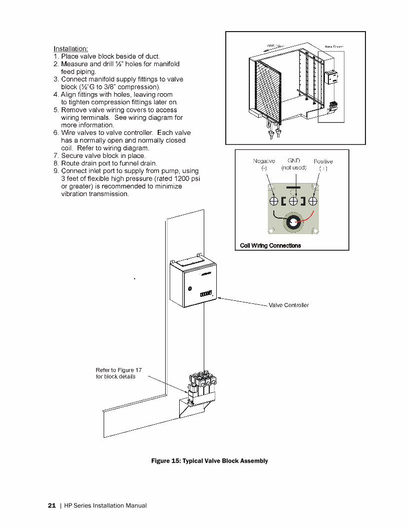
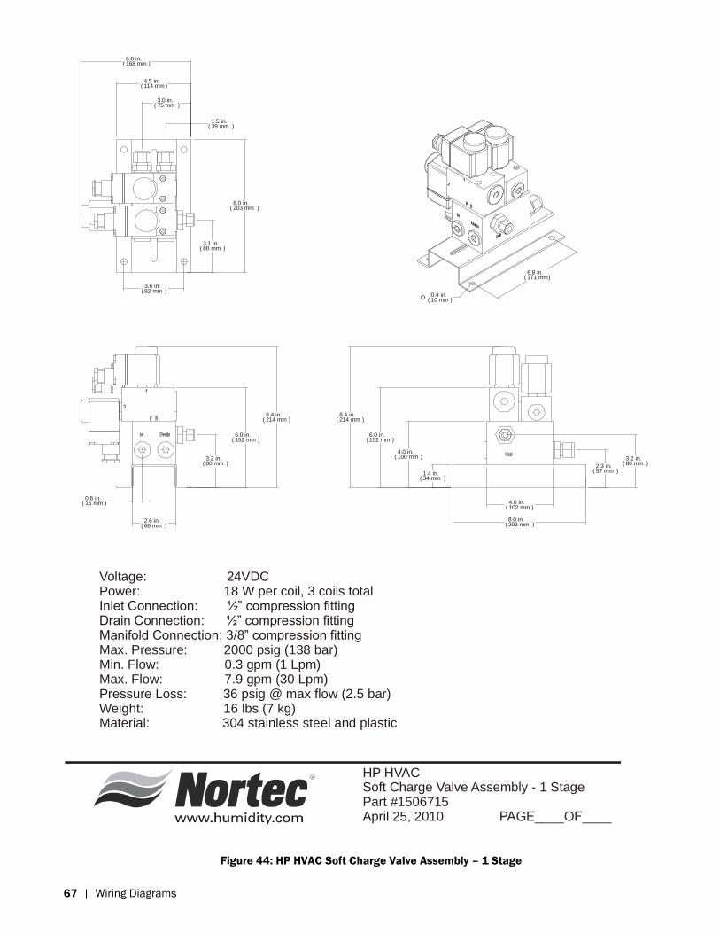
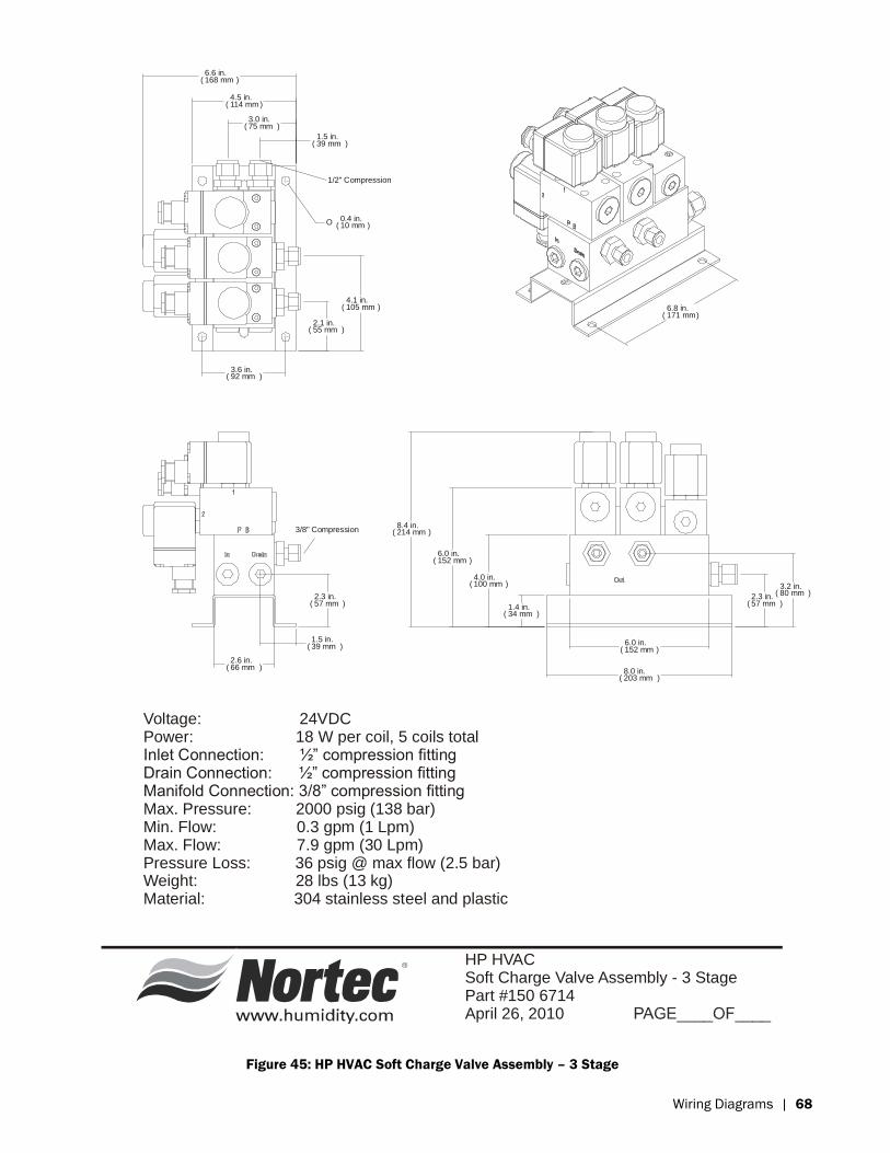
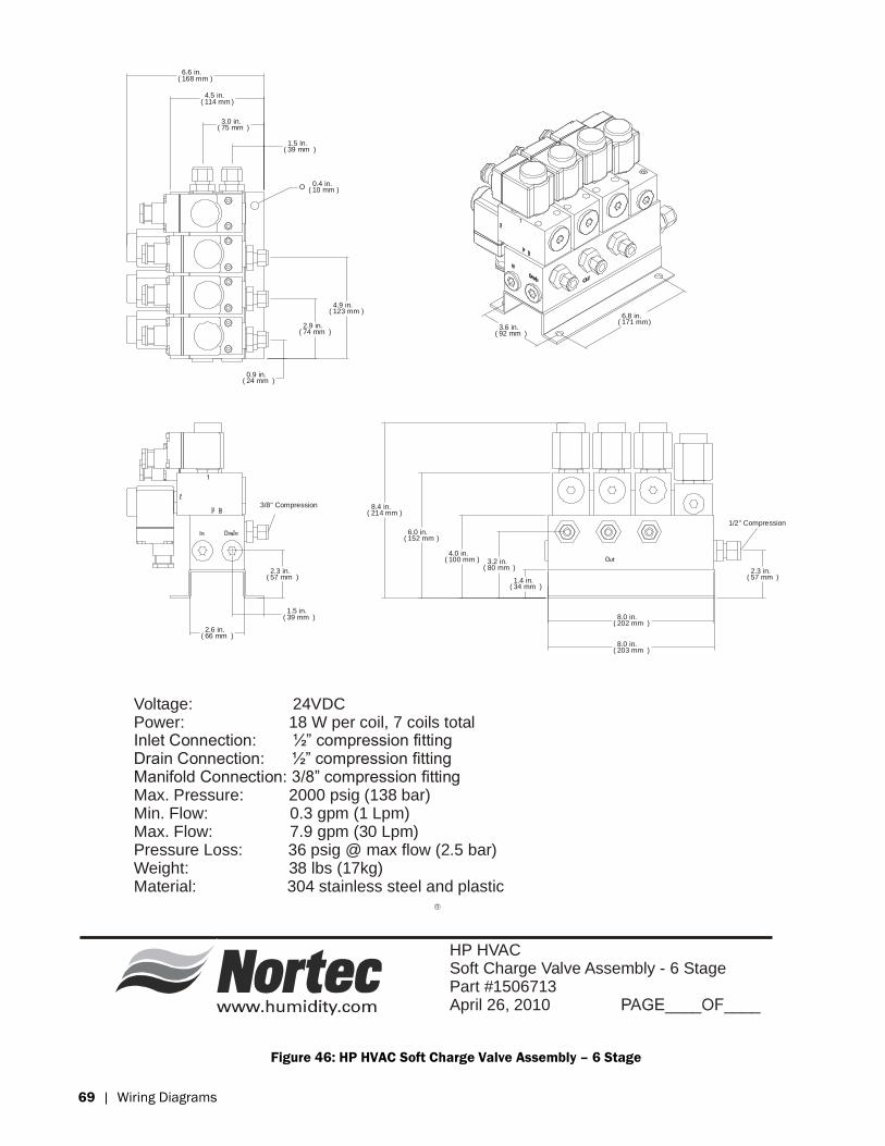
Figure 15: Typical Valve Block Assembly
Page 25
HP Series Installation Manual | 22
High Pressure Piping
Install high pressure piping between the valve blocks and the HP pump module. The valve
blocks are threaded to accept ½” G fittings. For short runs, it is recommended to install flexible
piping for this purpose. For longer runs use flexible piping at the pump outlet and valve inlet to
minimize vibration transmission. Ensure that flexible piping is rated for pressure and water type
in the application.
Flush piping prior to installation to clear any debris. Debris will inhibit nozzle operation.
Low Pressure Piping
Low-pressure piping should be connected to the inlet of the pump. Ensure that water inlet
pressure is between 20 and 100 psig.
The pump inlet accepts a 3/4” NPT threaded connection. The low-pressure inlet connection
can be a flexible hose or a stainless steel pipe. Stainless steel pipe is recommended for longer
runs of piping, while flexible hose is recommended for shorter runs. If stainless lines are used,
it is recommended to install a length of flexible hose between the metal piping and the pump
inlet to minimize vibration transmission.
Flush low pressure piping with water prior to installation to clear any debris.
A drain line for the pump must also be connected; this line should connect flow to an open-air
funnel or floor drain to prevent backpressure on the pump. Water can also be reclaimed and
returned to the RO or DI system for processing. The pump drain port is threaded to accept a ¼”
NPT connection.
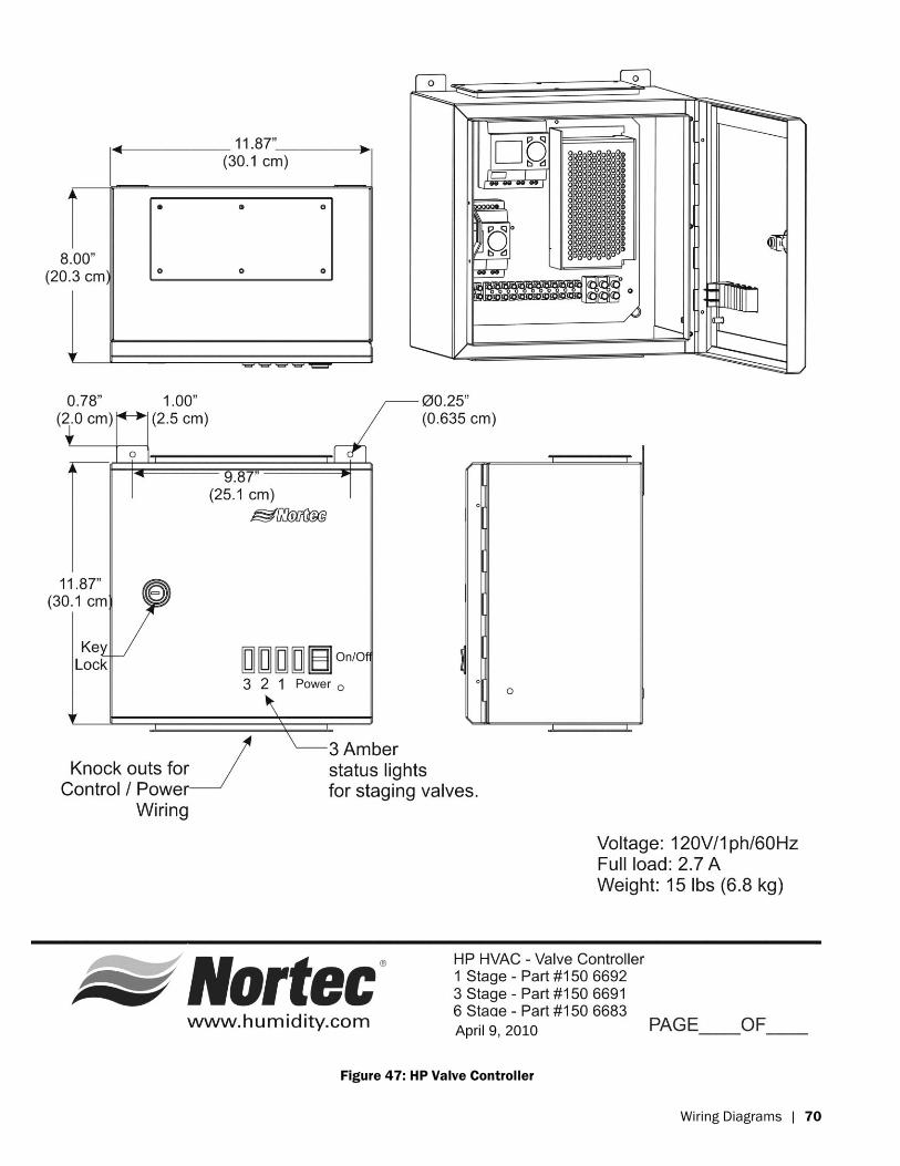
Valve Controller Installation
The valve controller should be located near the pump and valve blocks. Refer to schematics
for valve controller dimensions.
Using suitable screws, mount the control panel at a convenient height on a wall or suitable
structure.
Refer to the spec label on the valve controller; ensure that the voltage matches the electrical
voltage being supplied to it. In most cases this voltage will be 120VAC 60Hz single phase. At
this voltage, the controller draws 2.7A (except high resolution systems). Install a dedicated
disconnect on the electricity source to allow the controller to be isolated.
Page 26
23 | HP Series Installation Manual
Leave the disconnect in an open (off) position until all wiring has been completed
Connect the input voltage to the valve controller. Input voltage connections are clearly indicated
by labels inside of the valve controller box.
Wiring of the System
On-Off Safety Devices
Safety switches are available to prevent the humidifier from operating excessively or at incorrect
times. These may include; air proving switches (A), duct high limit switches (B), disable switches
(C), other on-off type devices.
Install these devices in accordance with their respective installation instructions. All on-off style
devices should be wired in series and connected between terminals 1 and 2 on the valve
controller terminal strip.
The circuit between terminals 1 and 2 is a 24VDC circuit, 16 or 18 AWG standard wire should
be used for this purpose.
The humidifier will only operate if there is continuity between terminals 1 and 2. If no on/off style
safeties are to be used, install a jumper between terminals 1 and 2.
Page 27
HP Series Installation Manual | 24
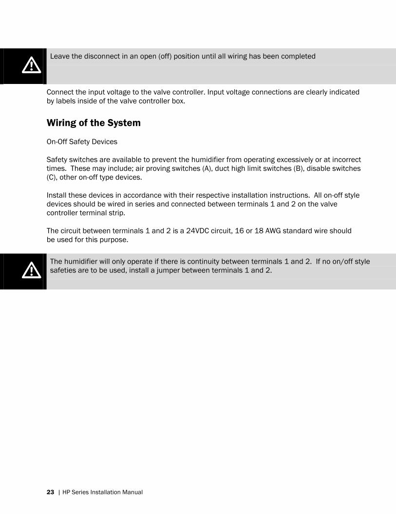
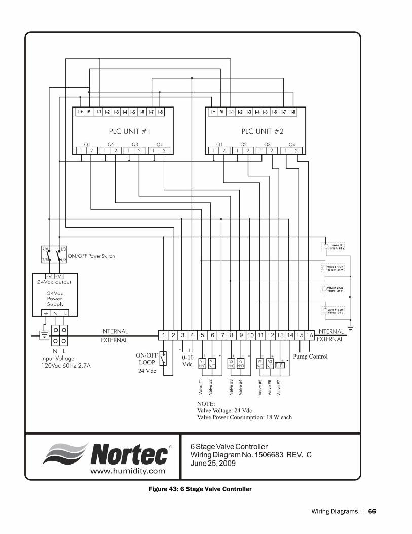
Figure 16: HP HVAC Terminal Strip
Installation Notes
Connect wiring as shown. Use 16 or 18 AWG standard wire.
For multiple On/Off safeties, connect devices in series.
Valve 2 and 3 connections not used for single stage systems.
Flush valve is always connected to valve controller terminals 13 (+) and 14 (-)
Pump controller terminal 9 (GND) is an available accessory ground.
Single Stage Control Options
Time proportioning control: Connect a 0-10 humidistat to valve terminals 3 and 4.
On/Off Control: Connect a humidistat between valve controller terminals 1 and 2. Also connect
a jumper between terminals 1 and 3.
Page 28
25 | HP Series Installation Manual
Pump Controller Wiring Notes
Connections to Nortec Valve Controller
The pump controller can accept control input from many different valve controllers at once. This
is useful for cases when a single large pump skid is used to supply high-pressure water to
different zones / manifold groups. For example, 1 large pump skid supplies water to 3 different
air-handlers, each with their own manifolds, valves, and valve controller.
If there are more than 4 valve controllers, additional controllers can be added by doubling up
wires on the pump controller terminal strip. For example; valve controller 5 would share
terminals 1 and 5 with valve controller 1.
Connections to Valve Controllers by Others
Non-Nortec valve controllers can be used with the HP HVAC system. In these cases the valve
controller is wired to the pump controller, as it would be with a Nortec valve controller. The
valve controller need only close the loop, and does not need to provide a voltage or current. If
the valve controller does provide a signal, it should be wired to a relay which will then close the
pump controller loop.
Remote Monitoring
The pump controller terminal strip features several sets of dry contacts to allow for connections
to a building management system, status lights, or other types of equipment. They are
controlled by a relay and activated under certain conditions. Wire gauge is determined by the
equipment to be using the contacts. Refer to the manufacturers recommendations.
On (Terminals 10 and 11): Closed when the HP HVAC system is powered on and ready.
Active (Terminals 12 and 13): Closed when the HP HVAC system is humidifying.
Service (Terminals 14 and 15): Closed when the HP HVAC system requires regular
maintenance. (See Chapter X for service information.)
Fault (Terminals 16, 17 and 18): Terminal 16 is normally open and closes when an operation
fault occurs. Terminal 18 is normally closed and opens when an operational fault occurs.
Terminal 17 is a common terminal for both cases.
Page 29
HP Series Installation Manual | 26
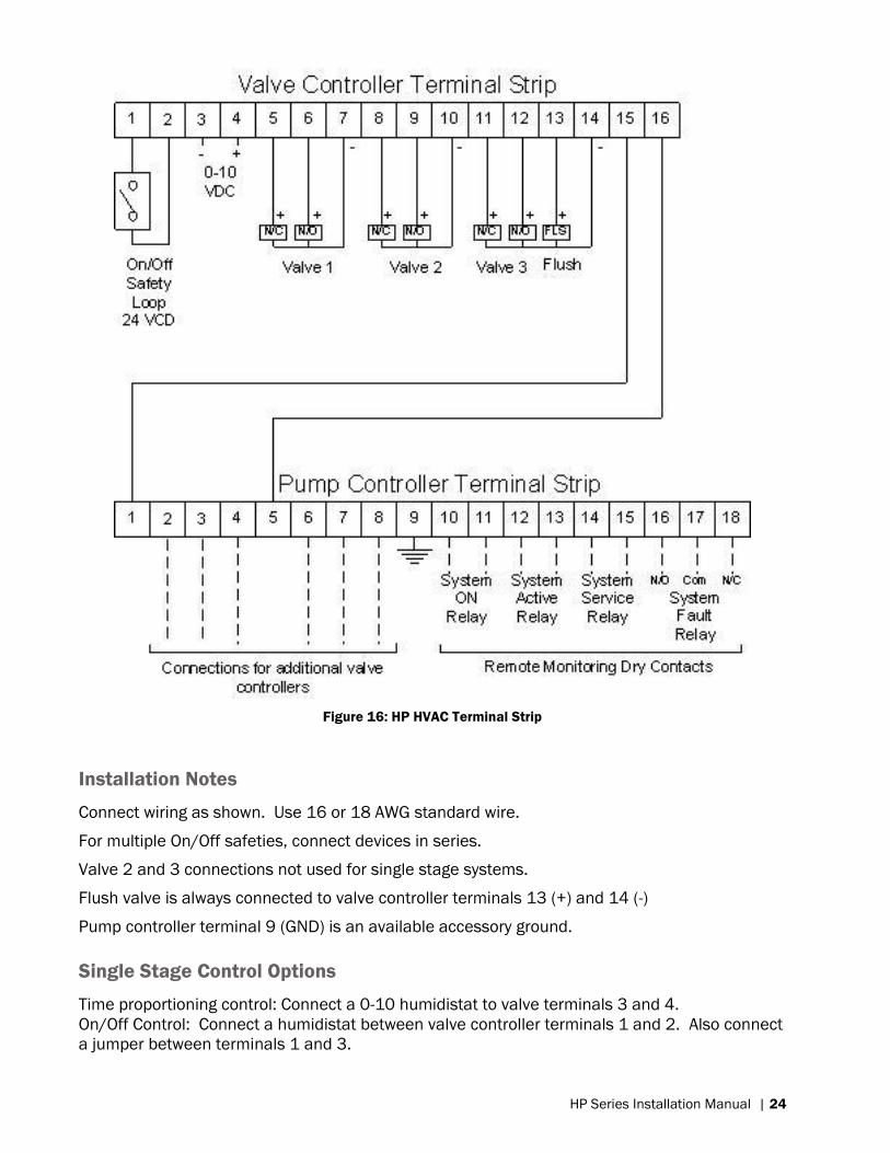
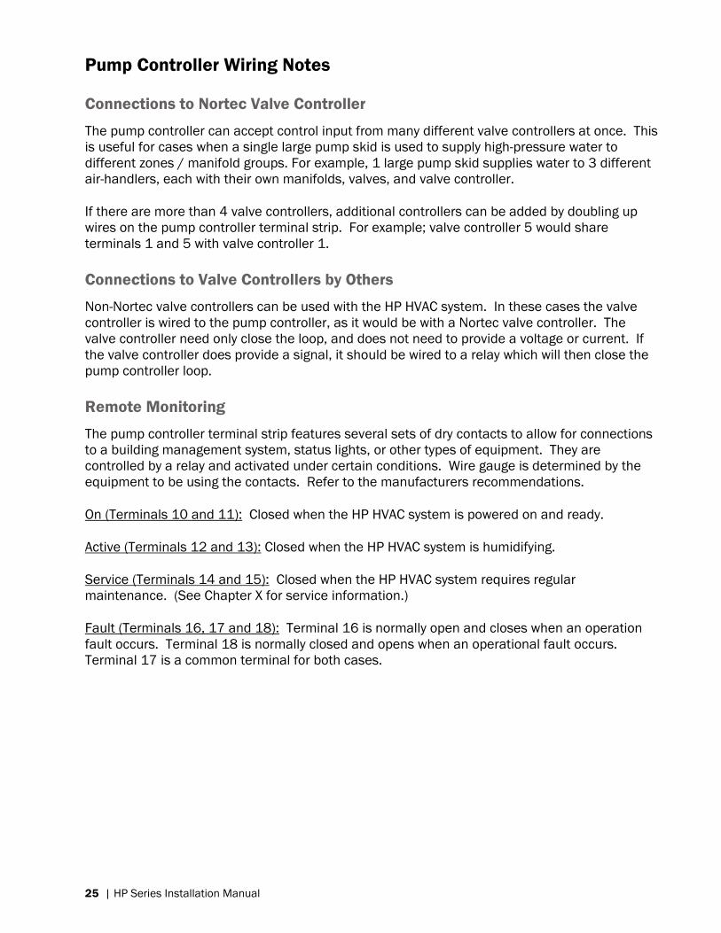
Figure 17: Valve Coils
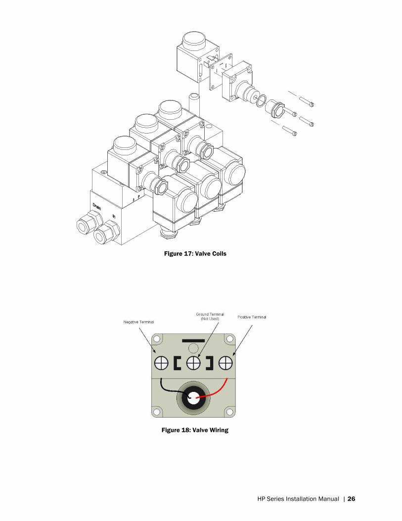
Figure 18: Valve Wiring
Page 30
27 | HP Series Installation Manual
Mist Eliminator Installation
General
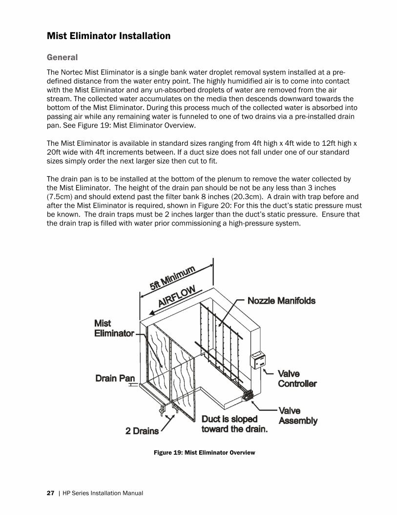
The Nortec Mist Eliminator is a single bank water droplet removal system installed at a pre-
defined distance from the water entry point. The highly humidified air is to come into contact
with the Mist Eliminator and any un-absorbed droplets of water are removed from the air
stream. The collected water accumulates on the media then descends downward towards the
bottom of the Mist Eliminator. During this process much of the collected water is absorbed into
passing air while any remaining water is funneled to one of two drains via a pre-installed drain
pan. See Figure 19: Mist Eliminator Overview.
The Mist Eliminator is available in standard sizes ranging from 4ft high x 4ft wide to 12ft high x
20ft wide with 4ft increments between. If a duct size does not fall under one of our standard
sizes simply order the next larger size then cut to fit.
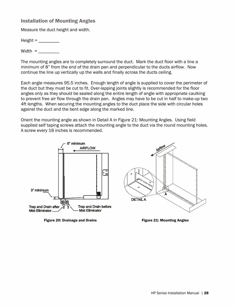
The drain pan is to be installed at the bottom of the plenum to remove the water collected by
the Mist Eliminator. The height of the drain pan should be not be any less than 3 inches
(7.5cm) and should extend past the filter bank 8 inches (20.3cm). A drain with trap before and
after the Mist Eliminator is required, shown in Figure 20: For this the duct‟s static pressure must
be known. The drain traps must be 2 inches larger than the duct‟s static pressure. Ensure that
the drain trap is filled with water prior commissioning a high-pressure system.
Figure 19: Mist Eliminator Overview
Page 31
HP Series Installation Manual | 28
Installation of Mounting Angles
Measure the duct height and width.
Height = _________
Width = _________
The mounting angles are to completely surround the duct. Mark the duct floor with a line a
minimum of 8” from the end of the drain pan and perpendicular to the ducts airflow. Now
continue the line up vertically up the walls and finally across the ducts ceiling.
Each angle measures 95.5 inches. Enough length of angle is supplied to cover the perimeter of
the duct but they must be cut to fit. Over-lapping joints slightly is recommended for the floor
angles only as they should be sealed along the entire length of angle with appropriate caulking
to prevent free air flow through the drain pan. Angles may have to be cut in half to make-up two
4ft lengths. When securing the mounting angles to the duct place the side with circular holes
against the duct and the bent edge along the marked line.
Orient the mounting angle as shown in Detail A in Figure 21: Mounting Angles. Using field
supplied self taping screws attach the mounting angle to the duct via the round mounting holes.
A screw every 18 inches is recommended.
Figure 20: Drainage and Drains
Figure 21: Mounting Angles
Page 32
29 | HP Series Installation Manual
Installation of Mounting Channels
Before installing the mounting channel or channels the starting mounting point needs to be
determinedusing the duct width. If the duct width is 4ft or less then there is no need for a
mounting channel, continue to the next step.
Table 1. Mounting Channel Locations
Duct Width Mounting Position Number of Channels
4ft - 8ft Middle 1
8ft - 12ft Offset 2ft from middle 2
12ft - 16ft Middle 3
16ft - 20ft Offset 2ft from middle 4
Once the mounting location is determined the mounting channel(s) are ready to be cut to fit,
keeping in mind that drain pans are not level and lengths may vary. From the starting point,
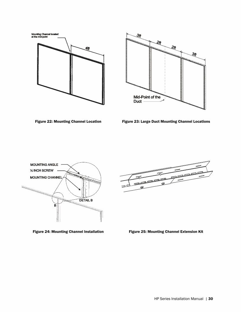
each additional mounting channel is placed at 4ft centers. In the figure below a typical 4ft x 8ft
installation is shown with the mounting angle surrounding the perimeter and a mounting
channel installed vertically at the center point of the duct.
In Figure 23: Large Duct Mounting Channel Locations, a 6ft high x 10ft wide mist eliminator
frame is shown. Notice how the mounting channel placement is offset from the center.
Installations between 8ft x 12ft to 16ft x 20ft may involve the removal of excess material.
Excess material is removed equally from both sides of the frame not from the middle.
To secure the mounting channel in place use the factory supplied ½ inch self-threading screws.
Use the center row of slotted holes to attach the mounting channel to the mounting angle.
Place one screw at the top and one at the bottom making sure that the mounting channel is
level or square to the ceiling, this will help for mounting the wire mesh. See Figure 24:
Mounting Channel Installation.
If the duct height greater than 8 feet a channel extension is needed in order to link 2 mounting
channels together. The extension slides inside the mounting channel. Use 4 ½ inch factory
supplied screws for each mounting channel as shown in Figure 25: Mounting Channel Extension
Kit.
Page 33
HP Series Installation Manual | 30
Figure 22: Mounting Channel Location
Figure 23: Large Duct Mounting Channel Locations
Figure 24: Mounting Channel Installation
Figure 25: Mounting Channel Extension Kit
Page 34
31 | HP Series Installation Manual
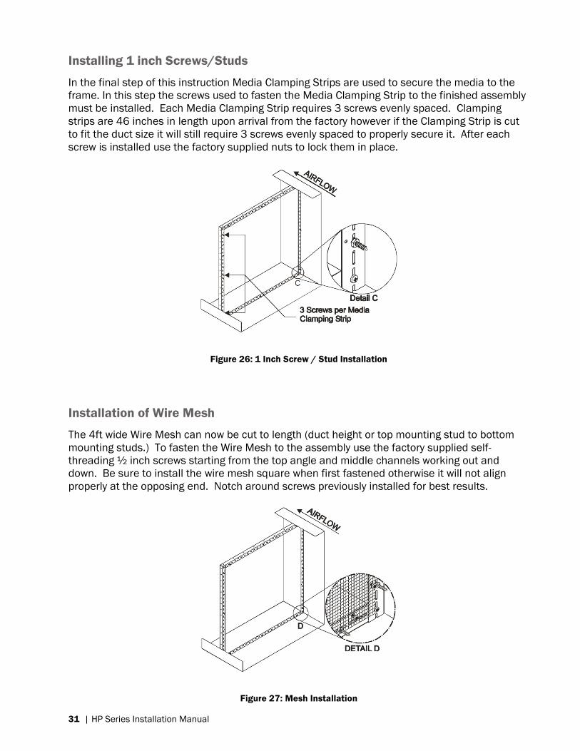
Installing 1 inch Screws/Studs
In the final step of this instruction Media Clamping Strips are used to secure the media to the
frame. In this step the screws used to fasten the Media Clamping Strip to the finished assembly
must be installed. Each Media Clamping Strip requires 3 screws evenly spaced. Clamping
strips are 46 inches in length upon arrival from the factory however if the Clamping Strip is cut
to fit the duct size it will still require 3 screws evenly spaced to properly secure it. After each
screw is installed use the factory supplied nuts to lock them in place.
Figure 26: 1 Inch Screw / Stud Installation
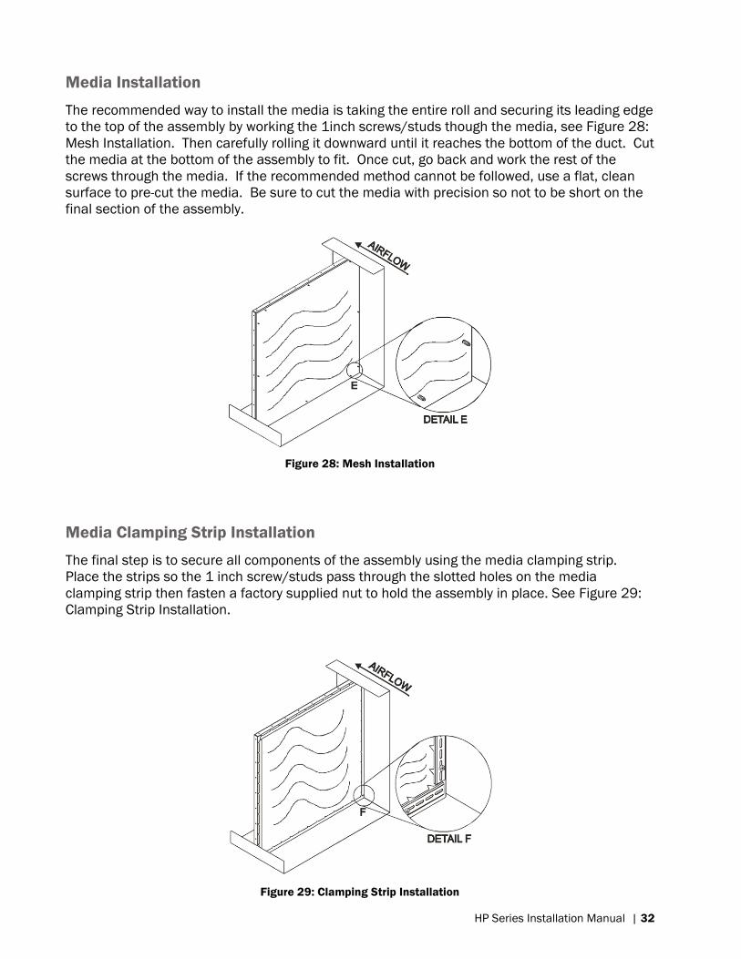
Installation of Wire Mesh
The 4ft wide Wire Mesh can now be cut to length (duct height or top mounting stud to bottom
mounting studs.) To fasten the Wire Mesh to the assembly use the factory supplied self-
threading ½ inch screws starting from the top angle and middle channels working out and
down. Be sure to install the wire mesh square when first fastened otherwise it will not align
properly at the opposing end. Notch around screws previously installed for best results.
Figure 27: Mesh Installation
Page 35
HP Series Installation Manual | 32
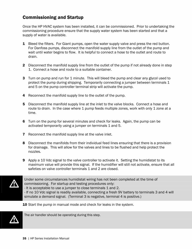
Media Installation
The recommended way to install the media is taking the entire roll and securing its leading edge
to the top of the assembly by working the 1inch screws/studs though the media, see Figure 28:
Mesh Installation. Then carefully rolling it downward until it reaches the bottom of the duct. Cut
the media at the bottom of the assembly to fit. Once cut, go back and work the rest of the
screws through the media. If the recommended method cannot be followed, use a flat, clean
surface to pre-cut the media. Be sure to cut the media with precision so not to be short on the
final section of the assembly.
Figure 28: Mesh Installation
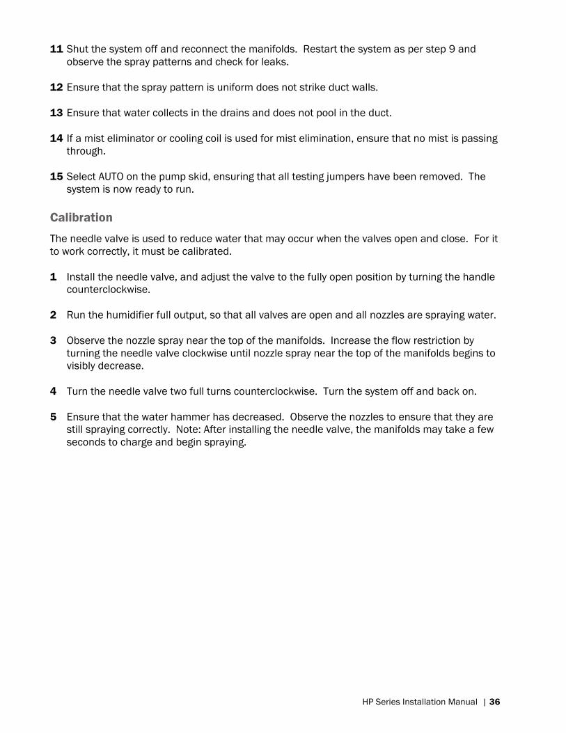
Media Clamping Strip Installation
The final step is to secure all components of the assembly using the media clamping strip.
Place the strips so the 1 inch screw/studs pass through the slotted holes on the media
clamping strip then fasten a factory supplied nut to hold the assembly in place. See Figure 29:
Clamping Strip Installation.
Figure 29: Clamping Strip Installation
Page 36
33 | HP Series Installation Manual
Page 37
HP Series Installation Manual | 34
Startup, Operation, & Maintenance
Page 38
35 | HP Series Installation Manual
Commissioning and Startup
Once the HP HVAC system has been installed, it can be commissioned. Prior to undertaking the
commissioning procedure ensure that the supply water system has been started and that a
supply of water is available.
1 Bleed the filters. For Giant pumps, open the water supply valve and press the red button.
For Danfoss pumps, disconnect the manifold supply line from the outlet of the pump and
wait until water begins to flow. It is helpful to connect a hose to the outlet and route to
drain.
2 Disconnect the manifold supply line from the outlet of the pump if not already done in step
1. Connect a hose and route to a suitable container.
3 Turn on pump and run for 1 minute. This will bleed the pump and clear any glycol used to
protect the pump during shipping. Temporarily connecting a jumper between terminals 1
and 5 on the pump controller terminal strip will activate the pump.
4 Reconnect the manifold supply line to the outlet of the pump.
5 Disconnect the manifold supply line at the inlet to the valve blocks. Connect a hose and
route to drain. In the case where 1 pump feeds multiple zones, work with only 1 zone at a
time.
6 Turn on the pump for several minutes and check for leaks. Again, the pump can be
activated temporarily using a jumper on terminals 1 and 5.
7 Reconnect the manifold supply line at the valve inlet.
8 Disconnect the manifolds from their individual feed lines ensuring that there is a provision
for drainage. This will allow for the valves and lines to be flushed and help protect the
nozzles.
9 Apply a 10 Vdc signal to the valve controller to activate it. Setting the humidistat to its
maximum value will provide this signal. If the humidifier will still not activate, ensure that all
safeties on valve controller terminals 1 and 2 are closed.
Under some circumstances humidistat wiring has not been completed at the time of
commissioning. For startup and testing procedures only:
- It is acceptable to use a jumper to close terminals 1 and 2.
- If no 10 Vdc signal is readily available, connecting a fresh 9V battery to terminals 3 and 4 will
simulate a demand signal. (Terminal 3 is negative, terminal 4 is positive.)
10 Start the pump in manual mode and check for leaks in the system.
The air handler should be operating during this step.
Page 39
HP Series Installation Manual | 36
11 Shut the system off and reconnect the manifolds. Restart the system as per step 9 and
observe the spray patterns and check for leaks.
12 Ensure that the spray pattern is uniform does not strike duct walls.
13 Ensure that water collects in the drains and does not pool in the duct.
14 If a mist eliminator or cooling coil is used for mist elimination, ensure that no mist is passing
through.
15 Select AUTO on the pump skid, ensuring that all testing jumpers have been removed. The
system is now ready to run.
Calibration
The needle valve is used to reduce water that may occur when the valves open and close. For it
to work correctly, it must be calibrated.
1 Install the needle valve, and adjust the valve to the fully open position by turning the handle
counterclockwise.
2 Run the humidifier full output, so that all valves are open and all nozzles are spraying water.
3 Observe the nozzle spray near the top of the manifolds. Increase the flow restriction by
turning the needle valve clockwise until nozzle spray near the top of the manifolds begins to
visibly decrease.
4 Turn the needle valve two full turns counterclockwise. Turn the system off and back on.
5 Ensure that the water hammer has decreased. Observe the nozzles to ensure that they are
still spraying correctly. Note: After installing the needle valve, the manifolds may take a few
seconds to charge and begin spraying.
Page 40
37 | HP Series Installation Manual
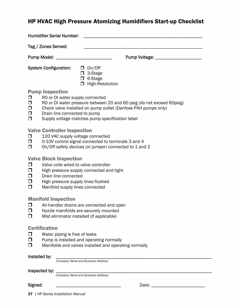
HP HVAC High Pressure Atomizing Humidifiers Start-up Checklist
Humidifier Serial Number: ___________________________________________________
Tag / Zones Served: ___________________________________________________
Pump Model: ________________________ Pump Voltage: ____________________
System Configuration: On/Off
3-Stage
6-Stage
High-Resolution
Pump Inspection RO or DI water supply connected
RO or DI water pressure between 20 and 60 psig (do not exceed 60psig)
Check valve installed on pump outlet (Danfoss PAH pumps only)
Drain line connected to pump
Supply voltage matches pump specification label
Valve Controller Inspection 120 VAC supply voltage connected
0-10V control signal connected to terminals 3 and 4
On/Off safety devices (or jumper) connected to 1 and 2
Valve Block Inspection Valve coils wired to valve controller
High pressure supply connected and tight
Drain line connected
High pressure supply lines flushed
Manifold supply lines connected
Manifold Inspection Air-handler drains are connected and open
Nozzle manifolds are securely mounted
Mist eliminator installed (if applicable)
Certification Water piping is free of leaks
Pump is installed and operating normally
Manifolds and valves installed and operating normally
Installed by: ___________________________________________________________________ (Company Name and Business Address)
Inspected by: ___________________________________________________________________ (Company Name and Business Address)
Signed: ____________________________ Date: _______________________
Page 41
HP Series Installation Manual | 38
Operation
When the humidification system has been installed and commissioned it will function as
follows:
1 The humidistat calls to the valve controller for humidity.
2 If On-Off Safety controls (air proving, high limit humidistat) are closed, the humidifier will
activate.
3 The pump module will activate and charge the lines to 1000psi.
4 The soft charge valves will open, softly charging the manifolds to prevent water hammer
effects.
5 The valve assembly will open valves as needed to provided water flow to the manifolds. The
manifolds will then spray water into the air stream, humidifying the air.
6 When the humidity targets have been met, the valve controller will close the valves and shut
off the pump, stopping the spray of water.
7 Water will drain from the manifolds to reduce the microbial growth that may occur in
standing water. An air break cap at the top of the manifolds will allow air to enter the lines
to facilitate this process.
8 Once every 24 hours, the valve controller will activate the system for 2 minutes to purge the
lines of any standing water. This process occurs regardless of demand for humidity at that
time.
Page 42
39 | HP Series Installation Manual
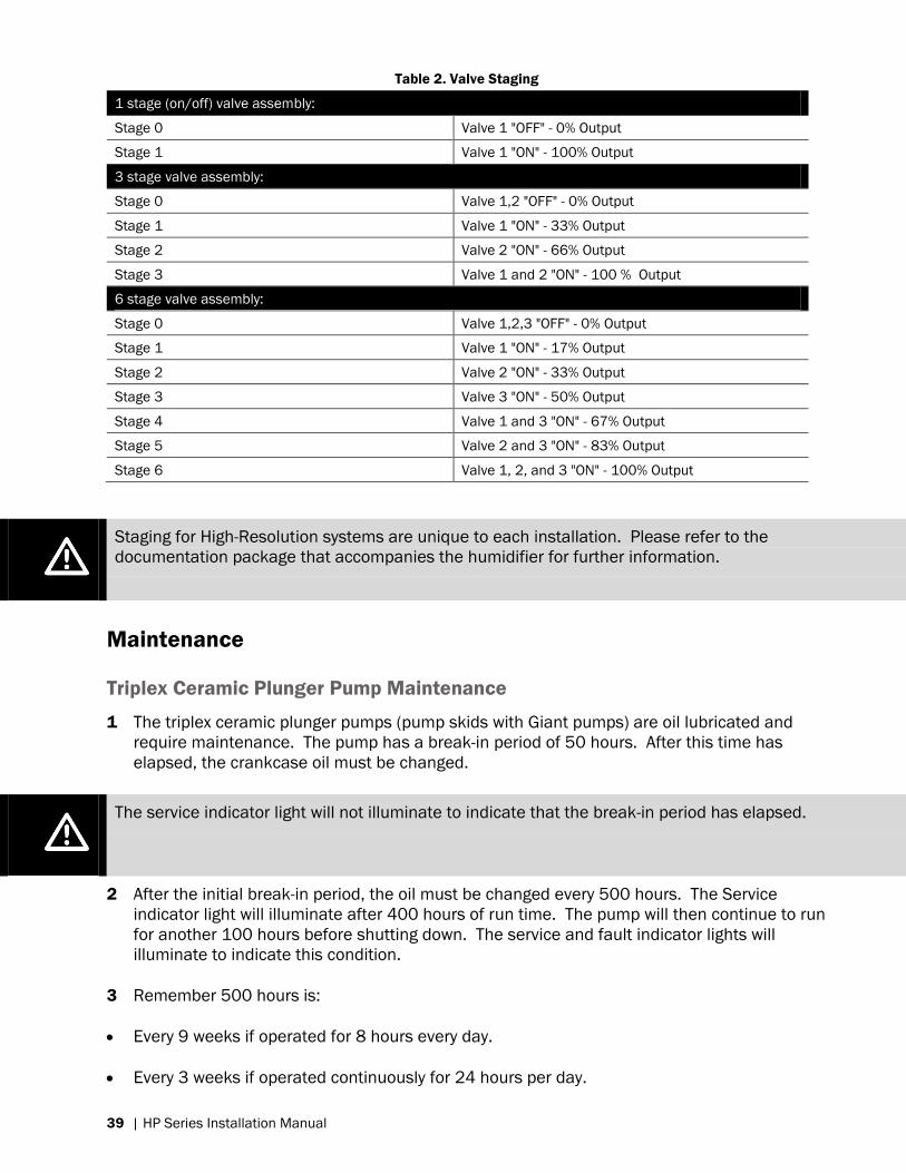
Table 2. Valve Staging
1 stage (on/off) valve assembly:
Stage 0 Valve 1 "OFF" - 0% Output
Stage 1 Valve 1 "ON" - 100% Output
3 stage valve assembly:
Stage 0 Valve 1,2 "OFF" - 0% Output
Stage 1 Valve 1 "ON" - 33% Output
Stage 2 Valve 2 "ON" - 66% Output
Stage 3 Valve 1 and 2 "ON" - 100 % Output
6 stage valve assembly:
Stage 0 Valve 1,2,3 "OFF" - 0% Output
Stage 1 Valve 1 "ON" - 17% Output
Stage 2 Valve 2 "ON" - 33% Output
Stage 3 Valve 3 "ON" - 50% Output
Stage 4 Valve 1 and 3 "ON" - 67% Output
Stage 5 Valve 2 and 3 "ON" - 83% Output
Stage 6 Valve 1, 2, and 3 "ON" - 100% Output
Staging for High-Resolution systems are unique to each installation. Please refer to the
documentation package that accompanies the humidifier for further information.
Maintenance
Triplex Ceramic Plunger Pump Maintenance
1 The triplex ceramic plunger pumps (pump skids with Giant pumps) are oil lubricated and
require maintenance. The pump has a break-in period of 50 hours. After this time has
elapsed, the crankcase oil must be changed.
The service indicator light will not illuminate to indicate that the break-in period has elapsed.
2 After the initial break-in period, the oil must be changed every 500 hours. The Service
indicator light will illuminate after 400 hours of run time. The pump will then continue to run
for another 100 hours before shutting down. The service and fault indicator lights will
illuminate to indicate this condition.
3 Remember 500 hours is:
Every 9 weeks if operated for 8 hours every day.
Every 3 weeks if operated continuously for 24 hours per day.
Page 43
HP Series Installation Manual | 40
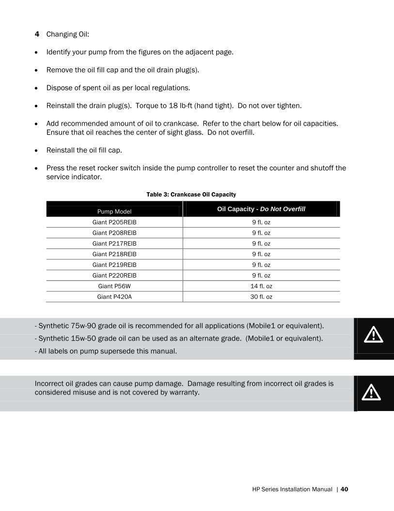
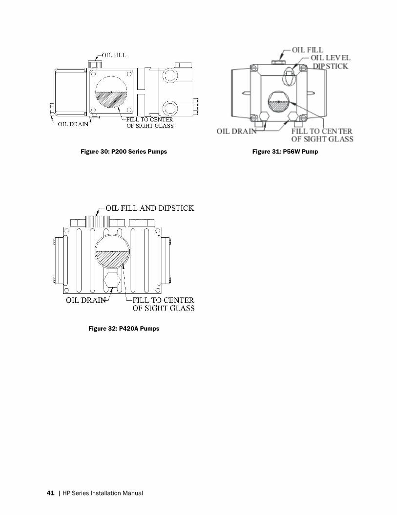
4 Changing Oil:
Identify your pump from the figures on the adjacent page.
Remove the oil fill cap and the oil drain plug(s).
Dispose of spent oil as per local regulations.
Reinstall the drain plug(s). Torque to 18 lb-ft (hand tight). Do not over tighten.
Add recommended amount of oil to crankcase. Refer to the chart below for oil capacities.
Ensure that oil reaches the center of sight glass. Do not overfill.
Reinstall the oil fill cap.
Press the reset rocker switch inside the pump controller to reset the counter and shutoff the
service indicator.
Table 3: Crankcase Oil Capacity
Pump Model Oil Capacity - Do Not Overfill
Giant P205REIB 9 fl. oz
Giant P208REIB 9 fl. oz
Giant P217REIB 9 fl. oz
Giant P218REIB 9 fl. oz
Giant P219REIB 9 fl. oz
Giant P220REIB 9 fl. oz
Giant P56W 14 fl. oz
Giant P420A 30 fl. oz
- Synthetic 75w-90 grade oil is recommended for all applications (Mobile1 or equivalent).
- Synthetic 15w-50 grade oil can be used as an alternate grade. (Mobile1 or equivalent).
- All labels on pump supersede this manual.
Incorrect oil grades can cause pump damage. Damage resulting from incorrect oil grades is
considered misuse and is not covered by warranty.
Page 44
41 | HP Series Installation Manual
Figure 30: P200 Series Pumps
Figure 32: P420A Pumps
Figure 31: P56W Pump
Page 45
HP Series Installation Manual | 42
Danfoss Stainless Steel Axial Piston Pump
1 The stainless steel axial piston pump is water lubricated and does not require any
maintenance. This pump has a lifespan of 8000 hours, after which time pump wear will
reduce its efficiency. If the pump is removed from service at 8000 hours it can usually be
rebuilt and receive another service life.
2 The service indicator light will illuminate after 7900 hours of operation. The pump will
continue to operate for another 100 hours after which time the service and fault indicators
will illuminate and the pump will shut down. Nortec recommends replacing the pump at this
time. Contact your local Nortec representative for further information.
3 After the pump head has been changed, press the reset switch inside the pump controller
housing to reset the service indicator and 8000 hour counter.
Resetting the counter without changing the pump head will allow the pump to be run to
destruction without further warning. Nortec strongly recommends against this, and cannot
offer warranty on downstream components damaged by pump debris resulting from pumps
run past 8000 hours.
Electrical Motor Service
1 Two types of electrical motors are used to drive the pumps; those with sealed rotor bearings
and those with external greased bearings. The sealed rotor bearing types are maintenance
free, while the external bearing types require periodic lubrication. Please refer to the
nameplate on the motor to identify which motor you have.
Table 4. Electrical Motor Service
Operation Service Interval
Standard (6 hours/day Every 3 years
Severe (18 hours/day) Every year
Seasonal (2000 hours per season) Beginning of each season
Table 5. Lubricant Volumes
Frame Size Relubrication Amounts
Volume cu. in. Fluid oz.
56 0.25 0.14
145 0.25 0.14
180 0.50 0.28
210 0.75 0.42
2 Electrical motors on the pump modules are pre-greased with a polyurea mineral oil NGLI
grade 2-type grease unless stated otherwise on the motor nameplate. Some compatible
brands of polyurea mineral base type grease are: Chevron SRI#2, Rykon Premium #2, Shell
Oil Doilum R, and Texaco Polystar RB. Motors are properly lubricated at time of manufacture
and do not need to be lubricated at the time of installation.
Page 46
43 | HP Series Installation Manual
Over greasing bearings can cause premature bearing and/or motor failure. The amount of grease
added to the motor should be carefully controlled.
Inlet Water Filters
The 10 micron water filters must be inspected periodically. Inspection is accomplished by
comparing the pressure valves on the filter inlet and outlet sides. When the pressure drop
across the filters reaches or exceeds 10 psi, the filters are considered spent and should be
replaced. The longevity of the filters depends entirely on the quality of the water being supplied
to the pump. Nortec recommends replacing the filters at a once per year as preventative
maintenance regardless of measured pressure drop.
Steps:
1 Turn the pump controller to off.
2 Turn the supply water valve to off.
3 Using a filter wrench, remove the filter housings.
4 Replace filter cartridges paying attention to any directional arrows.
5 Reinstall the filter housings, tighten hand tight with the filter wrench.
6 Turn the supply water back on.
7 Turn the power back on.
High and Low Pressure Lines and Hoses
The hoses and lines should be periodically inspected for damage, cracking, leaking. Ensure that
the pipes are rubbing on any vibrating equipment.
Atomization Nozzles
The Nortec HP HVAC system is designed to operate only on reverse osmosis or de-ionized water
supplies. This allows for long trouble free operation of the nozzles. Occasionally because of
either water quality or dirt, an atomization nozzle may become blocked. With the system
running, use a nozzle cleaning tool, or .007” (0.177mm) wire inside the nozzle orifice. Spin the
tool around until the blockage dislodges. If you are still unable to clear the blockage, contact
Nortec for a replacement nozzle.
Wear eye protection during this procedure.
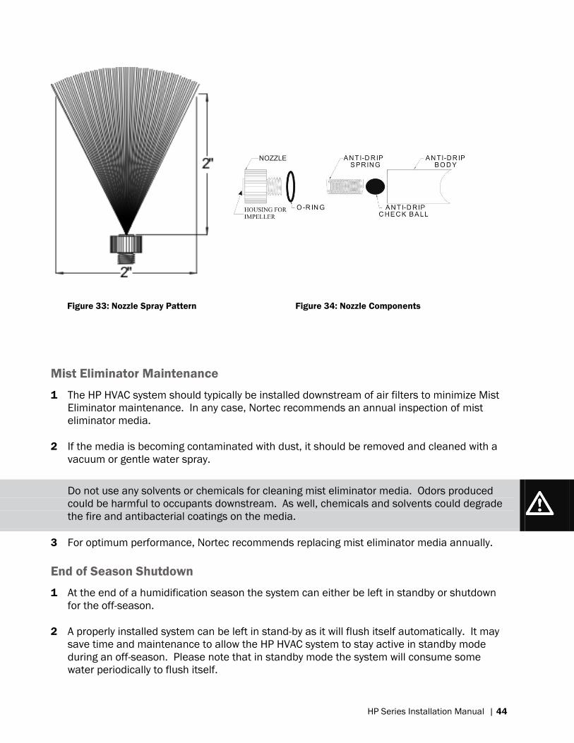
A proper spray pattern should be circular and measure 2” (50mm) across at a distance of 2”
(50mm) from the nozzle. See Figure 33 Nozzle Spray Pattern.
Please refer to Figure 34: Nozzle Components for assembly and disassembly of nozzle
components.
Page 47
HP Series Installation Manual | 44
Figure 33: Nozzle Spray Pattern
Figure 34: Nozzle Components
Mist Eliminator Maintenance
1 The HP HVAC system should typically be installed downstream of air filters to minimize Mist
Eliminator maintenance. In any case, Nortec recommends an annual inspection of mist
eliminator media.
2 If the media is becoming contaminated with dust, it should be removed and cleaned with a
vacuum or gentle water spray.
Do not use any solvents or chemicals for cleaning mist eliminator media. Odors produced
could be harmful to occupants downstream. As well, chemicals and solvents could degrade
the fire and antibacterial coatings on the media.
3 For optimum performance, Nortec recommends replacing mist eliminator media annually.
End of Season Shutdown
1 At the end of a humidification season the system can either be left in standby or shutdown
for the off-season.
2 A properly installed system can be left in stand-by as it will flush itself automatically. It may
save time and maintenance to allow the HP HVAC system to stay active in standby mode
during an off-season. Please note that in standby mode the system will consume some
water periodically to flush itself.
W
Page 48
45 | HP Series Installation Manual
3 The system can also be shut down for the off-season. If the system is to be shutdown for an
extended period of time, all automatic drain valves should be removed and the system
completely flushed. Then all water remaining in the lines should be air purged. The supply
water to the pump module should be turned off. Empty filter housings of any remaining
water and replace filter cartridges with new dry cartridges. Turn off electrical power to the
pump module. This will protect against corrosion and damage to the pump and lines.
Stainless steel pumps should not be inactive for more than 2 weeks without following the above
shutdown procedure.
Decommissioning / Freeze Protecting
If the system is to be decommissioned (shut-down for an extended period of time), or stored in a
cold area, the following procedure is applicable:
1 Disconnect the low pressure line at the inlet of the pump.
2 Connect the pump inlet to a canister containing a mixture of 35% glycol and water.
3 Disconnect the high pressure supply line at the inlet to the valve block.
4 Run the pump briefly to circulate the glycol mixture through the pump and supply lines.
5 Reconnect the high pressure supply lines to the valve block.
6 Disconnect the glycol canister and cap the pump inlet.
7 Decommission the RO system as per manufactures instructions (if applicable).
Inlet Water Pressure Switch
The inlet water pressure switch is hydraulically actuated, and completes a 24Vac control circuit.
The switch is rated to 150 psi, and cut off sensitivity is adjustable between 12 and 100 psi.
This switch is preset at 20 psi at the factory and does not require adjustment.
Page 49
Troubleshooting | 46
Troubleshooting
Page 50
47 | Troubleshooting
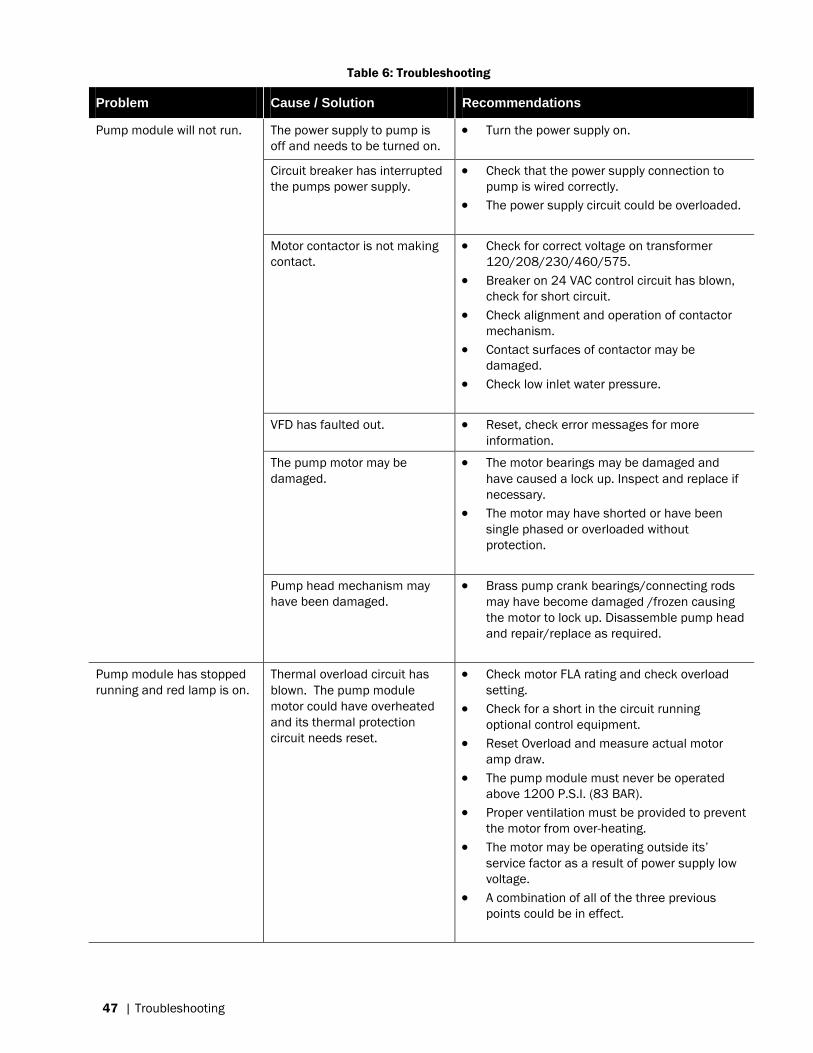
Table 6: Troubleshooting
Problem Cause / Solution Recommendations
Pump module will not run. The power supply to pump is
off and needs to be turned on.
Turn the power supply on.
Circuit breaker has interrupted
the pumps power supply.
Check that the power supply connection to
pump is wired correctly.
The power supply circuit could be overloaded.
Motor contactor is not making
contact.
Check for correct voltage on transformer
120/208/230/460/575.
Breaker on 24 VAC control circuit has blown,
check for short circuit.
Check alignment and operation of contactor
mechanism.
Contact surfaces of contactor may be
damaged.
Check low inlet water pressure.
VFD has faulted out. Reset, check error messages for more
information.
The pump motor may be
damaged.
The motor bearings may be damaged and
have caused a lock up. Inspect and replace if
necessary.
The motor may have shorted or have been
single phased or overloaded without
protection.
Pump head mechanism may
have been damaged.
Brass pump crank bearings/connecting rods
may have become damaged /frozen causing
the motor to lock up. Disassemble pump head
and repair/replace as required.
Pump module has stopped
running and red lamp is on.
Thermal overload circuit has
blown. The pump module
motor could have overheated
and its thermal protection
circuit needs reset.
Check motor FLA rating and check overload
setting.
Check for a short in the circuit running
optional control equipment.
Reset Overload and measure actual motor
amp draw.
The pump module must never be operated
above 1200 P.S.I. (83 BAR).
Proper ventilation must be provided to prevent
the motor from over-heating.
The motor may be operating outside its‟
service factor as a result of power supply low
voltage.
A combination of all of the three previous
points could be in effect.
Page 51
Troubleshooting | 48
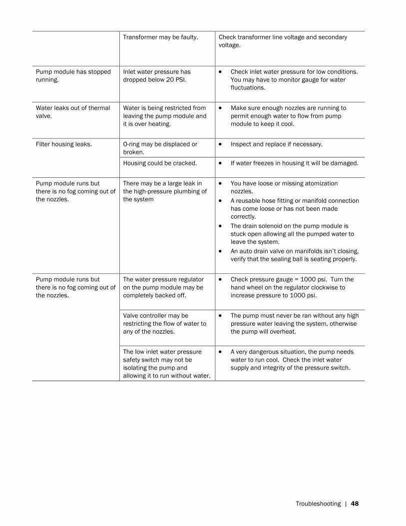
Transformer may be faulty. Check transformer line voltage and secondary
voltage.
Pump module has stopped
running.
Inlet water pressure has
dropped below 20 PSI.
Check inlet water pressure for low conditions.
You may have to monitor gauge for water
fluctuations.
Water leaks out of thermal
valve.
Water is being restricted from
leaving the pump module and
it is over heating.
Make sure enough nozzles are running to
permit enough water to flow from pump
module to keep it cool.
Filter housing leaks. O-ring may be displaced or
broken.
Inspect and replace if necessary.
Housing could be cracked. If water freezes in housing it will be damaged.
Pump module runs but
there is no fog coming out of
the nozzles.
There may be a large leak in
the high-pressure plumbing of
the system
You have loose or missing atomization
nozzles.
A reusable hose fitting or manifold connection
has come loose or has not been made
correctly.
The drain solenoid on the pump module is
stuck open allowing all the pumped water to
leave the system.
An auto drain valve on manifolds isn‟t closing,
verify that the sealing ball is seating properly.
Pump module runs but
there is no fog coming out of
the nozzles.
The water pressure regulator
on the pump module may be
completely backed off.
Check pressure gauge = 1000 psi. Turn the
hand wheel on the regulator clockwise to
increase pressure to 1000 psi.
Valve controller may be
restricting the flow of water to
any of the nozzles.
The pump must never be ran without any high
pressure water leaving the system, otherwise
the pump will overheat.
The low inlet water pressure
safety switch may not be
isolating the pump and
allowing it to run without water.
A very dangerous situation, the pump needs
water to run cool. Check the inlet water
supply and integrity of the pressure switch.
Page 52
49 | Troubleshooting
Page 53
Spare Parts | 50
Spare Parts
Page 54
51 | Spare Parts
5
6
7
3
12
14
13
4
Mo
tor s
ho
wn
he
re is
eq
uip
pe
d
with
a v
aria
ble
fre
que
nc
y d
rive
, w
hic
h is
an
op
tion.
2
This
pu
mp
ca
n e
ithe
r be
a s
tain
less
ste
el p
ump
(as
sho
wn)
or a
trip
lex
ce
ram
ic p
lung
er p
ump
.
89
10
11
15
1
Me
diu
m P
um
p M
odu
le S
pa
re P
arts
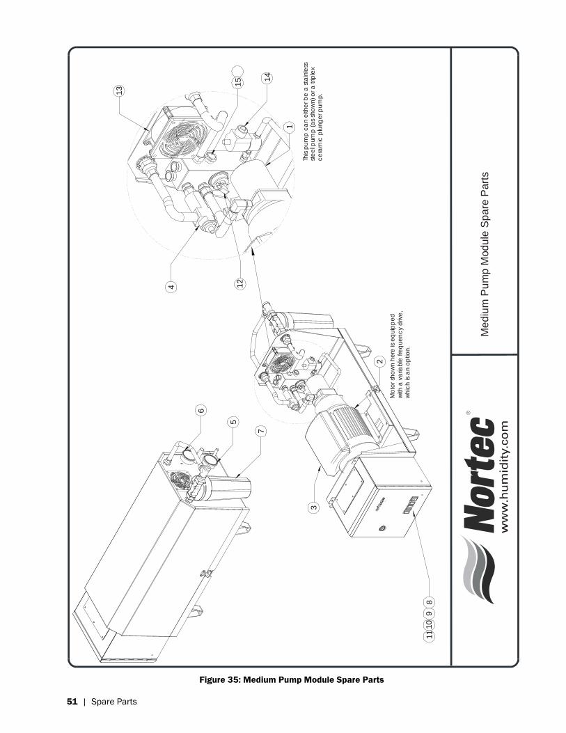
Figure 35: Medium Pump Module Spare Parts
Page 55
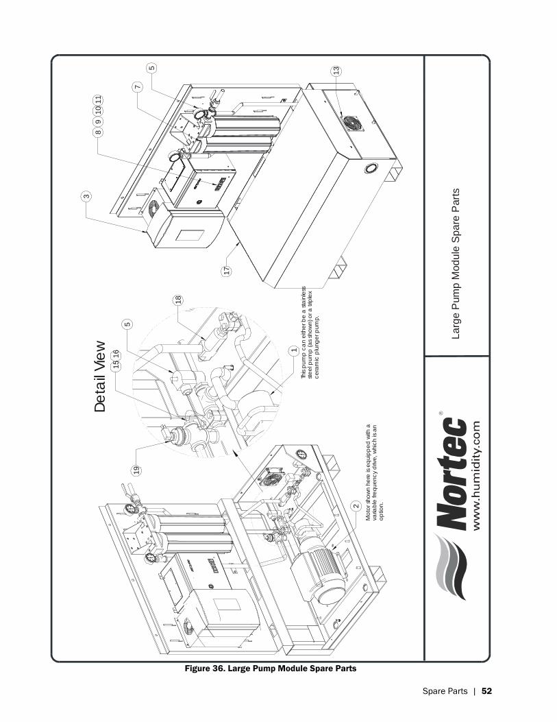
Spare Parts | 52
135
3
18
5
15
19
16
Mo
tor s
ho
wn h
ere
is e
quip
pe
d w
ith a
varia
ble
fre
que
nc
y d
rive, w
hic
h is
an
op
tion.
2
De
tail
Vie
w
This p
um
p c
an e
ithe
r be
a s
tain
less
ste
el p
um
p (a
s sh
ow
n) o
r a trip
lex
ce
ram
ic p
lung
er p
um
p.
1
89
10
11
17
7
La
rge
Pum
p M
odu
le S
pa
re P
arts
Figure 36. Large Pump Module Spare Parts
Page 56
53 | Spare Parts
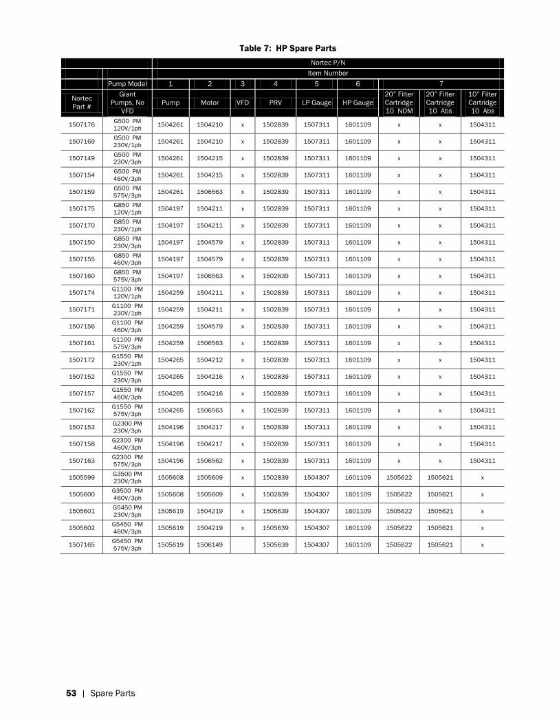
Table 7: HP Spare Parts
Nortec P/N
Item Number
Pump Model 1 2 3 4 5 6 7
Nortec
Part #
Giant
Pumps, No
VFD
Pump Motor VFD PRV LP Gauge HP Gauge
20” Filter
Cartridge
10 NOM
20” Filter
Cartridge
10 Abs
10” Filter
Cartridge
10 Abs
1507176 G500 PM
120V/1ph 1504261 1504210 x 1502839 1507311 1601109 x x 1504311
1507169 G500 PM
230V/1ph 1504261 1504210 x 1502839 1507311 1601109 x x 1504311
1507149 G500 PM
230V/3ph 1504261 1504215 x 1502839 1507311 1601109 x x 1504311
1507154 G500 PM
460V/3ph 1504261 1504215 x 1502839 1507311 1601109 x x 1504311
1507159 G500 PM
575V/3ph 1504261 1506563 x 1502839 1507311 1601109 x x 1504311
1507175 G850 PM
120V/1ph 1504197 1504211 x 1502839 1507311 1601109 x x 1504311
1507170 G850 PM
230V/1ph 1504197 1504211 x 1502839 1507311 1601109 x x 1504311
1507150 G850 PM
230V/3ph 1504197 1504579 x 1502839 1507311 1601109 x x 1504311
1507155 G850 PM
460V/3ph 1504197 1504579 x 1502839 1507311 1601109 x x 1504311
1507160 G850 PM
575V/3ph 1504197 1506563 x 1502839 1507311 1601109 x x 1504311
1507174 G1100 PM
120V/1ph 1504259 1504211 x 1502839 1507311 1601109 x x 1504311
1507171 G1100 PM
230V/1ph 1504259 1504211 x 1502839 1507311 1601109 x x 1504311
1507156 G1100 PM
460V/3ph 1504259 1504579 x 1502839 1507311 1601109 x x 1504311
1507161 G1100 PM
575V/3ph 1504259 1506563 x 1502839 1507311 1601109 x x 1504311
1507172 G1550 PM
230V/1ph 1504265 1504212 x 1502839 1507311 1601109 x x 1504311
1507152 G1550 PM
230V/3ph 1504265 1504216 x 1502839 1507311 1601109 x x 1504311
1507157 G1550 PM
460V/3ph 1504265 1504216 x 1502839 1507311 1601109 x x 1504311
1507162 G1550 PM
575V/3ph 1504265 1506563 x 1502839 1507311 1601109 x x 1504311
1507153 G2300 PM
230V/3ph 1504196 1504217 x 1502839 1507311 1601109 x x 1504311
1507158 G2300 PM
460V/3ph 1504196 1504217 x 1502839 1507311 1601109 x x 1504311
1507163 G2300 PM
575V/3ph 1504196 1506562 x 1502839 1507311 1601109 x x 1504311
1505599 G3500 PM
230V/3ph 1505608 1505609 x 1502839 1504307 1601109 1505622 1505621 x
1505600 G3500 PM
460V/3ph 1505608 1505609 x 1502839 1504307 1601109 1505622 1505621 x
1505601 G5450 PM
230V/3ph 1505619 1504219 x 1505639 1504307 1601109 1505622 1505621 x
1505602 G5450 PM
460V/3ph 1505619 1504219 x 1505639 1504307 1601109 1505622 1505621 x
1507165 G5450 PM
575V/3ph 1505619 1506149 1505639 1504307 1601109 1505622 1505621 x
Page 57
Spare Parts | 54
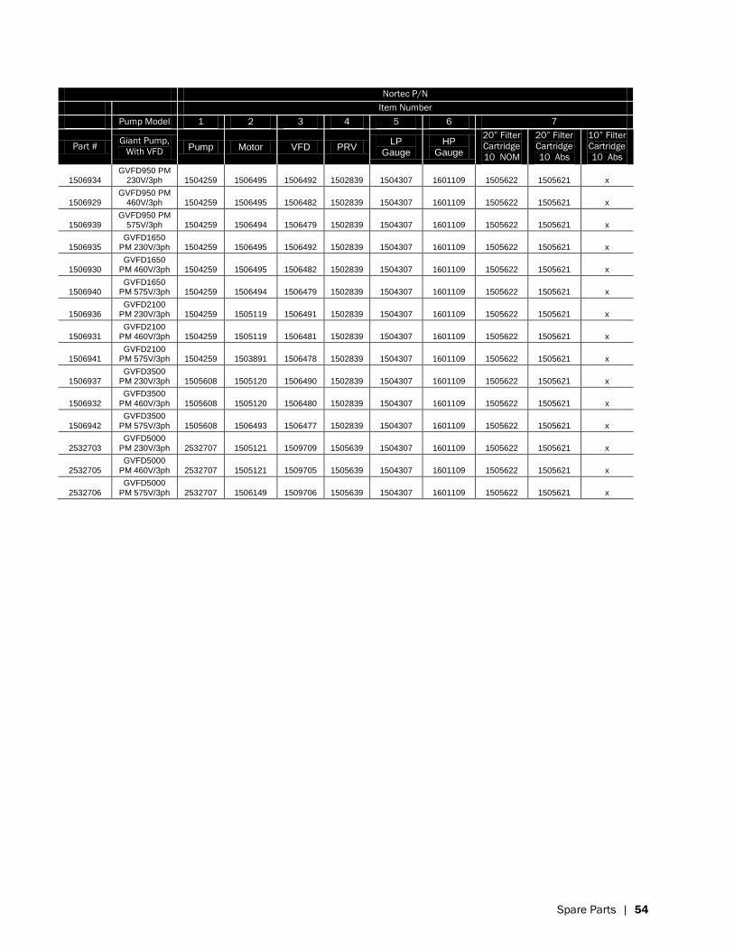
Nortec P/N
Item Number
Pump Model 1 2 3 4 5 6 7
Part # Giant Pump,
With VFD Pump Motor VFD PRV
LP Gauge
HP Gauge
20” Filter
Cartridge
10 NOM
20” Filter
Cartridge
10 Abs
10” Filter
Cartridge
10 Abs
1506934 GVFD950 PM
230V/3ph 1504259 1506495 1506492 1502839 1504307 1601109 1505622 1505621 x
1506929 GVFD950 PM
460V/3ph 1504259 1506495 1506482 1502839 1504307 1601109 1505622 1505621 x
1506939 GVFD950 PM
575V/3ph 1504259 1506494 1506479 1502839 1504307 1601109 1505622 1505621 x
1506935 GVFD1650
PM 230V/3ph 1504259 1506495 1506492 1502839 1504307 1601109 1505622 1505621 x
1506930 GVFD1650
PM 460V/3ph 1504259 1506495 1506482 1502839 1504307 1601109 1505622 1505621 x
1506940 GVFD1650
PM 575V/3ph 1504259 1506494 1506479 1502839 1504307 1601109 1505622 1505621 x
1506936 GVFD2100
PM 230V/3ph 1504259 1505119 1506491 1502839 1504307 1601109 1505622 1505621 x
1506931 GVFD2100
PM 460V/3ph 1504259 1505119 1506481 1502839 1504307 1601109 1505622 1505621 x
1506941 GVFD2100
PM 575V/3ph 1504259 1503891 1506478 1502839 1504307 1601109 1505622 1505621 x
1506937 GVFD3500
PM 230V/3ph 1505608 1505120 1506490 1502839 1504307 1601109 1505622 1505621 x
1506932 GVFD3500
PM 460V/3ph 1505608 1505120 1506480 1502839 1504307 1601109 1505622 1505621 x
1506942 GVFD3500
PM 575V/3ph 1505608 1506493 1506477 1502839 1504307 1601109 1505622 1505621 x
2532703 GVFD5000
PM 230V/3ph 2532707 1505121 1509709 1505639 1504307 1601109 1505622 1505621 x
2532705 GVFD5000
PM 460V/3ph 2532707 1505121 1509705 1505639 1504307 1601109 1505622 1505621 x
2532706 GVFD5000
PM 575V/3ph 2532707 1506149 1509706 1505639 1504307 1601109 1505622 1505621 x
Page 58
55 | Spare Parts
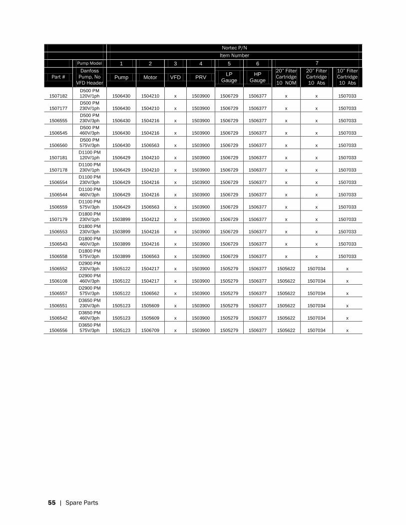
Nortec P/N
Item Number
Pump Model 1 2 3 4 5 6 7
Part #
Danfoss
Pump, No
VFD Header Pump Motor VFD PRV
LP Gauge
HP Gauge
20” Filter
Cartridge
10 NOM
20” Filter
Cartridge
10 Abs
10” Filter
Cartridge
10 Abs
1507182 D500 PM 120V/1ph 1506430 1504210 x 1503900 1506729 1506377 x x 1507033
1507177 D500 PM 230V/1ph 1506430 1504210 x 1503900 1506729 1506377 x x 1507033
1506555 D500 PM 230V/3ph 1506430 1504216 x 1503900 1506729 1506377 x x 1507033
1506545 D500 PM 460V/3ph 1506430 1504216 x 1503900 1506729 1506377 x x 1507033
1506560 D500 PM 575V/3ph 1506430 1506563 x 1503900 1506729 1506377 x x 1507033
1507181 D1100 PM 120V/1ph 1506429 1504210 x 1503900 1506729 1506377 x x 1507033
1507178 D1100 PM 230V/1ph 1506429 1504210 x 1503900 1506729 1506377 x x 1507033
1506554 D1100 PM 230V/3ph 1506429 1504216 x 1503900 1506729 1506377 x x 1507033
1506544 D1100 PM 460V/3ph 1506429 1504216 x 1503900 1506729 1506377 x x 1507033
1506559 D1100 PM 575V/3ph 1506429 1506563 x 1503900 1506729 1506377 x x 1507033
1507179 D1800 PM 230V/1ph 1503899 1504212 x 1503900 1506729 1506377 x x 1507033
1506553 D1800 PM 230V/3ph 1503899 1504216 x 1503900 1506729 1506377 x x 1507033
1506543 D1800 PM 460V/3ph 1503899 1504216 x 1503900 1506729 1506377 x x 1507033
1506558 D1800 PM 575V/3ph 1503899 1506563 x 1503900 1506729 1506377 x x 1507033
1506552 D2900 PM 230V/3ph 1505122 1504217 x 1503900 1505279 1506377 1505622 1507034 x
1506108 D2900 PM 460V/3ph 1505122 1504217 x 1503900 1505279 1506377 1505622 1507034 x
1506557 D2900 PM 575V/3ph 1505122 1506562 x 1503900 1505279 1506377 1505622 1507034 x
1506551 D3650 PM 230V/3ph 1505123 1505609 x 1503900 1505279 1506377 1505622 1507034 x
1506542 D3650 PM 460V/3ph 1505123 1505609 x 1503900 1505279 1506377 1505622 1507034 x
1506556 D3650 PM 575V/3ph 1505123 1506709 x 1503900 1505279 1506377 1505622 1507034 x
Page 59
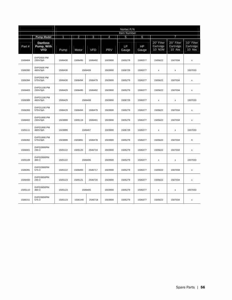
Spare Parts | 56
Nortec P/N
Item Number
Pump Model 1 2 3 4 5 6 7
Part # Danfoss
Pump, With VFD Pump Motor VFD PRV
LP Gauge
HP Gauge
20” Filter
Cartridge
10 NOM
20” Filter
Cartridge
10 Abs
10” Filter
Cartridge
10 Abs
1506404 DVFD500 PM 230V/3ph 1506430 1506495 1506492 1503900 1505279 1506377 1505622 1507034 x
1506390 DVFD500 PM 460V/3ph 1506430 1506409 1503900 1506729 1506377 x x 1507033
1506394 DVFD500 PM 575V/3ph 1506430 1506494 1506479 1503900 1505279 1506377 1505622 1507034 x
1506403 DVFD1100 PM 230V/3ph 1506429 1506495 1506492 1503900 1505279 1506377 1505622 1507034 x
1506389 DVFD1100 PM 460V/3ph 1506429 1506408 1503900 1506729 1506377 x x 1507033
1506393 DVFD1100 PM 575V/3ph 1506429 1506494 1506479 1503900 1505279 1506377 1505622 1507034 x
1506402 DVFD1800 PM 230V/3ph 1503899 1505119 1506491 1503900 1505279 1506377 1505622 1507034 x
1505111 DVFD1800 PM 460V/3ph 1503899 1506407 1503900 1506729 1506377 x x 1507033
1506392 DVFD1800 PM 575V/3ph 1503899 1503891 1506478 1503900 1505279 1506377 1505622 1507034 X
1506401 DVFD2900PM 230-3 1505122 1505120 2546719 1503900 1505279 1506377 1505622 1507034 x
1505109 DVFD2900PM 460-3 1505122 1506406 1503900 1505279 1506377 x x 1507033
1506391 DVFD2900PM 575-3 1505122 1506493 2546717 1503900 1505279 1506377 1505622 1507034 x
1506400 DVFD3650PM 230-3 1505123 1505121 2546720 1503900 1505279 1506377 1505622 1507034 x
1505110 DVFD3650PM 460-3 1505123 1506405 1503900 1505279 1506377 x x 1507033
1506151 DVFD3650PM 575-3 1505123 1506149 2546718 1503900 1505279 1506377 1505622 1507034 x
Page 60
57 | Spare Parts
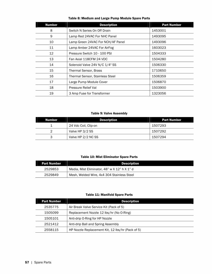
Table 8: Medium and Large Pump Module Spare Parts
Number Description Part Number
8 Switch N Series On Off Drain 1453001
9 Lamp Red 24VAC For NHC Panel 1493095
10 Lamp Green 24VAC For NCH/AF Panel 1493096
11 Lamp Amber 24VAC For AirFog 1603023
12 Pressure Switch 10 - 100 PSI 1504333
13 Fan Axial 118CFM 24 VDC 1504280
14 Solenoid Valve 24V N/C 1/4" SS 1506330
15 Thermal Sensor, Brass 1710650
16 Thermal Sensor, Stainless Steel 1506359
17 Large Pump Module Cover 1506870
18 Pressure Relief Val 1503900
19 3 Amp Fuse for Transformer 1323056
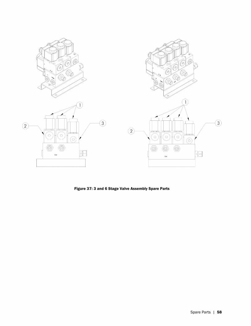
Table 9: Valve Assembly
Number Description Part Number
1 24 Vdc Coil, Clip-on 1507293
2 Valve HP 3/2 SS 1507292
3 Valve HP 2/2 NC SS 1507294
Table 10: Mist Eliminator Spare Parts
Part Number Description
2529853 Media, Mist Eliminator, 48” w X 12” h X 1” d
2529849 Mesh, Welded Wire, 4x4 304 Stainless Steel
Table 11: Manifold Spare Parts
Part Number Description
2535775 Air Break Valve Service Kit (Pack of 5)
1505099 Replacement Nozzle 12 lbs/hr (No O-Ring)
1505101 Anti-drip O-Ring for HP Nozzle
2521412 Anti-drip Ball and Spring Assembly
2558115 HP Nozzle Replacement Kit, 12 lbs/hr (Pack of 5)
Page 61
Spare Parts | 58
Figure 37: 3 and 6 Stage Valve Assembly Spare Parts
Page 63
Wiring Diagrams | 60
Wiring & Installation Diagrams
Page 64
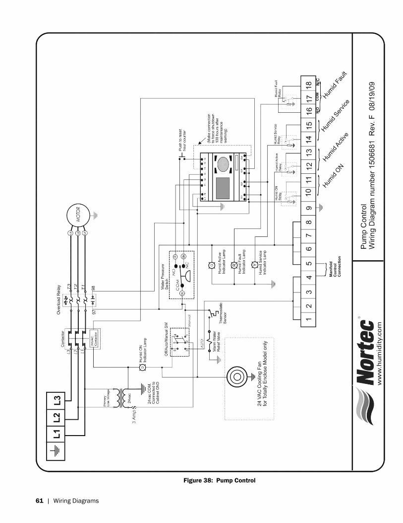
61 | Wiring Diagrams
Figure 38: Pump Control
Page 65
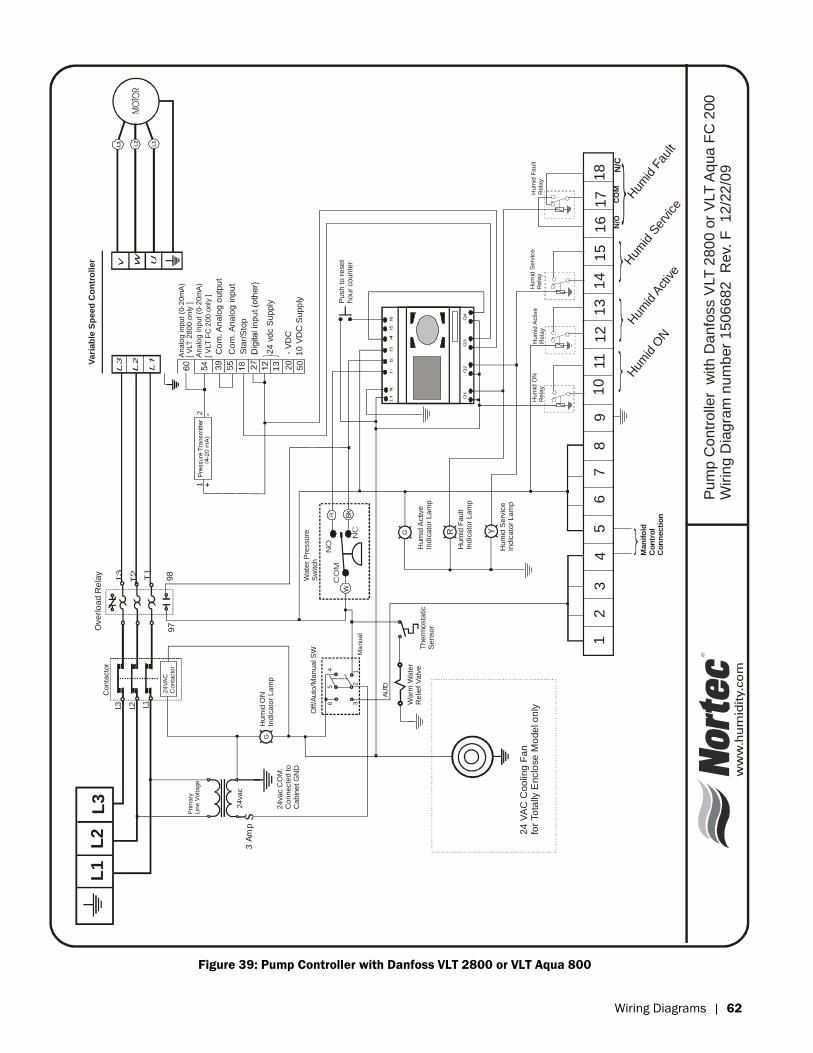
Wiring Diagrams | 62
L1L2L3
24
VA
CC
on
tacto
r
3 A
mps
L1
L2
L3
L1
L2
L3
Vari
ab
le S
peed
Co
ntr
oller
AUTO
Ma
nua
l
Off
/Au
to/M
an
ua
l S
W
G
G
Hu
mid
ON
Ind
ica
tor
La
mp
12
34
56
78
91
011
12
13
14
15
16
17
18
Y
C
om
. A
nalo
g o
utp
ut
C
om
. A
nalo
g inpu
t
S
tar/
Sto
p
12 -
+
Overlo
ad R
ela
yC
on
tacto
r
Hum
id A
ctive
Ind
ica
tor
La
mp
Hu
mid
Serv
ice
Ind
ica
tor
La
mp
24
va
c
24
va
c C
OM
.C
onn
ecte
d t
oC
abin
et
GN
D
Prim
ary
Lin
e V
oltag
e
Wa
ter
Pre
ssu
reS
witch
Th
erm
osta
tic
Se
nso
r
Wa
rm W
ate
rR
elie
f V
alv
e
Pu
mp C
on
trolle
r w
ith
Da
nfo
ss V
LT
28
00
or
VLT
Aq
ua
FC
200
W
irin
g D
iag
ram
nu
mb
er
15
06
68
2
Rev.
F
12
/22
/09
R
Hu
mid
Fa
ult
Ind
ica
tor
La
mp
- V
DC
10
VD
C S
upp
ly
31
56
4
2
Push
to
re
se
t h
ou
r co
un
ter
55
13 20
50
Ana
log in
pu
t (0
-20m
A)
24 v
dc S
upply
24
VA
C C
oo
ling
Fa
nfo
r To
tally
Enclo
se
Mo
de
l o
nly
Man
ifo
ldC
on
tro
l C
on
necti
on
Hum
id S
ervice
Hum
id F
ault
Hum
id A
ctive
Hum
id O
N
CO
MN
/ON
/C
Hum
id O
NR
ela
yH
um
id A
ctive
Rela
y
Hum
id S
erv
ice
Rela
yH
um
id F
au
ltR
ela
y
97
98
[ V
LT
28
00
on
ly ]
[ V
LT
FC
200
only
]
Ana
log in
pu
t (0
-20m
A)
Figure 39: Pump Controller with Danfoss VLT 2800 or VLT Aqua 800
Page 66
63 | Wiring Diagrams
Figure 40: Pump Controller with Danfoss Integrated VFD
Page 67
Wiring Diagrams | 64
Figure 41: 1 Stage Valve Controller
Page 68
65 | Wiring Diagrams
Figure 42: 3 Stage Valve Controller
Page 69
Wiring Diagrams | 66
Figure 43: 6 Stage Valve Controller
Page 70
67 | Wiring Diagrams
HP HVACSoft Charge Valve Assembly - 1 StagePart #1506715April 25, 2010
4.5 in.( 114 mm )
6.6 in.( 168 mm )
8.0 in.( 203 mm )
3.1 in.( 80 mm )
8.4 in.( 214 mm )
3.2 in.( 80 mm )
2.6 in.( 66 mm )
0.6 in.( 15 mm )
6.0 in.( 152 mm )
8.0 in.( 203 mm )
4.0 in.( 102 mm )
1.4 in.( 34 mm )
2.3 in.( 57 mm )
3.2 in.( 80 mm )
4.0 in.( 100 mm )
8.4 in.( 214 mm )
6.0 in.( 152 mm )
3.6 in.( 92 mm )
1.5 in.( 39 mm )
3.0 in.( 75 mm )
6.8 in.( 171 mm)
O 0.4 in.( 10 mm )
Voltage: 24VDCPower: 18 W per coil, 3 coils totalInlet Connection: ½” compression fittingDrain Connection: ½” compression fittingManifold Connection: 3/8” compression fitting Max. Pressure: 2000 psig (138 bar)Min. Flow: 0.3 gpm (1 Lpm)Max. Flow: 7.9 gpm (30 Lpm) Pressure Loss: 36 psig @ max flow (2.5 bar)Weight: 16 lbs (7 kg)Material: 304 stainless steel and plastic
Figure 44: HP HVAC Soft Charge Valve Assembly – 1 Stage
Page 71
Wiring Diagrams | 68
HP HVACSoft Charge Valve Assembly - 3 StagePart #150 6714April 26, 2010
1/2" Compression
3/8" Compression
4.5 in.( 114 mm )
6.6 in.( 168 mm )
2.1 in.( 55 mm )
4.1 in.( 105 mm )
2.6 in.( 66 mm )
8.0 in.( 203 mm )
6.0 in.( 152 mm )
2.3 in.( 57 mm )
3.2 in.( 80 mm )
1.4 in.( 34 mm )
4.0 in.( 100 mm )
6.0 in.( 152 mm )
8.4 in.( 214 mm )
O 0.4 in.( 10 mm )
2.3 in.( 57 mm )
1.5 in.( 39 mm )
3.6 in.( 92 mm )
1.5 in.( 39 mm )
3.0 in.( 75 mm )
6.8 in.( 171 mm)
Voltage: 24VDCPower: 18 W per coil, 5 coils totalInlet Connection: ½” compression fittingDrain Connection: ½” compression fittingManifold Connection: 3/8” compression fitting Max. Pressure: 2000 psig (138 bar)Min. Flow: 0.3 gpm (1 Lpm)Max. Flow: 7.9 gpm (30 Lpm) Pressure Loss: 36 psig @ max flow (2.5 bar)Weight: 28 lbs (13 kg)Material: 304 stainless steel and plastic
Figure 45: HP HVAC Soft Charge Valve Assembly – 3 Stage
Page 72
69 | Wiring Diagrams
HP HVACSoft Charge Valve Assembly - 6 StagePart #1506713April 26, 2010
3/8" Compression
1/2" Compression
6.8 in.( 171 mm)
3.6 in.( 92 mm )
4.5 in.( 114 mm )
0.9 in.( 24 mm )
2.9 in.( 74 mm )
4.9 in.( 123 mm )
O 0.4 in.( 10 mm )
6.6 in.( 168 mm )
1.5 in.( 39 mm )
3.0 in.( 75 mm )
1.5 in.( 39 mm )
2.3 in.( 57 mm )
2.6 in.( 66 mm )
8.0 in.( 203 mm )
8.0 in.( 202 mm )
2.3 in.( 57 mm )1.4 in.
( 34 mm )
3.2 in.( 80 mm )
4.0 in.( 100 mm )
6.0 in.( 152 mm )
8.4 in.( 214 mm )
Voltage: 24VDCPower: 18 W per coil, 7 coils totalInlet Connection: ½” compression fittingDrain Connection: ½” compression fittingManifold Connection: 3/8” compression fitting Max. Pressure: 2000 psig (138 bar)Min. Flow: 0.3 gpm (1 Lpm)Max. Flow: 7.9 gpm (30 Lpm) Pressure Loss: 36 psig @ max flow (2.5 bar)Weight: 38 lbs (17kg)Material: 304 stainless steel and plastic
Figure 46: HP HVAC Soft Charge Valve Assembly – 6 Stage
Page 73
Wiring Diagrams | 70
Figure 47: HP Valve Controller
April 9, 2010
Page 74
71 | Wiring Diagrams
Page 75
Warranty
Nortec Humidity Inc. and/or Nortec Humidity Ltd. (hereinafter collectively referred to as THE COMPANY), warrant for a period of two years after installation or 30 months from manufacturer’s ship date, whichever date is earlier, that THE COMPANY’s manufactured and assembled products, not otherwise expressly warranted, are free from defects in material and workmanship. No warranty is made against corrosion, deterioration, or suitability of substituted materials used as a result of compliance with government regulations.
THE COMPANY’s obligations and liabilities under this warranty are limited to furnishing replacement parts to the customer, F.O.B. THE COMPANY’s factory, providing the defective part(s) is returned freight prepaid by the customer. Parts used for repairs are warranted for the balance of the term of the warranty on the original humidifier or 90 days, whichever is longer.
The warranties set forth herein are in lieu of all other warranties expressed or implied by law. No liability whatsoever shall be attached to THE COMPANY until said products have been paid for in full and then said liability shall be limited to the original purchase price for the product. Any further warranty must be in writing, signed by an officer of THE COMPANY.
THE COMPANY’s limited warranty on accessories, not of the companies manufacture, such as controls, humidistats, pumps, etc. is limited to the warranty of the original equipment manufacturer from date of original shipment of humidifier.
THE COMPANY makes no warranty and assumes no liability unless the equipment is installed in strict accordance with a copy of the catalog and installation manual in effect at the date of purchase and by a contractor approved by THE COMPANY to install such equipment.
THE COMPANY makes no warranty and assumes no liability whatsoever for consequential damage or damage resulting directly from misapplication, incorrect sizing or lack of proper maintenance of the equipment.
THE COMPANY makes no warranty and assumes no liability whatsoever for damage resulting from freezing of the humidifier, supply lines, drain lines, or steam distribution systems.
THE COMPANY retains the right to change the design, specification and performance criteria of its products without notice or obligation.
Page 76
U.S.A. 1860 Renaissance Blvd. Sturtevant, WI 53177
826 Proctor Avenue Ogdensburg, NY 13669
CANADA 2740 Fenton Road Ottawa, Ontario K1T 3T7
TEL: 1.866.NORTEC1 EMAIL: [email protected] WEBSITE: www.humidity.com