171
HP StorageWorks 4000/6000/8000 Enterprise Virtual Array user guide Part number: 5697–5415 Second edition: September 2005

HP StorageWorks
4000/6000/8000 Enterprise Virtual Arrayuser guide
Part number: 5697–5415Second edition: September 2005

Legal and notice information
© Copyright 2005 Hewlett-Packard Development Company, L.P.
Hewlett-Packard Company makes no warranty of any kind with regard to this material, including, but not limited to, the impliedwarranties of merchantability and fitness for a particular purpose. Hewlett-Packard shall not be liable for errors contained herein orfor incidental or consequential damages in connection with the furnishing, performance, or use of this material.
This document contains proprietary information, which is protected by copyright. No part of this document may be photocopied,reproduced, or translated into another language without the prior written consent of Hewlett-Packard. The information is provided“as is” without warranty of any kind and is subject to change without notice. The only warranties for HP products and services areset forth in the express warranty statements accompanying such products and services. Nothing herein should be construed asconstituting an additional warranty. HP shall not be liable for technical or editorial errors or omissions contained herein.
Microsoft®, MS-DOS®, MS Windows®, Windows®, Windows NT®, and Windows Server® are U.S. registered trademarks ofMicrosoft Corporation.
UNIX® is a registered trademark of The Open Group.
Java™ and Solaris™ are trademarks of Sun Microsystems, Inc.
Red Hat® and Red Hat® Enterprise Linux are registered trademarks of Red Hat, Inc.
Linux® is a registered trademark of Linus Torvalds.
Hewlett-Packard Company shall not be liable for technical or editorial errors or omissions contained herein. The information isprovided “as is” without warranty of any kind and is subject to change without notice. The warranties for Hewlett-Packard Companyproducts are set forth in the express limited warranty statements for such products. Nothing herein should be construed asconstituting an additional warranty.
4000/6000/8000 Enterprise Virtual Array user guide
Contents
About this guide . . . . . . . . . . . . . . . . . . . . . . . . . 13Overview . . . . . . . . . . . . . . . . . . . . . . . . . . . . . . . . . . . . . . . . . 13
Intended audience . . . . . . . . . . . . . . . . . . . . . . . . . . . . . . . . . . . 13Related documentation . . . . . . . . . . . . . . . . . . . . . . . . . . . . . . . . . 13
Document conventions and symbols . . . . . . . . . . . . . . . . . . . . . . . . . . . . . 14Rack stability . . . . . . . . . . . . . . . . . . . . . . . . . . . . . . . . . . . . . . . 15HP technical support . . . . . . . . . . . . . . . . . . . . . . . . . . . . . . . . . . . . 15
HP-authorized reseller . . . . . . . . . . . . . . . . . . . . . . . . . . . . . . . . . 15Helpful web sites . . . . . . . . . . . . . . . . . . . . . . . . . . . . . . . . . . . 15
1 Enterprise Virtual Array description . . . . . . . . . . . . . . . . . 17Introduction to the Enterprise Virtual Array . . . . . . . . . . . . . . . . . . . . . . . . . . . 17Features and enhancements . . . . . . . . . . . . . . . . . . . . . . . . . . . . . . . . . 17
Ease of management . . . . . . . . . . . . . . . . . . . . . . . . . . . . . . . . . . 18Data availability . . . . . . . . . . . . . . . . . . . . . . . . . . . . . . . . . . . . 18Performance . . . . . . . . . . . . . . . . . . . . . . . . . . . . . . . . . . . . . 18Scalability . . . . . . . . . . . . . . . . . . . . . . . . . . . . . . . . . . . . . . 18Operating system support . . . . . . . . . . . . . . . . . . . . . . . . . . . . . . . . 19Fault management and diagnostics . . . . . . . . . . . . . . . . . . . . . . . . . . . . 19EVA remote support tools . . . . . . . . . . . . . . . . . . . . . . . . . . . . . . . . 19
Storage system components . . . . . . . . . . . . . . . . . . . . . . . . . . . . . . . . . 19HP Command View EVA . . . . . . . . . . . . . . . . . . . . . . . . . . . . . . . . 20Controller software . . . . . . . . . . . . . . . . . . . . . . . . . . . . . . . . . . . 20
XCS features and functionality . . . . . . . . . . . . . . . . . . . . . . . . . . . . 20Optional software licensing . . . . . . . . . . . . . . . . . . . . . . . . . . . . . 20
Hardware . . . . . . . . . . . . . . . . . . . . . . . . . . . . . . . . . . . . . . 21Physical layout of the storage system . . . . . . . . . . . . . . . . . . . . . . . . . 21Fibre Channel drive enclosure . . . . . . . . . . . . . . . . . . . . . . . . . . . . 21Fibre Channel loop switches . . . . . . . . . . . . . . . . . . . . . . . . . . . . . 22HSV210 and HSV200 controllers . . . . . . . . . . . . . . . . . . . . . . . . . . 22Racks . . . . . . . . . . . . . . . . . . . . . . . . . . . . . . . . . . . . . . 22
2 Enterprise Virtual Array startup . . . . . . . . . . . . . . . . . . 25EVA8000 storage system connections . . . . . . . . . . . . . . . . . . . . . . . . . . . . . 25EVA6000 storage system connections . . . . . . . . . . . . . . . . . . . . . . . . . . . . . 26EVA4000 storage system connections . . . . . . . . . . . . . . . . . . . . . . . . . . . . . 27Direct connect . . . . . . . . . . . . . . . . . . . . . . . . . . . . . . . . . . . . . . . 28Procedures for getting started . . . . . . . . . . . . . . . . . . . . . . . . . . . . . . . . 28
Gathering information . . . . . . . . . . . . . . . . . . . . . . . . . . . . . . . . . 28Host information . . . . . . . . . . . . . . . . . . . . . . . . . . . . . . . . . . 29
Setting up a controller pair using the OCP . . . . . . . . . . . . . . . . . . . . . . . . . 29Entering the WWN . . . . . . . . . . . . . . . . . . . . . . . . . . . . . . . . 29Entering the WWN checksum . . . . . . . . . . . . . . . . . . . . . . . . . . . . 30Entering the storage system password . . . . . . . . . . . . . . . . . . . . . . . . . 31
Installing HP Command View EVA . . . . . . . . . . . . . . . . . . . . . . . . . . . . 31Installing optional EVA software licenses . . . . . . . . . . . . . . . . . . . . . . . . . 31
3 Enterprise Virtual Array operation . . . . . . . . . . . . . . . . . 33Best practices . . . . . . . . . . . . . . . . . . . . . . . . . . . . . . . . . . . . . . . 33
4000/6000/8000 Enterprise Virtual Array user guide 3

Operating tips and information . . . . . . . . . . . . . . . . . . . . . . . . . . . . . . . 33Reserving adequate free space . . . . . . . . . . . . . . . . . . . . . . . . . . . . . 33
Failback preference setting for HSV controllers . . . . . . . . . . . . . . . . . . . . . . . . . 33Changing virtual disk failover/failback setting . . . . . . . . . . . . . . . . . . . . . . . 35
Storage system shutdown and powerup . . . . . . . . . . . . . . . . . . . . . . . . . . . . 36Shutting down the storage system . . . . . . . . . . . . . . . . . . . . . . . . . . . . 36Powering up the storage system . . . . . . . . . . . . . . . . . . . . . . . . . . . . . 37
Saving storage system configuration data . . . . . . . . . . . . . . . . . . . . . . . . . . . 37Adding disk drives to the storage system . . . . . . . . . . . . . . . . . . . . . . . . . . . 39
Guidelines for adding disk drives . . . . . . . . . . . . . . . . . . . . . . . . . . . . 39Creating disk groups . . . . . . . . . . . . . . . . . . . . . . . . . . . . . . . . . . 40Adding a disk drive . . . . . . . . . . . . . . . . . . . . . . . . . . . . . . . . . . 41
Removing the drive blank . . . . . . . . . . . . . . . . . . . . . . . . . . . . . . 41Installing the disk drive . . . . . . . . . . . . . . . . . . . . . . . . . . . . . . . 42Checking status indicators . . . . . . . . . . . . . . . . . . . . . . . . . . . . . . 42Adding the disk to a disk group . . . . . . . . . . . . . . . . . . . . . . . . . . . 43
Handling fiber optic cables . . . . . . . . . . . . . . . . . . . . . . . . . . . . . . . . . 43
4 Enterprise Virtual Array hardware components . . . . . . . . . . . . 45Fibre Channel drive enclosures . . . . . . . . . . . . . . . . . . . . . . . . . . . . . . . . 45
Enclosure layout . . . . . . . . . . . . . . . . . . . . . . . . . . . . . . . . . . . . 45I/O modules . . . . . . . . . . . . . . . . . . . . . . . . . . . . . . . . . . . . . 46
I/O module status indicators . . . . . . . . . . . . . . . . . . . . . . . . . . . . 48Fibre Optic Fibre Channel cables . . . . . . . . . . . . . . . . . . . . . . . . . . . . 49Copper Fibre Channel cables . . . . . . . . . . . . . . . . . . . . . . . . . . . . . . 50Fibre Channel disk drives . . . . . . . . . . . . . . . . . . . . . . . . . . . . . . . . 50
Disk drive status indicators . . . . . . . . . . . . . . . . . . . . . . . . . . . . . 50Disk drive status displays . . . . . . . . . . . . . . . . . . . . . . . . . . . . . . 51Disk drive blank . . . . . . . . . . . . . . . . . . . . . . . . . . . . . . . . . . 52
Power supplies and blowers . . . . . . . . . . . . . . . . . . . . . . . . . . . . . . . 52Power supplies . . . . . . . . . . . . . . . . . . . . . . . . . . . . . . . . . . 52Blowers . . . . . . . . . . . . . . . . . . . . . . . . . . . . . . . . . . . . . 53
Drive enclosure EMU . . . . . . . . . . . . . . . . . . . . . . . . . . . . . . . . . . 54Controls and displays . . . . . . . . . . . . . . . . . . . . . . . . . . . . . . . 54EMU functions . . . . . . . . . . . . . . . . . . . . . . . . . . . . . . . . . . . 55EMU monitoring functions . . . . . . . . . . . . . . . . . . . . . . . . . . . . . . 56EMU displays . . . . . . . . . . . . . . . . . . . . . . . . . . . . . . . . . . . 56EMU indicator displays . . . . . . . . . . . . . . . . . . . . . . . . . . . . . . . 56Using the alphanumeric display . . . . . . . . . . . . . . . . . . . . . . . . . . . 57EMU push button status indicators . . . . . . . . . . . . . . . . . . . . . . . . . . 58Audible alarm operations . . . . . . . . . . . . . . . . . . . . . . . . . . . . . . 58Enabling the audible alarm . . . . . . . . . . . . . . . . . . . . . . . . . . . . . 59Muting or unmuting the audible alarm . . . . . . . . . . . . . . . . . . . . . . . . 60Disabling the audible alarm . . . . . . . . . . . . . . . . . . . . . . . . . . . . . 60Enclosure number feature . . . . . . . . . . . . . . . . . . . . . . . . . . . . . . 61Error Condition Reporting . . . . . . . . . . . . . . . . . . . . . . . . . . . . . . 63Reporting group feature . . . . . . . . . . . . . . . . . . . . . . . . . . . . . . 66
Fibre Channel loop switches . . . . . . . . . . . . . . . . . . . . . . . . . . . . . . . . . 67Power-on self test (POST) . . . . . . . . . . . . . . . . . . . . . . . . . . . . . . . . 67Reading the switch indicators . . . . . . . . . . . . . . . . . . . . . . . . . . . . . . 67Problem isolation . . . . . . . . . . . . . . . . . . . . . . . . . . . . . . . . . . . 69
HSV controllers . . . . . . . . . . . . . . . . . . . . . . . . . . . . . . . . . . . . . . 69High availability features . . . . . . . . . . . . . . . . . . . . . . . . . . . . . . . . 70Operator control panel . . . . . . . . . . . . . . . . . . . . . . . . . . . . . . . . . 70
Status indicators . . . . . . . . . . . . . . . . . . . . . . . . . . . . . . . . . . 71Navigation buttons . . . . . . . . . . . . . . . . . . . . . . . . . . . . . . . . . 72Alphanumeric display . . . . . . . . . . . . . . . . . . . . . . . . . . . . . . . 72Displaying the OCP menu tree . . . . . . . . . . . . . . . . . . . . . . . . . . . . 72Displaying system information . . . . . . . . . . . . . . . . . . . . . . . . . . . . 74Displaying versions system information . . . . . . . . . . . . . . . . . . . . . . . . 74
4

Shutting down the system . . . . . . . . . . . . . . . . . . . . . . . . . . . . . . 75Shutting the controller down . . . . . . . . . . . . . . . . . . . . . . . . . . . . . 75Restarting the system . . . . . . . . . . . . . . . . . . . . . . . . . . . . . . . . 76Uninitializing the system . . . . . . . . . . . . . . . . . . . . . . . . . . . . . . 76Password options . . . . . . . . . . . . . . . . . . . . . . . . . . . . . . . . . 77Changing a password . . . . . . . . . . . . . . . . . . . . . . . . . . . . . . . 77Clearing a password . . . . . . . . . . . . . . . . . . . . . . . . . . . . . . . . 77Setting up a controller pair using the OCP . . . . . . . . . . . . . . . . . . . . . . . 78
Power supplies . . . . . . . . . . . . . . . . . . . . . . . . . . . . . . . . . . . . 78Blowers . . . . . . . . . . . . . . . . . . . . . . . . . . . . . . . . . . . . . . . 78Cache battery . . . . . . . . . . . . . . . . . . . . . . . . . . . . . . . . . . . . . 79HSV controller cabling . . . . . . . . . . . . . . . . . . . . . . . . . . . . . . . . . 80
Racks . . . . . . . . . . . . . . . . . . . . . . . . . . . . . . . . . . . . . . . . . . 81Rack configurations . . . . . . . . . . . . . . . . . . . . . . . . . . . . . . . . . . 81Power distribution . . . . . . . . . . . . . . . . . . . . . . . . . . . . . . . . . . . 81
PDUs . . . . . . . . . . . . . . . . . . . . . . . . . . . . . . . . . . . . . . 82PDMs . . . . . . . . . . . . . . . . . . . . . . . . . . . . . . . . . . . . . . 83Rack AC power distribution . . . . . . . . . . . . . . . . . . . . . . . . . . . . . 83Rack System/E power distribution components . . . . . . . . . . . . . . . . . . . . . 84
Moving and stabilizing a rack . . . . . . . . . . . . . . . . . . . . . . . . . . . . . . 85
5 Customer replaceable units . . . . . . . . . . . . . . . . . . . . 87Customer self repair (CSR) . . . . . . . . . . . . . . . . . . . . . . . . . . . . . . . . . 87Best practices for replacing hardware components . . . . . . . . . . . . . . . . . . . . . . . 87
Verifying component failure . . . . . . . . . . . . . . . . . . . . . . . . . . . . . . . 87Procuring the spare part . . . . . . . . . . . . . . . . . . . . . . . . . . . . . . . . 88Replacing the failed component . . . . . . . . . . . . . . . . . . . . . . . . . . . . . 90Returning the defective part . . . . . . . . . . . . . . . . . . . . . . . . . . . . . . . 90
Replacing the cache battery . . . . . . . . . . . . . . . . . . . . . . . . . . . . . . . . . 90Before you begin . . . . . . . . . . . . . . . . . . . . . . . . . . . . . . . . . . . 91Verifying component failure . . . . . . . . . . . . . . . . . . . . . . . . . . . . . . . 91Removing a battery . . . . . . . . . . . . . . . . . . . . . . . . . . . . . . . . . . 92Installing a battery . . . . . . . . . . . . . . . . . . . . . . . . . . . . . . . . . . . 92Verifying proper operation . . . . . . . . . . . . . . . . . . . . . . . . . . . . . . . 93
Replacing a controller blower . . . . . . . . . . . . . . . . . . . . . . . . . . . . . . . . 93Before you begin . . . . . . . . . . . . . . . . . . . . . . . . . . . . . . . . . . . 93Verifying component failure . . . . . . . . . . . . . . . . . . . . . . . . . . . . . . . 93Removing a blower . . . . . . . . . . . . . . . . . . . . . . . . . . . . . . . . . . 94Installing a blower . . . . . . . . . . . . . . . . . . . . . . . . . . . . . . . . . . . 95Verifying proper operation . . . . . . . . . . . . . . . . . . . . . . . . . . . . . . . 95Returning the failed component . . . . . . . . . . . . . . . . . . . . . . . . . . . . . 95
Replacing the controller power supply . . . . . . . . . . . . . . . . . . . . . . . . . . . . . 96Before you begin . . . . . . . . . . . . . . . . . . . . . . . . . . . . . . . . . . . 96Verifying component failure . . . . . . . . . . . . . . . . . . . . . . . . . . . . . . . 96Removing a power supply . . . . . . . . . . . . . . . . . . . . . . . . . . . . . . . . 97Installing a power supply . . . . . . . . . . . . . . . . . . . . . . . . . . . . . . . . 97Verifying proper operation . . . . . . . . . . . . . . . . . . . . . . . . . . . . . . . 98Returning the failed component . . . . . . . . . . . . . . . . . . . . . . . . . . . . . 98
Replacing a disk drive . . . . . . . . . . . . . . . . . . . . . . . . . . . . . . . . . . . 98Before you begin . . . . . . . . . . . . . . . . . . . . . . . . . . . . . . . . . . . 98Verifying component failure . . . . . . . . . . . . . . . . . . . . . . . . . . . . . . . 98Removing a disk . . . . . . . . . . . . . . . . . . . . . . . . . . . . . . . . . . . . 99Installing a disk drive . . . . . . . . . . . . . . . . . . . . . . . . . . . . . . . . . . 100Verifying proper operation . . . . . . . . . . . . . . . . . . . . . . . . . . . . . . . 100Adding a disk to the group . . . . . . . . . . . . . . . . . . . . . . . . . . . . . . . 101Returning the failed component . . . . . . . . . . . . . . . . . . . . . . . . . . . . . 101
Replacing the disk enclosure power supply/blower . . . . . . . . . . . . . . . . . . . . . . . 101Before you begin . . . . . . . . . . . . . . . . . . . . . . . . . . . . . . . . . . . 101Verifying component failure . . . . . . . . . . . . . . . . . . . . . . . . . . . . . . . 102
4000/6000/8000 Enterprise Virtual Array user guide 5

Removing a blower . . . . . . . . . . . . . . . . . . . . . . . . . . . . . . . . . . 102Installing a blower . . . . . . . . . . . . . . . . . . . . . . . . . . . . . . . . . . . 103Removing a power supply . . . . . . . . . . . . . . . . . . . . . . . . . . . . . . . . 103Installing a power supply . . . . . . . . . . . . . . . . . . . . . . . . . . . . . . . . 104Verifying proper operation . . . . . . . . . . . . . . . . . . . . . . . . . . . . . . . 104Returning the failed component . . . . . . . . . . . . . . . . . . . . . . . . . . . . . 105
A Regulatory notices and specifications . . . . . . . . . . . . . . . . 107Regulatory notices . . . . . . . . . . . . . . . . . . . . . . . . . . . . . . . . . . . . . 107
Federal Communications Commission (FCC) notice . . . . . . . . . . . . . . . . . . . . . 107FCC Class A certification . . . . . . . . . . . . . . . . . . . . . . . . . . . . . . 107Class A equipment . . . . . . . . . . . . . . . . . . . . . . . . . . . . . . . . . 108Class B equipment . . . . . . . . . . . . . . . . . . . . . . . . . . . . . . . . . 108Declaration of conformity for products marked with the FCC logo, United States only . . . . . 108Modifications . . . . . . . . . . . . . . . . . . . . . . . . . . . . . . . . . . . 108Cables . . . . . . . . . . . . . . . . . . . . . . . . . . . . . . . . . . . . . . 108
Laser device . . . . . . . . . . . . . . . . . . . . . . . . . . . . . . . . . . . . . 108Laser safety warnings . . . . . . . . . . . . . . . . . . . . . . . . . . . . . . . 109Compliance with CDRH regulations . . . . . . . . . . . . . . . . . . . . . . . . . 109
Certification and classification information . . . . . . . . . . . . . . . . . . . . . . . . . 109Canadien notice (avis Canadien) . . . . . . . . . . . . . . . . . . . . . . . . . . . . 109
Class A equipment . . . . . . . . . . . . . . . . . . . . . . . . . . . . . . . . . 109Class B equipment . . . . . . . . . . . . . . . . . . . . . . . . . . . . . . . . . 109
European union notice . . . . . . . . . . . . . . . . . . . . . . . . . . . . . . . . . 110Notice for France . . . . . . . . . . . . . . . . . . . . . . . . . . . . . . . . . . . 110WEEE Recycling Notices . . . . . . . . . . . . . . . . . . . . . . . . . . . . . . . . 110
English notice . . . . . . . . . . . . . . . . . . . . . . . . . . . . . . . . . . . 110Dutch notice . . . . . . . . . . . . . . . . . . . . . . . . . . . . . . . . . . . 110Czechoslovakian notice . . . . . . . . . . . . . . . . . . . . . . . . . . . . . . . 110Estonian notice . . . . . . . . . . . . . . . . . . . . . . . . . . . . . . . . . . 111Finnish notice . . . . . . . . . . . . . . . . . . . . . . . . . . . . . . . . . . . 111French notice . . . . . . . . . . . . . . . . . . . . . . . . . . . . . . . . . . . 111German notice . . . . . . . . . . . . . . . . . . . . . . . . . . . . . . . . . . 111Greek notice . . . . . . . . . . . . . . . . . . . . . . . . . . . . . . . . . . . 112Hungarian notice . . . . . . . . . . . . . . . . . . . . . . . . . . . . . . . . . 112Italian notice . . . . . . . . . . . . . . . . . . . . . . . . . . . . . . . . . . . 112Latvian notice . . . . . . . . . . . . . . . . . . . . . . . . . . . . . . . . . . . 113Lithuanian notice . . . . . . . . . . . . . . . . . . . . . . . . . . . . . . . . . 113Polish notice . . . . . . . . . . . . . . . . . . . . . . . . . . . . . . . . . . . 113Portuguese notice . . . . . . . . . . . . . . . . . . . . . . . . . . . . . . . . . 113Slovakian notice . . . . . . . . . . . . . . . . . . . . . . . . . . . . . . . . . . 114Slovenian notice . . . . . . . . . . . . . . . . . . . . . . . . . . . . . . . . . . 114Spanish notice . . . . . . . . . . . . . . . . . . . . . . . . . . . . . . . . . . 114Swedish notice . . . . . . . . . . . . . . . . . . . . . . . . . . . . . . . . . . 114
Germany noise declaration . . . . . . . . . . . . . . . . . . . . . . . . . . . . . . . 115Japanese notice . . . . . . . . . . . . . . . . . . . . . . . . . . . . . . . . . . . . 115
Harmonics conformance (Japan) . . . . . . . . . . . . . . . . . . . . . . . . . . . 115Taiwanese notice . . . . . . . . . . . . . . . . . . . . . . . . . . . . . . . . . . . 115Japanese power cord notice . . . . . . . . . . . . . . . . . . . . . . . . . . . . . . . 115Country-specific certifications . . . . . . . . . . . . . . . . . . . . . . . . . . . . . . 115
Fibre Channel drive enclosure specifications . . . . . . . . . . . . . . . . . . . . . . . . . . 116Physical specifications . . . . . . . . . . . . . . . . . . . . . . . . . . . . . . . . . 116Environmental specifications . . . . . . . . . . . . . . . . . . . . . . . . . . . . . . . 117Power specifications . . . . . . . . . . . . . . . . . . . . . . . . . . . . . . . . . . 117
Fibre Channel switch specifications . . . . . . . . . . . . . . . . . . . . . . . . . . . . . . 119Controller specifications . . . . . . . . . . . . . . . . . . . . . . . . . . . . . . . . . . 120
Physical specifications . . . . . . . . . . . . . . . . . . . . . . . . . . . . . . . . . 120Power specifications . . . . . . . . . . . . . . . . . . . . . . . . . . . . . . . . . . 120Environmental specifications . . . . . . . . . . . . . . . . . . . . . . . . . . . . . . . 121
Rack specifications . . . . . . . . . . . . . . . . . . . . . . . . . . . . . . . . . . . . . 121
6
Physical specifications . . . . . . . . . . . . . . . . . . . . . . . . . . . . . . . . . 121Environmental specifications . . . . . . . . . . . . . . . . . . . . . . . . . . . . . . . 122Power specifications . . . . . . . . . . . . . . . . . . . . . . . . . . . . . . . . . . 123
B EMU-generated condition reports . . . . . . . . . . . . . . . . . 125Condition report format . . . . . . . . . . . . . . . . . . . . . . . . . . . . . . . . . . . 125Correcting errors . . . . . . . . . . . . . . . . . . . . . . . . . . . . . . . . . . . . . 126
Drive conditions . . . . . . . . . . . . . . . . . . . . . . . . . . . . . . . . . . . . 1260.1.en.01 CRITICAL condition—Drive configuration or drive link rate . . . . . . . . . . . 1260.1.en.02 INFORMATION condition—Drive missing . . . . . . . . . . . . . . . . . . 1270.1.en.03 INFORMATION condition—Drive software lock active . . . . . . . . . . . . . 1270.1.en.04 CRITICAL condition—Loop a drive link rate incorrect . . . . . . . . . . . . . . 1280.1.en.05 CRITICAL condition—Loop b drive link rate incorrect . . . . . . . . . . . . . . 128
Power supply conditions . . . . . . . . . . . . . . . . . . . . . . . . . . . . . . . . 1280.2.en.01 NONCRITICAL Condition—Power supply AC input missing . . . . . . . . . . . 1290.2.en.02 UNRECOVERABLE condition—Power supply missing . . . . . . . . . . . . . . 1290.2.en.03 CRITICAL condition—Power supply load unbalanced . . . . . . . . . . . . . . 129
Blower conditions . . . . . . . . . . . . . . . . . . . . . . . . . . . . . . . . . . . 1300.3.en.01 NONCRITICAL condition—Blower speed . . . . . . . . . . . . . . . . . . 1300.3.en.02 CRITICAL condition—Blower speed . . . . . . . . . . . . . . . . . . . . . 1300.3.en.03 UNRECOVERABLE condition—Blower failure . . . . . . . . . . . . . . . . . 1310.3.en.04 UNRECOVERABLE condition—Blower internal . . . . . . . . . . . . . . . . 1310.3.en.05 NONCRITICAL condition—Blower missing . . . . . . . . . . . . . . . . . . 1310.3.en.06 UNRECOVERABLE condition—No blowers installed . . . . . . . . . . . . . . 131
Temperature conditions . . . . . . . . . . . . . . . . . . . . . . . . . . . . . . . . . 1310.4.en.01 NONCRITICAL condition—High temperature . . . . . . . . . . . . . . . . . 1320.4.en.02 CRITICAL condition—High temperature . . . . . . . . . . . . . . . . . . . 1320.4.en.03 NONCRITICAL condition—Low temperature . . . . . . . . . . . . . . . . . 1330.4.en.04 CRITICAL condition—Low temperature . . . . . . . . . . . . . . . . . . . . 1330.4.en.05 UNRECOVERABLE condition—High temperature . . . . . . . . . . . . . . . 133
EMU conditions . . . . . . . . . . . . . . . . . . . . . . . . . . . . . . . . . . . . 134Resetting the EMU . . . . . . . . . . . . . . . . . . . . . . . . . . . . . . . . . 13407.01.01 CRITICAL condition—EMU internal clock . . . . . . . . . . . . . . . . . . . 13407.01.02 UNRECOVERABLE condition—EMU interrupted . . . . . . . . . . . . . . . . 1340.7.01.03 UNRECOVERABLE Condition—Power supply shutdown . . . . . . . . . . . . . 1350.7.01.04 INFORMATION condition—EMU internal data . . . . . . . . . . . . . . . . 1350.7.01.05 UNRECOVERABLE condition—Backplane NVRAM . . . . . . . . . . . . . . 1350.7.01.10 NONCRITICAL condition—NVRAM invalid read data . . . . . . . . . . . . . 1350.7.01.11 NONCRITICAL condition—EMU NVRAM write failure . . . . . . . . . . . . . 1350.7.01.12 NONCRITICAL condition—EMU cannot read NVRAM data . . . . . . . . . . 1360.7.01.13 UNRECOVERABLE condition—EMU load failure . . . . . . . . . . . . . . . 1360.7.01.14 NONCRITICAL condition—EMU enclosure address . . . . . . . . . . . . . . 1360.7.01.15 UNRECOVERABLE condition—EMU hardware failure . . . . . . . . . . . . . 1370.7.01.16 INFORMATION condition—EMU internal ESI data corrupted . . . . . . . . . . 1370.7.01.17 UNRECOVERABLE condition—Power shutdown failure . . . . . . . . . . . . . 1370.7.01.18 UNRECOVERABLE condition—EMU hardware failure . . . . . . . . . . . . . 1370.7.01.19 UNRECOVERABLE condition—EMU ESI driver failure . . . . . . . . . . . . . 138
Transceiver conditions . . . . . . . . . . . . . . . . . . . . . . . . . . . . . . . . . 1380.F.en.01 CRITICAL condition—Transceiver incompatibility . . . . . . . . . . . . . . . . 1380.F.en.02 CRITICAL condition—Transceiver data signal lost . . . . . . . . . . . . . . . 1380.F.en.03 CRITICAL condition—Transceiver fibre channel drive enclosure bus fault . . . . . . 1390.F.en.04 CRITICAL condition—Transceiver removed . . . . . . . . . . . . . . . . . . 1390.F.en.05 CRITICAL condition—Invalid fibre channel character . . . . . . . . . . . . . . 139
Voltage sensor and current sensor conditions . . . . . . . . . . . . . . . . . . . . . . . . 1391.2.en.01 NONCRITICAL condition—High voltage . . . . . . . . . . . . . . . . . . . 1401.2.en.02 CRITICAL condition—High voltage . . . . . . . . . . . . . . . . . . . . . 1401.2.en.03 NONCRITICAL condition—Low voltage . . . . . . . . . . . . . . . . . . . 1401.2.en.04 CRITICAL condition—Low voltage . . . . . . . . . . . . . . . . . . . . . . 1401.3.en.01 NONCRITICAL condition—High current . . . . . . . . . . . . . . . . . . . 1401.3.en.02 CRITICAL condition—High current . . . . . . . . . . . . . . . . . . . . . . 140
4000/6000/8000 Enterprise Virtual Array user guide 7

Backplane conditions . . . . . . . . . . . . . . . . . . . . . . . . . . . . . . . . . . 1418.2.01.10 NONCRITICAL condition—Backplane NVRAM read . . . . . . . . . . . . . 1418.2.01.11 NONCRITICAL condition—Backplane NVRAM write failure . . . . . . . . . . 1418.2.01.12 NONCRITICAL condition—Backplane NVRAM read failure . . . . . . . . . . 1418.2.01.13 NONCRITICAL condition—Backplane WWN is blank . . . . . . . . . . . . . 141
I/O Module conditions . . . . . . . . . . . . . . . . . . . . . . . . . . . . . . . . . 1418.7.en.01 CRITICAL condition—I/O module unsupported . . . . . . . . . . . . . . . . 1428.7.en.02 CRITICAL condition—I/O module communication . . . . . . . . . . . . . . . 1428.7.en.10 NONCRITICAL condition—I/O module NVRAM read . . . . . . . . . . . . . 1428.7.en.11 NONCRITICAL condition—I/O module NVRAM write . . . . . . . . . . . . . 1428.7.en.12 NONCRITICAL condition—I/O Module NVRAM read failure . . . . . . . . . . 1438.7.en.13 NONCRITICAL condition—I/O module removed . . . . . . . . . . . . . . . 143
Host conditions . . . . . . . . . . . . . . . . . . . . . . . . . . . . . . . . . . . . 143
C Controller fault management . . . . . . . . . . . . . . . . . . . 145Using HP Command View EVA . . . . . . . . . . . . . . . . . . . . . . . . . . . . . . . 145GUI termination event display . . . . . . . . . . . . . . . . . . . . . . . . . . . . . . . . 145
GUI event display . . . . . . . . . . . . . . . . . . . . . . . . . . . . . . . . . . . 145Fault management displays . . . . . . . . . . . . . . . . . . . . . . . . . . . . . . . 146
Displaying Last Fault Information . . . . . . . . . . . . . . . . . . . . . . . . . . . 146Displaying Detailed Information . . . . . . . . . . . . . . . . . . . . . . . . . . . 146Interpreting fault management information . . . . . . . . . . . . . . . . . . . . . . . 147
Glossary . . . . . . . . . . . . . . . . . . . . . . . . . . . . . 149
Index . . . . . . . . . . . . . . . . . . . . . . . . . . . . . . 165
8
Figures1 Storage system hardware components . . . . . . . . . . . . . . . . . . . . . . . . . 212 EVA8000 configuration . . . . . . . . . . . . . . . . . . . . . . . . . . . . . . . 263 EVA6000 configuration . . . . . . . . . . . . . . . . . . . . . . . . . . . . . . . 274 EVA4000 configuration . . . . . . . . . . . . . . . . . . . . . . . . . . . . . . . 275 Location of the World Wide Name labels . . . . . . . . . . . . . . . . . . . . . . . 306 Disk drive activity indicator . . . . . . . . . . . . . . . . . . . . . . . . . . . . . . 407 Sequential building of vertical disk groups . . . . . . . . . . . . . . . . . . . . . . . 418 Removing the drive blank . . . . . . . . . . . . . . . . . . . . . . . . . . . . . . 419 Installing the disk drive . . . . . . . . . . . . . . . . . . . . . . . . . . . . . . . 4210 Disk drive status indicators . . . . . . . . . . . . . . . . . . . . . . . . . . . . . 4311 FC drive enclosure—front and rear views . . . . . . . . . . . . . . . . . . . . . . . 4612 I/O module . . . . . . . . . . . . . . . . . . . . . . . . . . . . . . . . . . . . 4713 Input and output ports . . . . . . . . . . . . . . . . . . . . . . . . . . . . . . . 4714 Fibre Optic Fibre Channel cable . . . . . . . . . . . . . . . . . . . . . . . . . . . 5015 Copper Fibre Channel cable . . . . . . . . . . . . . . . . . . . . . . . . . . . . 5016 Disk drive status indicators . . . . . . . . . . . . . . . . . . . . . . . . . . . . . 5117 Power supply and blower assembly components . . . . . . . . . . . . . . . . . . . . 5218 EMU location . . . . . . . . . . . . . . . . . . . . . . . . . . . . . . . . . . . 5419 EMU controls and displays . . . . . . . . . . . . . . . . . . . . . . . . . . . . . 5420 Enclosure numbering with enclosure ID expansion cables . . . . . . . . . . . . . . . . 6221 Enclosure address bus components with enclosure ID expansion cables . . . . . . . . . . 6322 FC loop switch . . . . . . . . . . . . . . . . . . . . . . . . . . . . . . . . . . 6723 HSV210 controller—rear view . . . . . . . . . . . . . . . . . . . . . . . . . . . . 6924 HSV200 controller—rear view . . . . . . . . . . . . . . . . . . . . . . . . . . . . 7025 HSV210/200 controller—front view . . . . . . . . . . . . . . . . . . . . . . . . . 7026 Controller OCP . . . . . . . . . . . . . . . . . . . . . . . . . . . . . . . . . . 7127 Power supplies . . . . . . . . . . . . . . . . . . . . . . . . . . . . . . . . . . 7828 Blower . . . . . . . . . . . . . . . . . . . . . . . . . . . . . . . . . . . . . . 7929 Cache batteries . . . . . . . . . . . . . . . . . . . . . . . . . . . . . . . . . . 8030 60–Hz and 50–Hz wall receptacles . . . . . . . . . . . . . . . . . . . . . . . . . 8131 Dual PDU assembly . . . . . . . . . . . . . . . . . . . . . . . . . . . . . . . . 8232 Rack PDM . . . . . . . . . . . . . . . . . . . . . . . . . . . . . . . . . . . . 8333 Rack AC power distribution . . . . . . . . . . . . . . . . . . . . . . . . . . . . . 8434 Single rack configuration floor space requirements . . . . . . . . . . . . . . . . . . . 8535 Raising a leveler foot . . . . . . . . . . . . . . . . . . . . . . . . . . . . . . . . 8636 Typical product label . . . . . . . . . . . . . . . . . . . . . . . . . . . . . . . . 8837 Disk drive label . . . . . . . . . . . . . . . . . . . . . . . . . . . . . . . . . . 8938 Battery status indicators . . . . . . . . . . . . . . . . . . . . . . . . . . . . . . . 9239 Removing a battery . . . . . . . . . . . . . . . . . . . . . . . . . . . . . . . . 9240 Installing a battery . . . . . . . . . . . . . . . . . . . . . . . . . . . . . . . . . 9341 Blower status indicators . . . . . . . . . . . . . . . . . . . . . . . . . . . . . . . 9442 Removing a blower . . . . . . . . . . . . . . . . . . . . . . . . . . . . . . . . 9543 Installing a blower . . . . . . . . . . . . . . . . . . . . . . . . . . . . . . . . . 9544 Power supply status indicator . . . . . . . . . . . . . . . . . . . . . . . . . . . . 9745 Removing a power supply . . . . . . . . . . . . . . . . . . . . . . . . . . . . . . 9746 Installing a power supply . . . . . . . . . . . . . . . . . . . . . . . . . . . . . . 9847 Disk drive status indicators . . . . . . . . . . . . . . . . . . . . . . . . . . . . . 9948 Removing a disk drive . . . . . . . . . . . . . . . . . . . . . . . . . . . . . . . 10049 Installing a disk drive . . . . . . . . . . . . . . . . . . . . . . . . . . . . . . . . 10050 Power supply/blower status indicator . . . . . . . . . . . . . . . . . . . . . . . . . 10251 Removing a blower . . . . . . . . . . . . . . . . . . . . . . . . . . . . . . . . 10352 Installing a blower . . . . . . . . . . . . . . . . . . . . . . . . . . . . . . . . . 10353 Removing a power supply . . . . . . . . . . . . . . . . . . . . . . . . . . . . . . 10454 Installing a power supply . . . . . . . . . . . . . . . . . . . . . . . . . . . . . . 104
4000/6000/8000 Enterprise Virtual Array user guide 9

55 Typical enclosure certification label . . . . . . . . . . . . . . . . . . . . . . . . . . 11656 Power supply element numbering . . . . . . . . . . . . . . . . . . . . . . . . . . . 12957 Blower element numbering . . . . . . . . . . . . . . . . . . . . . . . . . . . . . 13058 Disconnecting AC power . . . . . . . . . . . . . . . . . . . . . . . . . . . . . . 13759 Transceiver element numbering . . . . . . . . . . . . . . . . . . . . . . . . . . . 13860 I/O module element numbering . . . . . . . . . . . . . . . . . . . . . . . . . . . 14261 GUI termination event display . . . . . . . . . . . . . . . . . . . . . . . . . . . . 14562 Typical HP Command View EVA Event display . . . . . . . . . . . . . . . . . . . . . 146
10
Tables1 Document conventions . . . . . . . . . . . . . . . . . . . . . . . . . . . . . . . . 142 Push button functions . . . . . . . . . . . . . . . . . . . . . . . . . . . . . . . . 293 Failback preference settings . . . . . . . . . . . . . . . . . . . . . . . . . . . . . 334 Failback Settings by Operating System . . . . . . . . . . . . . . . . . . . . . . . . . 355 Impact on virtual disk presentation when changing failover/failback setting . . . . . . . . . 366 Operational I/O module status indicators . . . . . . . . . . . . . . . . . . . . . . . 487 Non-operational I/O module status indicators . . . . . . . . . . . . . . . . . . . . . . 498 Disk drive status indicator descriptions . . . . . . . . . . . . . . . . . . . . . . . . . 519 Operational disk drive status indications . . . . . . . . . . . . . . . . . . . . . . . . 5110 Non-operational disk drive status indications . . . . . . . . . . . . . . . . . . . . . . 5211 Power supply/blower status indicators . . . . . . . . . . . . . . . . . . . . . . . . 5312 EMU monitoring functions . . . . . . . . . . . . . . . . . . . . . . . . . . . . . . 5613 EMU status displays . . . . . . . . . . . . . . . . . . . . . . . . . . . . . . . . 5614 EMU status indications . . . . . . . . . . . . . . . . . . . . . . . . . . . . . . . 5715 EMU display groups . . . . . . . . . . . . . . . . . . . . . . . . . . . . . . . . 5816 Audible alarm sound patterns . . . . . . . . . . . . . . . . . . . . . . . . . . . . 5917 Error condition reporting characteristics . . . . . . . . . . . . . . . . . . . . . . . . 6418 Fibre Channel switch system indicators . . . . . . . . . . . . . . . . . . . . . . . . 6819 Fibre Channel switch port indicators . . . . . . . . . . . . . . . . . . . . . . . . . 6820 Fibre Channel switch basic troubleshooting . . . . . . . . . . . . . . . . . . . . . . 6921 Controller status indicators . . . . . . . . . . . . . . . . . . . . . . . . . . . . . 7122 Controller port status indicators . . . . . . . . . . . . . . . . . . . . . . . . . . . 7223 Navigation button functions . . . . . . . . . . . . . . . . . . . . . . . . . . . . . 7224 Menu options within the OCP display . . . . . . . . . . . . . . . . . . . . . . . . . 7425 Shutdown methods . . . . . . . . . . . . . . . . . . . . . . . . . . . . . . . . . 7526 Power supply status indicators . . . . . . . . . . . . . . . . . . . . . . . . . . . . 7827 Blower status indicators . . . . . . . . . . . . . . . . . . . . . . . . . . . . . . . 7928 Battery status indicators . . . . . . . . . . . . . . . . . . . . . . . . . . . . . . . 8029 Hardware component CSR support . . . . . . . . . . . . . . . . . . . . . . . . . . 8930 Drive enclosure physical specifications . . . . . . . . . . . . . . . . . . . . . . . . 11631 Environmental operating specifications . . . . . . . . . . . . . . . . . . . . . . . . 11732 Environmental shipping or short-term storage specifications . . . . . . . . . . . . . . . . 11733 Enterprise storage system AC input line voltages . . . . . . . . . . . . . . . . . . . . 11834 AC input current and wattage . . . . . . . . . . . . . . . . . . . . . . . . . . . . 11835 Output voltage and current specifications . . . . . . . . . . . . . . . . . . . . . . . 11936 Power specifications . . . . . . . . . . . . . . . . . . . . . . . . . . . . . . . . 11937 Fibre Channel switch specifications . . . . . . . . . . . . . . . . . . . . . . . . . . 11938 Controller enclosure physical specifications . . . . . . . . . . . . . . . . . . . . . . 12039 Controller power supply AC power requirements . . . . . . . . . . . . . . . . . . . . 12040 Controller power supply output specifications . . . . . . . . . . . . . . . . . . . . . 12041 AC input current and wattage . . . . . . . . . . . . . . . . . . . . . . . . . . . . 12142 Enterprise 42U storage system rack physical dimensions . . . . . . . . . . . . . . . . . 12143 Enterprise 42U storage system rack shipping dimensions . . . . . . . . . . . . . . . . . 12244 Environmental operating specifications . . . . . . . . . . . . . . . . . . . . . . . . 12245 Environmental shipping or short-term storage specifications . . . . . . . . . . . . . . . . 12246 Enterprise storage system AC power specifications . . . . . . . . . . . . . . . . . . . 12347 Assigned element type codes . . . . . . . . . . . . . . . . . . . . . . . . . . . . 12648 Temperature sensor element numbering . . . . . . . . . . . . . . . . . . . . . . . . 13249 Voltage and current sensor locations . . . . . . . . . . . . . . . . . . . . . . . . . 14050 Controller event text description file . . . . . . . . . . . . . . . . . . . . . . . . . . 147
4000/6000/8000 Enterprise Virtual Array user guide 11

12
About this guide
This user guide provides the following information:
• Description of the HP StorageWorks Enterprise Virtual Array family and its components.• Starting your storage system.• Operating your storage system.• Regulations and specifications.• EMU-generated error condition reports.• HSV fault management concepts.• Installing customer replaceable units.
This chapter contains the following sections:
• Overview• Document conventions and symbols• Rack stability• HP technical support
OverviewThis section contains the following sections:
• Intended audience• Related documentation
Intended audienceThis book is intended for use by Enterprise Virtual Array customers involved in the installation, operation,and management of EVA 4000/6000/8000 storage systems and who are experienced with thefollowing:
• SANs and storage systems.• Networking and virtual storage concepts.• Enterprise Virtual Array products.
Related documentationAdditional documentation is available from the following HP web sites:
• http://www.hp.com/go/eva4000• http://www.hp.com/go/eva6000• http://www.hp.com/go/eva8000
4000/6000/8000 Enterprise Virtual Array user guide 13

Document conventions and symbolsTable 1 Document conventions
Convention Element
Medium blue text: Relateddocumentation
Cross-reference links and e-mail addresses
Medium blue, underlined text(http://www.hp.com)
Web site addresses
Bold font • Key names• Text typed into a GUI element, such as into a box• GUI elements that are clicked or selected, such as menu and list
items, buttons, and check boxes
Italic font Text emphasis
Monospace font • File and directory names• System output• Code• Text typed at the command line
Monospace, italic font • Code variables• Command-line variables
Monospace, bold font Emphasis of file and directory names, system output, code, and texttyped at the command line
WARNING!Indicates that failure to follow directions could result in bodily harm or death.
CAUTION:Indicates that failure to follow directions could result in damage to equipment or data.
IMPORTANT:Provides clarifying information or specific instructions.
NOTE:Provides additional information.
TIP:Provides helpful hints and shortcuts.
14 About this guide
Rack stability
WARNING!To reduce the risk of personal injury or damage to equipment:• Extend leveling jacks to the floor.• Ensure that the full weight of the rack rests on the leveling jacks.• Install stabilizing feet on the rack.• In multiple-rack installations, secure racks together.• Extend only one rack component at a time. Racks may become unstable if more than one component
is extended.
HP technical supportTelephone numbers for worldwide technical support are listed on the HP support web site:http://www.hp.com/support/.
Collect the following information before calling:
• Technical support registration number (if applicable)• Product serial numbers• Product model names and numbers• Applicable error messages• Operating system type and revision level• Detailed, specific questions
For continuous quality improvement, calls may be recorded or monitored.
HP strongly recommends that customers sign up online using the Subscriber’s choice web site:http://www.hp.com/go/e-updates.
• Subscribing to this service provides you with e-mail updates on the latest product enhancements,newest versions of drivers, and firmware documentation updates as well as instant access tonumerous other product resources.
• After signing up, you can quickly locate your products by selecting Business support and thenStorage under Product Category.
HP-authorized resellerFor the name of your nearest HP-authorized reseller:
• In the United States, call 1-800-282-6672.• Elsewhere, visit the HP web site: http://www.hp.com. Then click Contact HP to find locations and
telephone numbers.
Helpful web sitesFor other product information, see the following HP web sites:
• http://www.hp.com• http://www.hp.com/go/storage• http://www.hp.com/support/• http://www.docs.hp.com
4000/6000/8000 Enterprise Virtual Array user guide 15

16 About this guide
1 Enterprise Virtual Arraydescription
This chapter provides an overview of Enterprise Virtual Array and its components. Topics to be coveredinclude:
• Introduction to the Enterprise Virtual Array• New features and enhancements• Storage system components
Introduction to the Enterprise Virtual ArrayThe HP StorageWorks Enterprise Virtual Array family is a high performance, scaled capacity, ondemand, "virtual" RAID storage system.
This storage system is designed for environments where improved storage use and scalability is critical. Itmeets application-specific demands for consistently high transaction I/O (input/output) and MB datarate performance, and provides seamless capacity expansion, instantaneous replication, and simplifiedstorage administration.
The Enterprise Virtual Array (EVA) is available in multiple configurations—each optimized forgeneral-purpose commercial environments and high-performance technical computing environments. Thesolutions include support for multivendor operating system platforms and stringent data center availabilityenhancements, such as multipathing and clustering.
This guide includes information for two Enterprise Virtual Array products: EVA8000, EVA6000, andEVA4000.
• EVA8000—available in multiple configurations ranging from the single-rack 2C2D configurationto the multi-rack 2C18D. The EVA8000 includes two HSV210 controllers and four FC loopswitches.
• EVA6000—available in configurations ranging from the 2C4D configuration to the 2C8Dconfiguration. The EVA6000 includes two HSV200 controllers and two FC loop switches.
• EVA4000—available in configurations ranging from the 2C1D configuration to the 2C4Dconfiguration without loops switches. The EVA4000 includes two HSV200 controllers. MultipleEVA4000s can be installed in a single rack.
Refer to the HP StorageWorks 4000/6000/8000 Enterprise Virtual Array hardware configurationguide for more information about configurations. See "Related documentation" on page 13 for linksto this document.
Features and enhancementsThe Enterprise Virtual Array provides many features and enhancements which are detailed in the sectionsthat follow.
• Ease of management• Data availability• Performance• Scalability• Operating system support• Fault management and diagnostics
4000/6000/8000 Enterprise Virtual Array user guide 17

• EVA remote support tools
Ease of managementEasy-to-use storage management tools:
• Software tools that allow you to manage larger SAN configurations with more servers and morestorage solutions
• HP-supplied disk drives conform to the enclosure-initiated Enclosure Services Interface (ESI)• State-of-the-art controller software• Completely integrated configurations with a single part number, plus disk drives and storage
system software
Data availability• Redundant hardware design and value—added software eliminate single points of failure from
server to storage in clustered or single server configurations with multiple pathing.• Full support for local and remote data replication using optional HP StorageWorks Business Copy
EVA and HP StorageWorks Continuous Access EVA applications.• Dual– and multi–node cluster support provided for host–level fault tolerance and high system
availability.
PerformanceOutstanding self-tuning performance includes:
• Virtualization technology—Vraid, enables data to be distributed from 8 to 240 disks to increasedisk spindle count far beyond traditional RAID sets. This virtualization method also optimizesstorage for the best performance of a specific configuration and application. Enterprise VirtualArray eliminates tedious management functions to provide the best performance possible.
• Both online high-performance disk drives and FATA (Fibre Attached Technology Adapted) diskdrives.
• State-of-the-art controller software that improves performance, increases capacity, and allows foreasy dynamic storage expansion.
ScalabilityThe EVA8000 provides:
• Up to 200 TB of addressable disk data. With 300–GB drives, a single 42U rack has 50.4 TB ofcapacity. Using an expansion rack, this can be increased to 72 TB of capacity.
• A maximum of 240 disk drives• Support for 1024 virtual disks
The EVA6000 provides:
• Up to 70 TB of addressable disk data (33.6–TB rack capacity using 300–GB drives) in a 42U rack.• A maximum of 112 disk drives• Support for 1024 virtual disks
The EVA4000 provides:
• Up to 70 TB of addressable disk data (16.8–TB rack capacity using 300–GB drives) in a 42Urack.
• A maximum of 56 disk drives• Support for 1024 virtual disks
All models support the following disk capacities:
• 300-GB FC disk drives
18 Enterprise Virtual Array description

• 250-GB FATA disk drives• 146-GB FC disk drives• 72-GB FC disk drives
For the most current information on supported disk drives, refer to the HPStorageWorks 4000/6000/8000 Enterprise Virtual Array release notes. See "Relateddocumentation" on page 13 for links to this document.
Operating system support• HP–UX• Microsoft Windows 2003• Microsoft windows 2000• HP Open VMS• Sun Solaris• IBM–AIX• Linux• VMware
For the most current information on supported operating systems, refer to the appropriate connectivitydocuments. See "Related documentation" on page 13 for links to these documents.
Fault management and diagnosticsWEBES must be installed to ensure proper customer alerts for their EVA products.
WEBES can be used as part of the HP ISEE remote service offering. Or, for those customers whodo not wish to have remote support, it can be configured to send a local notification (e-mail) to acustomer-identified account only. The e-mail option is also available to the customer when ISEE is used.
WEBES is a powerful service tool that provides real-time diagnosis of hardware events ranging fromsingle errors (or faults) to multiple event correlation and complex analysis. It is designed to send anotification only when an event or series of events has occurred that requires a service action.
A Service Tools CD is included with the HP Command View EVA package. However, it is always bestto check the HP web site for the latest updates.
The latest WEBES kit can be downloaded from this URL: http://h18000.www1.hp.com/support/svctools
EVA remote support toolsAs a no-charge option, HP will install ISEE remote service tool for any Enterprise Virtual Array underwarranty or service support. This tool enables EVA self-monitoring and diagnosis. ISEE can significantlyreduce the time required to isolate and correct problems. If desired, the tool can be configured totransmit status information directly to an HP service center for proactive problem resolution. Contactyour local HP Services department for details.
Storage system componentsThe Enterprise Virtual Array comprises three main components:
• Hardware—the physical components, such as disk drives, enclosures, controllers, and FibreChannel switches. These pieces are installed in a rack and connected to the SAN.
• HP StorageWorks Controller Software—manages operation of the storage system hardware andprovides the communication link to HP Command View EVA.
• HP Command View EVA—management software that communicates with the controllers.Together, HP Command View EVA and the controllers control and monitor Enterprise VirtualArray storage systems.
4000/6000/8000 Enterprise Virtual Array user guide 19

These components work together to create an entire storage system solution. Management isaccomplished by accessing HP Command View EVA through your browser.
HP Command View EVAHP Command View EVA is the primary software application for managing the EVA. HP Command ViewEVA is used to perform the following administrative tasks.
• Creating virtual disk families, including selection of Vraid level, cache policy, and hostpresentation.
• Managing the presentation of Vraid drives to hosts.• Managing and monitoring storage system hardware.• Creating snapclones and snapshots of virtual disks.
An online help system is available within the interface, including page-level help.
Controller softwareHP StorageWorks Virtual Controller Software (XCS) manages all aspects of storage system operation.XCS provides scalable capacity on-demand, improves performance, increases disk utilization efficiency,and allows for easy dynamic storage expansion. XCS is installed on the storage system and is alsoincluded in the XCS for HSV Controller software kit.
XCS features and functionality• Support for up to 240 disk drives per controller pair• Management of up to 1024 virtual disks, ranging in size from 1 GB to 2 TB per virtual disk, per
disk pool• Dynamic capacity expansion (if supported by your operating system)• Virtual disk data load leveling• Distributed sparing of disk capacity• Virtually capacity-free snapshot (Vsnap)• Virtually Instantaneous Snapclone (VIS)• Dual redundant controller operation for increased fault tolerance• Multi-path failover support• Battery backup for cache memory• Asynchronous disk swap (Hot Swap)• Clustered server support• Mirrored write-back cache support• Read-ahead and adaptive read caching support• Virtual RAID storage system (Vraid0, Vraid1, Vraid5)• Non-disruptive software upgrade capability• Supports connection of up to 256 hosts• Multivendor platform support• Controller password protection for configuration control• Selective storage presentation• SAN-based data zoning
Optional software licensingHP Business Copy and HP StorageWorks Continuous Access require a separate license for each controllerpair. Instructions for obtaining licenses are included with the software documentation.
Additional information about HP Business Copy and HP Continuous Access can be found online athttp://h18006.www1.hp.com/storage/software.html.
20 Enterprise Virtual Array description

HardwareThe Enterprise Virtual Array includes the following hardware components:
• Fibre Channel drive enclosure—Contains disk drives, power supplies, blowers, I/O modules,and an Environmental Monitoring Unit (EMU).
• Fibre Channel loop switch—Provides twelve-port central interconnect for Fibre Channel driveenclosure FC Arbitrated Loops. Fibre Channel loop switches are required only for EVA6000 andEVA8000 configurations with more than four disk enclosures.
• HSV controller—Manages all aspects of storage system operation, including communicationsbetween host systems and other devices. A pair of HSV controllers is included in EnterpriseVirtual Array.
• Rack—A variety of free-standing racks are available.
Physical layout of the storage systemThe basic physical components are shown in Figure 1. The disk drives are installed in the disk enclosures,which connect to Fibre Channel (FC) loop switches. The controller pair also connects to the FC loopswitches.
1
3
3
2
CXO7941A
Figure 1 Storage system hardware components
1. Drive enclosures 2. FC switches
3. Controllers
The hardware components shown in Figure 1 are discussed in the following sections and in StorageSystem Hardware Components.
Fibre Channel drive enclosureEach Fibre Channel drive enclosure includes the following features. For additional information, seeFibre Channel drive enclosures.
• 3U enclosure• Dual-redundant, active-to-active, 2–Gbps FC loops• Fourteen bays for 1–inch FC disks
4000/6000/8000 Enterprise Virtual Array user guide 21
• Environmental Monitoring Unit (EMU)• Dual 2–Gbps FC I/O modules—A and B loops• Dual redundant 500–W power supplies and blowers• Dual redundant blowers
For ease of management, the disk drives are referred to by their physical location, the drive bay number.
Fibre Channel loop switchesThe Fibre Channel loop switch acts as a central point of interconnection and establishes a fault-tolerantphysical loop topology between the controllers and the disk enclosures. FC loop switches are required inany configuration with more than four disk enclosures. The EVA8000 uses four loop switches and theEVA6000 uses two switches to connect the drive enclosures to the controller pair.
The FC loop switches provide the following features. For detailed information on Fibre Channel loopswitches, see Fibre Channel loop switches.
• 2.125–Gbps operating speed• Twelve ports• Half-width, 1U size• System and port status indicators• Universal power supply that operates between 100 to 250 VAC and 50 to 60 Hz
NOTE:Each bezel covers two FC loop switches in a space of 1U.
HSV210 and HSV200 controllersTwo controllers are contained in each rack. Each controller is contained in a separate enclosure andprovides the features listed below. For detailed information, see HSV controllers.
• High-performance microprocessor• An Operator Control Panel (OCP)• Four 2–Gbps Fibre Channel-Switched fabric host ports (two host ports in HSV200 controller)• Four 2–Gbps Fibre Channel drive enclosure device ports (two device ports in HSV200 controller)
• Arranged in redundant pairs• Data load/performance balanced across a pair• Support for up to 240 disks with HSV210 and 112 with HSV200
• 2–GB cache per controller, mirrored, with battery backup (1–GB cache in HSV200 controller)• 2–GBps FC cache mirroring ports with device port backups• Dual power supplies
In addition to managing the operation of the storage system, the HSV controllers serve as the interfacebetween the storage system hardware and the SAN. All host I/Os and all HP Command View EVAmanagement commands are processed by the controllers. Up to 18 drive enclosures are supportedby one controller pair.
RacksThe rack provides the capability for mounting standard 483 mm (19 in) wide controller and driveenclosures. For additional information, see Racks.
The following racks are available:
• 22U Rack• 25U Rack
22 Enterprise Virtual Array description

• 33U Rack• 36U Rack• 41U Rack• 42U Rack• Universal Rack
NOTE:Racks and rack-mountable components are typically described using “U” measurements. “U”measurements are used to designate panel or enclosure heights.
The racks provide the following:
• Unique frame and rail design—Allows fast assembly, easy mounting, and outstanding structuralintegrity.
• Thermal integrity—Front-to-back natural convection cooling is greatly enhanced by the innovativemulti-angled design of the front door.
• Security provisions—The front and rear door are lockable, which prevents unauthorized entry.• Flexibility—Provides easy access to hardware components for operation monitoring.• Custom expandability—Several options allow for quick and easy expansion of the racks to
create a custom solution.
4000/6000/8000 Enterprise Virtual Array user guide 23

24 Enterprise Virtual Array description

2 Enterprise Virtual Array startup
This chapter describes the procedures necessary to complete the installation and configuration of theEnterprise Virtual Array. When these procedures are complete, you can begin using your storage system.
NOTE:Installation of the Enterprise Virtual Array should be done only by an HP authorized servicerepresentative. The information in this chapter provides an overview of the steps involved in theinstallation and configuration of the storage system.
This chapter consists of:
• Storage system connections• Procedures for getting started
• Gathering information• Setting up the storage system hardware• Entering data using the Operator Control Panel (OCP)• Installing HP Command View EVA
EVA8000 storage system connectionsFigure 2 shows how the storage system is connected to other components of the storage solution.
• The HSV210 controllers connect via four host ports (FP1, FP2, FP3, and FP4) to the Fibre Channelfabrics. The hosts that will access the storage system are connected to the same fabrics.
• The HP Command View EVA management host also connects to the fabric.• The controllers connect through two loop pairs to the drive enclosures. Each loop pair consists of
two independent loops, each capable of managing all the disks should one loop fail.
4000/6000/8000 Enterprise Virtual Array user guide 25

Figure 2 EVA8000 configuration
1. HSV210 controllers 2. FC loop switches
3. Loop pair 1 4. Drive enclosures
5. Loop pair 2
EVA6000 storage system connectionsFigure 3 shows a typical Enterprise Virtual Array 6000 SAN topology:
• The HSV200 controllers connect via two host ports (FP1 and FP2) to the Fibre Channel fabrics.The hosts that will access the storage system are connected to the same fabrics.
• HP Command View EVA, which runs on the storage management server, also connects to bothfabrics.
• The controllers connect through one loop pair to the drive enclosures. The loop pair consists oftwo independent loops, each capable of managing all the disks should one loop fail.
26 Enterprise Virtual Array startup
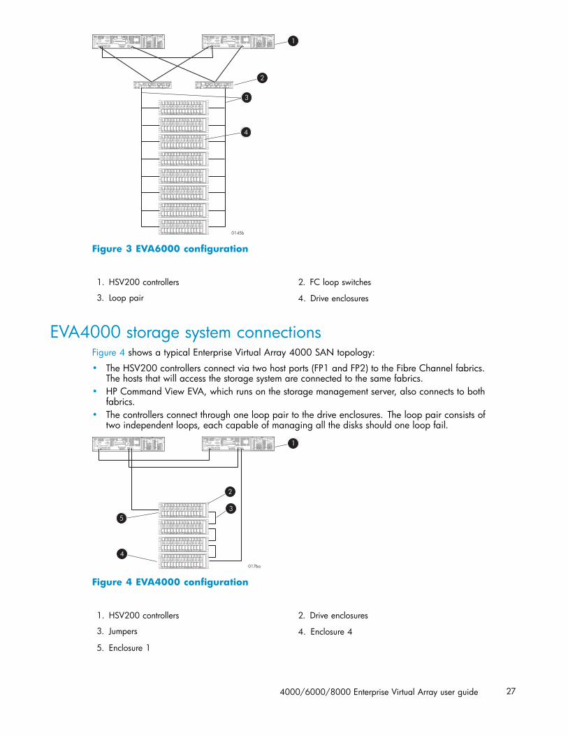
Figure 3 EVA6000 configuration
1. HSV200 controllers 2. FC loop switches
3. Loop pair 4. Drive enclosures
EVA4000 storage system connectionsFigure 4 shows a typical Enterprise Virtual Array 4000 SAN topology:
• The HSV200 controllers connect via two host ports (FP1 and FP2) to the Fibre Channel fabrics.The hosts that will access the storage system are connected to the same fabrics.
• HP Command View EVA, which runs on the storage management server, also connects to bothfabrics.
• The controllers connect through one loop pair to the drive enclosures. The loop pair consists oftwo independent loops, each capable of managing all the disks should one loop fail.
Figure 4 EVA4000 configuration
1. HSV200 controllers 2. Drive enclosures
3. Jumpers 4. Enclosure 4
5. Enclosure 1
4000/6000/8000 Enterprise Virtual Array user guide 27
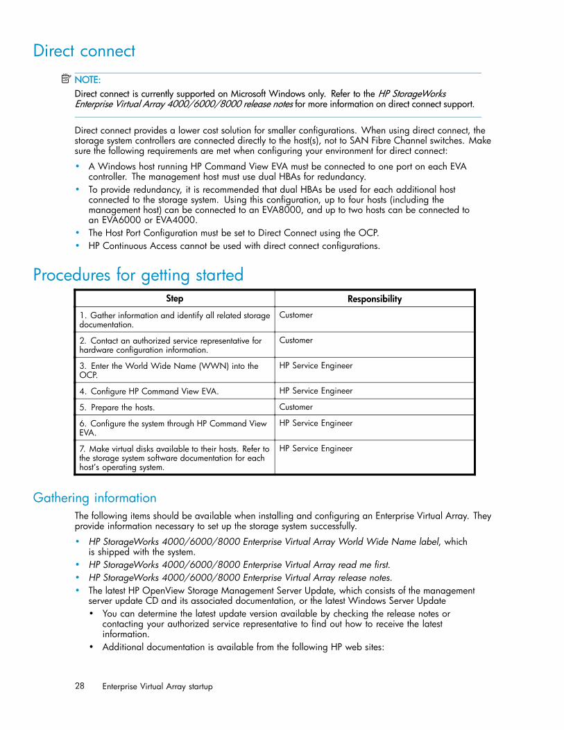
Direct connectNOTE:Direct connect is currently supported on Microsoft Windows only. Refer to the HP StorageWorksEnterprise Virtual Array 4000/6000/8000 release notes for more information on direct connect support.
Direct connect provides a lower cost solution for smaller configurations. When using direct connect, thestorage system controllers are connected directly to the host(s), not to SAN Fibre Channel switches. Makesure the following requirements are met when configuring your environment for direct connect:
• A Windows host running HP Command View EVA must be connected to one port on each EVAcontroller. The management host must use dual HBAs for redundancy.
• To provide redundancy, it is recommended that dual HBAs be used for each additional hostconnected to the storage system. Using this configuration, up to four hosts (including themanagement host) can be connected to an EVA8000, and up to two hosts can be connected toan EVA6000 or EVA4000.
• The Host Port Configuration must be set to Direct Connect using the OCP.• HP Continuous Access cannot be used with direct connect configurations.
Procedures for getting startedStep Responsibility
1. Gather information and identify all related storagedocumentation.
Customer
2. Contact an authorized service representative forhardware configuration information.
Customer
3. Enter the World Wide Name (WWN) into theOCP.
HP Service Engineer
4. Configure HP Command View EVA. HP Service Engineer
5. Prepare the hosts. Customer
6. Configure the system through HP Command ViewEVA.
HP Service Engineer
7. Make virtual disks available to their hosts. Refer tothe storage system software documentation for eachhost’s operating system.
HP Service Engineer
Gathering informationThe following items should be available when installing and configuring an Enterprise Virtual Array. Theyprovide information necessary to set up the storage system successfully.
• HP StorageWorks 4000/6000/8000 Enterprise Virtual Array World Wide Name label, whichis shipped with the system.
• HP StorageWorks 4000/6000/8000 Enterprise Virtual Array read me first.• HP StorageWorks 4000/6000/8000 Enterprise Virtual Array release notes.• The latest HP OpenView Storage Management Server Update, which consists of the management
server update CD and its associated documentation, or the latest Windows Server Update• You can determine the latest update version available by checking the release notes or
contacting your authorized service representative to find out how to receive the latestinformation.
• Additional documentation is available from the following HP web sites:
28 Enterprise Virtual Array startup

• http://www.hp.com/go/eva4000• http://www.hp.com/go/eva6000• http://www.hp.com/go/eva8000
Locate these items and keep them handy. You will need them for the procedures in this manual.
Host informationMake a list of information for each host computer that will be accessing the storage system. You will needthe following information for each host:
• The LAN name of the host• A list of World Wide Names of the FC adapters, also called host bus adapters, through which
the host will connect to the fabric or fabrics that provide access to the storage system• Operating system type• Available LUN numbers
Setting up a controller pair using the OCP
NOTE:This procedure should be performed by an HP authorized service representative.
Two pieces of data must be entered during initial setup using the controller OCP:
• World Wide Name (WWN)—Required to complete setup. This procedure should be performedby an HP authorized service representative.
• Storage system password—Optional. A password provides security allowing only specificinstances of HP Command View EVA to access the storage system.
The OCP on either controller can be used to input the WWN and password data. For more informationabout the OCP, see "Operator Control Panel" on page 70.
Table 2 lists the push button functions when entering the WWN, WWN checksum, and password data.
Table 2 Push button functions
Button Function
Selects a character by scrolling up through the character list one character at a time.
Moves forward one character. If you accept an incorrect character, you can move throughall 16 characters, one character at a time, until you display the incorrect character. Youcan then change the character.
Selects a character by scrolling down through the character list one character at a time.
Moves backward one character.
ESC Returns to the default display.
ENTER Accepts all the characters entered.
Entering the WWNFibre Channel protocol requires that each controller pair have a unique WWN. This 16-characteralphanumeric name identifies the controller pair on the storage system. Two WWN labels attached to therack identify the storage system WWN and checksum. See Figure 5.
4000/6000/8000 Enterprise Virtual Array user guide 29

NOTE:• The WWN is unique to a controller pair and cannot be used for any other controller pair or device
anywhere on the network.• This is the only WWN applicable to any controller installed in a specific physical location, even a
replacement controller.• Once a WWN is assigned to a controller, you cannot change the WWN while the controller is part
of the same storage system.
0108b
1
Figure 5 Location of the World Wide Name labels
1. World Wide Name labels
Complete the following procedure to assign the WWN to each pair of controllers.
1. Turn the power switches on both controllers off.
2. Apply power to the rack.
3. Turn the power switch on both controllers on.
NOTE:Notifications of the startup test steps that have been executed are displayed while thecontroller is booting. It may take up to two minutes for the steps to display. The defaultWWN entry display has a 0 in each of the 16 positions.
4. Press or until the first character of the WWN is displayed. Press to accept this characterand select the next.
5. Repeat Step 4 to enter the remaining characters.
6. Press Enter to accept the WWN and select the checksum entry mode.
Entering the WWN checksumThe second part of the WWN entry procedure is to enter the two-character checksum, as follows.
1. Verify that the initial WWN checksum displays 0 in both positions.
2. Press or until the first checksum character is displayed. Press to accept this character andselect the second character.
3. Press or until the second character is displayed. Press Enter to accept the checksum and exit.
4. Verify that the default display is automatically selected. This indicates that the checksum is valid.
30 Enterprise Virtual Array startup

NOTE:If you enter an incorrect WWN or checksum, the system will reject the data and you must repeat theprocedure.
Entering the storage system passwordThe eight-character storage system password feature enables you to restrict management access to thestorage system.
Complete the following procedure to set the password:
1. Select a unique, eight-character password.
2. With either of the default menus (Storage System Name or World Wide Name) displayed, pressthree times to display System Password.
3. Press to display Change Password?
4. Press Enter for yes.
The default password, AAAAAAAA, is displayed.
5. Press or to select the desired character.
6. Press to accept this character and select the next character.
7. Repeat the process to enter the remaining password characters.
8. Press Enter to enter the password and return to the default display.
Installing HP Command View EVAHP Command View EVA is installed on the HP OpenView Storage Management Server or aWindows host and runs in the OpenView environment. Installation may be skipped if the latestversion of HP Command View EVA is running. Verify the latest version at the HP web site:http://h18006.www1.hp.com/storage/software.html.
To install a new version, locate the management server update CD-ROM and the associateddocumentation that was shipped with your storage system. Follow the instructions in the HP OpenViewStorage Management Server update installation card to install the new software.
Installing optional EVA software licensesIf you purchased optional EVA software, it will be necessary to install the license. Optional softwareavailable for the Enterprise Virtual Array includes HP Business Copy and HP Continuous Access.Installation instructions are included with the license.
4000/6000/8000 Enterprise Virtual Array user guide 31

32 Enterprise Virtual Array startup
3 Enterprise Virtual Arrayoperation
This chapter presents the tasks that you might need to perform during normal operation of the storagesystem.
Best practicesFor useful information on managing and configuring your storage system, refer to the HPStorageWorks Enterprise Virtual Array configuration best practices white paper available fromhttp://h71028.www7.hp.com/ERC/downloads/5982-9140EN.pdf.
Operating tips and information
Reserving adequate free spaceTo ensure efficient storage system operation, a certain amount of unallocated capacity, or free space,should be reserved in each disk group. The recommended amount of free space is influenced by yoursystem configuration. For guidance on how much free space to reserve, refer to the HP StorageWorksEnterprise Virtual Array configuration best practices white paper. See Best practices.
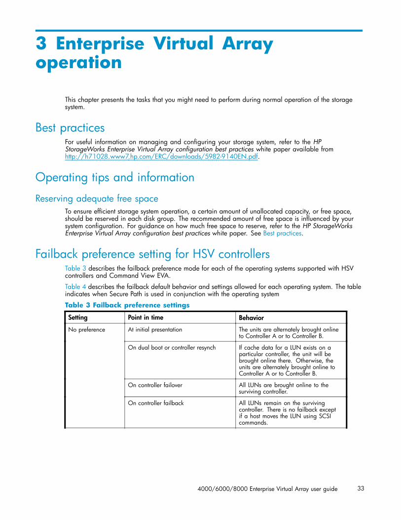
Failback preference setting for HSV controllersTable 3 describes the failback preference mode for each of the operating systems supported with HSVcontrollers and Command View EVA.
Table 4 describes the failback default behavior and settings allowed for each operating system. The tableindicates when Secure Path is used in conjunction with the operating system
Table 3 Failback preference settings
Setting Point in time Behavior
At initial presentation The units are alternately brought onlineto Controller A or to Controller B.
On dual boot or controller resynch If cache data for a LUN exists on aparticular controller, the unit will bebrought online there. Otherwise, theunits are alternately brought online toController A or to Controller B.
On controller failover All LUNs are brought online to thesurviving controller.
No preference
On controller failback All LUNs remain on the survivingcontroller. There is no failback exceptif a host moves the LUN using SCSIcommands.
4000/6000/8000 Enterprise Virtual Array user guide 33
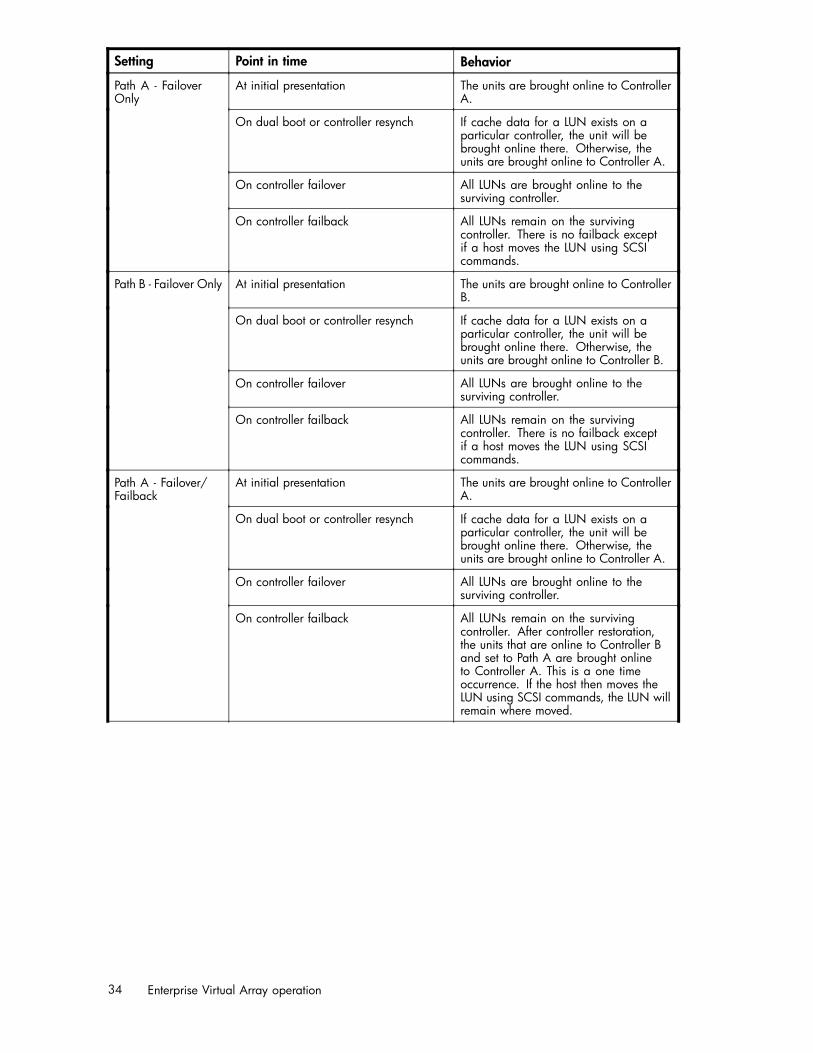
Setting Point in time Behavior
At initial presentation The units are brought online to ControllerA.
On dual boot or controller resynch If cache data for a LUN exists on aparticular controller, the unit will bebrought online there. Otherwise, theunits are brought online to Controller A.
On controller failover All LUNs are brought online to thesurviving controller.
Path A - FailoverOnly
On controller failback All LUNs remain on the survivingcontroller. There is no failback exceptif a host moves the LUN using SCSIcommands.
At initial presentation The units are brought online to ControllerB.
On dual boot or controller resynch If cache data for a LUN exists on aparticular controller, the unit will bebrought online there. Otherwise, theunits are brought online to Controller B.
On controller failover All LUNs are brought online to thesurviving controller.
Path B - Failover Only
On controller failback All LUNs remain on the survivingcontroller. There is no failback exceptif a host moves the LUN using SCSIcommands.
At initial presentation The units are brought online to ControllerA.
On dual boot or controller resynch If cache data for a LUN exists on aparticular controller, the unit will bebrought online there. Otherwise, theunits are brought online to Controller A.
On controller failover All LUNs are brought online to thesurviving controller.
Path A - Failover/Failback
On controller failback All LUNs remain on the survivingcontroller. After controller restoration,the units that are online to Controller Band set to Path A are brought onlineto Controller A. This is a one timeoccurrence. If the host then moves theLUN using SCSI commands, the LUN willremain where moved.
34 Enterprise Virtual Array operation

Setting Point in time Behavior
At initial presentation The units are brought online to ControllerB.
On dual boot or controller resynch If cache data for a LUN exists on aparticular controller, the unit will bebrought online there. Otherwise, theunits are brought online to Controller B.
On controller failover All LUNs are brought online to thesurviving controller.
Path B - Failover/Failback
On controller failback All LUNs remain on the survivingcontroller. After controller restoration,the units that are online to ControllerA and set to Path B are brought onlineto Controller B. This is a one timeoccurrence. If the host then moves theLUN using SCSI commands, the LUN willremain where moved.
Table 4 Failback Settings by Operating System
Operating system Default behavior Settings supported
Windows® Secure Path Autoback done by the host No Preference, Path A/B - FailoverOnly.
Sun Solaris® Secure Path Autoback done by the host No Preference, Path A/B - FailoverOnly.
HP-UX Secure Path Autoback done by the host No Preference, Path A/B - FailoverOnly.
IBM AIX Secure Path Autoback done by the host No Preference, Path A/B - FailoverOnly.
Tru64 UNIX Host follows the unit All settings allowed.Recommended setting: PathA/B - Failover/Failback.
VMS (7.3-1 and greater) Host follows the unit All settings allowed.Recommended setting: PathA/B - Failover/Failback.
Changing virtual disk failover/failback settingChanging the failover/failback setting of a virtual disk may impact which controller presents the disk.Table 5 identifies the presentation behavior that results when the failover/failback setting for a virtualdisk is changed.
4000/6000/8000 Enterprise Virtual Array user guide 35

NOTE:If the new setting causes the presentation of the virtual disk to move to a new controller, any snapshotsor snapclones associated with the virtual disk will also be moved.
Table 5 Impact on virtual disk presentation when changing failover/failback setting
New setting Impact on virtual disk presentation
No Preference None. The disk maintains its original presentation
Path A Failover If the disk is currently presented on controller B, it is moved tocontroller A. If the disk is on controller A, it remains there.
Path B Failover If the disk is currently presented on controller A, it is moved tocontroller B. If the disk is on controller B, it remains there.
Path A Failover/Failback If the disk is currently presented on controller B, it is moved tocontroller A. If the disk is on controller A, it remains there.
Path B Failover/Failback If the disk is currently presented on controller A, it is moved tocontroller B. If the disk is on controller B, it remains there.
Storage system shutdown and powerupThe storage system is shut down using HP Command View EVA. The shutdown process performs thefollowing functions in the indicated order:
1. Flushes cache2. Removes power from the controllers3. Disables cache battery power4. Removes power from the drive enclosures5. Disconnects the system from HP Command View EVA
NOTE:The storage system may take a long time to complete the necessary cache flush during controllershutdown when snapshots are being used. The delay may be particularly long if multiple child snapshotsare used, or if there has been a large amount of write activity to the snapshot source Vdisk.
Shutting down the storage systemTo shut the storage system down, perform the following steps:
1. Start HP Command View EVA.
2. Select the appropriate storage system in the Navigation pane.
The Initialized Storage System Properties window for the selected storage system opens.
3. Click System options.
The System Options window opens.
4. Click Shut down.
The Shutdown Options window opens.
5. Under System Shutdown click Power Down. If you want to delay the initiation of the shutdown, enterthe number of minutes in the Shutdown delay field.
36 Enterprise Virtual Array operation

The controllers complete an orderly shutdown and then power off. The disk enclosures then poweroff. Wait for the shutdown to complete.
6. Turn off the power switch on the rear of each HSV controller.
7. Turn off the circuit breakers on both of the EVA rack Power Distribution Units (PDU).
8. If your management server is an SMA and you are not using it to manage other storage arrays, shutdown the SMA. From the SMA user interface, click Settings > Maintenance > Shutdown.
Powering up the storage systemTo power up a storage system, perform the following steps:
1. Verify that each fabric Fibre Channel switch to which the HSV controllers are connected is poweredup and fully booted. The LED power indicator on each switch should be on.
If you must power up the SAN switches, wait for them to complete their power-on boot processbefore proceeding. This may take several minutes.
2. If the management server you shut down is an SMA, power it on and wait for it to completely boot.Verify the SMA is running by logging into it using the web interface.
NOTE:Before applying power to the rack, ensure that the power switch on each HSV controlleris off.
3. Power on the circuit breakers on both EVA rack PDUs. Verify that all drive enclosures are operatingproperly. The status indicator and the power indicator should be on (green).
4. Wait three minutes and then verify that all disk drives are ready. The drive ready indicator andthe drive online indicator should be on (green).
5. Power on the upper controller. It takes the roll of master controller.
6. Wait 10 seconds and then power on the lower controller. It takes the roll of slave controller.
7. Verify that the (Operator Control Panel) OCP display on each controller displays the storage systemname and the EVA WWN.
8. Start HP Command View EVA and verify connection to the storage system. If the storage system isnot visible, click HSV Storage Network in the Navigation pane then click Discover in the Contentpane to discover the array.
NOTE:If the storage system is still not visible, reboot the management server to re-establish thecommunication link.
9. Check the storage system status using HP Command View EVA to ensure everything is operatingproperly. If any status indicator is not normal, check the log files or contact your HP—authorizedservice provider for assistance.
Saving storage system configuration dataAs part of an overall data protection strategy, storage system configuration data should saved duringinitial installation, and whenever major configuration changes are made to the storage system. Thisincludes adding or removing disk drives, creating or deleting disk groups, and adding or deleting virtualdisks. The saved configuration data can save substantial time should it ever become necessary tore-initialize the storage system. The configuration data is saved to a series of files stored in a locationother than on the storage system.
4000/6000/8000 Enterprise Virtual Array user guide 37

This procedure can be performed from the SAN Management Appliance (SMA) or management serverwhere the Command View EVA application is installed, or any host that can run the Storage SystemScripting Utility (SSSU) to communicate with the Command View EVA application server.
NOTE:SSSU version 4 is required for HP Command View EVA 4.0 and later. For more information on usingSSSU, refer to the HP StorageWorks Storage System Scripting Utility reference, which can be downloadedfrom the following web site:http://h18006.www1.hp.com/products/storage/software/cmdvieweva/index.htmlClick Support & Documentation.
1. Run SSSU on the platform and operating system of your choice.
2. Enter SELECT MANAGER and select the management server.
3. Enter SHOW SYSTEM to determine which storage systems are managed by this instance of HPCommand View EVA.
4. Enter SELECT SYSTEM to select the appropriate storage system from which to collect configurationdata.
5. Enter CAPTURE CONFIGURATION, specifying the full path and filename of the output files forthe configuration data.
The configuration data is stored in a series of from one to five files, which are SSSU scripts. Thefile names begin with the name you choose, with the restore step appended. For example,if you specify a file name of LargeEVA.txt, the resultant configuration files would beLargeEVA_Step1A.txt, LargeEVA_Step1B, etc.
The contents of the configuration files can be viewed with a text editor.
NOTE:If the storage system contains disk drives of different capacities, the SSSU procedures used do notguarantee that disk drives of the same capacity will be exclusively added to the same disk group. The useof this method does not ensure that there will be only disk drives of the same capacity in each disk group.
The following examples illustrate how to save and restore the storage system configuration data usingSSSU on a Windows host.
Example 1. Saving configuration data using SSSU on a Windows Host
Run SSSU from a DOS Command Window on the SMA, a Windows Workstation or a Windows Serverthat can access the SMA by TCP/IP or the management host running Command View.
1. Click Run on the Window Start menu.
2. Enter cmd in the Open field to open the DOS Command Window.
3. Change to the directory (CD) in which you have installed SSSU. For example, C:> cd \SSSUDir
4. Enter SSSU to run the application.
5. Enter SELECT MANAGER <SMAname or ip_addr> user=<username> pass=<userpass-word>.
6. Enter SHOW SYSTEM to display the EVA storage systems managed by the SMA or Windows Host.
7. Enter SELECT SYSTEM <EVA_Name>, where EVA_name is the name of the storage system.
The storage system name is case sensitive. If there are spaces between the letters in the name, quotesmust enclose the name. For example, SELECT SYSTEM “Large EVA”.
38 Enterprise Virtual Array operation

8. Enter CAPTURE CONFIGURATION <pathname\filename>, where pathname identifies thelocation where the configuration files will be saved, and filename is the name used as the prefix forthe configurations files. For example, CAPTURE CONFIGURATION c:\EVAConfig\LargeEVA
9. Enter EXIT to close the DOS Command Window.
Example 2. Restoring configuration data using SSSU on a Windows Host
If it is necessary to restore the storage system configuration, it can be done using the
1. Click Run on the Window Start menu.
2. Enter cmd in the Open field to open the DOS Command Window.
3. Change to the directory (CD) in which you have installed SSSU. For example, C:> cd \SSSUDir
4. Enter SSSU to run the application.
5. Enter FILE <pathname\filename>, where pathname identifies the location where theconfiguration files are be saved and filename is the name of the first configuration file. For example,FILE c:\EVAConfig\LargeEVA_Step1A.txt
6. Repeat the preceding step for each configuration file.
Adding disk drives to the storage systemAs your storage requirements grow, you may be adding disk drives to your storage system. Adding newdisk drives is the easiest way to increase the storage capacity of the storage system. Disk drives can beadded online without impacting storage system operation.
Guidelines for adding disk drivesWhen adding new disk drives to the storage system, you should ensure that the disk drives are installedin the correct positions to maintain availability. The disk drives should be distributed across the diskenclosures to protect against the failure of a single disk enclosure.
Use the following guidelines when adding disk drives to your storage system:
• Install high performance and FATA disk drives in separate groups. These different drive types mustbe in separate disk groups. You may also want to consider separating different drive capacitiesand spindle speeds into different groups.
• The disk drives should be distributed evenly across the disk enclosures. The number of disks ofa given type in each enclosure should not differ by more than one. For example, no enclosureshould have two disks until all the other enclosures have at least one.
• Disk drives should be installed in vertical columns within the disk enclosures. Add drives verticallyin multiples of eight, completely filling columns if possible. Disk groups are more robust if filledwith the same number of disk drives in each enclosure. See Figure 7 for an example.
NOTE:When adding multiple disk drives, add a disk and wait for its activity indicator (1) to stop flashing(up to 90 seconds) before installing the next disk (see Figure 6). This procedure must be followed toavoid unexpected EVA system behavior.
4000/6000/8000 Enterprise Virtual Array user guide 39

Figure 6 Disk drive activity indicator
Creating disk groupsThe new disks you add will typically be used to create new disk groups. Although you cannot selectwhich disks will be part of a disk group, you can control this by building the disk groups sequentially.
Add the disk drives required for the first disk group, and then create a disk group using these disk drives.Now add the disk drives for the second disk group, and then create that disk group. This process givesyou control over which disk drives are included in each disk group. Figure 7 shows the sequentialbuilding of vertical disk groups.
NOTE:Standard and FATA disk drives must be in separate disk groups. Disk drives of different capacities andspindle speeds can be included in the same disk group, but you may want to consider separatingthem into separate disk groups.
40 Enterprise Virtual Array operation
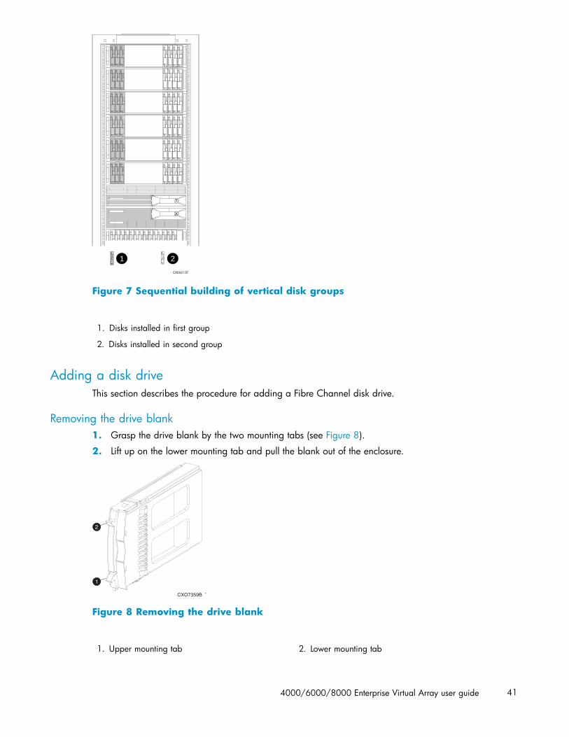
CX8167-ST
21
Figure 7 Sequential building of vertical disk groups
1. Disks installed in first group
2. Disks installed in second group
Adding a disk driveThis section describes the procedure for adding a Fibre Channel disk drive.
Removing the drive blank1. Grasp the drive blank by the two mounting tabs (see Figure 8).
2. Lift up on the lower mounting tab and pull the blank out of the enclosure.
CXO7359B ˚
1
2
Figure 8 Removing the drive blank
1. Upper mounting tab 2. Lower mounting tab
4000/6000/8000 Enterprise Virtual Array user guide 41
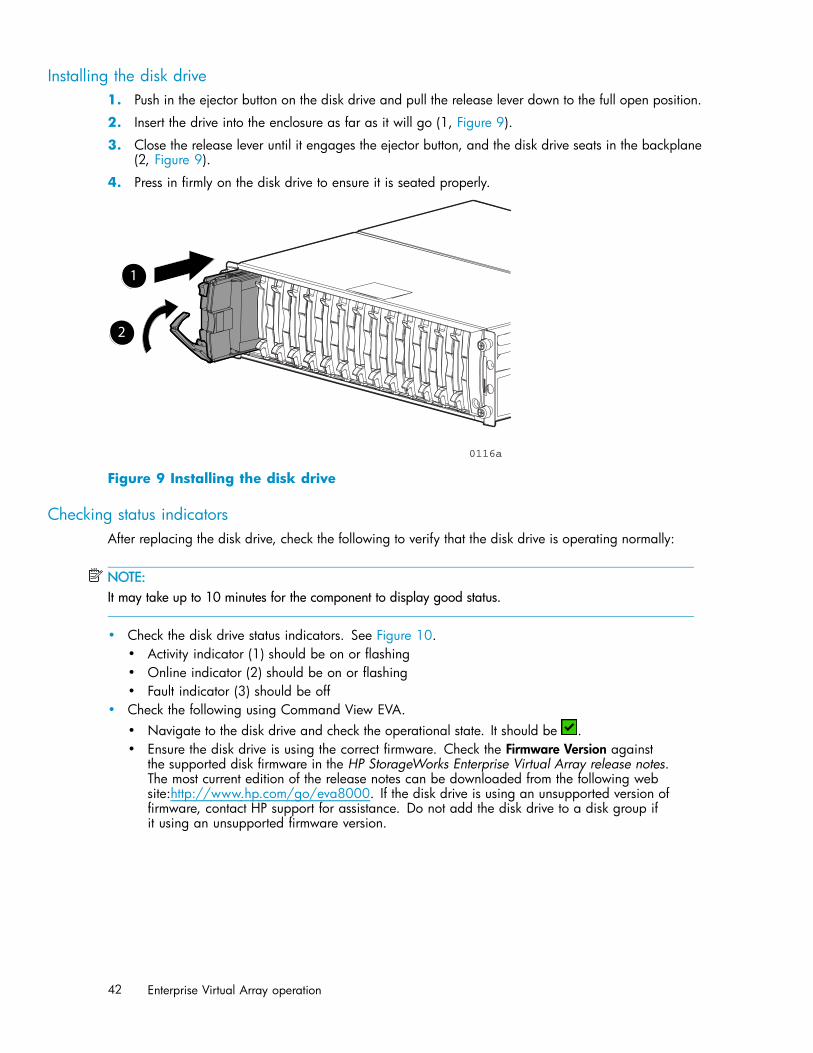
Installing the disk drive1. Push in the ejector button on the disk drive and pull the release lever down to the full open position.
2. Insert the drive into the enclosure as far as it will go (1, Figure 9).
3. Close the release lever until it engages the ejector button, and the disk drive seats in the backplane(2, Figure 9).
4. Press in firmly on the disk drive to ensure it is seated properly.
0116a
2
1
Figure 9 Installing the disk drive
Checking status indicatorsAfter replacing the disk drive, check the following to verify that the disk drive is operating normally:
NOTE:It may take up to 10 minutes for the component to display good status.
• Check the disk drive status indicators. See Figure 10.• Activity indicator (1) should be on or flashing• Online indicator (2) should be on or flashing• Fault indicator (3) should be off
• Check the following using Command View EVA.• Navigate to the disk drive and check the operational state. It should be .• Ensure the disk drive is using the correct firmware. Check the Firmware Version against
the supported disk firmware in the HP StorageWorks Enterprise Virtual Array release notes.The most current edition of the release notes can be downloaded from the following website:http://www.hp.com/go/eva8000. If the disk drive is using an unsupported version offirmware, contact HP support for assistance. Do not add the disk drive to a disk group ifit using an unsupported firmware version.
42 Enterprise Virtual Array operation
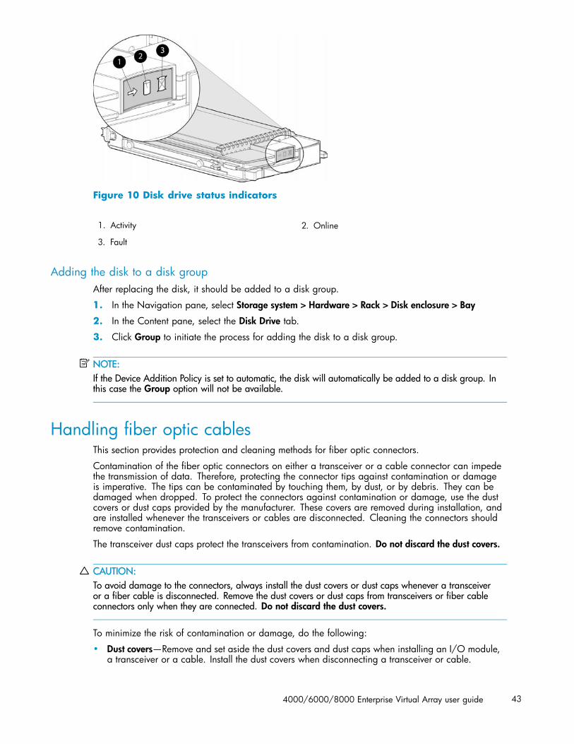
Figure 10 Disk drive status indicators
1. Activity 2. Online
3. Fault
Adding the disk to a disk groupAfter replacing the disk, it should be added to a disk group.
1. In the Navigation pane, select Storage system > Hardware > Rack > Disk enclosure > Bay
2. In the Content pane, select the Disk Drive tab.
3. Click Group to initiate the process for adding the disk to a disk group.
NOTE:If the Device Addition Policy is set to automatic, the disk will automatically be added to a disk group. Inthis case the Group option will not be available.
Handling fiber optic cablesThis section provides protection and cleaning methods for fiber optic connectors.
Contamination of the fiber optic connectors on either a transceiver or a cable connector can impedethe transmission of data. Therefore, protecting the connector tips against contamination or damageis imperative. The tips can be contaminated by touching them, by dust, or by debris. They can bedamaged when dropped. To protect the connectors against contamination or damage, use the dustcovers or dust caps provided by the manufacturer. These covers are removed during installation, andare installed whenever the transceivers or cables are disconnected. Cleaning the connectors shouldremove contamination.
The transceiver dust caps protect the transceivers from contamination. Do not discard the dust covers.
CAUTION:To avoid damage to the connectors, always install the dust covers or dust caps whenever a transceiveror a fiber cable is disconnected. Remove the dust covers or dust caps from transceivers or fiber cableconnectors only when they are connected. Do not discard the dust covers.
To minimize the risk of contamination or damage, do the following:
• Dust covers—Remove and set aside the dust covers and dust caps when installing an I/O module,a transceiver or a cable. Install the dust covers when disconnecting a transceiver or cable.
4000/6000/8000 Enterprise Virtual Array user guide 43
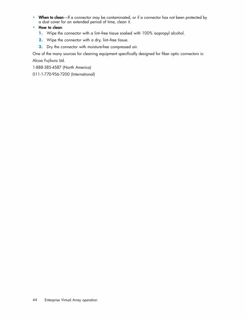
• When to clean—If a connector may be contaminated, or if a connector has not been protected bya dust cover for an extended period of time, clean it.
• How to clean:1. Wipe the connector with a lint–free tissue soaked with 100% isopropyl alcohol.
2. Wipe the connector with a dry, lint–free tissue.
3. Dry the connector with moisture-free compressed air.
One of the many sources for cleaning equipment specifically designed for fiber optic connectors is:
Alcoa Fujikura Ltd.
1-888-385-4587 (North America)
011-1-770-956-7200 (International)
44 Enterprise Virtual Array operation

4 Enterprise Virtual Arrayhardware components
This chapter describes the Enterprise Virtual Array hardware components. Topics to be discussed include:
• Fibre Channel drive enclosures• Fibre Channel loop switches• HSV controllers• Racks
Fibre Channel drive enclosuresThe drive enclosure contains the disk drives used for data storage. A storage system includes multipledrive enclosures. The major components of the enclosure are:
• 2.125–Gb, dual loop, 14–drive enclosure• Dual-loop, Fibre Channel drive enclosure I/O modules• Copper Fibre Channel cables• Fibre Channel disk drives and drive blanks• Power supplies• Blowers• Cache batteries• EMU
Enclosure layoutThe disk drives mount in bays in the front of the enclosure. The bays are numbered sequentially from leftto right. A drive is referred to by its bay number. Enclosure status indicators are located in the lower-right,front corner. Figure 11 shows the front and rear views of the FC drive enclosure.
4000/6000/8000 Enterprise Virtual Array user guide 45

0112a
Front
Rear
1 2
3 4 56 78 9
10
Figure 11 FC drive enclosure—front and rear views
1. Drive bay 1 2. Drive bay 14
3. EMU 4. I/O module B
5. Blower 1 6. Power supply 1
7. Blower 2 8. Power supply 2
9. I/O module A 10. Status indicators (EMU, enclosure power,enclosure fault)
I/O modulesTwo I/O modules provide the interface between the drive enclosure and the host controllers. See Figure12. They route data to and from the disk drives using Loop A and Loop B, the dual-loop configuration.For redundancy, only dual-controller, dual-loop operation is supported. Each controller is connected toboth I/O modules in the drive enclosure.
46 Enterprise Virtual Array hardware components
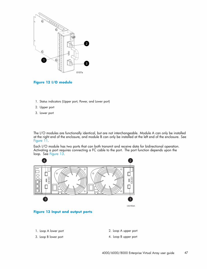
0107a
1
2
3
Figure 12 I/O module
1. Status indicators (Upper port, Power, and Lower port)
2. Upper port
3. Lower port
The I/O modules are functionally identical, but are not interchangeable. Module A can only be installedat the right end of the enclosure, and module B can only be installed at the left end of the enclosure. SeeFigure 11.
Each I/O module has two ports that can both transmit and receive data for bidirectional operation.Activating a port requires connecting a FC cable to the port. The port function depends upon theloop. See Figure 13.
CXO7954A
3 1
4 2
Figure 13 Input and output ports
1. Loop A lower port 2. Loop A upper port
3. Loop B lower port 4. Loop B upper port
4000/6000/8000 Enterprise Virtual Array user guide 47

I/O module status indicatorsThere are three status indicators on the I/O module. See Figure 12. The status indicator states foran operational I/O module are shown in Table 6. Table 7 shows the status indicator states for anon-operational I/O module.
Table 6 Operational I/O module status indicators
Upper Power Lower Descriptions
Off On Off • I/O Module is operational
On Flashing, then On On • Top port—Fibre Channel drive enclosure signal detected.• Power—Flashes for about 90 seconds after initial power application,
then remains constant.• Bottom port—Fibre Channel drive enclosure signal detected.
On On On • Top port—Fibre Channel drive enclosure signal detected.• Power—Present.• Bottom port—Fibre Channel drive enclosure signal detected.
Flashing Flashing Flashing • When the locate function is active, all three indicators flashsimultaneously. The Locate function overrides all other indicatorfunctions. Therefore, an error could be detected while the Locatefunction is active and not be indicated until the Locate actionterminates.
48 Enterprise Virtual Array hardware components

Table 7 Non-operational I/O module status indicators
Upper Power Lower Descriptions
On On Off • Top port—Fibre Channel drive enclosure signal detected.• Power—Present.• Bottom port—No Fibre Channel drive enclosure signal detected.
Check transceiver and fiber cable connections.NOTE:This status applies to configurations with and without FC loopswitches.
Off On On • Top port—No Fibre Channel drive enclosure signal detected. Checktransceiver and fiber cable connections.
• Power—Present.• Bottom port—Fibre Channel drive enclosure signal detected .
Flashing On On • Top port—EMU detected possible transceiver problem. Checktransceiver and fiber cable connections.
• Power—Present.• Bottom port—Fibre Channel drive enclosure signal detected .
On On Flashing • Top port—Fibre Channel drive enclosure signal detected.• Power—Present.• Bottom port—EMU detected possible transceiver problem. Check
transceiver and fiber cable connections.NOTE:The EMU will not flash the lower indicator on its own. It will flashonly in response to a locate command. You can flash each of thelights independently during a locate action.
Off Off Off • No I/O module power.• I/O module is nonoperational.• Check power supplies. If power supplies are operational, replace
I/O module.
Fibre Optic Fibre Channel cablesThe Enterprise Virtual Array uses orange, 50-μm, multi-mode, fiber optic cables for connection to theSAN. The fiber optic cable assembly consists of two, 2–m fiber optic strands and small form-factorconnectors on each end. See Figure 14.
To ensure optimum operation, the fiber optic cable components require protection from contaminationand mechanical hazards. Failure to provide this protection can cause degraded operation. Observe thefollowing precautions when using fiber optic cables.
• To avoid breaking the fiber within the cablet:• Do not kink the cable• Do not use a cable bend-radius of less than 30 mm (1.18 in)
• To avoid deforming, or possibly breaking the fiber within the cable, do not place heavy objectson the cable.
• To avoid contaminating the optical connectors:• Do not touch the connectors• Never leave the connectors exposed to the air• Install a dust cover on each transceiver and fiber cable connector when they are disconnected
4000/6000/8000 Enterprise Virtual Array user guide 49

If an open connector is exposed to dust, or there is any doubt about the cleanliness of the connector,clean the connector as described in Handling fiber optic cables.
CXO7972A
Figure 14 Fibre Optic Fibre Channel cable
Copper Fibre Channel cablesThe Enterprise Virtual Array Fibre Channel 10000-Series implementation uses copper Fibre Channelcables to connect the drive enclosures to each other, or to the loop switches and to the HSV controllers.The cables are available in 0.6–meter and 2.0–meter lengths. Copper cables provide performancecomparable to fiber optic cables. Copper cable connectors differ from fiber optic small form-factorconnectors (see Figure 15).
8164A-ST
Figure 15 Copper Fibre Channel cable
Fibre Channel disk drivesThe Fibre Channel disk drives are hot-pluggable and include the following features:
• Dual-ported 2–Gbps Fibre Channel drive enclosure interface that allows up to 120 disk drives tobe supported per Fibre Channel drive enclosure pair.
• Compact, direct-connect design for maximum storage density and increased reliability andsignal integrity.
• Both online high-performance disk drives and FATA disk drives in a variety of capacities andspindle speeds.
• Better vibration damping for improved performance.
Up to 14 disk drives can be installed in a drive enclosure.
Disk drive status indicatorsThree status indicators display the drive operational status. Figure 16 shows the disk drive statusindicators. Table 8 provides a description of each status indicator.
50 Enterprise Virtual Array hardware components

Figure 16 Disk drive status indicators
1. Activity 2. Online
3. Fault
Table 8 Disk drive status indicator descriptions
Status indicator Description
ActivityThis green status indicator flashes when the disk drive isbeing accessed. It is on when the drive is idle.
OnlineThe green status indicator is on when the disk drive isonline and operating normally. This indicator will be offin the following situations:• There is no controller on the bus.• +5.1 VDC is not available.• The drive is not properly installed in the enclosure.
FaultThis amber status indicator is on when there is a disk drivefailure. Depending on the host controller, this indicator mayflash when the controller detects an error condition.The amber status indicator flashes in synchronization withthe other two status indicators in response to the EMUlocate command.
Disk drive status displaysThe disk drive status indicators can assume three states: on, off, or flashing. The status indicators statesfor operational drive status are shown in Table 9. See Table 10 for the non-operational drive statusindicator states.
Table 9 Operational disk drive status indications
Activity Online Fault Description
Flashing On Off Initial startup.
On On Off The drive is online but is not being accessed.
Flashing Flashing Flashing The drive is being located.
Flashing On Off The drive is operational and active.
4000/6000/8000 Enterprise Virtual Array user guide 51

Table 10 Non-operational disk drive status indications
Activity Online Fault Description
On On On Indicates no connection or the controllers are offline.Recommended corrective actions:1. Check power supplies for proper operation.2. If defective, replace disk drive.
On Off Flashing Indicates disk drive error/not active. Recommendedcorrective actions:1. Verify FC loop continuity.2. Replace disk drive.
Disk drive blankTo maintain the proper enclosure air flow, a disk drive or a disk drive blank must be installed in eachdrive bay. The disk drive blank maintains proper airflow within the disk enclosure.
Power supplies and blowersThis section describes the function and operation of the disk enclosure power supplies and blowers.Figure 17 illustrates the major power supply and cooling components.
CXO7489A
1
3
1
4 5
2
5
6
Figure 17 Power supply and blower assembly components
1. Power supply
2. Status indicator
3. AC Input connector with bail
4. Module latch (wine-colored)
5. Blower tabs (wine-colored)
6. Blower
Power suppliesThe two power supplies mount in the rear of the enclosure (see Figure 27). The supplies are autorangingand operate on a country-specific AC input voltage of 202 to 240 VAC ±10%, 50 to 60 Hz, ±5%, (188to 264 VAC, 47 to 63 Hz).
The DC outputs of this power supply are:
52 Enterprise Virtual Array hardware components

• +5.1 VDC for the EMU, I/O module, backplane, and disk drives• +12.1 VDC for the disk drives• +12.5 VDC for the disk drives
The output of each power supply is 499 W, with a peak output of 681 W. A single power supply cansupport an enclosure with a full complement of disks.
The power supply circuitry provides protection against:
• Overloads• Short circuits• Overheating
Power supply status and diagnostic information is reported to the EMU with voltage, current, andtemperature signals.
See Regulatory Notices and Specifications for the enclosure power specifications.
The power supply temperature sensor provides a temperature range signal to the EMU, which uses thissignal to set the blower speed.
The power supply internal temperature can also control the speed of the blower. The higher the powersupply temperature, the faster the speed of the blower. If the power supply temperature exceeds a presetvalue, the power supply automatically shuts down.
BlowersThe power supply–mounted blowers cool the enclosure by circulating air through the enclosure. Theblowers, under the control of the EMU or the associated power supply, can operate at multiple speeds.This ensures that when the enclosure temperature changes the blowers can automatically adjust theair flow.
If a blower is operating too slowly or has stopped (a “blower failure”), internal circuitry automaticallyoperates the remaining blower at a higher speed. Simultaneously, the error condition is reported inseveral ways, including the power supply indicator, the audible alarm, the enclosure fault indicators,and the EMU alphanumeric display.
Should both blowers fail, the power supplies automatically shut down.
NOTE:The blowers are field-replaceable units and can be replaced, individually, while the system is running.The blowers are also interchangeable. The failure of a power supply +12.5 VDC circuit disables theassociated blower.
The status indicator on the blower (Figure 28) displays the status of both the power supply and the blower.See Table 11 for definitions of the indicator displays.
Table 11 Power supply/blower status indicators
Blower statusLED
Description
On Both the power supply and the blower are operational.
Flashing The power supply or the blower locate function is active.
Off The power supply or the blower is non–operational. Whenthere is a blower problem, the other blower runs at a higherspeed. Recommended corrective actions:• Check blower for proper operation. Replace if defective.• Check power supplies for proper operation. Replace if
defective.
4000/6000/8000 Enterprise Virtual Array user guide 53

Drive enclosure EMUThe EMU provides increased protection against catastrophic failures. The EMU detects conditions suchas failed power supplies, failed blowers, elevated temperatures, and external air sense faults andcommunicates these conditions to the storage system controllers.
The EMU for Fibre Channel-Arbitrated Loop (FC–AL) drive enclosures is fully compliant with SCSI-3Enclosure Services (SES), and mounts in the left rear bay of a drive enclosure (see 1, Figure 18).
CXO7971A1
Figure 18 EMU location
1. EMU
Controls and displaysFigure 19 illustrates the location and function of the EMU displays, controls, and connectors.
Figure 19 EMU controls and displays
1. Status indicators:a. EMU—This flashing green is the heartbeat for an operational EMU.b. Enclosure power—When both the +5 VDC and +12 VDC are correct, this green LED is on.c. Enclosure fault—This amber LED is normally off. The LED is lit when an enclosure error condition exists.
2. Alphanumeric display—A two-character, seven–segment alphanumeric display of the enclosure functionsand status.
3. Function select button—The primary function of this button is to select a display group function. Theindicator is on when an error condition exists.
4. Display group select button—This button is used to view display groups and control the audible alarm. Theindicator is on when the audible alarm is muted or disabled.
5. RS232 – for use by HP-authorized service representatives
6. LCD ONLY–unused
7. CAB ONLY–enclosure address bus connector
54 Enterprise Virtual Array hardware components
WARNING!To reduce the risk of electrical shock, fire, or damage to the equipment, do not plug telephone ortelecommunications connectors into the “RS232 ONLY” receptacle.
EMU functionsThe primary functions of the EMU include:
• Using the Enclosure Services Processor (ESP) to control the Enclosure Services Interface (ESI) andcommunicate with the controllers.
• Assigning the Enclosure Number (En), based upon the cabinet address bus feature.• Displaying the bay 1 loop ID.• Monitoring enclosure operation.• Detecting, reporting, recording, and displaying conditions.• Displaying EMU, enclosure, and element status.• Implementing automatic corrective actions for some conditions.• Providing enclosure status data to the controllers.• Reporting the WWN and the logical address of all disk drives.
NOTE:Although the EMU can determine the logical address of a drive, the EMU can neither display norchange this information. HP Command View EVA can display the addresses from the EMU-suppliedstatus information.
4000/6000/8000 Enterprise Virtual Array user guide 55
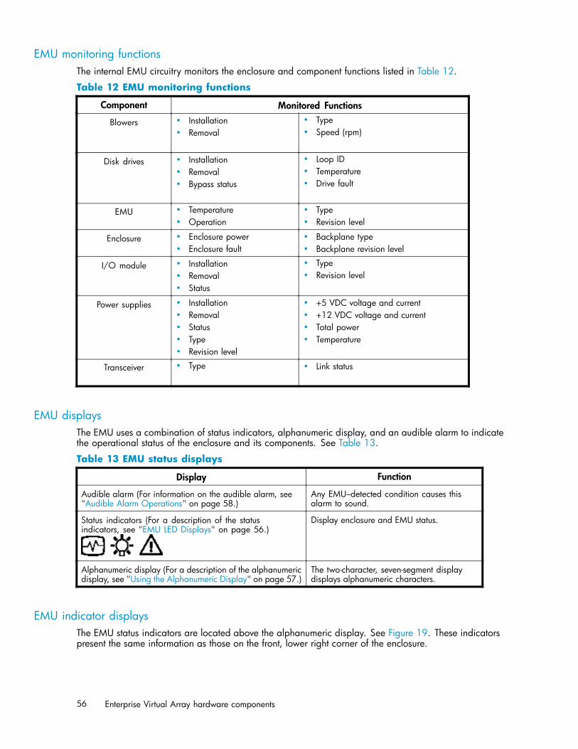
EMU monitoring functionsThe internal EMU circuitry monitors the enclosure and component functions listed in Table 12.
Table 12 EMU monitoring functions
Component Monitored Functions
Blowers • Installation• Removal
• Type• Speed (rpm)
Disk drives • Installation• Removal• Bypass status
• Loop ID• Temperature• Drive fault
EMU • Temperature• Operation
• Type• Revision level
Enclosure • Enclosure power• Enclosure fault
• Backplane type• Backplane revision level
I/O module • Installation• Removal• Status
• Type• Revision level
Power supplies • Installation• Removal• Status• Type• Revision level
• +5 VDC voltage and current• +12 VDC voltage and current• Total power• Temperature
Transceiver • Type • Link status
EMU displaysThe EMU uses a combination of status indicators, alphanumeric display, and an audible alarm to indicatethe operational status of the enclosure and its components. See Table 13.
Table 13 EMU status displays
Display Function
Audible alarm (For information on the audible alarm, see"Audible Alarm Operations" on page 58.)
Any EMU–detected condition causes thisalarm to sound.
Status indicators (For a description of the statusindicators, see "EMU LED Displays" on page 56.)
Display enclosure and EMU status.
Alphanumeric display (For a description of the alphanumericdisplay, see "Using the Alphanumeric Display" on page 57.)
The two-character, seven-segment displaydisplays alphanumeric characters.
EMU indicator displaysThe EMU status indicators are located above the alphanumeric display. See Figure 19. These indicatorspresent the same information as those on the front, lower right corner of the enclosure.
56 Enterprise Virtual Array hardware components
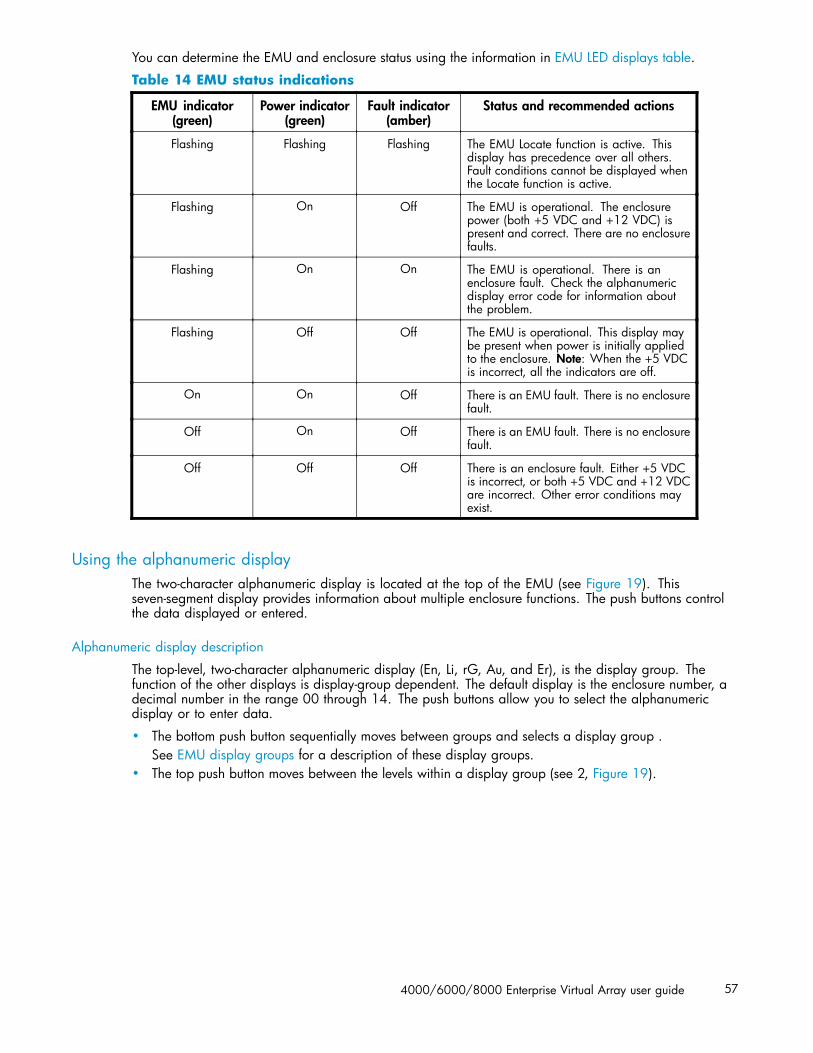
You can determine the EMU and enclosure status using the information in EMU LED displays table.
Table 14 EMU status indications
EMU indicator(green)
Power indicator(green)
Fault indicator(amber)
Status and recommended actions
Flashing Flashing Flashing The EMU Locate function is active. Thisdisplay has precedence over all others.Fault conditions cannot be displayed whenthe Locate function is active.
Flashing On Off The EMU is operational. The enclosurepower (both +5 VDC and +12 VDC) ispresent and correct. There are no enclosurefaults.
Flashing On On The EMU is operational. There is anenclosure fault. Check the alphanumericdisplay error code for information aboutthe problem.
Flashing Off Off The EMU is operational. This display maybe present when power is initially appliedto the enclosure. Note: When the +5 VDCis incorrect, all the indicators are off.
On On Off There is an EMU fault. There is no enclosurefault.
Off On Off There is an EMU fault. There is no enclosurefault.
Off Off Off There is an enclosure fault. Either +5 VDCis incorrect, or both +5 VDC and +12 VDCare incorrect. Other error conditions mayexist.
Using the alphanumeric displayThe two-character alphanumeric display is located at the top of the EMU (see Figure 19). Thisseven-segment display provides information about multiple enclosure functions. The push buttons controlthe data displayed or entered.
Alphanumeric display description
The top-level, two-character alphanumeric display (En, Li, rG, Au, and Er), is the display group. Thefunction of the other displays is display-group dependent. The default display is the enclosure number, adecimal number in the range 00 through 14. The push buttons allow you to select the alphanumericdisplay or to enter data.
• The bottom push button sequentially moves between groups and selects a display group .See EMU display groups for a description of these display groups.
• The top push button moves between the levels within a display group (see 2, Figure 19).
4000/6000/8000 Enterprise Virtual Array user guide 57

Display groups
When you press and release the bottom push button, the alphanumeric display selects a different displaygroup. EMU display groups describes the display groups.
Table 15 EMU display groups
Display Display group Description
En Enclosure Number The enclosure number is the default display and is a decimalnumber in the range 00 through 14. See Using the EnclosureNumber Feature for detailed information.
Li Bay 1 Loop ID This display group has a single sublevel display that definesthe enclosure bay 1 loop ID. Valid loop IDs are in the range00 through 7F.
rG Reporting Group This display group has two, two-digit displays that define thereporting group number in the range 0000 through 4095.
Au Audible Alarm This display group provides control over the audible alarm orhorn. The sublevel displays are audible alarm enabled (on) oraudible alarm disabled (oF). See Audible Alarm Operationsfor detailed information.
Fr Firmware Revision This display group defines the EMU code firmware version.
Er Error Condition This display group reads Er when there is an error condition.
NOTE:Any time you press and release the bottom push button the display will change to En, Li, rG, Au, or Er.
A flashing alphanumeric display indicates that you can edit an address, state, or view a condition report.
EMU push button status indicatorsThe push button status indicators display error conditions and the state of the audible alarm.
• When an error condition exists, the top push button status indicator is On.• For a single error condition, the status indicator is On until the error condition is viewed.• For multiple errors, the status indicator is On until the last error condition is viewed.
• The bottom push button indicator is On only when the alarm is muted or disabled.
Audible alarm operationsWhenever an error condition exists, the audible alarm automatically sounds until all errors are corrected.You have the option of either muting or disabling the alarm.
• Disabling the audible alarm prevents it from sounding for any error condition.• Muting the alarm silences it for the existing condition, but any new condition causes the alarm
to sound.
58 Enterprise Virtual Array hardware components

Audible alarm patterns
The audible alarm sound pattern differs depending on the type of error condition. See Table 16 for theduration and the approximate relationship of these alarms. The most severe, active error conditioncontrols the alarm pattern.
Table 16 Audible alarm sound patterns
Condition type Cycle 1 Cycle 2
UNRECOVERABLE
CRITICAL
NONCRITICAL
INFORMATION
Legend
Alarm OnAlarm Off
Controlling the audible alarm
You can control the alarm with the push buttons. This process includes muting, enabling, and disabling.When an error condition exists, the alphanumeric display reads Er, the alarm sounds, and you can:
• Correct all errors, thereby silencing the alarm until a new error occurs.• Mute, or temporarily disable, the alarm by pressing and holding the bottom push button. The
alarm remains off until another error occurs, or until you enable (unmute) the alarm. When a newerror occurs, the alarm sounds and the push button indicator is off.Using the mute feature ensures that you are aware of the more severe errors and provides youwith the capability of correcting them promptly.
• Disable the alarm to prevent any error condition from sounding the alarm.
NOTE:Disabling the alarm does not prevent the EMU alphanumeric display from displaying Er. Nor does itprevent HP Command View EVA from displaying the error condition report.
When the alarm is enabled (on), the bottom push button status indicator is off.
Enabling the audible alarmTo enable the alarm:
1. Press and release the bottom push button until the alphanumeric display is Au.
2. Press and hold the top push button until the alphanumeric display is a Flashing oF (Audible AlarmOff).
4000/6000/8000 Enterprise Virtual Array user guide 59

NOTE:When the alarm display is flashing, press and hold the top push button to cause thedisplay to toggle between On and oF. Press and release the top push button to causethe display to select the next state.
3. Press and release the top push button to change the display to a flashing On (Audible Alarm On).
4. Press and release the bottom push button to accept the change and to display Au. The bottom pushbutton indicator is now off.
Muting or unmuting the audible alarmYou may want to mute the alarm in the following situations:
• The error does not require immediate corrective action.• You cannot correct the error at this time. For example, the error may require a replacement part.
To mute the audible alarm:
NOTE:Er is displayed in the alphanumeric display when an error condition is present.
1. Press and hold the bottom push button until the status indicator is On.
A muted alarm will remain off until a new condition report exists.
2. To unmute the alarm, press and hold the bottom push button until the status indicator is Off. When anew error condition occurs, the alarm will sound.
Disabling the audible alarm
CAUTION:Disabling the audible alarm increases the potential of damage to equipment from a reported butunobserved fault. HP does not recommend disabling the audible alarm.
Disabling the audible alarm affects only one enclosure. This action does not affect condition reportdisplays on the EMU alphanumeric display or errors reported by HP Command View EVA.
To disable the alarm:
1. Press and release the bottom push button until the alphanumeric display is Au.
2. Press and hold the top push button until the alphanumeric display is a Flashing on (Audible AlarmOn).
NOTE:When the alarm display is flashing, pressing and holding the top push button causesthe display to rapidly change between on and oF and also causes the display to selectthe next state.
3. Press and release the top push button to change the display to a Flashing oF (Audible Alarm Off).
4. Press and release the bottom push button to accept the change and display Au. The bottom pushbutton indicator is now on.
60 Enterprise Virtual Array hardware components
NOTE:A disabled audible alarm (the bottom push button indicator is on) cannot sound for anyerror condition. To ensure that you are immediately alerted to error conditions, it isrecommended that the alarm mute function be used rather than the alarm disable function.If you must use the disable function, remember to enable the audible alarm as soon aspossible to ensure that you are alerted to errors.
Enclosure number featureThis section provides a description of the purpose, function, and operation of the EMU enclosure number(En) feature.
En description
In a single rack configuration, the En is a decimal number in the range 00 through 14, which isautomatically assigned by the enclosure address bus.
NOTE:Your storage system may use an enclosure address bus higher than 14 if your configuration includes anoptional expansion cabinet. The enclosure address bus connection determines the En. For a single rack,the display is a decimal number in the range 01 through 14. For a multiple (two) rack configuration, thedisplay is decimal number in the range 01 through 24.
By default, the two-character alphanumeric display shows this number. Pressing the bottom push buttonchanges the display to En, the En display mode.
When the display is En, pressing and releasing the top push button displays the enclosure number.
A display of 00 indicates that the enclosure is not connected to the enclosure address bus. When thiscondition exists, there is no EMU-to-EMU communication over the enclosure address bus.
A display of 01 through 14 indicates that the enclosure is connected to the enclosure address bus andcan exchange information with other enclosures on the enclosure address bus. The decimal numberindicates the physical position of the enclosure in relation to the bottom of the rack.
• 01 is the address of the enclosure connected to the lower connector in the first (lower) enclosureID expansion cable.
• 14 is the address of the enclosure closest to end of the bus, the upper connector in the last(upper) ID expansion cable.
Unless there is an error condition, the display automatically returns to the enclosure number (01 through14) one minute after a push button was last pressed.
Enclosure address bus
The enclosure address bus provides a means for managing and reporting environmental conditions withinthe rack. It is composed of enclosure ID expansion cables that interconnect the drive enclosures andcontroller enclosures. Two drive enclosures connect to each enclosure ID expansion cable.
The drive enclosure numbers are always assigned by the enclosure address bus. Connecting the EMUCAB connector to an enclosure address bus enclosure ID expansion cable automatically establishes anenclosure number of 01 through 14. Any drive enclosure not connected to the enclosure address bushas the enclosure number 00.
NOTE:The enclosure number is automatically assigned. You cannot manually assign an enclosure number.
4000/6000/8000 Enterprise Virtual Array user guide 61

The enclosures are numbered as shown in Figure 20.
0046a-2
13
13
1
2
3
4
5
6
7
8
9
10
11
12
13
Figure 20 Enclosure numbering with enclosure ID expansion cables
NOTE:If an expansion rack is used, the enclosure numbering shown above may change or contain additionalnumbering. Refer to the HP StorageWorks Enterprise Virtual Array hardware configuration guide formore information.
For more information about the reporting group number, see Viewing the Reporting Group Feature.
Enclosure address bus connections
Connecting the enclosures to the enclosure ID expansion cables establishes the enclosure address bus.The enclosures are automatically numbered based on the enclosure ID expansion cable to which they areconnected. Figure 21 shows the typical configuration of a 42U cabinet with 14 enclosures.
62 Enterprise Virtual Array hardware components

Figure 21 Enclosure address bus components with enclosure ID expansion cables
1. Shelf ID expansion cable port 1—Disk enclosure 1
2. Shelf ID expansion cable port 2—Disk enclosure 2
3. Shelf ID expansion cable port 3—Disk enclosure 3
4. Shelf ID expansion cable port 4—Disk enclosure 4
5. Shelf ID expansion cable port 5—Disk enclosure 5
6. Shelf ID expansion cable port 6—Disk enclosure 6
7. Shelf ID expansion cable port 7—Controller enclosures
8. Shelf ID expansion cable port 8—Disk enclosure 8
9. Shelf ID expansion cable port 9—Disk enclosure 9
10. Shelf ID expansion cable port 10—Disk enclosure 10
11. Shelf ID expansion cable port 11—Disk enclosure 11
12. Shelf ID expansion cable port 12—Disk enclosure 12
13. Shelf ID expansion cable port 13—Disk enclosure 13
Error Condition ReportingThe EMU constantly monitors enclosure operation and notifies you of conditions that could affectoperation. When an error condition is detected, the following action is taken:
• The EMU alphanumeric display is changed to Er. A condition report has precedence over allother displays.
• The audible alarm sounds (if it is not disabled).• The error is stored in the error queue.• The error is passed to the controllers for processing and display by Command View EVA.
4000/6000/8000 Enterprise Virtual Array user guide 63

NOTE:An error always generates a condition report. Not all condition reports are generated by errors.
Error condition categories
Each error condition is assigned to a category based on its impact on disk enclosure operation. Thefollowing four error categories are used:
• Unrecoverable—the most severe error condition, it occurs when one or more enclosurecomponents have failed and have disabled some enclosure functions. The enclosure may beincapable of correcting, or bypassing the failure, and requires repairs to correct the error.
NOTE:To maintain data integrity, corrective action should be implemented immediately for anUNRECOVERABLE condition.
• Critical—occurs when one or more enclosure components have failed or are operating outsideof their specifications. The failures impact the normal operation of some components in theenclosure. Other components within the enclosure may be able to continue normal operations.Prompt corrective action should be taken to prevent system degradation.
• Noncritical—occurs when one or more components inside the enclosure have failed or areoperating outside of their specifications. The failure of these components does not impactcontinued normal operation of the enclosure. All components in the enclosure continue tooperate according to their specifications. The ability of the components to operate correctlymay be reduced should other errors occur. Prompt corrective action should be taken to preventsystem degradation.
• Information—the least severe condition indicates a condition exists that does not reduce thecapability of a component. However, the condition can become an error and require correctiveaction. An INFORMATION condition provides an early warning, which enables you to prepareto implement corrective action before a component fails. Correction of the reported problemmay be delayed.
The error conditions are prioritized by severity—from most severe to least. The most severe conditiontakes precedence and is reported first when multiple errors are detected. The reporting characteristicsfor each error condition are listed in Table 17.
Table 17 Error condition reporting characteristics
Error condition Takes precedence over Audible alarm pattern1
UNRECOVERABLE All other conditions On continuously
CRITICAL NONCRITICAL andINFORMATION
Sounds three times per alarm cycle
NONCRITICAL INFORMATION Sounds two times per alarm cycle
INFORMATION No other conditions Sounds once per alarm cycle
1The pattern occurs when the condition is the most severe active condition
Error queue
The EMU maintains an internal error queue for storing error conditions. Each error condition remains inthe error queue until the problem is corrected, or for at least 15 seconds after the error is reported. Thisensures that when there are multiple errors or a recurring error, each can be displayed. Each entry in theerror queue can be displayed using a combination of the top and bottom buttons. Each error entry in thequeue contains the element type, the element number, and the error code.
64 Enterprise Virtual Array hardware components
Correcting the error removes the associated condition from the error queue. Replacing the EMU willalso clear the error conditions. The order in which the EMU displays the error queue information isbased on two factors:
• The severity of the error• The time the error occurred
The most severe error in the queue always has precedence, regardless of how long less severe errorshave been in the queue. This ensures that the most severe errors are displayed immediately.
NOTE:When viewing an error, the occurrence of a more severe error takes precedence and the display changesto the most severe error.
The earliest reported condition within an error type has precedence over errors reported later. Forexample, if errors at all levels have occurred, the EMU displays them in the following order:
1. UNRECOVERABLE errors in the sequence they occurred.2. CRITICAL errors in the sequence they occurred.3. NONCRITICAL errors in the sequence they occurred.4. INFORMATION conditions in the sequence they occurred.
Error condition report format
Each EMU detected condition generates a condition report containing three pieces of information.
• Element type The first two-digit hexadecimal display defines the element type reporting theproblem. The format for this display is e.t. with a period after each character. Valid elementtypes are 0.1. through F.F.
• Element number The second display is a two-digit decimal number that defines the specific elementreporting the problem. The format for this display is en. with a period after the second character.
• Error code The third display is a two-digit decimal number that defines the specific error code.The format for this display is ec without any periods.
For detailed information about each condition report, including recommended corrective actions.
Navigating the error condition display
When an error condition occurs, the alphanumeric display changes to Er and the error menu is active.The buttons are used to display the error condition values.
Perform the following procedure to display error conditions:
1. With Er in the display, press and hold the top push button until the first element type is displayed.The most severe error in the queue will be displayed.
2. Release the top push button when the element type is displayed. The element type has both decimalpoints lit.
3. Press and release the top push button to display the element number. This display has only theright decimal point lit.
4. Press and release the top push button again to display the error code. This display has no decimalpoints lit. Repeated press/release operations will cycle through these three values.
5. Press and hold the top push button from any of the three display states to move to the elementtype for the next error condition in the queue.
6. Use the top push button to display the values for the error condition.
7. When all error conditions have been displayed, press and release the bottom push button to returnto the Er display.
4000/6000/8000 Enterprise Virtual Array user guide 65

Analyzing condition reports
Analyzing each error condition report involves three steps:
1. Identifying the element.
2. Determining the major problem.
3. Defining additional problem information.
Reporting group featureAnother function of the enclosure address bus is to provide communications within a reporting group. AReporting Group (rG) is an HSV210 controller pair and the associated drive enclosures. The controllerpair automatically assigns a unique (decimal) four-digit Reporting Group Number (RGN) to each EMUon a Fibre Channel drive enclosure.
Each of the drive enclosures on a loop pair are in one reporting group:
• All of the drive enclosures on loop pair 1, both loop 1A and loop 1B, share a unique reportinggroup number.
• All of the drive enclosures on loop pair 2, both loop 2A and loop 2B, share a unique reportinggroup number.
Each EMU collects environmental information from the associated enclosure and broadcasts theinformation to reporting group members using the enclosure address bus. Information from enclosuresin other reporting groups is ignored.
Reporting group numbers
The reporting group number (RGN) range is 0000 through 4099, decimal.
• 0000 is reserved for enclosures that are not part of any reporting group.• 0001 through 0015 are RGNs reserved for use by the EMU.• 0016 through 4095 are valid RGNs.• 4096 through 4099 are invalid RGNs.
The reporting group numbers are displayed on the EMU alphanumeric display as a pair of two-digitdisplays. These two displays are identified as rH and rL.
• Valid rH displays are in the range 00 through 40, and represent the high-order (most significant)two digits of the RGN.
• Valid rL displays are in the range 00 through 99, and represent the low-order (least significant)two digits of the RGN.
To view a reporting group number:
1. Press and release the bottom push button until the alphanumeric display is rG.
2. To display the two most significant digits of the Reporting Group Number, press and hold the toppush button unit the display is rH.
3. Press and release the top push button to display the first two digits of the RGN.
4. Press and release the top push button until the alphanumeric display is rH.
5. Press and hold the top push button until the alphanumeric display is rL.
6. Press and release the top push button to display the last two digits of the Reporting Group Number.
7. To exit the display, press and release the bottom push button until the alphanumeric display is rG.
66 Enterprise Virtual Array hardware components

Fibre Channel loop switchesThe EVA8000 uses four FC loop switches (Figure 22) to connect all of the drive enclosures to thecontroller pair using FC cables. Each switch acts as a central point of interconnection and establishes afault-tolerant physical loop topology.
344
4242
3
1
65 7 8 9 10
Figure 22 FC loop switch
1. Handle 2. Bezel snaps
3. Alignment tabs 4. Walk-up RS232 port
5. SFP status indicator 6. Port Bypassed indicator
7. POST fault indicator 8. Over Temp indicator
9. Power indicator 10. Loop operational indicator
Power-on self test (POST)When you power on the Fibre Channel switch, it performs a Power–on Self Test (POST) to verify thatthe switch is functioning properly. During a POST, all of the indicators turn on for approximately twoseconds. Then, turn off all of the indicators, except the power indicator.
If the Port Bypass indicators are blinking at a constant rate and the POST Fault indicator is on, theswitch detected a fault during the POST. In this case, you need to contact your HP authorized servicerepresentative.
Reading the switch indicatorsThe Fibre Channel switch contains both system indicators and port indicators. The system indicatorsindicate the status of the switch, and the port indicators provide status of a specific port. Figure 22 showsthe Fibre Channel switch with the system and port indicators.
4000/6000/8000 Enterprise Virtual Array user guide 67
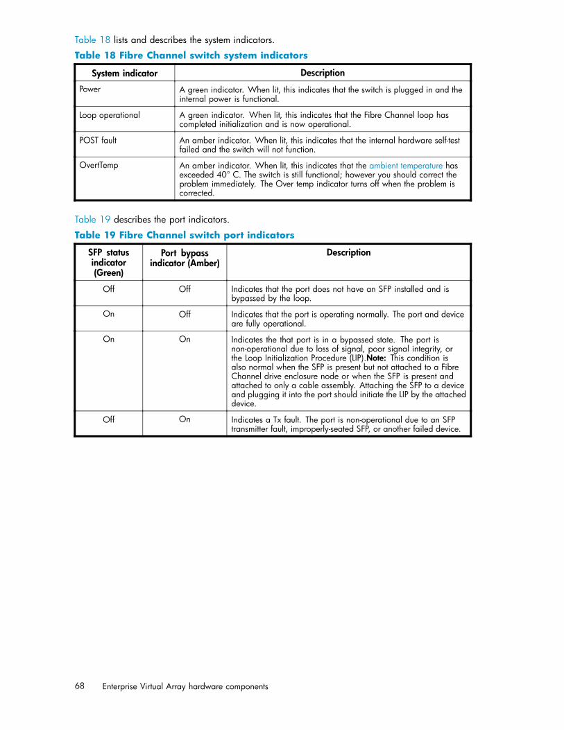
Table 18 lists and describes the system indicators.
Table 18 Fibre Channel switch system indicators
System indicator Description
Power A green indicator. When lit, this indicates that the switch is plugged in and theinternal power is functional.
Loop operational A green indicator. When lit, this indicates that the Fibre Channel loop hascompleted initialization and is now operational.
POST fault An amber indicator. When lit, this indicates that the internal hardware self-testfailed and the switch will not function.
OvertTemp An amber indicator. When lit, this indicates that the ambient temperature hasexceeded 40° C. The switch is still functional; however you should correct theproblem immediately. The Over temp indicator turns off when the problem iscorrected.
Table 19 describes the port indicators.
Table 19 Fibre Channel switch port indicators
SFP statusindicator(Green)
Port bypassindicator (Amber)
Description
Off Off Indicates that the port does not have an SFP installed and isbypassed by the loop.
On Off Indicates that the port is operating normally. The port and deviceare fully operational.
On On Indicates the that port is in a bypassed state. The port isnon-operational due to loss of signal, poor signal integrity, orthe Loop Initialization Procedure (LIP).Note: This condition isalso normal when the SFP is present but not attached to a FibreChannel drive enclosure node or when the SFP is present andattached to only a cable assembly. Attaching the SFP to a deviceand plugging it into the port should initiate the LIP by the attacheddevice.
Off On Indicates a Tx fault. The port is non-operational due to an SFPtransmitter fault, improperly-seated SFP, or another failed device.
68 Enterprise Virtual Array hardware components
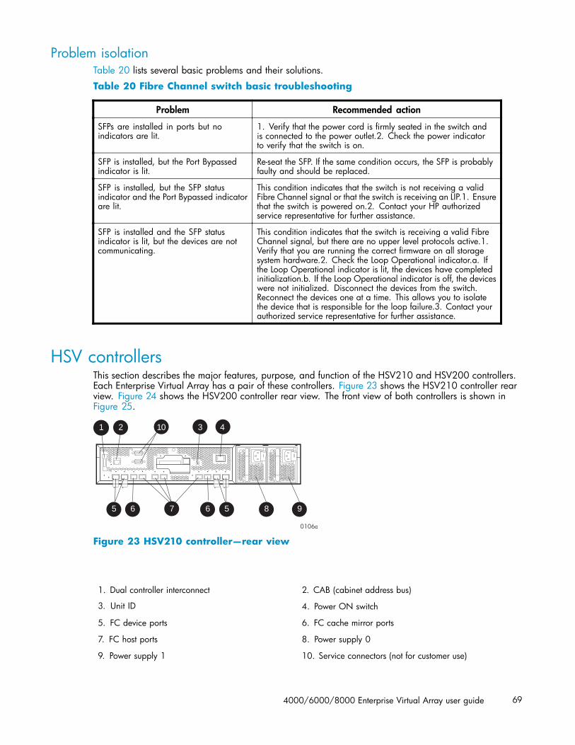
Problem isolationTable 20 lists several basic problems and their solutions.
Table 20 Fibre Channel switch basic troubleshooting
Problem Recommended action
SFPs are installed in ports but noindicators are lit.
1. Verify that the power cord is firmly seated in the switch andis connected to the power outlet.2. Check the power indicatorto verify that the switch is on.
SFP is installed, but the Port Bypassedindicator is lit.
Re-seat the SFP. If the same condition occurs, the SFP is probablyfaulty and should be replaced.
SFP is installed, but the SFP statusindicator and the Port Bypassed indicatorare lit.
This condition indicates that the switch is not receiving a validFibre Channel signal or that the switch is receiving an LIP.1. Ensurethat the switch is powered on.2. Contact your HP authorizedservice representative for further assistance.
SFP is installed and the SFP statusindicator is lit, but the devices are notcommunicating.
This condition indicates that the switch is receiving a valid FibreChannel signal, but there are no upper level protocols active.1.Verify that you are running the correct firmware on all storagesystem hardware.2. Check the Loop Operational indicator.a. Ifthe Loop Operational indicator is lit, the devices have completedinitialization.b. If the Loop Operational indicator is off, the deviceswere not initialized. Disconnect the devices from the switch.Reconnect the devices one at a time. This allows you to isolatethe device that is responsible for the loop failure.3. Contact yourauthorized service representative for further assistance.
HSV controllersThis section describes the major features, purpose, and function of the HSV210 and HSV200 controllers.Each Enterprise Virtual Array has a pair of these controllers. Figure 23 shows the HSV210 controller rearview. Figure 24 shows the HSV200 controller rear view. The front view of both controllers is shown inFigure 25.
1 2 3 4
85675 6
10
9
Figure 23 HSV210 controller—rear view
1. Dual controller interconnect 2. CAB (cabinet address bus)
3. Unit ID 4. Power ON switch
5. FC device ports 6. FC cache mirror ports
7. FC host ports 8. Power supply 0
9. Power supply 1 10. Service connectors (not for customer use)
4000/6000/8000 Enterprise Virtual Array user guide 69
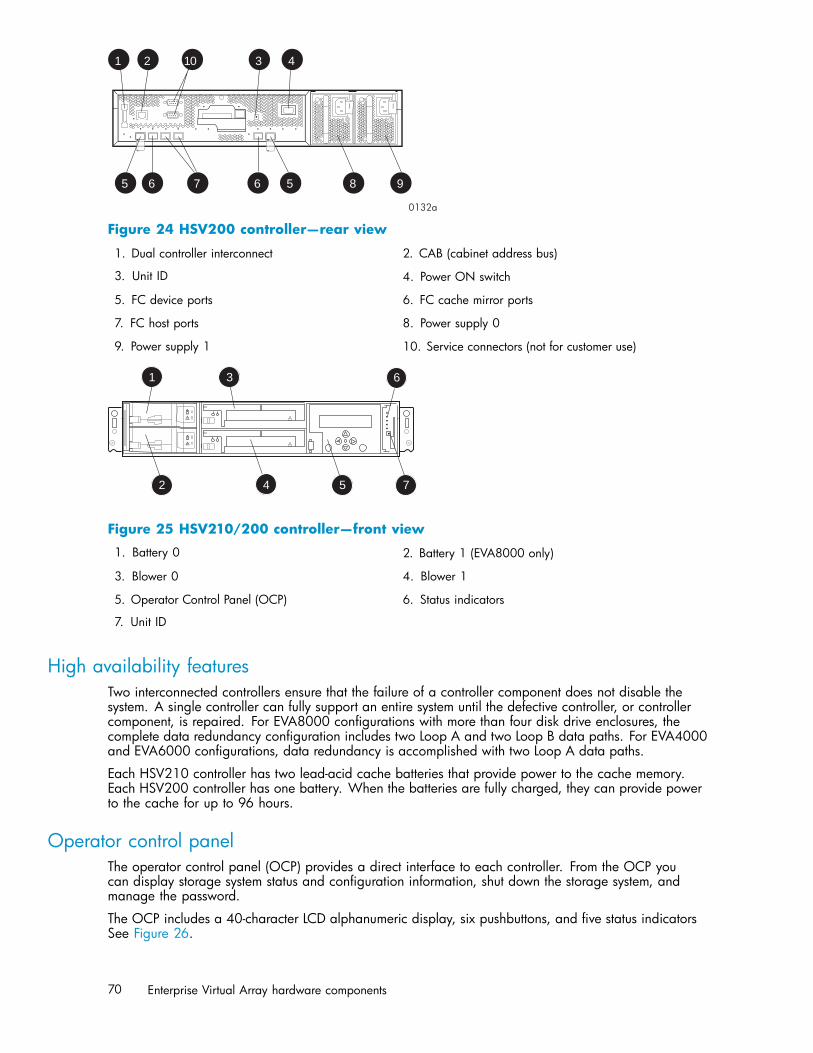
8 957 65 6
1 2 3 410
Figure 24 HSV200 controller—rear view
1. Dual controller interconnect 2. CAB (cabinet address bus)
3. Unit ID 4. Power ON switch
5. FC device ports 6. FC cache mirror ports
7. FC host ports 8. Power supply 0
9. Power supply 1 10. Service connectors (not for customer use)
1
2
3
4
6
5 7
6
4
Figure 25 HSV210/200 controller—front view
1. Battery 0 2. Battery 1 (EVA8000 only)
3. Blower 0 4. Blower 1
5. Operator Control Panel (OCP) 6. Status indicators
7. Unit ID
High availability featuresTwo interconnected controllers ensure that the failure of a controller component does not disable thesystem. A single controller can fully support an entire system until the defective controller, or controllercomponent, is repaired. For EVA8000 configurations with more than four disk drive enclosures, thecomplete data redundancy configuration includes two Loop A and two Loop B data paths. For EVA4000and EVA6000 configurations, data redundancy is accomplished with two Loop A data paths.
Each HSV210 controller has two lead-acid cache batteries that provide power to the cache memory.Each HSV200 controller has one battery. When the batteries are fully charged, they can provide powerto the cache for up to 96 hours.
Operator control panelThe operator control panel (OCP) provides a direct interface to each controller. From the OCP youcan display storage system status and configuration information, shut down the storage system, andmanage the password.
The OCP includes a 40-character LCD alphanumeric display, six pushbuttons, and five status indicatorsSee Figure 26.
70 Enterprise Virtual Array hardware components
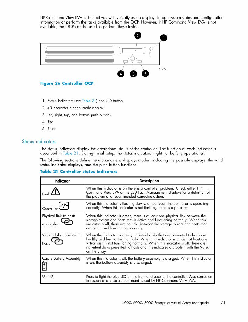
HP Command View EVA is the tool you will typically use to display storage system status and configurationinformation or perform the tasks available from the OCP. However, if HP Command View EVA is notavailable, the OCP can be used to perform these tasks.
0109b
12
4 3 5
Figure 26 Controller OCP
1. Status indicators (see Table 21) and UID button
2. 40–character alphanumeric display
3. Left, right, top, and bottom push buttons
4. Esc
5. Enter
Status indicatorsThe status indicators display the operational status of the controller. The function of each indicator isdescribed in Table 21. During initial setup, the status indicators might not be fully operational.
The following sections define the alphanumeric displays modes, including the possible displays, the validstatus indicator displays, and the push button functions.
Table 21 Controller status indicators
Indicator Description
FaultWhen this indicator is on there is a controller problem. Check either HPCommand View EVA or the LCD Fault Management displays for a definition ofthe problem and recommended corrective action.
ControllerWhen this indicator is flashing slowly, a heartbeat, the controller is operatingnormally. When this indicator is not flashing, there is a problem.
Physical link to hosts
established
When this indicator is green, there is at least one physical link between thestorage system and hosts that is active and functioning normally. When thisindicator is off, there are no links between the storage system and hosts thatare active and functioning normally.
Virtual disks presented to
hosts
When this indicator is green, all virtual disks that are presented to hosts arehealthy and functioning normally. When this indicator is amber, at least onevirtual disk is not functioning normally. When this indicator is off, there areno virtual disks presented to hosts and this indicates a problem with the Vdiskon the array.
Cache Battery Assembly When this indicator is off, the battery assembly is charged. When this indicatoris on, the battery assembly is discharged.
Unit ID Press to light the blue LED on the front and back of the controller. Also comes onin response to a Locate command issued by HP Command View EVA.
4000/6000/8000 Enterprise Virtual Array user guide 71

Each port on the rear of the controller has an associated status indicator located directly above it.Table 22 lists the port and its status description.
Table 22 Controller port status indicators
Port Description
Fibre Channel host ports • Green—Normal operation• Amber—No signal detected• Off—No SFP1detected or the Direct Connect OCP setting is incorrect
Fibre Channel device ports • Green—Normal operation• Amber—No signal detected or the controller has failed the port• Off—No SFP1 detected
Fibre Channel cache mirror ports • Green—Normal operation• Amber—No signal detected or the controller has failed the port• Off—No SFP1 detected
Dual controller interconnect port • Green—Normal operation• Amber—Interconnect cable not connected
1On copper Fibre Channel cables, the SFP is integrated into the cable connector.
Navigation buttonsThe operation of the navigation buttons is determined by the current display and location in the menustructure. Table 23 defines the basic push button functions when navigating the menus and options.
To simplify presentation and to avoid confusion, the push button reference names, regardless of labels,are left, right, top, and bottom.
Table 23 Navigation button functions
Button Function
Moves down through the available menus and options
Moves up through the available menus and options
Selects the displayed menu or option.
Returns to the previous menu.
Esc Used for “No” selections and to return to the default display.
Enter Used for “Yes” selections and to progress through menu items.
Alphanumeric displayThe alphanumeric display uses two LCD rows, each capable of displaying up to 20 alphanumericcharacters. By default, the alphanumeric display alternates between displaying the Storage System Nameand the World Wide Name. An active (flashing) display, an error condition message, or a user entry(pressing a push button) overrides the default display. When none of these conditions exist, the defaultdisplay returns after approximately 10 seconds.
Displaying the OCP menu treeThe Storage System Menu Tree lets you select information to be displayed, configuration settings tochange, or procedures to implement. To enter the menu tree, press any navigation push button whenthe default display is active.
The menu tree is organized into the following major menus:
72 Enterprise Virtual Array hardware components
• System Info—displays information and provides the ability to change various configurationsettings.
• Fault Management—displays fault information. Information about the Fault Management menuis included in Controller fault management.
• Shutdown Options—initiates the procedure for shutting down the system in a logical, sequentialmanner. Using the shutdown procedures maintains data integrity and avoids the possibility oflosing or corrupting data.
• System Password—create a system password to ensure that only authorized personnel canmanage the storage system using HP Command View EVA.
To enter and navigate the storage system menu tree:
1. Press any push button while the default display is in view. System Information becomes the activedisplay.
2. Press to sequence down through the menus.
Press to sequence up through the menus.
Press to select the displayed menu.
Press to return to the previous menu.
NOTE:To exit any menu, press Esc or wait ten seconds for the OCP display to return to the default display.
Table 24 identifies all the menu options available within the OCP display.
4000/6000/8000 Enterprise Virtual Array user guide 73
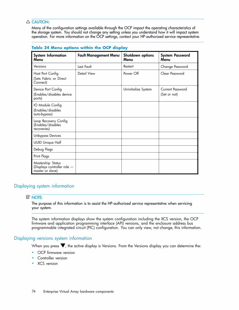
CAUTION:Many of the configuration settings available through the OCP impact the operating characteristics ofthe storage system. You should not change any setting unless you understand how it will impact systemoperation. For more information on the OCP settings, contact your HP-authorized service representative.
Table 24 Menu options within the OCP display
System InformationMenu
Fault Management Menu Shutdown optionsMenu
System PasswordMenu
Versions Last Fault Restart Change Password
Host Port Config(Sets Fabric or DirectConnect)
Detail View Power Off Clear Password
Device Port Config(Enables/disables deviceports)
Uninitialize System Current Password(Set or not)
IO Module Config(Enables/disablesauto-bypass)
Loop Recovery Config(Enables/disablesrecoveries)
Unbypass Devices
UUID Unique Half
Debug Flags
Print Flags
Mastership Status(Displays controller role —master or slave)
Displaying system information
NOTE:The purpose of this information is to assist the HP-authorized service representative when servicingyour system.
The system information displays show the system configuration including the XCS version, the OCPfirmware and application programming interface (API) versions, and the enclosure address busprogrammable integrated circuit (PIC) configuration. You can only view, not change, this information.
Displaying versions system informationWhen you press , the active display is Versions. From the Versions display you can determine the:
• OCP firmware version• Controller version• XCS version
74 Enterprise Virtual Array hardware components

NOTE:The terms PPC, Sprite, Glue, SDC, CBIC, and Atlantis are for development purposes and have nosignificance for normal operation.
NOTE:When viewing the software or firmware version information, pressing displays the Versions Menu tree.
To display System Information
1. The default display alternates between the Storage System Name display and the World WideName display.
Press any push button to select the Storage System Menu Tree display.
2. Press until the desired Versions Menu option appears, and then press or to move tosub–menu items per Table 24.
Shutting down the system
CAUTION:To power off the system for more than 96 hours, use HP Command View EVA.
You can use the Shutdown System function to implement the shutdown methods listed below. Theseshutdown methods are explained in Table 25.
• Shutting down the controller (see Shutting the controller down).• Restarting the system (see Restarting the System).• Uninitializing the system (see Uninitializing the System).
To ensure that you do not mistakenly activate a shutdown procedure, the default state is always NO,indicating do not implement this procedure. As a safeguard, implementing any shutdown methodrequires you to complete at least two actions.
Table 25 Shutdown methods
LCD prompt Description
Restart System? Implementing this procedure establishes communications between the storagesystem and HP Command View EVA. This procedure is used to restorethe controller to an operational state where it can communicate with HPCommand View EVA.
Power off system? Implementing this procedure initiates the sequential removal of controllerpower. This ensures no data is lost. The reasons for implementing thisprocedure include replacing a drive enclosure.
Uninitialize? Implementing this procedure will cause the loss of all data. For a detaileddiscussion of this procedure, see Uninitializing the System.
Shutting the controller downUse the following procedure to access the Shutdown System display and execute a shutdown procedure.
4000/6000/8000 Enterprise Virtual Array user guide 75

NOTE:HP Command View EVA is the preferred method for shutting down the controller. Shut down thecontroller from the OCP only if HP Command View EVA cannot communicate with the controller.Shutting down the controller from the OCP removes power from the controller on which the procedure isperformed only. To restore power, toggle the controller’s power switch.
CAUTION:If you decide NOT to power off while working in the Power Off menu, Power Off System NO must bedisplayed before you press Esc. This reduces the risk of accidentally powering down.
1. Press three times to scroll to the Shutdown Options menu.
2. Press to display Restart.
3. Press to scroll to Power Off.
4. Press to select Power Off.
5. Power off system is displayed. Press Enter to power off the system.
Restarting the systemTo restore the controller to an operational state, use the following procedure to restart the system.
1. Press three times to scroll to the Shutdown Options menu.
2. Press to select Restart.
3. Press to display Restart system?.
4. Press Enter to go to Startup.
No user input is required. The system will automatically initiate the startup procedure and proceed toload the Storage System Name and World Wide Name information from the operational controller.
Uninitializing the systemUninitializing the system is another way to shut down the system. This action causes the loss of all storagesystem data. Because HP Command View EVA cannot communicate with the disk drive enclosures,the stored data cannot be accessed.
CAUTION:Uninitializing the system destroys all user data. The WWN will remain in the controller unless bothcontrollers are powered off. The password will be lost. If the controllers remain powered on until youcreate another storage system (initialize via GUI), you will not have to re-enter the WWN.
Use the following procedure to uninitialize the system.
1. Press three times to scroll to the Shutdown Options menu.
2. Press to display Restart.
3. Press twice to display Uninitialize System.
4. Press to display Uninitialize?
5. Select Yes and press Enter. The system is now uninitialized.
76 Enterprise Virtual Array hardware components

Password optionsThe password entry options are:
• Entering a password during storage system initialization (see Setting up an HSV210-seriescontroller pair using the OCP).
• Showing the current password.• Changing a password (see Changing a password).• Removing password protection (see Clearing a password).
Changing a passwordFor security reasons, you may need to change a storage system password. Your password must containeight characters consisting of any combination of the uppercase letters A through Z and the lowercaseletters a through z.
Use the following procedure to change the password.
NOTE:Changing a system password on the controller requires changing the password on any HP CommandView EVA with access to the storage system.
1. Select a unique, eight-character password.
2. From the default menus (Storage System Name or World Wide Name) displayed, press threetimes to display System Password.
3. Press to display Change Password?
4. Press Enter for yes.
The default password, AAAAAAAA, is displayed.
5. Press or to select the first character.
6. Press to accept this character and select the next character.
7. Repeat the process to enter the remaining password characters.
8. Press Enter to enter the password and return to the default display.
Clearing a passwordUse the following procedure to remove storage system password protection.
NOTE:Changing a system password on the controller requires changing the password on any HP CommandView EVA with access to the storage system.
1. Press four times to scroll to the System Password menu.
2. Press to display Change Password?.
3. Press to scroll to Clear Password.
4. Press to display Clear Password.
5. Press Enter to clear the password.
The Password cleared message will be displayed.
4000/6000/8000 Enterprise Virtual Array user guide 77

Setting up a controller pair using the OCPFor information about how to set up a controller pair during initial installation see Setting Up a ControllerPair Using the OCP.
Power suppliesTwo power supplies provide the necessary operating voltages to all controller enclosure components. Ifone power supply fails, the remaining supply is capable of operating the enclosure.
Figure 27 Power supplies
1. Status indicator 2. Power supply 0
3. Power supply 1
Table 26 Power supply status indicators
Status indicator Description
Green Normal operation
Amber Power supply failure
Flashing amber The power cord is disconnected from the power supply
BlowersTwo blowers provide the cooling necessary to maintain the proper operating temperature within thecontroller enclosure. If one blower fails, the remaining blower is capable of cooling the enclosure.
78 Enterprise Virtual Array hardware components

Figure 28 Blower
1. Status indicator 2. Fault indicator
3. Blower 0 4. Blower 1
Table 27 Blower status indicators
Status indicator Fault indicator Description
On Off Normal operation
Off On Blower failure
Cache batteryBatteries provide backup power to maintain the contents of the controller cache when AC power is lostand the storage system has not been shutdown properly. When fully charged the batteries can sustain thecache contents for to 96 hours. Two batteries are used on the EVA8000 and a single battery is usedon the EVA6000 and EVA4000. cache batteries illustrates the location of the cache batteries and thebattery status indicators. Refer to Table 28 for additional information on the status indicators.
4000/6000/8000 Enterprise Virtual Array user guide 79
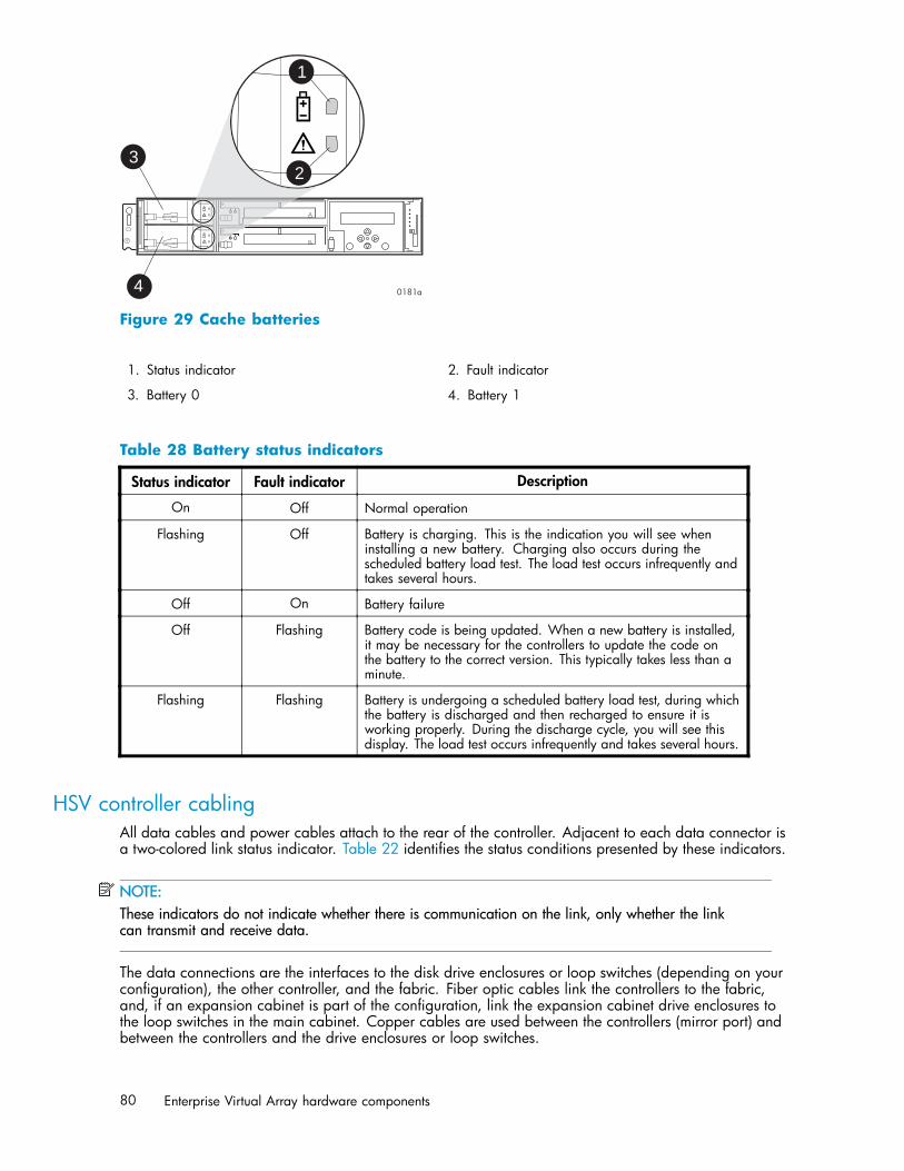
3
4
1
2
Figure 29 Cache batteries
1. Status indicator 2. Fault indicator
3. Battery 0 4. Battery 1
Table 28 Battery status indicators
Status indicator Fault indicator Description
On Off Normal operation
Flashing Off Battery is charging. This is the indication you will see wheninstalling a new battery. Charging also occurs during thescheduled battery load test. The load test occurs infrequently andtakes several hours.
Off On Battery failure
Off Flashing Battery code is being updated. When a new battery is installed,it may be necessary for the controllers to update the code onthe battery to the correct version. This typically takes less than aminute.
Flashing Flashing Battery is undergoing a scheduled battery load test, during whichthe battery is discharged and then recharged to ensure it isworking properly. During the discharge cycle, you will see thisdisplay. The load test occurs infrequently and takes several hours.
HSV controller cablingAll data cables and power cables attach to the rear of the controller. Adjacent to each data connector isa two-colored link status indicator. Table 22 identifies the status conditions presented by these indicators.
NOTE:These indicators do not indicate whether there is communication on the link, only whether the linkcan transmit and receive data.
The data connections are the interfaces to the disk drive enclosures or loop switches (depending on yourconfiguration), the other controller, and the fabric. Fiber optic cables link the controllers to the fabric,and, if an expansion cabinet is part of the configuration, link the expansion cabinet drive enclosures tothe loop switches in the main cabinet. Copper cables are used between the controllers (mirror port) andbetween the controllers and the drive enclosures or loop switches.
80 Enterprise Virtual Array hardware components

RacksEach rack has four feet and four casters. Raising the adjustable feet places the rack weight on the casters,so you can easily move the rack. Lowering the feet places the rack weight on the feet and prevents therack from moving. The removable front and rear doors, and the removable side panels provide easyaccess to the rack interior.
Each configuration has an upper and lower controller enclosure (the controller pair), drive enclosures,and an expansion bulkhead. Each controller pair and all the associated drive enclosures form a singlestorage system.
Rack configurationsEach system configuration depends on the following factors:
• The controller pair• The number of 3U Fibre Channel drive enclosures per rack
For more information about racks and configurations, including expansion and interconnection, refer tothe HP StorageWorks Enterprise Virtual Array hardware configuration guide.
Power distributionAC power is distributed to the rack through a dual Power Distribution Unit (PDU) assembly mounted at thebottom rear of the rack. The characteristics of the fully-redundant rack power configuration are as follows:
• Each PDU is connected to a separate circuit breaker-protected, 30–A AC site power source(220–240 VAC ±10%, 50 or 60–Hz, ±5%). Figure 30 illustrates the compatible 60–Hz and50–Hz wall receptacles.
CXO7549A
NEMA L6-30R receptacle, 3-wire, 30-A, 60-Hz
CXO5409B
IEC 309 receptacle, 3–wire, 30–A, 50–Hz
Figure 30 60–Hz and 50–Hz wall receptacles
• The standard power configuration for any Enterprise Virtual Array rack is the fully redundantconfiguration. Implementing this configuration requires:• Two separate circuit breaker-protected, 30–A site power sources with a compatible wall
receptacle (see Figure 30).• One dual PDU assembly. Each PDU connects to a different wall receptacle.• Six Power Distribution Modules (PDM) per rack. Three PDMs mount vertically on each side
of the rack. Each set of PDMs connects to a different PDU.• The drive enclosure power supplies on the left (PS 1) connect to the PDMs on the left with a
gray, 66 cm (26 in) power cord.• The drive enclosure power supplies on the right (PS 2) connect to the PDMs on the right with a
black, 66 cm (26 in) power cord.• The upper controller connects to a PDM on the left with a gray, 152 cm (60 in) power cord.• The lower controller connects to a PDM on the right with a black, 66 cm (26 in) power cord.
4000/6000/8000 Enterprise Virtual Array user guide 81

NOTE:Drive enclosures, when purchased separately, include one 50 cm black cable and one 50 cm gray cable.
The configuration provides complete power redundancy and eliminates all single points of failure forboth the AC and DC power distribution.
PDUsEach Enterprise Virtual Array rack has either a 50– or 60–Hz, dual PDU mounted at the bottom rearof the rack. The 228481–002/228481–003 PDU placement is back-to-back, plugs facing down, withswitches on top.
• The standard 50–Hz PDU cable has an IEC 309, 3–wire, 30–A, 50–Hz connector.• The standard 60–Hz PDU cable has a NEMA L6–30P, 3–wire, 30–A, 60–Hz connector.
If these connectors are not compatible with the site power distribution, you must replace the PDU powercord cable connector.
Each of the two PDU power cables has an AC power source specific connector. The circuitbreaker-controlled PDU outputs are routed to a group of four AC receptacles (see Figure 31). Thevoltages are then routed to PDMs, sometimes referred to as AC power strips, mounted on the two verticalrails in the rear of the rack.
1
0130a
2
3
5
4 5
Figure 31 Dual PDU assembly
1. PDU 1 2. PDU 2
3. Circuit breakers 4. AC receptacles
5. Mounting hardware
PDU 1
PDU 1 connects to AC power distribution source 1. A PDU 1 failure:
• Disables the power distribution circuit.• Removes power from PDMs 1, 2, and 3.• Disables PS 1 in the drive enclosures.• Disables the upper controller power supply.
PDU 2
PDU 2 connects to AC power distribution source 2. A PDU 2 failure:
• Disables the power distribution circuit.
82 Enterprise Virtual Array hardware components
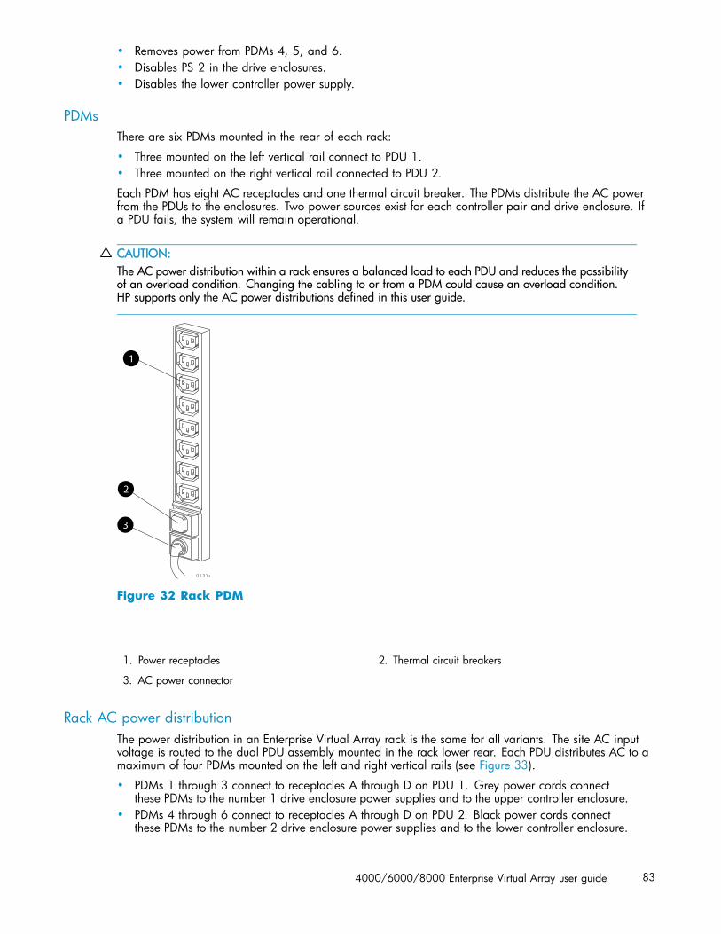
• Removes power from PDMs 4, 5, and 6.• Disables PS 2 in the drive enclosures.• Disables the lower controller power supply.
PDMsThere are six PDMs mounted in the rear of each rack:
• Three mounted on the left vertical rail connect to PDU 1.• Three mounted on the right vertical rail connected to PDU 2.
Each PDM has eight AC receptacles and one thermal circuit breaker. The PDMs distribute the AC powerfrom the PDUs to the enclosures. Two power sources exist for each controller pair and drive enclosure. Ifa PDU fails, the system will remain operational.
CAUTION:The AC power distribution within a rack ensures a balanced load to each PDU and reduces the possibilityof an overload condition. Changing the cabling to or from a PDM could cause an overload condition.HP supports only the AC power distributions defined in this user guide.
0131a
1
2
3
Figure 32 Rack PDM
1. Power receptacles 2. Thermal circuit breakers
3. AC power connector
Rack AC power distributionThe power distribution in an Enterprise Virtual Array rack is the same for all variants. The site AC inputvoltage is routed to the dual PDU assembly mounted in the rack lower rear. Each PDU distributes AC to amaximum of four PDMs mounted on the left and right vertical rails (see Figure 33).
• PDMs 1 through 3 connect to receptacles A through D on PDU 1. Grey power cords connectthese PDMs to the number 1 drive enclosure power supplies and to the upper controller enclosure.
• PDMs 4 through 6 connect to receptacles A through D on PDU 2. Black power cords connectthese PDMs to the number 2 drive enclosure power supplies and to the lower controller enclosure.
4000/6000/8000 Enterprise Virtual Array user guide 83

NOTE:The locations of the PDUs and the PDMs are the same in all racks.
Figure 33 Rack AC power distribution
1. PDM 1 2. PDM 2
3. PDM 3 4. PDU 1
5. PDM 4 6. PDM 5
7. PDM 6 8. PDU 2
Rack System/E power distribution componentsAC power is distributed to the Rack System/E rack through Power Distribution Units (PDU) mounted on thetwo vertical rails in the rear of the rack. Up to four PDUs can be mounted in the rack—two mountedon the right side of the cabinet and two mounted on the left side.
Each of the PDU power cables has an AC power source specific connector. The circuit breaker-controlledPDU outputs are routed to a group of ten AC receptacles. The storage system components plug directlyinto the PDUs.
Rack AC power distribution
The power distribution configuration in a Rack System/E rack depends on the number of storage systemsinstalled in the rack. If one storage system is installed, only two PDUs are required. If multiple storagesystems are installed, four PDUs are required.
The site AC input voltage is routed to each PDU mounted in the rack. Each PDU distributes AC throughten receptacles directly to the storage system components.
• PDUs 1 and 3 (optional) are mounted on the left side of the cabinet. Grey power cords connectthese PDUs to the number 1 drive enclosure power supplies and to the controller enclosures.
• PDUs 2 and 4 (optional) are mounted on the right side of the cabinet. Black power cords connectthese PDUs to the number 2 drive enclosure power supplies and to the controller enclosures.
84 Enterprise Virtual Array hardware components
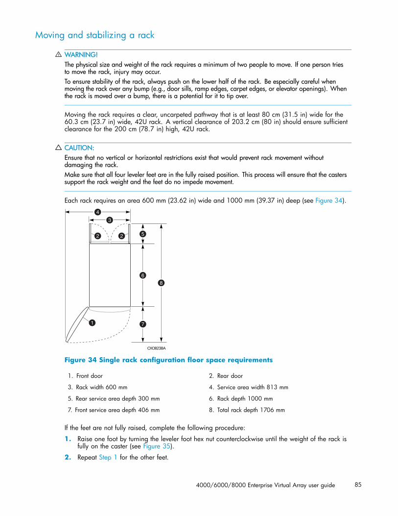
Moving and stabilizing a rack
WARNING!The physical size and weight of the rack requires a minimum of two people to move. If one person triesto move the rack, injury may occur.To ensure stability of the rack, always push on the lower half of the rack. Be especially careful whenmoving the rack over any bump (e.g., door sills, ramp edges, carpet edges, or elevator openings). Whenthe rack is moved over a bump, there is a potential for it to tip over.
Moving the rack requires a clear, uncarpeted pathway that is at least 80 cm (31.5 in) wide for the60.3 cm (23.7 in) wide, 42U rack. A vertical clearance of 203.2 cm (80 in) should ensure sufficientclearance for the 200 cm (78.7 in) high, 42U rack.
CAUTION:Ensure that no vertical or horizontal restrictions exist that would prevent rack movement withoutdamaging the rack.Make sure that all four leveler feet are in the fully raised position. This process will ensure that the casterssupport the rack weight and the feet do no impede movement.
Each rack requires an area 600 mm (23.62 in) wide and 1000 mm (39.37 in) deep (see Figure 34).
CXO8238A
1
3
2
4
5
6
7
8
2
Figure 34 Single rack configuration floor space requirements
1. Front door 2. Rear door
3. Rack width 600 mm 4. Service area width 813 mm
5. Rear service area depth 300 mm 6. Rack depth 1000 mm
7. Front service area depth 406 mm 8. Total rack depth 1706 mm
If the feet are not fully raised, complete the following procedure:
1. Raise one foot by turning the leveler foot hex nut counterclockwise until the weight of the rack isfully on the caster (see Figure 35).
2. Repeat Step 1 for the other feet.
4000/6000/8000 Enterprise Virtual Array user guide 85
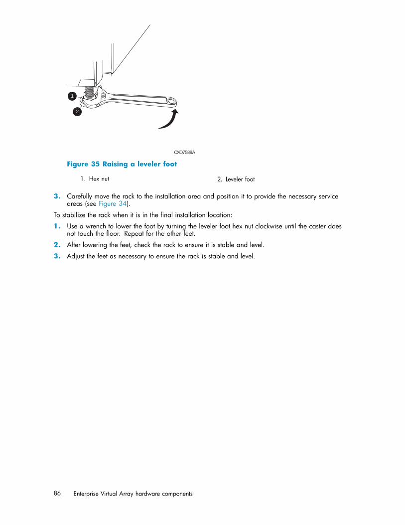
2
CXO7589A
1
Figure 35 Raising a leveler foot
1. Hex nut 2. Leveler foot
3. Carefully move the rack to the installation area and position it to provide the necessary serviceareas (see Figure 34).
To stabilize the rack when it is in the final installation location:
1. Use a wrench to lower the foot by turning the leveler foot hex nut clockwise until the caster doesnot touch the floor. Repeat for the other feet.
2. After lowering the feet, check the rack to ensure it is stable and level.
3. Adjust the feet as necessary to ensure the rack is stable and level.
86 Enterprise Virtual Array hardware components

5 Customer replaceable units
This chapter describes the procedures for replacing CRUs. Information about initial enclosure installation,ESD protection, and common replacement procedures is also presented.
Customer self repair (CSR)HP’s customer self-repair program offers you fast, easy service. It enables HP to deliver replacementcomponents directly to you so that you can replace them at your own convenience.
• The WEBES fault management and diagnostics tool has been designed to identify many of theEVA4000/6000/8000 component failures that may qualify for customer self repair.
• Using WEBES, ISEE or other diagnostic tools, a support specialist will work with you to diagnoseand assess whether a replacement component is required to address a system problem. Thespecialist will also determine whether you can perform the replacement.
• If you have a Same Business Day (SBD) entitlement (including 2–hour or 4–hour response), CSRcomponents can be delivered for replacement as geography and local part stocking permits.
• Replacement instructions are included in this user guide, in spare kits and at hp.com. If furtherassistance is required, you can call the HP Technical Support Center and a technician will helpyou over the phone.
• Make sure you return the failed component to HP using the instructions included with thereplacement part.
• CSR is available for most HP products currently under warranty. For more information on warrantyservice go to: http://h18006.www1.hp.com/products/storageworks/warranty.html.
Table 29 identifies which EVA 4000/6000/8000 hardware components are customer replaceable.
Best practices for replacing hardware componentsThe following information will help you replace the hardware components on your storage systemsuccessfully. Follow these tips any time you must replace a component.
CAUTION:Removing a component significantly changes the air flow within the enclosure. All components must beinstalled for the enclosure to cool properly. If a component fails, leave it in place in the enclosure until anew component is available to install.
Verifying component failure• Make sure you confer with HP technical support to verify that the hardware component has failed
and that you are authorized to replace it yourself.• Additional hardware failures can complicate component replacement. Check HP StorageWorks
Command View EVA and/or the WEBES System Event Analyzer as follows to detect anyadditional hardware problems:• When you have confirmed that a component replacement is required, you may want to clear
the Real Time Monitoring view. This makes it easier to identify additional hardware problemsthat may occur while waiting for the replacement part.
• Before installing the replacement part, check the Real Time Monitoring view for any newhardware problems. If additional hardware problems have occurred, contact HP supportbefore replacing the component.
4000/6000/8000 Enterprise Virtual Array user guide 87
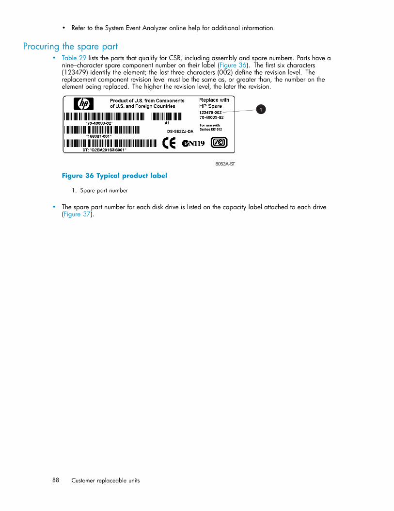
• Refer to the System Event Analyzer online help for additional information.
Procuring the spare part• Table 29 lists the parts that qualify for CSR, including assembly and spare numbers. Parts have a
nine–character spare component number on their label (Figure 36). The first six characters(123479) identify the element; the last three characters (002) define the revision level. Thereplacement component revision level must be the same as, or greater than, the number on theelement being replaced. The higher the revision level, the later the revision.
8053A-ST
1
Figure 36 Typical product label
1. Spare part number
• The spare part number for each disk drive is listed on the capacity label attached to each drive(Figure 37).
88 Customer replaceable units

Figure 37 Disk drive label
Table 29 Hardware component CSR support
Part description Assembly part number Spare part number CSR
Cache battery 30-10013-01 348879-001(30-10013-S1)
Recommended
Controller blower 12-10008-01 390852-001(12-10008-S1)
Recommended
Controller power supply 339596-001 349800-001 Recommended1
Disk enclosure blower 70-40085-01 123482-001(70-40085–S1)
Recommended1
Disk enclosure powersupply
30-50872-XXXX=01, 02,03, 12, 13
212398-001(30-50872-S1 or -S2)
Recommended1
Disk drive – 300 GB 10K 365608-001 366023-001 Recommended
Disk drive – 250 GB FATA 365606-001 366022-001 Recommended
Disk drive – 146 GB 10K 293557-001 300590-001 Recommended
Disk drive – 146 GB 15K 365610-001 366024-001 Recommended
Disk drive – 72 GB 10K 238926-001 244448-001 Recommended
Disk drive – 72 GB 15K 293569-001 300588-001 Recommended
Operator control panel 70-41143-01 390859-001(70-41143-S1)
EMU 70-40145-02 375393-001(70-40145-S2)
FC I/O module A 70-40616-03 364549-001(70-40616-S4)
FC I/O module B 70-40615-03 364548-001(70-40615-S4)
2GB SFP Transceiver 212192-002 229204-001
Controller EVA8000 70-41138-01 390855-001(70-41138-S1)
Controller EVA6000/4000
70-41138-02 390856-001(70-41138-S2)
Front panel bezelEVA8000
70-41140-01 390853-001(70-41140-S1)
Recommended
Front panel bezelEVA6000/4000
70-41140-02 390854-001(70-41140-S2)
Recommended
1 Always use caution to avoid damage to cabling when replacing this component.
4000/6000/8000 Enterprise Virtual Array user guide 89

Replacing the failed component
CAUTION:Components can be damaged by electrostatic discharge. Use proper anti-static protection as discussedbelow..• Always transport and store CRUs in an ESD protective enclosure.• Do not remove the CRU from the ESD protective enclosure until you are ready to install it.• Always use ESD precautions, such as a wrist strap, heel straps on conductive flooring, and an ESD
protective smock when handling ESD sensitive equipment.• Avoid touching the CRU connector pins, leads, or circuitry.• Do not place ESD generating material such as paper or non anti-static (pink) plastic in an ESD
protective enclosure with ESD sensitive equipment.
• HP recommends waiting until periods of low storage system activity to replace a component.• When replacing components at the backend of the rack, cabling may obstruct access to the
component. Carefully move any cables out of the way to avoid loosening any connections. Inparticular, avoid cable damage that may be caused by:• Kinking or bending.• Disconnecting cables without capping. If uncapped, cable performance may be impaired by
contact with dust, metal or other surfaces.• Placing removed cables on the floor or other surfaces, where they may be walked on or
otherwise compressed.• Replacement procedures are provided with each component. You can also download the
replacement instructions in Dutch, English, French, German, Italian, Spanish and Japanese fromthe following web sites:• http://www.hp.com/go/eva4000• http://www.hp.com/go/eva6000• http://www.hp.com/go/eva8000From any of these web sites, select Technical documents under Product information for additionalinformation.
Returning the defective part• HP specifies, in the materials shipped with a replacement CSR part, whether the defective
component must be returned to HP. Where required, you must ship the defective component backto HP within a defined period of time, normally five (5) business days. The defective componentmust be returned with the associated documentation provided in the shipping material. Failureto return the defective component may result in HP billing you for the replacement. With acustomer self repair, HP will pay all shipping and component return costs and determine thecourier/carrier to be used.
Replacing the cache batteryThis section describes the procedure for replacing the cache battery used in Enterprise Virtual Array(EVA) products.
90 Customer replaceable units

NOTE:There are two cache batteries installed in the EVA8000 controller enclosure in slots 0 and 1 at the leftend of the enclosure. There is only one battery in the EVA4000 and EVA6000 controller installedin the upper slot (0).
Before you beginObserve the following precautions when replacing a battery.
CAUTION:Parts can be damaged by electrostatic discharge. Use proper anti-static protection. Refer to thedocumentation that shipped with your system for additional information.Use two hands when removing a battery to ensure you do not drop it.Have a copy of the product User Guide available for reference. You can download a copy of the userguide from the product support page on the HP web site.
Verifying component failureBefore replacing a battery, use the following methods to verify the component failure:
CAUTION:If Command View EVA does not present a status consistent with that of the battery status indicator, or ifCommand View or the System Event Analyzer indicates multiple hardware failures, contact HP supportfor assistance. The HP support web site is located at http://www.hp.com/support
• Analyze any failure messages you may have received from system monitoring (System EventAnalyzer).
• Check status using Command View EVA:
CAUTION:If you are running HP StorageWorks Command View EVA 4.0, the battery numbering presented inthe management interface is inconsistent with the numbering used in the storage system and reportedby the ISEE/WEBES monitoring tool. HP Command View EVA 4.0 identifies the top battery as 1and the bottom battery as 2. The correct numbering should be 0 and 1 respectively. Remember tomake this conversion when replacing a battery. This inconsistency is corrected in later versionsof HP Command View EVA.
1. In the Navigation pane, select Storage system > Hardware > Rack > Controller enclosure >Controller.
2. In the Content pane, select the Enclosure tab. The status is displayed in the Cache BatteryModules field. The status should be Failed .
3. To help identify the correct enclosure, click Locate > Locate On to display Locate Confirmedon the controller operator control panel (OCP). The blue Unit ID indicator will also turn on.
• Check the battery status indicators. See Figure 38. The battery fault indicator should be on. Toview the status indicators it is necessary to remove the front panel as described in Removinga blower.
4000/6000/8000 Enterprise Virtual Array user guide 91
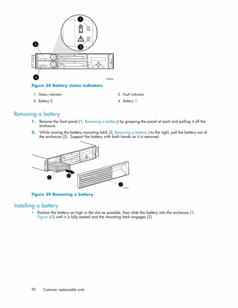
Figure 38 Battery status indicators
1. Status indicator 2. Fault indicator
3. Battery 0 4. Battery 1
Removing a battery1. Remove the front panel (1, Removing a battery) by grasping the panel at each end pulling it off the
enclosure.
2. While moving the battery mounting latch (2, Removing a battery ) to the right, pull the battery out ofthe enclosure (3). Support the battery with both hands as it is removed.
3
1
2
0180a
Figure 39 Removing a battery
Installing a battery• Position the battery as high in the slot as possible, then slide the battery into the enclosure (1,
Figure 40) until it is fully seated and the mounting latch engages (2).
92 Customer replaceable units

Figure 40 Installing a battery
Verifying proper operationAfter replacing the battery, check the following to verify that the component is operating properly:
NOTE:It may take up to 10 minutes for the component to display good status.
• Check the battery status indicators. See Table 28• During the first minute, both status indicators may be on or flashing.• The status indicator (1) should then begin flashing, indicating the battery is charging. It
may take several hours for a new battery to fully charge. The fault indicator (2) should beoff during charging.
After checking the status indicator, install the front panel on the enclosure by pressing it firmlyinto place.
• From Command View EVA• Navigate back to the component and check the status. It should be .• Turn off the locate function by clicking Locate > Locate Off
Replacing a controller blowerThis section describes the procedure for replacing the blower used in Enterprise Virtual Array (EVA)products.
Before you beginObserve the following precautions when replacing a blower.
CAUTION:Removing a blower significantly changes the air flow within the enclosure. Both blowers must be installedfor the enclosure to cool properly. If a blowers fails, leave it in place in the enclosure until a new bloweris available to install.Parts can be damaged by electrostatic discharge. Use proper anti-static protection. Refer to thedocumentation that shipped with your system for additional information.Have a copy of the product User Guide available for reference. You can download a copy of the UserGuide from the product support page on the HP web site.
Verifying component failureBefore replacing a blower, use the following methods to verify the component failure:
4000/6000/8000 Enterprise Virtual Array user guide 93

CAUTION:If Command View EVA does not present a status consistent with that of the blower status indicators, or ifCommand View or the System Event Analyzer indicates multiple hardware failures, contact HP supportfor assistance. The HP support web site is located at http://www.hp.com/support
• Analyze any failure messages you may have received from system monitoring (System EventAnalyzer).
• Check status using Command View EVA:
CAUTION:If you are running HP StorageWorks Command View EVA 4.0, the blower numbering presented inthe management interface is inconsistent with the numbering used in the storage system and reportedby the ISEE/WEBES monitoring tool. HP Command View EVA 4.0 identifies the top blower as 1and the bottom blower as 2. The correct numbering should be 0 and 1 respectively. Remember tomake this conversion when replacing a blower. This inconsistency is corrected in later versionsof HP Command View EVA.
1. In the Navigation pane, select Storage system > Hardware > Rack > Controller enclosure >Controller
2. In the Content pane, select the Enclosure tab. The status is displayed in the Cooling Systemfield. The status should be Failed .
3. To help identify the correct enclosure, click Locate > Locate On to display Locate Confirmedon the controller operator control panel (OCP). The blue Unit ID indicator will also turn on.
• Check the blower status indicators. See Figure 41. The fault indicator (2) should be on. To viewthe status indicators it may be necessary to remove the front panel as described in Removinga blower.
Figure 41 Blower status indicators
1. Status indicator 2. Fault indicator
3. Blower 0 4. Blower 1
Removing a blower
WARNING!The blower motor does not stop immediately when the blower is removed. Keep your fingers away fromthe blower blades until the motor stops.
94 Customer replaceable units
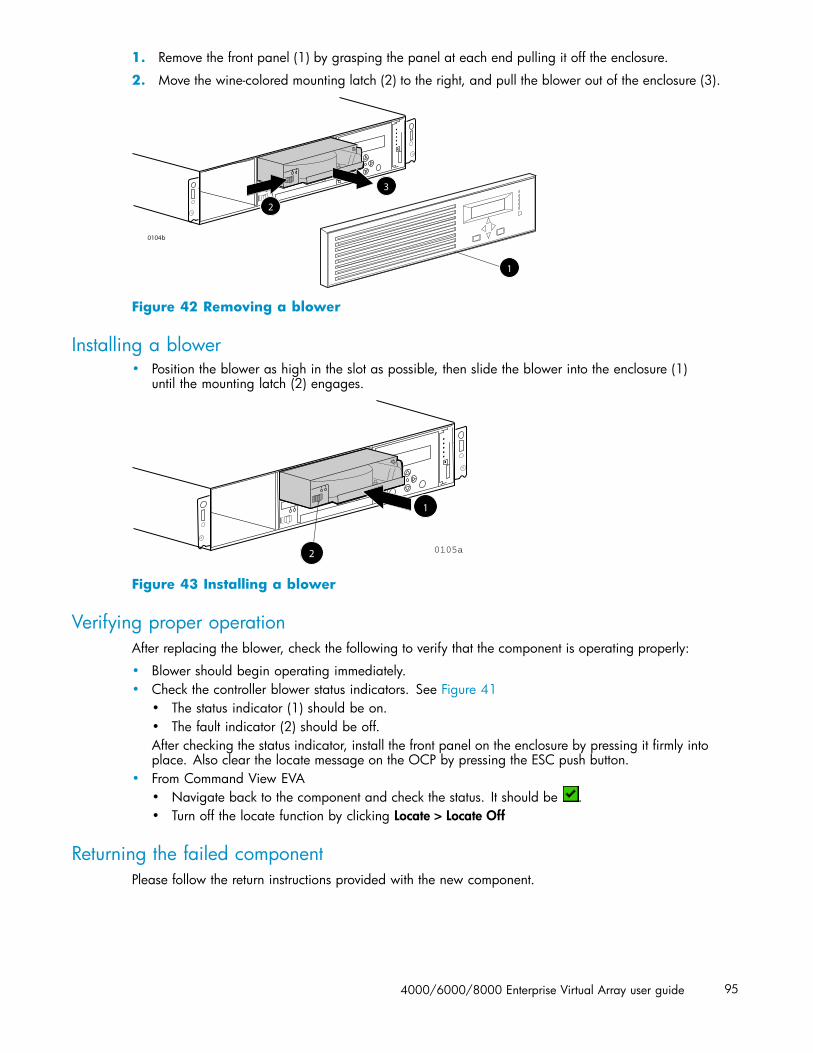
1. Remove the front panel (1) by grasping the panel at each end pulling it off the enclosure.
2. Move the wine-colored mounting latch (2) to the right, and pull the blower out of the enclosure (3).
0104b
2
3
1
Figure 42 Removing a blower
Installing a blower• Position the blower as high in the slot as possible, then slide the blower into the enclosure (1)
until the mounting latch (2) engages.
2
1
0105a
Figure 43 Installing a blower
Verifying proper operationAfter replacing the blower, check the following to verify that the component is operating properly:
• Blower should begin operating immediately.• Check the controller blower status indicators. See Figure 41
• The status indicator (1) should be on.• The fault indicator (2) should be off.After checking the status indicator, install the front panel on the enclosure by pressing it firmly intoplace. Also clear the locate message on the OCP by pressing the ESC push button.
• From Command View EVA• Navigate back to the component and check the status. It should be .• Turn off the locate function by clicking Locate > Locate Off
Returning the failed componentPlease follow the return instructions provided with the new component.
4000/6000/8000 Enterprise Virtual Array user guide 95

Replacing the controller power supplyThis section describes the procedure for replacing the power supply used in EVA 4000/6000/8000products.
NOTE:Because this component is used in several products, the drawings may reflect a different enclosure thanthe one you have. The removal and replacement procedure is the same for each product.
Before you beginObserve the following precautions when replacing a power supply.
CAUTION:Removing a power supply significantly changes the air flow within the enclosure. Both power suppliesmust be installed for the enclosure to cool properly. If a power supply fails, leave it in place in theenclosure until a new power supply is available to install.If cabling is obstructing access to the power supply, carefully move the cables out of the way to avoidloosening any connections.Parts can be damaged by electrostatic discharge. Use proper anti-static protection. Refer to thedocumentation that shipped with your system for additional information.Have a copy of the product User Guide available for reference. You can download a copy of the UserGuide from the product support page on the HP web site.
Verifying component failureBefore replacing a power supply, use the following methods to verify the component failure.
CAUTION:If Command View EVA does not present a status consistent with that of the power supply status indicator,or if Command View or the System Event Analyzer indicates multiple hardware failures, contact HPsupport for assistance. The HP support web site is located at http://www.hp.com/support
• Analyze any failure messages you may have received from system monitoring (System EventAnalyzer).
• Check status using Command View EVA:
CAUTION:If you are running HP StorageWorks Command View EVA 4.0, the power supply numberingpresented in the management interface is inconsistent with the numbering used in the storage systemand reported by the ISEE/WEBES monitoring tool. HP Command View EVA 4.0 identifies the leftpower supply as 1 and the right power supply as 2. The correct numbering should be 0 and 1respectively. Remember to make this conversion when replacing a power supply. This inconsistency iscorrected in later versions of HP Command View EVA.
1. In the Navigation pane, select Storage system > Hardware > Rack > Controller enclosure >Controller
2. In the Content pane, select the Enclosure tab. The status is displayed in the Power System field.The status should be Failed .
96 Customer replaceable units
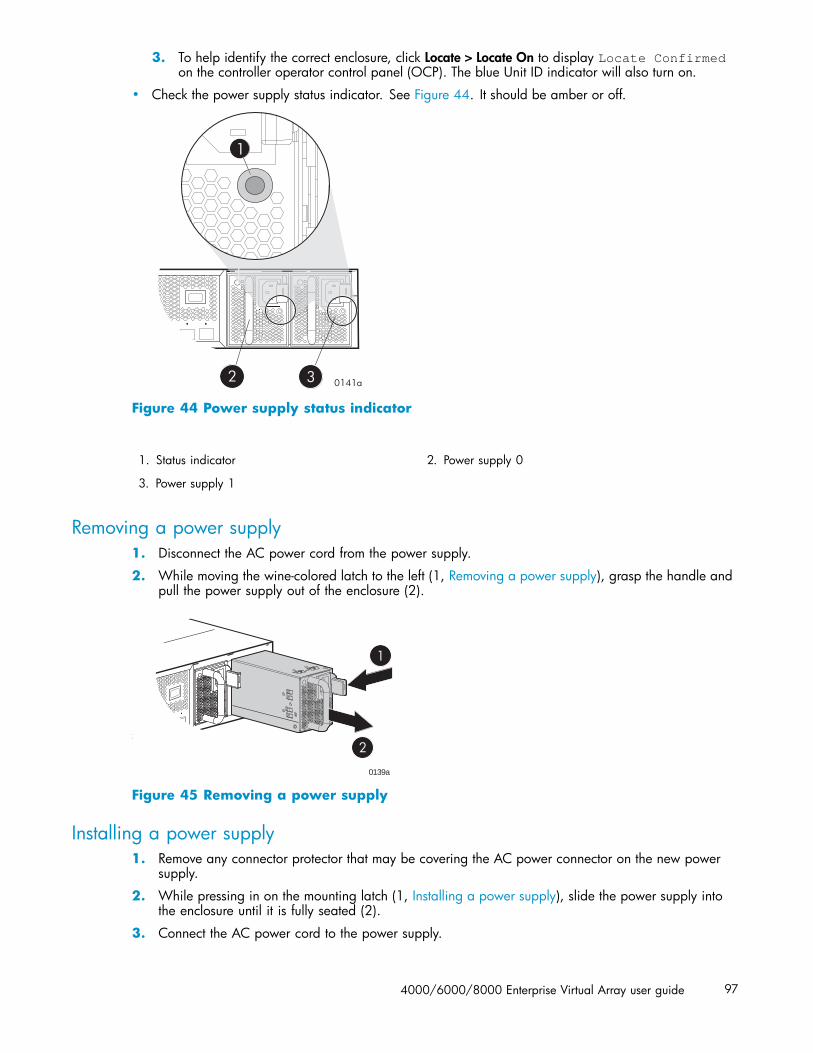
3. To help identify the correct enclosure, click Locate > Locate On to display Locate Confirmedon the controller operator control panel (OCP). The blue Unit ID indicator will also turn on.
• Check the power supply status indicator. See Figure 44. It should be amber or off.
Figure 44 Power supply status indicator
1. Status indicator 2. Power supply 0
3. Power supply 1
Removing a power supply1. Disconnect the AC power cord from the power supply.
2. While moving the wine-colored latch to the left (1, Removing a power supply), grasp the handle andpull the power supply out of the enclosure (2).
0139a
Figure 45 Removing a power supply
Installing a power supply1. Remove any connector protector that may be covering the AC power connector on the new power
supply.
2. While pressing in on the mounting latch (1, Installing a power supply), slide the power supply intothe enclosure until it is fully seated (2).
3. Connect the AC power cord to the power supply.
4000/6000/8000 Enterprise Virtual Array user guide 97
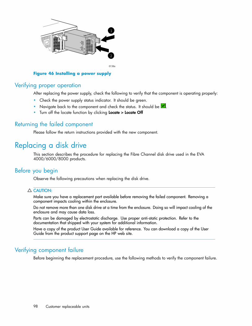
1
2
0138a
Figure 46 Installing a power supply
Verifying proper operationAfter replacing the power supply, check the following to verify that the component is operating properly:
• Check the power supply status indicator. It should be green.• Navigate back to the component and check the status. It should be .• Turn off the locate function by clicking Locate > Locate Off
Returning the failed componentPlease follow the return instructions provided with the new component.
Replacing a disk driveThis section describes the procedure for replacing the Fibre Channel disk drive used in the EVA4000/6000/8000 products.
Before you beginObserve the following precautions when replacing the disk drive.
CAUTION:Make sure you have a replacement part available before removing the failed component. Removing acomponent impacts cooling within the enclosure.Do not remove more than one disk drive at a time from the enclosure. Doing so will impact cooling of theenclosure and may cause data loss.Parts can be damaged by electrostatic discharge. Use proper anti-static protection. Refer to thedocumentation that shipped with your system for additional information.Have a copy of the product User Guide available for reference. You can download a copy of the UserGuide from the product support page on the HP web site.
Verifying component failureBefore beginning the replacement procedure, use the following methods to verify the component failure.
98 Customer replaceable units
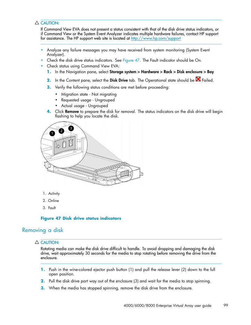
CAUTION:If Command View EVA does not present a status consistent with that of the disk drive status indicators, orif Command View or the System Event Analyzer indicates multiple hardware failures, contact HP supportfor assistance. The HP support web site is located at http://www.hp.com/support
• Analyze any failure messages you may have received from system monitoring (System EventAnalyzer).
• Check the disk drive status indicators. See Figure 47. The Fault indicator should be On.• Check status using Command View EVA:
1. In the Navigation pane, select Storage system > Hardware > Rack > Disk enclosure > Bay
2. In the Content pane, select the Disk Drive tab. The Operational state should be Failed.
3. Verify the following status conditions are met before proceeding:
• Migration state - Not migrating• Requested usage - Ungrouped• Actual usage - Ungrouped
4. Click Remove to prepare the disk for removal. The status indicators on the disk drive will beginflashing to help you locate the disk.
1. Activity
2. Online
3. Fault
Figure 47 Disk drive status indicators
Removing a disk
CAUTION:Rotating media can make the disk drive difficult to handle. To avoid dropping and damaging the diskdrive, wait approximately 30 seconds for the media to stop rotating before removing the drive from theenclosure.
1. Push in the wine-colored ejector push button (1) and pull the release lever (2) down to the fullopen position.
2. Pull the disk drive part way out of the enclosure (3) and wait for the media to stop spinning.
3. When the media has stopped spinning, remove the disk drive from the enclosure.
4000/6000/8000 Enterprise Virtual Array user guide 99
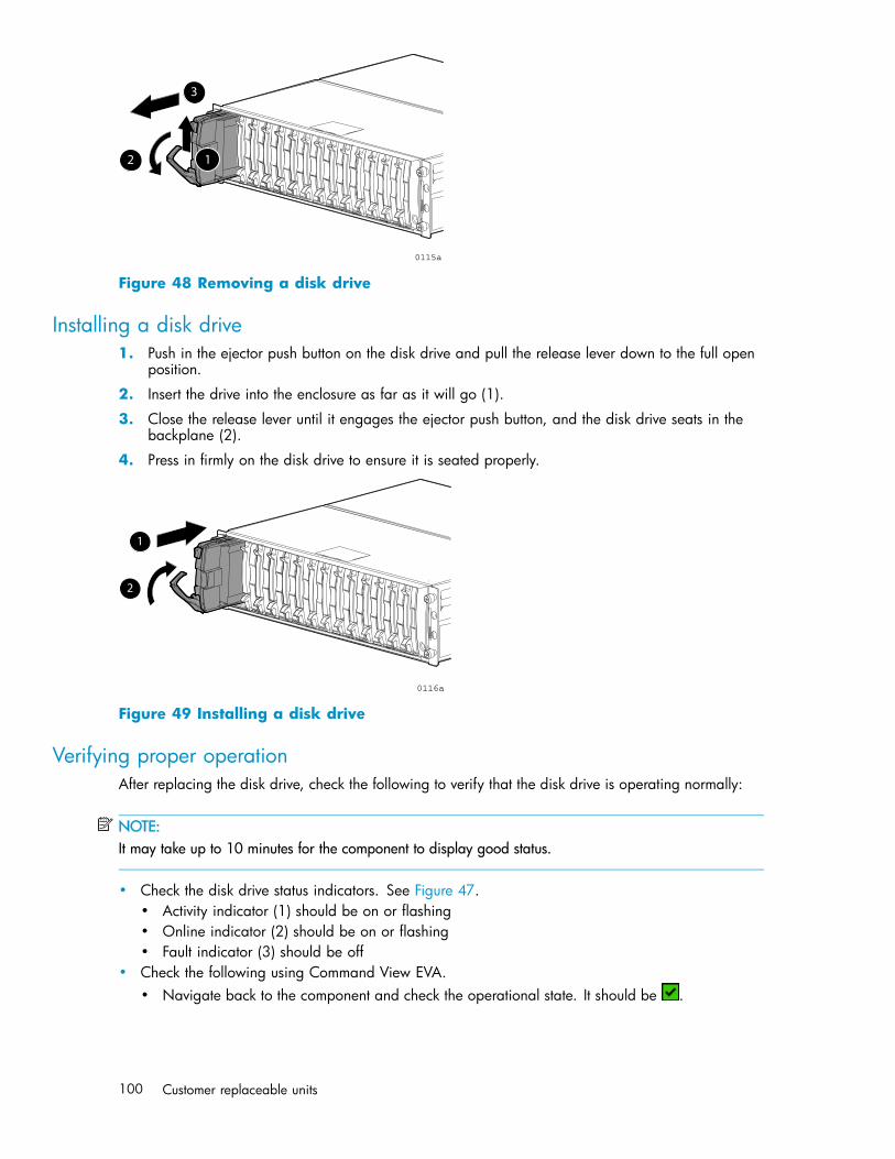
0115a
3
2 1
Figure 48 Removing a disk drive
Installing a disk drive1. Push in the ejector push button on the disk drive and pull the release lever down to the full open
position.
2. Insert the drive into the enclosure as far as it will go (1).
3. Close the release lever until it engages the ejector push button, and the disk drive seats in thebackplane (2).
4. Press in firmly on the disk drive to ensure it is seated properly.
0116a
2
1
Figure 49 Installing a disk drive
Verifying proper operationAfter replacing the disk drive, check the following to verify that the disk drive is operating normally:
NOTE:It may take up to 10 minutes for the component to display good status.
• Check the disk drive status indicators. See Figure 47.• Activity indicator (1) should be on or flashing• Online indicator (2) should be on or flashing• Fault indicator (3) should be off
• Check the following using Command View EVA.• Navigate back to the component and check the operational state. It should be .
100 Customer replaceable units
• Ensure the disk drive is using the correct firmware. Check the Firmware Version againstthe supported disk firmware in the HP StorageWorks Enterprise Virtual Array release notes.The most current edition of the release notes can be downloaded from the following website:http://www.hp.com/go/eva8000If the disk drive is using an unsupported version of firmware, contact HP support for assistance.Do not add the disk drive to a disk group if it using an unsupported firmware version.
Adding a disk to the groupAfter replacing the disk, it should be added to a disk group. The disk is typically added back intoits original disk group.
1. In the Navigation pane, select Storage system > Hardware > Rack > Disk enclosure > Bay
2. In the Content pane, select the Disk Drive tab.
3. Click Group to initiate the process for adding the disk to a disk group.
NOTE:If the Device Addition Policy is set to automatic, the disk will automatically be added to a disk group. Inthis case the Group option will not be available.
Returning the failed componentPlease follow the return instructions provided with the new component.
Replacing the disk enclosure power supply/blowerThis section describes the procedure for replacing the power supply/blower assembly used in EVA4000/6000/8000 products.
NOTE:Because this component is used in several products, the drawings may reflect a different enclosure thanthe one you have. The removal and replacement procedure is the same for each product.
Before you beginObserve the following precautions when replacing the power supply/blower.
CAUTION:You have only seven minutes to perform the replacement procedure! Both power supplies must beinstalled for the enclosure to cool properly. If a power supply fails, leave it in place in the enclosure untila new power supply is available to install. The enclosure could shut down due to overheating unless thepower supply is replaced within seven minutes of removal of the failed/failing power supply.If cabling is obstructing access to the power supply/blower, carefully move the cables out of the wayto avoid loosening any connections.Parts can be damaged by electrostatic discharge. Use proper anti-static protection. Refer to thedocumentation that shipped with your system for additional information.Have a copy of the product User Guide available for reference. You can download a copy of the UserGuide from the product support page on the HP web site.
4000/6000/8000 Enterprise Virtual Array user guide 101
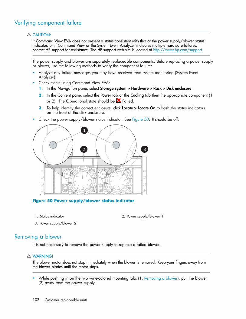
Verifying component failure
CAUTION:If Command View EVA does not present a status consistent with that of the power supply/blower statusindicator, or if Command View or the System Event Analyzer indicates multiple hardware failures,contact HP support for assistance. The HP support web site is located at http://www.hp.com/support
The power supply and blower are separately replaceable components. Before replacing a power supplyor blower, use the following methods to verify the component failure:
• Analyze any failure messages you may have received from system monitoring (System EventAnalyzer).
• Check status using Command View EVA:1. In the Navigation pane, select Storage system > Hardware > Rack > Disk enclosure
2. In the Content pane, select the Power tab or the Cooling tab then the appropriate component (1or 2). The Operational state should be Failed.
3. To help identify the correct enclosure, click Locate > Locate On to flash the status indicatorson the front of the disk enclosure.
• Check the power supply/blower status indicator. See Figure 50. It should be off.
1
2 3
Figure 50 Power supply/blower status indicator
1. Status indicator 2. Power supply/blower 1
3. Power supply/blower 2
Removing a blowerIt is not necessary to remove the power supply to replace a failed blower.
WARNING!The blower motor does not stop immediately when the blower is removed. Keep your fingers away fromthe blower blades until the motor stops.
• While pushing in on the two wine-colored mounting tabs (1, Removing a blower), pull the blower(2) away from the power supply.
102 Customer replaceable units

Figure 51 Removing a blower
Installing a blower
CAUTION:Pressing on the center section of the blower can damage the blades or the housing. Only press onthe outer edge of the blower when installing it.
1. Align the blower guide post (2, Installing a blower) with the mounting hole next to the powersupply connector (1).
2. Slide the blower onto the power supply (4) until the mounting tabs (3) snap into place.
Figure 52 Installing a blower
Removing a power supply
CAUTION:When a power supply is removed, the enclosure could shut down within seven minutes due to overheatingunless the power supply is replaced.
1. Disengage the power cord lock (1, Figure 53) and disconnect the power cord from the power supply.
CAUTION:When removing the left power supply, ensure the cord lock on the right power supply isengaged. This will avoid inadvertently disconnecting the right power supply. Also take careto avoid disrupting the cables on the I/O module to left of the power supply.
2. Lift up on the wine-colored mounting latch (2), then grasp the blower (3) and pull the power supplyout of the enclosure.
3. Remove the blower from the defective power supply and install it on the replacement power supply.
4000/6000/8000 Enterprise Virtual Array user guide 103
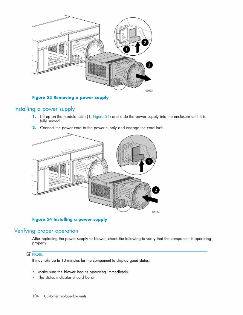
Figure 53 Removing a power supply
Installing a power supply1. Lift up on the module latch (1, Figure 54) and slide the power supply into the enclosure until it is
fully seated.
2. Connect the power cord to the power supply and engage the cord lock.
Figure 54 Installing a power supply
Verifying proper operationAfter replacing the power supply or blower, check the following to verify that the component is operatingproperly:
NOTE:It may take up to 10 minutes for the component to display good status.
• Make sure the blower begins operating immediately.• The status indicator should be on.
104 Customer replaceable units
• From Command View EVA• Navigate back to the component and check the status. It should be
.• Turn off the locate function by clicking Locate > Locate Off
Returning the failed componentPlease follow the return instructions provided with the new component.
4000/6000/8000 Enterprise Virtual Array user guide 105

106 Customer replaceable units

A Regulatory notices andspecifications
This appendix includes regulatory notices and product specifications for the HP StorageWorks EnterpriseVirtual Array family.
The following topics are included:
• Regulatory notices• Fibre Channel drive enclosure specifications• Fibre Channel switch specifications• Controller specifications• Rack specifications
Regulatory notices
Federal Communications Commission (FCC) noticePart 15 of the Federal Communications Commission (FCC) Rules and Regulations has established RadioFrequency (RF) emission limits to provide an interference-free radio frequency spectrum. Many electronicdevices, including computers, generate RF energy incidental to their intended function and are, therefore,covered by these rules. These rules place computers and related peripheral devices into two classes, Aand B, depending upon their intended installation. Class A devices are those that may reasonably beexpected to be installed in a business or commercial environment. Class B devices are those that mayreasonably be expected to be installed in a residential environment (for example, personal computers).The FCC requires devices in both classes to bear a label indicating the interference potential of the deviceas well as additional operating instructions for the user.
The rating label on the device shows the classification (A or B) of the equipment. Class B devices have anFCC logo or FCC ID on the label. Class A devices do not have an FCC logo or FCC ID on the label.After the class of the device is determined, refer to the corresponding statement in the following sections.
FCC Class A certificationThis equipment generates, uses, and may emit radio frequency energy. The equipment has been typetested and found to comply with the limits for a Class A digital device pursuant to Part 15 of the FCCrules, which are designed to provide reasonable protection against such radio frequency interference.
Operation of this equipment in a residential area may cause interference, in which case the user at theuser’s own expense will be required to take whatever measures may be required to correct the interference.
Any modifications to this device—unless approved by the manufacturer—can void the user’s authority tooperate this equipment under Part 15 of the FCC rules.
NOTE:Additional information on the need to interconnect the device with shielded (data) cables or the need forspecial devices, such as ferrite beads on cables, is required if such means of interference suppressionwas used in the qualification test for the device. This information will vary from device to device andneeds to be obtained from the HP EMC group.
4000/6000/8000 Enterprise Virtual Array user guide 107

Class A equipmentThis equipment has been tested and found to comply with the limits for a Class A digital device, pursuantto Part 15 of the FCC Rules. These limits are designed to provide reasonable protection against harmfulinterference when the equipment is operated in a commercial environment. This equipment generates,uses, and can radiate radio frequency energy and, if not installed and used in accordance with theinstructions, may cause harmful interference to radio communications. Operation of this equipment in aresidential area is likely to cause harmful interference, in which case the user will be required to correctthe interference at personal expense.
Class B equipmentThis equipment has been tested and found to comply with the limits for a Class B digital device, pursuantto Part 15 of the FCC Rules. These limits are designed to provide reasonable protection against harmfulinterference in a residential installation. This equipment generates, uses, and can radiate radio frequencyenergy and, if not installed and used in accordance with the instructions, may cause harmful interferenceto radio communications. However, there is no guarantee that interference will not occur in a particularinstallation. If this equipment does cause harmful interference to radio or television reception, whichcan be determined by turning the equipment off and on, the user is encouraged to try to correct theinterference by one or more of the following measures:
• Reorient or relocate the receiving antenna.• Increase the separation between the equipment and receiver.• Connect the equipment into an outlet on a circuit that is different from that to which the receiver is
connected.• Consult the dealer or an experienced radio or television technician for help.
Declaration of conformity for products marked with the FCC logo, United States onlyThis device complies with Part 15 of the FCC Rules. Operation is subject to the following two conditions:(1) this device may not cause harmful interference, and (2) this device must accept any interferencereceived, including interference that may cause undesired operation.
For questions regarding your product, refer to http://thenew.hp.com.
For questions regarding this FCC declaration, contact:
• Hewlett-Packard CompanyProduct Regulations Manager3000 Hanover St.Palo Alto, CA 94304• Or call 1-650-857-1501
To identify this product, refer to the part, series, or model number found on the product.
ModificationsThe FCC requires the user to be notified that any changes or modifications made to this device that are notexpressly approved by Hewlett-Packard Company may void the user’s authority to operate the equipment.
CablesConnections to this device must be made with shielded cables with metallic RFI/EMI connector hoodsin order to maintain compliance with FCC Rules and Regulations.
Laser deviceAll Hewlett-Packard systems equipped with a laser device comply with safety standards, includingInternational Electrotechnical Commission (IEC) 825. With specific regard to the laser, the equipmentcomplies with laser product performance standards set by government agencies as a Class 1 laserproduct. The product does not emit hazardous light; the beam is totally enclosed during all modes ofcustomer operation and maintenance.
108 Regulatory notices and specifications

Laser safety warningsHeed the following warning:
WARNING!WARNING: To reduce the risk of exposure to hazardous radiation:• Do not try to open the laser device enclosure. There are no user-serviceable components inside.• Do not operate controls, make adjustments, or perform procedures to the laser device other thanthose specified herein.• Allow only HP authorized service technicians to repair the laser device.
Compliance with CDRH regulationsThe Center for Devices and Radiological Health (CDRH) of the U.S. Food and Drug Administrationimplemented regulations for laser products on August 2, 1976. These regulations apply to laser productsmanufactured from August 1, 1976. Compliance is mandatory for products marketed in the United States.
Certification and classification informationThis product contains a laser internal to the Optical Link Module (OLM) for connection to the Fibrecommunications port.
In the USA, the OLM is certified as a Class 1 laser product conforming to the requirements contained inthe Department of Health and Human Services (DHHS) regulation 21 CFR, Subchapter J. The certificationis indicated by a label on the plastic OLM housing.
Outside the USA, the OLM is certified as a Class 1 laser product conforming to the requirementscontained in IEC 825-1:1993 and EN 60825-1:1994, including Amendment 11:1996.
The OLM includes the following certifications:
• UL Recognized Component (USA)• CSA Certified Component (Canada)• TUV Certified Component (European Union)• CB Certificate (Worldwide)
Canadien notice (avis Canadien)
Class A equipmentThis Class A digital apparatus meets all requirements of the Canadian Interference-Causing EquipmentRegulations.
Cet appareil numérique de la classe A respecte toutes les exigences du Règlement sur le matérielbrouilleur du Canada.
Class B equipmentThis Class B digital apparatus meets all requirements of the Canadian Interference-Causing EquipmentRegulations.
Cet appareil numérique de la classe B respecte toutes les exigences du Règlement sur le matérielbrouilleur du Canada.
4000/6000/8000 Enterprise Virtual Array user guide 109
European union noticeProducts with the CE Marking comply with both the EMC Directive (89/336/EEC) and the Low VoltageDirective (73/23/EEC) issued by the Commission of the European Community.
Compliance with these directives implies conformity to the following European Norms (the equivalentinternational standards are in parenthesis):
• EN55022 (CISPR 22) - Electromagnetic Interference• EN55024 (IEC61000-4-2, 3, 4, 5, 6, 8, 11) - Electromagnetic Immunity• EN61000-3-2 (IEC61000-3-2) - Power Line Harmonics• EN61000-3-3 (IEC61000-3-3) - Power Line Flicker• EN60950 (IEC950) - Product Safety
Notice for FranceDECLARATION D’INSTALLATION ET DE MISE EN EXPLOITATION d’un matériel de traitement del’information (ATI), classé A en fonction des niveaux de perturbations radioélectriques émis, définis dansla norme européenne EN 55022 concernant la Compatibilité Electromagnétique.
WEEE Recycling Notices
English noticeDisposal of waste equipment by users in private household in the European Union
This symbol on the product or on its packaging indicates that this product must not be disposed ofwith your other household waste. Instead, it is your responsibility to dispose of your waste equipmentby handing it over to a designated collection point for recycling of waste electrical and electronicequipment. The separate collection and recycling of your waste equipment at the time of disposal willhelp to conserve natural resources and ensure that it is recycled in a manner that protects human healthand the environment. For more information about where you can drop off your waste equipment forrecycling, please contact your local city office, your household waste disposal service, or the shop whereyou purchased the product.
Dutch noticeVerwijdering van afgedankte apparatuur door privé-gebruikers in de Europese Unie
Dit symbool op het product of de verpakking geeft aan dat dit product niet mag wordengedeponeerd bij het normale huishoudelijke afval. U bent zelf verantwoordelijk voor het inleveren van uwafgedankte apparatuur bij een inzamelingspunt voor het recyclen van oude elektrische en elektronischeapparatuur. Door uw oude apparatuur apart aan te bieden en te recyclen, kunnen natuurlijke bronnenworden behouden en kan het materiaal worden hergebruikt op een manier waarmee de volksgezondheiden het milieu worden beschermd. Neem contact op met uw gemeente, het afvalinzamelingsbedrijf ofde winkel waar u het product hebt gekocht voor meer informatie over inzamelingspunten waar u oudeapparatuur kunt aanbieden voor recycling.
Czechoslovakian noticeLikvidace zařízení soukromými domácími uživateli v Evropské unii
110 Regulatory notices and specifications

Tento symbol na produktu nebo balení označuje výrobek, který nesmí být vyhozen spolu s ostatnímdomácím odpadem. Povinností uživatele je předat takto označený odpad na předem určené sběrnémísto pro recyklaci elektrických a elektronických zařízení. Okamžité třídění a recyklace odpadu pomůžeuchovat přírodní prostředí a zajistí takový způsob recyklace, který ochrání zdraví a životní prostředíčlověka. Další informace o možnostech odevzdání odpadu k recyklaci získáte na příslušném obecnímnebo městském úřadě, od firmy zabývající se sběrem a svozem odpadu nebo v obchodě, kde jsteprodukt zakoupili.
Estonian noticeSeadmete jäätmete kõrvaldamine eramajapidamistes Euroopa Liidus
See tootel või selle pakendil olev sümbol näitab, et kõnealust toodet ei tohi koos teistemajapidamisjäätmetega kõrvaldada. Teie kohus on oma seadmete jäätmed kõrvaldada, viies needelektri- ja elektroonikaseadmete jäätmete ringlussevõtmiseks selleks ettenähtud kogumispunkti. Seadmetejäätmete eraldi kogumine ja ringlussevõtmine kõrvaldamise ajal aitab kaitsta loodusvarasid ning tagada,et ringlussevõtmine toimub viisil, mis kaitseb inimeste tervist ning keskkonda. Lisateabe saamiseksselle kohta, kuhu oma seadmete jäätmed ringlussevõtmiseks viia, võtke palun ühendust oma kohalikulinnakantselei, majapidamisjäätmete kõrvaldamise teenistuse või kauplusega, kust Te toote ostsite.
Finnish noticeLaitteiden hävittäminen kotitalouksissa Euroopan unionin alueella
Jos tuotteessa tai sen pakkauksessa on tämä merkki, tuotetta ei saa hävittää kotitalousjätteidenmukana. Tällöin hävitettävä laite on toimitettava sähkölaitteiden ja elektronisten laitteidenkierrätyspisteeseen. Hävitettävien laitteiden erillinen käsittely ja kierrätys auttavat säästämäänluonnonvaroja ja varmistamaan, että laite kierrätetään tavalla, joka estää terveyshaitat ja suojeleeluontoa. Lisätietoja paikoista, joihin hävitettävät laitteet voi toimittaa kierrätettäväksi, saa ottamallayhteyttä jätehuoltoon tai liikkeeseen, josta tuote on ostettu.
French noticeÉlimination des appareils mis au rebut par les ménages dans l’Union européenne
Le symbole apposé sur ce produit ou sur son emballage indique que ce produit ne doit pas êtrejeté avec les déchets ménagers ordinaires. Il est de votre responsabilité de mettre au rebut vos appareilsen les déposant dans les centres de collecte publique désignés pour le recyclage des équipementsélectriques et électroniques. La collecte et le recyclage de vos appareils mis au rebut indépendamment dureste des déchets contribue à la préservation des ressources naturelles et garantit que ces appareils serontrecyclés dans le respect de la santé humaine et de l’environnement. Pour obtenir plus d’informationssur les centres de collecte et de recyclage des appareils mis au rebut, veuillez contacter les autoritéslocales de votre région, les services de collecte des ordures ménagères ou le magasin dans lequelvous avez acheté ce produit.
German noticeEntsorgung von Altgeräten aus privaten Haushalten in der EU
4000/6000/8000 Enterprise Virtual Array user guide 111

Das Symbol auf dem Produkt oder seiner Verpackung weist darauf hin, dass das Produktnicht über den normalen Hausmüll entsorgt werden darf. Benutzer sind verpflichtet, die Altgerätean einer Rücknahmestelle für Elektro- und Elektronik-Altgeräte abzugeben. Die getrennte Sammlungund ordnungsgemäße Entsorgung Ihrer Altgeräte trägt zur Erhaltung der natürlichen Ressourcenbei und garantiert eine Wiederverwertung, die die Gesundheit des Menschen und die Umweltschützt. Informationen dazu, wo Sie Rücknahmestellen für Ihre Altgeräte finden, erhalten Sie bei IhrerStadtverwaltung, den örtlichen Müllentsorgungsbetrieben oder im Geschäft, in dem Sie das Geräterworben haben.
Greek noticeΑπόρριψη άχρηστου εξοπλισμού από χρήστες σε ιδιωτικά νοικοκυριά στην Ευρωπαϊκή Ένωση
Το σύμβολο αυτό στο προϊόν ή τη συσκευασία του υποδεικνύει ότι το συγκεκριμένο προϊόν δενπρέπει να διατίθεται μαζί με τα άλλα οικιακά σας απορρίμματα. Αντίθετα, είναι δική σας ευθύνη νααπορρίψετε τον άχρηστο εξοπλισμό σας παραδίδοντάς τον σε καθορισμένο σημείο συλλογής για τηνανακύκλωση άχρηστου ηλεκτρικού και ηλεκτρονικού εξοπλισμού. Η ξεχωριστή συλλογή και ανακύκλωσητου άχρηστου εξοπλισμού σας κατά την απόρριψη θα συμβάλει στη διατήρηση των φυσικών πόρων και θαδιασφαλίσει ότι η ανακύκλωση γίνεται με τρόπο που προστατεύει την ανθρώπινη υγεία και το περιβάλλον.Για περισσότερες πληροφορίες σχετικά με το πού μπορείτε να παραδώσετε τον άχρηστο εξοπλισμό σαςγια ανακύκλωση, επικοινωνήστε με το αρμόδιο τοπικό γραφείο, την τοπική υπηρεσία διάθεσης οικιακώναπορριμμάτων ή το κατάστημα όπου αγοράσατε το προϊόν.
Hungarian noticeKészülékek magánháztartásban történő selejtezése az Európai Unió területén
A készüléken, illetve a készülék csomagolásán látható azonos szimbólum annak jelzésére szolgál,hogy a készülék a selejtezés során az egyéb háztartási hulladéktól eltérő módon kezelendő. A vásárlóa hulladékká vált készüléket köteles a kijelölt gyűjtőhelyre szállítani az elektromos és elektronikaikészülékek újrahasznosítása céljából. A hulladékká vált készülékek selejtezéskori begyűjtése ésújrahasznosítása hozzájárul a természeti erőforrások megőrzéséhez, valamint biztosítja a selejtezetttermékek környezetre és emberi egészségre nézve biztonságos feldolgozását. A begyűjtés pontoshelyéről bővebb tájékoztatást a lakhelye szerint illetékes önkormányzattól, az illetékes szemételtakarítóvállalattól, illetve a terméket elárusító helyen kaphat.
Italian noticeSmaltimento delle apparecchiature da parte di privati nel territorio dell’Unione Europea
Questo simbolo presente sul prodotto o sulla sua confezione indica che il prodotto non puòessere smaltito insieme ai rifiuti domestici. È responsabilità dell’utente smaltire le apparecchiatureconsegnandole presso un punto di raccolta designato al riciclo e allo smaltimento di apparecchiatureelettriche ed elettroniche. La raccolta differenziata e il corretto riciclo delle apparecchiature da smaltirepermette di proteggere la salute degli individui e l’ecosistema. Per ulteriori informazioni relative aipunti di raccolta delle apparecchiature, contattare l’ente locale per lo smaltimento dei rifiuti, oppure ilnegozio presso il quale è stato acquistato il prodotto.
112 Regulatory notices and specifications
Latvian noticeNolietotu iekārtu iznīcināšanas noteikumi lietotājiem Eiropas Savienības privātajās mājsaimniecībās
Šāds simbols uz izstrādājuma vai uz tā iesaiņojuma norāda, ka šo izstrādājumu nedrīkst izmestkopā ar citiem sadzīves atkritumiem. Jūs atbildat par to, lai nolietotās iekārtas tiktu nodotas speciāliiekārtotos punktos, kas paredzēti izmantoto elektrisko un elektronisko iekārtu savākšanai otrreizējaipārstrādei. Atsevišķa nolietoto iekārtu savākšana un otrreizējā pārstrāde palīdzēs saglabāt dabasresursus un garantēs, ka šīs iekārtas tiks otrreizēji pārstrādātas tādā veidā, lai pasargātu vidi un cilvēkuveselību. Lai uzzinātu, kur nolietotās iekārtas var izmest otrreizējai pārstrādei, jāvēršas savas dzīvesvietas pašvaldībā, sadzīves atkritumu savākšanas dienestā vai veikalā, kurā izstrādājums tika nopirkts.
Lithuanian noticeVartotojų iš privačių namų ūkių įrangos atliekų šalinimas Europos Sąjungoje
Šis simbolis ant gaminio arba jo pakuotės rodo, kad šio gaminio šalinti kartu su kitomis namųūkio atliekomis negalima. Šalintinas įrangos atliekas privalote pristatyti į specialią surinkimo vietąelektros ir elektroninės įrangos atliekoms perdirbti. Atskirai surenkamos ir perdirbamos šalintinos įrangosatliekos padės saugoti gamtinius išteklius ir užtikrinti, kad jos bus perdirbtos tokiu būdu, kuris nekenkiažmonių sveikatai ir aplinkai. Jeigu norite sužinoti daugiau apie tai, kur galima pristatyti perdirbtinasįrangos atliekas, kreipkitės į savo seniūniją, namų ūkio atliekų šalinimo tarnybą arba parduotuvę, kuriojeįsigijote gaminį.
Polish noticePozbywanie się zużytego sprzętu przez użytkowników w prywatnych gospodarstwach domowych wUnii Europejskiej
Ten symbol na produkcie lub jego opakowaniu oznacza, że produktu nie wolno wyrzucać dozwykłych pojemników na śmieci. Obowiązkiem użytkownika jest przekazanie zużytego sprzętu dowyznaczonego punktu zbiórki w celu recyklingu odpadów powstałych ze sprzętu elektrycznego ielektronicznego. Osobna zbiórka oraz recykling zużytego sprzętu pomogą w ochronie zasobównaturalnych i zapewnią ponowne wprowadzenie go do obiegu w sposób chroniący zdrowie człowieka iśrodowisko. Aby uzyskać więcej informacji o tym, gdzie można przekazać zużyty sprzęt do recyklingu,należy się skontaktować z urzędem miasta, zakładem gospodarki odpadami lub sklepem, w którymzakupiono produkt.
Portuguese noticeDescarte de Lixo Elétrico na Comunidade Européia
Este símbolo encontrado no produto ou na embalagem indica que o produto não deve serdescartado no lixo doméstico comum. É responsabilidade do cliente descartar o material usado (lixoelétrico), encaminhando-o para um ponto de coleta para reciclagem. A coleta e a reciclagem seletivasdesse tipo de lixo ajudarão a conservar as reservas naturais; sendo assim, a reciclagem será feita deuma forma segura, protegendo o ambiente e a saúde das pessoas. Para obter mais informações sobrelocais que reciclam esse tipo de material, entre em contato com o escritório da HP em sua cidade, com oserviço de coleta de lixo ou com a loja em que o produto foi adquirido.
4000/6000/8000 Enterprise Virtual Array user guide 113
Slovakian noticeLikvidácia vyradených zariadení v domácnostiach v Európskej únii
Symbol na výrobku alebo jeho balení označuje, že daný výrobok sa nesmie likvidovať s domovýmodpadom. Povinnosťou spotrebiteľa je odovzdať vyradené zariadenie v zbernom mieste, ktoré jeurčené na recykláciu vyradených elektrických a elektronických zariadení. Separovaný zber a recykláciavyradených zariadení prispieva k ochrane prírodných zdrojov a zabezpečuje, že recyklácia sa vykonávaspôsobom chrániacim ľudské zdravie a životné prostredie. Informácie o zberných miestach na recykláciuvyradených zariadení vám poskytne miestne zastupiteľstvo, spoločnosť zabezpečujúca odvoz domovéhoodpadu alebo obchod, v ktorom ste si výrobok zakúpili.
Slovenian noticeOdstranjevanje odslužene opreme uporabnikov v zasebnih gospodinjstvih v Evropski uniji
Ta znak na izdelku ali njegovi embalaži pomeni, da izdelka ne smete odvreči med gospodinjskeodpadke. Nasprotno, odsluženo opremo morate predati na zbirališče, pooblaščeno za recikliranjeodslužene električne in elektronske opreme. Ločeno zbiranje in recikliranje odslužene opreme prispeva kohranjanju naravnih virov in zagotavlja recikliranje te opreme na zdravju in okolju neškodljiv način. Zapodrobnejše informacije o tem, kam lahko odpeljete odsluženo opremo na recikliranje, se obrnite napristojni organ, komunalno službo ali trgovino, kjer ste izdelek kupili.
Spanish noticeEliminación de residuos de equipos eléctricos y electrónicos por parte de usuarios particulares en laUnión Europea
Este símbolo en el producto o en su envase indica que no debe eliminarse junto con losdesperdicios generales de la casa. Es responsabilidad del usuario eliminar los residuos de este tipodepositándolos en un "punto limpio" para el reciclado de residuos eléctricos y electrónicos. La recogiday el reciclado selectivos de los residuos de aparatos eléctricos en el momento de su eliminacióncontribuirá a conservar los recursos naturales y a garantizar el reciclado de estos residuos de forma quese proteja el medio ambiente y la salud. Para obtener más información sobre los puntos de recogidade residuos eléctricos y electrónicos para reciclado, póngase en contacto con su ayuntamiento, con elservicio de eliminación de residuos domésticos o con el establecimiento en el que adquirió el producto.
Swedish noticeBortskaffande av avfallsprodukter från användare i privathushåll inom Europeiska Unionen
Om den här symbolen visas på produkten eller förpackningen betyder det att produkten inte fårslängas på samma ställe som hushållssopor. I stället är det ditt ansvar att bortskaffa avfallet genom attöverlämna det till ett uppsamlingsställe avsett för återvinning av avfall från elektriska och elektroniskaprodukter. Separat insamling och återvinning av avfallet hjälper till att spara på våra naturresurser ochgör att avfallet återvinns på ett sätt som skyddar människors hälsa och miljön. Kontakta ditt lokalakommunkontor, din närmsta återvinningsstation för hushållsavfall eller affären där du köpte produkten föratt få mer information om var du kan lämna ditt avfall för återvinning.
114 Regulatory notices and specifications

Germany noise declarationSchalldruckpegel Lp = 70 dB(A)
Am Arbeitsplatz (operator position)
Normaler Betrieb (normal operation)
Nach ISO 7779:1999 (Typprüfung)
Japanese notice
Harmonics conformance (Japan)
Taiwanese notice
Japanese power cord notice
Country-specific certificationsHP tests electronic products for compliance with country-specific regulatory requirements, as an individualitem or as part of an assembly. The product label (see Figure 55) specifies the regulations with whichthe product complies.
4000/6000/8000 Enterprise Virtual Array user guide 115
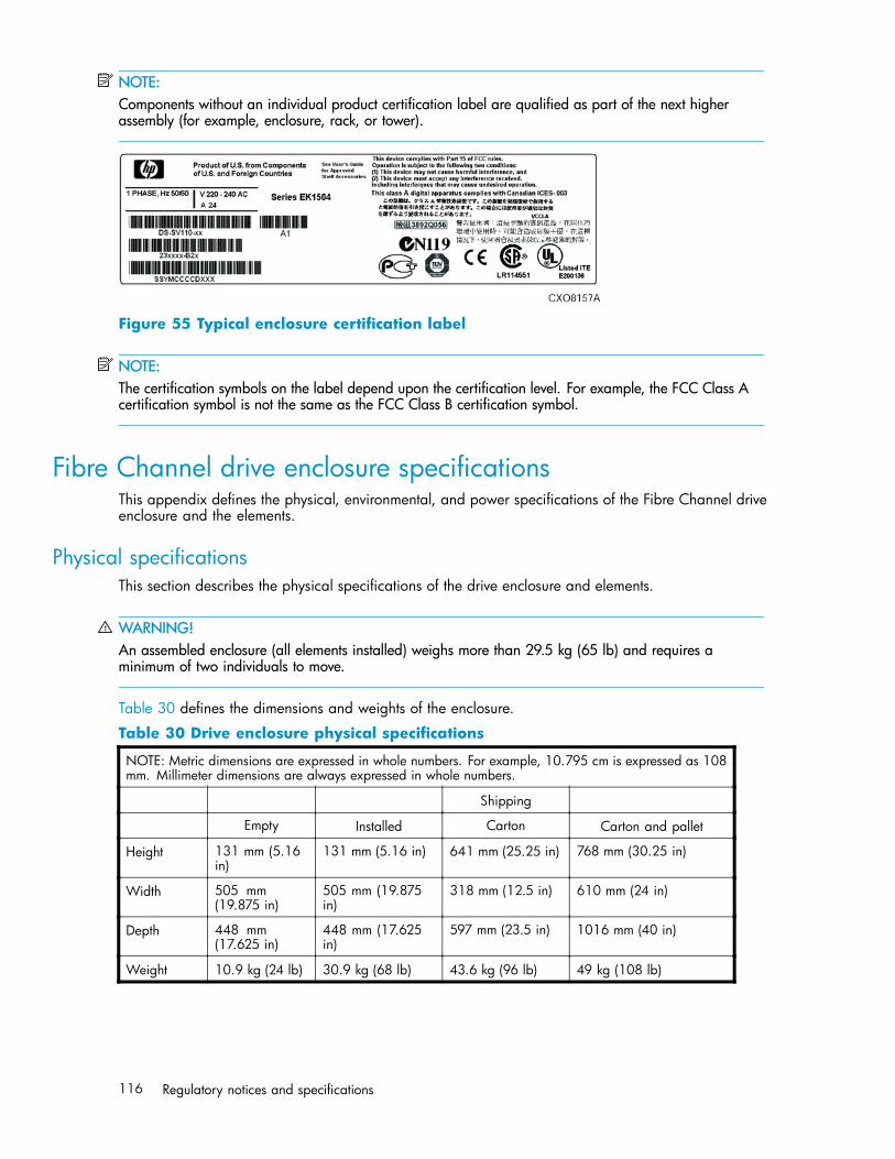
NOTE:Components without an individual product certification label are qualified as part of the next higherassembly (for example, enclosure, rack, or tower).
Figure 55 Typical enclosure certification label
NOTE:The certification symbols on the label depend upon the certification level. For example, the FCC Class Acertification symbol is not the same as the FCC Class B certification symbol.
Fibre Channel drive enclosure specificationsThis appendix defines the physical, environmental, and power specifications of the Fibre Channel driveenclosure and the elements.
Physical specificationsThis section describes the physical specifications of the drive enclosure and elements.
WARNING!An assembled enclosure (all elements installed) weighs more than 29.5 kg (65 lb) and requires aminimum of two individuals to move.
Table 30 defines the dimensions and weights of the enclosure.
Table 30 Drive enclosure physical specifications
NOTE: Metric dimensions are expressed in whole numbers. For example, 10.795 cm is expressed as 108mm. Millimeter dimensions are always expressed in whole numbers.
Shipping
Empty Installed Carton Carton and pallet
Height 131 mm (5.16in)
131 mm (5.16 in) 641 mm (25.25 in) 768 mm (30.25 in)
Width 505 mm(19.875 in)
505 mm (19.875in)
318 mm (12.5 in) 610 mm (24 in)
Depth 448 mm(17.625 in)
448 mm (17.625in)
597 mm (23.5 in) 1016 mm (40 in)
Weight 10.9 kg (24 lb) 30.9 kg (68 lb) 43.6 kg (96 lb) 49 kg (108 lb)
116 Regulatory notices and specifications
Environmental specificationsTo ensure optimum product operation, you must maintain the operational environmental specificationslisted in Table 31. The ambient temperature (the enclosure air intake or room temperature) is especiallycritical.
Table 31 Environmental operating specifications
Ambient temperature: +10 °C to +35 °C (+50 °F to +95 °F) with an average rate of change of 1 °C/hourmaximum and a step change of 3 °C or less. Maintaining the optimum ambient temperature within thespecified range ensures that the internal operating temperatures support the drive manufacturer’s MTBFspecifications.
Relative humidity: 40% to 60% (noncondensing) with a step change of 10% or less (noncondensing)
Air quality: Not to exceed a maximum of 500,000 particles, 0.5 micron or larger, per cubic foot of air.
Heat dissipation: 1600 BTUs per hour
When shipping, or placing this product in short term storage, HP recommends maintaining theenvironmental conditions listed in Table 32.
Table 32 Environmental shipping or short-term storage specifications
Ambient temperature: –40 °C to +66 °C (–40 °F to +151 °F)
Relative humidity: 10% to 80% (noncondensing)
Altitude: 15,240 m (50,000 ft)
Power specificationsThe input voltage to the drive enclosure power supplies is a function of the country-specific input voltageto Enterprise storage system rack power distribution units (PDUs). Enterprise storage system AC input linevoltages defines the AC input power available to the drive enclosure power supplies.
4000/6000/8000 Enterprise Virtual Array user guide 117

CAUTION:The AC power distribution within a rack ensures a balanced to each PDA and reduces the possibility ofan overload condition. Changing the cabling to or from a PDM could cause an overload condition.
Table 33 Enterprise storage system AC input line voltages
Specification Minimal Nominal Maximum
60 Hz service
AC Line Voltage 57 Hz 60 Hz 63 Hz
AC Line Voltage—Japan 180 VAC 202 VAC 220 VAC
AC Line Voltage–North America 180 VAC 208 VAC 220 VAC
AC Line Voltage–Europe 208 VAC 240 VAC 254 VAC
50 Hz service
AC Line Frequency 47 Hz 50 Hz 53 Hz
AC Line Voltage–Japan 180 VAC 202 VAC 220 VAC
AC Line Voltage–North America 190 VAC 220 VAC 235 VAC
AC Line Voltage–North America 200 VAC 230 VAC 244 VAC
AC Line Voltage–Europe 208 VAC 240 VAC 254 VAC
Table 34 defines the AC input current and wattage to the drive enclosure power supplies.
Table 34 AC input current and wattage
Nominal Maximum
Input voltage Amps Watts Amps Watts
60–Hz input
100 VAC–JBOD 4.35 436 6.41 641
208 VAC–North America 2.03 419 2.94 609
50–Hz Input
120 VAC–JBOD 3.59 419 5.27 633
220 VAC–North America 1.92 418 2.78 608
230 VAC–North America 1.92 418 2.78 608
240 VAC–Europe 1.76 416 2.55 607
118 Regulatory notices and specifications
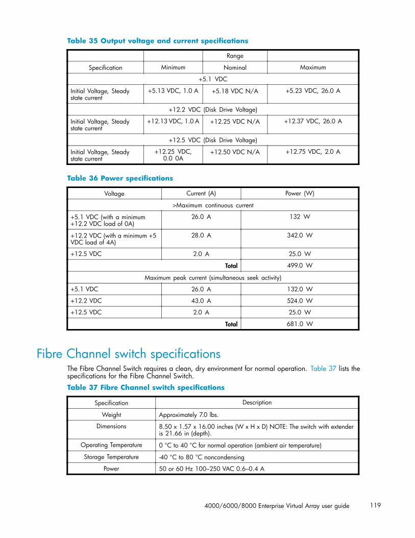
Table 35 Output voltage and current specifications
Range
Specification Minimum Nominal Maximum
+5.1 VDC
Initial Voltage, Steadystate current
+5.13 VDC, 1.0 A +5.18 VDC N/A +5.23 VDC, 26.0 A
+12.2 VDC (Disk Drive Voltage)
Initial Voltage, Steadystate current
+12.13 VDC, 1.0 A +12.25 VDC N/A +12.37 VDC, 26.0 A
+12.5 VDC (Disk Drive Voltage)
Initial Voltage, Steadystate current
+12.25 VDC,0.0 0A
+12.50 VDC N/A +12.75 VDC, 2.0 A
Table 36 Power specifications
Voltage Current (A) Power (W)
>Maximum continuous current
+5.1 VDC (with a minimum+12.2 VDC load of 0A)
26.0 A 132 W
+12.2 VDC (with a minimum +5VDC load of 4A)
28.0 A 342.0 W
+12.5 VDC 2.0 A 25.0 W
Total 499.0 W
Maximum peak current (simultaneous seek activity)
+5.1 VDC 26.0 A 132.0 W
+12.2 VDC 43.0 A 524.0 W
+12.5 VDC 2.0 A 25.0 W
Total 681.0 W
Fibre Channel switch specificationsThe Fibre Channel Switch requires a clean, dry environment for normal operation. Table 37 lists thespecifications for the Fibre Channel Switch.
Table 37 Fibre Channel switch specifications
Specification Description
Weight Approximately 7.0 lbs.
Dimensions 8.50 x 1.57 x 16.00 inches (W x H x D) NOTE: The switch with extenderis 21.66 in (depth).
Operating Temperature 0 °C to 40 °C for normal operation (ambient air temperature)
Storage Temperature -40 °C to 80 °C noncondensing
Power 50 or 60 Hz 100–250 VAC 0.6–0.4 A
4000/6000/8000 Enterprise Virtual Array user guide 119
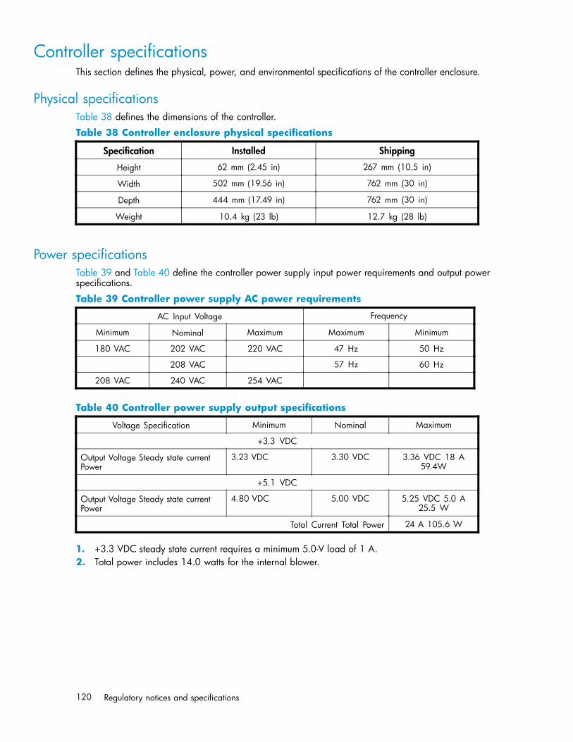
Controller specificationsThis section defines the physical, power, and environmental specifications of the controller enclosure.
Physical specificationsTable 38 defines the dimensions of the controller.
Table 38 Controller enclosure physical specifications
Specification Installed Shipping
Height 62 mm (2.45 in) 267 mm (10.5 in)
Width 502 mm (19.56 in) 762 mm (30 in)
Depth 444 mm (17.49 in) 762 mm (30 in)
Weight 10.4 kg (23 lb) 12.7 kg (28 lb)
Power specificationsTable 39 and Table 40 define the controller power supply input power requirements and output powerspecifications.
Table 39 Controller power supply AC power requirements
AC Input Voltage Frequency
Minimum Nominal Maximum Maximum Minimum
180 VAC 202 VAC 220 VAC 47 Hz 50 Hz
208 VAC 57 Hz 60 Hz
208 VAC 240 VAC 254 VAC
Table 40 Controller power supply output specifications
Voltage Specification Minimum Nominal Maximum
+3.3 VDC
Output Voltage Steady state currentPower
3.23 VDC 3.30 VDC 3.36 VDC 18 A59.4W
+5.1 VDC
Output Voltage Steady state currentPower
4.80 VDC 5.00 VDC 5.25 VDC 5.0 A25.5 W
Total Current Total Power 24 A 105.6 W
1. +3.3 VDC steady state current requires a minimum 5.0-V load of 1 A.2. Total power includes 14.0 watts for the internal blower.
120 Regulatory notices and specifications
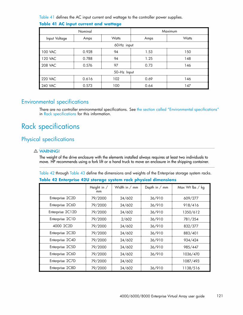
Table 41 defines the AC input current and wattage to the controller power supplies.
Table 41 AC input current and wattage
Nominal Maximum
Input Voltage Amps Watts Amps Watts
60-Hz input
100 VAC 0.928 94 1.53 150
120 VAC 0.788 94 1.25 148
208 VAC 0.576 97 0.73 146
50–Hz Input
220 VAC 0.616 102 0.69 146
240 VAC 0.573 100 0.64 147
Environmental specificationsThere are no controller environmental specifications. See the section called “Environmental specifications”in Rack specifications for this information.
Rack specifications
Physical specifications
WARNING!The weight of the drive enclosure with the elements installed always requires at least two individuals tomove. HP recommends using a fork lift or a hand truck to move an enclosure in the shipping container.
Table 42 through Table 43 define the dimensions and weights of the Enterprise storage system racks.
Table 42 Enterprise 42U storage system rack physical dimensions
Height in /mm
Width in / mm Depth in / mm Max Wt lbs / kg
Enterprise 2C2D 79/2000 24/602 36/910 609/277
Enterprise 2C6D 79/2000 24/602 36/910 918/416
Enterprise 2C12D 79/2000 24/602 36/910 1350/612
Enterprise 2C1D 79/2000 2/602 36/910 781/354
4000 2C2D 79/2000 24/602 36/910 832/377
Enterprise 2C3D 79/2000 24/602 36/910 883/401
Enterprise 2C4D 79/2000 24/602 36/910 934/424
Enterprise 2C5D 79/2000 24/602 36/910 985/447
Enterprise 2C6D 79/2000 24/602 36/910 1036/470
Enterprise 2C7D 79/2000 24/602 1087/493
Enterprise 2C8D 79/2000 24/602 36/910 1138/516
4000/6000/8000 Enterprise Virtual Array user guide 121
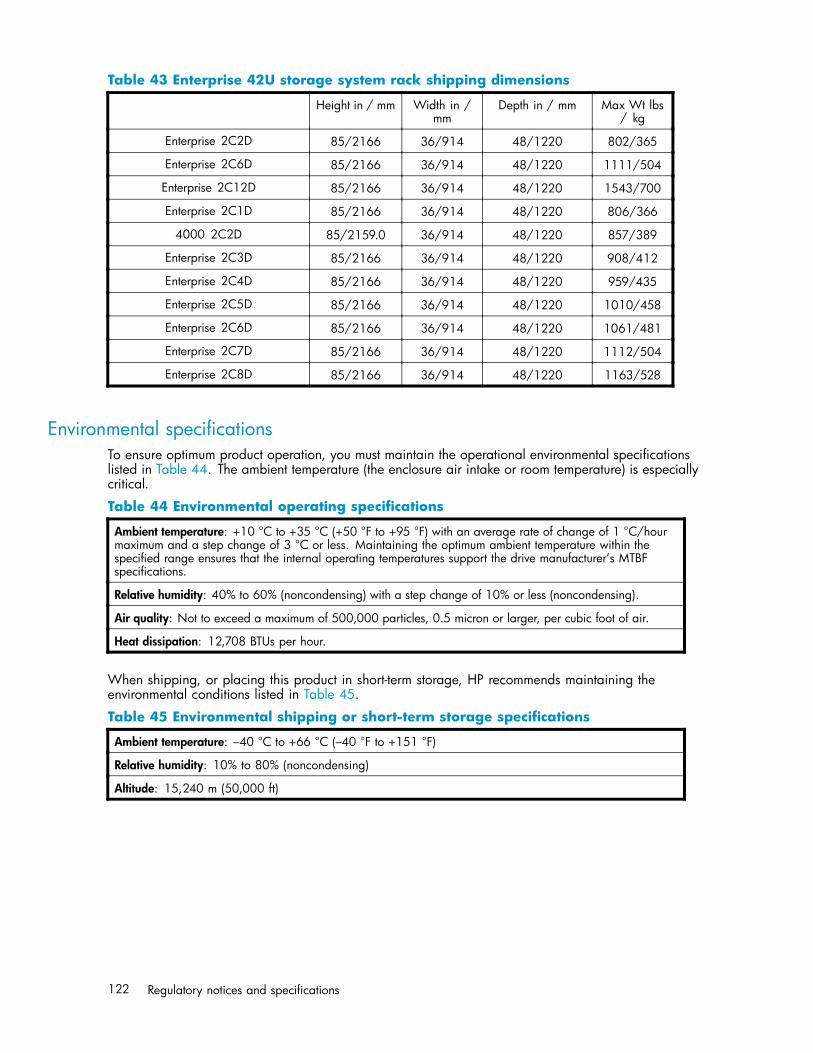
Table 43 Enterprise 42U storage system rack shipping dimensions
Height in / mm Width in /mm
Depth in / mm Max Wt lbs/ kg
Enterprise 2C2D 85/2166 36/914 48/1220 802/365
Enterprise 2C6D 85/2166 36/914 48/1220 1111/504
Enterprise 2C12D 85/2166 36/914 48/1220 1543/700
Enterprise 2C1D 85/2166 36/914 48/1220 806/366
4000 2C2D 85/2159.0 36/914 48/1220 857/389
Enterprise 2C3D 85/2166 36/914 48/1220 908/412
Enterprise 2C4D 85/2166 36/914 48/1220 959/435
Enterprise 2C5D 85/2166 36/914 48/1220 1010/458
Enterprise 2C6D 85/2166 36/914 48/1220 1061/481
Enterprise 2C7D 85/2166 36/914 48/1220 1112/504
Enterprise 2C8D 85/2166 36/914 48/1220 1163/528
Environmental specificationsTo ensure optimum product operation, you must maintain the operational environmental specificationslisted in Table 44. The ambient temperature (the enclosure air intake or room temperature) is especiallycritical.
Table 44 Environmental operating specifications
Ambient temperature: +10 °C to +35 °C (+50 °F to +95 °F) with an average rate of change of 1 °C/hourmaximum and a step change of 3 °C or less. Maintaining the optimum ambient temperature within thespecified range ensures that the internal operating temperatures support the drive manufacturer’s MTBFspecifications.
Relative humidity: 40% to 60% (noncondensing) with a step change of 10% or less (noncondensing).
Air quality: Not to exceed a maximum of 500,000 particles, 0.5 micron or larger, per cubic foot of air.
Heat dissipation: 12,708 BTUs per hour.
When shipping, or placing this product in short-term storage, HP recommends maintaining theenvironmental conditions listed in Table 45.
Table 45 Environmental shipping or short-term storage specifications
Ambient temperature: –40 °C to +66 °C (–40 °F to +151 °F)
Relative humidity: 10% to 80% (noncondensing)
Altitude: 15,240 m (50,000 ft)
122 Regulatory notices and specifications

Power specificationsTable 46 defines the AC power specifications for the enterprise storage system PDUs, PDMs, driveenclosure power supplies, and controller enclosure power supplies.
Table 46 Enterprise storage system AC power specifications
Nominal input voltage Specifications
60-Hz service
202 VAC Voltage Range PowerReceptacle
Japan 180—220 VAC, 57—63 Hz, 32 A, Single Phase 3-wire, 2-pole,IEC 309
208 VAC Voltage Range PowerReceptacle
North America 180—220 VAC, 57—63 Hz, 30 A, Single Phase 3-wire,2-pole, NEMA L6-30
240 VAC Voltage Range PowerReceptacle
Europe208—254 VAC, 57—63 Hz, 32 A, Single Phase 3-wire, 2-pole,IEC 309
50–Hz service
202 VAC Voltage Range PowerReceptacle
Japan180—220 VAC, 47—63 Hz, 32 A, Single Phase 3-wire, 2-pole,IEC 309
220 VAC Voltage Range PowerReceptacle
North America190—235 VAC, 47—63 Hz, 30 A, Single Phase 3-wire,2-pole, NEMA L6-30
230 VAC Voltage Range PowerReceptacle
North America200—244 VAC, 47—63 Hz, 30 A, Single Phase 3-wire,2-pole, NEMA L6-30
240 VAC Voltage Range PowerReceptacle
Europe208—254 VAC, 57—63 Hz, 32 A, Single Phase 3-wire, 2-pole,IEC 309
The power consumption of an enterprise storage system is 3,724 W.
4000/6000/8000 Enterprise Virtual Array user guide 123

124 Regulatory notices and specifications

B EMU-generated condition reports
This section provides a description of the EMU generated condition reports that contain the followinginformation:
• Element type (et), a hexadecimal number in the range 01 through FF.• Element number (en), a decimal number in the range 00 through 99 that defines a specific
problem.• Error code (ec), a decimal number in the range 00 through 99.• The recommended corrective action.
NOTE:The conventions used to differentiate between the elements of the condition report are:• Element type—period after each character• Element number—period after the second character• Error code—no periods
The EMU can send error messages to the controller for transmission to HP Command View EVA. Themessages displayed are specific to HP Command View EVA and are not within the scope of thispublication.
The I/O modules have the built-in intelligence to:
• Observe fibre channel events• Bypass drive ports based on events• Perform drive port testing and monitoring to prevent poor-performing drives from participating
in the loop• Communicate fibre channel events to the controllers
This appendix explains the condition report format, correcting problems, and how to identify elementtypes. The error codes are arranged in element type sequence (that is, 0.1., 0.2., 0.3., etc.).
Condition report formatWhen the EMU alphanumeric display is Er, three additional displays identify the possible cause of theproblem: the element type, the specific element, and the error code, which defines the possible causeof the problem.
• The first-level display identifies the type of element affected with two alphanumeric charactersseparated by periods such as 0.1., 0.2., 1.3., F.F., and so forth. A disk drive problem woulddisplay an element type number of 0.1.
• The second-level display identifies the element affected with a two-digit, decimal number followedby a period. For example, when a bay 6 drive error occurs, the element number display is 06.; adisplay of 14. indicates a bay 14 problem.
• The third-level display identifies a specific problem, the error code with a two-digit, decimalnumber. For example, should the problem be either the installation of an incorrectly configureddrive or one that cannot operate at the loop link rate, the display is 01.
4000/6000/8000 Enterprise Virtual Array user guide 125

Correcting errorsCorrecting an error may require you to perform a specific set of actions. In some cases, the only availablecorrective action is to replace the element.
Table 47 lists the element type codes assigned to the drive enclosure elements.
Table 47 Assigned element type codes
Code Element
0.1. Disk Drives
0.2. Power Supplies
0.3. Blowers
0.4. Temperature Sensors
0.6 Audible Alarm 1
0.7. EMU
0.C. Controller OCP LCD1
0.F. Transceivers
1.0. Language1
1.1. Communication Port1
1.2. Voltage Sensors
1. Current Sensors
8.0 Drive Enclosure1
8.2. Drive Enclosure Backplane
8.7. I/O Modules
1Does not generate a condition report. However, for any error, you should record the error code. Then, implement therecommended corrective action.
Drive conditionsThe format of a disk drive condition report is 0.1.en.ec, where:
• 0.1. is the disk drive element type number• en. is the two-character disk drive element• ec is the error code
A direct correlation exists between the disk drive element number and the bay number. However, nodirect correlation exists between the disk drive bay number and the device Fibre Channel drive enclosurephysical address. The Fibre Channel drive enclosure physical address is assigned by negotiationduring system initialization.
The following sections define the disk drive error codes.
0.1.en.01 CRITICAL condition—Drive configuration or drive link rateAs each drive spins up and comes on-line, the EMU determines if the drive is Fibre Channel compatibleand can operate at the link rate (1 Gbps or 2 Gbps) established by the I/O module. If either of theseconditions are not met, the EMU issues the condition report 0.1.en.01.
The corrective actions for these conditions are:
• When the drive is not Fibre Channel-compatible you must install a Fibre Channel compatibledrive or a drive blank.
126 EMU-generated condition reports

• When the drive is Fibre Channel-compatible, the EMU compares the drive link rate with the I/Omodule link rate, the loop link rate.
If the EMU cannot determine the drive link rate, the EMU activates the drive bypass function for oneminute. During this time the EMU continually checks the drive to determine the link rate.
• If the EMU determines the drive cannot operate at the Fibre Channel link rate set by the I/Omodule, the drive bypass function ends and the drive is placed on the loop. This does notgenerate a condition report.
• The EMU issues the condition report 0.1.en.01 when the drive link rate is incompatible withFibre Channel link rate.
• When the EMU cannot determine the drive link rate during the one-minute drive bypass time, theEMU places the drive on the loop. This process allows the drive to negotiate for an address.• If negotiation indicates the link rates are compatible, the EMU rechecks the drive link rate to
verify compatibility.• If negotiation indicates the link rates are incompatible, an error condition exists and drive
loop data transfers stop.
This condition report remains active until the problem is corrected. The problem affects disk drive en.Therefore, correction to prevent the possible failure of other elements is not required.
Complete the following procedure to correct this problem:
1. Record all six characters of the condition report.
2. Replace the defective drive with:
• A Fibre Channel-compatible drive.• A Fibre Channel drive capable of operating at a link rate supported by I/O modules and
transceivers.3. Observe the EMU to ensure the error is corrected.
4. If unable to correct the problem, contact your authorized service representative.
0.1.en.02 INFORMATION condition—Drive missingThe drive is improperly installed or missing. Either option could affect the enclosure air flow and cause anovertemperature condition for another element.
• This error remains active for one minute, or until the problem is corrected, whichever occurs first.• Immediate correction is not required. However, correction cannot be delayed indefinitely.
Complete the following procedure to correct this problem.
1. Record all six characters of the condition report.
2. Remove and install the drive to ensure that it is properly installed.
3. Observe the EMU to ensure the error is corrected.
4. If removing and installing the drive did not correct the problem, install a replacement drive or adrive blank.
5. Observe the EMU to ensure the error is corrected.
6. If unable to correct the problem, contact your authorized service representative.
0.1.en.03 INFORMATION condition—Drive software lock activeSome enclosures have a software-activated lock that prevents physically removing a drive while this featureis active. This feature can be activated even when an enclosure does not have a physical lock. Removinga drive when this feature is active generates a condition report. This error remains active for 15 seconds.
No action is required to correct this condition.
4000/6000/8000 Enterprise Virtual Array user guide 127

0.1.en.04 CRITICAL condition—Loop a drive link rate incorrectThe drive is capable of operating at the loop link rate but is running at a different rate. For example, thedrive is operating at 1 Gbps, and the loop is operating at 2 Gbps. Only when the drive is operating atthe Fibre Channel link rate established by the I/O module can this drive transfer data.
This error remains active until the problem is corrected.
Complete the following procedure to correct this problem:
1. Record all six characters of the condition report.
2. Remove and replace the drive in the enclosure.
3. Observe the drive status indicators to ensure the drive is operational.
4. Observe the EMU to ensure the error is corrected.
5. If removing and replacing the drive did not correct the problem, replace the drive.
6. Observe the drive status indicators to ensure the drive is operational.
7. Observe the EMU to ensure the error is corrected.
8. If unable to correct the problem, contact your authorized service representative.
0.1.en.05 CRITICAL condition—Loop b drive link rate incorrectThe drive is capable of operating at the loop link rate but is running at a different rate. For example, thedrive is operating at 1 Gbps, and the loop is operating at 2 Gbps. Only when the drive is operating atthe Fibre Channel link rate established by the I/O module can this drive transfer data.
This error remains active until the problem is corrected.
Complete the following procedure to correct this problem:
1. Record all six characters of the condition report.
2. Remove and replace the drive in the enclosure.
3. Observe the drive status indicators to ensure the drive is operational.
4. Observe the EMU to ensure the error is corrected.
5. If removing and replacing the drive did not correct the problem, replace the drive.
6. Observe the drive status indicators to ensure the drive is operational.
7. Observe the EMU to ensure the error is corrected.
8. If unable to correct the problem, contact your authorized service representative.
Power supply conditionsThe format of a power supply condition report is 0.2.en.ec, where:
• 0.2. is the power supply element type number• en. is the two-character power supply element number• ec is the error code
Figure 56 shows the location of power supply 1 and power supply 2.
128 EMU-generated condition reports

CXO7952A1 2
Figure 56 Power supply element numbering
The following sections define the power supply condition reports.
0.2.en.01 NONCRITICAL Condition—Power supply AC input missingThe loss of the AC input to a power supply makes the remaining power supply a single point of failure.
This condition report remains active until AC power is applied to the power supply.
Complete the following procedure to correct this problem:
1. Record all six characters of the condition report.
2. Ensure that there is AC power to the rack PDU, and from the PDU to the PDMs and that the PDU andPDM circuit breakers are not reset.
If there is no AC power to the PDU, contact building facilities management.
Verify that the power supply AC power cord is properly connected.
3. If AC is present, and the rack power distribution circuitry is functioning properly, the power supplyindicator should be on.
4. Observe the EMU to ensure the error is corrected.
5. Contact your authorized service representative.
0.2.en.02 UNRECOVERABLE condition—Power supply missingThis condition report indicates a power supply is not installed or installed incorrectly. Both of theseconditions affect air flow within the enclosure and can cause an overtemperature condition. Enclosureshutdown is imminent.
The operational power supply will automatically shut down after seven minutes, thereby disabling theenclosure. This condition report remains active until either the problem is corrected, or the operationalpower supply shuts down, whichever occurs first.
To correct this problem, record all six characters of the condition report, then contact your authorizedservice representative.
CAUTION:Removing power from an enclosure may cause the loss or corruption of data. To avoid this condition, shutdown the system using HP Command View EVA. An automatic shutdown and possible data corruptionmay result if the power supply is removed before a replacement is available.
0.2.en.03 CRITICAL condition—Power supply load unbalancedThis condition report indicates that a component within a power supply may have failed. This can makethe remaining power supply a single point of failure.
This condition report remains active until corrected.
Complete the following procedure to correct this problem:
4000/6000/8000 Enterprise Virtual Array user guide 129

1. Record all six characters of the condition report.
2. Ensure that the blower on the power supply is functioning properly. If not, correct the blowercondition and wait one minute.
3. Contact your authorized service representative.
Blower conditionsThe format of a blower condition report is 0.3.en.ec, where:
• 0.3. is the blower element type number• en. is the two-character blower element number• ec is the error code
As shown in Figure 57, blower 1 is in location 1 and blower 2 is in location 2.
CXO7953A1 2
Figure 57 Blower element numbering
CAUTION:A single blower operating at high speed can provide sufficient air flow to cool an enclosure and theelements for up to 100 hours. However, operating an enclosure at temperatures approaching anoverheating threshold can damage elements and may reduce the MTBF of a specific element. Immediatereplacement of the defective blower is required.
The following sections define the power supply condition reports.
0.3.en.01 NONCRITICAL condition—Blower speedA blower is operating at a speed outside of the EMU specified range, possibly because of a bearingproblem. This can affect enclosure cooling and cause an element to fail. This condition report remainsactive until the problem is corrected.
This error does not normally require immediate correction. However, an error of this type could contributeto an element overheating.
HP recommends replacing the blower as soon as possible.
To correct this problem, record all six characters of the condition report, then contact your HP authorizedservice representative.
0.3.en.02 CRITICAL condition—Blower speedA blower is operating at a speed that is significantly outside the EMU specified range, possibly becauseof a bearing problem. This can cause the loss of cooling and cause an element to fail. The error remainsactive until the problem is corrected.
HP recommends replacing the blower as soon as possible.
To correct this problem, record all six characters of the condition report, then contact your authorizedservice representative.
130 EMU-generated condition reports

0.3.en.03 UNRECOVERABLE condition—Blower failureA blower has stopped. The operational blower now operates at high speed and is a single point offailure. This condition report remains active until the problem is corrected.
To correct this problem, record all six characters of the condition report, then contact your authorizedservice representative.
0.3.en.04 UNRECOVERABLE condition—Blower internalA power supply reported an internal blower error that could affect enclosure cooling and cause anelement to fail. HP recommends correcting the problem before the blower fails. This condition reportremains active until the problem is corrected.
To correct this problem, record all six characters of the condition report, then contact your HP authorizedservice representative.
0.3.en.05 NONCRITICAL condition—Blower missingA blower has been removed or is improperly installed. Even though the blower flaps close to maintainthe proper air flow, the reduced cooling capability can cause overheating, causing an element to fail.This condition report remains active until the problem is corrected.
To correct this problem, record all six characters of the condition report, then contact your HP authorizedservice representative.
0.3.en.06 UNRECOVERABLE condition—No blowers installed
NOTE:IMPORTANTWhen this condition exists there will be two error messages.The first message will be 0.3.en.05 and will identify the first blower.The second message will be 0.3.en.06 and will identify the second blower.
The EMU cannot detect any installed blowers. Shutdown is imminent! The EMU will shut down theenclosure in seven minutes unless you correct the problem. This condition report remains active until youcorrect the problem or the EMU shuts down the power supplies, whichever occurs first.
Complete the following procedure to correct this problem.
1. Record all six characters of the condition report.
2. Use the controller shutdown procedure to shut down the controllers.
3. Contact your authorized service representative.
CAUTION:An automatic shutdown and possible data corruption may result if the blower is removed beforea replacement is available.
Temperature conditionsThe format of a temperature condition report is 0.4.en.ec, where:
• 0.4. is temperature sensor element type• en. is the two-character temperature sensor element• ec is the error code
4000/6000/8000 Enterprise Virtual Array user guide 131
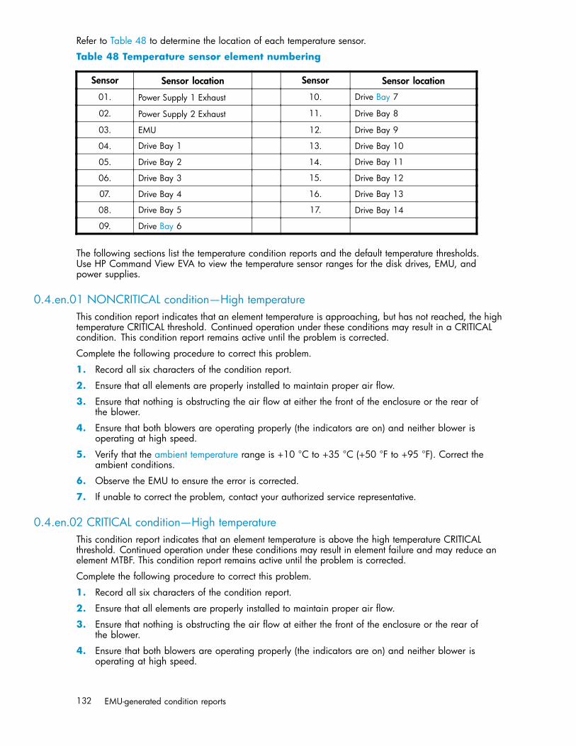
Refer to Table 48 to determine the location of each temperature sensor.
Table 48 Temperature sensor element numbering
Sensor Sensor location Sensor Sensor location
01. Power Supply 1 Exhaust 10. Drive Bay 7
02. Power Supply 2 Exhaust 11. Drive Bay 8
03. EMU 12. Drive Bay 9
04. Drive Bay 1 13. Drive Bay 10
05. Drive Bay 2 14. Drive Bay 11
06. Drive Bay 3 15. Drive Bay 12
07. Drive Bay 4 16. Drive Bay 13
08. Drive Bay 5 17. Drive Bay 14
09. Drive Bay 6
The following sections list the temperature condition reports and the default temperature thresholds.Use HP Command View EVA to view the temperature sensor ranges for the disk drives, EMU, andpower supplies.
0.4.en.01 NONCRITICAL condition—High temperatureThis condition report indicates that an element temperature is approaching, but has not reached, the hightemperature CRITICAL threshold. Continued operation under these conditions may result in a CRITICALcondition. This condition report remains active until the problem is corrected.
Complete the following procedure to correct this problem.
1. Record all six characters of the condition report.
2. Ensure that all elements are properly installed to maintain proper air flow.
3. Ensure that nothing is obstructing the air flow at either the front of the enclosure or the rear ofthe blower.
4. Ensure that both blowers are operating properly (the indicators are on) and neither blower isoperating at high speed.
5. Verify that the ambient temperature range is +10 °C to +35 °C (+50 °F to +95 °F). Correct theambient conditions.
6. Observe the EMU to ensure the error is corrected.
7. If unable to correct the problem, contact your authorized service representative.
0.4.en.02 CRITICAL condition—High temperatureThis condition report indicates that an element temperature is above the high temperature CRITICALthreshold. Continued operation under these conditions may result in element failure and may reduce anelement MTBF. This condition report remains active until the problem is corrected.
Complete the following procedure to correct this problem.
1. Record all six characters of the condition report.
2. Ensure that all elements are properly installed to maintain proper air flow.
3. Ensure that nothing is obstructing the air flow at either the front of the enclosure or the rear ofthe blower.
4. Ensure that both blowers are operating properly (the indicators are on) and neither blower isoperating at high speed.
132 EMU-generated condition reports
5. Verify that the ambient temperature range is +10 °C to +35 °C (+50 °F to +95 °F). Adjust asnecessary.
6. Observe the EMU to ensure the error is corrected.
7. If unable to correct the problem, contact your authorized service representative.
0.4.en.03 NONCRITICAL condition—Low temperatureThis condition report indicates that an element temperature is approaching, but has not reached, the lowtemperature CRITICAL threshold. Continued operation under these conditions may result in a CRITICALcondition. This condition report remains active until the problem is corrected.
Complete the following procedure to correct this problem.
1. Record all six characters of the condition report.
2. Verify that the ambient temperature range is +10 °C to +35 °C (+50 °F to +95 °F). Adjust asnecessary.
3. Observe the EMU to ensure the error is corrected.
4. If the ambient temperature is correct and the problem persists, contact your Authorized ServiceRepresentative.
0.4.en.04 CRITICAL condition—Low temperatureThis condition report indicates that an element temperature has reached the low temperature CRITICALthreshold. HP recommends correcting this error to prevent affecting other elements. This conditionreport remains active until the problem is corrected.
Complete the following procedure to correct this problem.
1. Record all six characters of the condition report.
2. Verify that the ambient temperature range is +10 °C to +35 °C (+50 °F to +95 °F). Adjust asnecessary.
3. Observe the EMU to ensure the error is corrected.
4. If the ambient temperature is correct and the problem persists, contact your authorized servicerepresentative.
0.4.en.05 UNRECOVERABLE condition—High temperatureThis condition report indicates that the EMU has evaluated the temperature of the three temperaturegroups (EMU, disk drives, and power supplies), and determined that the average temperature of twoof the three groups exceeds the critical level (use HP Command View EVA to view the temperaturethresholds). Under these conditions the EMU starts a timer that will automatically shut down the enclosurein seven minutes unless you correct the problem. Enclosure shutdown is imminent!
CAUTION:An automatic shutdown and possible data corruption may result if the procedure below is not performedimmediately.
Complete the following procedure to correct this problem.
1. Ensure that all disk drives, I/O modules, and power supply elements are fully seated.
2. Ensure that all blowers are operating properly.
3. Verify that the ambient temperature range is +10 °C to +35 °C (+50 °F to +95 °F). Adjust asnecessary.
4000/6000/8000 Enterprise Virtual Array user guide 133

4. If steps 1, 2 or 3 did not reveal a problem, use HP Command View EVA to request the HSV210controller to shut down the drive enclosure. Completing this action will halt the drive enclosuredata transfers.
5. Contact your authorized service representative and request assistance.
EMU conditionsThe format of an EMU condition report is 0.7.01.ec, where:
• 0.7. is the EMU element type number• 01. is the two-character EMU element number• ec is the error code
NOTE:There is only one EMU in a drive enclosure. Therefore, the element number is always 01.
Resetting the EMUIn some cases, the only corrective action for an EMU error is to replace the EMU. Call your authorizedservice representative if this action is required. Another option is to reset the EMU using the followingprocedure.
1. Firmly grasp the EMU mounting handle and pull the EMU partially out of the enclosure.
NOTE:You do not need to remove the EMU from the enclosure or disconnect the cables. You mustavoid putting any strain on the cables or connectors.
2. Wait 30 seconds, and then push the EMU in and fully seat the element in the backplane. The EMUshould display any enclosure condition report within two minutes.
07.01.01 CRITICAL condition—EMU internal clockThere is an internal EMU clock error that will remain active until the problem is corrected.
Complete the following procedure to correct this problem.
1. Record all six characters of the condition report.
2. Reset the EMU.
3. If resetting the EMU did not correct the problem, replace the EMU.
4. Observe the EMU to ensure the error is corrected.
5. If unable to correct the problem, contact your HP authorized service representative.
07.01.02 UNRECOVERABLE condition—EMU interruptedThe Inter-IC (I2C) bus is not processing data and the EMU is unable to monitor or report the status of theelements or enclosures. IMMEDIATE corrective action is required to ensure proper enclosure operation.This condition report remains active until the problem is corrected.
Complete the following procedure NOW to correct this problem.
1. Record all six characters of the condition report.
2. Reset the EMU.
3. Observe the EMU to ensure the error is corrected.
134 EMU-generated condition reports
4. If resetting the EMU did not correct the problem, replace the EMU.
5. If unable to correct the problem, contact your HP authorized service representative.
0.7.01.03 UNRECOVERABLE Condition—Power supply shutdownThis message only appears in HP Command View EVA to report a power supply has already shutdown. This message can be the result of the controller shutdown command or an EMU or power supplyinitiated power shutdown.
This message cannot be displayed until after restoration of power. Therefore, there is no correctiveaction required.
0.7.01.04 INFORMATION condition—EMU internal dataThe EMU is unable to collect data for the SCSI-3 Engineering Services (SES) page. This condition reportremains active for 15 seconds. The condition report affects only internal EMU operations. There is nodegradation of enclosure operations.
The EMU initiates automatic recovery procedures.
If the problem is not automatically corrected after one minute, contact your HP authorized servicerepresentative.
0.7.01.05 UNRECOVERABLE condition—Backplane NVRAM
NOTE:IMPORTANTBackplane NVRAM errors usually occur during manufacture. At this time they are identified andcorrected. They rarely occur during normal operation.
When a backplane NVRAM is not programmed or cannot be read by the EMU, there is nocommunication with the disk drives. This condition report remains active until the problem is corrected.
Complete the following procedure to correct this problem.
1. Record all six characters of the condition report.
2. Reset the EMU.
3. Observe the EMU to ensure the error is corrected.
4. If resetting the EMU did not correct the problem, contact your HP authorized service representative.
0.7.01.10 NONCRITICAL condition—NVRAM invalid read dataThe data read from the EMU NVRAM is invalid. This error initiates an automatic recovery process. Thiscondition report remains active until the problem is corrected.
If the automatic recovery process does not correct the problem, complete the following procedure.
1. Record all six characters of the condition report.
2. Reset the EMU.
3. Observe the EMU to ensure the error is corrected.
4. If resetting the enclosure did not correct the problem, contact your HP authorized servicerepresentative.
0.7.01.11 NONCRITICAL condition—EMU NVRAM write failureThe EMU cannot write data to the NVRAM. This condition report remains active until the problem iscorrected.
4000/6000/8000 Enterprise Virtual Array user guide 135

Complete the following procedure to correct this problem:
1. Record all six characters of the condition report.
2. Reset the EMU.
3. Observe the EMU to ensure the error is corrected.
4. If resetting the enclosure did not correct the problem, contact your HP authorized servicerepresentative.
0.7.01.12 NONCRITICAL condition—EMU cannot read NVRAM dataThe EMU is unable to read data from the NVRAM. This condition report remains active until the problemis corrected.
Complete the following procedure to correct this problem:
1. Record all six characters of the condition report.
2. Reset the EMU.
3. Observe the EMU to ensure the error is corrected.
4. If resetting the enclosure did not correct the problem, contact your HP authorized servicerepresentative.
0.7.01.13 UNRECOVERABLE condition—EMU load failureThe EMU Field Programmable Gate Array (FPGA) that controls the ESI bus failed to load informationrequired for EMU operation. This condition report remains active until the problem is corrected.
Complete the following procedure to correct this problem:
1. Record all six characters of the condition report.
2. Reset the EMU.
3. Observe the EMU to ensure the error is corrected.
4. If resetting the enclosure did not correct the problem, contact your HP authorized servicerepresentative.
0.7.01.14 NONCRITICAL condition—EMU enclosure addressEither the enclosure address is incorrect or the enclosure has no address. Possible causes include adefective enclosure address bus cable, an incorrectly connected cable, or a defective enclosure addressbus enclosure ID expansion cable. This condition report remains active until the problem is corrected.
Complete the following procedure to correct this problem:
1. Record all six characters of the condition report.
2. Remove and reconnect the cable between the address bus enclosure ID expansion cable and theEMU.
NOTE:The EMU display may not display a change in condition for up to 30 seconds.
3. Observe the EMU to ensure the error is corrected.
4. If the problem is not corrected, remove and reinstall the lower and upper terminators, and all theenclosure ID expansion cable-to-enclosure ID expansion cables.
5. Observe the EMU to ensure the error is corrected.
6. Reset the EMU, then observe the EMU to ensure the error is corrected.
7. If resetting the EMU did not correct the problem, contact your HP authorized service representative.
136 EMU-generated condition reports

0.7.01.15 UNRECOVERABLE condition—EMU hardware failureThe EMU has detected an internal hardware problem. This condition report remains active until theproblem is corrected.
Complete the following procedure to correct this problem:
1. Record all six characters of the condition report.
2. Reset the EMU.
3. Observe the EMU to ensure the error does not recur within the first minute.
4. If the error does recur, contact your HP authorized service representative. The EMU is inoperativeand must be replaced as soon as possible.
0.7.01.16 INFORMATION condition—EMU internal ESI data corruptedThe EMU ESI data is corrupted. This condition does not affect any other element and no action is required.
0.7.01.17 UNRECOVERABLE condition—Power shutdown failureThe power supply did not respond to a controller, EMU, or power supply shut down command. Shuttingdown the supply is required to prevent overheating.
Complete the following procedure to correct the problem:
1. Record all six characters of the condition report.
2. Move the power cord bail lock 1, Figure 58, to the left.
3. Disconnect the AC power cord 2 from the supply.
CXO7490A
2 31
4
Figure 58 Disconnecting AC power
0.7.01.18 UNRECOVERABLE condition—EMU hardware failureThe EMU has detected an internal hardware problem. This condition report remains active until theproblem is corrected.
Complete the following procedure to correct this problem:
1. Record all six characters of the condition report.
2. Reset the EMU.
3. Observe the EMU to ensure the error does not recur within the first minute.
4000/6000/8000 Enterprise Virtual Array user guide 137
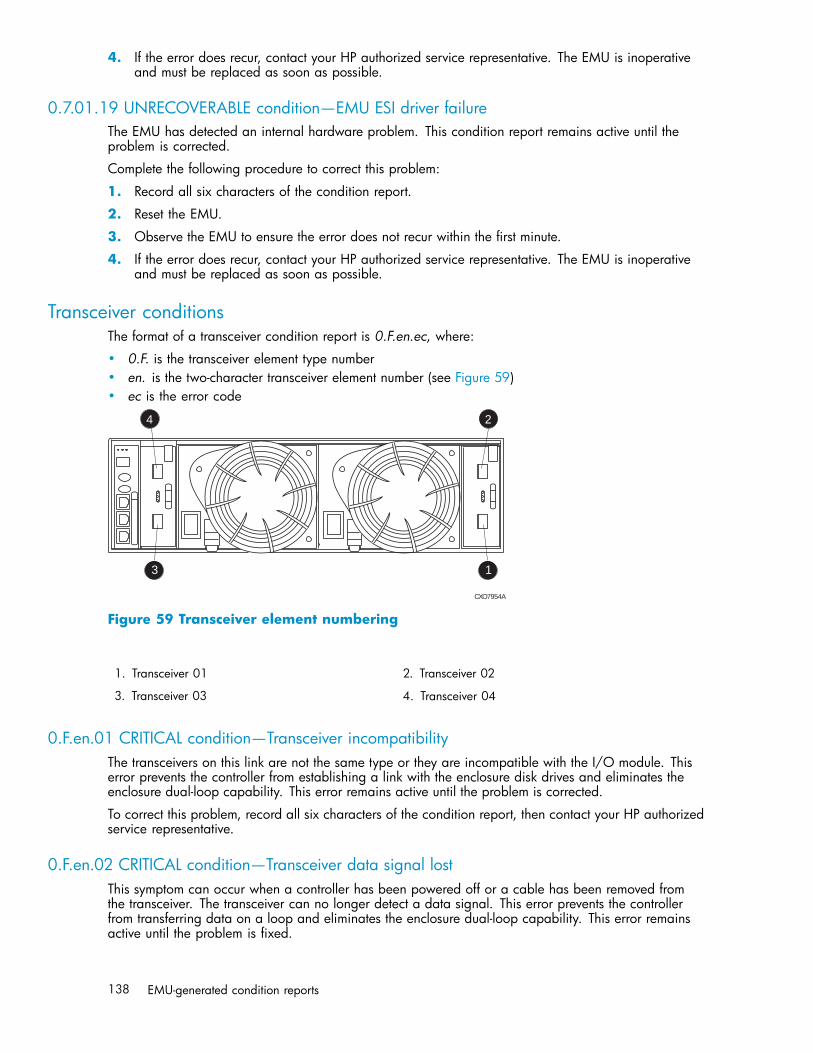
4. If the error does recur, contact your HP authorized service representative. The EMU is inoperativeand must be replaced as soon as possible.
0.7.01.19 UNRECOVERABLE condition—EMU ESI driver failureThe EMU has detected an internal hardware problem. This condition report remains active until theproblem is corrected.
Complete the following procedure to correct this problem:
1. Record all six characters of the condition report.
2. Reset the EMU.
3. Observe the EMU to ensure the error does not recur within the first minute.
4. If the error does recur, contact your HP authorized service representative. The EMU is inoperativeand must be replaced as soon as possible.
Transceiver conditionsThe format of a transceiver condition report is 0.F.en.ec, where:
• 0.F. is the transceiver element type number• en. is the two-character transceiver element number (see Figure 59)• ec is the error code
CXO7954A
3 1
4 2
Figure 59 Transceiver element numbering
1. Transceiver 01 2. Transceiver 02
3. Transceiver 03 4. Transceiver 04
0.F.en.01 CRITICAL condition—Transceiver incompatibilityThe transceivers on this link are not the same type or they are incompatible with the I/O module. Thiserror prevents the controller from establishing a link with the enclosure disk drives and eliminates theenclosure dual-loop capability. This error remains active until the problem is corrected.
To correct this problem, record all six characters of the condition report, then contact your HP authorizedservice representative.
0.F.en.02 CRITICAL condition—Transceiver data signal lostThis symptom can occur when a controller has been powered off or a cable has been removed fromthe transceiver. The transceiver can no longer detect a data signal. This error prevents the controllerfrom transferring data on a loop and eliminates the enclosure dual-loop capability. This error remainsactive until the problem is fixed.
138 EMU-generated condition reports
To correct this problem, record all six characters of the condition report, then contact your HP authorizedservice representative.
0.F.en.03 CRITICAL condition—Transceiver fibre channel drive enclosure bus faultThe system has detected a Fibre Channel drive enclosure bus fault involving a transceiver. This errorprevents the controller from transferring data on a loop and eliminates the enclosure dual-loop capability.
Complete the following procedure to correct this problem:
1. Record all six characters of the condition report.
2. Check all the transceivers and cables to ensure they are properly connected.
3. Check all the transceivers on the loop to ensure they are compatible with the I/O module.
4. If the problem persists, contact your HP authorized service representative.
0.F.en.04 CRITICAL condition—Transceiver removedThe EMU detects that a transceiver has been removed. This error remains active until the problem is fixed.
The error can be cleared by doing one of the following:
1. Install a new transceiver,
or
Reconfigure the system by switching from a loop topology to one with Vixel switches, then thetransceiver is not necessary.
2. Clear the error by resetting the EMU or by removing and then re-installing the I/O module.
0.F.en.05 CRITICAL condition—Invalid fibre channel characterThis symptom can occur under the following conditions:
• The incoming data stream is corrupted.• A cable is not completely connected.• The signal is degraded.
This error prevents the controller from transferring data on a loop and eliminates the enclosure dual-loopcapability. This error remains active until the problem is fixed.
To correct this problem, record all six characters of the condition report, then contact your HP authorizedservice representative.
Voltage sensor and current sensor conditionsThe format of these sensor condition reports is 1.2.en.ec for a voltage sensor, and 1.3.en.ec for acurrent sensor, where:
• 1.2. is the voltage sensor element type• 1.3. is the current sensor element type number• en. is the sensor element number• ec is the error code
4000/6000/8000 Enterprise Virtual Array user guide 139
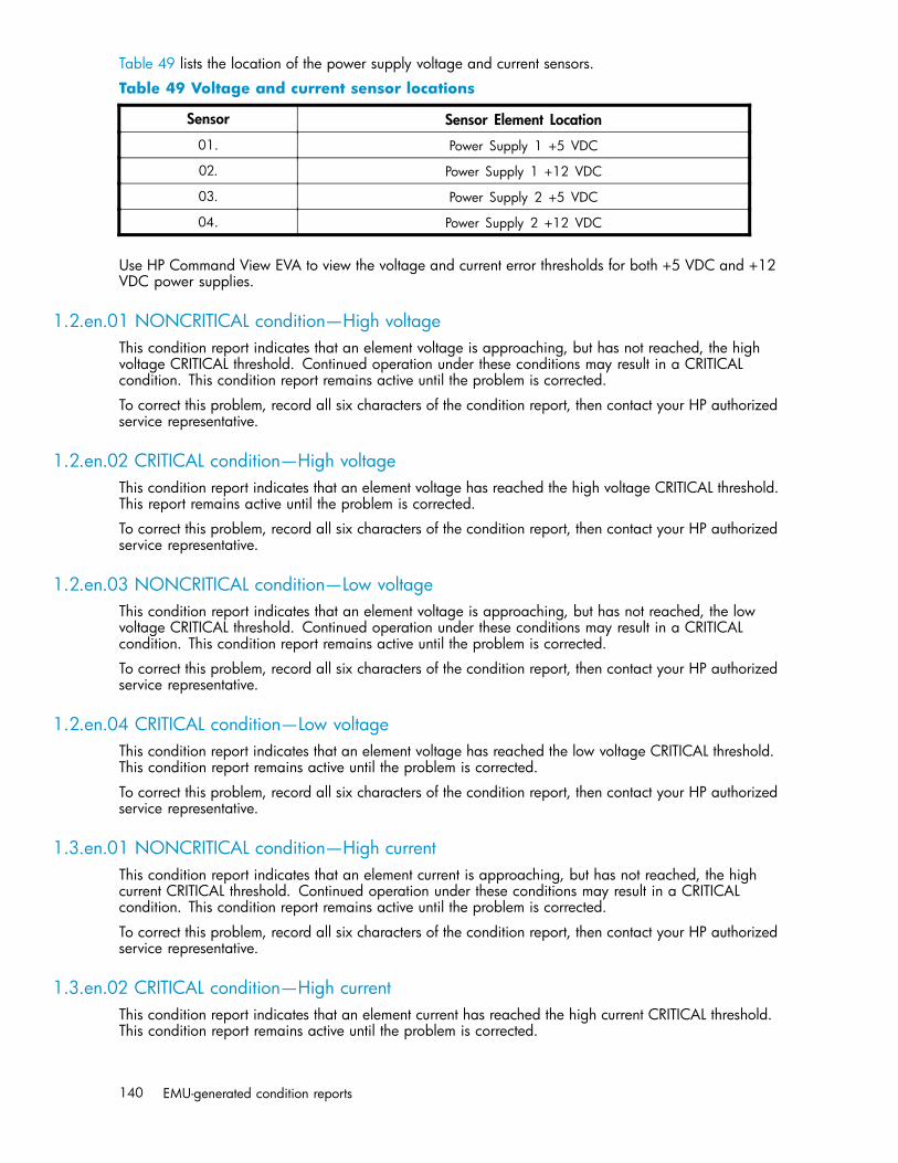
Table 49 lists the location of the power supply voltage and current sensors.
Table 49 Voltage and current sensor locations
Sensor Sensor Element Location
01. Power Supply 1 +5 VDC
02. Power Supply 1 +12 VDC
03. Power Supply 2 +5 VDC
04. Power Supply 2 +12 VDC
Use HP Command View EVA to view the voltage and current error thresholds for both +5 VDC and +12VDC power supplies.
1.2.en.01 NONCRITICAL condition—High voltageThis condition report indicates that an element voltage is approaching, but has not reached, the highvoltage CRITICAL threshold. Continued operation under these conditions may result in a CRITICALcondition. This condition report remains active until the problem is corrected.
To correct this problem, record all six characters of the condition report, then contact your HP authorizedservice representative.
1.2.en.02 CRITICAL condition—High voltageThis condition report indicates that an element voltage has reached the high voltage CRITICAL threshold.This report remains active until the problem is corrected.
To correct this problem, record all six characters of the condition report, then contact your HP authorizedservice representative.
1.2.en.03 NONCRITICAL condition—Low voltageThis condition report indicates that an element voltage is approaching, but has not reached, the lowvoltage CRITICAL threshold. Continued operation under these conditions may result in a CRITICALcondition. This condition report remains active until the problem is corrected.
To correct this problem, record all six characters of the condition report, then contact your HP authorizedservice representative.
1.2.en.04 CRITICAL condition—Low voltageThis condition report indicates that an element voltage has reached the low voltage CRITICAL threshold.This condition report remains active until the problem is corrected.
To correct this problem, record all six characters of the condition report, then contact your HP authorizedservice representative.
1.3.en.01 NONCRITICAL condition—High currentThis condition report indicates that an element current is approaching, but has not reached, the highcurrent CRITICAL threshold. Continued operation under these conditions may result in a CRITICALcondition. This condition report remains active until the problem is corrected.
To correct this problem, record all six characters of the condition report, then contact your HP authorizedservice representative.
1.3.en.02 CRITICAL condition—High currentThis condition report indicates that an element current has reached the high current CRITICAL threshold.This condition report remains active until the problem is corrected.
140 EMU-generated condition reports

To correct this problem, record all six characters of the condition report, then contact your HP authorizedservice representative.
Backplane conditions
IMPORTANT:Backplane NVRAM errors usually occur during manufacture. At this time they are identified andcorrected. They rarely occur during normal operation.
The format of a backplane condition report is 8.2.01.ec, where:
• 8.2. is the backplane element type number• 01. is the two-character backplane element number• ec is the error code
The only corrective action available for this error is to replace the drive enclosure.
8.2.01.10 NONCRITICAL condition—Backplane NVRAM readAn invalid NVRAM read occurred and an automatic recovery process has begun. This condition report isactive for 15 seconds.
If the automatic recovery process does not correct the problem, record all six characters of the conditionreport, then contact your HP authorized service representative.
8.2.01.11 NONCRITICAL condition—Backplane NVRAM write failureThe system is unable to write data to the NVRAM. This problem prevents communication betweenelements in the enclosure. This condition report is active for 15 seconds.
To correct this problem, record all six characters of the condition report, then contact your HP authorizedservice representative.
8.2.01.12 NONCRITICAL condition—Backplane NVRAM read failureThe system is unable to read data from the NVRAM. This problem prevents communication betweenelements in the enclosure. This condition report is active for 15 seconds.
To correct this problem, record all six characters of the condition report, then contact your HP authorizedservice representative.
8.2.01.13 NONCRITICAL condition—Backplane WWN is blankThe system is unable to read valid data from the NVRAM. This report is active until corrected. Thiscondition can result in incorrect device location data being displayed.
To correct this problem, record all six characters of the condition report, then contact your HP authorizedservice representative.
I/O Module conditionsThe format of an I/O module condition report is 8.7.en.ec, where:
• 8.7. is the I/O module element type number• en. is the two-character I/O module element number (see Figure 60)• ec is the error code
4000/6000/8000 Enterprise Virtual Array user guide 141
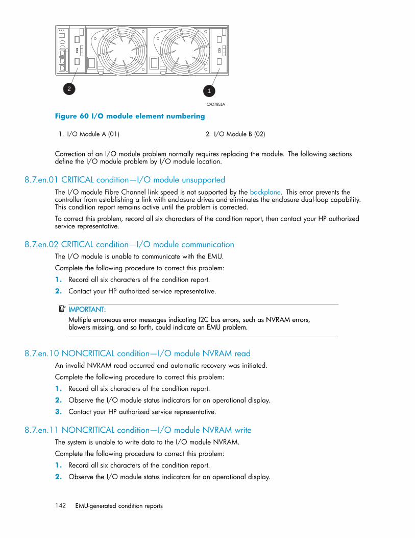
CXO7951A
12
Figure 60 I/O module element numbering
1. I/O Module A (01) 2. I/O Module B (02)
Correction of an I/O module problem normally requires replacing the module. The following sectionsdefine the I/O module problem by I/O module location.
8.7.en.01 CRITICAL condition—I/O module unsupportedThe I/O module Fibre Channel link speed is not supported by the backplane. This error prevents thecontroller from establishing a link with enclosure drives and eliminates the enclosure dual-loop capability.This condition report remains active until the problem is corrected.
To correct this problem, record all six characters of the condition report, then contact your HP authorizedservice representative.
8.7.en.02 CRITICAL condition—I/O module communicationThe I/O module is unable to communicate with the EMU.
Complete the following procedure to correct this problem:
1. Record all six characters of the condition report.
2. Contact your HP authorized service representative.
IMPORTANT:Multiple erroneous error messages indicating I2C bus errors, such as NVRAM errors,blowers missing, and so forth, could indicate an EMU problem.
8.7.en.10 NONCRITICAL condition—I/O module NVRAM readAn invalid NVRAM read occurred and automatic recovery was initiated.
Complete the following procedure to correct this problem:
1. Record all six characters of the condition report.
2. Observe the I/O module status indicators for an operational display.
3. Contact your HP authorized service representative.
8.7.en.11 NONCRITICAL condition—I/O module NVRAM writeThe system is unable to write data to the I/O module NVRAM.
Complete the following procedure to correct this problem:
1. Record all six characters of the condition report.
2. Observe the I/O module status indicators for an operational display.
142 EMU-generated condition reports

3. Contact your HP authorized service representative.
8.7.en.12 NONCRITICAL condition—I/O Module NVRAM read failureThe system is unable to read data from the I/O module NVRAM.
Complete the following procedure to correct this problem:
1. Record all six characters of the condition report.
2. Contact your HP authorized service representative.
8.7.en.13 NONCRITICAL condition—I/O module removedThe system detects that an I/O module has been removed.
To correct the problem, install an I/O module.
Host conditionsThe EMU has the capability of displaying host controller defined condition reports on the EMUalphanumeric display.
The format of a host condition report is F.F.en.ec, where:
• F.F. is the host element type number• en. is the two-character host element number• ec is the error code
The host controller can display host controller defined error codes on the EMU alphanumeric display
4000/6000/8000 Enterprise Virtual Array user guide 143

144 EMU-generated condition reports

C Controller fault management
This appendix describes how the controller displays events and termination event information. Terminationevent information is displayed on the LCD. HP Command View EVA enables you to view controller events.This appendix also discusses how to identify and correct problems.
Once you create a storage system, an error condition message has priority over other controller displays.
HP Command View EVA provides detailed descriptions of the storage system error conditions, or faults.The Fault Management displays provide similar information on the LCD, but not in as much detail.Whenever possible, refer to HP Command View EVA for fault information.
Using HP Command View EVAHP Command View EVA provides detailed information about each event affecting system operation ineither a Termination Event display or an Event display. These displays are similar, but not identical.
GUI termination event displayA problem that generates the Termination Event display prevents the system from performing a specificfunction or process. You can use the information in this display (see GUI Termination Event Display)to diagnose and correct the problem.
NOTE:The major differences between the Termination Event display and the Event display are:• The Termination Event display includes a Code Flag field; it does not include the EIP Type field.• The Event display includes an EIP type field; it does not include a Code Flag field.• The Event display includes a Corrective Action Code field.
Date Time SWCID Evt No Code Flag Descrip-tion
Figure 61 GUI termination event display
The fields in the Termination Event display include:
• Date—The date the event occurred.• Time—The time the event occurred.• SWCID—Software Identification Code. A hexadecimal number in the range 0–FF that identifies
the controller software component reporting the event.• Evt No—Event Number. A hexadecimal number in the range 0–FF that is the software component
identification number.• Code Flag—An internal code that includes a combination of other flags.• Description—The condition that generated the event. This field may contain information about an
individual field’s content and validity.
GUI event displayA problem that generates the Event display reduces the system capabilities. You can use the informationin this display (see Figure 62) to diagnose and correct problems.
4000/6000/8000 Enterprise Virtual Array user guide 145
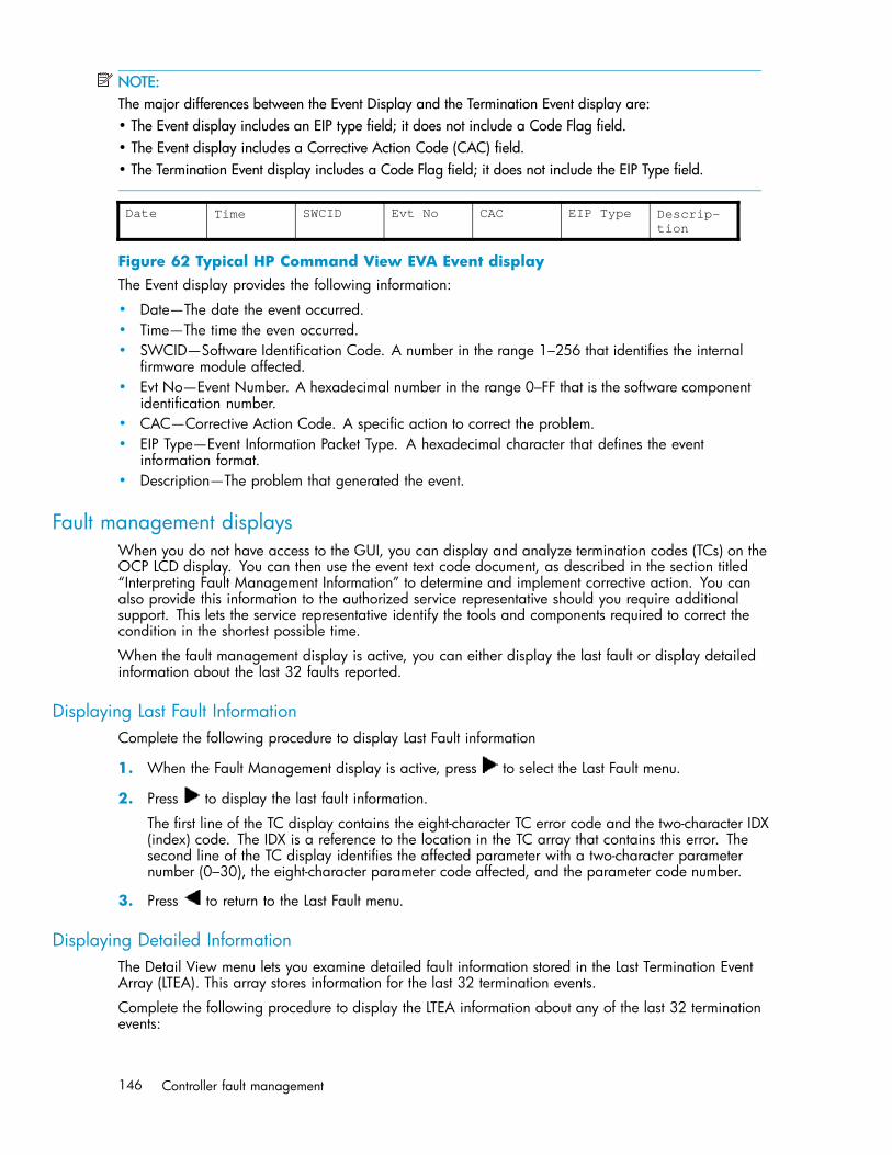
NOTE:The major differences between the Event Display and the Termination Event display are:• The Event display includes an EIP type field; it does not include a Code Flag field.• The Event display includes a Corrective Action Code (CAC) field.• The Termination Event display includes a Code Flag field; it does not include the EIP Type field.
Date Time SWCID Evt No CAC EIP Type Descrip-tion
Figure 62 Typical HP Command View EVA Event displayThe Event display provides the following information:
• Date—The date the event occurred.• Time—The time the even occurred.• SWCID—Software Identification Code. A number in the range 1–256 that identifies the internal
firmware module affected.• Evt No—Event Number. A hexadecimal number in the range 0–FF that is the software component
identification number.• CAC—Corrective Action Code. A specific action to correct the problem.• EIP Type—Event Information Packet Type. A hexadecimal character that defines the event
information format.• Description—The problem that generated the event.
Fault management displaysWhen you do not have access to the GUI, you can display and analyze termination codes (TCs) on theOCP LCD display. You can then use the event text code document, as described in the section titled“Interpreting Fault Management Information” to determine and implement corrective action. You canalso provide this information to the authorized service representative should you require additionalsupport. This lets the service representative identify the tools and components required to correct thecondition in the shortest possible time.
When the fault management display is active, you can either display the last fault or display detailedinformation about the last 32 faults reported.
Displaying Last Fault InformationComplete the following procedure to display Last Fault information
1. When the Fault Management display is active, press to select the Last Fault menu.
2. Press to display the last fault information.
The first line of the TC display contains the eight-character TC error code and the two-character IDX(index) code. The IDX is a reference to the location in the TC array that contains this error. Thesecond line of the TC display identifies the affected parameter with a two-character parameternumber (0–30), the eight-character parameter code affected, and the parameter code number.
3. Press to return to the Last Fault menu.
Displaying Detailed InformationThe Detail View menu lets you examine detailed fault information stored in the Last Termination EventArray (LTEA). This array stores information for the last 32 termination events.
Complete the following procedure to display the LTEA information about any of the last 32 terminationevents:
146 Controller fault management
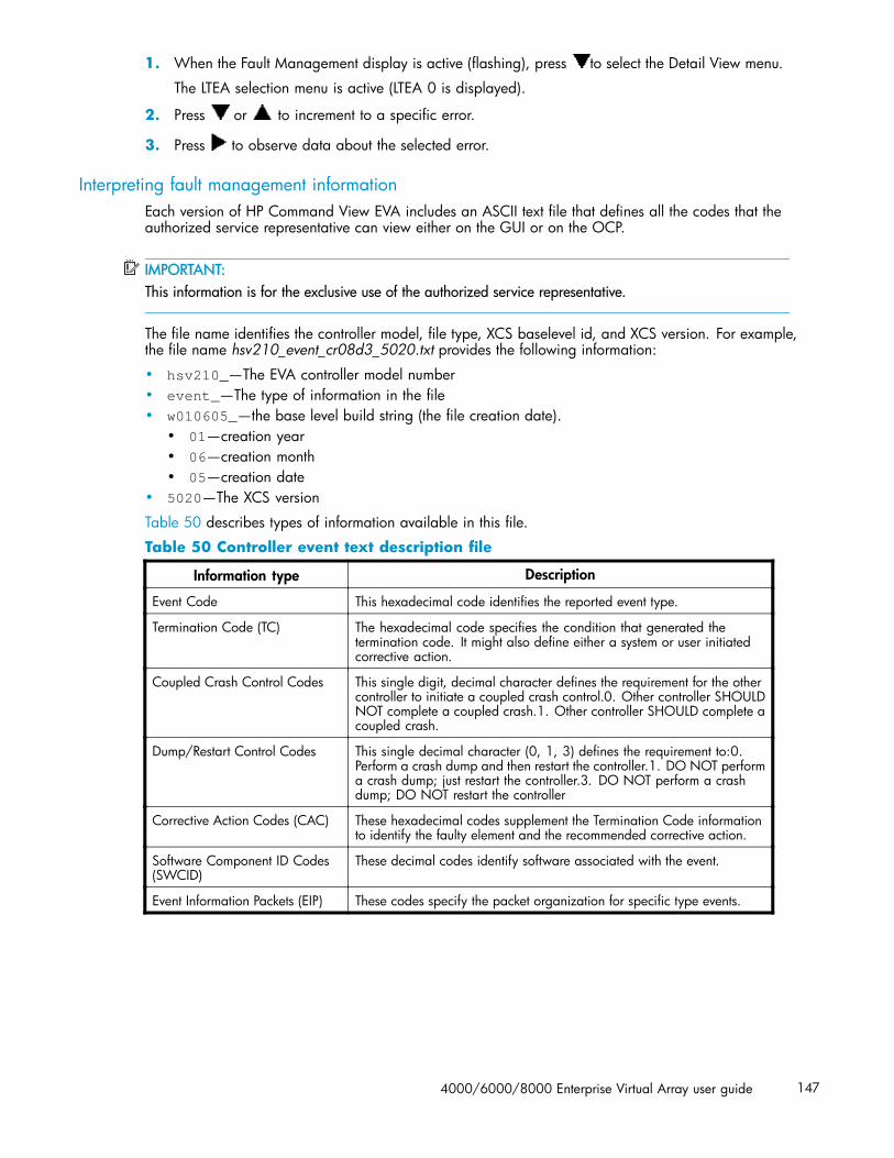
1. When the Fault Management display is active (flashing), press to select the Detail View menu.
The LTEA selection menu is active (LTEA 0 is displayed).
2. Press or to increment to a specific error.
3. Press to observe data about the selected error.
Interpreting fault management informationEach version of HP Command View EVA includes an ASCII text file that defines all the codes that theauthorized service representative can view either on the GUI or on the OCP.
IMPORTANT:This information is for the exclusive use of the authorized service representative.
The file name identifies the controller model, file type, XCS baselevel id, and XCS version. For example,the file name hsv210_event_cr08d3_5020.txt provides the following information:
• hsv210_—The EVA controller model number• event_—The type of information in the file• w010605_—the base level build string (the file creation date).
• 01—creation year• 06—creation month• 05—creation date
• 5020—The XCS version
Table 50 describes types of information available in this file.
Table 50 Controller event text description file
Information type Description
Event Code This hexadecimal code identifies the reported event type.
Termination Code (TC) The hexadecimal code specifies the condition that generated thetermination code. It might also define either a system or user initiatedcorrective action.
Coupled Crash Control Codes This single digit, decimal character defines the requirement for the othercontroller to initiate a coupled crash control.0. Other controller SHOULDNOT complete a coupled crash.1. Other controller SHOULD complete acoupled crash.
Dump/Restart Control Codes This single decimal character (0, 1, 3) defines the requirement to:0.Perform a crash dump and then restart the controller.1. DO NOT performa crash dump; just restart the controller.3. DO NOT perform a crashdump; DO NOT restart the controller
Corrective Action Codes (CAC) These hexadecimal codes supplement the Termination Code informationto identify the faulty element and the recommended corrective action.
Software Component ID Codes(SWCID)
These decimal codes identify software associated with the event.
Event Information Packets (EIP) These codes specify the packet organization for specific type events.
4000/6000/8000 Enterprise Virtual Array user guide 147

148 Controller fault management

Glossary
This glossary defines terms used in this guide or related to this product and is not a comprehensiveglossary of computer terms.
μm A symbol for micrometer; one millionth of a meter. For example, 50 μm isequivalent to 0.000050 m.
3U A unit of measurement representing three “U” spaces. “U” spacing is used todesignate panel or enclosure heights. Three “U” spaces is equivalent to 5.25inches (133 mm).See also rack-mounting unit.
active memberof a virtual diskfamily
An active member of a virtual disk family is a simulated disk drive createdby the controllers as storage for one or more hosts. An active member of avirtual disk family is accessible by one or more hosts for normal storage. Anactive virtual disk member and its snapshot, if one exists, constitute a virtual diskfamily. An active member of a virtual disk family is the only necessary memberof a virtual disk family.See also virtual disk,virtual disk copy,virtual disk family,and snapshot.
adapter See controller.
AL_PA Arbitrated Loop Physical Address. A 1-byte value the arbitrated loop topologyuses to identify the loop ports. This value becomes the last byte of the addressidentifier for each public port on the loop.
allocation policy Storage system rules that govern how virtual disks are created. AllocateCompletely and Allocate on Demand are the two rules used in creating virtualdisks.• Allocate Completely—The space a virtual disk requires on the physical disks
is reserved, even if the virtual disk is not currently using the space.• Allocate on Demand—The space a virtual disk requires on the physical
disks is not reserved until needed.
ambient tempera-ture
The air temperature in the area where a system is installed. Also called intaketemperature or room temperature.
ANSI American National Standards Institute. A non-governmental organization thatdevelops standards (such as SCSI I/O interface standards and Fibre Channelinterface standards) used voluntarily by many manufacturers within the UnitedStates.
arbitrated loop A Fibre Channel topology that links multiple ports (up to 126) together on asingle shared simplex media. Transmissions can only occur between a singlepair of nodes at any given time. Arbitration is the scheme that determines whichnode has control of the loop at any given moment
arbitrated loopphysical address
See AL_PA.
arbitrated looptopology
See arbitrated loop.
array All the physical disk drives in a storage system that are known to and underthe control of a controller pair.
4000/6000/8000 Enterprise Virtual Array user guide 149
array controller See controller.
asynchronous Events scheduled as the result of a signal requesting the event or that which iswithout any specified time relation.
audible alarm The Environmental Monitoring Unit (EMU) alarm that sounds when there is adrive enclosure element condition report. The audible alarm can be mutedor disabled.
backplane An electronic printed circuit board that distributes data, control, power, andother signals to element connectors.
bad block A data block that contains a physical defect.
bad block replace-ment
A replacement routine that substitutes defect-free disk blocks for those found tohave defects. This process takes place in the controller and is transparent tothe host.
bail lock Part of the power supply AC receptacle that engages the AC power cordconnector to ensure that the cord cannot be accidentally disconnected.
baud The maximum rate of signal state changes per second on a communicationcircuit. If each signal state change corresponds to a code bit, then the baudrate and the bit rate are the same. It is also possible for signal state changesto correspond to more than one code bit so the baud rate may be lower thanthe code bit rate.
bay The physical location of an element, such as a drive, I/O module, EMU orpower supply in a drive enclosure. Each bay is numbered to define its location.
bidirectional Also called Bi-Di. The movement of optical signals in opposite directions througha common fiber cable such as the data flow path typically on a parallel printerport. A parallel port can provide two-way data flow for disk drives, scanningdevices, FAX operations and even parallel modems.
block Also called a sector. The smallest collection of consecutive bytes addressableon a disk drive. In integrated storage elements, a block contains 512 bytes ofdata, error codes, flags, and the block address header.
blower A variable speed airflow device that pulls air into an enclosure or element. Itusually pulls air in from the front and exhausts the heated air out the rear.
cabinet An alternate term used for a rack.
cable assembly A fiber optic cable that has connectors installed on one or both ends. Generaluse of these cable assemblies includes the interconnection of multimode fiberoptic cable assemblies with either LC or SC type connectors.• When there is a connector on only one end of the cable, the cable assembly
is referred to as a pigtail.• When there is a connector on each end of the cable, the cable assembly
is referred to as a jumper.
CAC Corrective Action Code. An HP Command View EVA graphical user interface(GUI) display component that defines the action required to correct a problem.See also read cache,write cache, and mirrored cache.
cache High-speed memory that sets aside data as an intermediate data buffer betweena host and the storage media. The purpose of cache is to improve performance.
cache battery A rechargeable unit mounted within a controller enclosure that supplies back-uppower to the cache module in case of primary power shortage.
150 Glossary

cache battery in-dicator
1. An orange light emitting diode (indicator) that illuminates on the controlleroperator control panel (OCP) to define the status of the HSV Controllercache batteries.
2. An amber status indicator that illuminates on a cache battery. Whenilluminated, it indicates that one or more cache battery cells have failedand the battery must be replaced with a new battery.
carrier A drive-enclosure-compatible assembly containing a disk drive or other storagedevices.
client A software program that uses the services of another software program. The HPCommand View EVA client is a standard internet browser.
clone See Virtual Disk Copy.
communicationlogical unit num-ber (LUN)
See console LUN.
condition report A three-element code generated by the EMU in the form where e.t. is theelement type (a hexadecimal number), en. is the element number (a decimalnumber), and ec is the condition code (a decimal number).
console LUN A SCSI-3 virtual object that makes a controller pair accessible by the host beforeany virtual disks are created. Also called a communication LUN.
console LUN ID The ID that can be assigned when a host operating system requires a unique ID.The console LUN ID is assigned by the user, usually when the storage systemis initialized.See also console LUN.
controller A hardware/firmware device that manages communications between hostsystems and other devices. Controllers typically differ by the type of interface tothe host and provide functions beyond those the devices support.
controller enclo-sure
A unit that holds one or more controllers, power supplies, blowers, cachebatteries, transceivers, and connectors.
controller event A significant occurrence involving any storage system hardware or softwarecomponent reported by the controller to HP Command View EVA.
controller faultindicator
An amber fault indicator that illuminates on the controller OCP to indicate whenthere is an HSV Controller fault.
controller pair Two interconnected controller modules which together control the disk enclosuresin the storage system.
corrective actioncode
See CAC.
CRITICAL Condi-tion
A drive enclosure EMU condition that occurs when one or more drive enclosureelements have failed or are operating outside of their specifications. The failureof the element makes continued normal operation of at least some elements inthe enclosure impossible. Some enclosure elements may be able to continuenormal operations. Only an UNRECOVERABLE condition has precedence. Thiscondition has precedence over NONCRITICAL errors and INFORMATIONcondition.
CRU Customer Replaceable Unit. A storage system element that a user can replacewithout using special tools or techniques, or special training.
customer replace-able unit
See CRU.
4000/6000/8000 Enterprise Virtual Array user guide 151
data entry mode The state in which controller information can be displayed or controllerconfiguration data can be entered. On the Enterprise Storage System, thecontroller mode is active when the LCD on the HSV Controller OCP is Flashing.
default disk group The first disk group created at the time the system in initialized. The defaultdisk group can contain the entire set of physical disks in the array or just afew of the disks.See also disk group.
Detailed FaultView
An HSV Controller OCP display that permits a user to view detailed informationabout a controller fault.
device channel A channel used to connect storage devices to a host I/O bus adapter orintelligent controller.
device ports Controller pair device ports connected to the storage system’s physical disk drivearray through the Fibre Channel drive enclosure. Also called a device-side port.
device-side ports See device ports.
DIMM Dual Inline Memory Module. A small circuit board holding memory chips.
dirty data The write-back cached data that has not been written to storage media eventhough the host operation processing the data has completed.
disk drive A carrier-mounted storage device supporting random access to fixed size blocksof data.
disk drive blank A carrier that replaces a disk drive to control airflow within a drive enclosurewhenever there is less than a full complement of storage devices.
drive enclosure A unit that holds storage system devices such as disk drives, power supplies,blowers, I/O modules, transceivers, or EMUs.
drive enclosureevent
A significant operational occurrence involving a hardware or softwarecomponent in the drive enclosure. The drive enclosure EMU reports these eventsto the controller for processing.
disk failure pro-tection
A method by which a controller pair reserves drive capacity to take over thefunctionality of a failed or failing physical disk. For each disk group, thecontrollers reserve space in the physical disk pool equivalent to the selectednumber of physical disk drives.
disk group A physical disk drive set or pool in which a virtual disk is created. A disk groupmay contain all the physical disk drives in a controller pair array or a subsetof the array.
disk migrationstate
A physical disk drive operating state. A physical disk drive can be in a stableor migration state:• Stable—The state in which the physical disk drive has no failure nor is a
failure predicted.• Migration—The state in which the disk drive is failing, or failure is predicted
to be imminent. Data is then moved off the disk onto other disk drives inthe same disk group.
disk replacementdelay
The time that elapses between a drive failure and when the controller startssearching for spare disk space. Drive replacement seldom starts immediately incase the “failure” was a glitch or temporary condition.
drive blank See disk drive blank.
drive enclosure See drive enclosure.
dual-loop A configuration where each drive is connected to a pair of controllers throughtwo loops. These two Fibre Channel loops constitute a loop pair.
152 Glossary

dual power supplyconfiguration
See redundant power configuration.
dynamic capacityexpansion
A storage system feature that provides the ability to increase the size of anexisting virtual disk. Before using this feature, you must ensure that youroperating system supports capacity expansion of a virtual disk (or LUN).
EIA Electronic Industries Alliance. A standards organization specializing in theelectrical and functional characteristics of interface equipment.
EIP Event Information Packet. The event information packet is an HSV elementhexadecimal character display that defines how an event was detected. Alsocalled the EIP type.
electromagneticinterference
See EMI.
electrostatic dis-charge
See ESD.
element 1. In a drive enclosure, a device such as an EMU, power supply, disk, blower,or I/O module. The object can be controlled, interrogated, or describedby the enclosure services process.
2. In the Open SAN Manager, a controllable object, such as the Enterprisestorage system.
Command ViewEVA GUI
The graphical user interface (GUI) through which a user can control and monitora storage system. HP Command View EVA can be installed on more than onestorage management server in a fabric. Each installation is a managementagent. The client for the agent is a standard browser.
EMI Electromagnetic Interference. The impairment of a signal by an electromagneticdisturbance.
EMU Environmental Monitoring Unit. An element which monitors the status of anenclosure, including the power, air temperature, and blower status. The EMUdetects problems and displays and reports these conditions to a user and thecontroller. In some cases, the EMU implements corrective action.
enclosure A unit used to hold various storage system devices such as disk drives,controllers, power supplies, blowers, an EMU, I/O modules, or blowers.
enclosure addressbus
An Enterprise storage system bus that interconnects and identifies controllerenclosures and disk drive enclosures by their physical location. Enclosureswithin a reporting group can exchange environmental data. This bus usesenclosure ID expansion cables to assign enclosure numbers to each enclosure.Communications over this bus do not involve the Fibre Channel drive enclosurebus and are, therefore, classified as out-of-band communications.
enclosure number(En)
One of the vertical rack-mounting positions where the enclosure is located.The positions are numbered sequentially in decimal numbers starting from thebottom of the cabinet. Each disk enclosure has its own enclosure number. Acontroller pair shares an enclosure number. If the system has an expansion rack,the enclosures in the expansion rack are numbered from 15 to 24, startingat the bottom.
enclosure services Those services that establish the mechanical environmental, electricalenvironmental, and external indicators and controls for the proper operationand maintenance of devices with an enclosure as described in the SES SCSI-3Enclosure Services Command Set (SES), Rev 8b, American National Standardfor Information Services.
4000/6000/8000 Enterprise Virtual Array user guide 153

Enclosure ServicesInterface
See ESI.
Enclosure ServicesProcessor
See ESP.
Enterprise VirtualArray
The Enterprise Virtual Array is a product that consists of one or more storagesystems. Each storage system consists of a pair of HSV controllers and the diskdrives they manage. A storage system within the Enterprise Virtual Array can beformally referred to as an Enterprise storage system, or generically referred toas the storage system.
Enterprise VirtualArray rack
A unit that holds controller enclosures, disk drive enclosures, power distributionsupplies, and enclosure address buses that, combined, comprise an Enterprisestorage system solution. Also called the Enterprise storage system rack.See also rack.
environmentalmonitoring unit
See EMU.
error code The portion of an EMU condition report that defines a problem.
ESD Electrostatic Discharge. The emission of a potentially harmful static electricvoltage as a result of improper grounding.
ESI Enclosure Services Interface. The SCSI-3 engineering services interfaceimplementation developed for StorageWorks products. A bus that connectsthe EMU to the disk drives.
ESP Enclosure Services Processor. An EMU that implements an enclosure’s servicesprocess.
event Any significant change in the state of the Enterprise storage system hardware orsoftware component reported by the controller to HP Command View EVA.See also controller event, drive enclosure event, management agent event, andtermination event.
Event InformationPacket
See EIP.
Event Number See Evt No.
Evt No. Event Number. A sequential number assigned to each Software CodeIdentification (SWCID) event. It is a decimal number in the range 0-255.
exabyte A unit of storage capacity that is the equivalent of 260 bytes or1,152,921,504,606,846,976 bytes. One exabyte is equivalent to 1,024petabytes.
fabric A Fibre Channel fabric switch or two or more interconnected Fibre Channelswitches allowing data transmission.
fabric port A port which is capable of supporting an attached arbitrated loop. This port ona loop will have the AL_PA hexadecimal address 00 (loop ID 7E), giving thefabric the highest priority access to the loop. A loop port is the gateway to thefabric for the node ports on a loop.
failover The process that takes place when one controller assumes the workload ofa failed companion controller. Failover continues until the failed controller isoperational.
fan The variable speed airflow device that cools an enclosure or element by forcingambient air into an enclosure or element and forcing heated air out the otherside.See also blower.
154 Glossary
Fault Manage-ment Code
See FMC.
Fibre Channeldrive enclosure
Fibre Channel Arbitrated Loop. The American National Standards Institute’s(ANSI) document that specifies arbitrated loop topology operation.
FC HBA Fibre Channel Host Bus Adapter. An interchangeable term for Fibre Channeladapter.See also FCA.
FCA Fibre Channel Adapter. An adapter used to connect the host server to thefabric. Also called a Host Bus Adapter (HBA) or a Fibre Channel Host BusAdapter (FC HBA).See also FC HBA.
FCC Federal Communications Commission. The federal agency responsible forestablishing standards and approving electronic devices within the United States.
FCP Fibre Channel Protocol. The mapping of SCSI-3 operations to Fibre Channel.
fiber The optical media used to implement Fibre Channel.
fiber optics The technology where light is transmitted through glass or plastic (optical)threads (fibers) for data communication or signaling purposes.
fiber optic cable A transmission medium designed to transmit digital signals in the form of pulsesof light. Fiber optic cable is noted for its properties of electrical isolation andresistance to electrostatic contamination.
fibre The international spelling that refers to the Fibre Channel standards for opticalmedia.
Fibre Channel A data transfer architecture designed for mass storage devices and otherperipheral devices that require very high bandwidth.
Fibre Channeladapter
See FCA.
Fibre ChannelLoop Switch
An enclosure that provides twelve-port central interconnect for Fibre ChannelArbitrated Loops following the ANSI Fibre Channel drive enclosure standard.
field replaceableunit
See FRU.
flush The act of writing dirty data from cache to a storage media
FMC Fault Management Code. The HP Command View EVA display of the EnterpriseStorage System error condition information.
form factor A storage industry dimensional standard for 3.5inch (89 mm) and 5.25inch(133 mm) high storage devices. Device heights are specified as low-profile(1inch or 25.4 mm), half-height (1.6inch or 41 mm), and full-height (5.25inchor 133 mm).
FPGA Field Programmable Gate Array. A programmable device with an internal arrayof logic blocks surrounded by a ring of programmable I/O blocks connectedtogether through a programmable interconnect.
frequency The number of cycles that occur in one second expressed in Hertz (Hz). Thus, 1Hz is equivalent to one cycle per second.
FRU Field Replaceable Unit. A hardware element that can be replaced in the field.This type of replacement can require special training, tools, or techniques.Therefore, FRU procedures are usually performed only by an Authorized ServiceRepresentative.
4000/6000/8000 Enterprise Virtual Array user guide 155
Gb Gigabit. A measurement of the rate at which the transfer of bits of dataoccurs. Sometimes referred to as Gbps. Nominally, a Gb is a transfer rate of1,000,000,000 (109) bits per second.For Fibre Channel transceivers or FC loops the Gb transfer rates are:• 1 Gb is a transmission rate of 1,062,500,000 bits per second.• 2 Gb is a transmission rate of 2,125,000,000 bits per second.
GB Gigabyte. A unit of measurement defining either:• A data transfer rate.• A storage or memory capacity of 1,073,741,824 (230) bytes.See also GBps.
Gbps Gigabits per second. A measurement of the rate at which the transfer of bitsof data occurs. Nominally, a Gb is a transfer rate of 1,000,000,000 (109)bits per second.See also Gb.
GBps Gigabytes per second. A measurement of the rate at which the transfer ofbytes of data occurs. A GBps is a transfer rate of 1,000,000,000 (109) bytesper second.See also GB.
Giga (G) The notation to represent 109 or 1 billion (1,000,000,000).
gigabaud An encoded bit transmission rate of one billion (109) bits per second.
gigabit See Gb.
gigabit per second See Gbps.
graphical userinterface
See GUI.
GUI Graphical User Interface. Software that displays the status of a storage systemand allows its user to control the storage system.
HBA Host Bus Adapter.See also FCA.
host A computer that runs user applications and uses (or can potentially use) one ormore virtual disks created and presented by the controller pair.
Host Bus Adapter See FCA.
host computer See host.
host link indicator The HSV Controller display that indicates the status of the storage system FibreChannel links.
host ports A connection point to one or more hosts through a Fibre Channel fabric. Ahost is a computer that runs user applications and that uses (or can potentiallyuse) one or more of the virtual disks that are created and presented by thecontroller pair.
host-side ports See host ports.
hot-pluggable A method of element replacement whereby the complete system remainsoperational during element removal or insertion. Replacement does not interruptdata transfers to other elements.
hub A communications infrastructure device to which nodes on a multi-point busor loop are physically connected. It is used to improve the manageability ofphysical cables.
156 Glossary

I/O module Input/Output module. The enclosure element that is the Fibre Channel driveenclosure interface to the host or controller. I/O modules are bus speed specific,either 1 Gb or 2 Gb.
IDX A 2-digit decimal number portion of the HSV controller termination code displaythat defines one of 32 locations in the Termination Code array that containsinformation about a specific event.See also param and TC.
in-band communi-cation
The method of communication between the EMU and controller that utilizesthe Fibre Channel drive enclosure bus.
INFORMATIONcondition
A drive enclosure EMU condition report that may require action. This conditionis for information only and does not indicate the failure of an element. Allcondition reports have precedence over an INFORMATION condition.
initialization A process that prepares a storage system for use. Specifically, the systembinds controllers together as an operational pair and establishes preliminarydata structures on the disk array. Initialization also sets up the first disk group,called the default disk group.
input/output mod-ule
See I/O module.
intake tempera-ture
See ambient temperature
interface A set of protocols used between components such as cables, connectors, andsignal levels.
JBOD Just a Bunch of Disks. A number of disks connected to one or more controllers.
K Kilo. A scientific notation denoting a multiplier of one thousand (1,000).
KB Kilobyte. A unit of measurement defining either storage or memory capacity.1. For storage, a KB is a capacity of 1,000 (103) bytes of data.2. For memory, a KB is a capacity of 1,024 (210) bytes of data.
LAN Local area network. A group of computers and associated devices that sharea common communications line and typically share the resources of a singleprocessor or server within a small geographic area.
laser A device that amplifies light waves and concentrates them in a narrow, veryintense beam.
Last Fault View An HSV Controller display defining the last reported fault condition.
Last TerminationError Array
See LTEA.
LCD Liquid Crystal Display. The indicator on a panel that is associated with anelement. The LCD is usually located on the front of an element.
indicator Light Emitting Diode. A semiconductor diode, used in an electronic display, thatemits light when a voltage is applied to it.
License Key A WWN-encoded sequence that is obtained from the license key fulfillmentWeb site.
light emittingdiode
See indicator.
link A connection between ports on Fibre Channel devices. The link is a full duplexconnection to a fabric or a simplex connection between loop devices.
4000/6000/8000 Enterprise Virtual Array user guide 157

logon Also called login, it is a procedure whereby a user or network connection isidentified as being an authorized network user or participant.
loop See arbitrated loop.
loop ID Seven-bit values numbered contiguously from 0 to 126 decimal and representthe 127 valid AL_PA values on a loop (not all 256 hexadecimal values areallowed as AL_PA values per Fibre Channel).
loop pair A Fibre Channel attachment between a controller and physical disk drives.Physical disk drives connect to controllers through paired Fibre Channelarbitrated loops. There are two loop pairs, designated loop pair 1 and looppair 2. Each loop pair consists of two loops (called loop A and loop B) thatoperate independently during normal operation, but provide mutual backupin case one loop fails.
LTEA Last Termination Event Array. A two-digit HSV Controller number that identifies aspecific event that terminated an operation. Valid numbers range from 00 to 31.
LUN Logical Unit Number. A SCSI convention used to identify elements. The hostsees a virtual disk as a LUN. The LUN address a user assigns to a virtual disk fora particular host will be the LUN at which that host will see the virtual disk.
managementagent
The HP Command View EVA software that controls and monitors the Enterprisestorage system. The software can exist on more than one management server ina fabric. Each installation is a management agent.
managementagent event
Significant occurrence to or within the management agent software, or aninitialized storage cell controlled or monitored by the management agent.
Mb Megabit. A term defining a data transfer rate.See also Mbps.
MB Megabtye. A term defining either:• A data transfer rate.• A measure of either storage or memory capacity of 1,048,576 (220) bytes.See also MBps.
Mbps Megabits per second. A measure of bandwidth or data transfers occurring at arate of 1,000,000 (106) bits per second.
MBps Megabytes per second. A measure of bandwidth or data transfers occurring ata rate of 1,000,000 (106) bytes per second.
mean time be-tween failures
See MTBF.
Mega A notation denoting a multiplier of 1 million (1,000,000).
metadata Information that a controller pair writes on the disk array. This information isused to control and monitor the array and is not readable by the host.
micro meter See μm.
mirrored caching A process in which half of each controller’s write cache mirrors the companioncontroller’s write cache. The total memory available for cached write data isreduced by half, but the level of protection is greater.
mirroring The act of creating an exact copy or image of data.
MTBF Mean Time Between Failures. The average time from start of use to first failure ina large population of identical systems, components, or devices.
158 Glossary

multi-mode fiber A fiber optic cable with a diameter large enough (50 microns or more) to allowmultiple streams of light to travel different paths from the transmitter to thereceiver. This transmission mode enables bidirectional transmissions.
Network StorageController
See NSC.
NONCRITICALCondition
A drive enclosure EMU condition report that occurs when one or more elementsinside the enclosure have failed or are operating outside of their specifications.The failure does not affect continued normal operation of the enclosure. Alldevices in the enclosure continue to operate according to their specifications.The ability of the devices to operate correctly may be reduced if additionalfailures occur. UNRECOVERABLE and CRITICAL errors have precedence overthis condition. This condition has precedence over INFORMATION condition.Early correction can prevent the loss of data.
node port A device port that can operate on the arbitrated loop topology.
non-OFC (OpenFibre Control)
A laser transceiver whose lower-intensity output does not require special openFibre Channel mechanisms for eye protection. The Enterprise storage systemtransceivers are non-OFC compatible.
NSC Network Storage Controller. The HSV Controllers used by the Enterprise storagesystem.
NVRAM Nonvolatile Random Access Memory. Memory whose contents are not lost whena system is turned Off or if there is a power failure. This is achieved throughthe use of UPS batteries or implementation technology such as flash memory.NVRAM is commonly used to store important configuration parameters.
occupancy alarmlevel
A percentage of the total disk group capacity in blocks. When the number ofblocks in the disk group that contain user data reaches this level, an event codeis generated. The alarm level is specified by the user.
OCP Operator Control Panel. The element that displays the controller’s status usingindicators and an LCD. Information selection and data entry is controlled bythe OCP push buttons.
online/nearonline An online drive is a normal, high-perfomance drive, while a near-online driveis a lower-performance drive.
operator controlpanel
See OCP.
OpenView Stor-age ManagementServer
A centralized, appliance-based monitoring and management interface thatsupports multiple applications, operating systems, hardware platforms, storagesystems, tape libraries and SAN-related interconnect devices. It is included andresides on the SANWorks Management Server, a single aggregation pointfor data management.
param That portion of the HSV controller termination code display that defines:• The 2-character parameter identifier that is a decimal number in the 0
through 30 range.• The 8-character parameter code that is a hexadecimal number.See also IDX and TC.
password A security interlock where the purpose is to allow:• A management agent to control only certain storage systems• Only certain management agents to control a storage system
PDM Power Distribution Module. A thermal circuit breaker-equipped power strip thatdistributes power from a PDU to Enterprise Storage System elements.
4000/6000/8000 Enterprise Virtual Array user guide 159

PDU Power Distribution Unit. The rack device that distributes conditioned AC or DCpower within a rack.
petabyte A unit of storage capacity that is the equivalent of 250, 1,125,899,906,842,624bytes or 1,024 terabytes.
physical disk A disk drive mounted in a drive enclosure that communicates with a controllerpair through the device-side Fibre Channel loops. A physical disk is hardwarewith embedded software, as opposed to a virtual disk, which is constructed bythe controllers. Only the controllers can communicate directly with the physicaldisks.The physical disks, in aggregate, are called the array and constitute the storagepool from which the controllers create virtual disks.
physical disk ar-ray
See array.
port A Fibre Channel connector on a Fibre Channel device.
port_name A 64-bit unique identifier assigned to each Fibre Channel port. The port_nameis communicated during the login and port discovery processes.
port-wine colored A convention of applying the color of port wine to a CRU tab, lever, or handleto identify the unit as hot-pluggable.
power distributionmodule
See PDM.
power distributionunit
See PDU.
power supply An element that develops DC voltages for operating the storage system elementsfrom either an AC or DC source.
preferred address An AL_PA which a node port attempts to acquire during loop initialization.
preferred path A preference for which controller of the controller pair manages the virtual disk.This preference is set by the user when creating the virtual disk. A host canchange the preferred path of a virtual disk at any time. The primary purpose ofpreferring a path is load balancing.
protocol The conventions or rules for the format and timing of messages sent and received.
push button A switch that is engaged or disengaged when it is pressed.
quiesce The act of rendering bus activity inactive or dormant. For example, “quiesce theSCSI bus operations during a device warm-swap.”
rack A floorstanding structure primarily designed for, and capable of, holding andsupporting storage system equipment. All racks provide for the mounting ofpanels per Electronic Industries Alliance (EIA) Standard RS310C.
rack-mountingunit
A measurement for rack heights based upon a repeating hole pattern. It isexpressed as “U” spacing or panel heights. Repeating hole patterns are spacedevery 1.75 inches (44.45 mm) and based on EIA’s Standard RS310C. Forexample, a 3U unit is 5.25inches (133.35 mm) high, and a 4U unit is 7.0inches(177.79 mm) high.
read caching A cache method used to decrease subsystem response times to a read requestby allowing the controller to satisfy the request from the cache memory ratherthan from the disk drives. Reading data from cache memory is faster thanreading data from a disk. The read cache is specified as either On or Off foreach virtual disk. The default state is on.
160 Glossary

read aheadcaching
A cache management method used to decrease the subsystem response time toa read request by allowing the controller to satisfy the request from the cachememory rather than from the disk drives.
reconstruction The process of regenerating the contents of a failed member data. Thereconstruction process writes the data to a spare set disk and incorporates thespare set disk into the mirrorset, striped mirrorset or RAID set from which thefailed member came.
redundancy 1. Element Redundancy—The degree to which logical or physical elementsare protected by having another element that can take over in case offailure. For example, each loop of a device-side loop pair normally worksindependently but can take over for the other in case of failure.
2. Data Redundancy—The level to which user data is protected. Redundancyis directly proportional to cost in terms of storage usage; the greater thelevel of data protection, the more storage space is required.
redundant powerconfiguration
A capability of the Enterprise storage system racks and enclosures to allowcontinuous system operation by preventing single points of power failure.• For a rack, two AC power sources and two power conditioning units
distribute primary and redundant AC power to enclosure power supplies.• For a controller or drive enclosure, two power supplies ensure that the DC
power is available even when there is a failure of one supply, one ACsource, or one power conditioning unit. Implementing the redundant powerconfiguration provides protection against the loss or corruption of data.
reporting group An Enterprise Storage System controller pair and the associated disk driveenclosures. The Enterprise Storage System controller assigns a unique decimalreporting group number to each EMU on its loops. Each EMU collects diskdrive environmental information from its own sub-enclosure and broadcasts thedata over the enclosure address bus to all members of the reporting group.Information from enclosures in other reporting groups is ignored.
room temperature See ambient temperature
SCSI 1. Small Computer System Interface. An American National Standards Institute(ANSI) interface which defines the physical and electrical parameters ofa parallel I/O bus used to connect computers and a maximum of 16 buselements.
2. The communication protocol used between a controller pair and the hosts.Specifically, the protocol is Fibre Channel drive enclosure or SCSI on FibreChannel. SCSI is the higher command-level protocol and Fibre Channelis the low-level transmission protocol. The controllers have full support forSCSI-2; additionally, they support some elements of SCSI-3.
SCSI-3 The ANSI standard that defines the operation and function of Fibre Channelsystems.
SCSI-3 EnclosureServices
See SES.
selective presenta-tion
The process whereby a controller presents a virtual disk only to the hostcomputer which is authorized access.
serial transmission A method of transmission in which each bit of information is sent sequentially ona single channel rather than simultaneously as in parallel transmission.
SES SCSI-3 Enclosures Services. Those services that establish the mechanicalenvironment, electrical environment, and external indicators and controls for theproper operation and maintenance of devices within an enclosure.
4000/6000/8000 Enterprise Virtual Array user guide 161

small computersystem interface
See SCSI.
Snapclone A virtual disk that can be manipulated while the data is being copied. Only anActive member of a virtual disk family can be snapcloned.The Snapclone, like a snapshot, reflects the contents of the source virtual disk ata particular point in time. Unlike the snapshot, the Snapclone is an actual cloneof the source virtual disk and immediately becomes an independent Activemember of its own virtual disk family.
snapshot A temporary virtual disk (Vdisk) that reflects the contents of another virtual diskat a particular point in time. A snapshot operation is only done on an activevirtual disk. Up to seven snapshots of an active virtual disk can exist at anypoint. The active disk and its snapshot constitute a virtual family.See also active virtual disk, virtual disk copy, and virtual disk family.
SSN Storage System Name. An HP Command View EVA-assigned, unique20-character name that identifies a specific storage system.
storage carrier See carrier.
storage pool The aggregated blocks of available storage in the total physical disk array.
storage system The controllers, storage devices, enclosures, cables, and power supplies andtheir software.
Storage SystemName
See SSN.
switch An electro-mechanical device that initiates an action or completes a circuit.
TB Terabyte. A term defining either:• A data transfer rate.• A measure of either storage or memory capacity of 1,099,5111,627,776
(240) bytes.See also TBps.
TBps Terabytes per second. A data transfer rate of 1,000,000,000,000 (1012)bytes per second.
TC Termination Code. An Enterprise Storage System controller 8-characterhexadecimal display that defines a problem causing controller operations to halt.See also IDX and param.
Termination Code See TC.
termination event Occurrences that cause the storage system to cease operation.
terminator Interconnected elements that form the ends of the transmission lines in theenclosure address bus.
topology An interconnection scheme that allows multiple Fibre Channel ports tocommunicate. Point-to-point, arbitrated loop, and switched fabric are all FibreChannel topologies.
transceiver The device that converts electrical signals to optical signals at the point where thefiber cables connect to the FC elements such as hubs, controllers, or adapters.
uninitialized sys-tem
A state in which the storage system is not ready for use.See also initialization.
UNRECOVERABLECondition
A drive enclosure EMU condition report that occurs when one or more elementsinside the enclosure have failed and have disabled the enclosure. The enclosure
162 Glossary

may be incapable of recovering or bypassing the failure and will require repairsto correct the condition.This is the highest level condition and has precedence over all other errors andrequires immediate corrective action.
unwritten cacheddata
Also called unflushed data.See also dirty data.
UPS Uninterruptible Power Supply. A battery-operated power supply guaranteed toprovide power to an electrical device in the event of an unexpected interruptionto the primary power supply. Uninterruptible power supplies are usually ratedby the amount of voltage supplied and the length of time the voltage is supplied.
Vdisk Virtual Disk. A simulated disk drive created by the controllers as storagefor one or more hosts. The virtual disk characteristics, chosen by the storageadministrator, provide a specific combination of capacity, availability,performance, and accessibility. A controller pair simulates the characteristicsof the virtual disk by deploying the disk group from which the virtual disk wascreated.The host computer sees the virtual disk as “real,” with the characteristics of anidentical physical disk.See also active virtual disk, virtual disk copy, virtual disk family, and virtualdisk snapshot.
virtual disk See Vdisk.
virtual disk copy A clone or exact replica of another virtual disk at a particular point in time.Only an active virtual disk can be copied. A copy immediately becomes theactive disk of its own virtual disk family.See also active virtual disk, virtual disk family, and virtual disk snapshot
virtual disk family A virtual disk and its snapshot, if a snapshot exists, constitute a family. Theoriginal virtual disk is called the active disk. When you first create a virtual diskfamily, the only member is the active disk.See also active virtual disk, virtual disk copy, and virtual disk snapshot.
virtual disk snap-shot
See snapshot.
Vraid0 A virtualization technique that provides no data protection. Data host is brokendown into chunks and distributed on the disks comprising the disk group fromwhich the virtual disk was created. Reading and writing to a Vraid0 virtual diskis very fast and makes the fullest use of the available storage, but there is nodata protection (redundancy) unless there is parity.
Vraid1 A virtualization technique that provides the highest level of data protection.All data blocks are mirrored or written twice on separate physical disks. Forread requests, the block can be read from either disk, which can increaseperformance. Mirroring takes the most storage space because twice the storagecapacity must be allocated for a given amount of data.
Vraid5 A virtualization technique that uses parity striping to provide moderate dataprotection. Parity is a data protection mechanism for a striped virtual disk. Astriped virtual disk is one where the data to and from the host is broken downinto chunks and distributed on the physical disks comprising the disk group inwhich the virtual disk was created. If the striped virtual disk has parity, anotherchunk (a parity chunk) is calculated from the set of data chunks and written tothe physical disks. If one of the data chunks becomes corrupted, the data canbe reconstructed from the parity chunk and the remaining data chunks.
World WideName
See WWN.
4000/6000/8000 Enterprise Virtual Array user guide 163

write backcaching
A controller process that notifies the host that the write operation is completewhen the data is written to the cache. This occurs before transferring the data tothe disk. Write back caching improves response time since the write operationcompletes as soon as the data reaches the cache. As soon as possible aftercaching the data, the controller then writes the data to the disk drives.
write caching A process when the host sends a write request to the controller, and thecontroller places the data in the controller cache module. As soon as possible,the controller transfers the data to the physical disk drives.
WWN World Wide Name. A unique Fibre Channel identifier consisting of a16-character hexadecimal number. A WWN is required for each Fibre Channelcommunication port.
164 Glossary

Index
Symbols+5.1 VDC, 53
AAC input missing, 129AC power
distributing, 81frequency, 52specifications, 121voltage, 52
AC power specifications, 118air flow
affecting temperature, 53adjusting automatically, 53
air qualityenvironmental specifications, 117operating specifications, 122
alarm code cycles, 59alphanumeric display
controlling, 57description, 56, 57
altitudeshipping, 117, 122short-term storage, 117
ambient temperatureenvironmental specifications, 117operating, 122shipping, 117, 122short-term storage, 117, 122
API versions, 74ASCII, error codes definitions, 147asynchronous disk swap, 20audible alarm
unmuting, 60disabling, 60enabling, 59muting, 60selecting display group, 58sound patterns, 59
automatically correcting errors, 55
Bbackplane
NONCRITICAL conditions, 141, 141, 141NVRAM conditions, 135, 141
bayslocating, 45numbering, 45
benefits, 17bidirectional operation, 47blowers
cooling enclosures, 53UNRECOVERABLE conditions, 131CRITICAL conditions, 130failure, 131missing, 131, 131monitored functions, 56NONCRITICAL conditions, 130, 131speed, 130status indicators, 53UNRECOVERABLE conditions, 131
browser interface, 19BTU specifications, 117, 122
Ccables
FCC compliance statement, 108cabling controller, 80CAC, 145, 147cache battery assembly indicator, 71CAUTIONs
initializing the system, 76CDRH, compliance regulations, 109Center for Devices and Radiological Health
See CDRHcertification product labels, 115changing passwords, 77checksum, 30Class A equipment, Canadian compliancestatement, 109Class B equipment, Canadian compliancestatement, 109cleaning fiber optic connectors, 44clearing passwords, 77clustering, 17code flag, 145Command View EVA
defined, 19, 20location of, 25
Command View GUIdisplaying events, 145displaying termination events, 145
commercial environments, use in, 17components, storage system, 19condition reporting
backplane, 141current sensors, 139drives, 126element types, 126EMU, 134hosts, 143I/O modules, 141power supplies, 128
4000/6000/8000 Enterprise Virtual Array user guide 165
transceivers, 138voltage sensor, 139
condition reportingtemperature, 131
conditions, EMU detection of, 55configuration
physical layout, 21connectors
power IEC 309 receptacle, 81power NEMA L6-30R, 81protecting, 43
controllercabling, 80connectors, 80defined, 21, 22initial setup, 29status indicators, 71
controllersphysical dimensions, 120power requirements, 120
controls, 54conventions
text symbols, 14cooling
enclosures, 53blowers, 52power supplies, 53
Corrective Action CodeSee CAC
Corrective Action CodesSee CAC
country-specific certifications, 115coupled crash control codes, 147CRITICAL conditions
I/O modules communication, 142audible alarm, 59blowers speed, 130drive link rate, 126, 128, 128drives configuration, 126EMU internal clock, 134high current, 140high temperature, 132high voltage, 140I/O modules unsupported, 142low temperature, 133low voltage, 140transceivers, 138, 139
current sensors, 139
Ddata center, use in, 17DC power
+5.1 VDC, 53DC power specifications, 118, 121detail view, 146detail view menu, 147diagnostic information, 53disabling the audible alarm, 60disk drives
defined, 50hot swapping, 20power usage, 53reporting status, 50
disk drives, MTBF specifications, 117, 122display groups
error code, Er, 58audible alarm, Au, 58enclosure number, En, 58loop ID, Li, 58reporting group, rG, 58
displaying errors, 55displays
audible alarm, 56, 58EMU status, 56enclosure status, 56
documentprerequisites, 13
drive enclosuresdefined, 21front view, 45
drivesdetecting configuration error, 126detecting drive link error, 128, 128detecting link rate error, 126missing, 127monitoring functions, 56reporting conditions, 126
dump/restart control codes, 147dust covers, using, 43dynamic capacity expansion, 20
EEIP, 146, 147element condition reporting;, 126EMU
controls, 54alphanumeric display, 56conditions, 134CRITICAL conditions, 134displaying status, 54INFORMATION conditions, 135, 137locating, 22NONCRITICAL conditions, 135, 135, 136,136resetting, 134status indicators, 56UNRECOVERABLE conditions, 134, 136,137
EMU indicator displays, 56EMU monitoring functions , 56En description, 61enabling the audible alarm, 59enclosure address bus
defined, 61detecting errors with, 136
enclosure certification label, 116enclosure functions, 56enclosure number description, 61
166
enclosure number display group, 58Enclosure Services Interface
See ESIEnclosure Services Interface
See ESIEnclosure Services Processor
See ESPenclosures
cooling, 53adjusting temperature, 53bays, 45managing air flow, 53sensing temperature, 53
enclosures, physical specifications, 116Enterprise rack
physical layout, 21environmental specifications
ambient temperatureoperating specifications;, 122
environmental specificationsair quality, 117, 122altitude, 117ambient temperature
short-term storage, 122ambient temperature:
shipping, 122controllers, 121drive enclosure, 117Fibre Channel loop switches, 119heat dissipation, 122relative humidity, 117, 122shipping, 117, 122short-term storage, 122
error codeselecting display group, 58
error codes, defined, 147error messages, 55errors
displaying, 55correcting automatically, 55
ESI, 18, 55ESP, 55event code, defined, 147event GUI display, 145Event Information Packet
See EIPEvent Information Packets
See EIPevent number, 145
Ffailure, 141fan redundancy, 22fault management
details, 146display, 73displays, 146
fault tolerance, 20FC loop switches
environmental specifications, 119FC loops, 25, 47FCC
Class A Equipment, compliance notice, 108Class B Equipment, compliance notice, 108Declaration of Conformity, 108modifications, 108
FCC Class A certification, 107features
defined, 17XCS, 20
Federal Communications Commission (FCC)notice, 107fiber optics
cleaning cable connectors, 44protecting cable connectors, 43
Fibre Channel Drive Enclosuredefined, 21, 21disk capacity, 21
Fibre Channel drive enclosures, 54Fibre Channel Loop Switches
connecting to, 21defined, 21, 22, 67reading indicators, 68testing, 67
file name, error code definitions, 147firmware version display, 74fork lift, using, 121functions monitoring, 56
Hhand truck, using, 121hardware components, 21harmonics conformance
Japan, 115high availability
HSV Controllers, 70high current conditions, 140, 140high temperature conditions, 132, 132, 133high voltage conditions, 140, 140host bus adapters, 29hot swap, 20HP
Subscriber’s choice web site, 15HSV Controllers
defined, 21, 22initial setup, 29
HSV210 controllerOCP
shutting down the controller, 75shutdown, 76
humidity, 122
II/O modules
bidirectional, 47CRITICAL conditions, 142monitored functions, 56
4000/6000/8000 Enterprise Virtual Array user guide 167

NONCRITICAL conditions, 142, 142, 143I/O modules
CRITICAL conditions, 142element numbering, 142
IDX code display, 146indicators
battery status, 71EMU displays, 56push buttons, 72pushbuttons, 58
INFORMATION conditionsaudible alarm, 59drive missing, 127EMU, 135, 137
INITIALIZE LCD, 75initializing the system
defined, 75intake temperature
See ambient temperatureinternal clock, 134
Llabels
enclosure certification, 116product certification, 115
laser deviceregulatory compliance notice, 108
lasersradiation, warning, 109
last fault information, 146Last Termination Event Array
See LTEALCD
default display, 72Li
display group, 58Loop ID
display group, 58loop switches
defined, 21loop switches, environmental specifications for,119low temperature
CRITICAL conditions, 133NONCRITICAL conditions, 133
low voltageCRITICAL conditions, 140NONCRITICAL conditions, 140
LTEA, 146LUN numbers, 29
MManagement Server, 31Management Server, Command View EVA, 25missing
AC input, 129power supplies, 129, 129
Modular Array family, 17
monitored functionsblowers, 56I/O module, 56power supply, 56
moving enclosure WARNING, 121MTBF, 117, 122multipathing, 17
NNONCRITICAL conditions
audible alarm, 59blowers
missing, 131EMU
NVRAM write failure, 135enclosure address, 136backplane, 141
NVRAM conditions, 141blowers
speed, 130EMU
cannot read NVRAM data, 136enclosure address, 136NVRAM invalid read data, 135
high current, 140high temperature, 132high voltage, 140I/O modules, 142low temperature, 133low voltage, 140NVRAM, 135NVRAM read, 141NVRAM write failure, 135power supplies, 129
NONCRITICAL conditionsNVRAM read failure, 141
not installedpower supplies, 129
NVRAM read failure, 143NVRAM write failure, 135
OOCP
fault management displays, 146using, 29
OCPpushbutton icons, 78
online help system, 20OpenView Storage Management Server, 20,31
Ppage-level help, 20parameter code, 146parameter code number, 146password
clearing, 77
168

entering, 77changing, 77, 77clearing, 77entering, 31removing, 77
PDUs, 81physical configuration, 21physical specifications
enclosures, 116PIC, 74port indicators, 67POST, 67power connectors
IEC 309 receptacle, 81NEMA L6-30R, 81
POWER OFF LCD, 75power specifications
AC, 118, 121controller, 120DC, 118, 121drive enclosure, 117
power supplies, 53sensing temperature, 53AC frequency, 52AC input missing, 129AC voltage, 52cooling, 53DC outputs, 52missing, 129, 129NONCRITICAL conditions, 129not installed, 129overload, 53protection, 53status indicators, 53thermal protection, 53UNRECOVERABLE conditions, 135, 137
power suppliesmonitored functions, 56
power supply redundancy, 22Power-On Self Test
See POSTpowering off the system
defined, 75prerequisites, 13product certification, 115protecting
power supplies, 53protecting fiber optic connectors
cleaning supplies, 44dust covers, 43how to clean, 44
push buttonsindicators, 72definition, 72navigating with, 72
pushbuttonsEMU, 58
pushbuttonsicons, 78
Rrack
defined, 22environmental specifications, 122physical layout, 21power specifications, 123
rack configurations, 81regulatory compliance notices
cables, 108Class A, 108Class B, 108European Union, 110Japan, 115laser devices, 108modifications, 108Taiwan, 115WEEE recycling notices, 110
regulatory notices, 107relative, 117relative humidity
drive enclosure, 117operating, 122shipping, 122short term storage, 122short-term storage, 117
resetting EMU, 134RESTART LCD, 75restarting the system, 75, 76restarting the system
defined, 75rH displays, 66rL displays, 66room temperature
See ambient temperature
Ssensing
power supply temperature, 53SES compliance, 54setting password, 31SFP, 69shipping container, moving, 121shipping specifications, 117, 122short circuit, 53short-term storage specifications, 122shutdown
controllers, 76shutdown failure, 137shutdown system, 73shutting down the system, 75
restarting, 76signals, diagnostic, 53slots
See enclosures, baysSoftware Component ID Codes
See SWCIDSoftware Identification Code
See SWCIDsoftware version display, 74, 74
4000/6000/8000 Enterprise Virtual Array user guide 169
specificationsdisk drive, MTBF, 117, 122enclosure, 120environmental, 122heat dissipation, 117operating, 122physical, 116, 120power, 117, 120shipping, 122short-term storage, 122
speed conditions, blower, 130, 130, 131status indicators
power supplies, 53status, disk drives, 50storage system
restarting, 76initializing, 76shutting down, 75
storage system components, 19storage system menu tree
fault management, 73system information, 73
Storage System Name, 72storage system racks, defined;, 22Subscriber’s choice, HP, 15SWCID, 145, 146, 147symbols in text, 14system information
firmware version, 74software version, 74versions, 74
system informationdisplay, 73
system menu treeshut down system, 73system password, 73
system password, 73system rack configurations, 81
TTC, 147TC display, 146TC error code, 146temperature
condition reports, 131effect of air flow, 53sensing, 53
Termination CodeSee TC
termination event GUI display, 145text symbols, 14transceivers
CRITICAL conditions, 138, 138, 139monitored functions, 56
turning off power, 75
UUninitializing, 76
unitializing the system, 76universal disk drives, 50UNRECOVERABLE conditions
blowersno blowers installed, 131
audible alarm, 59backplane NVRAM, 135blowers
failure, 131EMU
load failure, 136communications interrupted, 134hardware failure, 137
high temperature, 133power supplies
missing, 129shutdown, 135missing, 129shutdown failure, 137
shutdown, 135user interface, 19, 20using fork lifts, 121using hand trucks, 121using the OCP, 29
Vverifying operation, 54version information
displaying, 74software, 74Controller, 74firmware, 74OCP, 74software, 74XCS, 74
version information: firmware, 74virtual RAID, 17
See also vRAIDvirtualization, 18voltage sensors, 139Vraid, 18, 20
Wwarnings
lasers, radiation, 109WARNINGs, enclosure moving, 121web sites
HP Subscriber’s choice, 15WEEE recycling notices, 110WWN labels, 29WWN, backplane, 141WWN, blank, 141
XXCS
defined, 20features, 20
170

XCS version, 74
4000/6000/8000 Enterprise Virtual Array user guide 171


