General Comments1.At present the majority of special-purpose vehicles, particularly con-struction vehicles up to a deadweight of approx. 7 tonnes, areequipped with hydraulic muscularpower braking systems. Vehicleswith a higher dead weight usualyhave compressed-air braking sys-tems.
Since wet inboard disk brakes arebeing increasingly used in Europeanconstruction vehicles, WABCO hasdeveloped a Hydraulic Power Brak-ing System (HPB) which takes intoaccount the special requirements forconstruction vehicles.
The components of the hydraulicbraking system are suitable for fluidson the basis of mineral oils and somebio-fluids which means that the fluidspresent in the construction vehicle'shydraulics can be used as the energytransmitter for the braking system.
The cross-sections of the compo-nents have been designed to ac-count for the higher viscosity of suchfluids rather than conventional brakefluid.
The components are particularly ro-bust to ensure that they are capableof withstanding the tough conditionsof everyday operation.
The legal requirements for the HPBwith regard to the size of its energyaccumulators, the performance of itsenergy source and the properties ofthe alarm devices are defined in ECE- Regulation No. 13, Annex 7c.
(Please refer to our manual "LegalRequirements", 2004 Edition, orpage 50 to this brochure).
The HPB system is not really suitablefor operating a trailer braking system.This requires a system for supplyingcompressed air with a hydraulicallyoperated Trailer Control Valve (470015 ...0) to be installed. The handbrake facility for the trailer can thenbe operated, for instance, via a hydropressure switch, a solenoid valveand a relay valve (pneumatic).
In order to take into account the trendtowards dual circuit service brakingsystems, we recommend that vehi-cles > 25 k.p.h. are fitted with a dualcircuit HPB system. Although according to the GermanMotor Vehicle Construction and UseRegulation construction vehiclesmerely require a single circuit sys-tem.
HPB Hydraulic Power Braking System
IMPORTANT !
If the brake volume is greater than75 cm³, at least the first (top circuit)of the pedal brake valve must beequipped with a relay valve.
The response and threshold timesmust be checked in all cases. If nec-essary, both circuits of the servicebrake system must be equipped withrelay valves.
8
HPB - Diagram 841 300 329 0single - circuit2.
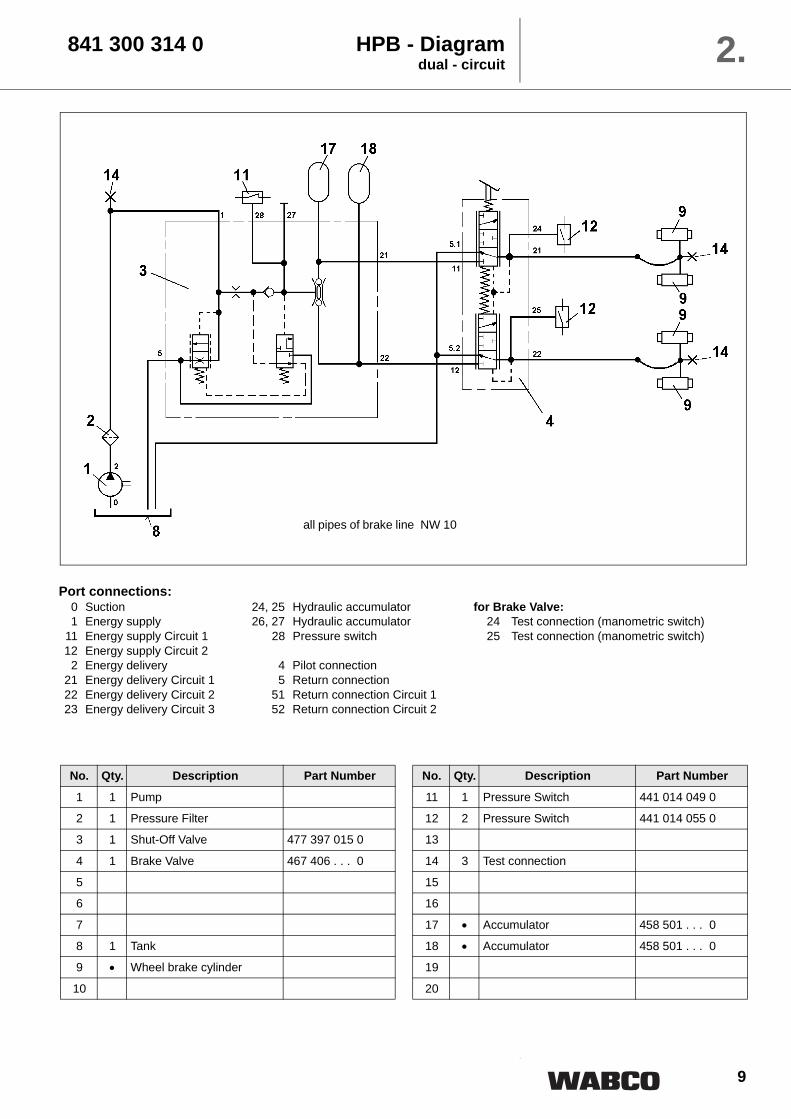
No. Qty. Description Part Number
1 1 Pump
2 1 Pressure Filter
3 1 Shut-Off Valve 477 397 . . . 0
4
5
6 1 Brake Valve 467 406 1 . . 0
7
8 1 Tank
9 • Wheel brake cylinder
10
No. Qty. Description Part Number
11 1 Pressure Switch 441 014 049 0
12 1 Pressure Switch 441 014 055 0
13
14 2 Test connection
15
16
17 • Accumulator 458 501 . . . 0
18
19
20
all pipes of brake line NW 10
Port connections:0 Suction1 Energy supply2 Energy delivery5 Return connection
9
No. Qty. Description Part Number
1 1 Pump
2 1 Pressure Filter
3 1 Shut-Off Valve 477 397 015 0
4 1 Brake Valve 467 406 . . . 0
5
6
7
8 1 Tank
9 • Wheel brake cylinder
10
No. Qty. Description Part Number
11 1 Pressure Switch 441 014 049 0
12 2 Pressure Switch 441 014 055 0
13
14 3 Test connection
15
16
17 • Accumulator 458 501 . . . 0
18 • Accumulator 458 501 . . . 0
19
20
841 300 314 0 HPB - Diagramdual - circuit 2.
all pipes of brake line NW 10
Port connections:0 Suction 24, 25 Hydraulic accumulator for Brake Valve:1 Energy supply 26, 27 Hydraulic accumulator 24 Test connection (manometric switch)
11 Energy supply Circuit 1 28 Pressure switch 25 Test connection (manometric switch)12 Energy supply Circuit 2
2 Energy delivery 4 Pilot connection21 Energy delivery Circuit 1 5 Return connection22 Energy delivery Circuit 2 51 Return connection Circuit 123 Energy delivery Circuit 3 52 Return connection Circuit 2
13
3.
Description of Components
14
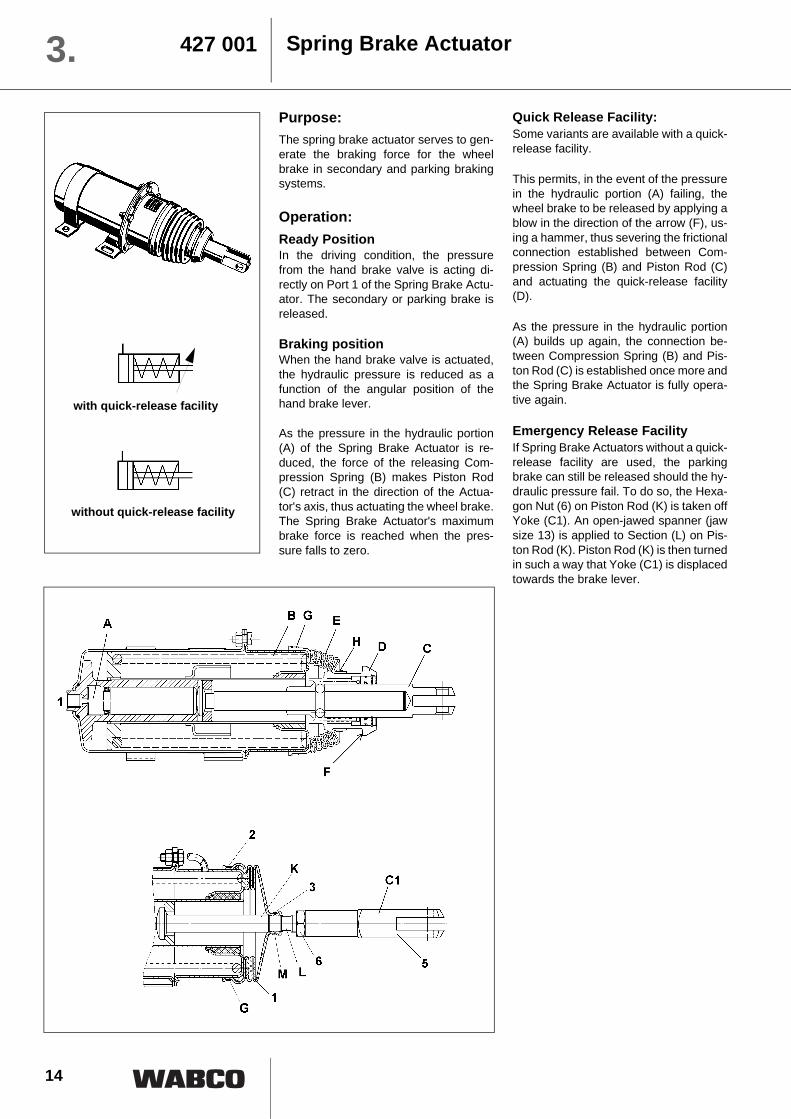
Spring Brake Actuator427 0013.Purpose:The spring brake actuator serves to gen-erate the braking force for the wheelbrake in secondary and parking brakingsystems.
Operation:Ready PositionIn the driving condition, the pressurefrom the hand brake valve is acting di-rectly on Port 1 of the Spring Brake Actu-ator. The secondary or parking brake isreleased.
Braking positionWhen the hand brake valve is actuated,the hydraulic pressure is reduced as afunction of the angular position of thehand brake lever.
As the pressure in the hydraulic portion(A) of the Spring Brake Actuator is re-duced, the force of the releasing Com-pression Spring (B) makes Piston Rod(C) retract in the direction of the Actua-tor's axis, thus actuating the wheel brake.The Spring Brake Actuator's maximumbrake force is reached when the pres-sure falls to zero.
Quick Release Facility:Some variants are available with a quick-release facility.
This permits, in the event of the pressurein the hydraulic portion (A) failing, thewheel brake to be released by applying ablow in the direction of the arrow (F), us-ing a hammer, thus severing the frictionalconnection established between Com-pression Spring (B) and Piston Rod (C)and actuating the quick-release facility(D).
As the pressure in the hydraulic portion(A) builds up again, the connection be-tween Compression Spring (B) and Pis-ton Rod (C) is established once more andthe Spring Brake Actuator is fully opera-tive again.
Emergency Release FacilityIf Spring Brake Actuators without a quick-release facility are used, the parkingbrake can still be released should the hy-draulic pressure fail. To do so, the Hexa-gon Nut (6) on Piston Rod (K) is taken offYoke (C1). An open-jawed spanner (jawsize 13) is applied to Section (L) on Pis-ton Rod (K). Piston Rod (K) is then turnedin such a way that Yoke (C1) is displacedtowards the brake lever.
with quick-release facility
without quick-release facility
15
Replacing the BellowsRemove clamps (2; 3 or H) from thebellows, replace as necessary whenfitting the new bellows. Pull off the faultybellows (1), push on new bellows andfasten with clamps (2; 3 or H).
Replacing the YokeWhen replacing the Yoke (5) onactuators without a quick-release facility,immobilize the piston rod (K) by applyinga spanner (jaw size 13). RemoveHexagon Nut (6) and unscrew Yoke (5)
from the piston rod. The new Yoke (5) isscrewed into the piston rod up to thepoint where the original piston rod lengthis once again achieved (see outlinedrawing: distance from centre yoke holeto end face of Port 1). Secure piston rodby means of hexagon nut.
Release pressure 87 ± 4 bar 60 -4 bar 40 ± 4bar 95 +6 bar 60 -4 bar
Operating temperature range –30°C to +80°C
Medium mineral oil 10 to 2000 mm2 /s
Output force at 0 mm stroke 2.75 kN 2.3 kN 1.5 kN 3.0 kN 2.3 kN
Output force at 80 mm stroke 4.32 kN 3.25 kN 2.2 kN 5.0 kN 3.25 kN
Piston rod deflection 3° on all sides
Emergency release facility NO NO NO YES YES
Yoke NO YES YES YES YES
Bellows YES YES YES YES YES
Weight 6.5 kg 6.8 kg 8.0 kg
Repair Kits:
Attention ! The enclosed portion of the actuator is spring-loaded !
For safety reasons the whole of the Spring Brake Actuator must bereplaced if parts other than those listed above are damaged.
Repair kit Variant of Actuator
427 001 002 2 427 001 007 0427 001 008 0
427 001 003 2 427 001 002 0427 001 005 0
16
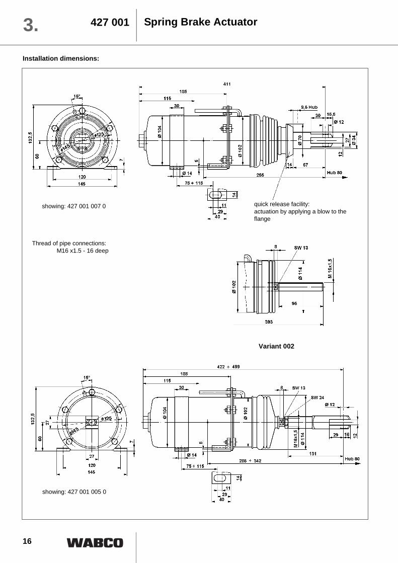
Spring Brake Actuator427 0013.Installation dimensions:
quick release facility:actuation by applying a blow to the flange
showing: 427 001 007 0
Variant 002
Thread of pipe connections:M16 x1.5 - 16 deep
showing: 427 001 005 0
17
Installation Requirements:The connecting lines must be installed insuch a way as to permit proper bleeding.The actuator should be mounted at aslight angle, its piston rod pointingdownwards.
Maintenance:No special maintenance beyond the legalrequirements is necessary.
When using high-pressure cleaners onthe vehicle, please make sure that thewater jet is not aimed directly at theSpring Brake Actuator (to prevent dam-aging the bellows)
Repair Work:When working on the brakingsystem, always make sure thatthere is absolutely no pressurein the system. Even when the engine isswitched off there will be someresidual pressure in the system!
When doing repair work, makesure your environment is veryclean. Immediately close all open portson the components and on pipesusing plugs!
Spring Brake Actuator 427 001 3.
18
Pressure Switch441 0143.Purpose:The Pressure Switches are used tovisually or audibly warn the driver of thepressure within the system.
Operation:Make Contact / Circuit CloserThe Pressure Switch can be fitted in thebraking system or directly on one of itscomponents. The system pressure actson an absorption area within the switch,making an electrical contact as thepressure on that area is increased. Theresulting current is used to activateawarning facility, for instance.
Break Contact / Circuit BreakerThe Pressure Switch can be fitted in thebraking system or directly on one of itscomponents. The system pressure actson an absorption area within the switch,
breaking an electrical contact as thepressure on that area is increased. Thecurrent is now broken, e.g. to deactivatea warning facility.
Installation Requirements:No special measures need to be taken.
Maintenance:No special maintenance beyond the legalrequirements is necessary. When using high-pressure cleaners onthe vehicle, please make sure that thewater jet is not directed at the PressureSwitch. (corrosion of contacts).
Breaking capacity of all pressure switches 100 Voltampere resistive load Boot for Pressure Switch: Part Number 897 750 342 4
19
Repair Work:
When working on the brakingsystem, always make sure thatthere is absolutely no pressurein the system. Even when the engine isswitched off there will be someresidual pressure in the system!
When doing repair work, makesure your environment is veryclean. Immediately close all open portson the components and on pipesusing plugs!
Installation dimensions:
Adjusting and testing the Pressure Switch:
The adjusting screw located between thetwo contact plugs can be set to thedesired value within a certain range. Foradjusting range, please refer to the table"Technical Data" on the previous page.
After making the adjustment, theadjusting screw should be secured usingwax or a similar material.
Pressure Switch 441 014 3.
For safety reasons the Pressure Switch needs to bereplaced as a whole if damaged.
Adjusting screw
20
Hydraulic Accumulator458 5013.Purpose:Fluids are practically incompressible andare thus incapable of accumulatingpressure energy. In hydropneumaticaccumulators, the compressibility of agas is utilized to accumulate fluid. Thecompressible medium used in theaccumulators is nitrogen.
In braking systems, the purpose of theaccumulators is to store the energysupplied by the hydrailc pump. They arealso used as an energy reserve when thepump is not working, as a compensatorfor any losses through leakage, and asoscillation dampers.
Operation:The accumulator consists of a fluidportion (A) and a gas portion (B) with a
diaphragm (C) as a gas-tight dividingelement. The fluid portion (A) isconnected to the hydraulic circuit,causing the diaphragm accumulator tobe filled and the gas volume to becompressed as the pressure rises. Whenthe pressure falls, the compressed gasvolume will expand, thus displacing theaccumulated pressure fluid into thecircuit.
The diaphragm bottom contains a valvedisk (D) which, if the diaphragmaccumulator is completely empty, closesthe hydraulic outlet, thus preventingdamage to the diaphragm.
Technical Data:
Part Number 458 501 071 0 458 501 101 0
Diameter 121 mm 136 mm
Mounting height 146 mm 160 mm
Nominal volume 0.75 dm³ 1.0 dm³
Priming pressure 50 bar
Operating medium mineral oil
Operating pressure 180 bar max. 200 bar max.
Thread M18x1.5 M22x1.5
Operating temperature range –30°C to +80°C
Mounting position optional
Priming gas nitrogen
21
The accumulators can be fitted in thehydraulic circuit, directly on a componentor in blocks on suitable consoles.
They should be fitted in as cool a locationas possible.Installation can be in any position.
Maintenance:No special maintenance beyond the legalrequirements is necessary.
The accumulator should be checkedannually. It should be replaced if theinitial gas pressure has fallen by morethan 30% (please refer to "Performance
testing and checking of theAccumulator").
Disposal of the Accumulator:Before the accumulator is scrapped, itsgas filling pressure must be reduced. Forthis purpose, drill a hole through GasChamber (B) using a drill approx. 3 mm indiameter. The gas chamber is located onthe side opposite the threaded portabove the welding seam around thecentre of the accumulator.Wear safety goggles when doing thisjob!
Installation Requirements:
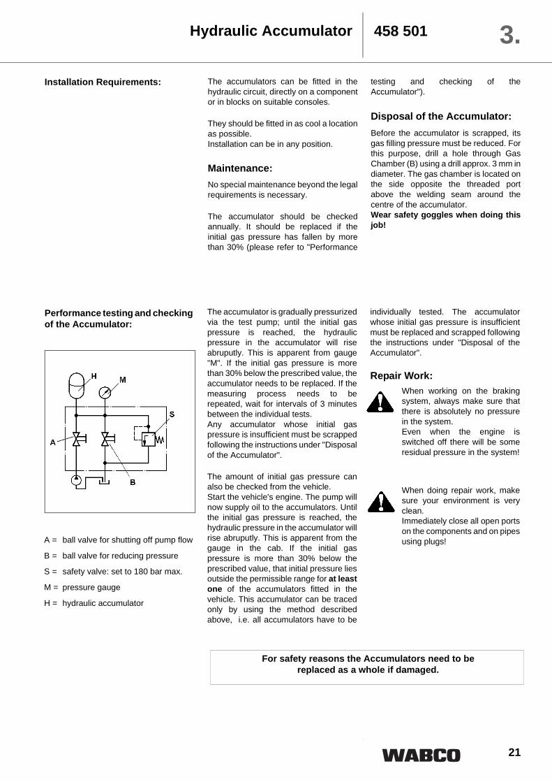
Performance testing and checking of the Accumulator:
Hydraulic Accumulator 458 501 3.
The accumulator is gradually pressurizedvia the test pump; until the initial gaspressure is reached, the hydraulicpressure in the accumulator will riseabruputly. This is apparent from gauge"M". If the initial gas pressure is morethan 30% below the prescribed value, theaccumulator needs to be replaced. If themeasuring process needs to berepeated, wait for intervals of 3 minutesbetween the individual tests. Any accumulator whose initial gaspressure is insufficient must be scrappedfollowing the instructions under "Disposalof the Accumulator".
The amount of initial gas pressure canalso be checked from the vehicle.Start the vehicle's engine. The pump willnow supply oil to the accumulators. Untilthe initial gas pressure is reached, thehydraulic pressure in the accumulator willrise abruputly. This is apparent from thegauge in the cab. If the initial gaspressure is more than 30% below theprescribed value, that initial pressure liesoutside the permissible range for at leastone of the accumulators fitted in thevehicle. This accumulator can be tracedonly by using the method describedabove, i.e. all accumulators have to be
individually tested. The accumulatorwhose initial gas pressure is insufficientmust be replaced and scrapped followingthe instructions under "Disposal of theAccumulator".
Repair Work:When working on the brakingsystem, always make sure thatthere is absolutely no pressurein the system. Even when the engine isswitched off there will be someresidual pressure in the system!
When doing repair work, makesure your environment is veryclean. Immediately close all open portson the components and on pipesusing plugs!
For safety reasons the Accumulators need to be replaced as a whole if damaged.
A = ball valve for shutting off pump flow
B = ball valve for reducing pressure
S = safety valve: set to 180 bar max.
M = pressure gauge
H = hydraulic accumulator
22
Brake Valvefor single circuit braking system
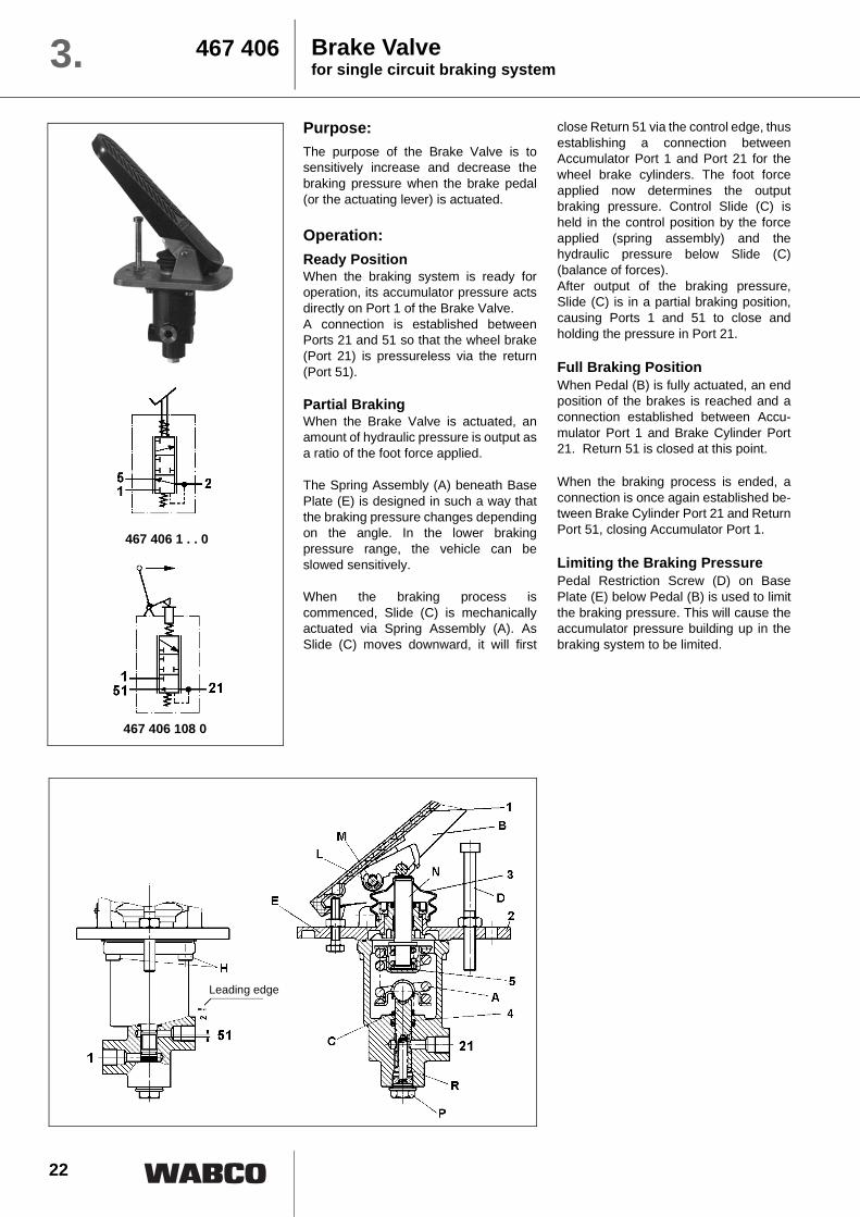
467 4063.Purpose:The purpose of the Brake Valve is tosensitively increase and decrease thebraking pressure when the brake pedal(or the actuating lever) is actuated.
Operation:Ready PositionWhen the braking system is ready foroperation, its accumulator pressure actsdirectly on Port 1 of the Brake Valve. A connection is established betweenPorts 21 and 51 so that the wheel brake(Port 21) is pressureless via the return(Port 51).
Partial BrakingWhen the Brake Valve is actuated, anamount of hydraulic pressure is output asa ratio of the foot force applied.
The Spring Assembly (A) beneath BasePlate (E) is designed in such a way thatthe braking pressure changes dependingon the angle. In the lower brakingpressure range, the vehicle can beslowed sensitively.
When the braking process iscommenced, Slide (C) is mechanicallyactuated via Spring Assembly (A). AsSlide (C) moves downward, it will first
close Return 51 via the control edge, thusestablishing a connection betweenAccumulator Port 1 and Port 21 for thewheel brake cylinders. The foot forceapplied now determines the outputbraking pressure. Control Slide (C) isheld in the control position by the forceapplied (spring assembly) and thehydraulic pressure below Slide (C)(balance of forces). After output of the braking pressure,Slide (C) is in a partial braking position,causing Ports 1 and 51 to close andholding the pressure in Port 21.
Full Braking PositionWhen Pedal (B) is fully actuated, an endposition of the brakes is reached and aconnection established between Accu-mulator Port 1 and Brake Cylinder Port21. Return 51 is closed at this point.
When the braking process is ended, aconnection is once again established be-tween Brake Cylinder Port 21 and ReturnPort 51, closing Accumulator Port 1.
Limiting the Braking PressurePedal Restriction Screw (D) on BasePlate (E) below Pedal (B) is used to limitthe braking pressure. This will cause theaccumulator pressure building up in thebraking system to be limited.
467 406 108 0
467 406 1 . . 0
Leading edge
23
showing: 467 406 108 0
showing: 467 406 108 0
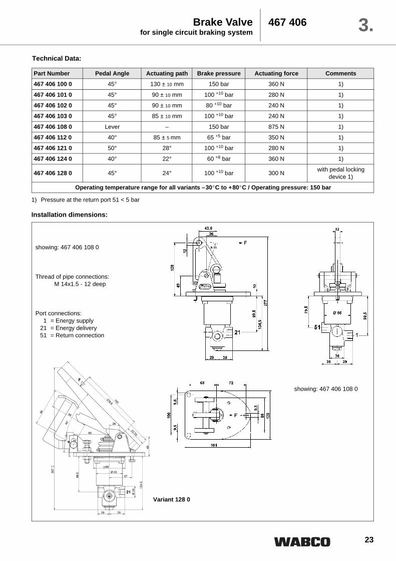
Thread of pipe connections:M 14x1.5 - 12 deep
Port connections:1 = Energy supply
21 = Energy delivery51 = Return connection
Variant 128 0
Technical Data:
Brake Valvefor single circuit braking system
467 406 3.
Part Number Pedal Angle Actuating path Brake pressure Actuating force Comments
467 406 100 0 45° 130 ± 10 mm 150 bar 360 N 1)
467 406 101 0 45° 90 ± 10 mm 100 +10 bar 280 N 1)
467 406 102 0 45° 90 ± 10 mm 80 +10 bar 240 N 1)
467 406 103 0 45° 85 ± 10 mm 100 +10 bar 240 N 1)
467 406 108 0 Lever – 150 bar 875 N 1)
467 406 112 0 40° 85 ± 5 mm 65 +5 bar 350 N 1)
467 406 121 0 50° 28° 100 +10 bar 280 N 1)
467 406 124 0 40° 22° 60 +8 bar 360 N 1)
467 406 128 0 45° 24° 100 +10 bar 300 N with pedal locking device 1)
Operating temperature range for all variants –30°C to +80°C / Operating pressure: 150 bar
1) Pressure at the return port 51 < 5 bar
Installation dimensions:
24
Brake Valvefor single circuit braking system
467 4063.
Return Line 51 must be connecteddirectly to the tank. The connecting linesmust be installed in such a way as topermit proper bleeding.
Maintenance of the Brake ValveNo special maintenance beyond the legalrequirements is necessary.
When using high-pressure cleaners onthe vehicle, please make sure that thewater jet is not aimed directly at theBrake Valve. (to prevent damaging thebellows)
Replacing the Pedal CoverPedal Cover (1) is simply pulled off byhand. The new pedal cover is pushed
over Pedal (B) and tightened manually.Fasten the bellows with the strapretainers.
Replacing the complete ActuatingMechanism
Carefully clamp the unit vertically in afixture. The actuating mechanism can beremoved by taking out the four Screws(H) below Base Plate (E). Make sure thatSpring Assembly (A) does not fall out.When installing the new actuatingmechanism, make sure that SpringAssembly (A) is fitted in the right order. Tighten the four Screws (H).
Installation dimensions:
showing: 467 406 102 0
Thread of pipe connections:
Port connections:1 = Energy supply
21 = Energy delivery24 = Test port 51 = Return connection
Installation Requirements:
Variant 1, 21 and 51 24100 M 14x1.5 -12 deep M 12x1.5101, 102, 108, 128 M 14x1.5 -12 deep –
124 M 16x1.5 -12 deep M 12x1.5121 M 16x1.5 -12 deep M 10x1
25
Replacing the BellowsTo change Bellows (3) it is advisable toremove Pedal (B). For this purpose,loosen Retaining Ring (L) and knock outBolt (M) using a mandril. When knockingout the bolt, make sure that the mandril isapplied to the side of the bolt without aknurl. Remove Pedal (B) and Bellows (3).Now fit the new Bellows (3) and proceedin reverse order as described above. Theupper portion of Bellows (3) is fastened toPiston (N), its lower portion to Base Plate(E).
Replacing the Grooved RingCarefully clamp the unit vertically in afixture. Unscrew Screw Plug (P) and pullSlide (C) out downwards. Check the slidefor damage. If they are found to bedamaged, the whole Brake Valve needsto be replaced. (Pairs of slides andhousings are matched in manufacturing.)If the slide is not damaged in any way,remove the whole actuating mechanism
as described above. Remove SpringAssembly (A) and Grooved Ring (4) andput in a new greased grooved ring with itslips pointing downwards. Install both thespring assembly as shown in thedrawing, and the pedal. Carefully re-insert Slide (C) into the housing frombelow, turning it slightly. Put in Spring (R)and close the unit with Screw Plug (P).Check Return Port 51 to see if there is agap of approx. 2 mm between the loweredge of the hole and the control edge ofSlide (C). If this is not the case, changethe setting by removing or addingdistance washers (5) in the upper springplate of the spring assembly. Check thedistance between the lower edge of thehole and the control edge of Slide (C)again.
Spare parts: Description No. Part Number Variant of Brake Valve
complete Actuating Mechanism
2 467 406 782 2 101, 102, 103
2 467 406 791 2 112, 124
Bellows 3 897 754 865 4 112, 121, 124
Repair kit Variant of Brake Valve
467 406 004 2 467 406 102 0
Repair Work:
Brake Valvefor single circuit braking system
467 406 3.
For safety reasons the whole of the Brake Valve must be replaced if parts other than those listed above are damaged.
When working on the brakingsystem, always make sure thatthere is absolutely no pressurein the system. Even when the engine isswitched off there will be someresidual pressure in the system!
When doing repair work, makesure your environment is veryclean. Immediately close all open portson the components and on pipesusing plugs!
26
Brake Valvefor dual circuit braking system
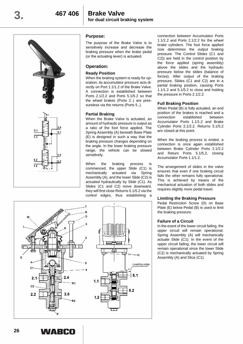
467 4063.Purpose:The purpose of the Brake Valve is tosensitively increase and decrease thebraking pressure when the brake pedal(or the actuating lever) is actuated.
Operation:Ready PositionWhen the braking system is ready for op-eration, its accumulator pressure acts di-rectly on Port 1.1/1.2 of the Brake Valve.A connection is established betweenPorts 2.1/2.2 and Ports 5.1/5.2 so thatthe wheel brakes (Ports 2..) are pres-sureless via the returns (Ports 5..).
Partial BrakingWhen the Brake Valve is actuated, anamount of hydraulic pressure is output asa ratio of the foot force applied. TheSpring Assembly (A) beneath Base Plate(E) is designed in such a way that thebraking pressure changes depending onthe angle. In the lower braking pressurerange, the vehicle can be slowedsensitively.
When the braking process iscommenced, the upper Slide (C1) ismechanically actuated via SpringAssembly (A), and the lower Slide (C2) isactuated hydraulically by Slide (C1). AsSlides (C1 and C2) move downward,they will first close Returns 5.1/5.2 via thecontrol edges, thus establishing a
connection between Accumulator Ports1.1/1.2 and Ports 2.1/2.2 for the wheelbrake cylinders. The foot force appliednow determines the output brakingpressure. The Control Slides (C1 andC2)) are held in the control position bythe force applied (spring assembly)above the slides and the hydraulicpressure below the slides (balance offorces). After output of the brakingpressure, Slides (C1 and C2) are in apartial braking position, causing Ports1.1/1.2 and 5.1/5.2 to close and holdingthe pressure in Ports 2.1/2.2.
Full Braking PositionWhen Pedal (B) is fully actuated, an endposition of the brakes is reached and aconnection established betweenAccumulator Ports 1.1/1.2 and BrakeCylinder Ports 2.1/2.2. Returns 5.1/5.2are closed at this point.
When the braking process is ended, aconnection is once again establishedbetween Brake Cylinder Ports 2.1/2.2and Return Ports 5.1/5.2, closingAccumulator Ports 1.1/1.2.
The arrangement of slides in the valveensures that even if one braking circuitfails the other remains fully operational.This is achieved by means of themechanical actuation of both slides andrequires slightly more pedal travel.
Limiting the Braking PressurePedal Restriction Screw (D) on BasePlate (E) below Pedal (B) is used to limitthe braking pressure.
Failure of a CircuitIn the event of the lower circuit failing, theupper circuit will remain operational.Spring Assembly (A) will mechanicallyactuate Slide (C1). In the event of theupper circuit failing, the lower circuit willremain operational since the lower Slide(C2) is mechanically actuated by SpringAssembly (A) and Slice (C1).
Leading edge
27
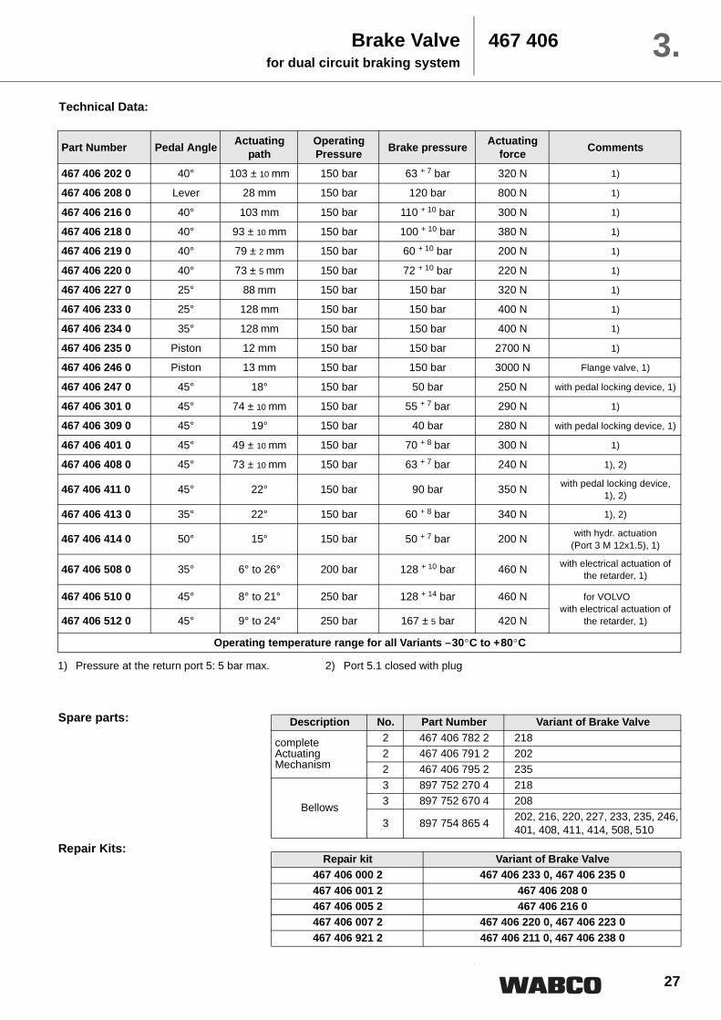
Technical Data:
Spare parts:
Repair Kits:
Brake Valvefor dual circuit braking system
467 406 3.
1) Pressure at the return port 5: 5 bar max. 2) Port 5.1 closed with plug
Part Number Pedal Angle Actuating path
Operating Pressure Brake pressure Actuating
force Comments
467 406 202 0 40° 103 ± 10 mm 150 bar 63 + 7 bar 320 N 1)
467 406 208 0 Lever 28 mm 150 bar 120 bar 800 N 1)
467 406 216 0 40° 103 mm 150 bar 110 + 10 bar 300 N 1)
467 406 218 0 40° 93 ± 10 mm 150 bar 100 + 10 bar 380 N 1)
467 406 219 0 40° 79 ± 2 mm 150 bar 60 + 10 bar 200 N 1)
467 406 220 0 40° 73 ± 5 mm 150 bar 72 + 10 bar 220 N 1)
467 406 227 0 25° 88 mm 150 bar 150 bar 320 N 1)
467 406 233 0 25° 128 mm 150 bar 150 bar 400 N 1)
467 406 234 0 35° 128 mm 150 bar 150 bar 400 N 1)
467 406 235 0 Piston 12 mm 150 bar 150 bar 2700 N 1)
467 406 246 0 Piston 13 mm 150 bar 150 bar 3000 N Flange valve, 1)
467 406 247 0 45° 18° 150 bar 50 bar 250 N with pedal locking device, 1)
467 406 301 0 45° 74 ± 10 mm 150 bar 55 + 7 bar 290 N 1)
467 406 309 0 45° 19° 150 bar 40 bar 280 N with pedal locking device, 1)
467 406 401 0 45° 49 ± 10 mm 150 bar 70 + 8 bar 300 N 1)
467 406 408 0 45° 73 ± 10 mm 150 bar 63 + 7 bar 240 N 1), 2)
467 406 411 0 45° 22° 150 bar 90 bar 350 N with pedal locking device, 1), 2)
467 406 413 0 35° 22° 150 bar 60 + 8 bar 340 N 1), 2)
467 406 414 0 50° 15° 150 bar 50 + 7 bar 200 N with hydr. actuation (Port 3 M 12x1.5), 1)
467 406 508 0 35° 6° to 26° 200 bar 128 + 10 bar 460 N with electrical actuation of the retarder, 1)
467 406 510 0 45° 8° to 21° 250 bar 128 + 14 bar 460 N for VOLVO with electrical actuation of
the retarder, 1)467 406 512 0 45° 9° to 24° 250 bar 167 ± 5 bar 420 N
Operating temperature range for all Variants –30°C to +80°C
Description No. Part Number Variant of Brake Valve
Port connections:1.1, 1.2 = Hydraulic accumulator2.1, 2.2 = Service brake2.4, 2.5 = Test connection5.1, 5.2 = Return connection
showing: 467 406 246 0
Brake Valvefor dual circuit braking system
467 406 3.
30
Brake Valvefor dual circuit braking system
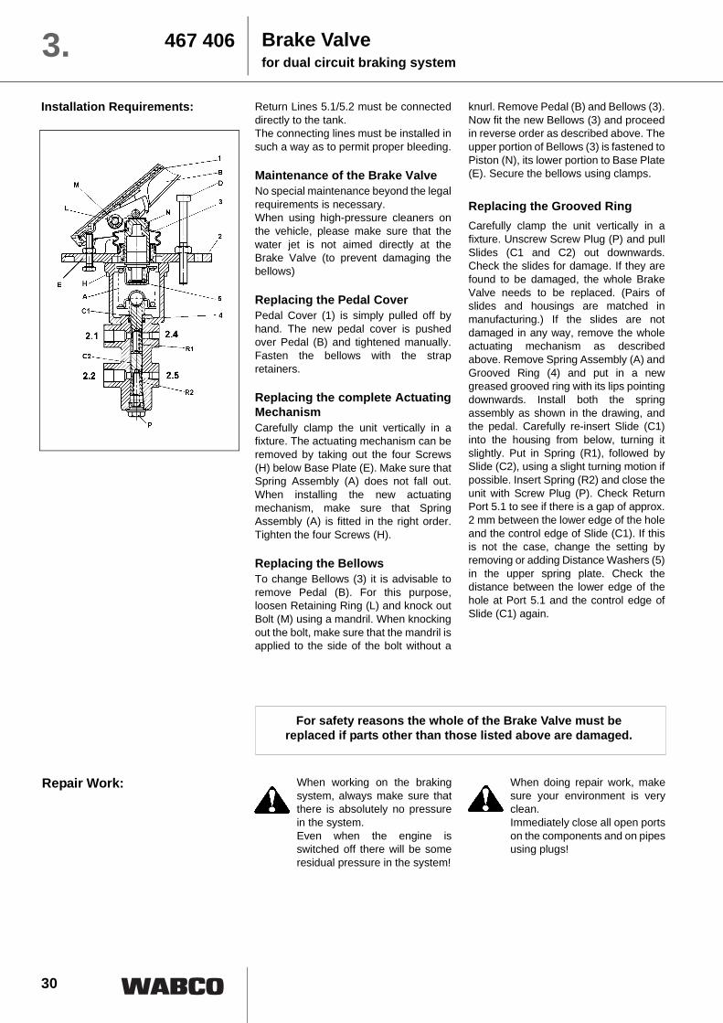
467 4063.Return Lines 5.1/5.2 must be connecteddirectly to the tank. The connecting lines must be installed insuch a way as to permit proper bleeding.
Maintenance of the Brake ValveNo special maintenance beyond the legalrequirements is necessary. When using high-pressure cleaners onthe vehicle, please make sure that thewater jet is not aimed directly at theBrake Valve (to prevent damaging thebellows)
Replacing the Pedal CoverPedal Cover (1) is simply pulled off byhand. The new pedal cover is pushedover Pedal (B) and tightened manually.Fasten the bellows with the strapretainers.
Replacing the complete ActuatingMechanismCarefully clamp the unit vertically in afixture. The actuating mechanism can beremoved by taking out the four Screws(H) below Base Plate (E). Make sure thatSpring Assembly (A) does not fall out.When installing the new actuatingmechanism, make sure that SpringAssembly (A) is fitted in the right order.Tighten the four Screws (H).
Replacing the BellowsTo change Bellows (3) it is advisable toremove Pedal (B). For this purpose,loosen Retaining Ring (L) and knock outBolt (M) using a mandril. When knockingout the bolt, make sure that the mandril isapplied to the side of the bolt without a
knurl. Remove Pedal (B) and Bellows (3).Now fit the new Bellows (3) and proceedin reverse order as described above. Theupper portion of Bellows (3) is fastened toPiston (N), its lower portion to Base Plate(E). Secure the bellows using clamps.
Replacing the Grooved RingCarefully clamp the unit vertically in afixture. Unscrew Screw Plug (P) and pullSlides (C1 and C2) out downwards.Check the slides for damage. If they arefound to be damaged, the whole BrakeValve needs to be replaced. (Pairs ofslides and housings are matched inmanufacturing.) If the slides are notdamaged in any way, remove the wholeactuating mechanism as describedabove. Remove Spring Assembly (A) andGrooved Ring (4) and put in a newgreased grooved ring with its lips pointingdownwards. Install both the springassembly as shown in the drawing, andthe pedal. Carefully re-insert Slide (C1)into the housing from below, turning itslightly. Put in Spring (R1), followed bySlide (C2), using a slight turning motion ifpossible. Insert Spring (R2) and close theunit with Screw Plug (P). Check ReturnPort 5.1 to see if there is a gap of approx.2 mm between the lower edge of the holeand the control edge of Slide (C1). If thisis not the case, change the setting byremoving or adding Distance Washers (5)in the upper spring plate. Check thedistance between the lower edge of thehole at Port 5.1 and the control edge ofSlide (C1) again.
Installation Requirements:
Repair Work:
For safety reasons the whole of the Brake Valve must be replaced if parts other than those listed above are damaged.
When working on the brakingsystem, always make sure thatthere is absolutely no pressurein the system. Even when the engine isswitched off there will be someresidual pressure in the system!
When doing repair work, makesure your environment is veryclean. Immediately close all open portson the components and on pipesusing plugs!
31
Purpose:The purpose of the Hand Brake Valve isto sensitively increase and decrease thebraking pressure when the hand brakelever is actuated.
Operation:Ready PositionWhen the braking system is ready foroperation, its accumulator pressure actsdirectly on Port 1 of the Hand BrakeValve. A connection is establishedbetween Ports 1 and 21 so that thevehicle's hand brake is released.
Secondary Braking SystemWhen the Hand Brake Valve is actuated,the hydraulic release pressure isincreased or decreased as a function ofthe hand brake lever's pivoting angle.Spring Assembly (A) below Cam Plate(B) permits a sensitive braking processfor the vehicle.
When the secondary braking process iscommenced, Slide (C) is mechanicallyactuated via Spring Assembly (A). Slide(C) moves upwards, it first closesAccumulator Port 1 via the control edgeand then establishes a connection
between Brake Cylinder Port 2 andReturn 5. The pivoting angle of the handbrake lever will now determine thepressure in the spring brake actuator(Port 2). Slide (C) is held in the controlposition by the force (spring assembly)above the slide and by the hydraulicpressure below the slide (balance offorces). Slide C is in a partial brakingposition, causing Ports 1 and 5 to closeand to hold the pressure in Port 2.
In the range of partial brake application,the hand lever will automatically return tothe driving position when the brakingprocess is ended.
Parking BrakeWhen the lever is fully actuated, an endposition of the brake is reached and aconnection is established betweenReturn 5 and Brake Cylinder Port 2.Accumulator Port 1 is closed and thelever is locked in position. When theparking brake is released, a connectionbetween Brake Cylinder Port 2 andAccumulator Port 1 is once moreestablished, and Return Port 5 is closed.Once released from its locked position,the hand brake lever will automaticallyreturn to the driving position.
Hand Brake Valve 467 410 3.
(Locked position = pressure reduc
Installation Requirements:Return Line 5 must be connected directlyto the tank. The connecting lines must be installed insuch a way as to permit proper bleeding.The Hand Brake Valve should beinstalled in a position where it cannot beaccidentally actuated by the driver's foot.
Maintenance of the Brake ValveNo special maintenance beyond the legalrequirements is necessary.
When using high-pressure cleaners onthe vehicle, please make sure that thewater jet is not aimed directly at the HandBrake Valve (to prevent damaging thebellows)
Repair Work:When working on the brakingsystem, always make sure thatthere is absolutely no pressurein the system. Even when the engine isswitched off there will be someresidual pressure in the system!
When doing repair work, makesure your environment is veryclean. Immediately close all open portson the components and on pipesusing plugs!
Replacing the BellowsTo change Bellows (D), removeActuating Button (E) from Lever (F). Todo this, push out the two Retaining Pins(G). The Bellows (D) can now be pulledoff and the new ones installed. PushActuating Button (E) back onto Lever (F),securing it with Retaining Pins (G).
32
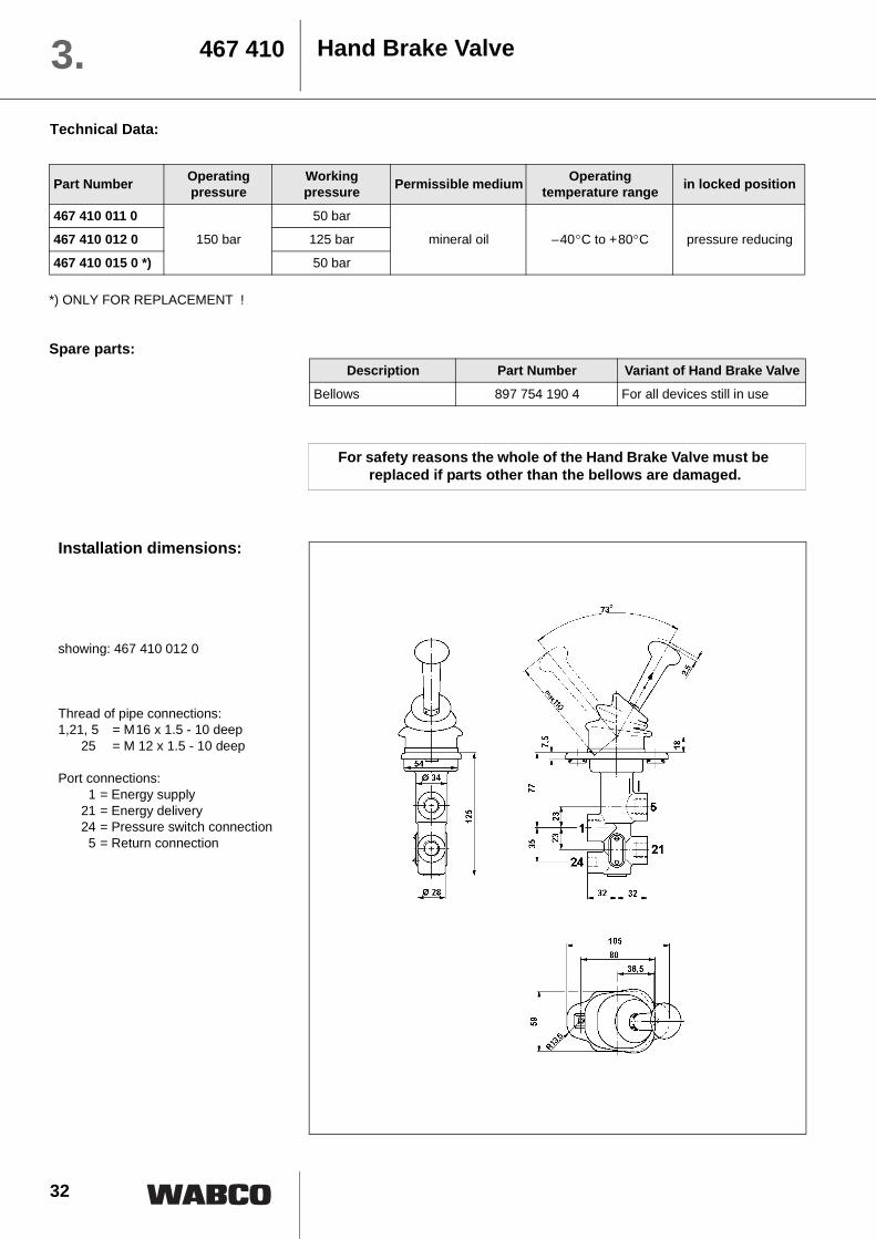
Hand Brake Valve467 4103.Technical Data:
*) ONLY FOR REPLACEMENT !
Spare parts:
Part Number Operating pressure
Working pressure Permissible medium Operating
temperature range in locked position
467 410 011 0
150 bar
50 bar
mineral oil –40°C to +80°C pressure reducing467 410 012 0 125 bar
467 410 015 0 *) 50 bar
Description Part Number Variant of Hand Brake Valve
Bellows 897 754 190 4 For all devices still in use
For safety reasons the whole of the Hand Brake Valve must be replaced if parts other than the bellows are damaged.
Installation dimensions:
showing: 467 410 012 0
Thread of pipe connections:1,21, 5 = M16 x 1.5 - 10 deep
The purpose of the Double Check Valveis to permit alternate actuation of thebraking circuits. It permits a hydraulicbraking circuit to be actuated by twoactuating valves.
Operation:
When the control pressure is built up, thecontrol pressure is passed unrestrictedly
from Port 11 or 12, depending on the typeof actuation of the valve, to Port 2. A ballseat valve arrangement ensures that asthe foot brake valve is actuated, Port 12remains pressureless when the pressureis increased at Port 11, and vice versa.The ball seat also prevents the controlpressure being reduced through the partof the line which is not being utilized.
NO LONGER AVAILABLE ! ONLY FOR INFORMATION !
Installation dimensions:
Thread of pipe connections:M 14 x 1.5 DIN 74 235
Port connections:11, 12 = Energy supply
2 = Energy delivery
Technical data
Part Number 476 399 001 0 478 399 002 0
Operating pressure 200 bar max., 2 bar min.
Permissible medium mineral oil10 mm²/s to 1936 mm²/s brake fluid
Operating temperaturerange –40°C to +80°C
Rate of flow max. 12 dm³ / min
Weight 0.42 kg
Maintenance of the Double CheckValveNo special maintenance beyond the legalrequirements is necessary.
Repair Work:When working on the brakingsystem, always make sure thatthere is absolutely no pressurein the system.
Even when the engine isswitched off there will be someresidual pressure in the system!
When doing repair work, makesure your environment is veryclean. Immediately close all open portson the components and on pipesusing plugs!
Double check valve 476 399478 399 3.
34
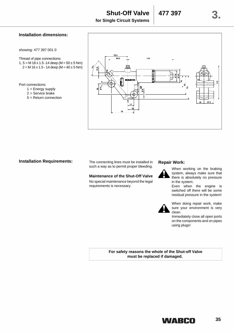
Shut-Off Valvefor Single Circuit Systems
477 3973.Purpose:The purpose of the Shut-Off Valve is tocontrol the pressure level in theaccumulators.
Operation:Ready PositionWhen the braking system is ready foroperation (i.e. the accumulators arecharged) the pump stream is present atPort 1 of the Shut-Off Valve. Aconnection is established between Ports1 and 5 so that the pump stream can,with a small difference in pressures, bereturned directly to the reservoir or otherconsumers. The rear of Main Slide (A) ispressureless. The pressure within thebraking system will hold Control Slide (B)in its locked position (E1) in which therear of Main Slide (A) is directlyconnected to Return 5 via Hole (G). Check Valve (C) in the hole to Port 2secures the accumulator pressures.
Charging Process
As the accumulator pressure falls to thepreset value, Control Slide (B) will,through the force of Spring Assembly(D), overcome its locked position (E1)and move to another locked position(E2). Via Orifice (F) and throughConnecting Hole (H), an oil stream flowsto the rear of Main Slide (A). Thepressure building up at the rear of MainSlide (A) and the pressure present belowMain Slide (A) put Main Slide (A) in afloating position, permitting a partialstream to continue to reach Port 5 andthe remaining stream to flow to Port 2 viaCheck Valve (C) until the pressure at Port2 is approx. 150 bar. Control Slide (B) willthen once again move to Locked Position(E1) in which a connection is establishedbetween Ports 1 and 5 and the whole ofthe pump stream once again flows to thereservoir. Check Valve (C) once againsecures the accumulator pressures.
Technical Data: Part Number 477 397 001 0 477 397 011 0 477 397 031 0
Operating pressure 200 bar max.
Pressure at port 5 200 bar max. 200 bar max. 50 bar max.
Cut-in pressure 120 +10 bar 120 +10 bar 120 +10 bar
Cut-off pressure 150 -10 bar 150 -10 bar 150 -10 bar
Flow rate max. 16 l /min from 1 ⇒ 2 = 2...3 l /minfrom 1 ⇒ 5 = 45 l /min
from 1⇒ 2 = 17...19 l /minfrom 1 ⇒ 5 = 45 l /min
Permissible medium mineral oil: 10 . . . 1940 mm² /s
Operating temperaturerange
–30°C to +80°C
Weight 2.4 kg
35
Installation dimensions:
showing: 477 397 001 0
Thread of pipe connections:1, 5 = M 18 x 1.5 -14 deep (M = 50 ± 5 Nm) 2 = M 16 x 1.5 - 14 deep (M = 40 ± 5 Nm)
Port connections:1 = Energy supply2 = Service brake5 = Return connection
Shut-Off Valvefor Single Circuit Systems
477 397 3.
Installation Requirements: The connecting lines must be installed insuch a way as to permit proper bleeding.
Maintenance of the Shut-Off ValveNo special maintenance beyond the legalrequirements is necessary.
Repair Work:When working on the brakingsystem, always make sure thatthere is absolutely no pressurein the system. Even when the engine isswitched off there will be someresidual pressure in the system!
When doing repair work, makesure your environment is veryclean. Immediately close all open portson the components and on pipesusing plugs!
For safety reasons the whole of the Shut-off Valve must be replaced if damaged.
36
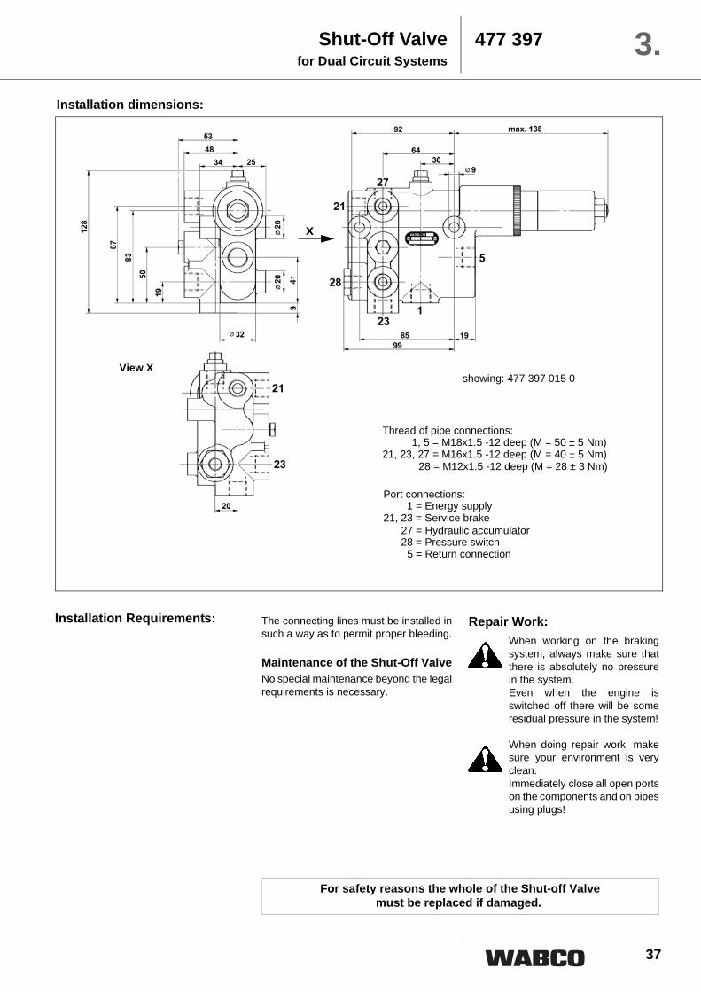
Shut-Off Valvefor Dual Circuit Systems
477 3973.Purpose:The purpose of the Shut-Off Valve is tocontrol the pressure level in theaccumulators.
Operation:Ready PositionWhen the braking system is ready foroperation (i.e. the accumulators arecharged) the pump stream is present atPort 1 of the Shut-Off Valve. Aconnection is established between Ports1 and 5 so that the pump stream is, witha small difference in pressures, returneddirectly to the reservoir. The rear of MainSlide (A) is pressureless.
The pressure within the braking systemwill hold Control Slide (B ) in its lockedposition (E1) in which the rear of MainSlide (A) is directly connected to Return5 via Hole (G). Check Valve (D) in thehole to Ports 21 and 23 secures theaccumulator pressures. Shuttle Valve (H)causes the accumulator with the lowestpressure to operate the Shut-Off Valvewhilst securing the circuit in the event ofa broken pipe.
Charging ProcessAs the accumulator pressure falls to thepreset value, Control Slide (B) will,through the force of Spring Assembly(C), overcome its locked position (E1)and move to another locked position(E2). Via Orifice (F) an oil stream flows tothe rear of Main Slide (A). The pressurebuilding up at the rear of Main Slide (A)and the pressure present below MainSlide (A) put Main Slide (A) in a floatingposition, permitting a partial stream tocontinue to reach Port 5 and theremaining stream to flow to Ports 21/23via Check Valve (D) until the pressurewithin the braking system is approx. 150bar. Control Slide (B) will then once againmove to Locked Position (E1) in which aconnection is established between Ports1 and 5. The whole of the pump streamonce again flows to the reservoir via Port5. Check Valve (D) once again securesthe accumulator pressures.
Technical Data: Part Number 477 397 015 0
Operating pressure 200 bar max.
Pressure at port 5 temporary 200 bar
Cut-in pressure 120 +8 bar
Cut-off pressure 150 -8 bar
Rate of flow max. 45 l /min
Permissible medium mineral oil: 2000 to 10 mm² /sVAI 6 to 12
Operating range 20 +10 bar
Operating temperature range –30°C to +80°C
Weight 3.8 kg
37
Installation dimensions:
Shut-Off Valvefor Dual Circuit Systems
477 397 3.
Installation Requirements: The connecting lines must be installed insuch a way as to permit proper bleeding.
Maintenance of the Shut-Off ValveNo special maintenance beyond the legalrequirements is necessary.
Repair Work:When working on the brakingsystem, always make sure thatthere is absolutely no pressurein the system. Even when the engine isswitched off there will be someresidual pressure in the system!
When doing repair work, makesure your environment is veryclean. Immediately close all open portson the components and on pipesusing plugs!
For safety reasons the whole of the Shut-off Valve must be replaced if damaged.
View X
x
showing: 477 397 015 0
Thread of pipe connections:1, 5 = M18x1.5 -12 deep (M = 50 ± 5 Nm)
477 3973.Purpose:The purpose of the Shut-Off Valve is tocontrol the pressure level in theaccumulators.
Operation:Ready PositionWhen the braking system is ready foroperation (i.e. the accumulators arecharged) the pump stream is present atPort 1 of the Shut-Off Valve. Aconnection is established between Ports1 and 5 so that the pump stream is, witha small difference in pressures, returneddirectly to the reservoir. The rear of MainSlide (A) is pressureless. The pressurewithin the braking system will holdControl Slide (B ) in its locked position(E1) in which the rear of Main Slide (A) isdirectly connected to Return 5 via Hole(G). Check Valve (D) in the hole to Port27 secures the accumulator pressure ofthe operating accumulator. This isavailable as an additional braking volumefor the braking system, preventingexcessively frequent actuation of theShut-Off Valve in the event of a leakage.Shuttle Valves (H) additionally secureeach braking circuit against pressurelosses in the event of a broken pipe.
Charging ProcessAs the accumulator pressure falls to thepreset value, Control Slide (B) will,through the force of Spring Assembly(C), overcome its locked position (E1)and move to another locked position(E2). Via Orifice (F) an oil stream flows tothe rear of Main Slide (A). The pressurebuilding up at the rear of Main Slide (A)and the pressure present below MainSlide (A) put Main Slide (A) in a floatingposition, permitting a partial stream tocontinue to reach Port 5 and theremaining stream to flow to Ports 21//22/23 via Check Valve (D) until the pressurewithin the braking system is approx. 150bar. Control Slide (B) will then once againmove to Locked Position (E1) in which aconnection is established between Ports1 and 5. The whole of the pump streamonce again flows to the reservoir via Port5. Check Valve (D) again secures theaccumulator pressures.Variant 007
Variant 014
39
Shut-Off Valvefor Triple Circuit Systems
477 397 3.Part Number 477 397 007 0 477 397 014 0
Pressure at port 5 – temporary200 bar max.
Pressure limiting 170 + 30 bar without
Cut-in pressure 120 + 8 bar
Cut-off pressure 150 - 8 bar
Flow rate max. 16 l /min 45 l /min
Flow rate to braking circuit 3 + 1 l /min 3 + 1 l /min
Permissible medium mineral oil 10 ... 2000 mm² /s
Operating temperature range –30°C to +80°C
Weight 3.8 kg
Technical Data:
Installation dimensions:
View X
x
showing: 477 397 014 0
Thread of pipe connections:1, 5 = M18x1.5 -12 deep (M = 50 ± 5 Nm)
For safety reasons the whole of the Shut-off Valve must be replaced if damaged.
The connecting lines must be installed insuch a way as to permit proper bleeding.Maintenance of the Shut-Off ValveNo special maintenance beyond the legalrequirements is necessary.
Repair Work:
When working on the brakingsystem, always make sure thatthere is absolutely no pressurein the system. Even when the
engine is switched off there willbe some residual pressure in thesystem!
When doing repair work, makesure your environment is veryclean. Immediately close all open portson the components and on pipesusing plugs!
40
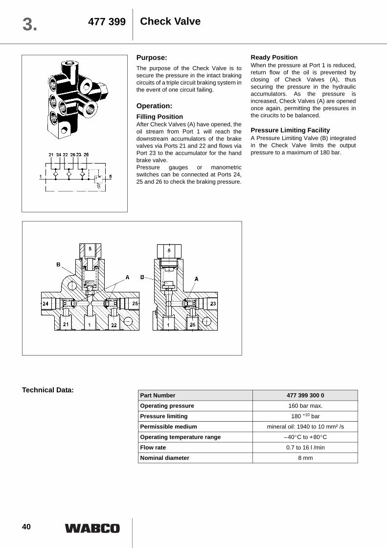
Check Valve477 3993.Purpose:The purpose of the Check Valve is tosecure the pressure in the intact brakingcircuits of a triple circuit braking system inthe event of one circuit failing.
Operation:Filling PositionAfter Check Valves (A) have opened, theoil stream from Port 1 will reach thedownstream accumulators of the brakevalves via Ports 21 and 22 and flows viaPort 23 to the accumulator for the handbrake valve. Pressure gauges or manometricswitches can be connected at Ports 24,25 and 26 to check the braking pressure.
Ready PositionWhen the pressure at Port 1 is reduced,return flow of the oil is prevented byclosing of Check Valves (A), thussecuring the pressure in the hydraulicaccumulators. As the pressure isincreased, Check Valves (A) are openedonce again, permitting the pressures inthe cirucits to be balanced.
Pressure Limiting FacilityA Pressure Limiting Valve (B) integratedin the Check Valve limits the outputpressure to a maximum of 180 bar.
Technical Data:Part Number 477 399 300 0
Operating pressure 160 bar max.
Pressure limiting 180 +10 bar
Permissible medium mineral oil: 1940 to 10 mm² /s
Operating temperature range –40°C to +80°C
Flow rate 0.7 to 16 l /min
Nominal diameter 8 mm
41
Installation dimensions:
Thread of pipe connections:1, 5, 2122, 23 = M14x1.5 DIN 74 23524, 25
26 = M14x1.5 -12 deep
Port connections:1 = Energy supply
21 – 26 = Energy delivery5 = Return connection
Check Valve 477 399 3.
Installation Requirements: The connecting lines must be installed insuch a way as to permit proper bleeding.The Check Valve can be mounted in anyposition.
Maintenance of the Check ValveNo special maintenance beyond the legalrequirements is necessary.
Repair Work:When working on the brakingsystem, always make sure thatthere is absolutely no pressurein the system. Even when the engine isswitched off there will be someresidual pressure in the system!
When doing repair work, makesure your environment is veryclean. Immediately close all open portson the components and on pipesusing plugs!
For safety reasons the whole of the Check Valve must be replaced if damaged.
42
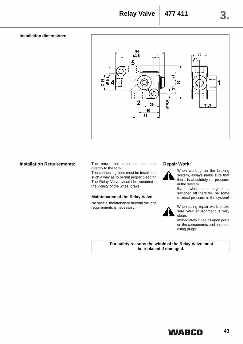
Relay Valve477 4113.Purpose:The purpose of the Relay Valve is torapidly transfer large volumes to thewheel brake. It offers the benefit of beingable to operate with a small actuatingvolume.
Operation:Ready PositionWhen the braking system is ready foroperation, the accumulator pressure ispresent at Port 1 of the Relay Valve. Aconnection is established between Ports2 and 5 so that the wheel brake cylindersof the vehicle are released.
Braking positionWhen the foot brake valve is actuated, ahydraulic braking pressure builds up atPort 2 as a function of the input pressureat Port 4. When the braking process is
commenced, Slide (A) is actuated viaControl Port 4 and moves into the brakingposition against the force of Spring (B).The slide will first close Return Port 5 viathe control edge and then, via anothercontrol edge, connect Accumulator Port1 with Port 2. Via a hole, the oil streamnow flows from Port 1 to Port 2 throughHollow Slide (A), moving it to its finalbraking position. In this process, theoutput braking pressure at Port 2 is equalto the control pressure of the foot brakevalve at Port 4.
Release positionAs the control pressure at Port 4 isreduced, Hollow Slide (A) returns to itsinitial position. The connection betweenPorts 1 and 2 is closed once again by thecontrol edges. The second control edgewill then open the connection betweenPort 1 and Return Port 5.
Technical Data:Part Number 477 411 000 0
Operating pressure 250 bar max.
Control volume 1.3 cm³
Pressure at port 5 < 3 bar
Permissible medium mineral oil: 2000 to 10 mm² /s
Operating temperature range –40°C to +80°C
Transmission ratio 1 : 1
43
Installation dimensions:
Relay Valve 477 411 3.
Installation Requirements: The return line must be connecteddirectly to the tank. The connecting lines must be installed insuch a way as to permit proper bleeding.The Relay Valve should be mounted inthe vicinity of the wheel brake.
Maintenance of the Relay ValveNo special maintenance beyond the legalrequirements is necessary.
Repair Work:When working on the brakingsystem, always make sure thatthere is absolutely no pressurein the system. Even when the engine isswitched off there will be someresidual pressure in the system!
When doing repair work, makesure your environment is veryclean. Immediately close all open portson the components and on pipesusing plugs!
For safety reasons the whole of the Relay Valve must be replaced if damaged.
47
a) All pipes in the braking system musthave a nominal width of at least10 mm.
b) The pipes should be installed in sucha way as to permit proper bleeding,i.e. so that no air cushions candevelop. If you detect noises whencommencing the braking process,this is an indication of poor bleeding.
c) When fitting the pipes, make sure thatthere are no areas of friction.
d) The return lines of the individualcomponents of the braking systemmust not be combined in one returnline to the tank.
e) Do not use a pipe for the return linesof the dual circuit brake valve tocombine them in one return line. (Thisis possible only if Ports 5.1 and 5.2are connected by means of hosesand combined to form one returnline.)
f) Look for visible leaks in lines andpipes. Leaks are an indication thatthe system is not properly sealed.Check the level of the brake fluid.Stop leakage.
g) When using high-pressure cleaners,do not aim the nozzle directly at thebellows. (This may cause damage tothe bellows.)
h) When working on the braking system,always make the sure that the system is completely pressureless!
i) Make sure that everything isspotlessly clean!
j) Immediately close all open ports onthe components and on pipes usingplug!
General Comments
Information for Installation 4.
IMPORTANT !
Even when the engine is switched off or thepump is not running, the system pressure
will be maintained!
48
Information for Installation4.It is particularly important that thecomponents all have their separatereturn lines since otherwise the returnpressure can be present in the wheelbrake in the form of residual pressure.This leads to unnecessary wear of thebrake linings and excessivetemperatures at the wheel brake and canthus result in hardening of the linings,and in a failure of the seals on the wheelbrake cylinders.
When combining the returns of the dualcircuit foot brake valve, please makesure that hoses are used for connectingthe return ports. Using a pipe to connectthe two circuits can cause functionaldefects through distortions in installation.
For very long vehicles with large cylindervolumes, the installation of relay valvescan be very helpful, reducing responseand pressure build-up times to aminimum. The relay valve should befitted as close to the wheel brakecylinders as possible. Thus the lengths ofthe lines from the accumulator to the
wheel brake cylinders are reduced sincethe foot brake valve only actuates therelay valves. The input volume of therelay valves is approx. 1 cm³.
If shut-off valves with an integrated checkvalve are used, an additionalaccumulator of 0.7 litres needs to bescrewed into the component. Thatadditional accumulator is primarily usedto monitor the actual pressure of theother three accumulators and to reportthem to the shut-off valve. Theaccumulators can be emptied when thebrakes are operated, without being re-charged since all circuits are securedfrom each other by the check valves. Theadditional accumulator will also preventactivation of the shut-off valve as aconsequence of small leakages and thusa fall in pressure in the connectionestablished between the check valveseven though the pressure in theaccumulators of the braking circuit is stillhigher than 120 bar.
Information for Installation
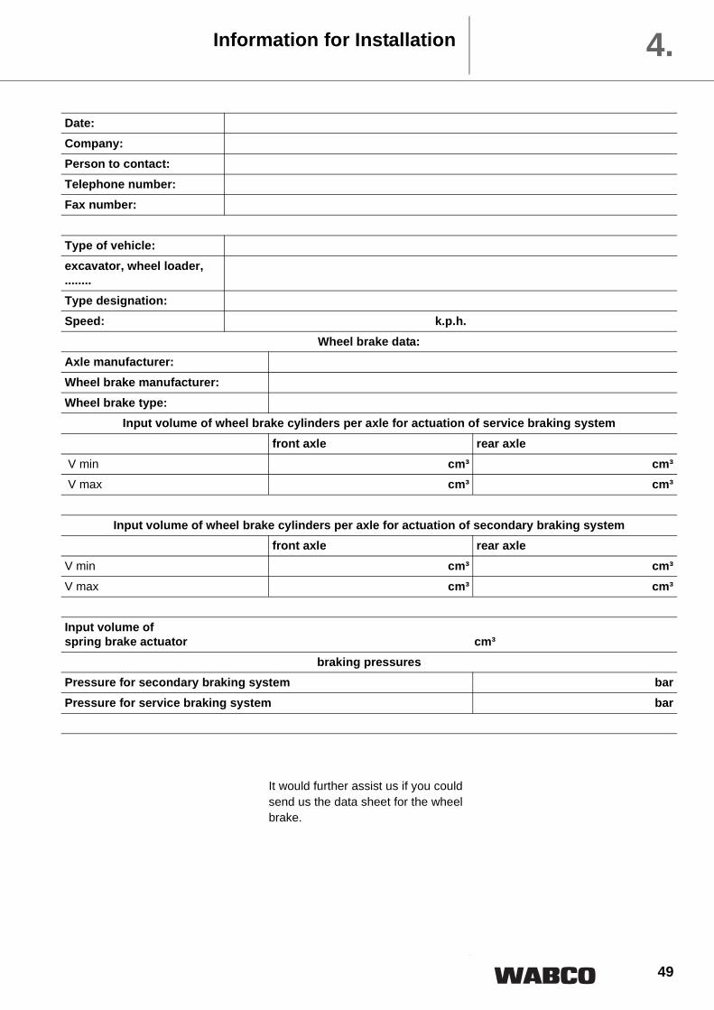
Capacity of Accumulators The capacity of the hydraulicaccumulators must be designedaccording to the legal provisions for theHPB with regard to the size of energyaccumulators.
We support our customers, free ofcharge, in designing the accumulators.
For this purpose we require the followinginformation from you:
49
It would further assist us if you couldsend us the data sheet for the wheelbrake.
Information for Installation 4.
Date:Company:Person to contact:Telephone number:Fax number:
Type of vehicle:excavator, wheel loader,........Type designation:Speed: k.p.h.
Input volume of wheel brake cylinders per axle for actuation of service braking systemfront axle rear axle
V min cm³ cm³ V max cm³ cm³
Input volume of wheel brake cylinders per axle for actuation of secondary braking systemfront axle rear axle
V min cm³ cm³V max cm³ cm³
Input volume of spring brake actuator cm³
braking pressuresPressure for secondary braking system barPressure for service braking system bar
50
Legal Requirements5.C HYDRAULIC BRAKING SYSTEMS WITH STORED ENERGY
1. CAPACITY OF ENERGY STORAGE DEVICES (ENERGY ACCUMULATORS).
1.1. General
1.1.1. Vehicles on which operation of the braking system requires the use ofstored energy provided by hydraulic fluid under pressure shall be equippedwith energy storage devices (energy accumulators) of a capacity meetingthe requirements of paragraph 1.2. of this annex (Part C).
1.1.2. However, the energy storage devices shall not be required to be of aprescribed capacity if the braking system is such that in the absence of anyenergy reserve it is possible with the service braking system control toachieve a braking performance at least equal to that prescribed for thesecondary braking system.
1.1.3. In verifying compliance with the requirements of paragraphs 1.2.1., 1.2.2.and 2.1. of this annex, the brakes shall be adjusted as closely as possibleand, for paragraph 1.2.1., the rate of full-stroke actuations must be such asto provide an interval of at least 60 seconds between each actuation.
1.2. Power-Driven Vehicles
1.2.1. Power-driven vehicles equipped with a hydraulic braking system withstored energy shall meet the following requirements:
1.2.1.1. After eight full-stroke actuations of the service braking system control, itshall still be possible to achieve, on the ninth application, the performanceprescribed for the secondary braking system.
1.2.1.2. Testing shall be performed in conformity with the following requirements:
1.2.1.2.1. Testing shall commence at a pressure that may be specified by themanufacturer but is not higher than the cut-in pressure.
1.2.1.2.2. The energy storage device(s) shall not be fed; in addition, any energystorage device(s) for auxiliary equipment shall be isolated.
1.2.2. Power-driven vehicles equipped with a hydraulic braking system withstored energy which cannot meet the requirements of paragraph 5.2.1.5.1.of this Regulation shall be deemed to satisfy that paragraph if the followingrequirements are met:
1.2.2.1. After any single transmission failure it shall still be possible after eight full-stroke actuations of the service braking system control, to achieve, at theninth application, at least the performance prescribed for the secondarybraking system or, where secondary performance requiring the use ofstored energy is achieved by a separate control, it shall still be possibleafter eight full-stroke actuations to achieve, at the ninth application, theresidual performance prescribed in paragraph 5.2.1.4. of this Regulation.
1.2.2.2. Testing shall be performed in conformity with the following requirements:
1.2.2.2.1. With the energy source stationary or operating at a speed corresponding tothe engine idling speed, any transmission failure may be induced. Beforeinducing such a failure, the energy storage device(s) shall be at a pressurethat may be specified by the manufacturer but not exceeding the cut-inpressure.
ECE Regulation 13 - Annex 7C -
51
1.2.2.2.2. The auxiliary equipment and its energy storage devices, if any, shall beisolated.
2. CAPACITY OF HYDRAULlC FLUID ENERGY SOURCES
2.1. The energy sources shall meet the requirements set out in the followingparagraphs:
2.1.1. Definitions
2.1.1.1. ”p1“ represents the maximum system operational pressure (cut-outpressure) in the energy storage device(s) specified by the manufacturer.
2.1.1.2. ”p2“ represents the pressure after four full-stroke actuations with the servicebrake control, starting at „p1“ without having fed the energy storagedevice(s).
2.1.1.3. ”t“ represents the time required for the pressure to rise from p2 to p1 in theenergy storage device(s) without application of the service braking systemcontrol.
2.1.2. Conditions of Measurement
2.1.2.1. During the test to determine the time t, the feed rate of the energy sourceshall be that obtained when the engine is running at the speedcorresponding to its maximum power or at the speed allowed by the over-speed governor.
2.1.2.2. During the test to determine the time t, energy storage device(s) forauxiliary equipment shall not be isolated other than automatically.
2.1.3. Interpretation of Results
2.1.3.1. In the case of all vehicles except those of categories M3, N2 and N3 the timet shall not exceed 20 seconds.
2.1.3.2. In the case of vehicles of categories M3, N2 and N3 the time t shall notexceed 30 seconds.
3. CHARACTERISTICS OF WARNING DEVICES
With the engine stationary and commencing at a pressure that may bespecified by the manufacturer but does not exceed the cut-in pressure, thewarning device shall not operate following two full-stroke actuations of theservice braking system control.