Comtech EFData, 2114 West 7th Street, Tempe, Arizona 85281 USA, (480) 333-2200, FAX: (480) 333-2161.
EFData Corporation is an ISO 9001 Registered Company
HPCST-5000HPCST-5000HPCST-5000HPCST-500075W, 100W, 125W, and 150W SSPA System75W, 100W, 125W, and 150W SSPA System75W, 100W, 125W, and 150W SSPA System75W, 100W, 125W, and 150W SSPA SystemHigh-Power C-Band Satellite TerminalHigh-Power C-Band Satellite TerminalHigh-Power C-Band Satellite TerminalHigh-Power C-Band Satellite TerminalInstallation and Operation ManualInstallation and Operation ManualInstallation and Operation ManualInstallation and Operation Manual
Part Number MN/HPCST5000.IOMRevision 0October 19, 1998
Warranty Policy
This EFData Corporation product is warranted against defects in material andworkmanship for a period of one year from the date of shipment. During the warrantyperiod, EFData will, at its option, repair or replace products that prove to be defective.
For equipment under warranty, the customer is responsible for freight to EFData andall related custom, taxes, tariffs, insurance, etc. EFData is responsible for the freightcharges only for return of the equipment from the factory to the customer. EFData willreturn the equipment by the same method (i.e., Air, Express, Surface) as theequipment was sent to EFData.
Limitations of Warranty
The foregoing warranty shall not apply to defects resulting from improper installationor maintenance, abuse, unauthorized modification, or operation outside ofenvironmental specifications for the product, or, for damages that occur due toimproper repackaging of equipment for return to EFData.
No other warranty is expressed or implied. EFData Corporation specificallydisclaims the implied warranties of merchantability and fitness for particularpurpose.
Exclusive Remedies
The remedies provided herein are the buyer's sole and exclusive remedies. EFDataCorporation shall not be liable for any direct, indirect, special, incidental, orconsequential damages, whether based on contract, tort, or any other legal theory.
Disclaimer
EFData has reviewed this manual thoroughly in order that it will be an easy-to-useguide to your equipment. All statements, technical information, and recommendationsin this manual and in any guides or related documents are believed reliable, but theaccuracy and completeness thereof are not guaranteed or warranted, and they arenot intended to be, nor should they be understood to be, representations or warrantiesconcerning the products described. Further, EFData reserves the right to makechanges in the specifications of the products described in this manual at any timewithout notice and without obligation to notify any person of such changes.
If you have any questions regarding your equipment or the information in this manual,please contact the EFData Customer Support Department. (For more information,refer to the preface.)
Rev. 0 i
Preface
About this Manual
This manual provides installation and operation information for the EFDataHPCST-5000 high-power C-Band satellite terminal. This is a technical documentintended for earth station engineers, technicians, and operators responsible for theoperation and maintenance of the HPCST-5000.
Conventions and References Used in this Manual
Cautions and Warnings
CAUTION
CAUTION indicates a hazardous situation that, if not avoided, may result inminor or moderate injury. CAUTION may also be used to indicate otherunsafe practices or risks of property damage.
WARNING
WARNING indicates a potentially hazardous situation that, if not avoided,could result in death or serious injury.
Trademarks
Product names mentioned in this manual may be trademarks or registered trademarks oftheir respective companies and are hereby acknowledged.
Preface High-Power C-Band Satellite Terminal
ii Rev. 0
Related Documents
The following documents are referenced in this manual:
! EFData CST-5000 C-Band Satellite Terminal Installation and OperationManual
! EFData RSU-503L Redundancy Switch Unit Installation and Operation Manual ! EFData KP-10 External Keypad Installation and Operation Manual ! EFData Monitor and Control Software for EFData Satellite Terminals User’s
Guide
! EFData Specification SP/6750, HPCST-5000 High Power C-Band SatelliteSystem
! EFData Specification SP/5351, HPA-6075 C-Band and 75W Power Amplifier ! EFData Specification SP/5110, HPA-500/-700 C-Band High Power (TWT)
Amplifier
! EFData Specification SP/5389, HPCST-5000 High Power C-Band SatelliteTerminal System
Reporting Comments or Suggestions Concerning this Manual
Comments and suggestions regarding the content and design of this manual will beappreciated. To submit comments, please contact the EFData Customer SupportDepartment according to the following information.
High-Power C-Band Satellite Terminal Preface
Rev. 0 iii
Customer Support
Contact the EFData Customer Support Department for:
! Product support! Information on returning a product! Information on upgrading a product! Product training! Reporting comments or suggestions concerning manuals
An EFData Customer Support representative may be reached at:
EFData CorporationAttention: Customer Support Department2114 West 7th StreetTempe, Arizona 85281 USA
1-7 HPCST-5000 Specifications .................................................................................................................... 1–151.7.1 Prime Power Specification ................................................................................................................ 1–151.7.2 System Interface ................................................................................................................................ 1–151.7.3 System Environment Specification.................................................................................................... 1–161.7.4 HPCST-5000 Monitor and Control ................................................................................................... 1–171.7.5 System Receive Specification ........................................................................................................... 1–181.7.6 System Transmit Characteristics ....................................................................................................... 1–191.7.7 Leading Particulars............................................................................................................................ 1–20
Table of Contents High-Power C-Band Satellite Terminal
3.2 Inspecting the Equipment.......................................................................................................................... 3–43.2.1 Included Parts...................................................................................................................................... 3–4
4.2 Inspecting the Equipment.......................................................................................................................... 4–44.2.1 Included Parts...................................................................................................................................... 4–4
5.1 System Operation....................................................................................................................................... 5–1
5.2 Remote Control .......................................................................................................................................... 5–1
5.3 Front Panel Display/Keypad..................................................................................................................... 5–25.3.1 Front Panel Controls............................................................................................................................ 5–3
5.4 Main Menu ................................................................................................................................................. 5–45.4.1 Configuration ...................................................................................................................................... 5–55.4.2 Monitor................................................................................................................................................ 5–95.4.3 Faults ................................................................................................................................................. 5–11
CHAPTER 6. THEORY OF OPERATION .................................................................6–1
6.1 Monitor and Control ................................................................................................................................. 6–16.1.1 EEPROM Memory.............................................................................................................................. 6–36.1.2 Remote Interface ................................................................................................................................. 6–3
6.1.2.1 Remote Interface Specification................................................................................................... 6–46.1.3 Terminal Default Conditions............................................................................................................... 6–46.1.4 Theory of Operation............................................................................................................................ 6–46.1.5 M&C Board Connector Pinouts .......................................................................................................... 6–6
6.1.6 Test Points and LEDs........................................................................................................................ 6–10
6.2 High Stability Oscillator.......................................................................................................................... 6–10
Table of Contents High-Power C-Band Satellite Terminal
6.3 IF Local Oscillator ................................................................................................................................... 6–126.3.1 Specifications .................................................................................................................................... 6–12
6.4 Synthesizer................................................................................................................................................ 6–146.4.1 Specifications .................................................................................................................................... 6–146.4.2 Theory of Operation.......................................................................................................................... 6–14
6.5 Down Converter....................................................................................................................................... 6–166.5.1 Specifications .................................................................................................................................... 6–176.5.2 Theory of Operation.......................................................................................................................... 6–18
6.6 Up Converter............................................................................................................................................ 6–196.6.1 Specifications .................................................................................................................................... 6–206.6.2 Theory of Operation.......................................................................................................................... 6–21
7.1 Test Points and LEDs ................................................................................................................................ 7–1
CHAPTER 8. EQUIPMENT LIST ...............................................................................8–1
8.1 Equipment List ........................................................................................................................................... 8–1
A.1.2.1 Specifications .............................................................................................................................A–3A.1.2.2 Theory of Operation ...................................................................................................................A–3
A.1.3 Down Converter ..................................................................................................................................A–5A.1.3.1 Specifications .............................................................................................................................A–5A.1.3.2 Theory of Operation ...................................................................................................................A–7
A.1.4 Up Converter.......................................................................................................................................A–8A.1.4.1 Specifications .............................................................................................................................A–8A.1.4.2 Theory of Operation .................................................................................................................A–10
APPENDIX B. REMOTE CONTROL OPERATION................................................... B–1
High-Power C-Band Satellite Terminal Table of Contents
Rev. 0 ix
B.1 General ...................................................................................................................................................B–1
Low Noise Amplifier (LNA) 65! KLNA with TRF (Optional: Noise Temperatures available)Radio Frequency Transceiver (RFT) Consists of an:
" Up converter with 70 (140) MHz IF input" Down converter with a 70 (140) MHz IF output" M&C microprocessor" Power supply
Solid-State Power Amplifier (SSPA) Consists of a solid-state power amplifier.Redundancy Configuration
1:1 Redundant LNA Plate Consists of transmit reject filter, redundant LNAs (65!K), and a C-Band waveguide switch.
Radio Frequency Terminal (RFT) Consists of two radio frequency terminal (RFT) assemblies.C-Band SSPA Assembly Consists of two solid-state power amplifiers.Redundancy Switch Unit (RSU-503L) Along with a redundancy cable/hardware kit, the RSU-503L
provides the system with a single M&C interface, redundancyswitchover control, and cabling.
The HPCST-5000 outdoor terminal consists of weatherproof components for uplink anddownlink requirements. The redundant assemblies have been designed for antenna or polemounting. The system has a single user interface connector for remote M&C.
In the TX (uplink) direction, the terminal accepts a 70 (140) MHZ IF signal and TX it inthe 5.850 to 6.425 GHz frequency band. This output is coupled through an N-typeconnector to the external high power amplifier (SSPA) assembly.
In the redundant system, a high power output to the antenna through a waveguide transferswitch is provided. A high-power termination is included on the offline channel port ofthe waveguide switch for testing.
In the RX (downlink) direction, the terminal accepts an RF signal in the 3.6 to 4.2 GHzband, and converts the signal to a 70 (140) MHz IF output. The LNA assembly has atype-N coax output routed to RFT RX RF inputs. The RFT TX output power level at 1 dBcompression used to drive the external SSPA is +8 dBm maximum. The up and downconverters are dual conversion, configured with a single or dual synthesizer for TX andRX transponder selection.
The onboard microcomputer monitors and controls (M&C) the operational parameters ofthe HPCST-5000 components. The M&C system enables the user to locally or remotelycontrol functions such as:
" Output power level " TX/RX channel frequency" Output On/Off
High Power C-Band Satellite Terminal Introduction
Rev. 0 1–3
The system also reports terminal configuration status, as well as fault status of allHPCST-5000 components.
The RFT terminal can be initially configured by a keyboard/LCD controller within theenclosure, or by connection of a common ASCII/EIA-232 terminal connected to the serialport at the redundancy system interface connector (RSU [J16]). A command set to allowconfiguration control and retrieval of status information. If the customer M&C controlunit is a sophisticated M&C station computer; the serial port can be set to EIA-485 forbus operation.
1.2 Applications
When used in conjunction with EFData modems, the HPCST-5000 is ideal for:
" Single digit carriers up to 2.048 Mbit/s.
" Multiple carrier operation over a 36/72 MHz bandwidth.
Note: Refer to Appendix A for the 140 MHz configuration.
Because the HPCST-5000 has a 70 MHz IF input, it can also be used for other analog anddigital applications.
Small-to-medium size earth stations are easily constructed and commissioned with theHPCST-5000.
When used with a high-gain antenna, the HPCST-5000 can also be used as the RadioFrequency (RF) electronics of a central hub in point-to-multipoint applications, as well asserve as the terminal for the end points of a network.
Introduction High-Power C-Band Satellite Terminal
1–4 Rev. 0
1.3 Options
Refer to Table 1-2 for HPCST-5000 options.
Table 1-2. HPCST-5000 Options
Wattage, W Cable/Hardware Kit (Output) CrossguideCoupler
75 Standard Duplex None100 Standard TX Only 40 dB125150
Refer to Figure 1-2 for configuration options.
High Power C-Band Satellite Terminal Introduction
Rev. 0 1–5
SINGLE THREADOR
REDUNDANT SYSTEM
Single Threador
Redundant System
Select TwoRFT-500 Select One
RFT-500
Select OneRSU-503L
Select OneCLNASelect One
Redundant LNAPlate
Select Cable KitSelect TwoCLNA
SelectMounting Kit
Select Cable Kit
SelectMounting Kit
Redundant System Single Thread
KP-10 Hand-HeldKeypad
(Optional)
KP-10 Hand-HeldKeypad
(Optional)
Select OneSSPA
Select TwoSSPA
Figure 1-2. Configuration Options
Introduction High-Power C-Band Satellite Terminal
1–6 Rev. 0
1.4 Configurations
The HPCST-5000 can be ordered with various configurations, including:
" Single Thread Configuration" 1:1 Redundant Configuration
1.4.1 Single Thread Configuration
Note: Refer to Section 3 for a detailed description of the single thread configuration.
The HPCST-5000 outdoor terminal consists of weatherproof components for uplink anddownlink requirements. The single thread configuration (Figure 1-3) has been designedfor antenna or pole mounting. The HPCST-5000 has a single customer-interfaceconnector for remote monitor and control.
The on-board microcomputer monitors and controls the operational parameters. ThisMonitor and Control (M&C) system enables the customer to locally or remotely controlfunctions such as:
" Input/Output attenuator level" TX Output On/Off" TX/RX channel frequency
The HPCST-5000 reports terminal configuration status, as well as fault status of allcomponents. The RFT-500 can be initially configured by an optional on-board keypad, oran optional KP-10 Hand-Held Keypad, or by a connection of a common ASCII/EIA-232or EIA-485 terminal connected to the serial port at the system interface connector (P1). Asimple command set allows configuration control and retrieval of status information.
Refer to the KP-10 Hand-Held Keypad, Installation and Operation Manual.
High Power C-Band Satellite Terminal Introduction
Rev. 0 1–7
A
LNALOCATION
EARTHSTATION
C-BANDSSPA
RFT-500
CONNECTOR(J6)
CONNECTOR(J6)
SIDEVIEW
FRONTVIEW
DETAIL A
Figure 1-3. Typical View of Single Thread Installations
Introduction High-Power C-Band Satellite Terminal
1–8 Rev. 0
1.4.2 Redundant System
Note: Refer to Section 4 for a detailed description of the redundancy configuration.
Refer to Table 1-3 for typical HPCST-5000 redundant system components.
(65!K), and a C-Band waveguide switch.Radio Frequency Terminal (RFT) Consists of two radio frequency terminal (RFT)
assemblies. Each RFT includes an up converter, adown converter, an M&C microprocessor, and apower supply.
C-Band SSPA Assembly Consists of two high-power SSPAs and a waveguideswitch, high-power termination and connectingwaveguide.
Redundancy Switch Unit (RSU-503L) Along with a redundancy cable/hardware kit, the RSU-503L provides the system with a single M&Cinterface, redundancy switchover control, and cabling.
Note: For more information, refer to RSU-503 Redundancy Switch Unit Installation andOperation Manual.
The HPCST-5000 system outdoor terminal components are weatherproof units for theuplink and downlink requirements. The redundant assemblies have been designed forantenna or pole mounting. The HPCST-5000 system has a single customer-interfaceconnector for remote monitor and control.
The on-board microcomputer monitors and controls the operational parameters. ThisM&C system enables the user to locally or remotely control functions such as:
" Input/Output attenuator level" Output On/Off" Transmit/Receive channel frequency
The HPCST-5000 reports terminal configuration status, as well as fault status of allcomponents. The RFT can be initially configured by an optional on-board keypad or anoptional KP-10 Hand-held Keypad, or by connection of a common ASCII/EIA-232 orEIA-485 terminal connected to the serial port at the system interface connector. A simplecommand set allows configuration control and retrieval of status information.
High Power C-Band Satellite Terminal Introduction
Rev. 0 1–9
1.5 Component Descriptions
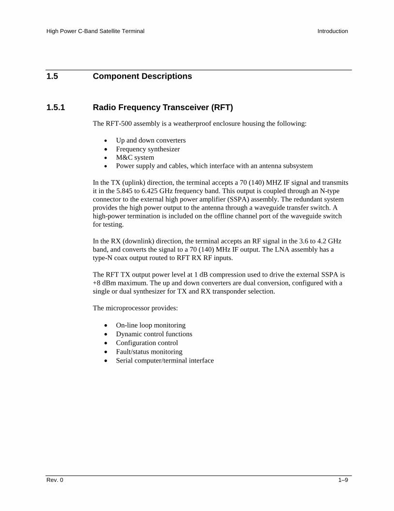
1.5.1 Radio Frequency Transceiver (RFT)
The RFT-500 assembly is a weatherproof enclosure housing the following:
" Up and down converters" Frequency synthesizer" M&C system" Power supply and cables, which interface with an antenna subsystem
In the TX (uplink) direction, the terminal accepts a 70 (140) MHZ IF signal and transmitsit in the 5.845 to 6.425 GHz frequency band. This output is coupled through an N-typeconnector to the external high power amplifier (SSPA) assembly. The redundant systemprovides the high power output to the antenna through a waveguide transfer switch. Ahigh-power termination is included on the offline channel port of the waveguide switchfor testing.
In the RX (downlink) direction, the terminal accepts an RF signal in the 3.6 to 4.2 GHzband, and converts the signal to a 70 (140) MHz IF output. The LNA assembly has atype-N coax output routed to RFT RX RF inputs.
The RFT TX output power level at 1 dB compression used to drive the external SSPA is+8 dBm maximum. The up and down converters are dual conversion, configured with asingle or dual synthesizer for TX and RX transponder selection.
The microprocessor provides:
" On-line loop monitoring" Dynamic control functions" Configuration control" Fault/status monitoring" Serial computer/terminal interface
Introduction High-Power C-Band Satellite Terminal
1–10 Rev. 0
1.5.2 Low Noise Amplifier (LNA)
The low noise amplifier (LNA) assembly consists of a TX reject filter, waveguide switch,and two 65!K low-noise 50 dB gain amplifiers.
1.5.3 Solid-State Power Amplifier (SSPA)
Note: Refer to the SSPA Installation and Operational Manual for additional data.
The SSPA is available in:
" 75W" 100W" 125W" 150W
The SSPA consists of the following subassemblies:
" Power amplifier" Output waveguide assembly" RF input isolation circuit
The SSPA is forced air cooled by a fan controlled by a thermal switch. The cooling fan isconfigured for 48 VDC operation. Depending upon the environmental conditions, the heatsink fins may become obstructed by debris, reducing the efficiency of the cooling system.The heat sink fins may require periodic maintenance in the form of removing debris.
1.5.4 Monitor and Control (M&C)
An on-board microcomputer monitors and controls all operational parameters and systemstatus of the HPCST-5000. This powerful M&C system enables the user to locally orremotely control functions such as:
The 1:1 redundant LNA plate provides noise temperature equivalent of 65!K and consistsof two LNAs, waveguide switch (see Figure 1-4), and transmit reject filter.
Figure 1-4. 1:1 Redundant LNA Plate
Note: Other LNAs are available. Contact EFData Customer Support for moreinformation.
Introduction High-Power C-Band Satellite Terminal
1–12 Rev. 0
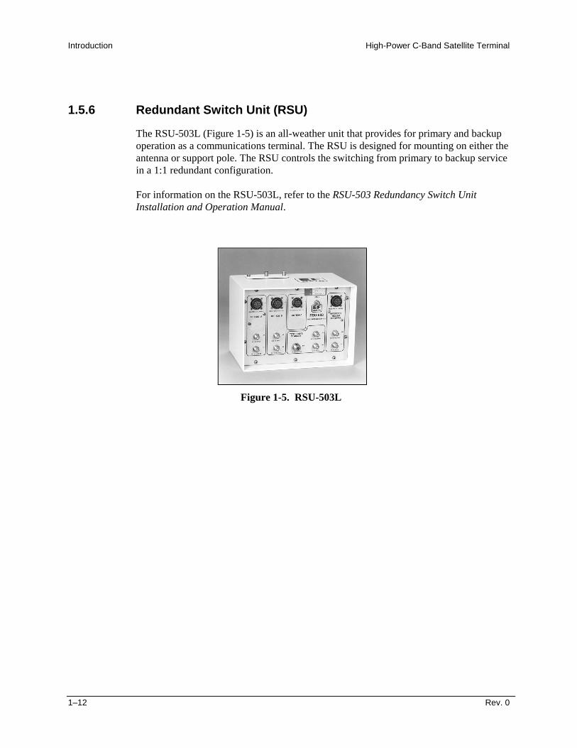
1.5.6 Redundant Switch Unit (RSU)
The RSU-503L (Figure 1-5) is an all-weather unit that provides for primary and backupoperation as a communications terminal. The RSU is designed for mounting on either theantenna or support pole. The RSU controls the switching from primary to backup servicein a 1:1 redundant configuration.
For information on the RSU-503L, refer to the RSU-503 Redundancy Switch UnitInstallation and Operation Manual.
Figure 1-5. RSU-503L
High Power C-Band Satellite Terminal Introduction
Rev. 0 1–13
1.5.7 KP-10 Hand-Held Keypad (Optional)
The optional KP-10 (Figure 1-6) is a handheld keypad that provides portable, externalaccess for controlling Radio Frequency Terminals (RFTs) which are components of aCST, HPCST, or KST satellite terminal.
The KP-10 is typically used for initial set up or occasional changes to the configurationsof RFTs, in both single and redundant systems. When the KP-10 is used with a redundantsystem, it is connected to an EFData redundancy switch unit.
Refer to the KP-10 Hand-Held Keypad, Installation and Operation Manual.
Figure 1-6. KP-10 Hand-Held Keypad (Optional)
Introduction High-Power C-Band Satellite Terminal
1–14 Rev. 0
1.6 High-Power C-Band Satellite Terminal Models
The HPCST is specifically designed for outdoor installation for earth station satellitecommunication. Because of the design, the units can be mounted on the antenna or thepole reducing transmission losses to the antenna feed. Refer to Table 1-4 for the HPCSTmodel configurations.
Table 1-4. HPCST Models
Band Model # FrequencyRated TX/RF
Power, W
C-Band HPCST-5000 TX: 5.845 to 6.425 GHz 75100125150
C-Band HPCST-5000 RX: 3.620 to 4.200 GHz N/A
High Power C-Band Satellite Terminal Introduction
Rev. 0 1–15
1.7 HPCST-5000 Specifications
1.7.1 Prime Power Specification
Refer to Table 1-5 for prime power specifications.
Table 1-5. Prime Power Specifications
Assembly Ref Des Option Prime Power/Power ConsumptionRFT-500 J5 AC 90 to 265 VAC, 47 to 63 Hz, 90WSSPA-500:
75W100W125W150W
J5J5J5J5
ACACACAC
Prime Power/Power Consumption90 to 265 VAC, 47 to 63 Hz, 500W90 to 265 VAC, 47 to 63 Hz, 700W90 to 265 VAC, 47 to 63 Hz, 800W90 to 265 VAC, 47 to 63 Hz, 1000W
LNA DC 10.8 # 0.2 VDC (as provided from RSU)RSU-503L J4, J8 DC 10.8 VDC (from either RFT-500)
1.7.2 System Interfaces
Refer to Table 1-6 for system interfaces on units.
Table 1-6. System Interfaces on Units
Description TypeRFT-500:
TX IF Input (J1)RX IF Output (J3)RX RF Input (J4, C-Band)TX RF Output (J2, C-Band)M&C Control (J6)
M&C Single Thread System with SSPA Circular, KPT06E-16-26P on RFT-500M&C 1:1 System with SSPA Use J16 on RSU-503LWaveguide TX Switch with SSPA Circular, MS3112E-14-6S
1.7.3 System Environment Specification
Refer to Table 1-7 for environmental conditions.
Table 1-7. Environmental Specifications
Environment ConditionsTemperature:
OperatingSurvival
-40! to +50!C (-40! to 122!F)-50! to +70!C (-58! to 158!F) , non-operating
Vibration 1.5g, 5 to 200 Hz and normal transportation levelsShock 6g maximumHumidity 0% to 100% relative at -40! to +50!C (-40! to 122!F)
95% at 55!C (131!F ) for 72 hoursPrecipitation MIL-STD-810/Method 506.2Salt Fog MIL-STD-810/Method 509.2Sand and Dust MIL-STD-810/Method 510.1Altitude:
OperationSurvival
0 to 10,000 ft, derate 2!C/1000 ft ASL0 to 40,000 ft
Solar Radiation 360 BTU/hr/ft2 at 50!C (122!F)Safety EN60950 (IEC-950, UL 1950)Emissions EN55022, Class A (FCC Part 15J, Class A)Immunity EN50082-1
High Power C-Band Satellite Terminal Introduction
Rev. 0 1–17
1.7.4 HPCST-5000 Monitor and Control
The HPCST-5000 terminal system has a single interface connector (J16) located on theRSU-503L for redundant configurations. For single thread configuration, the M&C isconnected to connector (P1) on the RFT-500. The interface provides the customer withcontrol of the terminal system redundant configuration including the C-Band SSPAthrough the integrated system cable harness. The options for customer control of theterminal system are provided in Table 1-8.
Table 1-8. System Monitor and Control
System Type Interface M&C OptionsHPCST-5000 TerminalSystem
EIA-232/EIA-485 Serial Bus On-board Keypad, KP-10 HandheldKeypad, or ASCII terminal through J16of the RSU-503L.
Introduction High-Power C-Band Satellite Terminal
1–18 Rev. 0
1.7.5 System Receive Characteristics
The RX performance is defined for the C-Band LNA input to the 70 (140) MHz output ofthe RFT-500. Intervening cable losses due to installation variables must be accounted forwhen comparing to the performance data provided in Table 1-9.
Table 1-9. System Receive Characteristics
Receiver CharacteristicsInput Frequency Range 3.625 to 4.200 GHz in 2.5 MHz steps
(Optional: 125 kHz)Frequency Sense No inversionInput Level -127 to -80 dBmRX GainAdjust (0.05 dB typical steps, 1 dB maximum)
95 dB minimum0 to 20 dB minimum (remotely controlled)
RX Frequency Stability # 1 x 10⁻⁸ at 23!C (73!F)Life RX Frequency Stability # 1 x 10⁻⁷ at 23!C (73!F)Gain Flatness # 1.0 dB/36 MHz
# 0.25 dB/4 MHzRX IF Output Bandwidth 70 # 18 MHz at 1 dB
(Optional: 140 # 36 MHz at 2 dB)Noise Figure 65! K (other options available)TX Frequency Reject 60 dBmRX image Rejection -45 dBmLinearity (Third order intercept) Intermods % -35 dBc for two tones at –89 dBm
Spurious (signal related) at 0 dBm RX IF output -40 dBcInband Overdrive No damage to 0 dBmThird Order Intercept +25 dBm minimumRX IF Output at 1 dB Compression +15 dBm minimum
High Power C-Band Satellite Terminal Introduction
Rev. 0 1–19
1.7.6 System Transmit Characteristics
TX characteristics for the system are provided in Table 1-10.
Note: 1 dB compression characteristic is measured at the output flange of the C-BandSSPA.
Table 1-10. System Transmit Characteristics
Transmit CharacteristicsFrequency Range 5.845 to 6.425 GHz, in 2.5 MHz steps
(125 kHz optional)Small Signal Gain (10 dB backoff), Nominal 75W
79 dB100W80 dB
125W81 dB
150W82 dB
TX IF Input Level Range -35 to -25 dBm typicalPower Output at P1dB: (minimum) 75W
48 dBm100W49 dBm
125W50 dBm
150W51 dBm
TX IF Input Bandwidth at –1 dB 70 # 18 MHz (Optional: 140 # 36 MHz)Gain: Stability (Overtemp)FlatnessVariation
# 1.5 dB# 1.5 dB/36 MHz# 2.0 dB
Group Delay (any 36 MHz):LinearParabolicRipple
% 30 ns0.28 ns/MHz0.15 ns/MHz2
% 1 ns P-PTX Frequency Stability # 1 x 10⁻⁸
TX Synthesizer Lock-up Time % 1 secondSpurious (not inter-mods) :
At 6 dB backoff from P1 dB
With Carrier Off
Intermod Spurious with two equal carriers
Harmonics (out-of-band)
IESS-309, Para. 3.2.1
-40 dBc min. (& 2.048 MHz inform. rate)-50 dBc min. (' 2.048 MHz inform. rate)
The physical size and weight of the terminal system components are provided in Table1-11.
Note: A redundant system is twice the size and weight of the single system.
Table 1-11. Leading Particulars
Component Maximum Size and WeightRFT-500:
Single Thread System:DimensionsWeight
23”L x 9.3” W x 10.3” H (58.42 x 23.62 x 26.16 cm)40 lbs. (18.1 kg)
SSPA-500:Single Thread System:
DimensionsWeight
18.5”L x 9.75”W x 9.25”H (46.99 x 24.76 x 23.49 cm)35 lbs. (18.1 kg)
1:1 SSPA-500:Redundant Configuration:
DimensionsWeight
29.75”L x 21.25”W x 9.25”H (75.56 x 53.97 x 23.49 cm)95 lbs. (43.09 kg)
RSU-503L:DimensionsWeight
8.0”L x 11.0”W x 8.0”H (20.32 x 27.94 x 20.32 cm)7.5 lbs (3.40 kg)
LNA (Dual):DimensionsWeight
26.0”L x 21.0”W x 14”H (66.04 x 53.34 x 35.56 cm)20 lbs (9.07 kg)
High Power C-Band Satellite Terminal Introduction
Rev. 0 1–21
1.8 RFT Specification
Refer to Table 1-12 for RFT-500 specifications.
Table 1-12. RFT-500 Specifications
Transmit CharacteristicsOutput Frequency (No Inversion) 5.845 to 6.425 GHzInput Frequency 70 # 18 MHz
140 # 36 MHz (optional)Output Power at 1 dB compression +8 dBmThird Order Intercept +18 dBm (for +8 dBm)Nominal Small Signal Gain 26 dB (for +8 dBm)Gain Adjust Range 0 to 25 dB, in 0.5 dB stepsGain Variation:
Frequency Stability:Annual at 23!COver TemperatureAfter 30 Minutes Warm-upElectrical Adjustment
# 1 x 10⁻⁷
# 1 x 10⁻⁸ (-40! to +55!C) (-40! to +131!F)# 1 x 10⁻⁸
0.5 x 10⁻⁷
Isolation on Fault Shutdown -60 dBc minimumSpurious:
< 250 kHz Carrier Offset> 250 kHz Carrier Offset
-35 dBc maximum-50 dBc maximum
RF Output VSWR 1.5:1 at 50$RF Output Connector N-Type femaleIF Input VSWR 1.5:1 at 50$IF Input Connector TNC female
Introduction High-Power C-Band Satellite Terminal
1–22 Rev. 0
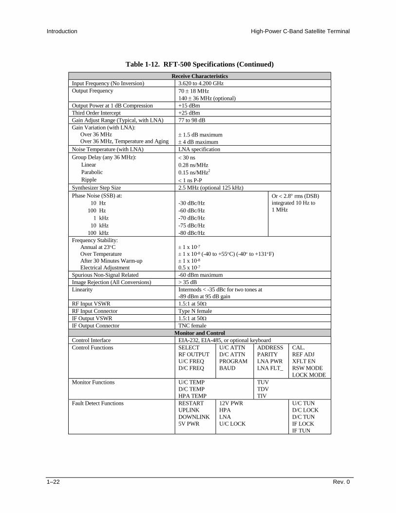
Table 1-12. RFT-500 Specifications (Continued)
Receive CharacteristicsInput Frequency (No Inversion) 3.620 to 4.200 GHzOutput Frequency 70 # 18 MHz
140 # 36 MHz (optional)Output Power at 1 dB Compression +15 dBmThird Order Intercept +25 dBmGain Adjust Range (Typical, with LNA) 77 to 98 dBGain Variation (with LNA):
Over 36 MHzOver 36 MHz, Temperature and Aging
# 1.5 dB maximum# 4 dB maximum
Noise Temperature (with LNA) LNA specificationGroup Delay (any 36 MHz):
Refer to Table 1-13 for C-Band SSPA specifications.
Table 1-13. C-Band SSPA Specifications
Parameter SpecificationPower:
Power RequirementsPower ConsumptionPower Factor Correction
90 to 230 VAC, 47 to 63 Hz, single phase6A typical at 110 VAC95%, minimum
Frequency Range 5.845 to 6.450 GHzPower Output (P1dB) 75 W
48100 W
49125 W
50150 W
51Small Signal Gain 75 W
79100 W
80125 W
81150 W
82Gain Flatness (at room temperature),maximum
2 dB P–P over 600 MHz0.6 dB P–P over 40 MHz
Gain Slope 0.015 dB/MHz, maximumGain Variation # 1.5 dB over frequency and temp rangeLocal Gain Adjustment # 3 dB, minimumInput Return Loss 19 dB, minimumOutput Return Loss 19 dB, minimumNoise Figure at Maximum Gain 10 dBSpurious Rated Power, maximum -65 dBc, maximumHarmonic at rated power -60 dBc, maximumAM/PM Conversion at Rated Power 2.5!/dBThird Order Intermodulation(Two equal tones 5 MHz apart)
-34 dBc at 6 dB backoff from rated P1dB
-26 dBc at 3 dB backoff from rated P1dB
Group Delay:LinearParabolicRipple
0.02 ns/MHz0.003 ns/MHz2
1 ns P–PResidual AM (F* = Frequency in kHz) -45 dBc
-20 (1+ log F*) dBc-80 dBc
0 to 10 kHz10 kHz to 500 kHz500 kHz to 1 MHz
Phase Noise Meets IESS-308/-309
Introduction High-Power C-Band Satellite Terminal
1–24 Rev. 0
1.10 LNA Specification
Refer to Table 1-14 for LNA specification.
Table 1-14. LNA Specifications
Parameter SpecificationFrequency 3.620 to 4.200 GHzNoise Temperature (with TRF) 65!K maximum (lower temperatures optional)Gain 50 dB minimum, 54 dB nominal
(optional 60 dB)Gain Flatness # 1 dB/575 MHzGain vs. Temperature # 3 dB maximum1 dB Compression Point +10 dBm minimumThird Order Intercept +20 dBm minimumGroup Delay:
Input VSWR 1.25:1Output VSWR 1.5:1Input Connector CPR229G (hold pressure to 0.5 PSIG)Output Connector Type NSpurious Below thermal noise/100 kHzTRF Rejection 55 dB
High Power C-Band Satellite Terminal Introduction
Rev. 0 1–25
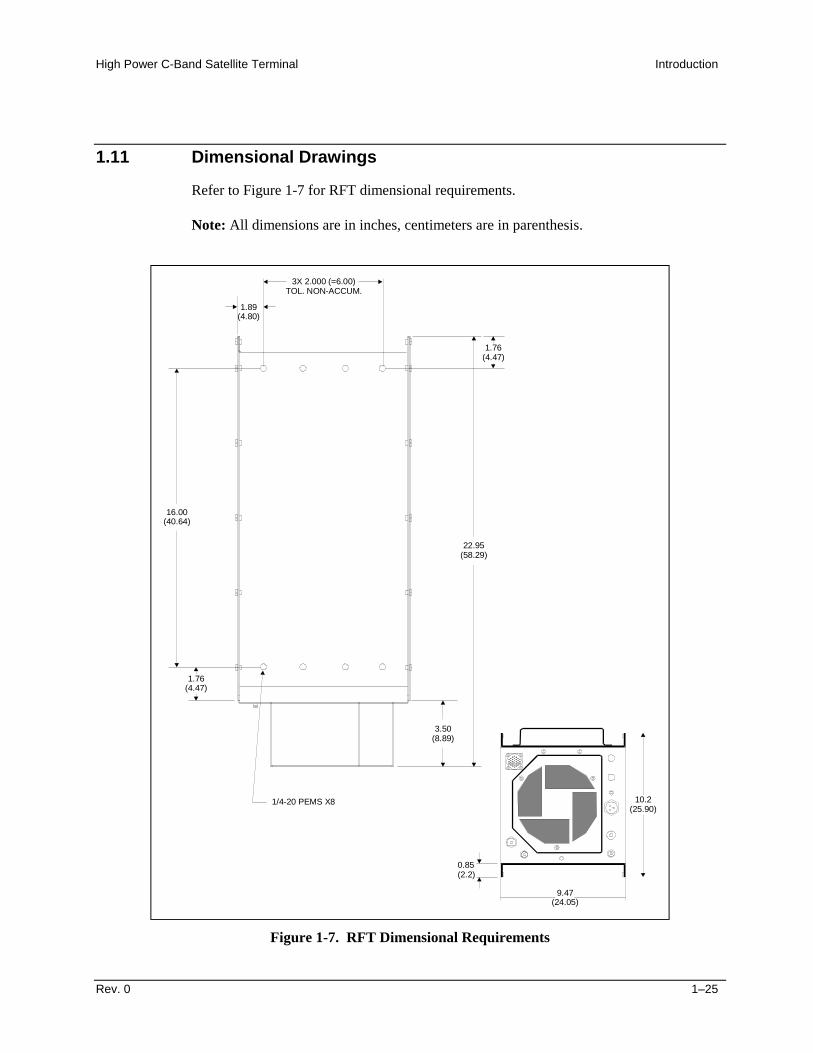
1.11 Dimensional Drawings
Refer to Figure 1-7 for RFT dimensional requirements.
Note: All dimensions are in inches, centimeters are in parenthesis.
1.89(4.80)
3X 2.000 (=6.00)TOL. NON-ACCUM.
16.00(40.64)
1.76(4.47)
1.76(4.47)
3.50(8.89)
22.95(58.29)
1/4-20 PEMS X8 10.2(25.90)
9.47(24.05)
0.85(2.2)
Figure 1-7. RFT Dimensional Requirements
Introduction High-Power C-Band Satellite Terminal
1–26 Rev. 0
Refer to Figure 1-8 for C-Band SSPA dimensional requirements.
Note: All dimensions are in inches, centimeters are in parenthesis.
9.80(24.89)
0.40(6 PLACES)
0
9.07(23.03)
1.47(3.73)
2.54(6.45)
9.09(23.08)
A
DIMENSION A
75W 100W 125W 150W
16.15(40.89)
18.27(46.41)
18.27(46.41)
18.27(46.41)
Figure 1-8. C-Band SSPA Dimensional Requirements
High Power C-Band Satellite Terminal Introduction
Rev. 0 1–27
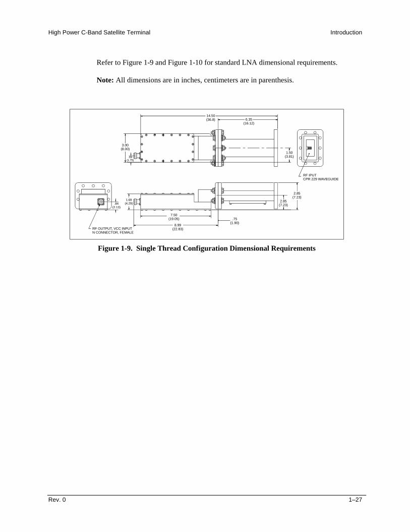
Refer to Figure 1-9 and Figure 1-10 for standard LNA dimensional requirements.
Note: All dimensions are in inches, centimeters are in parenthesis.
14.50(36.8) 6.35
(16.12)
1.50(3.81)
2.85(7.23)
2.85(7.23)
8.99(22.83)
.75(1.90)
7.50(19.05)
RF OUTPUT, VCC INPUTN CONNECTOR, FEMALE
1.69(4.29).84
(2.13)
3.00(8.00)
.69(1.75)
RF IPUTCPR 229 WAVEGUIDE
Figure 1-9. Single Thread Configuration Dimensional Requirements
Introduction High-Power C-Band Satellite Terminal
1–28 Rev. 0
Figure 1-10. Standard Redundant Configuration Dimensional Requirements
Rev. 0 2–1
2Chapter 2. EXTERNAL CONNECTIONS
This chapter describes the external connections of the HPCST-5000 terminal system.
WARNING
Be alert when handling electrical equipment. Severe bodily harm may be theresult.
2.1 External Connections
Recommended Standard (RS) designations have been superseded by the new designationof the Electronic Industries Association (EIA). Reference to the old designations areshown only when depicting actual text displayed on the screen of the unit (RS-232, RS-485, etc.). All other references in the manual will be shown with the EIA designation(EIA-232, EIA-485, etc.).
2.1.1 RFT External Connections
Connections between the RFT-500 and other equipment are made through sixconnectors. These connectors are listed in Table 2-1 and their locations are shown inFigure 2-1. The use of each connector is described in the following paragraphs.
Cables for connectors J2, J4, and J5 are supplied by EFData. A connector kit for theremote connector, J6, also is supplied. All other connections are customer-supplied.
TX/IF IN J1 TNC TX IF INPUT (70/140 MHz)TX/RF OUT J2 Type N 5.845 to 6.425 GHz OutputRX/IF OUT J3 TNC RX IF OUT (70/140 MHz)RX/RF IN J4 Type N 3.620 to 4.200 GHz InputPRIME PWR J5 3- or 4-pin CIR Prime Power InputREMOTE J6 26-pin CIR Remote InterfaceGND ERDE GND #10-32 Stud Chassis Ground
Figure 2-1. RFT External Connections
2.1.1.1 TX/IF Input (J1)
The TX/IF input is a TNC connector that receives the signal from the indoor unit. Theinput impedance is 50!, and the frequency is 70 " 18 MHz (optional 140 " 36 MHz).
The typical power level is from -45 to -25 dBm, depending on the configuration andapplication.
High Power C-Band Satellite Terminal External Connections
Rev. 0 2–3
2.1.1.2 TX/RF Output (J2)
The TX/RF output is a type N connector that sends the signal to the antenna. The outputimpedance is 50!. The output frequency range is from 5.845 to 6.425 GHz. The output1 dB compression point is +8 dBm.
2.1.1.3 RX/IF Output (J3)
The RX/IF output is a TNC connector that sends the received signal to the indoor unit.The output impedance is 50!, and the frequency is 70 " 18 MHz (optional 140" 36 MHz).
The 1 dB output compression point is +15 dBm. Maximum output power operation is+9 dBm (-6 dB from 1 dB compression) to -50 dBm, depending on system gainrequirements. The down converter has 26 to 47 dB of gain, and is adjustable by thecustomer from 0 to 21 dB of attenuation.
The typical system gain includes a 50 dB LNA, making the total system gain 76 to97 dB.
Note: A 60 dB LNA is used only when there are extremely long cables from the LNA tothe down converter and can be ordered as an option.
2.1.1.4 RX/RF Input (J4)
The RX/RF input is a type N connector that receives the signal from the LNA. The inputimpedance is 50!. The input frequency range is from 3.620 to 4.200 GHz. The inputsignal level ranges between -50 and -25 dBm, depending on LNA and antenna gain.
The input level should be set to give the required signal level at J3, the RX/IF Output.
The AC power is supplied to the RFT by a 3-pin circular connector.
Normal input voltage is 90 to 265 VAC, 47 to 63 Hz, and 90W.
The AC pinout is as follows:
Pin # Name Function Wire Color
A HI Line BrownB LO Neutral/Line BlueC GND Ground Green/Yellow
2.1.1.6 Serial Remote Control (J6)
The remote connector on the RFT is used to interface the M&C functions to a remotelocation. This interface can be either EIA-232 or EIA-485 (Figure 2-2).
When using an EIA-485 interface, the TX and RX signals are able to accommodateeither type of remote equipment pinouts. As long as the polarities of the remoteequipment TX and RX signals are correct, this remote interface will be completelycompatible.
Refer to Table 2-2 for a list of pinouts for the J6 connector.
For standard EIA-232 or EIA-485 applications, an adapter cable must be used to connectthe 26-pin connector (J6) to a standard 9-pin D.
High Power C-Band Satellite Terminal External Connections
Rev. 0 2–5
Table 2-2. RFT Remote Control Connector, J6
Pin # Name DescriptionEIA-232 EIA-485
A GND -RX/TX RX/TX DataB -RX/TX RX/TX DataC +RX/TX RX/TX DataD CTS +RX/TX Clear to Send (see Note 1)
E RD/RX Receive DataF RTS Ready to Send (see Note 1)
G TD/TX Transmit DataH DSR Data Set ReadyJ GND GroundK LNA_PWR Output, 10V for powering LNA (see Note 2)
L EXT_PWR Output voltage, 11V, to power RSU-503 and KP-10M EXT FLT Input, logic 0 or 5V: 5V = FLT, 0V = normal (see Note 3)
N N/CP SPARE N/CR GND GroundS SPARE N/CT PWR MON EXT HPA PWR Level Monitor (Future)U UL_NC Uplink fault relay, connects to uplink COM with faultV UL_COM Uplink fault relay, COMMONW UL_NO Uplink fault relay, opens with faultX DL_NC Downlink fault relay, connects to DL_COM with faultY DL_COM Downlink fault relay, COMMONZ DL_NO Downlink fault relay, opens with faulta LNA PWR RTN Return for LNA Power (see Note 2)
b EXT_TEMP EXT HPA Temperature Monitorc ENAB/DISAB EXT HPA RF Enable
Notes:1. In EIA-232 mode, CTS is tied to RTS.2. LNA can be powered from these pins instead of through the RF cable.3. 5V is a floating level.
A #10-32 stud is available on the rear of the unit for the purpose of connecting acommon chassis ground among all of the equipment.
High Power C-Band Satellite Terminal External Connections
Rev. 0 2–7
2.1.2 C-Band SSPA External Connections
WARNING
Always terminate the output waveguide of the amplifier with an RF loadcapable of dissipating full CW RF power. Do not look into the output port ofthe powered RF amplifier. Severe bodily harm can be the result.
Connections between the C-Band SSPA and other equipment are made through fiveconnectors. These connectors are listed in Table 2-3, and their locations are shown inFigure 2-3. The use of each connector is described in the following paragraphs.
Figure 2-3. C-Band SSPA External Connections
Table 2-3. C-Band SSPA External Connections
Name Ref Des Connector Type Function
RF Input J1 N-Type, female RF InputDiscrete Interface J3 MS3112E16-26P (M) M&C port for RFT500RF Output Monitor Port J4 N-Type, female Independent M&C of output
power levels (-40 dB coupled)AC Line J5 MS3102R16-10P (M) Prime Power SupplyRF Output J7 CPR-137G (Grooved) W/G connection
The RF Input is an N-type connector that receives the signal from the RF TX output ofthe RFT. The input impedance is 50!.
The input frequency range is from 5.845 to 6.425 GHz.
The input level should be set to give the required signal at J7, RF Output.
2.1.2.2 Gain Control (J2)
The potentiometer located under the cover is used to set nominal system gain.Adjustment range is 6 dB minimum.
Note: Gain Control shall be covered with a sealed metal cover and secured with screwsand washers.
2.1.2.3 Discrete Interface (J3)
The SSPA is controlled using a discrete interface. Control commands to the SSPA arecollected from the monitor and control system of the RFT-500. The following table liststhe dedicated pin outs for the 26-pin monitor and control connector of the SSPA.
Type Pin Function
Control Command H RF Enable (see Note 1)
R System Common (see Note 1)
Status Command D Summary Fault (Open on Fault) (see Note 2)
C Thermistor Output (see Note 3)
E FutureG Status Common
High Power C-Band Satellite Terminal External Connections
Rev. 0 2–9
Notes:1. RF Enable (Pin H connected to Pin R) required to turn the RF Output ON.
Disconnecting the RF Enable pin from the system control pin will cause theC-Band SSPA to reset. If default parameters must be reloaded, they will notaffect the normal gain of the unit.
2. The Summary Fault contact will be in a NO FAULT condition (Pin D connectedto Pin G), until a C-Band SSPA fault is detected. This is regardless of the RFEnable input state. When an internal summary fault is detected, the C-BandSSPA will automatically mute its output. When a summary fault condition clearsthe summary fault output, the RF Output will return to the NO FAULT conditionafter a RESET (AC power ON/OFF cycle).
3. A thermistor is mounted in order to accurately reflect the temperature of theC-Band SSPA’s RF components. One lead is connected to Status Common(Pin G) and the other lead is connected to Thermistor Output (Pin C).
2.1.2.4 RF Output Monitor Port (J4)
This RF interface is used for independent monitoring of the C-Band SSPA’s outputpower levels through the use of an external power meter.
2.1.2.5 Prime Power (J5)
The power supply portion of the C-Band SSPA supplies all the internal voltage necessaryto operate the RF section and the Alarm/Interface board. The power supply is configuredfor 90 to 265 VAC.
Pin Function Wire ColorA Line BrownB Ground Green/YellowC Neutral Blue
2.1.2.6 RF Output (J7)
Waveguide connection CPR-137R (grooved) is located on the side of the C-Band SSPA.
! Fault! Alarm! High reflected power (HRP)! RF mute! Output power level monitoring
# Mute mode which may be asserted by a remote current mode MUTE signal. Acurrent rating of 20 mA may be a MUTE or ENABLE signal.
# Reset the HRP latch by remote current mode RESET signal. A current rating of
20 mA may reset the HRP latch if this condition occurred. # The alarm/interface board is connected to the microwave power amplifier and to
the customer’s interface.
The Alarm/Interface board receives the analog signal from the reflected power sensor.The power amplifier will be muted when the input voltage is above the threshold level(with 1 second delay). When this event has occurred, HRP relay is de-energized and itsNormal Close contact will become OPEN. It will indicate the fault condition on thecustomer interface.
Power up returns the system to the active condition if the amplifier is in the normalcondition. The threshold level is set for VSWR of 2:1 maximum.
WARNING
Prolonged operation without a load at the output may cause severe bodilyharm. Do not operate the unit if the RF output is not connected to a load.
Rev. 0 3–1
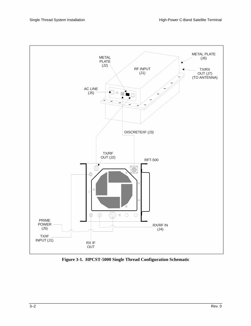
3Chapter 3. Single Thread Configuration
This chapter provides installation information for single thread configuration (Figure3-1) system, including:
! Unpacking and inspecting the parts! Installing the RFT! Installing the C-Band SSPA! Installing the LNA! External connections
WARNING
High Voltage Hazards:The HPCST-5000 utilizes high voltage that can be lethal if contacted. Theterminal system components should not be operated without a coverunless the user is thoroughly familiar with its operation and experiencedwith high voltage.
RF Radiation Hazards:Prior to operation of terminal system, ensure that all microwaveconnections are securely fastened. Check that there is no microwaveleakage. Never operate the HPCST-5000 with an open waveguide.This amplifier is capable of generating high power microwave radiation,which can cause bodily harm.
Safety Summary:Equipment of this nature has inherent hazards. Operator or servicetechnicians should have training on the high-power satellite terminalsystems. When the HPCST-5000 cover is removed, high voltage may beexposed. Use extreme care when operating the amplifier with its coverremoved. Extreme physical injury may result if these warnings are notobserved.
Single Thread System Installation High-Power C-Band Satellite Terminal
3–2 Rev. 0
RX/RF IN(J4)
RFT-500
TX/RFOUT (J2)
PRIMEPOWER
(J5)
TX/IFINPUT (J1)
RX IFOUT
DISCRETE/IF (J3)
RF INPUT(J1)
METAL PLATE(J6)
TX/RXOUT (J7)
(TO ANTENNA)
AC LINE(J5)
METALPLATE
(J2)
Figure 3-1. HPCST-5000 Single Thread Configuration Schematic
High-Power C-Band Satellite Terminal Single Thread System Installation
Rev. 0 3–3
3.1 Unpacking
The HPCST-5000 terminal system is packaged in multiple, preformed, reusable foaminside a cardboard carton.
Before unpacking the carton components, ensure that there is plenty of room around thecarton for workspace. A large work table is recommended.
To remove the parts:
1. Cut the tape at the top of the carton where it is indicated OPEN THIS END.2. Lift out the cardboard/foam spacer covering the unit.3. Remove each part from the carton.
CAUTION
Because the RFT and C-Band SSPA are heavy, assistance may benecessary to remove the unit from the box.
Note: Save the packing material for reshipment.
Single Thread System Installation High-Power C-Band Satellite Terminal
3–4 Rev. 0
3.2 Inspecting the Equipment
1. Carefully check the equipment for possible damage incurred during shipment.
2. Carefully check the equipment against the packing list shipped with theequipment to ensure that the shipment is complete.
3.2.1 Included Parts
A typical HPCST-5000 single thread configuration contains the following components.
Notes:1. Hardware required for this configuration is located in Chapter 8, Equipment List.2. Because each system can be custom ordered, it is beyond the scope of this
manual to provide the unlimited configuration possibilities.3. This chapter does not describe the installation procedures for amplifiers, or high
performance LNAs.
Qty. Description Qty. Description1 RFT outdoor unit
1 Low noise amplifier (LNA)
RF
INR
FO
UT
MO
DE
LN
O.
SE
RIA
LN
O.
FR
EQ
UE
NC
YN
OIS
ET
EM
PG
AIN
.1 C-Band SSPA 1 Installation and operation manuals for the
following:! HPCST-5000! Monitor and Control Software
1 Envelope containing the test data sheet
High-Power C-Band Satellite Terminal Single Thread System Installation
Rev. 0 3–5
3.3 RFT Installation
At the customer’s discretion, the RFT can be installed anywhere on or near the antenna.The supplied hardware allows the installer a wide range of installation alternatives,including:
! Vertical pole (e.g., mast) (either square or round). This is the most typicalinstallation.
CAUTION
Ensure that all air inlets, exhausts, and fan guards are free of dirt,dust, and debris. Make certain that these areas are inspected on aregular basis. Damage to the equipment can be the result.
! Within the hub of a large antenna.
! Spar (i.e., square bar) on the antenna structure.
Note: EFData recommends that the RFT be mounted vertically, with the air inletfacing the ground.
Single Thread System Installation High-Power C-Band Satellite Terminal
3–6 Rev. 0
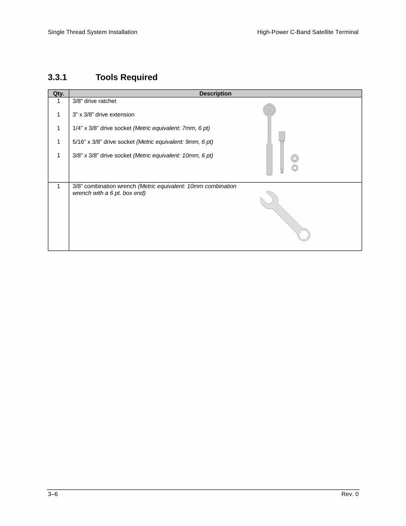
3.3.1 Tools Required
Qty. Description1
1
1
1
1
3/8” drive ratchet
3” x 3/8” drive extension
1/4” x 3/8” drive socket (Metric equivalent: 7mm, 6 pt)
5/16” x 3/8” drive socket (Metric equivalent: 9mm, 6 pt)
3/8” x 3/8” drive socket (Metric equivalent: 10mm, 6 pt)
1 3/8” combination wrench (Metric equivalent: 10mm combinationwrench with a 6 pt. box end)
High-Power C-Band Satellite Terminal Single Thread System Installation
Rev. 0 3–7
3.3.2 Vertical Pole Installation
Refer to Section 8, Equipment List, Figure 8-4 for assistance in the installation of theRFT using Mounting Kit P/N KT/3576. Refer to Figure 8-2, Cabling Configuration, forcables necessary to connect the single thread configuration.
3.3.2.1 Round Pole
Note: The following process is for a typical installation.
Install the RFT to a round vertical pole as follows:
1. Set the unit on its side, with the mounting holes facing up.
2. Install the 8” unistruts as follows:
a. Position an 8” unistrut (withthe open side facing up)over one set of the mountingholes on the RFT.
b. Using four 1/4-20 x 5/8”bolts, 1/4” splitlockwashers, and 1/4” flatwashers, attach an 8”unistrut to the RFT.
c. Tighten the bolts firmly.
d. Repeat Steps 2.a. and 2.b. for the second 8” unistrut.
Single Thread System Installation High-Power C-Band Satellite Terminal
3–8 Rev. 0
3. Install the 14” unistruts as follows:
a. Position a spring nutbetween the inner and outerbolts on both sides of each8” unistrut.
b. Install each spring nut asfollows:
(1) Place the spring nut inthe unistrut channel,spring side down, withits wide side parallelwith the unistrutchannel.
(2) Press down on thespring nut to compressthe spring, and rotatethe nut 90" (i.e.,perpendicular to theunistrut).
(3) Release pressure on the spring nut.
(4) Repeat Steps 3.b.(1) through 3.b.(3) for each spring nut.
High-Power C-Band Satellite Terminal Single Thread System Installation
Rev. 0 3–9
c. Position a 14” unistrut(open side facing up) overone of the 8” unistruts.
Note: Ensure the 14”unistrut is centered over theRFT.
d. Using two 5/16-18 x 1-1/4”bolts, 5/16” splitlockwashers, and 5/16” flatwashers, attach the 14”unistrut to the 8” unistrut.
Note: The bolts should be installed in the fifth hole from each end, asillustrated.
e. Tighten the bolts firmly.
f. Attach the second 14” unistrut to the second 8” unistrut by repeatingSteps 3.a. through 3.d.
Single Thread System Installation High-Power C-Band Satellite Terminal
3–10 Rev. 0
4. Install the pipe blocks as follows:
a. Install two spring nuts in each of four 14” unistruts (the two just mounted onthe RFT, and two additional).
Note: Ensure the spring nuts in the unistruts are wide enough apart so thatwhen the pipe blocks are installed, they will clear the pole when the unit islifted into place for installation.
b. Install each spring nut as follows:
(1) Place the springnut in the unistrutchannel, springside down, withits wide sideparallel with theunistrut channel.
(2) Press down on the spring nut to compress the spring, and rotate the nut90" (i.e., perpendicular to the unistrut).
(3) Release pressure on the spring nut.
(4) Repeat Steps 4.b.(1) through 4.b.(3) for each spring nut.
c. Using four 5/16-18 x 1” bolts, 5/16”split lockwashers, and 5/16” flatwashers, loosely secure the pipeblocks to the spring nuts.
Note: Ensure the pipe blocks areinstalled with the long angle facinginward, toward the pipe.
CAUTION
DO NOT tighten the pipe block bolts until after mounting the RFTon the vertical pole. (See Step 6.e.)
High-Power C-Band Satellite Terminal Single Thread System Installation
Rev. 0 3–11
5. Install the threaded rods as follows:
a. Install two spring nuts in both 14”unistruts mounted on the RFT.
Note: Ensure the spring nuts arepositioned over the outer holes in the14” unistruts.
b. To install each spring nut:
(1) Place the spring nut in theunistrut channel, spring sidedown, with its wide side parallelwith the unistrut channel.
(2) Press down on the spring nut tocompress the spring, and rotatethe nut 90" (i.e., perpendicular tothe unistrut).
(3) Release pressure on the spring nut.
(4) Repeat Steps 5.b.(1) through 5.b.(3) for each spring nut.
c. Thread a 5/16-20 nut approximately1-1/2” onto each threaded rod. (Thiswill ensure that the threaded rods willextend beyond the spring nuts wheninstalled.)
d. Place a 5/16” split lockwasher, 5/16”flat washer, and flat fitting plate overeach threaded rod.
Single Thread System Installation High-Power C-Band Satellite Terminal
3–12 Rev. 0
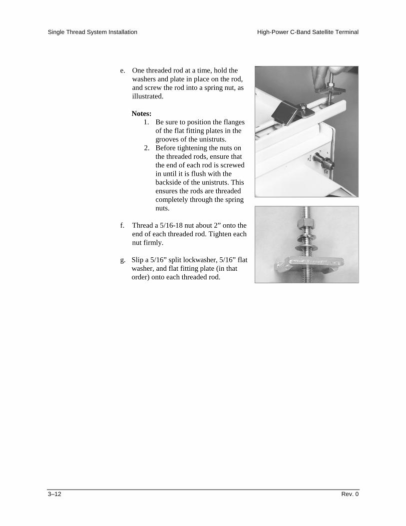
e. One threaded rod at a time, hold thewashers and plate in place on the rod,and screw the rod into a spring nut, asillustrated.
Notes:1. Be sure to position the flanges
of the flat fitting plates in thegrooves of the unistruts.
2. Before tightening the nuts onthe threaded rods, ensure thatthe end of each rod is screwedin until it is flush with thebackside of the unistruts. Thisensures the rods are threadedcompletely through the springnuts.
f. Thread a 5/16-18 nut about 2” onto theend of each threaded rod. Tighten eachnut firmly.
g. Slip a 5/16” split lockwasher, 5/16” flatwasher, and flat fitting plate (in thatorder) onto each threaded rod.
High-Power C-Band Satellite Terminal Single Thread System Installation
Rev. 0 3–13
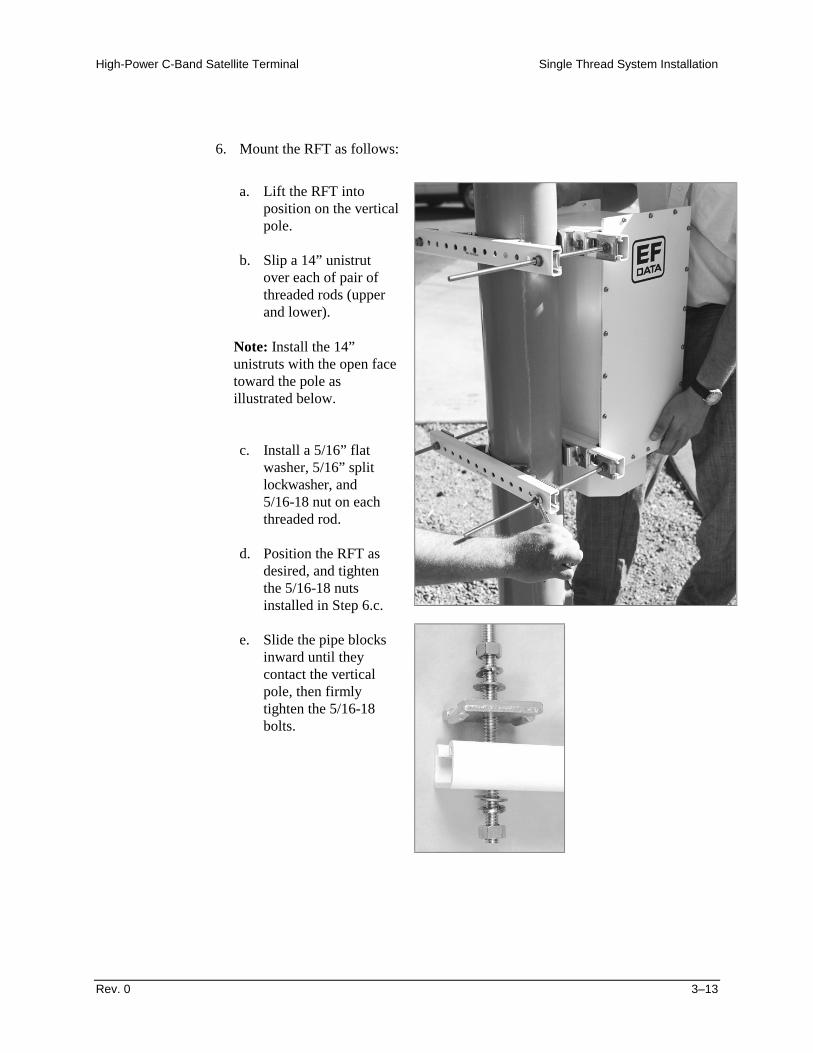
6. Mount the RFT as follows:
a. Lift the RFT intoposition on the verticalpole.
b. Slip a 14” unistrutover each of pair ofthreaded rods (upperand lower).
Note: Install the 14”unistruts with the open facetoward the pole asillustrated below.
c. Install a 5/16” flatwasher, 5/16” splitlockwasher, and5/16-18 nut on eachthreaded rod.
d. Position the RFT asdesired, and tightenthe 5/16-18 nutsinstalled in Step 6.c.
e. Slide the pipe blocksinward until theycontact the verticalpole, then firmlytighten the 5/16-18bolts.
Single Thread System Installation High-Power C-Band Satellite Terminal
3–14 Rev. 0
3.3.2.2 Square Pole
For square vertical pole installation, follow the steps in Section 2.3.2.1, with thefollowing exceptions:
! Do not perform Step 4.! Do not perform Step 6.e.
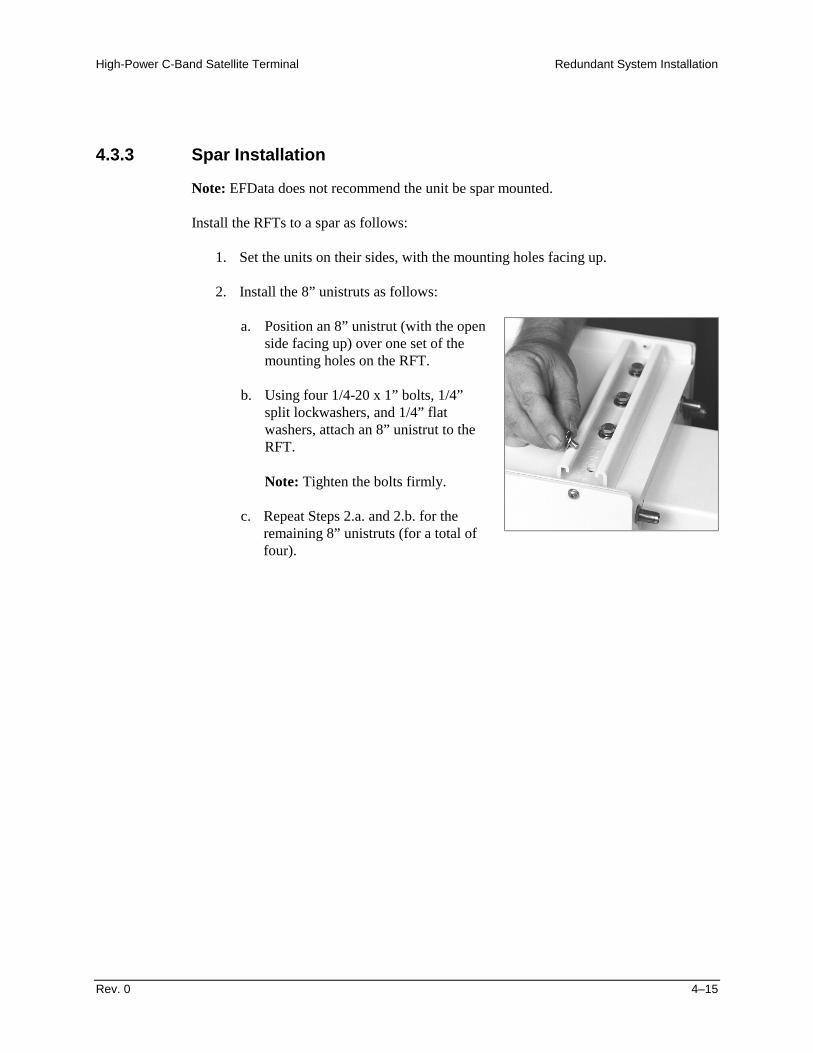
3.3.3 Spar Installation
Note: Refer to Section 8, Equipment List, Figure 8-3 for assistance in the installation.
Install the RFT to a spar as follows:
1. Set the unit on its side, with the mounting holes facing up.
2. Install the 8” unistruts as follows:
a. Position an 8” unistrut (with the openside facing up) over one set of themounting holes on the RFT.
b. Using four 1/4-20 x 1” bolts, 1/4”split lockwashers, and 1/4” flatwashers, attach an 8” unistrut to theRFT. Tighten the bolts firmly.
c. Repeat Steps 2.a. and 2.b. for thesecond 8” unistrut.
High-Power C-Band Satellite Terminal Single Thread System Installation
Rev. 0 3–15
3. Mount the RFT as follows:
a. Position a spring nut between theinner and outer bolts on both sidesof each 8” unistrut.
b. Install each spring nut as follows:
(1) Place the spring nut in theunistrut channel, spring sidedown, with its wide sideparallel with the unistrutchannel.
(2) Press down on the spring nutto compress the spring, androtate the nut 90" (i.e.,perpendicular to the unistrut).
(3) Release pressure on thespring nut.
(4) Repeat Steps 3.b.(1) through3.b.(3) for each spring nut.
c. Lift the RFT into position.
d. Using four 5/16-18 bolts, 5/16”split lockwashers, and 5/16” flatwashers, bolt the two spar supportbrackets in place. Tighten the boltsfirmly.
Single Thread System Installation High-Power C-Band Satellite Terminal
3–16 Rev. 0
3.4 LNA Installation
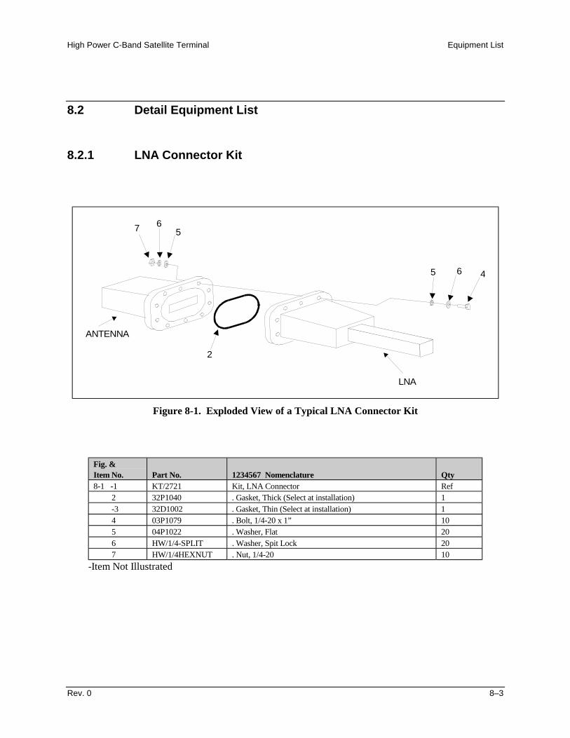
Note: Refer to Section 8, Figure 8-1, for assistance in the installation of the LNA usingthe LNA Connector Kit P/N KT/2721.
To install a single LNA (Figure 3-2) to an antenna:
1. Remove the protective cover from the antenna mount location (if installed).
2. Remove the plastic cover from the antenna end (RF IN) of the LNA.
3. Remove the plastic cover from the RF OUT end of the LNA.
CAUTION
After removing the protective cover(s), ensure that no foreignmaterial or moisture enters the antenna waveguide or LNA.
4. Install the appropriate gasket on the antenna end of the LNA:
a. If the LNA has a groove, and the antenna flange does not, the thin gasketshould be used.
b. If both the LNA and the antenna flange have grooves, the thick gasket shouldbe used.
Figure 3-2. Installation of the LNA
High-Power C-Band Satellite Terminal Single Thread System Installation
Rev. 0 3–17
5. Position the LNA in place on the antenna, and install the 1/4-20 x 1” bolts,washers, and nuts as shown in Figure 3-3. Do not tighten at this time.
CAUTION
Install the hardware exactly as shown. Failure to do so may causedamage to the LNA and/or waveguide.
6. After all the bolts, washers, and nuts have been installed, tighten them accordingto the following illustrated sequence.
1
2
3
4
5
6
7
89
10
Figure 3-3. Procedures for Tightening the Waveguide Bolts
Single Thread System Installation High-Power C-Band Satellite Terminal
3–18 Rev. 0
3.5 C-Band SSPA Installation
Refer to Section 8, Equipment List, Figure 8-4, for assistance in the installation of theC-Band SSPA using the Universal Mounting Kit P/N KT/6699. Refer to Figure 8-2Cabling Configuration for cables necessary to connect the single thread configuration.
3.5.1 C-Band SSPA Installation
At the customer’s discretion, the C-Band SSPA can be installed anywhere on or near theantenna. The supplied hardware allows the installer a wide range of installationalternatives, including:
! Vertical pole (e.g., mast) (either square or round). This is the most typicalinstallation.
! Within the hub of a large antenna.
! Spar (i.e., square bar) on the antenna structure.
Note: EFData recommends that the C-Band SSPA be mounted either vertically,as shown, or with the fan assembly facing the ground.
High-Power C-Band Satellite Terminal Single Thread System Installation
Rev. 0 3–19
3.5.2 Vertical Pole Installation
3.5.2.1 Round Pole
Note: The following process is for a typical installation.
Install the C-Band SSPA to a round vertical pole as follows:
1. Install mounting bracket as follows:
a. Position two mountingbrackets onto theC-Band SSPA.
b. Secure the mounting
brackets to the unitwith four 3/8 x 1 1/4”bolts, 3/8” splitlockwashers, 3/8 flatwashers, and 3/8 hexnuts.
2. Install the 14” unistruts as follows:
a. Position an 14” unistrut(with the open side facingup) over the mounting holesof the mounting bracket.
b. Using four 3/8 x 1” bolts,3/8” split lockwashers, and3/8” flat washers, attach an8” unistrut to the C-BandSSPA mount bracket.Tighten the bolts firmly.
c. Repeat Steps 3.a. and 2.b.for the second 14” unistrut.
Single Thread System Installation High-Power C-Band Satellite Terminal
3–20 Rev. 0
3. Install the spring nuts as follows:
a. Position a spring nutbetween the inner and outerbolts on both sides of each14” unistrut.
b. Install each spring nut asfollows:
(1) Place the spring nut inthe unistrut channel,spring side down, withits wide side parallelwith the unistrutchannel.
(2) Press down on thespring nut to compressthe spring, and rotatethe nut 90" (i.e.,perpendicular to theunistrut.
(3) Release pressure on the spring nut.
(4) Repeat Steps 4.b.(1) through 4.b.(3) for each spring nut.
High-Power C-Band Satellite Terminal Single Thread System Installation
Rev. 0 3–21
4. Install the pipe blocks as follows:
Note: Be sure to position the spring nuts in the unistruts wide enough apart sothat when the pipe blocks are installed they will clear the pole when the unit islifted into place for installation.
a. Using four 5/16-18 x 1” bolts, 5/16”split lockwashers, and 5/16” flatwashers, loosely secure the pipeblocks to the spring nuts.
Note: Ensure the pipe blocks areinstalled with the long angle facinginward, toward the pipe, asillustrated.
CAUTION
DO NOT tighten the pipe block bolts until after mounting the C-BandSSPA on the vertical pole. (See Step 6.e.)
Single Thread System Installation High-Power C-Band Satellite Terminal
3–22 Rev. 0
5. Install the threaded rods as follows:
a. Install two spring nuts in both 14”unistruts mounted on the C-BandSSPA.
Note: Ensure the spring nuts arepositioned over the outer holes in the14” unistruts, as illustrated.
b. To install each spring nut:
(1) Place the spring nut in theunistrut channel, spring sidedown, with its wide side parallelwith the unistrut channel.
(2) Press down on the spring nut tocompress the spring, and rotatethe nut 90" (i.e., perpendicular tothe unistrut).
(3) Release pressure on the spring nut.
(4) Repeat Steps 5.b.(1) through 5.b.(3) for each spring nut.
c. Thread a 5/16-20 nut approximately1-1/2” onto each threaded rod. (Thiswill ensure that the threaded rods willextend beyond the unistrut wheninstalled.)
d. Place a 5/16” split lockwasher, 5/16”flat washer, and flat fitting plate overeach threaded rod.
High-Power C-Band Satellite Terminal Single Thread System Installation
Rev. 0 3–23
e. One threaded rod at a time, hold thewashers and plate in place on the rod,and screw the rod into a spring nut, asillustrated.
Notes:1. Be sure to position the flanges of the flat fitting plates in the grooves
of the unistruts.2. Before tightening the nuts on the threaded rods, ensure that the end
of each rod is screwed in until it is flush with the backside of theunistruts. This ensures the rods are threaded completely through thespring nuts.
f. Tighten each nut firmly.
g. Thread a 5/16-18 nut about 2” onto the end of each threaded rod.
h. Slip a 5/16” split lockwasher, 5/16” flat washer, and flat fitting plate (in thatorder) onto each threaded rod.
Single Thread System Installation High-Power C-Band Satellite Terminal
3–24 Rev. 0
6. Mount the C-Band SSPA as follows:
a. Lift the C-Band SSPAinto position on thevertical pole.
b. Slip a 14” unistrutover each of pair ofthreaded rods (upperand lower).
Note: Install the 14”unistruts with the open facetoward the pole asillustrated below.
c. Install a 5/16” flatwasher, 5/16” splitlockwasher, and5/16-18 nut on eachthreaded rod.
d. Position the RFT asdesired, and tightenthe 5/16-18 nutsinstalled in Step 6.c.
e. Slide the pipe blocksinward until theycontact the verticalpole, then firmlytighten the 5/16-18bolts.
High-Power C-Band Satellite Terminal Single Thread System Installation
Rev. 0 3–25
3.5.2.2 Square Pole
For square vertical pole installation, follow the steps in Section 2.3.2.1, with thefollowing exceptions:
! Do not perform Step 4.! Do not perform Step 6.e.
Single Thread System Installation High-Power C-Band Satellite Terminal
3–26 Rev. 0
3.5.3 Spar Installation
Note: Refer to Section 8, Equipment List, Figure 8-3 for assistance in the installation.
Install the C-Band SSPA to a spar as follows:
1. Install mounting bracket as follows:
a. Position two mountingbrackets onto theC-Band SSPA.
b. Secure the mounting
brackets to the unitwith four 3/8 x 1 1/4”bolts, 3/8” splitlockwashers, 3/8 flatwashers, and 3/8 hexnuts.
2. Install the 14” unistruts as follows:
a. Position an 14” unistrut(with the open side facingup) over the mounting holesof the mounting bracket.
b. Using four 3/8 x 1” bolts,3/8” split lockwashers, and3/8” flat washers, attach an8” unistrut to the C-BandSSPA mount bracket.Tighten the bolts firmly.
c. Repeat Steps 3.a. and 2.b.for the second 14” unistrut.
High-Power C-Band Satellite Terminal Single Thread System Installation
Rev. 0 3–27
3. Mount the C-Band SSPA as follows:
a. Position a spring nut between theinner and outer bolts on both sidesof each 14” unistrut, as illustrated.
b. Install each spring nut as follows:
(1) Place the spring nut in theunistrut channel, spring sidedown, with its wide sideparallel with the unistrutchannel.
(2) Press down on the spring nutto compress the spring, androtate the nut 90" (i.e.,perpendicular to the unistrut).
(3) Release pressure on thespring nut.
(4) Repeat Steps 3.b.(1) through3.b.(3) for each spring nut.
c. Lift the C-Band SSPA into position.
d. Using four 5/16-18 bolts, 5/16” split lockwashers, and 5/16” flat washers,bolt the two spar support brackets in place.
e. Tighten the bolts firmly.
Single Thread System Installation High-Power C-Band Satellite Terminal
3–28 Rev. 0
This page is intentionally left blank.
Rev. 0 4–1
4Chapter 4. REDUNDANT SYSTEM
INSTALLATION
This chapter provides installation information for redundant system (Figure 4-1)including:
! Unpacking and inspecting the parts! Installing redundant RFTs! Installing redundant C-Band SSPAs! Installing the 1:1 redundant plate! External connections
Note: Refer to Section 4.4 for the redundancy configuration cabling matrix.
Redundant System Installation High-Power C-Band Satellite Terminal
4–2 Rev. 0
RX
I/O
M&CSYSTEM
J15 J5
TX
1
J14
IF
IF
RSU503L
J4
J8
J2
J2SW
IF TEST INPUT
DISCRETES
IF TEST OUTPUT
LNA PLATE ASSEMBLY
TXRX
IJ16
J6
70 MHz/140 MHz
INDOOR UNITS(NOT PART
OF SYSTEM)
OUTDOOR UNITS
HPCST-5000 REDUNDANT SYSTEM
J1
J3 J6
RFT-500 #A J4
J2
M&CJ3
J1J7
J3
J1J7
ANTENNASYSTEM
(REFERENCEONLY)
SSPA REDUNDANTASSEMBLY (AS/6494)
C-BANDSSPA
#A
W/G
W/G
ANTENNA
W/G
W/GLNA #A
LNA #B
TXFILTER
40 dB*FRWD
40 dB*FRWD
M&C
C-BANDSSPA
#B
TX
J4
J6
RFT-500 #B
J3
J2
IF RF
IF RF
COAX
COAX
*OPTIONAL
Figure 4-1. HPCST-5000 Redundant System Schematic Using SSPAs
High-Power C-Band Satellite Terminal Redundant System Installation
Rev. 0 4–3
4.1 Unpacking
Note: The HPCST-5000 terminal system is shipped in multiple cartons.
Remove the parts as follows:
1. Cut the tape at the top of each carton where it is indicated OPEN THIS END.
2. Lift out the cardboard/foam spacer covering the units.
CAUTION
1. The redundant assembly may be too heavy to be removed by oneindividual, assistance may be required.
2. Do not lift the redundant SSPA assembly by the waveguide. Liftassembly by the mounting frame only. Extreme care shall be givento the waveguide assembly during removal. Damage to theredundant assembly may be the result.
3. Remove the parts from the cartons. Refer to Section 4.2.1 for a parts breakdown.
4. If required, remove the screws from the lid of the wooden crate, and remove thelid.
5. Unbolt and remove the redundant LNA plate from the crate.
6. Remove the remainder of the parts from the crate. Refer to Section 4.2.1 for aparts breakdown.
Note: Save the packing material for reshipment, if required.
Redundant System Installation High-Power C-Band Satellite Terminal
4–4 Rev. 0
4.2 Inspecting the Equipment
1. Carefully check the equipment for possible damage incurred during shipment.
2. Carefully check the equipment against the packing list shipped with theequipment to ensure that the shipment is complete.
4.2.1 Included Parts
A typical redundant HPCST-5000 configuration contains the following components.
Notes:1. Hardware required to perform this task is located in Chapter 8, Equipment List.2. Because each system can be custom ordered, it is beyond the scope of this
manual to provide the unlimited configuration possibilities.3. This chapter does not describe the installation procedures for amplifiers, high
performance LNAs, phase-locked LNBs, LNBs, and phase-locked blockconverters.
High-Power C-Band Satellite Terminal Redundant System Installation
Note: Pictured is a typical LNA. Other LNAsare available, and can be ordered from anEFData marketing representative.
1 RSU-503L 1 Envelope containing the test data sheet
1 Monitor and Control Software for EFDataSatellite Terminals User’s Guide
1 HPCST-5000 installation and operationmanual
Note: Can be obtained in CD or paperformat.
1 RS-503 installation and operation manual 1 Redundant Assembly
Redundant System Installation High-Power C-Band Satellite Terminal
4–6 Rev. 0
4.3 RFT Installation
CAUTION
Ensure that all air inlets, exhausts, and fan guards are free of dirt, dust, anddebris. Make certain that these areas are inspected on a regular basis.Damage to the equipment can be the result.
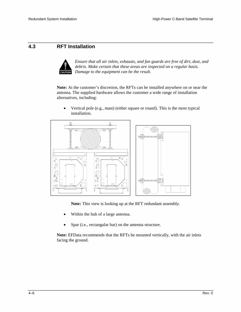
Note: At the customer’s discretion, the RFTs can be installed anywhere on or near theantenna. The supplied hardware allows the customer a wide range of installationalternatives, including:
! Vertical pole (e.g., mast) (either square or round). This is the most typicalinstallation.
Note: This view is looking up at the RFT redundant assembly.
! Within the hub of a large antenna.
! Spar (i.e., rectangular bar) on the antenna structure.
Note: EFData recommends that the RFTs be mounted vertically, with the air inletsfacing the ground.
High-Power C-Band Satellite Terminal Redundant System Installation
Rev. 0 4–7
4.3.1 Tools Required
Qty. Description1
1
1
1
3” x 3/8” drive extension
1/4” x 3/8” drive socket (Metric equivalent: 7mm, 6 pt)
5/16” x 3/8” drive socket (Metric equivalent: 9mm, 6 pt)
3/8” x 3/8” drive socket (Metric equivalent: 10mm, 6 pt)
1 3/8” combination wrench (Metric equivalent: 10mm combinationwrench with a 6 pt. box end)
Redundant System Installation High-Power C-Band Satellite Terminal
4–8 Rev. 0
4.3.2 Vertical Pole Installation
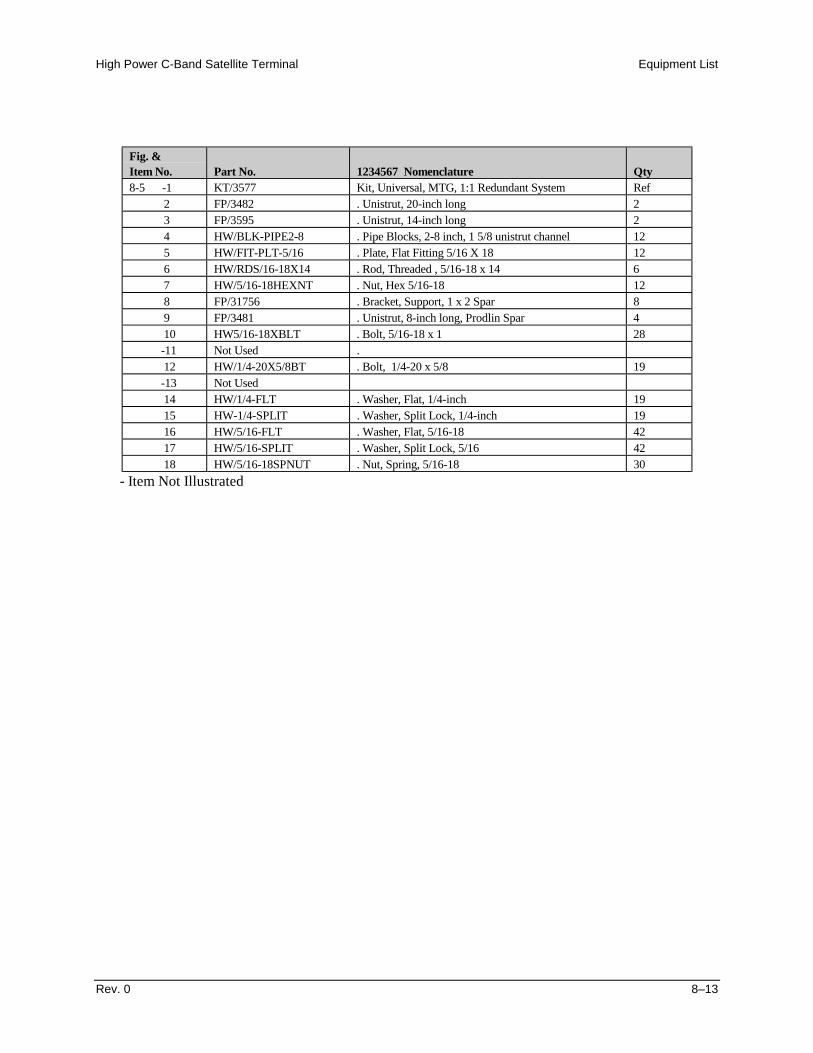
Refer to Section 8, Equipment List, Figure 8-5, for assistance in the installation of theRFT. Refer to Figure 8-2 for the cabling configuration.
4.3.2.1 Round Pole
Note: The following process is a typical installation.
Install the RFTs to a round vertical pole as follows:
1. Set the units on their sides, with the mounting holes facing up.
2. Install the 8” unistruts as follows:
a. Position an 8” unistrut (withthe open side facing up) overone set of the mounting holeson the RFT.
b. Using four 1/4-20 x 1” bolts,1/4” split lockwashers, and1/4” flat washers, attach an 8”unistrut to the RFT.
Note: Tighten the bolts firmly.
c. Repeat Steps 2.a. and 2.b. foreach of the remaining 8”unistruts (four required).
High-Power C-Band Satellite Terminal Redundant System Installation
Rev. 0 4–9
3. Install the 20” unistruts as follows:
Note: The placement of the pipe blocks may interfere with the inner or centerunistrut attaching bolts. Be sure to determine the pipe block placement locationsbefore bolting the 20” unistruts in place. It may be necessary to eliminate thecenter or inner 20” unistrut mounting spring nuts and bolts.
a. Insert a spring nut betweenthe unistrut mounting boltson both RFTs.
b. To install each spring nut:
(1) Place the spring nut inthe unistrut channel,spring side down, withits wide side parallelwith the unistrutchannel.
(2) Press down on thespring nut to compressthe spring, and rotatethe nut 90" (i.e.,perpendicular to theunistrut).
(3) Release pressure on the spring nut.
(4) Repeat Steps 3.b.(1) through 3.b.(3) for each spring nut.
Redundant System Installation High-Power C-Band Satellite Terminal
4–10 Rev. 0
c. With the RFTs side-by-side,position a 20” unistrut(open side facing up) inplace over one pair of 8”unistruts.
Note: Ensure the longunistrut is centered over theRFT.
d. Using two or three 5/16-18x 1-1/4” bolts, 5/16” splitlockwashers, and 5/16” flatwashers, attach the 20”unistrut to the 8” unistruts.
e. Tighten bolts firmly.
f. Attach the second 20” unistrut to the second set of 8” unistruts by repeatingSteps 3.a. through 3.d.
High-Power C-Band Satellite Terminal Redundant System Installation
Rev. 0 4–11
4. Install the pipe blocks as follows:
a. Install two spring nuts in each of the two 20” long unistruts and two 14” longunistruts (centered in the unistruts, and wide enough apart so the pipe blockswill clear the pole when the unit is installed).
b. Install each spring nutas follows:
(1) Place the spring nut in the unistrut channel, spring side down, with itswide side parallel with the unistrut channel.
(2) Press down on the spring nut to compress the spring, and rotate the nut90" (i.e., perpendicular to the unistrut).
(3) Release pressure on the spring nut.
(4) Repeat Steps 4.b.(1) through 4.b.(3) for each spring nut.
c. Using eight 5/16-18 x1” bolts, 5/16” splitlockwashers, and5/16” flat washers,loosely secure the pipeblocks to the springnuts.
Notes:1. Ensure the pipe blocks are installed with the long angle face inward, toward
the pipe, as illustrated.2. DO NOT tighten the pipe block bolts until after mounting the RFTs on the
vertical pole. (See Step 6.e.)
Redundant System Installation High-Power C-Band Satellite Terminal
4–12 Rev. 0
5. Install the threaded rods as follows:
a. Install two spring nuts in both20” unistruts mounted on theRFT.
b. Install each spring nut asfollows:
(1) Place the spring nut inthe unistrut channel,spring side down, withits wide side parallelwith the unistrutchannel.
(2) Press down on the springnut to compress thespring, and rotate the nut90" (i.e., perpendicularto the unistrut).
(3) Release pressure on the spring nut.
(4) Repeat Steps 5.b.(1) through 5.b.(3) for each spring nut.
c. Thread a 5/16-20 nut approximately 1-1/2” onto each threaded rod. (Thiswill ensure that the threaded rods will extend beyond the spring nuts wheninstalled.)
d. Place a 5/16” split lockwasher, 5/16” flat washer, and flat fitting plate overeach threaded rod.
High-Power C-Band Satellite Terminal Redundant System Installation
Rev. 0 4–13
e. One threaded rod at a time,hold the washers and plate inplace on the threaded rod andscrew it into a spring nut.
Notes:1. Be sure to position the flanges of the flat fitting plates in the grooves of
the unistruts.2. Before tightening the nuts on the threaded rods, ensure that the end of
each rod is screwed in until it contacts the unistrut. This ensures the rodsare threaded completely through the spring nuts
f. Tighten each nutfirmly.
g. Thread a 5/16-18 nutabout 2” onto the endof each threaded rod.
h. Slip a 5/16” splitlockwasher, 5/16” flatwasher, and flat fittingplate (in that order)onto each threadedrod.
Redundant System Installation High-Power C-Band Satellite Terminal
4–14 Rev. 0
6. Mount the RFTs as follows:
a. Lift the RFT into position onthe vertical pole.
b. Slip a 14” unistrut over eachof pair of threaded rods(upper and lower).
Note: Install the 14” unistrutswith the open face toward thepole, as illustrated.
c. Install a 5/16” flat washer,5/16” split lockwasher, and5/16-18 nut on each threadedrod.
d. Position the RFT, as desired,and tighten the 5/16-18 nutsinstalled in Step 6.c.
e. Slide the pipe blocks in untilthey contact the vertical pole.
f. Then, firmly tighten the nuts.
4.3.2.2 Square Pole
For square, vertical pole installation, follow the steps in Section 3.3.2.1, with thefollowing exceptions:
! Do not perform Step 4.! Do not perform Step 6.e.
High-Power C-Band Satellite Terminal Redundant System Installation
Rev. 0 4–15
4.3.3 Spar Installation
Note: EFData does not recommend the unit be spar mounted.
Install the RFTs to a spar as follows:
1. Set the units on their sides, with the mounting holes facing up.
2. Install the 8” unistruts as follows:
a. Position an 8” unistrut (with the openside facing up) over one set of themounting holes on the RFT.
b. Using four 1/4-20 x 1” bolts, 1/4”split lockwashers, and 1/4” flatwashers, attach an 8” unistrut to theRFT.
Note: Tighten the bolts firmly.
c. Repeat Steps 2.a. and 2.b. for theremaining 8” unistruts (for a total offour).
Redundant System Installation High-Power C-Band Satellite Terminal
4–16 Rev. 0
3. Install the 20” unistruts as follows:
a. Position a spring nutbetween the 1/4-20bolts in each 8”unistrut.
b. Install each spring nut as follows:
(1) Place the spring nut in the unistrut channel, spring side down, with itswide side parallel with the unistrut channel.
(2) Press down on the spring nut to compress the spring, and rotate the nut90".
(3) Release pressure on the spring nut.
c. With the RFTs side byside, position a 20”unistrut in place overone pair of 8” unistruts(open side up).
d. Using four 5/16-18bolts, 5/16” splitlockwashers, and5/16” flat washers,bolt the 20” unistrut tothe 8” unistruts.
e. Tighten the boltsfirmly.
f. Repeat Steps 3.c.through 3.e. for thesecond 20” unistrut.
High-Power C-Band Satellite Terminal Redundant System Installation
Rev. 0 4–17
4. Mount the RFT as follows:
a. Lift the RFT into position.
b. Using four 5/16-18 bolts, 5/16”split lockwashers, and 5/16” flatwashers, bolt the two spar supportbrackets in place. Tighten the boltsfirmly.
Redundant System Installation High-Power C-Band Satellite Terminal
4–18 Rev. 0
4.3.4 1:1 Redundant Plate Installation
Note: Refer to Section 8, Figure 8-2 for cabling configuration.
The 1:1 redundant plate is shown in Figure 4-2 as follows:
Figure 4-2. 1:1 Redundant Plate
Install the 1:1 redundant plate as follows:
1. Mount the 1:1 redundant plate to the antenna.
Note: The type of mounting is determined by the brand of antenna on which theequipment will be installed.
2. Remove the plastic cover from the RF IN connector of the redundant plate.
CAUTION
After removing the protective cover, ensure that no foreign materialor moisture enters the 1:1 redundant plate’s waveguide.
High-Power C-Band Satellite Terminal Redundant System Installation
Rev. 0 4–19
3. Install the appropriate gasket on the RF IN connector of the redundant plate:
a. If the TR Filter-Plate/waveguide has a groove, and the antenna flange doesnot, the thin gasket should be used.
b. If both the TR Filter-Plate/waveguide and the antenna flange have grooves,the thick gasket should be used.
4. Position the antenna waveguide in place on the RF IN connector, and install the1/4-20 x 1” bolts, 1/4” split lockwashers, 1/4” flat washers, and 1/4-20 nuts asshown in Figure 4-3.
Note: Do not tighten the bolts at this time.
Figure 4-3. Installation of LNA to Waveguide
Redundant System Installation High-Power C-Band Satellite Terminal
4–20 Rev. 0
5. After all the bolts, washers, and nuts have been installed, tighten bolts accordingto Figure 4-4.
6. Remove the plastic covers from all the connectors, and attach the appropriatecables.
1
2
3
4
5
6
7
89
10
Figure 4-4. Procedures for Tightening LNA to Waveguide Bolts
High-Power C-Band Satellite Terminal Redundant System Installation
Rev. 0 4–21
4.3.5 1:1 Redundant C-Band SSPA Installation
Refer to Section 8, Equipment List, Figure 8-6 for assistance in the installation of the1:1 Redundant System. Refer to Figure 8-2 for the cabling configuration.
4.3.5.1 Round Pole
Note: The following process is for a typical installation.
Install the 1:1 redundant assembly C-Band SSPAs to a round vertical pole as follows:
1. Set the units on a suitable work bench with the cooling fan side up. 2. Install the mounting bracket as follows:
a. Position the mountingbrackets. Align themounting bracketswith the mounting boltholes.
CAUTION
Do not block the cooling fans with the mounting bracket. Damageto the unit may be the result
b. Install four 3/8 x 11/4” bolts 3/8” split washers, and 3/8” flat washers.
c. Tighten bolts firmly.
Redundant System Installation High-Power C-Band Satellite Terminal
4–22 Rev. 0
3. Install 20” unistrut as follows:
Note: The placement of the pipe blocks may interfere with the inner or centerunistrut attaching bolts. Be sure to determine the pipe block placement locationsbefore bolting the 20” unistrut in place. It may be necessary to eliminate theinner or center mounting spring nuts and bolts.
a. Position an 20” unistrut (withthe open side facing up) overone set of the mounting holeson the C-Band SSPAs.
b. Using six 3/8-20 x 1” bolts,3/8” split lockwashers, and3/8” flat washers, attach the20” unistrut to the mountingbracket.
Note: Tighten the bolts firmly.
c. Repeat Steps 3.a. and 3.b. foreach of the remaining 20”unistruts (two required).
d. Insert a spring nut between theunistrut mounting bolts.
e. To install each spring nut:
(1) Place the spring nut in the unistrut channel, spring side down, with itswide side parallel with the unistrut channel.
(2) Press down on the spring nut to compress the spring, and rotate the nut90" (i.e., perpendicular to the unistrut).
(3) Release pressure on the spring nut.
(4) Repeat Steps 3.b.(1) through 3.b.(3) for each spring nut.
High-Power C-Band Satellite Terminal Redundant System Installation
Rev. 0 4–23
4. Install the pipe blocks as follows:
Note: Be sure to position the spring nuts in the unistruts wide enough apart sothat when the pipe blocks are installed they will clear the pole when the unit islifted into place for installation.
a. Using four 5/16-18 x 1” bolts, 5/16”split lockwashers, and 5/16” flatwashers, loosely secure the pipeblocks to the spring nuts.
Note: Ensure the pipe blocks areinstalled with the long angle facinginward, toward the pipe, asillustrated.
CAUTION
DO NOT tighten the pipe block boltsuntil after mounting the C-BandSSPA on the vertical pole. (SeeStep 6.e.)
Notes:1. Ensure the pipe blocks are installed with the long angle face inward, toward
the pipe, as illustrated.2. DO NOT tighten the pipe block bolts until after mounting the RFTs on the
vertical pole. (See Step 6.e.)
Redundant System Installation High-Power C-Band Satellite Terminal
4–24 Rev. 0
5. Install the threaded rods as follows:
a. Install two spring nuts in both20” unistruts mounted on theC-Band SSPAs.
b. Install each spring nut asfollows:
(1) Place the spring nut inthe unistrut channel,spring side down, withits wide side parallelwith the unistrutchannel.
(2) Press down on the spring nut to compress the spring, and rotate the nut90" (i.e., perpendicular to the unistrut).
(3) Release pressure on the spring nut.
(4) Repeat Steps 5.b.(1) through 5.b.(3) for each spring nut.
c. Thread a 5/16-20 nut approximately 1-1/2” onto each threaded rod. (Thiswill ensure that the threaded rods will extend beyond the unistrut wheninstalled.)
d. Place a 5/16” split lockwasher, 5/16” flat washer, and flat fitting plate overeach threaded rod.
High-Power C-Band Satellite Terminal Redundant System Installation
Rev. 0 4–25
Notes:1. Ensure the flanges of the flat fitting plates are in the grooves of the
unistruts.2. Before tightening the nuts on the threaded rods, ensure that the end of each
rod is screwed in until it contacts the unistrut. This ensures the rods arethreaded completely through the spring nuts.
e. One threaded rod at a time,hold the washers and plate inplace on the threaded rod andscrew it into a spring nut, asillustrated.
f. Thread a 5/16-18 nut about 2”onto the end of each threadedrod. Tighten each nut firmly.
g. Slip a 5/16” split lockwasher,5/16” flat washer, and flatfitting plate (in that order)onto each threaded rod.
Redundant System Installation High-Power C-Band Satellite Terminal
4–26 Rev. 0
6. Mount the C-Band SSPAs as follows:
a. Lift the configuration intoposition on the vertical pole.
b. Slip a 14” unistrut over eachof pair of threaded rods(upper and lower).
Note: Install the 14” unistrutswith the open face toward thepole, as illustrated.
c. Install a 5/16” flat washer,5/16” split lockwasher, and5/16-18 nut on each threadedrod.
d. Position the configuration, asdesired, and tighten the5/16-18 nuts installed inStep 6.c.
e. Slide the pipe blocks in untilthey contact the vertical pole.
f. Tighten the 5/16-18 bolts.
4.3.5.2 Square Pole
For square, vertical pole installation, follow the steps in Section 4.3.2.1, with thefollowing exceptions:
! Do not perform Step 4.! Do not perform Step 6.e.
High-Power C-Band Satellite Terminal Redundant System Installation
Rev. 0 4–27
4.3.6 Spar Installation
Note: EFData does not recommend the unit be spar mounted.
Install the C-Band SSPA to a spar as follows:
1. Set the C-Band SSPAs on their sides, with the mounting holes facing up.
2. Install the mounting bracket as follows:
a. Position the C-Band SSPA into themounting bracket. Secure with four3/8 x 1.25” bolts, 3/8 split lockwashers, and 3/8 flat washers.Tighten bolts firmly.
3. Install the 20” unistruts as follows:
a. Position the 20” unistrut on the mounting bracket and secure with six 3/8 x1.25 bolts, 3/8” split lock washers, and 3/8” flat washers.
b. Install each spring nutas follows:
(1) Place the springnut in the unistrutchannel, springside down, withits wide sideparallel with theunistrut channel.
(2) Press down on the spring nut to compress the spring, and rotate thenut 90".
Redundant System Installation High-Power C-Band Satellite Terminal
4–28 Rev. 0
4. Release pressure on the spring nut. Mount the configuration as follows:
a. Lift the C-Band SSPA into position.
b. Using four 5/16-18 bolts, 5/16”split lockwashers, and 5/16” flatwashers, bolt the two spar supportbrackets in place.
c. Tighten the bolts firmly.
4.4 Redundancy Configuration Cabling Matrix
Refer to Figure 4-5 to determine the proper length of cable assemblies needed to connectthe redundant configuration.
Note: Refer to Chapter 8 for the part number corresponding to the length of cablerequired for the redundant configuration. Contact EFData Customer Support forobtaining the required cable assemblies.
High-Power C-Band Satellite Terminal Redundant System Installation
Redundant System Installation High-Power C-Band Satellite Terminal
4–30 Rev. 0
This page is intentionally left blank.
Rev. 0 5–1
5Chapter 5. OPERATION
This chapter provides operation information for the HPCST-5000 terminal system.
5.1 System Operation
There are three methods of operating the RFT-500:
! Connect a PC running DOS to the EIA-232/EIA-485 remote control port, and runthe M&C system monitor software. This software is DOS-based and provides aninterface to the remote commands.
For information on the remote commands, refer to Appendix B.
For more information on the M&C system monitor program, refer to the Monitorand Control Software for EFData Satellite Terminals User’s Guide.
! Connect the optional KP-10 hand-held keypad. For more information, refer tothe KP-10 External Keypad Installation and Operation Manual.
! Use the optional front panel display/keypad (refer to Section 5.3).
5.2 Remote Control
Refer to Appendix B for information on remote control operation.
Operation High-Power C-Band Satellite Terminal
5–2 Rev. 0
5.3 Front Panel Display/Keypad
The optional front panel (Figure 5-1) provides the local user interface, which can be usedto configure and monitor the status of the terminal.
Figure 5-1. Optional RFT-500 Terminal Keypad
The front panel features a 16-character, 2-line LED display and a 6-key keypad. Allfunctions are accessible at the front panel by entering one of three predefined “SELECT”categories or levels:
! Configuration (CONFIG)! Monitor! Faults
High-Power C-Band Satellite Terminal Operation
Rev. 0 5–3
5.3.1 Front Panel Controls
The terminal is locally operated by using the front panel keypad. The keypad consists ofsix keys. Each key has its own logical function or functions.
Key Description[ENTER] This key is used to select a displayed function or to execute a change to the terminal’s
configuration.[CLEAR] This key is used for backing out of a selection or to cancel a configuration change
which has not been executed using [ENTER]. Pressing [CLEAR] generally returns thedisplay to the previous selection.
["] and [#] These keys are used to move to the next selection, or to move the cursor for certainfunctions.
[$] and [%] These keys are used primarily to change configuration data (numbers), but are alsoused at times to move from one section to another.
The terminal front panel control uses a tree-structured menu system (Figure 5-2 throughFigure 5-5) to access and execute all functions. The base level of this structure is thesign-on message, which is displayed at the front panel upon terminal power-up.
! Line 1 of the sign-on message displays the terminal model number.! Line 2 displays the version number of the firmware implemented in the terminal.
The main level of the menu system is the SELECT menu, which may be accessed fromthe base level by pressing any of the arrow keys. From the SELECT menu, any one ofthree functional categories may be selected:
Press ["] or [#] to move from one selection to another.
When the desired function is displayed on line 2, that level can be entered by pressing[ENTER]. Once the functional level has been entered, move to the desired function bypressing ["] or [#].
Operation High-Power C-Band Satellite Terminal
5–4 Rev. 0
5.4 Main Menu
Refer to Figure 5-2.
The following sections contain information about individual menu categories and theirfunctions.
Note: The firmware/software referenced in this manual may be an earlier version of theactual firmware/software supplied with the unit.
RFT-500VER: 7.00 or
VER: 8:00
SELECTCONFIG
(Figure 5-3)
SELECTMONITOR(Figure 5-4)
SELECTFAULTS
(Figure 5-5)
ACCESS TOSUBMENU
CONDITIONAL OROPTION-DEPENDENT
Parameter Information
Key:
Figure 5-2. Main Menu
High-Power C-Band Satellite Terminal Operation
Rev. 0 5–5
5.4.1 Configuration
Refer to Figure 5-3.
Terminal configuration may be viewed or changed by entering the CONFIG menu fromthe SELECT menu on the front panel.
Enter the selected configuration menu by pressing [ENTER]. Press ["] or [#] to viewthe selected configuration parameters. To change a configuration parameter, press[ENTER] to begin the change process, at which point the arrow keys can be used tomake the changes.
After the changes are made and the display represents the correct parameters, execute thechange by pressing [ENTER]. When [ENTER] is pressed, the necessary programming isinitiated by the RFT-500.
To undo a parameter change prior to executing it, simply press [CLEAR].
The following table describes each configuration function in detail.
Operation High-Power C-Band Satellite Terminal
5–6 Rev. 0
RFT-500VER: X.X.X
SELECTCONFIG
SELECT RF OUTPUT
U/C FREQ D/C FREQ
BAUD ADDRESS
1, 2, 3, or NONEON
WRMOFF
5845.0 TO 6425.0 MHz 3620.0 to 4200.0 MHz
300 to 19200 bit/s 1 to 255
PARITY
ODDEVENNONE
LNA PWR
ONOFF
CALIB.
LNAPress [ENTER] to calibrate
REF ADJ
0 to 255
XFLT EN
ONOFF
ACCESS TOSUBMENU
CONDITIONAL OROPTION-DEPENDENT
Parameter Information
Key:
U/C ATTN D/C ATTN
0 to 25 dB 0 to 21 dB
RSW MODE
INDEPDEP
LOCK MODE
LOCKENABLE
LNA FLT
ONOFF
PROGRAM
1, 2, or 3
Figure 5-3. Select Configuration Menu
High-Power C-Band Satellite Terminal Operation
Rev. 0 5–7
Function DescriptionSELECT Selects any one of the “preset” configurations. The user must first program (store)
configuration parameters in the PROGRAM menu.
On entry, the current Select parameter will appear in the menu. Press [$] or [%] toselect 1, 2, 3, or None. Press [ENTER] to execute the change. If no parameters havebeen selected in the PROGRAM menu, default configurations will be loaded.
RF OUTPUT Programs the RF output to ON, WRM, or OFF.
On entry, the current status of the output is displayed. Press an Arrow key to selectON, WRM, or OFF. Press [ENTER] to execute the change.
U/C FREQ Programs the up converter frequency between 5845 and 6425 MHz, in:VER: 7.00: 2.5 MHz steps.VER: 8.00: 125 kHz steps
On entry, the current up converter frequency is displayed with the flashing cursor onthe first character. Press ["] or [#] to move the flashing cursor. Press [$] or [%] toincrement or decrement the digit at the flashing cursor. Press [ENTER] to execute thechange.
Note: The frequency is programmable within the specified range. When thetransmitter frequency is changed, the transmitter is automatically turned OFF toprevent the possible swamping of other channels. To turn the transmitter ON, use theRF OUTPUT menu.
D/C FREQ Programs the down converter frequency between 3620 and 4200 MHz, in:VER: 7.00: 2.5 MHz steps.VER: 8.00: 125 kHz steps
On entry, the current down converter frequency is displayed with the flashing cursoron the first character. Press ["] or [#] to move the flashing cursor. Press [$] or [%]to increment or decrement the digit at the flashing cursor. Press [ENTER] to executethe change.
U/C ATTN Programs the up converter output power attenuation from 0 to 25 dB, in 0.5 dB steps.
On entry, the current up converter attenuation is displayed with the flashing cursor onthe first character. Press [$] or [%] to increase or decrease the output powerattenuation in 0.5 dB steps. Press [ENTER] to execute the change.
D/C ATTN Programs the down converter input power attenuation from 0 to 21 dB, in 0.5 dBsteps.
On entry, the current down converter attenuation is displayed with the flashing cursoron the first character. Press [$] or [%] to increase or decrease the output powerattenuation in 0.5 dB steps. Press [ENTER] to execute the change.
PROGRAM Programs or clears the current frequency and attenuator settings as one of the three“preset” selections.
On entry, 1*, 2*, or 3* will appear in the window. Press ["] or [#] to move thecursor from left to right. When the flashing cursor is on any of the “*”s, press [$] or[%] to turn the “*” ON or OFF. When the “*” is ON, press [ENTER] to clear storedparameters in the preset location to the left of the “*”. When the “*” is OFF, press[ENTER] to store the current frequency and attenuation parameters in the presetlocation at the cursor. To recall any of the present selections, use the SELECT menu,and select 1, 2, or 3. Press [ENTER].
Operation High-Power C-Band Satellite Terminal
5–8 Rev. 0
BAUD Programs the baud rate of the terminal.
On entry, the currently selected baud rate of the terminal will be displayed with theflashing cursor on the first digit on the second line of the display. To change the baudrate, press [$] or [%] to select a baud rate from 300 to 19200 kbit/s. Press [ENTER] toexecute the changes.
ADDRESS Programs the terminal remote address.
On entry, the currently selected address of the terminal is displayed with the flashingcursor on the first character. Press [$] or [%] to select the desired address of theterminal from 1 to 255. Press [ENTER] to execute the change.
PARITY Programs the parity bit to EVEN, ODD, or NONE.
On entry, the currently selected parity is displayed. Press an Arrow key to selectEVEN, ODD, or NONE. Press [ENTER] to execute the change.
LNA PWR “ON” means LNA power will be available on the center conductor of the coax cable(J4). “OFF” means DC power will be removed from the coax cable.
LNA FLT “ON” means the system will declare an LNA fault when applicable. “OFF” means allLNA faults will be ignored by the system.
CALIB. Enables the user to calibrate the LNA. If [ENTER] is pressed, the M&C will performan analog-to-digital conversion of the LNA current, and store the value in theElectrically-Erasable Programmable Read-Only Memory (EEPROM). During thenormal operation, the M&C will monitor the recent LNA current, and compare it tothe stored value. If the LNA deviates by & 30%, a fault will be declared.
REF ADJ Allows adjustment of the 10.000 MHz reference frequency to account for long termdrift. The setting varies from 0 to 255.
XFLT EN Enables or disables the external fault input. For use with external TWTs or SSPAs.
On entry, the currently selected parameter will appear. Press an Arrow key to selectON or OFF. Press [ENTER] to execute the change. When ON is selected, all of theuplink external faults will appear in the front panel monitoring menus and faultmenus. When OFF is selected, all of the uplink external faults will be masked in thefront panel monitoring menus and fault menus.
RSW MODE For use in a redundant system only (with an RSU-503L switch).
INDEP TX and RX switch independently on fault to the backup terminal.
DEP switches both TX and RX on fault to the backup terminal.LOCK MODE If the system is placed in the LOCK mode, none of the above parameters can be
changed. This is to prevent accidental changes of the operation conditions byunauthorized personnel. The mode must be changed to ENABLE in order to changethe existing configuration.
High-Power C-Band Satellite Terminal Operation
Rev. 0 5–9
5.4.2 Monitor
Refer to Figure 5-4.
The MONITOR menu is accessible from the SELECT menu. When the MONITORmenu is entered, press ["] or [#] to select the desired function.
Each monitor function is displayed in real time as long as it is selected.
RFT-500VER: X.X.X
SELECTMONITOR
U/C TEMP D/C TEMP
HPA TEMP TUV
-40° to +90°C(Status only)
-40° to +90°C(Status only)
-40° to +90°C(Status only)
1 to 11 V(Status only)
TDV TIV
1 to 11 V(Status only)
1 to 11 V(Status only)
ACCESS TOSUBMENU
CONDITIONAL OROPTION-DEPENDENT
Parameter Information
Key:
Figure 5-4. Select Monitor Menu
Function DescriptionU/C TEMP Up converter temperature monitor
Range: -40 to +90'C (-40 to 194'F)D/C TEMP Down converter temperature monitor
Range: -40 to +90'C (-40 to 194'F)HPA TEMP HPA temperature monitor
Range: -40 to +90'C (-40 to 194'F)TUV Tuning voltage monitor for up converter synthesizer
Range: 1 to 11VTDV Tuning voltage monitor for down converter synthesizer
Range: 1 to 11VTIV Tuning voltage monitor for the IF LO
Range: 1 to 11V
Operation High-Power C-Band Satellite Terminal
5–10 Rev. 0
This page is intentionally left blank.
High-Power C-Band Satellite Terminal Operation
Rev. 0 5–11
5.4.3 Faults
Refer to Figure 5-5.
The FAULTS menu is accessible from the SELECT menu. Faults are similar to monitorfunctions, as they display the current fault status of the group being displayed.
Press ["] or [#] to move between the faults.
The current fault status is displayed as “OK” or “FLT” for each parameter monitored.“OK” indicates that no fault exists, while “FLT” indicates that a fault exists.
Press [CLEAR] to exit this level of operation and return to the previous level.
The following list outlines the faults monitored in the FAULTS menu. Refer toChapter 7 for troubleshooting procedures for each displayed fault.
Operation High-Power C-Band Satellite Terminal
5–12 Rev. 0
RFT-500VER: X.X.X
SELECTFAULTS
RESTART UPLINK
DOWNLINK 5V PWR
OK / FLT OK / FLT
OK / FLT OK / FLT
12V PWR HPA
OK / FLT OK / FLT
ACCESS TOSUBMENU
CONDITIONAL OROPTION-DEPENDENT
Parameter Information
Key:
LNA U/C LOCK
OK / FLT OK / FLT
U/C TUN D/C LOCK
OK / FLT OK / FLT
D/C TUN IF LOCK
OK / FLT OK / FLT
IF TUN
OK / FLT
Figure 5-5. Select Faults Menu
High-Power C-Band Satellite Terminal Operation
Rev. 0 5–13
Fault DescriptionRESTART M&C microprocessor experienced a restart due to power failure or watchdog timer
time-out.UPLINK U/L fault caused by synth, U/C, IFLO, or HPA.DOWNLINK D/L fault caused by synth, D/C, IFLO, or LNA.5V PWR +5V power supply fault. This is a status-only fault, and will not turn the transmitter
OFF.12V PWR +12V power supply fault. This is a status-only fault, and will not turn the transmitter
OFF.HPA High Power Amplifier fault. Typically indicates that the HPA is not present or is not
operating. This fault will turn the RF transmitter off.LNA Low noise amplifier fault. Typically indicates that the LNA is not present, has failed,
or exceeded the high or low fault window trip point. This fault will not turn thetransmitter off.
U/C LOCK Up converter lock fault. Indicates the up converter is not locked up. This fault willturn the transmitter off.
U/C TUN Up converter tuning fault.D/C LOCK Down converter lock fault. Indicates the down converter is not locked up.
This fault will NOT turn the transmitter off.D/C TUN Down converter tuning fault.IF LOCK IF synthesizer lock fault. This fault will turn the transmitter OFF.IF TUN IF tuning fault.
Operation High-Power C-Band Satellite Terminal
5–14 Rev. 0
This page is intentionally left blank.
Rev. 0 6–1
6Chapter 6. THEORY OF OPERATION
This chapter provides the basic theory of operation for the Monitor and Control (M&C)board, high stability oscillator, IFLOs synthesizers, and the up and down converters.
Note: Refer to Appendix A for 140 MHz configuration.
6.1 Monitor and Control
The RFT-500 uses a sophisticated microcontroller module to perform the M&Cfunctions of the terminal. This board (Figure 6-1) is located inside of the RFT-500, ontop of the other assemblies.
The M&C monitors the RFT-500 and provides configuration updates to other moduleswithin the terminal when necessary.
Terminal configuration parameters are maintained in EEPROMs, which provides fortotal recovery after a power-down situation.
Fault monitoring and status gathering are also provided.
All RFT-500 functions are accessible through the local front panel keypad/display or aremote communications interface.
Theory of Operation High-Power C-Band Satellite Terminal
6–2 Rev. 0
Figure 6-1. M&C Board
High-Power C-Band Satellite Terminal Theory of Operation
Rev. 0 6–3
6.1.1 EEPROM Memory
EEPROM memory on the M&C module allows it to retain configuration informationwithout prime power for at least one year. If the terminal is powered down, the followingsequence will be carried out by the M&C microcontroller:
1. When power is reapplied, the microcontroller checks the EEPROM’s RandomAccess Memory (RAM ) to see if valid data has been retained. If valid data hasbeen retained, the terminal is reconfigured to the configuration maintained inEEPROM.
2. If EEPROM memory fails the valid data test, a default configuration from ReadOnly Memory (ROM) is loaded into the system.
6.1.2 Remote Interface
The functions of the RFT-500 can be remotely controlled and monitored via an EIA-485or EIA-232 communications link. The M&C module must be hardware configured to oneof the two interfaces.
The EIA-485 interface makes it possible to operate 255 terminals on a commoncommunications link.
The EIA-232 interface is used to communicate with a single terminal.
Refer to Figure 6-2 for the jumper placement at JP3.
2
1
SHORTINGSHUNT
SHOWN STRAPPEDFOR EIA-485
9 15
JP3
EIA-485EIA-232
16
Figure 6-2. M&C Jumper Placement at JP3
Theory of Operation High-Power C-Band Satellite Terminal
6–4 Rev. 0
6.1.2.1 Remote Interface Specification
Refer to Appendix B for information on remote control operation.
6.1.3 Terminal Default Conditions
On initial power-up, the unit will default to the following parameters:
Parameter DefaultBaud Rate 9600Parity EvenDevice Address 1U/C Gain MinimumD/C Gain MinimumRF Output OFFU/C Frequency 6135.00 MHzD/C Frequency 3925.00 MHz
6.1.4 Theory of Operation
Refer to Figure 6-3 for a functional block diagram of the M&C.
The M&C board performs the following operations:
! Receives the desired frequency from either the remote EIA-232/EIA-485 or localkeypad, and after converting it to a synthesizer setting, stores it to the applicablesynthesizer output latch.
! Reads the thermistors located in the up converter, down converter, and HPA, andconverts them to temperatures for display.
! Reads the characterization EEPROMs in the up converter, down converter, andHPA, and calculates an Automatic Gain Control (AGC) voltage based onfrequency and temperature to linearize the respective module.
! Turns the cooling fan ON or OFF, depending on the temperature.
! Receives fault inputs from all modules, and presents them to the remoteEIA-232/EIA-485 and the optional local keypad display.
! Performs an initial current sense on the LNA, and stores the reading in theEEPROM. Subsequent current sense readings are taken and compared to theinitial reading to determine a fault.
High-Power C-Band Satellite Terminal Theory of Operation
Rev. 0 6–5
COLD/WARM START
HPA FAULT
HPA PWR MON
IF LOCK DET
HPA THERM
U/C LOCK DET
8 BIT PARALLEL BUS
2 BIT SERIAL BUS
SDA/SCLD/CU/CHPA
U/C THERM
FAN FAULT
D/C THERM
D/C TUNING
5V MON
INPUT POWER
U/C SYNTH
RS-232TXD/RXD
HPA LVL CNTL
TXD ENABLE
D/C LVL CNTL
COMSUM FAULT
TO LNA 10V
5V
12V
12V MON
D/C SYNTH
U/C AGC
REF OSC ADJ
NOLNA FAULT
LNA CAL
FAN CNTL
RS-485
U/C ATTEN
NCREMOTECONNECTOR
RF SHUTDOWN
U/C TUNING
U/C LEVEL MON
A/DCONVERTER
EEPROM
PROGRAMMEMORY
REGULATOR CURRENTSENSE
REGULATOR
LOCALKEYPAD/DISPLAY
(OPTIONAL)
MICROCONTROLLER
INPUTPORT
OUTPUTLATCHES
SERIALREMOTECOMM
D/ACONVERTERS
PORTLATCHES RELAY
IF TUNING
D/C LOCK DET
Figure 6-3. M&C Functional Block Diagram
Theory of Operation High-Power C-Band Satellite Terminal
6–6 Rev. 0
6.1.5 M&C Board Connector Pinouts
6.1.5.1 EIA-232/EIA-485 Remote Control (J1)
The remote interface is provided on a 9-pin female D connector (Table 6-1). The remoteconnector is a Data Circuit Terminating Equipment (DCE) interface.
Table 6-1. EIA-232/EIA-485 Remote Control (J1)
Pin # EIA-232 EIA-485 Description1 GND GND Ground2 TD/TX Transmit Data3 RD/RX Receive Data4 +RX/TX Plus Transmit or Receive5 GND -RX/TX Negative Transmit or Receive6 DSR Data Set Ready7 RTS Ready to Send8 CTS +RX/TX Clear to Send (EIA-485 — Plus Transmit or Receive)9 -RX/TX Negative Transmit or Receive Data
Notes:1. Clear to Send (CTS) is tied to Ready to Send (RTS) in EIA-232 mode.2. The pinout for Data Terminal Equipment (DTE) interface is provided for EIA-232.
6.1.5.2 Remote Relay Control, J2 DB15-Female
Refer to Table 6-2 for pin assignments.
Table 6-2. Remote Relay Control, J2 DB15-Female
Pin # Name Description1 EXT PWR Output voltage, 11V, 1A9 LNA_PWR 10V to LNA2 NO A Summary fault relay A10 COM A Normal operation, common connects to NO3 NC A Fault mode, common connects to NC11 NO B Summary fault relay B4 COM B Normal operation, common connects to NO12 NC B Fault mode, common connects to NC5 SPARE13 SPARE6 ALOG TST Analog voltage output, TBD14 LNA_PWR_RTN Ground Return for LNA7 EXT INPUT2 Input, logic 0 (normal) or 5V (fault)15 EXT TWT FLT Input, logic 0 or 5V, used for TWT.FLT8 GND Ground
High-Power C-Band Satellite Terminal Theory of Operation
Rev. 0 6–7
6.1.5.3 HPA, PS, U/C, and D/C, J3 DB37-Male
Refer to Table 6-3 for pin assignments.
Table 6-3. HPA, PS, U/C, and D/C, J3 DB37-Male
Pin # Name Description1 12.5V PWR Input power to M&C, 12.5V, 220 mA20 12.5V PWR Input power to M&C, 12.5V, 220 mA2 DC LNA PWR Output power to DC, 10V, 100 mA21 GND M&C ground3 GND M&C ground22 FAN TACH Input pulse, 0 to 12V, 9 millisecond period4 FREQ CNTRL Output, voltage 0 to 10V23 FAN CNTRL Output, NPN OC Transistor with resistor to 5V5 SPARE24 EXT OUTPUT1 Output, digital CMOS level — function TBD6 EXT INPUT3 Input, digital CMOS — function TBD25 HPA FLT COM Output, ground connection to relay common7 HPA FLT NO Input from HPA, contact to COM during normal operation26 SPARE8 SPARE27 HPA THERM Input, 5K thermistor to ground located in HPA9 HPA LEVEL CON Output, 0 to 4 VDC for AGC control of HPA output28 HPA SHUTDOWN Output, NPN OC transistor to GND, low produces shut-off10 HPA PWR MON Input from HPA, 0 to 4V29 SPARE11 SPARE30 SPARE12 DC LEVEL CON Output, analog voltage 0 to 4V, AGC control of D/C output31 DC LEVEL MON Input, 0 to 4V13 DC THERM Input, 5K thermistor to ground located in D/C32 SPARE14 HPA SDA Bi-directional serial data33 DC SDA Bi-directional serial data15 UC SDA Bi-directional serial data34 HPA SCL Output, serial clock16 DC SCL Output, serial clock35 UC SCL Output, serial clock17 SPARE36 UC LEVEL MON Input, 0 to 4V18 UC THERM Input, 5K thermistor to ground located in U/C37 UC ATT (FLC) Output, analog voltage 0 to 4V, attenuator control19 UC AGC (CLC) Output, analog voltage 0 to 4V, AGC control
Theory of Operation High-Power C-Band Satellite Terminal
Pin # Name Description1 UC LO A0 Output CMOS level, LSB (selects the 2nd
20 UC LO A1 Output CMOS level, 2LSB divide-by number)
2 UC LO A2 Output CMOS level, 2MSB21 UC LO A3 Output CMOS level, MSB3 UC LO G0 Output CMOS level, LSB (selects gain over
22 UC LO G1 Output CMOS level, 2LSB frequency)
4 UC LO G2 Output CMOS level, 2MSB23 UC LO G3 Output CMOS level, MSB5 UC LO N0 Output CMOS level, LSB (selects the first
24 UC LO N1 Output CMOS level, 2LSB divide-by number
6 UC LO N2 Output CMOS level, 3LSB in the synthesizer)
25 UC LO N3 Output CMOS level, 3MSB7 UC LO N4 Output CMOS level, 2MSB
26 UC LO N5 Output CMOS level, MSB8 DC LO LCK DET Input, 0V = locked, 5V = unlocked
27 DC LO T_MON Input, 0 to 11V, nominal reading = 6V9 SPARE
28 SPARE10 IF LCK DET Input, 0V = locked, 5V = unlocked29 IF T_MON Input, 0 to 11V, nominal reading = 6V11 SPARE30 DC LO A0 Output CMOS level, LSB (selects the 2nd
12 DC LO A1 Output CMOS level, 2LSB divide-by number)
31 DC LO A2 Output CMOS level, 2MSB13 DC LO A3 Output CMOS level, MSB32 DC LO G0 Output CMOS level, LSB (selects gain
14 DC LO G1 Output CMOS level, 2LSB over frequency)
33 DC LO G2 Output CMOS level, 2MSB15 DC LO G3 Output CMOS level, MSB34 DC LO N0 Output CMOS level, LSB (selects the first
16 DC LO N1 Output CMOS level, 2LSB divide by number
35 DC LO N2 Output CMOS level, 3LSB in the synthesizer)
17 DC LO N3 Output CMOS level, 3MSB36 DC LO N4 Output CMOS level, 2MSB18 DC LO N5 Output CMOS level, MSB37 UC LO LCK DET Input, 0V = locked, 5V = unlocked19 UC LO T_MON Input, 0 to 11V, nominal reading = 6V
High-Power C-Band Satellite Terminal Theory of Operation
Rev. 0 6–9
6.1.5.5 Keypad Display, 24-Pin (12 x 2) Ribbon Connector (J5)
The front panel/display keypad is an optional feature which allows the user to configureand monitor status of the terminal locally.
All functions are also accessible from the remote port.
When this option has been installed, the 24-pin ribbon connector will be routed from J5of the M&C board to the keypad/display assembly.
Pin # Name Description1 /A0 Address Data Line 0 Inverted3 /A1 Address Data Line 1 Inverted5 A2 Address Data Line 27 A3 Address Data Line 39 A4 Address Data Line 411 A5 Address Data Line 513 /D0000 Address D000 Inverted15 /BFR READ Buffered Read Inverted17 /BFR WRITE Buffered Write Inverted19 SPARE21 /KB INTRPT Reserved For KB Interrupt23 GND Ground2 +5V +5V4 SPARE6 BFRD AD0 Buffered Address Data Line 08 BFRD AD1 Buffered Address Data Line 110 BFRD AD2 Buffered Address Data Line 212 BFRD AD3 Buffered Address Data Line 314 BFRD AD4 Buffered Address Data Line 416 BFRD AD5 Buffered Address Data Line 518 BFRD AD6 Buffered Address Data Line 620 BFRD AD7 Buffered Address Data Line 722 SPARE24 SPARE
Theory of Operation High-Power C-Band Satellite Terminal
6–10 Rev. 0
6.1.6 Test Points and LEDs
Refer to Section 7.1.
6.2 High Stability Oscillator
The high stability oscillator provides a low phase noise, frequency-stable 10 MHz sourcefor the up converter, down converter, synthesizers, and IFLO.
The internal oven, which is provided for additional stability, operates directly from the12V power source. The electronic control circuitry is buffered by an active filter.
The sinewave output is converted to a CMOS square wave before being output to thesynthesizers.
Refer to Figure 6-4 for a block diagram of the high stability oscillator.
6.2.1 Specifications
Refer to Table 6-6 for specifications.
Table 6-6. High Stability Oscillator Specifications
Parameter SpecificationFrequency 10 MHzFrequency Stability(-40" to +70"C [-40" to +158"F])
# 1 x 10⁻⁸
Output Level CMOS voltages (+5V)Output Waveform Square WaveInput Voltage 12.5VInput Current 600 mA at turn-on, 250 mA after
warm-up at +25"C (+77"F)Warm-up minutes to within 1 x 10⁻⁷ of final frequency at +25"C
Vibrational Sensitivity 1 x 10⁻⁹/gAging 5 x 10⁻¹⁰/day, 1 x 10⁻¹/yearFrequency Deviation (mechanical) To compensate for 10 years agingFrequency Deviation (electrical) # 2 x 10⁻⁶ minimum, 0 to 10 VDC
High-Power C-Band Satellite Terminal Theory of Operation
Rev. 0 6–11
HIGH STABILITY OSCILLATOR
OSC
PWRFILTER
+12.5 VOLTS
TUNING VOLTAGE 0 - 10 VOLT ELECTRONIC TUNING
OVEN
PWR
OUTPUT
U/C REFERENCE
D/C REFERENCE
IF LO REF
10 MHzCMOS LEVELSSQUARE WAVESMA FEMALE
10 MHzCMOS LEVELSSQUARE WAVESMA FEMALE
10 MHzCMOS LEVELSSQUARE WAVESMA FEMALE
BUFFERS
5 VOLTS12 VOLTSREGULATOR
OVENIZEDHIGH STABILITY
OSCILLATOR10 MHz
MECHANICALADJUSTMENT
Figure 6-4. High Stability Oscillator Block Diagram
Theory of Operation High-Power C-Band Satellite Terminal
6–12 Rev. 0
6.3 IF Local Oscillator
The IF local oscillator (IFLO) contains:
! Voltage Controlled Oscillator (VCO)! Loop filter! Divide-down chain
The 10 MHz input reference is multiplied up to 2120 MHz in three steps (2 x 2 x 53),then distributed to both synthesizers.
The 10 MHz output reference is multiplied by 106, and is sent to both the up and downconverters.
The loop tracking voltage is sent to the M&C board, where it is monitored along with thelock detect fault.
Refer to Figure 6-5 for a block diagram of the IFLO.
High-Power C-Band Satellite Terminal Theory of Operation
Rev. 0 6–13
IF LOCAL OSCILLATOR
10 MHz REFERENCE
U/C SYNTH REF
D/C SYNTH REF
D/C
FILTERU/C
SMA FEMALECMOS LEVELSSQUARE WAVE
2120 MHzSMA FEMALE+7 dBm
2120 MHzSMA FEMALE+7 dBm
1060 MHzSMA FEMALE+7 dBm
1060 MHzSMA FEMALE+7 dBm
LOOPFILTER
PHASEDETECT
VCO
DIVIDEDOWNCHAIN
Figure 6-5. IF Local Oscillator Block Diagram
Theory of Operation High-Power C-Band Satellite Terminal
6–14 Rev. 0
6.4 Synthesizer
The RFT-500 uses two synthesizers (optional single synthesizer):
! One for the down converter to convert the RF input to a 70 MHz IF output! One for the up converter to convert the 70 MHz input to the RF output
The purpose of the synthesizer module is to convert the 10 MHz reference signal to avariable frequency to perform the conversion. A single synthesizer option is available.When the up converter is programmed, the down converter frequency is automaticallyselected.
The divide-down chain is controlled by the M&C board through the use of 14 parallelCMOS signals. The down converter divide-down chain varies from 150 to 380. The upconverter divide-down chain varies from 222 to 422. A frequency doubler is then appliedto produce the final output.
The VCO tuning voltage is sent to the M&C for monitoring, as well as a lock detectfault.
High-Power C-Band Satellite Terminal Theory of Operation
Rev. 0 6–15
Theory of Operation High-Power C-Band Satellite Terminal
6–16 Rev. 0
Refer to Figure 6-6 and Figure 6-7 for block diagrams of the down and up converter LOsynthesizers.
LOOPFILTER
DIVIDEBY
10 MHz REFERENCE
M&C BUS
LO REFERENCE
2120 MHzSMA FEMALE+7 dBm
SMA FEMALECMOS LEVELSSQUARE WAVE
PHASEDETECT
DIVIDEBY N
VCO FREQDOUBLER
D/C RF LO
4610 - 5190 MHzSMA FEMALE+8 dBm
D/C LO SYNTHESIZER
Figure 6-6. Down Converter Synthesizer Block Diagram
LOOPFILTER
DIVIDEBY
10 MHz REFERENCE
M&C BUS
LO REFERENCE
2120 MHzSMA FEMALE+7 dBm
SMA FEMALECMOS LEVELSSQUARE WAVE
PHASEDETECT
DIVIDEBY N
VCO FREQDOUBLER
U/C RF LO
4715 - 5295 MHzSMA FEMALE+8 dBm
U/C LO SYNTHESIZER
Figure 6-7. Up Converter Synthesizer Block Diagram
High-Power C-Band Satellite Terminal Theory of Operation
Rev. 0 6–17
6.5 Down Converter
The function of the down converter is to convert the C-Band signal from the LNA to a70 MHz IF signal for use in the modem.
Refer to Figure 6-8 for a functional block diagram of the down converter.
3620 TO 4200 MHz-40SMA FEMALE
RF INPUT
DOWN CONVERTER
FROMSYNTHESIZER
FROM IFLO
PHASEEQUALIZER ATTENUATOR
SMA FEMALE
70 MHz (+/-18 MHz)
IF OUTPUT
+8 dBm4610 TO 5195 MHzSMA FEMALE
1060 MHz+8 dBmSMA FEMALE
LO INPUT
LO INPUT
dBm (TYP)
Figure 6-8. Down Converter Block Diagram
Theory of Operation High-Power C-Band Satellite Terminal
6–18 Rev. 0
6.5.1 Specifications
Refer to Table 6-9 for specifications.
Table 6-9. Down Converter Specifications
Down ConverterInput Frequency 3620 to 4200 MHzInput Connector SMA FemaleInput Impedance 50$Input VSWR 1.5:1Output Frequency 70 MHz, # 18 MHzOutput Connector SMA FemaleOutput VSWR 1.3:11 dB Compression +17 dBm
1st IF Synthesizer InputFrequency 4610 to 5195 MHzLevel +8 dBmConnector SMA FemaleReturn Loss 14 dBImpedance 50$
2nd IFLO InputFrequency 1060 MHzLevel +8 dBmConnector SMA FemaleReturn Loss 14 dBImpedance 50$
High-Power C-Band Satellite Terminal Theory of Operation
Rev. 0 6–19
6.5.2 Theory of Operation
The RFT-500 down converter utilizes a dual conversion process to convert from an inputRF frequency band of 3620 to 4200 MHz, to an output baseband 70 MHz IF signal.
The first conversion requires a down converter synthesizer frequency input to mix withthe RF input. The M&C board controls the frequency selection of the synthesizer. Thesynthesizer output frequency band is from 4610 to 5190 MHz, in 2.5 MHz steps(optional 125 kHz step size available).
The output of the first mixing process is at a frequency of 990 MHz. The 990 MHzoutput is applied to the second mixer, which mixes with an IFLO frequency input at 1060MHz from the IFLO module. The output of the second mixer is the desired baseband 70MHz IF signal.
The M&C board interpolates the factory preset compensation data that is stored in anEEPROM inside the down converter. This data allows the M&C board to command andcompensate the down converter’s output power, ensuring proper output power levelsover the entire frequency and temperature range.
The M&C board also supplies the DC power for the LNA, which is subsequentlyinjected into the RF input connector.
Theory of Operation High-Power C-Band Satellite Terminal
6–20 Rev. 0
6.6 Up Converter
The function of the up converter is to convert the 70 MHz IF signal used in the indoorunit modem to a C-Band signal to be sent to the HPA.
Refer to Figure 6-9 for a functional block diagram of the up converter.
UP CONVERTER
IF INPUT
LO INPUT
FROM IFLO
FROMSYNTHESIZER
5845 TO 6425 MHzSMA FEMALE
LO INPUT
RF OUTPUT
PHASEEQUALIZER ATTENUATOR
70 MHz (+/-18 MHz)-30 dBmSMA FEMALE
1060 MHz+8 dBmSMA FEMALE
4715 TO 5295 MHz+8 dBmSMA FEMALE
(TYP)
Figure 6-9. Up Converter Block Diagram
High-Power C-Band Satellite Terminal Theory of Operation
Rev. 0 6–21
6.6.1 Specifications
Refer to Table 6-10 for up converter specifications.
Table 6-10. Up Converter Specifications
Up ConverterInput Frequency 70 MHz # 18 MHzInput Connector SMA FemaleInput Impedance 50$Input VSWR 1.3:1Output Frequency 5845 to 6425 MHzOutput Connector SMA FemaleOutput VSWR 1.5:11 dB Compression +10 dBm
1st RF Local Oscillator InputFrequency 1060 MHzLevel +8 dBmConnector SMA FemaleReturn Loss 14 dBImpedance 50$
2nd RF Synthesizer InputFrequency 4715 to 5295 MHzLevel +8 dBmConnector SMA FemaleReturn Loss 14 dBImpedance 50$
Theory of Operation High-Power C-Band Satellite Terminal
6–22 Rev. 0
6.6.2 Theory of Operation
The RFT-500 up converter utilizes a dual conversion process to convert from a baseband70 MHz IF signal to the output RF frequency band.
The first conversion requires an IFLO frequency input at 1060 MHz from the IFLOmodule. The output of the first mixing process is at a frequency of 1130 MHz.
The 1130 MHz output is applied to the second mixer which mixes with the synthesizerfrequency input. The up converter synthesizer output frequency band is from 4715 to5295 MHz, in 2.5 MHz steps (optional 125 kHz steps). The M&C board controls thefrequency selection of the synthesizer.
The output of the second mixer is the desired RF frequency band of 5845 to 6425 MHz.
The M&C board interpolates the factory preset compensation data that is stored in anEEPROM inside the up converter. This data allows the M&C board to command andcompensate the up converter’s output power, ensuring proper output power levels overthe entire frequency and temperature range.
The M&C also controls the up converter attenuator.
Rev. 0 7–1
7Chapter 7. MAINTENANCE
This chapter provides information on how to use test points and LEDs on the M&Cboard for troubleshooting. In addition, this chapter provides guidelines fortroubleshooting faults.
7.1 Test Points and LEDs
Test points and LEDs are included on the M&C board for quick troubleshootingreferences. The LEDs are a visual reference. Test points are used when moretroubleshooting is required.
Refer to Table 7-1 for a list of LEDs and their functions. Refer to Table 7-2 for a list oftest points on the M&C board.
Table 7-1. M&C LEDs
Name Color DescriptionHPA FLT Red Illuminates when the HPA is faulted or turned off. This fault will cause the
transmitter to turn off.LD IF Red Illuminates when the IF local oscillator is out of lock. This fault will cause the
transmitter to turn off.LD UC Red Illuminates when the up converter local oscillator is out of lock. This fault will
cause the transmitter to turn off.LD DC Red Illuminates when the down converter local oscillator is out of lock. This fault
will cause the transmitter to turn off.LNA FLT Red Illuminates when the LNA is faulted, or LNA has not been calibrated.RF ON Yellow Illuminates when the HPA is turned on.12.5V Green Illuminates when 12.5V is applied to board.5V Green Illuminates when 5V is applied to board.
Maintenance High-Power C-Band Satellite Terminal
7–2 Rev. 0
Table 7-2. Test Points
Test Point DescriptionTP3 12.5V input power voltageTP6 Down converter AGC voltage (0 to 4V)TP7 Up converter attenuator voltage (0 to 4V)TP8 HPA AGC voltage (0 to 4V)TP9 Up converter AGC voltage (0 to 4V)
7.2 Fault Isolation
Once the terminal has been set up for operation, troubleshooting faults can beaccomplished by monitoring the terminal faults either remotely or via the optional frontpanel/keypad and display.
System faults are reported in the FAULT menu.
Table 7-3 should be used in isolating a problem and deciding the appropriate action to betaken.
Refer to Figure 7-1 and Figure 7-2 for the locations of the various modules mentioned inthis list.
High-Power C-Band Satellite Terminal Maintenance
Rev. 0 7–3
Table 7-3. Fault Isolation
Fault Possible Problem and Action+5 VOLT +5V power supply fault.
Indicates the +5V power supply on the M&C board is at a high or a low voltagecondition. Allowable level variation is ! 5%. Check for a short on the +5V line, orfaulty connection at P3 on the M&C.
+12 VOLT +12V supply fault.
Indicates the +12V supply is at a high or low voltage condition. Check for a short on the+12V line, or faulty connections between any of the internal modules.
HPA High Power Amplifier fault.
Check for a loose connections at P12 or that XFE has not been turned on, then replacethe HPA. The HPA is not intended to be opened in the field. Once the problem has beenisolated, the transmitter must be turned back on.
LNA Low Noise Amplifier fault.
Check the RF cable to the LNA and that LFE is not on with no LNA attached. Ifacceptable, replace the LNA.
U/C LOCK Up converter lock fault.
Check for loose connections at P7, P8, and P4. Also, check all RF coaxial connectors onthe U/C synthesizer and U/C board before replacing modules. Once the problem hasbeen isolated, the transmitter must be turned back on.
U/C TUN Up converter tuning fault.
Check for loose connections at P7, P8, and P4. Also, check all RF coaxial connectors onthe U/C synthesizer and U/C board before replacing the modules. Once the problem hasbeen corrected, the transmitter must be turned back on.
D/C TUN Down converter tuning fault.
Check for loose connections at P10, P11, and P4. Also, check all RF coaxial connectorson the D/C synthesizer and D/C board before replacing the modules. Once the problemhas been corrected, the transmitter must be turned back on.
Note: Not available in single synthesizer option.
Maintenance High-Power C-Band Satellite Terminal
7–4 Rev. 0
Table 7-3. Fault Isolation (Continued)
Fault Possible Problem and ActionD/C LOCK Down converter lock fault.
Check for loose connections at P10, P11, and P4. Also, check all RF coaxial connectorson the D/C synthesizer and D/C before replacing the modules. Once the problem hasbeen corrected, the transmitter must be turned back on.
Note: Not available in single synthesizer option.IF LOCK IF Lock fault.
Check for loose connections at P9 and P4. Also, check all RF coaxial connectors on theIF Local Oscillator module. If all connections are good, replace the IFLO module. Oncethe problem has been corrected, the transmitter must be turned back on.
IF TUN IF Tuning fault.
Check for loose connections at P9 and P4. Also, check all RF coaxial connectors on theIFLO module. If all connections are good, replace the IF local oscillator module. Oncethe problem has been corrected, the transmitter must be turned back on.
High-Power C-Band Satellite Terminal Maintenance
Rev. 0 7–5
Figure 7-1. RFT-500 Inside Front View
Maintenance High-Power C-Band Satellite Terminal
7–6 Rev. 0
POWERSUPPLYIFLO
Figure 7-2. RFT-500 Inside Rear View
Rev. 0 8–1
8Chapter 8. EQUIPMENT LIST
This chapter describes the equipment required for installing the HPCST-5000 terminalsystem.
8.1 Equipment List
Refer to Table 8-1 and Table 8-2 for EFData MOD kit part numbers. The following kitsrequired to perform the tasks specified in this manual can be obtained from EFDataCorporation, Customer Support Department.
Equipment List High Power C-Band Satellite Terminal
8–16 Rev. 0
This page is intentionally left blank.
Rev. 0 A–1
AAppendix A. CONFIGURATIONS
This appendix describes the 140 MHz IF configuration.
A.1 140 MHz Configuration
This section describes the 140 MHz IF configuration, which enables the user to double theavailable band width. Specifically, instead of the standard 70 ! 18 MHz IF, thisconfiguration allows a 140 ! 36 MHz IF.
The IFLO provides a fixed frequency of 1112.5 MHz to both the up and down converters.The loop tracking voltage is sent to the M&C board, where it is monitored along with thelock detect fault.
Refer to Figure A-1 for a block diagram of the 1112.5 MHz IFLO.
The 140 MHz IF terminal requires two synthesizers:
" One for the down converter to convert the RF input to 140 MHz output" One for the up converter to convert 140 MHz input to the RF output
The purpose of the synthesizer module is to convert the 10 MHz reference signal to avariable frequency to perform the conversion.
A.1.2.1 Specifications
Refer to Table A-2 for specifications.
Table A-2. Synthesizer Specifications
Parameter SpecificationsRF Inputs
Connector typeImpedanceInput level
10 MHz CMOS square waveSMA50#+7 dBm
RF OutputsConnector typeImpedanceLevel
Frequencies 4592.5 to 5172.5 MHzSMA50#+7 dBm
A.1.2.2 Theory of Operation
The synthesizer module multiplies the 10 MHz reference clock to a variable clock by useof a VCO, loop filter, phase detector, and a variable divide-down chain. The divide-downchain is controlled by the M&C board through the use of three serial signals. A frequencytripler is then applied to produce the final output.
The VCO tuning voltage is sent to the M&C for monitoring, as well as a lock detect fault.
Refer to Figure A-2 for a block diagram of the LO synthesizer. Refer to Figure A-3 for ablock diagram of the U/C LO synthesizer.
The function of the down converter is to convert the C-Band signal from the LNA to a140 MHz IF signal for use in the modem.
Refer to Figure A-4 for a functional block diagram of the down converter.
A.1.3.1 Specifications
Refer to Table A-3 for specifications.
Table A-3. Down Converter Specifications
Down ConverterInput Frequency 3620.0 to 4200.0 MHzInput Connector SMA FemaleInput Impedance 50#Input VSWR 1:5:1Output Frequency 140.0 MHz, ! 36.0 MHzOutput Connector SMA FemaleOutput VSWR 1:3:11.0 dB Compression +17 dBm
IF Synthesizer InputFrequency 4592.5 to 5172.5 MHzLevel +8.0 dBmConnector SMA FemaleReturn Loss 14.0 dBImpedance 50#
IF Local Oscillator InputFrequency 1112.5 MHzLevel +8.0 dBmConnector SMA FemaleReturn Loss 14.0 dBImpedance 50#
The RFT-500 down converter utilizes a dual conversion process to convert from an inputfrequency band of 3620 to 4200 MHz, to an output baseband 140 MHz IF signal.
The first conversion requires a synthesizer frequency input to mix with the RF input. TheM&C board controls the frequency selection of the synthesizer. The synthesizer outputfrequency band is 4592.5 to 5172.5 MHz, in 2.5 MHz steps.
The output of the first mixing process is at a frequency of 972.5 MHz. The 972.5 MHz isapplied to the second mixer, which mixes with an IFLO frequency input at 1112.5 MHzfrom the IFLO module.
The output of the second mixer is the desired baseband 140 MHz IF signal.
The M&C board interpolates the factory present compensation data that is stored in anEEPROM inside the down converter. This data allows the M&C board to command andcompensate the down converter’s output power, ensuring proper output levels over theentire frequency and temperature range. The M&C board also supplies the DC power forthe LNA, which is subsequently injected into the RF input connector.
The function of the up converter is to convert the 140 MHz IF signal used in the indoorunit modem to a C-Band signal sent to the HPA.
Refer to Figure A-5 for a functional block diagram of the up converter.
A.1.4.1 Specifications
Refer to Table A-4 for specifications.
Table A-4. Up Converter Specifications
Down ConverterInput Frequency 140.0 MHz, ! 36 MHzInput Connector SMA FemaleInput Impedance 50#Input VSWR 1:3:1Output Frequency 5845.0 to 6425.0 MHzOutput Connector SMA FemaleOutput VSWR 1:5:11.0 dB Compression +10.0 dBm
RF Local Oscillator InputFrequency 1112.5 MHzLevel +8.0 dBmConnector SMA FemaleReturn Loss 14.0 dBImpedance 50#
RF Synthesizer InputFrequency 4592.5 to 5172.5 MHzLevel +8.0 dBmConnector SMA FemaleReturn Loss 14.0 dBImpedance 50#
The RF-500 up converter utilizes a dual conversion process to convert from a baseband140 MHz IF signal to the output frequency band.
The first conversion requires an IFLO frequency at 1112.5 MHz from the IFLO module.The output of the first mixing process is at a frequency of 1252.5 MHz. The 1252.5 MHzoutput is applied to the second mixer which mixes the synthesizer frequency input. TheM&C board controls the frequency selection of the synthesizer. The output frequency isfrom 4592.5 to 5172.5 MHz, in 2.5 MHz steps.
The output frequency of the second mixer is the desired RF frequency band of 5845 to6425 MHz.
The M&C board interpolates the factory present compensation data that is stored in anEEPROM inside the up converter. This data allows the M&C board to command andcompensate the up converter’s output power, ensuring proper output levels over the entirefrequency and temperature range.
The M&C also controls the up converter attenuator.
Rev. 0 B–1
BAppendix B. REMOTE CONTROL OPERATION
This appendix describes the remote control operation of the RFT-500.
Operation of the RFT-500 terminal is normally done from a remote terminal. If you haveordered the optional keypad, operation at the keypad is described in Chapter 5.
B.1 General
Remote controls and status information are transferred via an EIA-485 (optionalEIA-232C) serial communications link.
Commands and data are transferred on the remote control communications link asUS ASCII-encoded character strings.
The remote communications link is operated in a half-duplex mode.
Communications on the remote link are initiated by a remote controller or terminal. TheRFT-500 never transmits data on the link unless it is commanded to do so.
Remote Control Operation High Power C-Band Satellite Terminal
B–2 Rev. 0
B.2 Message Structure
The ASCII character format used requires 11 bits/character:
Messages on the remote link fall into the categories of commands and responses.
Commands are messages which are transmitted to a satellite modem, while responses aremessages returned by the RFT-500 in response to a command.
The general message structure is as follows:
! Start Character! Device Address! Command/Response! End of Message Character
B.2.1 Start Character
A single character precedes all messages transmitted on the remote link. This characterflags the start of a message. This character is:
! “<” for commands! “>” for responses
B.2.2 Device Address
The device address is the address of the RFT-500 which is designated to receive atransmitted command, or which is responding to a command.
Valid device addresses are 1 to 3 characters long, and in the range of 1 to 255. Address 0 isreserved as a global address which simultaneously addresses all devices on a givencommunications link. Devices do not acknowledge global commands.
Each RFT-500 which is connected to a common remote communications link must beassigned its own unique address. Addresses are software selectable at the modem, and mustbe in the range of 1 to 255.
Note: Global address '*' is reserved for EXTERNAL KEYPAD commands.
High Power C-Band Satellite Terminal Remote Control Operation
Rev. 0 B–3
B.2.3 Command/Response
The command/response portion of the message contains a variable-length charactersequence which conveys command and response data.
If the RFT-500 receives a message addressed to it which does not match the establishedprotocol or cannot be implemented, a negative acknowledgment message is sent inresponse. This message is:
! >add/?ER1_parity error'cr''lf'](Error message for received parity errors.)
! >add/?ER2_invalid parameter'cr''lf'](Error message for a recognized command which cannot be implemented or has parameterswhich are out of range.)
! >add/?ER3_unrecognizable command'cr''lf'](Error message for unrecognizable command or bad command syntax.)
! >add/?ER4_modem in local mode'cr''lf'](Modem in local error; send the REM command to go to remote mode.)
! >add/?ER5_hard coded parameter'cr''lf'](Error message indicating that the parameter is hardware dependent and may not be changedremotely.)
Note: “add” is used to indicate a valid 1 to 3 character device address in therange between 1 and 255.
B.2.4 End Character
Each message is ended with a single character which signals the end of the message:
! “cr” Carriage return character for commands! “]” End bracket for responses
Remote Control Operation High Power C-Band Satellite Terminal
Where: nnnn.n = 5845.000 to 6425.000 MHz, in 125 kHzsteps.
DownConverterFrequencySelect
Command:Response:
Status:Response:
<add/DCF_nnnn.nnn'cr'>add/DCF_nnnn.nnn'cr''lf']
<add/DCF'cr'>add/DCF_nnnn.nnn'cr''lf']
Where: nnnn.n = 3620.000 to 4200.000 MHz, in 125 kHzsteps.
RF Output Command:Response:
Status:Response:
<add/RF_xxx'cr'>add/RF_xxx'cr''lf']
<add/RF_'cr'>add/RF_xxx'cr''lf']
Where: xxx = ON, WRM, or OFF.
The OFF command will keep the RF output turned off under allconditions, the WRM command is a conditional ON commandtelling the RF output to come on after the unit is warmed upand meets the stability requirements, while the ON commandis an override instructing the output to be on and ignores thewarm start.
UPConverterAttenuator
Command:Response:
Status:Response:
<add/UCA_nn.n'cr'>add/UCA_nn.n'cr''lf']
<add/UCA_'cr'>add/UCA_nn.n'cr''lf']
Where: nn.n = 0.0 to 25.0 dB, in 1/2 dB steps.
DownConverterAttenuator
Command:Response:
Status:Response:
<add/DCA_nn.n'cr'>add/DCA_nn.n'cr''lf']
<add/DCA_'cr'>add/DCA_nn.n'cr''lf']
Where: nn.n = 0.0 to 21.0 dB, in 1/2 dB steps.
High Power C-Band Satellite Terminal Remote Control Operation
1nnnn.nnn = 5845.000 to 6425.000 MHz.nnnn.nnn = 3620.000 to 4200.000 MHz.nn.n = 0.0 to 25.0 dB (UC Fine Adj).nn.n = 0.0 to 21.0 dB (DC Fine Adj).
2nnnn.nnn = 5845.000 to 6425.000 MHz.nnnn.nnn = 3620.000 to 4200.000 MHz.nn.n = 0.0 to 25.0 dB (UC Fine Adj).nn.n = 0.0 to 21.0 dB (DC Fine Adj).
3nnnn.nnn = 5845.000 to 6425.000 MHz.nnnn.nnn = 3620.000 to 4200.000 MHz.nn.n = 0.0 to 25.0 dB (UC Fine Adj).nn.n = 0.0 to 21.0 dB (DC Fine Adj).
Allows the user to select any one of three 'PreSet'configurations. The users must first program (store) aconfiguration using the PGM_n command defined below. Thiscommand used without the 'PreSet' number (n) will provide thecurrent programming of each of the three 'PreSets'.
Where:n = 1, 2, or 3.xxxxxxxxxx = 'Programmed' or 'None'.
Allows the user to clear (unprogram) the frequency andattentuator setting for one of three 'PreSet' selections.
Remote Control Operation High Power C-Band Satellite Terminal
B–6 Rev. 0
B.4 System
Lock Mode Command:Response:
Status:Response:
<add/LM_xx'cr'>add/LM_xx'cr''lf']
<add/LM_'cr'>add/LM_xx'cr''lf']
Where: xx = LK (lock) or EN (enable) (Default = Enable).
Lock mode prevents the current settings from being changed.
EIA232AddressSelect
Command:Response:
Status:Response:
<add/AS_xxx'cr'>add/AS_xxx'cr''lf']
<add/AS_'cr'>add/AS_xxX'cr''lf']
Where:add = Current address.xxx = New address, 1 to 255 (Default address = 1).
EIA232Baud RateSelect
Command:Response:
Status:Response:
<add/BR_xxxx'cr'>add/BR_xxxx'cr''lf']
<add/BR_'cr'>add/BR_xxxx'cr''lf']
Where: xxxx = 300 to 19200 (In standard settings of 300, 600,1200, 2400, 800, 9600, and 19200 kbit/s) (Default value =9600).
EIA232ParitySelect
Command:Response:
Status:Response:
<add/PS_xx'cr'>add/PS_xx'cr''lf']
<add/PS_'cr'>add/PS_xx'cr''lf']
Where: xx = OD (odd), EV(even), or NO (none - 8 bit) (Defaultvalue = EV (even)).
ReferenceFrequencyAdjust
Command:Response:
Status:Response:
<add/RFJ_nnn'cr'>add/RFJ_nnn'cr''lf']
<add/RFJ_'cr'>add/RFJ_nnn'cr''lf']
Where:nnn = DAC setting from 0 to 255.nnn = Current DAC setting.
LNACalibration
Command:Response:
<add/CLNA_'cr'>add/CLNA_'cr''lf']
Performs a current windowing calibration on the LNA.
Note: This is only done once during the initial installation.
LNA FaultEnable
Command:Response:
Status:Response:
<add/LFE_xxx'cr'>add/LFE_xxx'cr''lf']
<add/LFE_'cr'>add/LFE_xxx'cr''lf']
Where: xxx = ON or OFF (Default = ON, enable monitor).
ExternalFaultEnable
Command:Response:
Status:Response:
<add/XFE_xxx'cr'>add/XFE_xxx'cr''lf']
<add/XFE_'cr'>add/XFE_xxx'cr''lf']
Where: xxx = ON or OFF (Default = ON, enable monitor).
LNA PowerEnable
Command:Response:
Status:Response:
<add/LPE_xxx'cr'>add/LPE_xxx'cr''lf']
<add/LPE_'cr'>add/LPE_xxx'cr''lf']
Where: xxx = ON or OFF (Default = ON, enable power).
RedundantSwitchMode
Command:Response:
Status:Response:
<add/RSW_xxxxx'cr'>add/RSW_xxxxx'cr''lf']
<add/RSW_'cr'>add/RSW_xxxxx'cr''lf']
Where: xxxxx = INDEP or DEP (Default = INDEP).
Note: For use in redundant system only with RSU-503 switch.(INDEP TX and RX switch independently on fault to backupterminal. DEP switches both TX and RX on fault to backupterminal.)
High Power C-Band Satellite Terminal Remote Control Operation
nnnn.nnn = 5845.000 to 6425.000 MHz.nnnn.nnn = 3620.000 to 4200.000 MHz.xxx = ON, WRM, or OFF.nn.n = 0.0 to 21.0 dB (DC Fine Adj).nn.n = 0.0 to 25.0 dB (UC Fine Adj).n = 1, 2, 3, or NONE.
The converter configuration status command causes a block ofdata to be returned by the addressed RFT-500. The block ofdata reflects the current configuration status.
Unit Experienced a Restart (OK/FLT)Uplink Fault (OK/FLT)Downlink Fault (OK/FLT)+5V Power Supply (OK/FLT)+12V Power Supply (OK/FLT)Power Amp Fault (OK/FLT)LNA Fault (OK/FLT)UC LO Lock Detect (OK/FLT)UC LO Tuning Voltage Out of Range (OK/FLT)DC LO Lock Detect (OK/FLT)DC LO Tuning Voltage Out of Range(OK/FLT)IF LO Lock Detect (OK/FLT)IF LO Tuning Voltage Out of Range(OK/FLT)
This command returns a block of data reflecting the currentand logged faults. Logged faults will be reset when receivingthis command while current faults can be read on the secondrequest.
nn = UC temperature in deg C.nn = DC temperature in deg C.nn = Power Amp temp in deg C.nn.n = Tuning voltage of UC LO.nn.n = Tuning voltage of DC LO.nn.n = Tuning voltage of IF LO.
This command returns a block of data from the RFT-500reflecting the status of certain internal parameters for thepurpose of troubleshooting.
EquipmentType Status
Command:Response:
<add/ET_'cr'>add/ET_xx'cr''lf']
Where: xx = RFT-500 SW_8.00.
This command returns the equipment type polled and softwareversion.
Remote Control Operation High Power C-Band Satellite Terminal
B–8 Rev. 0
This page is intentionally left blank.
Rev. 0 g–1
GGlossary
The following is a list of acronyms and abbreviations that may be found in this manual.
Acronym/Abbreviation
Definition
! Ohms5V Internal 5 VDC PowerA Ampere
AC Alternating CurrentAP Attaching PartsAR As Required
ASA Address Select Unit AASB Address Select Unit B
ASCII American Standard Code for Information Interchangebit/s bits per second
C CelsiusCAL Calibrate
CLNA Calibrated LNACLR CLEAR
COMP CompensationCR Carriage ReturnD/C Down ConverterdB DecibelsdBc Decibels referred to carrierdBm Decibels referred to 1.0 milliwattDC Direct Current
DCA Down Converter AttenuationDCF Down Converter FrequencyDCT Down Converter TemperatureDL Down Link Fault
DLA Down Link Fault — Unit ADLB Down Link Fault — Unit BDLD Down Converter Lock Detect FaultDLM Down Link Mode (Auto or Manual)DLS Down Link Switch (A or B)
Glossary High-Power C-Band Satellite Terminal
g–2 Rev. 0
DTM Down Converter Tuning Voltage FaultEIRP Equivalent Isotropically Radiated PowerEN Enable
ERR ErrorESC EscapeEXE ExecutableFLT FaultG/T Gain Over TemperatureGHz Gigahertz (109 Hertz)GND GroundHPA High Power AmplifierHPT HPA TemperatureHPV HPA Internal 12 VDC PowerHz Hertz (cycle per second)IF Intermediate Frequency
IF TUN Intermediate Frequency TuningILD IF LO Lock Detect FaultINI InitializeITM IF LO Tuning Voltage Fault
k kilo (103)K! kilo-ohms
kbit/s Kilobits per second (103 bits per second)kHz Kilohertz (103 Hertz)LCD Liquid Crystal DisplayLFE LNA Fault EnableLK Lock
LNA Low Noise AmplifierLO Local Oscillatorm Milli (10-3)
M&C Monitor and ControlmA MilliampereMax Maximum
Mbit/s Megabits per secondMHz Megahertz (106 Hertz)Min Minimum or Minutens Nanosecond (10-9 second)
PSIG Pressure per Square Inch GaugeRAM Random Access MemoryREF ReferenceRF Radio FrequencyRFJ Reference Frequency Adjust (10 MHz)RFT Radio Frequency TerminalRH Relative Humidity
SSPA Solid State Power AmplifierTDV Down Converter Tuning Voltage
High-Power C-Band Satellite Terminal Glossary
Rev. 0 g–3
TIV IF LO Tuning VoltageTRF Transmit Reject FilterTUV Up Converter Tuning VoltageTWT Traveling Wave TubeTX Transmit (Transmitter)U/C Up Converter
U/C TUN Up Converter TuningUCA UP Converter AttenuationUCF Up Converter FrequencyUCT Up Converter TemperatureUL Up Link Fault
ULA Up Link Fault — Unit AULB Up Link Fault — Unit BULD Up Converter Lock Detect FaultULM Up Link Mode (Auto or Manual)ULS Up Link Switch (A or B)UTM Up Converter Tuning Voltage Fault
V VoltsVAC Volts, Alternating CurrentVDC Volts, Direct CurrentVSAT Very Small Aperture TerminalVSWR Voltage Standing Wave Ration
W WattWRM WarmXFE External Fault EnableXVA External Input Power from Unit AXVB External Input Power from Unit B
-V-Vertical Pole Installation, 3–7, 3–19, 4–8, 6–15, 6–19,
6–20, A–8, A–9, B–4
Rev. 0 2–1
2Chapter 2. EXTERNAL CONNECTIONS
This chapter describes the external connections of the HPCST-5000 terminal system.
WARNING
Be alert when handling electrical equipment. Severe bodily harm may be theresult.
2.1 External Connections
Recommended Standard (RS) designations have been superseded by the new designationof the Electronic Industries Association (EIA). Reference to the old designations areshown only when depicting actual text displayed on the screen of the unit (RS-232, RS-485, etc.). All other references in the manual will be shown with the EIA designation(EIA-232, EIA-485, etc.).
2.1.1 RFT External Connections
Connections between the RFT-500 and other equipment are made through sixconnectors. These connectors are listed in Table 2-1 and their locations are shown inFigure 2-1. The use of each connector is described in the following paragraphs.
Cables for connectors J2, J4, and J5 are supplied by EFData. A connector kit for theremote connector, J6, also is supplied. All other connections are customer-supplied.
TX/IF IN J1 TNC TX IF INPUT (70/140 MHz)TX/RF OUT J2 Type N 5.845 to 6.425 GHz OutputRX/IF OUT J3 TNC RX IF OUT (70/140 MHz)RX/RF IN J4 Type N 3.620 to 4.200 GHz InputPRIME PWR J5 3- or 4-pin CIR Prime Power InputREMOTE J6 26-pin CIR Remote InterfaceGND ERDE GND #10-32 Stud Chassis Ground
Figure 2-1. RFT External Connections
2.1.1.1 TX/IF Input (J1)
The TX/IF input is a TNC connector that receives the signal from the indoor unit. Theinput impedance is 50!, and the frequency is 70 " 18 MHz (optional 140 " 36 MHz).
The typical power level is from -45 to -25 dBm, depending on the configuration andapplication.
High Power C-Band Satellite Terminal External Connections
Rev. 0 2–3
2.1.1.2 TX/RF Output (J2)
The TX/RF output is a type N connector that sends the signal to the antenna. The outputimpedance is 50!. The output frequency range is from 5.845 to 6.425 GHz. The output1 dB compression point is +8 dBm.
2.1.1.3 RX/IF Output (J3)
The RX/IF output is a TNC connector that sends the received signal to the indoor unit.The output impedance is 50!, and the frequency is 70 " 18 MHz (optional 140" 36 MHz).
The 1 dB output compression point is +15 dBm. Maximum output power operation is+9 dBm (-6 dB from 1 dB compression) to -50 dBm, depending on system gainrequirements. The down converter has 26 to 47 dB of gain, and is adjustable by thecustomer from 0 to 21 dB of attenuation.
The typical system gain includes a 50 dB LNA, making the total system gain 76 to97 dB.
Note: A 60 dB LNA is used only when there are extremely long cables from the LNA tothe down converter and can be ordered as an option.
2.1.1.4 RX/RF Input (J4)
The RX/RF input is a type N connector that receives the signal from the LNA. The inputimpedance is 50!. The input frequency range is from 3.620 to 4.200 GHz. The inputsignal level ranges between -50 and -25 dBm, depending on LNA and antenna gain.
The input level should be set to give the required signal level at J3, the RX/IF Output.
The AC power is supplied to the RFT by a 3-pin circular connector.
Normal input voltage is 90 to 265 VAC, 47 to 63 Hz, and 90W.
The AC pinout is as follows:
Pin # Name Function Wire Color
A HI Line BrownB LO Neutral/Line BlueC GND Ground Green/Yellow
2.1.1.6 Serial Remote Control (J6)
The remote connector on the RFT is used to interface the M&C functions to a remotelocation. This interface can be either EIA-232 or EIA-485 (Figure 2-2).
When using an EIA-485 interface, the TX and RX signals are able to accommodateeither type of remote equipment pinouts. As long as the polarities of the remoteequipment TX and RX signals are correct, this remote interface will be completelycompatible.
Refer to Table 2-2 for a list of pinouts for the J6 connector.
For standard EIA-232 or EIA-485 applications, an adapter cable must be used to connectthe 26-pin connector (J6) to a standard 9-pin D.
High Power C-Band Satellite Terminal External Connections
Rev. 0 2–5
Table 2-2. RFT Remote Control Connector, J6
Pin # Name DescriptionEIA-232 EIA-485
A GND -RX/TX RX/TX DataB -RX/TX RX/TX DataC +RX/TX RX/TX DataD CTS +RX/TX Clear to Send (see Note 1)
E RD/RX Receive DataF RTS Ready to Send (see Note 1)
G TD/TX Transmit DataH DSR Data Set ReadyJ GND GroundK LNA_PWR Output, 10V for powering LNA (see Note 2)
L EXT_PWR Output voltage, 11V, to power RSU-503 and KP-10M EXT FLT Input, logic 0 or 5V: 5V = FLT, 0V = normal (see Note 3)
N N/CP SPARE N/CR GND GroundS SPARE N/CT PWR MON EXT HPA PWR Level Monitor (Future)U UL_NC Uplink fault relay, connects to uplink COM with faultV UL_COM Uplink fault relay, COMMONW UL_NO Uplink fault relay, opens with faultX DL_NC Downlink fault relay, connects to DL_COM with faultY DL_COM Downlink fault relay, COMMONZ DL_NO Downlink fault relay, opens with faulta LNA PWR RTN Return for LNA Power (see Note 2)
b EXT_TEMP EXT HPA Temperature Monitorc ENAB/DISAB EXT HPA RF Enable
Notes:1. In EIA-232 mode, CTS is tied to RTS.2. LNA can be powered from these pins instead of through the RF cable.3. 5V is a floating level.
A #10-32 stud is available on the rear of the unit for the purpose of connecting acommon chassis ground among all of the equipment.
High Power C-Band Satellite Terminal External Connections
Rev. 0 2–7
2.1.2 C-Band SSPA External Connections
WARNING
Always terminate the output waveguide of the amplifier with an RF loadcapable of dissipating full CW RF power. Do not look into the output port ofthe powered RF amplifier. Severe bodily harm can be the result.
Connections between the C-Band SSPA and other equipment are made through fiveconnectors. These connectors are listed in Table 2-3, and their locations are shown inFigure 2-3. The use of each connector is described in the following paragraphs.
Figure 2-3. C-Band SSPA External Connections
Table 2-3. C-Band SSPA External Connections
Name Ref Des Connector Type Function
RF Input J1 N-Type, female RF InputDiscrete Interface J3 MS3112E16-26P (M) M&C port for RFT500RF Output Monitor Port J4 N-Type, female Independent M&C of output
power levels (-40 dB coupled)AC Line J5 MS3102R16-10P (M) Prime Power SupplyRF Output J7 CPR-137G (Grooved) W/G connection
The RF Input is an N-type connector that receives the signal from the RF TX output ofthe RFT. The input impedance is 50!.
The input frequency range is from 5.845 to 6.425 GHz.
The input level should be set to give the required signal at J7, RF Output.
2.1.2.2 Gain Control (J2)
The potentiometer located under the cover is used to set nominal system gain.Adjustment range is 6 dB minimum.
Note: Gain Control shall be covered with a sealed metal cover and secured with screwsand washers.
2.1.2.3 Discrete Interface (J3)
The SSPA is controlled using a discrete interface. Control commands to the SSPA arecollected from the monitor and control system of the RFT-500. The following table liststhe dedicated pin outs for the 26-pin monitor and control connector of the SSPA.
Type Pin Function
Control Command H RF Enable (see Note 1)
R System Common (see Note 1)
Status Command D Summary Fault (Open on Fault) (see Note 2)
C Thermistor Output (see Note 3)
E FutureG Status Common
High Power C-Band Satellite Terminal External Connections
Rev. 0 2–9
Notes:1. RF Enable (Pin H connected to Pin R) required to turn the RF Output ON.
Disconnecting the RF Enable pin from the system control pin will cause theC-Band SSPA to reset. If default parameters must be reloaded, they will notaffect the normal gain of the unit.
2. The Summary Fault contact will be in a NO FAULT condition (Pin D connectedto Pin G), until a C-Band SSPA fault is detected. This is regardless of the RFEnable input state. When an internal summary fault is detected, the C-BandSSPA will automatically mute its output. When a summary fault condition clearsthe summary fault output, the RF Output will return to the NO FAULT conditionafter a RESET (AC power ON/OFF cycle).
3. A thermistor is mounted in order to accurately reflect the temperature of theC-Band SSPA’s RF components. One lead is connected to Status Common(Pin G) and the other lead is connected to Thermistor Output (Pin C).
2.1.2.4 RF Output Monitor Port (J4)
This RF interface is used for independent monitoring of the C-Band SSPA’s outputpower levels through the use of an external power meter.
2.1.2.5 Prime Power (J5)
The power supply portion of the C-Band SSPA supplies all the internal voltage necessaryto operate the RF section and the Alarm/Interface board. The power supply is configuredfor 90 to 265 VAC.
Pin Function Wire ColorA Line BrownB Ground Green/YellowC Neutral Blue
2.1.2.6 RF Output (J7)
Waveguide connection CPR-137R (grooved) is located on the side of the C-Band SSPA.
! Fault! Alarm! High reflected power (HRP)! RF mute! Output power level monitoring
# Mute mode which may be asserted by a remote current mode MUTE signal. Acurrent rating of 20 mA may be a MUTE or ENABLE signal.
# Reset the HRP latch by remote current mode RESET signal. A current rating of
20 mA may reset the HRP latch if this condition occurred. # The alarm/interface board is connected to the microwave power amplifier and to
the customer’s interface.
The Alarm/Interface board receives the analog signal from the reflected power sensor.The power amplifier will be muted when the input voltage is above the threshold level(with 1 second delay). When this event has occurred, HRP relay is de-energized and itsNormal Close contact will become OPEN. It will indicate the fault condition on thecustomer interface.
Power up returns the system to the active condition if the amplifier is in the normalcondition. The threshold level is set for VSWR of 2:1 maximum.
WARNING
Prolonged operation without a load at the output may cause severe bodilyharm. Do not operate the unit if the RF output is not connected to a load.