378
HPE ArubaOS-Switch Advanced Traffic Management Guide for WC.16.02 Part Number: 5200-1656c Published: September 2016 Edition: 4

HPE ArubaOS-Switch AdvancedTraffic Management Guide for
WC.16.02
Part Number: 5200-1656cPublished: September 2016Edition: 4

Copyright
© Copyright 2016 Hewlett Packard Enterprise Development LP
The information contained herein is subject to change without notice. The only warranties for Hewlett Packard Enterpriseproducts and services are set forth in the express warranty statements accompanying such products and services. Nothing hereinshould be construed as constituting an additional warranty. Hewlett Packard Enterprise shall not be liable for technical oreditorial errors or omissions contained herein.
Confidential computer software. Valid license from Hewlett Packard Enterprise required for possession, use, or copying.Consistent with FAR 12.211 and 12.212, Commercial Computer Software, Computer Software Documentation, and TechnicalData for Commercial Items are licensed to the U.S. Government under vendor's standard commercial license.
Links to third-party websites take you outside the Hewlett Packard Enterprise website. Hewlett Packard Enterprise has no controlover and is not responsible for information outside the Hewlett Packard Enterprise website.

Contents
Chapter 1 About this document........................................................................................15
Chapter 2 VLANs.............................................................................................................16Understanding VLANs ...........................................................................................................................16Static VLAN operation............................................................................................................................17
VLAN environments..........................................................................................................................18VLAN operation................................................................................................................................19
General VLAN operation..............................................................................................................19Types of static VLANs available in the switch................................................................................19
Port-based VLANs..................................................................................................................19Protocol-based VLANs............................................................................................................19Designated VLANs.................................................................................................................19
Multiple port-based VLANs..........................................................................................................20Protocol VLAN environment.........................................................................................................21
Routing options for VLANs................................................................................................................21802.1Q VLAN tagging.......................................................................................................................21
Introducing tagged VLANs into legacy networks running only untagged VLANs.............................22VLAN tagging rules.....................................................................................................................23
When tagging is needed...........................................................................................................23Inbound tagged packets...........................................................................................................23Untagged packet forwarding....................................................................................................23Tagged packet forwarding........................................................................................................26
Applying VLAN tagging...............................................................................................................27Example of tagged and untagged VLAN port assignments.........................................................27
Additional VLAN tagging considerations.......................................................................................28Example of Networked 802.1Q-compliant devices with multiple VLANs on some ports..............29
Multiple VLAN considerations...........................................................................................................30Single forwarding database operation.............................................................................................31Switch performance is unreliable...................................................................................................31
Symptom................................................................................................................................31Cause.....................................................................................................................................31Action/solution.......................................................................................................................32
Connecting the Switch to another switch with a multiple forwarding database (Example)..................32Configuring VLANs................................................................................................................................33
Per-port static VLAN configuration options example...........................................................................33Using the Menu to configure port-based VLAN parameters..................................................................34
Changing VLAN support settings (Menu)......................................................................................34Adding or editing VLAN names (Menu)........................................................................................36Adding or changing a VLAN port assignment (Menu)....................................................................37
Using the CLI to configure port-based and protocol-based VLAN parameters........................................38Creating a new static VLAN (port-based or protocol-based) (CLI) ..................................................38Configuring or changing static VLAN per-port settings (CLI).........................................................40Converting a dynamic VLAN to a static VLAN (CLI).....................................................................41Deleting a static VLAN (CLI).......................................................................................................42Deleting multiple VLANs.............................................................................................................42
Contents 3

Using IP enable/disable for all VLANs................................................................................................43Interaction with other features.......................................................................................................43Interactions with DHCP................................................................................................................44
Changing the Primary VLAN (CLI)....................................................................................................45Configuring a secure Management VLAN (CLI)..................................................................................45
Preparation...................................................................................................................................45Configuring an existing VLAN as the Management VLAN (CLI)....................................................46Obtaining an IP address using DHCP (CLI)....................................................................................47
Obtaining the IP address for a host that is on a different VLAN than the DHCP server.................50Disabling the Management feature (CLI).......................................................................................50
Changing the number of VLANs allowed on the switch (CLI)..............................................................51Displaying a switch VLAN configuration.................................................................................................52
Viewing the VLAN membership of one or more ports (CLI).................................................................53Viewing the configuration for a particular VLAN (CLI).......................................................................54Customizing the show VLANs output (CLI)........................................................................................56
Using pattern matching with the show VLANs custom command....................................................58Creating an alias for show VLAN commands (CLI).............................................................................58
Configuring a VLAN MAC address with heartbeat interval........................................................................59Displaying a VLAN MAC address configuration (CLI)........................................................................59
Using voice VLANs................................................................................................................................59Operating rules for voice VLANs........................................................................................................60Components of voice VLAN operation................................................................................................60Voice VLAN access security...............................................................................................................60Prioritizing voice VLAN QoS (Optional).............................................................................................60
Special VLAN types................................................................................................................................61VLAN support and the default VLAN.................................................................................................61The primary VLAN............................................................................................................................61The secure Management VLAN..........................................................................................................62Operating notes for Management VLANs............................................................................................63
VLAN operating notes.............................................................................................................................64Effects of VLANs on other switch features...............................................................................................67
Spanning Tree operation with VLANs.................................................................................................67Spanning Tree operates differently in different devices.........................................................................67
IP interfaces.................................................................................................................................67VLAN MAC address....................................................................................................................67Port trunks...................................................................................................................................67Port monitoring............................................................................................................................67Jumbo packet support...................................................................................................................68
VLAN restrictions.............................................................................................................................68Migrating Layer 3 VLANs using VLAN MAC configuration.....................................................................68
VLAN MAC address reconfiguration..................................................................................................68Handling incoming and outgoing VLAN Traffic..................................................................................69
Incoming VLAN data packets and ARP requests............................................................................69Outgoing VLAN traffic ................................................................................................................69
Sending heartbeat packets with a configured MAC Address..................................................................69Configuring a VLAN MAC address with heartbeat interval..................................................................70Displaying a VLAN MAC address configuration (CLI)........................................................................71
4 HPE ArubaOS-Switch Advanced Traffic Management Guide for WC.16.02

Smart Link..............................................................................................................................................71Introduction.......................................................................................................................................71Configuring Smart Link.....................................................................................................................72
Configuration example..................................................................................................................73Viewing Smart Link information.........................................................................................................73Clearing statistics...............................................................................................................................74
Chapter 3 GVRP...............................................................................................................75Using GVRP...........................................................................................................................................75
Planning for GVRP operation.............................................................................................................75Displaying switch current GVRP configuration (CLI)..........................................................................76Displaying switch current GVRP configuration (CLI)..........................................................................77
Viewing and configuring GVRP (Menu)........................................................................................78Enabling and disabling GVRP on the switch (CLI)....................................................................................79Controlling how individual ports handle advertisements for new VLANs (CLI)...........................................80Listing static and dynamic VLANs on a GVRP-enabled switch (CLI).........................................................80Converting a Dynamic VLAN to a Static VLAN (CLI)..............................................................................81About GVRP..........................................................................................................................................81
GVRP operational rules......................................................................................................................82Example of GVRP operation.........................................................................................................82
Options for a GVRP-aware port receiving advertisements.....................................................................83Options for a port belonging to a Tagged or Untagged static VLAN......................................................83IP addressing.....................................................................................................................................83Per-port options for handling GVRP "unknown VLANs"......................................................................84Per-port options for dynamic VLAN advertising and joining.................................................................84
Initiating advertisements...............................................................................................................84Enabling a port for dynamic joins..................................................................................................84Parameters for controlling VLAN propagation behavior..................................................................85
GVRP and VLAN access control........................................................................................................86Advertisements and dynamic joins.................................................................................................86Port-Leave from a dynamic VLAN................................................................................................86
Chapter 4 Multiple VLAN Registration Protocol.............................................................87Multiple VLAN Registration Protocol overview........................................................................................87MVRP operating notes............................................................................................................................88Listing static and dynamic VLANs on an MVRP-enabled switch...............................................................88Converting a dynamic VLAN to a static VLAN.........................................................................................89Viewing the current MVRP configuration on a switch................................................................................89
show mvrp.........................................................................................................................................89show mvrp config.........................................................................................................................89show mvrp state............................................................................................................................90show mvrp statistics......................................................................................................................90
clear mvrp statistics............................................................................................................................91debug mvrp.......................................................................................................................................91
Configuring MVRP.................................................................................................................................92Enabling MVRP globally...................................................................................................................92Enabling MVRP on an interface..........................................................................................................93
MVRP timers..........................................................................................................................................94
Contents 5

Join Timer.........................................................................................................................................94mvrp join-timer............................................................................................................................94
Leave Timer......................................................................................................................................95mvrp leave-timer..........................................................................................................................95
LeaveAll Timer..................................................................................................................................96mvrp leaveall-timer.......................................................................................................................96
Periodic Timer...................................................................................................................................96mvrp periodic timer......................................................................................................................97mvrp periodic-timer-enable...........................................................................................................97
MVRP registration modes........................................................................................................................98mvrp registration................................................................................................................................98
show tech mvrp ......................................................................................................................................99MVRP limitations.................................................................................................................................102MVRP statistics....................................................................................................................................103
Chapter 5 Multiple Instance Spanning Tree Operation...................................................104Planning an MSTP application...............................................................................................................104Configuring MSTP at a glance...............................................................................................................104Configuring MSTP operation mode and global settings............................................................................106
Selecting MSTP as the spanning tree mode........................................................................................106Clearing spanning tree debug counters..............................................................................................106Resetting the configuration name of the MST region in which a switch resides....................................106Designating the revision number of the MST region for a switch.........................................................107Setting the spanning tree compatibility mode.....................................................................................107Setting the time interval between listening, learning, and forwarding states..........................................108Setting spanning tree to operate in 802. ID legacy mode.....................................................................108Setting spanning tree to operate with 802. ID legacy path cost values..................................................108Specifying the time interval between BPDU transmissions.................................................................108Setting the hop limit for BPDUs.......................................................................................................109Setting the maximum age of received STP information.......................................................................109Manipulating the pending MSTP configuration..................................................................................109Setting the bridge priority for a region and determining the root switch...............................................109Enabling SNMP traps.......................................................................................................................110
Configuring MSTP per-port parameters..................................................................................................111Enabling immediate transition to forwarding on end nodes.................................................................111Identifying edge ports automatically..................................................................................................111Specifying the interval between BPDU transmissions.........................................................................111Forcing a port to send RST/MST BPDUs..........................................................................................112Determining which ports are forwarding ports by assigning port cost..................................................112Informing the switch of the device type to which a port connects .......................................................112Determining which port to use for forwarding....................................................................................112Denying a port the role of root port...................................................................................................113Denying a port propagation change information.................................................................................113
Configuring BPDU filtering...................................................................................................................113Displaying BPDU filtering...............................................................................................................114Enabling and disabling BPDU protection...........................................................................................115Displaying BPDU protection status...................................................................................................116
Configuring PVST................................................................................................................................117
6 HPE ArubaOS-Switch Advanced Traffic Management Guide for WC.16.02

Enabling and disabling PVST protection on ports...............................................................................117Enabling and disabling PVST filters on ports.....................................................................................117Re-enabling a port manually.............................................................................................................117Displaying ports configured with PVST protection and filtering..........................................................118Listing ports to see which have PVST protection or filtering enabled...................................................118
Configuring MST instances...................................................................................................................118Configuring MST instance parameters...............................................................................................118Setting the bridge priority for an instance..........................................................................................119Configuring MST instance per-port parameters..................................................................................120
Assigning a port cost for an MST instance...................................................................................120Setting the priority for a port in a specified MST instance.............................................................120Setting the priority for specified ports for the IST.........................................................................121
Enabling or disabling spanning tree operation....................................................................................121Enabling an entire MST region at once or exchanging one region configuration for another.............122Creating a pending MSTP configuration......................................................................................123
MSTP topologies..................................................................................................................................123Preconfiguring an MSTP regional topology.......................................................................................123
Preconfiguring VLANs in an MST instance.................................................................................124Configuring MSTP instances with the VLAN range option (Example)...........................................125Saving the current configuration before a software upgrade...........................................................126
Displaying MSTP statistics...............................................................................................................126Displaying global MSTP status....................................................................................................127Displaying detailed port information............................................................................................128Displaying status for a specific MST instance...............................................................................129
Displaying the MSTP configuration..................................................................................................130Displaying the global MSTP configuration...................................................................................130Displaying per-instance MSTP configurations..............................................................................131Displaying the region-level configuration.....................................................................................132Displaying the pending MSTP configuration................................................................................133
Configuring loop protection..............................................................................................................134Enabling loop protection in port mode.........................................................................................135Enabling loop protection in VLAN mode.....................................................................................135Changing modes for loop protection............................................................................................135Displaying loop protection status.................................................................................................136Displaying loop protection status in VLAN mode.........................................................................136STP loop guard..........................................................................................................................137
Troubleshooting an MSTP configuration...........................................................................................141Displaying the change history of root bridges...............................................................................142Displaying debug counters for all MST instances..........................................................................144Displaying debug counters for one MST instance.........................................................................145Displaying debug counters for ports in an MST instance...............................................................146Field descriptions in MSTP debug command output......................................................................148Troubleshooting MSTP operation................................................................................................150
About MSTP...................................................................................................................................151Overview...................................................................................................................................151MSTP structure..........................................................................................................................152How MSTP operates...................................................................................................................153
Contents 7

802.1s Multiple Spanning Tree Protocol (MSTP)..........................................................................153MST regions.........................................................................................................................154How separate instances affect MSTP......................................................................................154Regions, legacy STP, and RSTP switches and the Common Spanning Tree (CST).....................156MSTP operation with 802.1Q VLANs....................................................................................156
Types of Multiple Spanning Tree Instances..................................................................................157Operating rules...........................................................................................................................158Operating notes for the VLAN configuration enhancement............................................................159MSTP compatibility with RSTP or STP.......................................................................................159PVST protection and filtering......................................................................................................160
PVST protection...................................................................................................................160PVST filtering......................................................................................................................161
Loop protection..........................................................................................................................161Operating notes..........................................................................................................................162
Chapter 6 Private VLANs...............................................................................................163Private VLANs.....................................................................................................................................163
Types of VLANs..............................................................................................................................163PVLAN port types...........................................................................................................................164
Promiscuous port........................................................................................................................164Community/Isolated Access Port.................................................................................................164PVLAN member port (Also called Interswitch Link [ISL] ports)...................................................164Private VLANs across multiple switches......................................................................................164
PVLAN Ports and Layer 2 connectivity.............................................................................................165IP address assignment......................................................................................................................165PVLAN Interaction with Other Features............................................................................................166
Commands...........................................................................................................................................167Creating a primary VLAN................................................................................................................167Configuring the promiscuous port.....................................................................................................167Associate secondary VLANs to primary VLAN.................................................................................167Remove the secondary VLANs configuration....................................................................................168Changing a port from promiscuous port to PVLAN member port........................................................168Change the primary VLAN to normal VLAN....................................................................................168Adding a secondary VLAN..............................................................................................................168Removing a secondary VLAN..........................................................................................................169Changing a port from promiscuous port to PVLAN member port........................................................169Change the primary VLAN to normal VLAN....................................................................................169Configuring Private VLANs.............................................................................................................169
Configuring private VLAN settings.............................................................................................169Configure ports as promiscuous members of private VLANs.........................................................170
Show commands...................................................................................................................................170Show private VLAN information......................................................................................................170Show private VLAN type.................................................................................................................170Show private VLAN and its port mode..............................................................................................171Show dhcp-snooping binding private-vlan.........................................................................................172
Modifying existing commands...............................................................................................................172Show VLANs..................................................................................................................................172Show running config........................................................................................................................173
8 HPE ArubaOS-Switch Advanced Traffic Management Guide for WC.16.02

Show dhcp-snooping binding............................................................................................................174Show tech all...................................................................................................................................175
Validations, errors, and restrictions.........................................................................................................175Validation rules................................................................................................................................175Error messages................................................................................................................................182Restrictions when assigning ports to a VLAN....................................................................................183
Interactions...........................................................................................................................................183Interaction with bridging protocols....................................................................................................183Interaction with virtual ports.............................................................................................................183Security interactions with Private VLANs..........................................................................................184
dhcp-snooping trust....................................................................................................................184Dynamic IP lockdown.................................................................................................................184
show ip source-lockdown status.............................................................................................184show ip source-lockdown bindings.........................................................................................184show ip source-lockdown bindings [ethernet] <port>...............................................................184
Dynamic ARP protection............................................................................................................184arp protect vlan.....................................................................................................................184IP source binding..................................................................................................................185Show arp-protect...................................................................................................................185
Multicast hardware filter..................................................................................................................185Interaction with multicast protocols(IGMP/MLD)..............................................................................185MTM test mode/debug.....................................................................................................................185
Chapter 7 Quality of Service (QoS): Managing bandwidth effectively..........................186Introduction..........................................................................................................................................186
Using QoS to classify and prioritize network traffic...........................................................................186Applying QoS to inbound traffic at the network edge....................................................................187Preserving QoS in outbound traffic in a VLAN.............................................................................187Using QoS to optimize existing network resources........................................................................187Classifier-based traffic marking...................................................................................................187Enabling and disabling TCP push preserve...................................................................................187
Overview..............................................................................................................................................188Classifiers for prioritizing outbound packets......................................................................................190
Packet classifiers and evaluation order.........................................................................................190Preparation for configuring QoS.............................................................................................................191
Preserving 802.1p priority................................................................................................................191Steps for configuring QoS on the switch............................................................................................192
Demonstrating how the switch uses resources in DSCP configurations...........................................193Using classifiers to configure QoS for outbound traffic............................................................................193
Viewing the QoS configuration.........................................................................................................193No override.....................................................................................................................................193Global TCP/UDP classifier...............................................................................................................194
Global QoS classifier precedence: 1.............................................................................................194Options for assigning priority.................................................................................................194TCP/UDP port number ranges................................................................................................194Assigning an 802.1p priority for a global TCP/UDP classifier..................................................194Operating notes on using TCP/UDP port ranges......................................................................195Assigning a DSCP policy for a global TCP/UDP classifier.......................................................196
Contents 9

Global IP-device classifier................................................................................................................199Global QoS classifier precedence: 2.............................................................................................199Options for assigning priority......................................................................................................199Assigning a priority based on IP address......................................................................................199Assigning a DSCP policy based on IP address..............................................................................200
QoS IP Type-of-Service (ToS) policy and priority..............................................................................202Global QoS classifier precedence: 3.............................................................................................202Assigning an 802.1p priority to IPv4 packets on the basis of the ToS precedence bits......................202Assigning an 802.1p priority to IPv4 packets on the basis of incoming DSCP.................................203Assigning a DSCP policy on the basis of the DSCP in IPv4 packets received from upstreamdevices.......................................................................................................................................205Details of QoS IP ToS.................................................................................................................207
Global Layer-3 protocol classifier.....................................................................................................209Global QoS classifier precedence: 4.............................................................................................209Assigning a priority for a global Layer-3 protocol classifier...........................................................209
QoS VLAN-ID (VID) priority..........................................................................................................210Global QoS classifier precedence: 5.............................................................................................210Options for assigning priority......................................................................................................211Assigning a priority based on VLAN-ID......................................................................................211Assigning a DSCP policy based on VLAN-ID..............................................................................212
QoS source-port priority...................................................................................................................214Global QoS classifier precedence: 6.............................................................................................214Options for assigning priority on the switch..................................................................................214Options for assigning priority from a RADIUS server...................................................................214Assigning a priority based on source-port.....................................................................................214Assigning a DSCP policy based on the source-port.......................................................................216
RADIUS override field..........................................................................................................217Differentiated Services Codepoint (DSCP) mapping................................................................................217
Configuring DSCP policies for codepoints.........................................................................................218Default priority settings for selected codepoints.................................................................................221
Quickly listing non-default codepoint settings..............................................................................221Note on changing a priority setting....................................................................................................222
Changing the priority setting on a policy when one or more classifiers are currently using the policy(example)...................................................................................................................................223
IP Multicast (IGMP) interaction with QoS..............................................................................................224QoS messages in the CLI.......................................................................................................................224QoS queue configuration.......................................................................................................................225
Mapping of outbound port queues.....................................................................................................225Configuring the number of priority queues........................................................................................226Viewing the QoS queue configuration...............................................................................................226QoS port egress-queue drop counters.................................................................................................227
QoS operating notes and restrictions.......................................................................................................228
Chapter 8 Rapid per-VLAN spanning tree (RPVST+) operation...................................230Overview..............................................................................................................................................230General steps for configuring RPVST+...................................................................................................230Configuring RPVST+............................................................................................................................231
Selecting RPVST+ as the spanning tree mode....................................................................................231
10 HPE ArubaOS-Switch Advanced Traffic Management Guide for WC.16.02

Configuring global spanning tree......................................................................................................231Configuring per-VLAN spanning tree...............................................................................................232Configuring per-port per-VLAN spanning tree...................................................................................233Configuring per-port spanning tree....................................................................................................233Enabling or disabling RPVST+ spanning tree....................................................................................235
BPDU filtering......................................................................................................................................236Viewing BPDU filtering........................................................................................................................236Configuring and managing BPDU protection..........................................................................................237
Viewing BPDU protection status.......................................................................................................239Re-enabling a port blocked by BPDU protection................................................................................239
Allowing traffic on VLAN ID (PVID) mismatched links.........................................................................239Configuring STP loop guard..................................................................................................................240Displaying RPVST+ statistics and configuration.....................................................................................245
Displaying RPVST+ global statistics.................................................................................................245Displaying global and VLAN spanning tree status........................................................................245Displaying status for a specific VLAN.........................................................................................246Displaying status for a specific port list........................................................................................247Displaying status per-port per-VLAN ..........................................................................................248
Displaying BPDU status and related information...............................................................................249Displaying RPVST+ VLAN and vPort system limits....................................................................250
Displaying the RPVST+ configuration..............................................................................................253Displaying the global RPVST+ configuration...............................................................................253Displaying the global RPVST+ configuration per VLAN..............................................................254Displaying the global RPVST+ configuration per port..................................................................255Displaying the global RPVST+ configuration per port per VLAN..................................................256
Troubleshooting an RPVST+ configuration.............................................................................................257Displaying the change history of root bridges....................................................................................257Enabling traps and displaying trap configuration................................................................................258Displaying debug counters for all VLAN instances............................................................................259Displaying debug counters per-VLAN...............................................................................................260Displaying debug counters per-port per-VLAN..................................................................................260Field descriptions for RPVST+ debug command output......................................................................261RPVST+ event log messages............................................................................................................262Using RPVST+ debug......................................................................................................................263
About RPVST+.....................................................................................................................................264Comparing spanning tree options......................................................................................................264Understanding how RPVST+ operates...............................................................................................264
Working with the default RPVST+ configuration..........................................................................267Operating notes................................................................................................................................267
Chapter 9 VXLAN..........................................................................................................269Overview..............................................................................................................................................269L2 Forwarding in VXLAN.....................................................................................................................269Fully Meshed Network..........................................................................................................................269Hub Spoke Network..............................................................................................................................270Restrictions...........................................................................................................................................271VXLAN — Feature interaction table......................................................................................................271OpenFlow interaction............................................................................................................................275
Contents 11
Configuration procedures.......................................................................................................................277Configuration commands.......................................................................................................................277
Enabling VXLAN............................................................................................................................277Disable VXLAN..............................................................................................................................277Configuring destination UDP port number.........................................................................................278Creating a VXLAN tunnel................................................................................................................278Set the mode of a VXLAN tunnel.....................................................................................................278Set the source of a VXLAN tunnel....................................................................................................278Set the destination of a VXLAN tunnel.............................................................................................279Bind the VNI to a VLAN.................................................................................................................279Map overlay VLANs to VXLAN tunnel............................................................................................279
Show commands...................................................................................................................................280Show command to display the status of VXLAN feature....................................................................280Show commands to display tunnels...................................................................................................2809 Show VXLAN tunnel statistics......................................................................................................282
Validation Rules....................................................................................................................................283
Chapter 10 BYOD-redirect.............................................................................................289Introduction..........................................................................................................................................289Features................................................................................................................................................290
SNMP Interactions...........................................................................................................................292Interoperability with other switch features.........................................................................................292
Interoperability with other vendors..............................................................................................292Restrictions.....................................................................................................................................292
Configuring..........................................................................................................................................293Creating a BYOD server...................................................................................................................293
Associating a BYOD server.........................................................................................................293Creating a BYOD ACL rule........................................................................................................293Implementing BYOD-redirect configuration.................................................................................294
Implementing BYOD-redirect configuration examples.............................................................294Show commands..............................................................................................................................297
Show portal server......................................................................................................................297Show portal redirect statistics.................................................................................................298Show portal free rule ............................................................................................................298
Associating with the BYOD server on a specified VLAN...................................................................299
Chapter 11 QinQ (Provider bridging).............................................................................300Introduction..........................................................................................................................................300
How QinQ works.............................................................................................................................301Features and benefits........................................................................................................................301
Configuring QinQ.................................................................................................................................301QinQ Configuration example.................................................................................................................302
QinQ Configuration example: provider Edge 2 switch........................................................................304Configuring example: provider core 1 switch.....................................................................................305Verifying the configuration...............................................................................................................305
Enabling QinQ......................................................................................................................................306Setting up S-VLANs.............................................................................................................................306Configuring per-port S-VLAN membership............................................................................................306
12 HPE ArubaOS-Switch Advanced Traffic Management Guide for WC.16.02
In QinQ mixed VLAN mode.............................................................................................................307Configuring port-types..........................................................................................................................308Disabling QinQ.....................................................................................................................................308Changing VLAN port memberships (mixed VLAN mode).......................................................................309Moving ports between C-VLANs and S-VLANs (mixed VLAN mode)....................................................309Viewing QinQ configuration and status...................................................................................................309Viewing a switch VLAN configuration...................................................................................................310Viewing the configuration for a particular VLAN....................................................................................311Viewing the VLAN membership of one or more ports.............................................................................312Viewing spanning tree status..................................................................................................................313About QinQ..........................................................................................................................................313
Operating rules and guidelines..........................................................................................................313Enabling QinQ and configuring QinQ modes...............................................................................313QinQ mixed VLAN mode...........................................................................................................313
Configuring VLANs........................................................................................................................314QinQ and duplicate VIDs............................................................................................................314Assigning ports to VLANs..........................................................................................................315Configuring port types................................................................................................................315
Operating notes and restrictions........................................................................................................316Changing QinQ modes.....................................................................................................................318Effects of QinQ on other switch features...........................................................................................318
Chapter 12 Classifier-based software configuration.......................................................323Introduction..........................................................................................................................................323Configuring a traffic class......................................................................................................................323Defining the ICMP match criteria...........................................................................................................329Defining the IGMP match criteria..........................................................................................................331Defining TCP and UDP match criteria....................................................................................................331How IPv4 mask bit settings define a match (Example).............................................................................333Resequencing match/ignore statements...................................................................................................336Creating a service policy........................................................................................................................337Modifying classes in a policy.................................................................................................................340Resequencing classes in a policy............................................................................................................340Applying a service policy to an interface.................................................................................................341Checking resource usage........................................................................................................................343
Viewing statistics for a policy...........................................................................................................344Configuring class-based zones...............................................................................................................345Creating a zone class.............................................................................................................................346Zone class configuration examples.........................................................................................................347Creating a zone policy...........................................................................................................................347Modifying zones and policies.................................................................................................................348Applying a zone policy to a ONE application..........................................................................................349About Classifier-based configuration......................................................................................................351
Traffic classes and software releases.................................................................................................351Using CIDR notation for IPv4/IPv6 addresses....................................................................................352
Where to go from here................................................................................................................353Traffic class-based configuration model............................................................................................353
Creating a traffic class................................................................................................................354
Contents 13

Using match criteria....................................................................................................................354Using zone classes...........................................................................................................................355Troubleshooting problems................................................................................................................356
Where to go from here................................................................................................................356
Chapter 13 MAC classes.................................................................................................357Overview..............................................................................................................................................357MAC Class configuration commands......................................................................................................357
MAC classes creation syntax............................................................................................................357MAC class resequence.....................................................................................................................358MAC configuring class entries..........................................................................................................358Creating policy................................................................................................................................360Mirror policy context.......................................................................................................................360Adding a remark to the policy...........................................................................................................361QoS policy context...........................................................................................................................362Inserting a remark into a policy.........................................................................................................363Applying the Service-policy.............................................................................................................364Show MAC class by name................................................................................................................364Show class ports..............................................................................................................................365show class vlan................................................................................................................................365Show policy by name.......................................................................................................................365show policy ports.............................................................................................................................366show policy vlan..............................................................................................................................366show statistics policy port.................................................................................................................366Show statistics policy VLAN............................................................................................................367clear statistics..................................................................................................................................367
Chapter 14 Support and other resources.........................................................................368Accessing Hewlett Packard Enterprise Support.......................................................................................368Accessing updates.................................................................................................................................368Websites...............................................................................................................................................369Customer self repair..............................................................................................................................369Remote support.....................................................................................................................................369
Chapter 15 Documentation feedback..............................................................................370
Index.................................................................................................................................371
14 HPE ArubaOS-Switch Advanced Traffic Management Guide for WC.16.02

Chapter 1
About this document
This switch software guide is intended for network administrators and support personnel and applies to the switchmodels listed on this page unless otherwise noted. This guide does not provide information about upgrading orreplacing switch hardware.
Applicable ProductsAruba 2930F Switch Series (JL253A, JL254A, JL255A, JL256A, JL258A, JL259A, JL260A, JL261A, JL262A,JL263A, JL264A)
Chapter 1 About this document 15

Chapter 2
VLANs
Understanding VLANsConfiguring static VLANs for port-based or protocol-based operation:
HP wired switches are 802.1Q VLAN-enabled and allow for up to 256 static VLANs and 2048 total static anddynamic VLANs. Static VLANs are configured with a name, VLAN ID number (VID), and port members. With802.1Q compatibility, you can assign each switch port to multiple VLANs.
A group of networked ports assigned to a VLAN form a broadcast domain configured on the switch. On a givenswitch, packets are bridged between source and destination ports that belong to the same VLAN.
VLANs enable grouping users by logical function not physical location. They manage bandwidth usage in networksby:
• Enabling grouping high-bandwidth users on low-traffic segments.
• Organizing users from different LAN segments according to their need for common resources and individualprotocols.
• Improving traffic control at the edge of networks by separating traffic of different protocol types.
• Enhancing network security by creating subnets to control in-band access to specific network resources.
• Cross-domain broadcast traffic in the switch is eliminated and bandwidth saved by not allowing packets toflood out all ports.
Static VLANs are configured with a name, VLAN ID number (VID), and port members. For dynamic VLANs, see“GVRP” (page 75). 802.1Q compatibility enables you to assign each switch port to multiple VLANs.
Task
Plan your VLAN strategy
When configuring VLANS, you will need to:
1. Configure static VLANs with:
• a name
• VLAN ID number (VID)
• port members
2. Include port configuration planning to use dynamic VLANs.3. Create a map of the logical topology.4. Create a map of the physical topology.5. Consider the interaction between VLANs and other features:
• Spanning Tree Protocol
• port trunking
• IGMP
6. Configure at least one VLAN in addition to the default VLAN.7. Configure all ports that pass traffic for a particular subnet address on the same VLAN.
16 HPE ArubaOS-Switch Advanced Traffic Management Guide for WC.16.02

8. Assign the desired switch ports to the new VLANs.9. Ensure that the VLAN through which you manage the switch has an IP address, if you are managing VLANs
with SNMP in an IP network.
For information on the procedure and restrictions when you configure an IP address on a VLAN interface, seeTable 1 (page 17).
Static VLAN operationHP wired switches are 802.1Q VLAN-enabled and allow for up to 256 static VLANs and 2048 total static anddynamic VLANs. Static VLANs are configured with a name, VLAN ID number (VID), and port members. With802.1Q compatibility, you can assign each switch port to multiple VLANs.
A group of networked ports assigned to a VLAN form a broadcast domain configured on the switch. On a givenswitch, packets are bridged between source and destination ports that belong to the same VLAN. Thus, all portspassing traffic for a particular subnet address should be configured to the same VLAN. Cross-domain broadcasttraffic in the switch is eliminated and bandwidth saved by not allowing packets to flood out all ports.
VLANS enable grouping users by logical function instead of physical location. They manage bandwidth usage innetworks by:
• Enabling grouping high-bandwidth users on low-traffic segments.
• Organizing users from different LAN segments according to their need for common resources and individualprotocols.
• Improving traffic control at the edge of networks by separating traffic of different protocol types.
• Enhancing network security by creating subnets to control in-band access to specific network resources.
• Preventing packets from flooding out all ports to save bandwidth and eliminate cross-domain broadcast traffic.
Table 1: Comparing port based and protocol based VLAN
Protocol-Based VLANsPort-Based VLANsFunction
You can configure IP addresses on all protocolVLANs, but IP addressing is used only on IPv4 andIPv6 VLANs.
Usually configured with at least one unique IPaddress.A port-based VLAN can have no IP address.However, this limits switch features available to
IP Addressing
Restrictions:ports on that VLAN. See "how IP addressing affects Loopback interfaces share the same IP address
space with VLAN configurations.switch operation" in the chapter "Configuring IPAddressing" in the basic operation guide for theswitch. Themaximumnumber of IP addresses supported
on a switch is 2048; this includes all IP addressesMultiple IP addresses allowmultiple subnetswithinthe same VLAN. See the chapter on "Configuring
configured for both VLANs and loopback interfaces(except for the default loopback IP address127.0.0.1).IP Addressing" in the basic operation guide for the
switch.Each IP address configured on a VLAN interfacemust be unique in the switch; it cannot be usedby a VLAN interface or another loopback interface.For more information, see the chapter on"Configuring IP Addressing" in the Basic OperationGuide.
A port can be an untagged member of oneprotocol VLAN of a specific protocol type, such as
A port can be a member of one untagged,port-based VLAN. All other port-based VLANassignments for that port must be tagged.
Untagged VLANMembership
IPX or IPv6. If the same protocol type is configuredin multiple protocol VLANs, then a port can be an
Chapter 2 VLANs 17
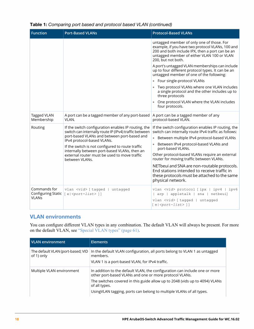
Table 1: Comparing port based and protocol based VLAN (continued)
Protocol-Based VLANsPort-Based VLANsFunction
untagged member of only one of those. Forexample, if you have two protocol VLANs, 100 and200 and both include IPX, then a port can be anuntagged member of either VLAN 100 or VLAN200, but not both.A port's untagged VLANmemberships can includeup to four different protocol types. It can be anuntagged member of one of the following:• Four single-protocol VLANs
• Two protocol VLANs where one VLAN includesa single protocol and the other includes up tothree protocols
• One protocol VLAN where the VLAN includesfour protocols.
A port can be a tagged member of anyprotocol-based VLAN.
A port can be a taggedmember of any port-basedVLAN.
Tagged VLANMembership
If the switch configuration enables IP routing, theswitch can internally route IPv4 traffic as follows:
If the switch configuration enables IP routing, theswitch can internally route IP (IPv4) traffic betweenport-based VLANs and between port-based andIPv4 protocol-based VLANs.
Routing
• Between multiple IPv4 protocol-based VLANs
• Between IPv4 protocol-based VLANs andport-based VLANs.If the switch is not configured to route traffic
internally between port-based VLANs, then anOther protocol-based VLANs require an externalrouter for moving traffic between VLANs.
external router must be used to move trafficbetween VLANs.
NETbeui and SNAare non-routable protocols.End stations intended to receive traffic inthese protocolsmust be attached to the samephysical network.
vlan <vid> protocol [ipx | ipv4 | ipv6| arp | appletalk | sna | netbeui]
vlan <vid> [tagged | untagged[e|<port-list> ]]
Commands forConfiguring StaticVLANs vlan <vid> [tagged | untagged
[e|<port-list> ]]
VLAN environmentsYou can configure different VLAN types in any combination. The default VLAN will always be present. For moreon the default VLAN, see “Special VLAN types” (page 61).
ElementsVLAN environment
In the default VLAN configuration, all ports belong to VLAN 1 as untaggedmembers.
The default VLAN (port-based; VIDof 1) only
VLAN 1 is a port-based VLAN, for IPv4 traffic.
In addition to the default VLAN, the configuration can include one or moreother port-based VLANs and one or more protocol VLANs.
Multiple VLAN environment
The switches covered in this guide allow up to 2048 (vids up to 4094) VLANsof all types.UsingVLAN tagging, ports can belong to multiple VLANs of all types.
18 HPE ArubaOS-Switch Advanced Traffic Management Guide for WC.16.02

ElementsVLAN environment
Enabling routing on the switch enables it to route IPv4 traffic betweenport-based VLANs and between port-based VLANs and IPv4protocol VLANs.Routing other types of traffic between VLANs requires an external routercapable of processing the appropriate protocols.
VLAN operation
General VLAN operation
• A VLAN is composed of multiple ports operating as members of the same subnet or broadcast domain.
• Ports on multiple devices can belong to the same VLAN.
• Traffic moving between ports in the same VLAN is bridged (or switched).
• Traffic moving between different VLANs must be routed.
• A static VLAN is an 802.1Q-compliant VLAN, configured with one or more ports that remain membersregardless of traffic usage.
• A dynamic VLAN is an 802.1Q-compliant VLAN membership that the switch temporarily creates on a port toprovide a link to another port either in the same VLAN on another device.
Types of static VLANs available in the switch
Port-based VLANs
This type of static VLAN creates a specific layer-2 broadcast domain comprised of member ports that bridge IPv4traffic among themselves. Port-Based VLAN traffic is routable on the switches covered in this guide.
Protocol-based VLANs
This type of static VLAN creates a layer-3 broadcast domain for traffic of a particular protocol and is composed ofmember ports that bridge traffic of the specified protocol type among themselves. Some protocol types are routableon the switches covered in this guide; see Table 1 (page 17).
Designated VLANs
The switch uses these static, port-based VLAN types to separate switch management traffic from other networktraffic. While these VLANs are not limited to management traffic, they provide improved security and availability.
Default VLAN:
This port-based VLAN is always present in the switch and, in the default configuration, includes all ports as members.See “VLAN support and the default VLAN” (page 61).
Except for an IP address and subnet, no configuration steps are needed.
Chapter 2 VLANs 19

Example 1: A switch in the default VLAN configuration
In this example, devices connected to these ports are in the same broadcast domain.
Primary VLAN:
The switch uses this port-based VLAN to run certain features and management functions, including DHCP/Bootpresponses for switch management. In the default configuration, the Default VLAN is also the Primary VLAN.However, any port-based, non-default VLAN can be designated the Primary VLAN. See “The primary VLAN”(page 61).
Secure Management VLAN:
This optional, port-based VLAN establishes an isolated network for managing HPE switches that support this feature.Access to this VLAN and to the switch's management functions are available only through ports configured asmembers. See “The primary VLAN” (page 61).
Voice VLANs:
This optional, port-based VLAN type enables separating, prioritizing, and authenticating voice traffic moving throughyour network, avoiding the possibility of broadcast storms affecting VoIP Voice-over-IP) operation. See “Usingvoice VLANs” (page 59).
In amultiple-VLAN environment that includes older switchmodels theremay be problems related to the sameMAC address appearing on different ports and VLANs on the same switch. In such cases, the solution is toimpose cabling and VLAN restrictions. For more on this topic, see “Multiple VLAN considerations” (page 30).
Multiple port-based VLANs
In Example 2 (page 21), routing within the switch is disabled (the default). Thus communication between anyroutable VLANs on the switch must go through the external router. In this case, VLANs W and X can exchangetraffic through the external router, but traffic in VLANs Y and Z is restricted to the respective VLANs.
VLAN 1(the default) is present but not shown. The default VLAN cannot be deleted from the switch, but portsassigned to other VLANs can be removed from the default VLAN. If internal (IP) routing is enabled on the switch,then the external router is not needed for traffic to move between port-based VLANs.
20 HPE ArubaOS-Switch Advanced Traffic Management Guide for WC.16.02
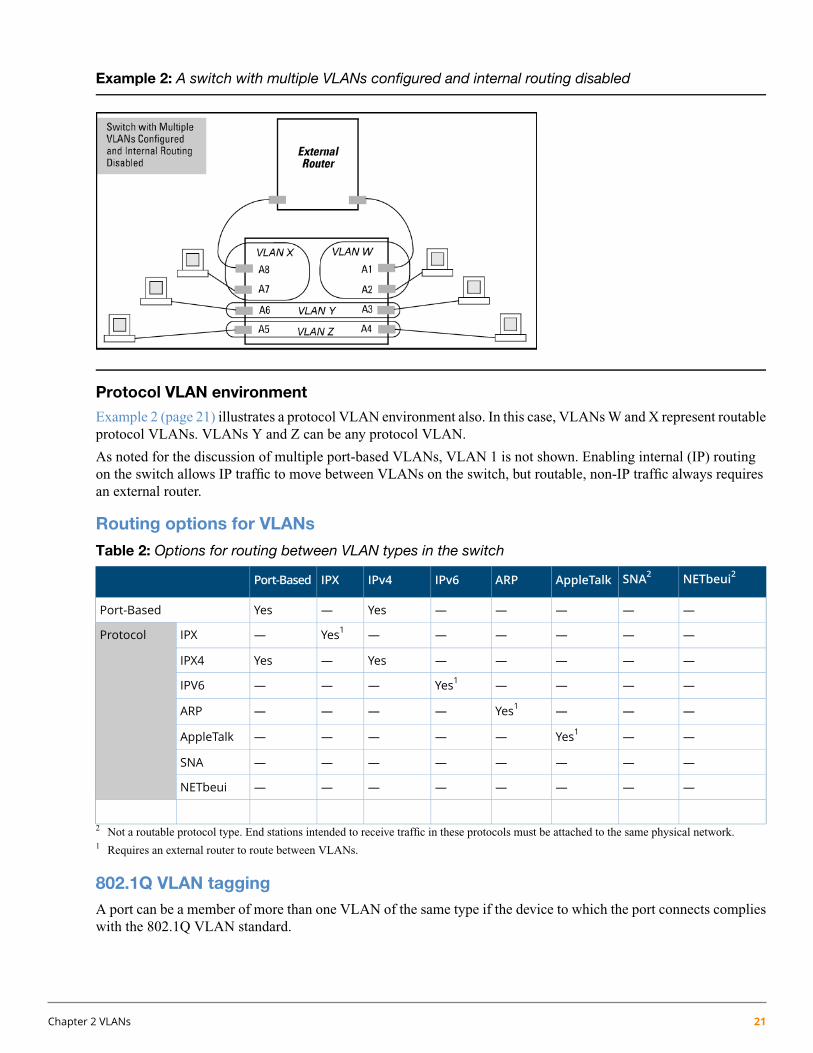
Example 2: A switch with multiple VLANs configured and internal routing disabled
Protocol VLAN environment
Example 2 (page 21) illustrates a protocol VLAN environment also. In this case, VLANs W and X represent routableprotocol VLANs. VLANs Y and Z can be any protocol VLAN.
As noted for the discussion of multiple port-based VLANs, VLAN 1 is not shown. Enabling internal (IP) routingon the switch allows IP traffic to move between VLANs on the switch, but routable, non-IP traffic always requiresan external router.
Routing options for VLANs
Table 2: Options for routing between VLAN types in the switch
NETbeui2SNA2AppleTalkARPIPv6IPv4IPXPort-Based
—————Yes—YesPort-Based
——————Yes1—IPXProtocol
—————Yes—YesIPX4
————Yes1———IPV6
———Yes1————ARP
——Yes1—————AppleTalk
————————SNA
————————NETbeui
2 Not a routable protocol type. End stations intended to receive traffic in these protocols must be attached to the same physical network.1 Requires an external router to route between VLANs.
802.1Q VLAN taggingA port can be a member of more than one VLAN of the same type if the device to which the port connects complieswith the 802.1Q VLAN standard.
Chapter 2 VLANs 21

For example, a port connected to a central server using a network interface card (NIC) that complies with the 802.1Qstandard can be a member of multiple VLANs, allowing members of multiple VLANs to use the server.
• Although these VLANs cannot communicate with each other through the server, they can all access the serverover the same connection from the switch.
• Where VLANs overlap in this way, VLAN "tags" are used in the individual packets to distinguish betweentraffic from different VLANs.
• A VLAN tag includes the particular VLAN I.D. (VID) of the VLAN on which the packet was generated.
For more on this topic, see “Configuring or changing static VLAN per-port settings (CLI)” (page 40).
Example 3: Overlapping VLANs using the same server
Similarly, using 802.1Q-compliant switches, you can connect multiple VLANs through a single switch-to-switchlink.
Example 4: Connecting multiple VLANs through the same link
Introducing tagged VLANs into legacy networks running only untagged VLANs
You can introduce 802.1Q-compliant devices into networks that have built untagged VLANs based on earlier VLANtechnology. The fundamental rule is that legacy/untagged VLANs require a separate link for each VLAN, while802.1Q, or tagged VLANs can combine several VLANs in one link. Thus on the 802.1Q-compliant device, separateports (configured as untagged) must be used to connect separate VLANs to non-802.1Q devices.
22 HPE ArubaOS-Switch Advanced Traffic Management Guide for WC.16.02

Example 5: Tagged and untagged VLAN technology in the same network
VLAN tagging rules
When tagging is needed
When a port belongs to two or more VLANs of the same type, they remain as separate broadcast domains and cannotreceive traffic from each other without routing.
If multiple, non-routable VLANs exist in the switch—such as NETbeui protocol VLANs—they cannot receivetraffic from each other.
Inbound tagged packets
The switch requires VLAN tagging on a given port if the port will be receiving inbound, tagged VLAN traffic thatshould be forwarded. Even if the port belongs to only one VLAN, it forwards inbound tagged traffic only if it is atagged member of that VLAN.
If a tagged packet arrives on a port that is not a tagged member of the VLAN indicated by the packet's VID, theswitch drops the packet.
Similarly, the switch drops an inbound, tagged packet if the receiving port is an untagged member of the VLANindicated by the packet's VID.
Untagged packet forwarding
If the only authorized, inbound VLAN traffic on a port arrives untagged, then the port must be an untagged memberof that VLAN. This is the case where the port is connected to a non-802.1Q compliant device or is assigned to onlyone VLAN.
To enable an inbound port to forward an untagged packet, the port must be an untagged member of either a protocolVLAN matching the packet's protocol, or an untagged member of a port-based VLAN.
That is, when a port receives an incoming, untagged packet, it processes the packet according to the followingordered criteria:
Chapter 2 VLANs 23

1. If the port has no untagged VLAN memberships, the switch drops the packet.2. If the port has an untagged VLAN membership in a protocol VLAN that matches the protocol type of the
incoming packet, then the switch forwards the packet on that VLAN.3. If the port is a member of an untagged, port-based VLAN, the switch forwards the packet to that VLAN.
Otherwise, the switch drops the packet.
24 HPE ArubaOS-Switch Advanced Traffic Management Guide for WC.16.02

Figure 1: Untagged VLAN operation
Is the port an untagged member of any VLANs?
Does the packet’s protocol match the protocol of an untagged protocol VLAN membership on the port?
Is the port a member of an untagged, port‐based
VLAN?
Drop the packet.
Forward the packet on that protocol VLAN.
Drop the packet.
No
No
Yes
Yes
Port “X” receives an inbound, untagged
packet.
Forward the packet on the port‐based VLAN.
No
Yes
Chapter 2 VLANs 25

Tagged packet forwarding
If a port is a tagged member of the same VLAN as an inbound, tagged packet received on that port, then the switchforwards the packet to an outbound port on that VLAN.
To enable the forwarding of tagged packets, any VLAN to which the port belongs as a tagged member must havethe same VID as that carried by the inbound, tagged packets generated on that VLAN.
Figure 2: Tagged VLAN operation
See also “Multiple VLAN considerations” (page 30).
Rate limiting may behave unpredictably on a VLAN if the VLAN spans multiple modules or port-banks.
This also applies if a port on a different module or port-bank is added to an existing VLAN. Hewlett PackardEnterprise does not recommend configuring rate limiting on VLANs that include ports spanning modules orport-banks.
In the following example, ports 2, 3 and 24 form one VLAN, with ports 1 through 24 in the same port-bank. Ports28, 29 and 32 form a second VLAN. These ports are also in the same port-bank, which includes ports 25 through48. Rate limiting will operate as expected for these VLANs.
Figure 3: Example of VLANs using ports from the same port-bank for each VLAN
26 HPE ArubaOS-Switch Advanced Traffic Management Guide for WC.16.02

Applying VLAN tagging
Example of tagged and untagged VLAN port assignments
If port 7 on an 802.1Q-compliant switch is assigned to only the Red VLAN, the assignment can remain "untagged"because the port will forward traffic only for the Red VLAN. However, if both the Red and Green VLANs areassigned to port 7, then at least one of those VLAN assignments must be "tagged" so that Red VLAN traffic can bedistinguished from Green VLAN traffic.
Figure 4: Tagged and untagged VLAN port assignments
In switch X:
• VLANs assigned to ports X1 - X6 can be untagged because there is only one VLAN assignment per port. RedVLAN traffic will go out only the Red ports, Green VLAN traffic will go out only the Green ports, and so on.Devices connected to these ports do not have to be 802.1Q-compliant.
• However, because both the Red VLAN and the Green VLAN are assigned to port X7, at least one of the VLANsmust be tagged for this port.
In switch Y:
• VLANs assigned to ports Y1 - Y4 can be untagged because there is only one VLAN assignment per port.Devices connected to these ports do not have to be 802.1Q-compliant.
• Because both the Red VLAN and the Green VLAN are assigned to port Y5, at least one of the VLANs mustbe tagged for this port.
In both switches:
• The ports on the link between the two switches must be configured the same. As shown in Figure 5, the RedVLAN must be untagged on port X7 and Y5 and the Green VLAN must be tagged on port X7 and Y5, or theopposite way.
Each 802.1Q-compliant VLAN must have its own unique VID number and that VLAN must be given the sameVID in every device where configured. That is, if the Red VLAN has a VID of 10 in switch X, then 10 must alsobe the Red VID in switch Y.
Chapter 2 VLANs 27
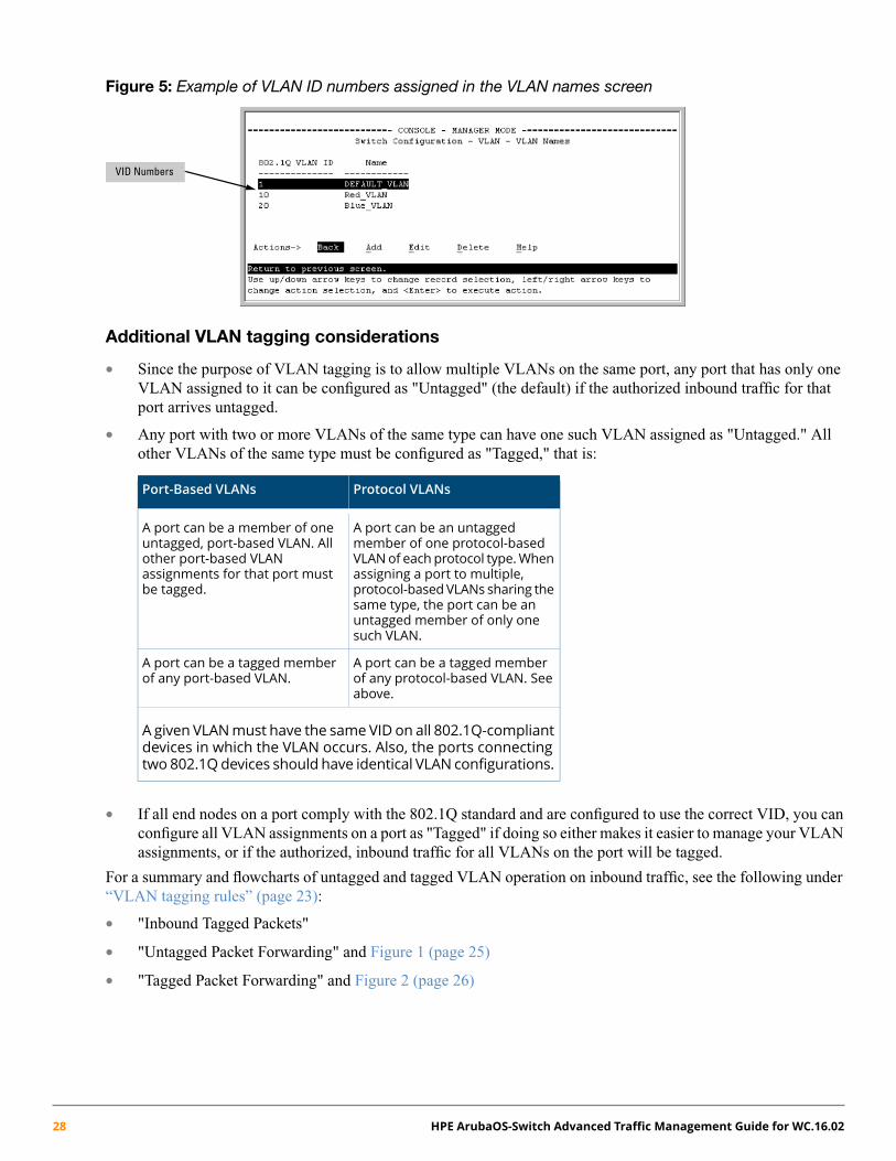
Figure 5: Example of VLAN ID numbers assigned in the VLAN names screen
VID Numbers
Additional VLAN tagging considerations
• Since the purpose of VLAN tagging is to allow multiple VLANs on the same port, any port that has only oneVLAN assigned to it can be configured as "Untagged" (the default) if the authorized inbound traffic for thatport arrives untagged.
• Any port with two or more VLANs of the same type can have one such VLAN assigned as "Untagged." Allother VLANs of the same type must be configured as "Tagged," that is:
Protocol VLANsPort-Based VLANs
A port can be an untaggedmember of one protocol-based
A port can be a member of oneuntagged, port-based VLAN. All
VLANof each protocol type.Whenother port-based VLANassigning a port to multiple,assignments for that port must
be tagged. protocol-basedVLANs sharing thesame type, the port can be anuntagged member of only onesuch VLAN.
A port can be a tagged memberof any protocol-based VLAN. Seeabove.
A port can be a tagged memberof any port-based VLAN.
A given VLANmust have the same VID on all 802.1Q-compliantdevices in which the VLAN occurs. Also, the ports connectingtwo 802.1Qdevices should have identical VLAN configurations.
• If all end nodes on a port comply with the 802.1Q standard and are configured to use the correct VID, you canconfigure all VLAN assignments on a port as "Tagged" if doing so either makes it easier to manage your VLANassignments, or if the authorized, inbound traffic for all VLANs on the port will be tagged.
For a summary and flowcharts of untagged and tagged VLAN operation on inbound traffic, see the following under“VLAN tagging rules” (page 23):
• "Inbound Tagged Packets"
• "Untagged Packet Forwarding" and Figure 1 (page 25)
• "Tagged Packet Forwarding" and Figure 2 (page 26)
28 HPE ArubaOS-Switch Advanced Traffic Management Guide for WC.16.02

Example of Networked 802.1Q-compliant devices with multiple VLANs on some ports
In the following network, switches X and Y and servers S1, S2, and the AppleTalk server are 802.1Q-compliant.(Server S3 could also be 802.1Q-compliant, but it makes no difference for this example.) This network includesboth protocol-based (AppleTalk) VLANs and port-based VLANs.
AppleTalk Server
Switch “X”
X1 X2
X3
X6 X5
Green VLAN
System Server S2
Switch“Y” Y6
Y1
Apple Talk
VLAN 1
System Server S1
X4
RedVLAN
Y5 Y4
Apple Talk
VLAN 2
Y3
Green VLAN
RedVLAN
SystemServer S3Y2
Red VLAN: Untagged Green VLAN: Tagged AT2 (Protocol) VLAN: Untagged
Red VLAN: Untagged Green VLAN: Tagged
Green VLAN Only
AT1 (Protocol) VLAN: Untagged
• The VLANs assigned to ports X4 - X6 and Y2 - Y5 can all be untagged because there is only one VLANassigned per port.
• Port X1 has two AppleTalk VLANs assigned, which means that one VLAN assigned to this port can be untaggedand the other must be tagged.
• Ports X2 and Y1 have two port-based VLANs assigned, so one can be untagged and the other must be taggedon both ports.
• Ports X3 and Y6 have two port-based VLANs and one protocol-based VLAN assigned. Thus, one port-basedVLAN assigned to this port can be untagged and the other must be tagged. Also, since these two ports sharethe same link, their VLAN configurations must match.
Switch YSwitch X
GreenVLAN
Red VLANAT-2 VLANAT-1 VLANPortGreenVLAN
Red VLANAT-2 VLANAT-1 VLANPort
TaggedUntaggedNo*No*Y1No*No*TaggedUntaggedX1
UntaggedNo*No*No*Y2TaggedUntaggedNo*No*X2
No*No*UntaggedNo*Y3TaggedUntaggedUntaggedNo*X3
UntaggedNo*No*No*Y4UntaggedNo*No*No*X4
No*UntaggedNo*No*Y5No*UntaggedNo*No*X5
TaggedUntaggedUntaggedNoY6No*No*No*UntaggedX6
Chapter 2 VLANs 29

* No means that the port is not a member of that VLAN. For example, port X3 is not a member of the Red VLAN and does not carry Red VLAN traffic.
Also, if GVRP were enabled (port-based only), Auto would appear instead of No.
VLAN configurations onports connected by the same link must match. Because ports X2 and Y5 are oppositeends of the same point-to-point connection, both ports must have the same VLAN configuration, configuringthe Red VLAN as "Untagged" and the Green VLAN as "Tagged.”
Multiple VLAN considerationsSwitches use a forwarding database to maintain awareness of which external devices are located on which VLANs.Some switches, such as the switches covered in this guide, have a multiple forwarding database, which means theswitch allows multiple database entries of the same MAC address, with each entry showing the (different) sourceVLAN and source port. Other switch models have a single forwarding database, which allows only one databaseentry of a unique MAC address, along with the source VLAN and source port on which it is found. All VLANs ona switch use the same MAC address. Thus, connecting a multiple forwarding database switch to a single forwardingdatabase switch where multiple VLANs exist imposes some cabling and port VLAN assignment restrictions. Thefollowing table illustrates the functional difference between the two database types.
Table 3: Forwarding database content
Single forwarding databaseMultiple forwarding database
Destination portDestination VLANID
MAC addressDestination portDestination VLANID
MAC address
A91000004ea-84d9f4A510004ea-84d9f4
A101050060b0-880af9A12220004ea-84d9f4
A171070060b0-880a81A20440004ea-84d9f4
A20330060b0-880a81
This database allows only one destination for aMACaddress.This database allowsmultiple destinations for the sameMACaddress. If the switch detects a new destination for an existing MAC
entry, it replaces the existing MAC instance with a newinstance showing the new destination.
If the switch detects a new destination for an existing MACentry, it just adds a new instance of that MAC to the table.
Table 4: Forwarding database structure for managed switches
Single forwarding database*Multiple forwarding databases*
Series 2500 switchesSeries 6400cl switches
Switch 800TSwitch 6108
Series 5400zl switches
Series 5300xl switches
Series 4200vl switches
Series 4100gl switches
Series 3500 switches
Series 3500yl switches
Series 3400cl switches
30 HPE ArubaOS-Switch Advanced Traffic Management Guide for WC.16.02

Table 4: Forwarding database structure for managed switches (continued)
Single forwarding database*Multiple forwarding databases*
Switch 2810
Series E2800 switches
Series 2600/2600-PWR switches
Series 2510 switches
*To determine whether other vendors' devices use single-forwarding or multiple-forwarding database architectures, seethe documentation provided for those devices.
Single forwarding database operation
When a packet arrives with a destination MAC address that matches a MAC address in the switch's forwarding table,the switch tries to send the packet to the port listed for that MAC address. But if the destination port is in a differentVLAN than the VLAN on which the packet was received, the switch drops the packet. This is not a problem for aswitch with a multiple forwarding database because the switch allows multiple instances of a given MAC address,one for each valid destination. However, a switch with a single forwarding database allows only one instance of agiven MAC address.
If you (1) connect both switch types through multiple ports or trunks belonging to different VLANs and (2)enable routing on the switchwith themultiple-forwarding database, then the port and VLAN recordmaintainedon the switchwith the single-forwarding database for themultiple-forwarding database can change frequently.This may cause poor performance and the appearance of an intermittent or broken connection.
Switch performance is unreliable
The following example provides a method to identify and correct an unsupported configuration.
Symptom
Poor switch performance, unreliable switch performance, dropped packets, discarded packets, appearance ofintermittent or broken links.
Cause
Incorrect switch configuration.
As shown in Figure 6 (page 32), two switches are connected using two ports on each, and the MAC address tablefor Switch 8000M will sometimes record the switch as accessed on port A1 (VLAN 1) and at other times as accessedon port B1 (VLAN 2).
1. PC A sends an IP packet to PC B.2. The packet enters VLAN 1 in the switch with the MAC address of the switch in the destination field. Because
the switch has not yet learned this MAC address, it does not find the address in its address table and floods thepacket out all ports, including the VLAN 1 link (port A1) to the switch. The switch then routes the packetthrough the VLAN 2 link to the switch, which forwards the packet on to PC B. Because the switch receivedthe packet from the switch on VLAN 2 (port B1), the switch's single forwarding database records the switchas being on port B1 (VLAN 2).
3. PC A now sends a second packet to PC B. The packet again enters VLAN 1 in the switch with the MAC addressof the switch in the destination field. However, this time the switch's single forwarding database indicates thatthe switch is on port B1 (VLAN 2) and the switch drops the packet instead of forwarding it.
Chapter 2 VLANs 31

4. Later, the switch transmits a packet to the switch through the VLAN 1 link and the switch updates its addresstable to show that the switch is on port A1 (VLAN 1) instead of port B1 (VLAN 2). Thus, the switch's informationon the location of the switch changes over time, and the switch discards some packets directed through it forthe switch. This causes poor performance and the appearance of an intermittent or broken link.
Figure 6: Invalid forwarding configuration
Action/solution
Reconfigure the switches in the configuration.
1. Use only one cable or port trunk between single-forwarding and multiple-forwarding database devices.2. Configure the link with multiple, tagged VLANs.3. To increase network bandwidth of the connection between devices, use a trunk of multiple physical links.
Following these rules, the switch forwarding database always lists the switch MAC address on port A1 and theswitch will send traffic to either VLAN on the switch.
Figure 7: Solution for single-forwarding to multiple-forwarding database devices in a multiple VLANenvironment
Connecting the Switch to another switch with a multiple forwarding database (Example)
Use one or both of the following connection options:
• A separate port or port trunk interface for each VLAN. This results in a forwarding database having multipleinstances of the same MAC address with different VLAN IDs and port numbers. See Table 3 (page 30). Thefact that the switches covered by this guide use the same MAC address on all VLAN interfaces causes noproblems.
• The same port or port trunk interface for multiple (tagged) VLANs. This results in a forwarding database havingmultiple instances of the same MAC address with different VLAN IDs, but the same port number.
32 HPE ArubaOS-Switch Advanced Traffic Management Guide for WC.16.02

Allowing multiple entries of the same MAC address on different VLANs enables topologies such as the following:
Figure 8: Topology for devices with multiple forwarding databases in a multiple VLAN environment
4108gl Switch
VLAN 1 VLAN 2
8212zl Switch
VLAN 1 VLAN 2 Both switches have multiple forwarding databases.
Configuring VLANsThe Menu interface enables configuration and display of port-based VLANs only. The CLI configures and displaysport-based and protocol-based VLANs.
In the factory default state, the switch is enabled for up to 256 VLANs, all ports belong to the default primary VLANand are in the same broadcast/multicast domain. You can reconfigure the switch to support up to 2048 VLANs, withup to 4094 VIDs, by adding new VLAN names and VIDs and then assigning one or more ports to each VLAN.
Per-port static VLAN configuration options exampleThis example shows the options available to assign individual ports to a static VLAN.
GVRP, if configured, affects these options and the VLAN behavior on the switch.
Figure 9: Comparing per-port VLAN options with and without GVRP
Chapter 2 VLANs 33

Table 5: Per-port VLAN configuration options
Effect on port participation in designated VLANParameter
Allows the port to join multiple VLANs.Tagged
Untagged • Allows VLAN connection to a device that is configured for an untagged VLAN insteadof a tagged VLAN.
• A port can be an untagged member of only one port-based VLAN.
• A port can be an untaggedmember of only one protocol-based VLAN for any givenprotocol type.
For example, if the switch is configuredwith the default VLANplus three protocol-basedVLANs that include IPX, then port 1 can be an untagged member of the default VLANand one of the protocol-based VLANS.
No:
When the switch is not GVRP-enabled; prevents the port from joining that VLAN.Auto:When GVRP is enabled on the switch; it allows the port to dynamically join anyadvertised VLAN that has the same VID.
No or Auto
Prevents the port from joining the VLAN, even if GVRP is enabled on the switch.Forbid
Using the Menu to configure port-based VLAN parameters
TheMenu interface configures and displays only port-based VLANs. The CLI configures and displays port-basedand protocol-based VLANs (see “Using the CLI to configure port-based and protocol-based VLAN parameters”(page 38).
In the factory default state, support is enabled for up to 256 VLANs. (You can reconfigure the switch to support upto 2048 (vids up to 4094) VLANs.) Also, in the default configuration, all ports on the switch belong to the defaultVLAN and are in the same broadcast/multicast domain. (The default VLAN is also the default Primary VLAN; see“The primary VLAN” (page 61).) In addition to the default VLAN, you can configure additional static VLANs byadding new VLAN names and VIDs, and then assigning one or more ports to each VLAN. (The maximum of 2048VLANs includes the default VLAN, all additional static VLANs you configure, and any dynamic VLANs the switchcreates if you enable GVRP; see “GVRP” (page 75).) Each port can be assigned to multiple VLANs by using VLANtagging; see “VLAN tagging rules” (page 23).)
Changing VLAN support settings (Menu)
The following procedure provides instructions for changing the maximum number of VLANs to support, changingthe primary VLAN selection and enabling or disabling dynamic VLANs.
34 HPE ArubaOS-Switch Advanced Traffic Management Guide for WC.16.02

1. From the Main Menu select: 2. Switch Configuration —> 8. VLAN Menu … —> 1. VLAN Support
You see the following screen:
Figure 10: The default VLAN support screen
2. Press E (for Edit) and then do one or more of the following:
• To change the maximum number of VLANs, enter the new number (1 - 2048 allowed; default 256).
• To designate a different VLAN as the Primary VLAN, select the Primary VLAN field and use the spacebar to select from the existing options. The Primary VLAN must be a static, port-based VLAN.
• To enable or disable dynamic VLAgNs, select the GVRP Enabled field and use the Space bar to togglebetween options. For GVRP information, see “GVRP” (page 75).
For optimal switch memory utilization, set the number of VLANs at the number you will likely be using ora few more. If you need more VLANs later, you can increase this number, but a switch reboot will berequired at that time.
3. Press Enter and then S to save the VLAN support configuration and return to the VLAN Menu screen.
If you changed the value for Maximum VLANs to support, an asterisk appears next to the VLAN Supportoption; see Figure 11 (page 35).
Figure 11: VLAN menu screen indicating the need to reboot the switch
• If you changed the VLAN Support option, you must reboot the switch before the maximum VLANs changetakes effect. You can go on to configure other VLAN parameters first, but you must reboot the switchwhen you finish.
• If you did not change the VLAN Support option, a reboot is not necessary.
Chapter 2 VLANs 35
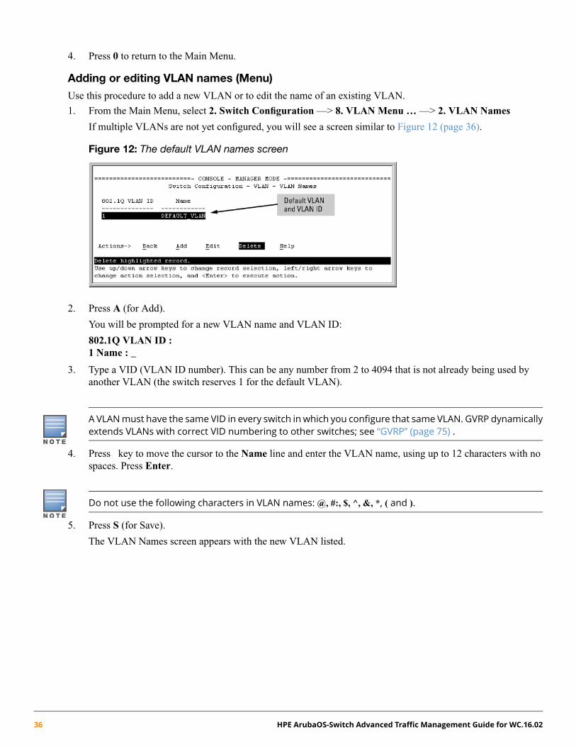
4. Press 0 to return to the Main Menu.
Adding or editing VLAN names (Menu)
Use this procedure to add a new VLAN or to edit the name of an existing VLAN.
1. From the Main Menu, select 2. Switch Configuration —> 8. VLAN Menu … —> 2. VLAN Names
If multiple VLANs are not yet configured, you will see a screen similar to Figure 12 (page 36).
Figure 12: The default VLAN names screen
2. Press A (for Add).
You will be prompted for a new VLAN name and VLAN ID:
802.1Q VLAN ID :1 Name : _
3. Type a VID (VLAN ID number). This can be any number from 2 to 4094 that is not already being used byanother VLAN (the switch reserves 1 for the default VLAN).
A VLANmust have the same VID in every switch in which you configure that same VLAN. GVRP dynamicallyextends VLANs with correct VID numbering to other switches; see “GVRP” (page 75) .
4. Press key to move the cursor to the Name line and enter the VLAN name, using up to 12 characters with nospaces. Press Enter.
Do not use the following characters in VLAN names: @, #:, $, ^, &, *, ( and ).
5. Press S (for Save).
The VLAN Names screen appears with the new VLAN listed.
36 HPE ArubaOS-Switch Advanced Traffic Management Guide for WC.16.02

Figure 13: VLAN Names screen with a new VLAN added
6. Repeat steps 2 through 5 to add more VLANs.
You can add VLANs until you reach the number specified in the Maximum VLANs to support field on theVLAN Support screen. This includes any VLANs added dynamically due toGVRP operation.
Return to the VLAN Menu to assign ports to the new VLAN, as described in “Adding or changing a VLAN portassignment (Menu)” (page 37).
Adding or changing a VLAN port assignment (Menu)
Ports not specifically assigned to a VLAN are automatically in the default VLAN.
1. From the Main Menu select: 2. Switch Configuration —> 8. VLAN Menu … —> 3. VLAN Port Assignment
You will see a screen similar to the following:
Figure 14: Port-based VLAN port assignment screen in the menu interface
The "VLAN Port Assignment" screen displays up to 32 static, port-based VLANs in ascending order, by VID.If the switch configuration includes more than 32 such VLANs, use the following CLI command to list dataon VLANs having VIDs numbered sequentially higher than the first 32.show vlans [ <vid> | ports [ <port-list> ]]
2. To change a port's VLAN assignment:a. Press E (for Edit).b. Use the arrow keys to select a VLAN assignment you want to change.
Chapter 2 VLANs 37

c. Press the Space bar to make your assignment selection (No, Tagged, Untagged , or Forbid. For informationon VLAN tags, see “802.1Q VLAN tagging” (page 21).
d. If you are finished assigning ports to VLANs, press Enter and then S (for Save) to activate the changesand return to the Configuration menu. (The console then returns to the VLAN menu.)
3. Return to the Main menu.
For GVRP Operation: If you enable GVRP on the switch, No converts to Auto, which allows the VLAN todynamically join an advertised VLAN that has the same VID.Untagged VLANs Only one untagged VLAN is allowed per port. Also, there must be at least one VLAN
assigned to each port. In the factory default configuration, all ports are assigned tothe default VLAN (DEFAULT_VLAN).
For ports A4 and A5 to belong to both DEFAULT_VLAN and VLAN-22 and ports A6 and A7 to belong only toVLAN-22, use the settings in “The default VLAN names screen” (page 36). This example assumes that the defaultGVRP setting is disabled and that you do not plan to enable GVRP later.
Example 6: Displaying port-based VLAN assignments for specific ports
Using the CLI to configure port-based and protocol-based VLAN parametersIn the factory default state, all ports on the switch belong to the port-based default VLAN (DEFAULT_VLAN;VID=1) and are in the same broadcast/multicast domain.
The default VLAN is also the Primary VLAN. For more on this topic, see “The primary VLAN” (page 61).)
You can configure up to 255 additional static VLANs by adding new VLAN names and then assigning one or moreports to each VLAN.
The switch accepts a maximum of 2048 VLANs with VIDs numbered up to 4094. This must include the defaultVLAN and any dynamic VLANs the switch creates if you enable GVRP (see “GVRP” (page 75)).
Each port can be assigned to multiple VLANs by using VLAN tagging. See “VLAN tagging rules” (page 23).
Creating a new static VLAN (port-based or protocol-based) (CLI)
The vlan <vid> command operates in the global configuration context to configure a static VLAN and/or takethe CLI to a specified VLAN's context.
38 HPE ArubaOS-Switch Advanced Traffic Management Guide for WC.16.02

Syntax:
vlan vid | <ascii-name-string>[no] vlan <vid>
If <vid> does not exist in the switch, this command creates a port-based VLAN with the specified<vid>
If the command does not include options, the CLI, moves to the newly created VLAN context.
If an optional name is not specified, the switch assigns a name in the default format VLAN n, wheren is the <vid> assigned to the VLAN.
If the VLAN exists and you enter either the <vid> or the <ascii-name-string>,the CLImoves to the specified VLAN's context.
The no form of the command deletes the VLAN as follows:
If one or more ports belong only to the VLAN to be deleted, the CLI notifies you that these portswill be moved to the default VLAN and prompts you to continue the deletion. For member portsthat also belong to another VLAN, there is no move prompt.
protocol [ ipx|ipv4|ipv6|arp|appletalk|sna|netbeui ]Configures a static, protocol VLAN of the specified type.
If multiple protocols are configured in the VLAN, the no form removes the specified protocol
If a protocol VLAN is configured with only one protocol type and you use the no form of thiscommand to remove that protocol, the switch changes the protocol VLAN to a port-based VLAN(if the VLAN does not have an untagged member port).
If an untagged member port exists on the protocol VLAN, you must either convert the port to atagged member or remove the port from the VLAN before removing the last protocol type from theVLAN.
If you create an IPv4 protocol VLAN, you must assign the ARP protocol option to it to provideIP address resolution. Otherwise, IP packets are not deliverable. A Caution message appearsin the CLI if you configure IPv4 in a protocol VLAN that does not already include the ARP protocoloption. The same message appears if you add or delete another protocol in the same VLAN.
name <ascii-name-string>When included in a vlan command to create a new static VLAN, this command specifies anon-default VLAN name. Also used to change the current name of an existing VLAN.
Avoid spaces and the following characters in the <ascii-name-string> entry: @, #:, $, ^, &,*, ( and). To include a blank space in a VLAN name, enclose the name in single or doublequotes.
voice
Designates a VLAN for VoIP use. For more on this topic, see “Using voice VLANs” (page 59).
You can use these options from the configuration level by beginning the command with vlan<vid>, or from the context level of the specific VLAN by just entering the command option.
Chapter 2 VLANs 39
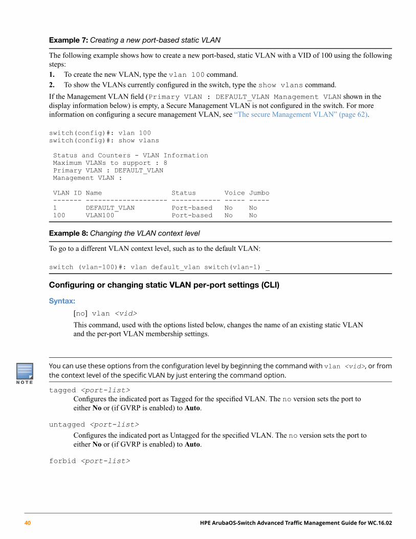
Example 7: Creating a new port-based static VLAN
The following example shows how to create a new port-based, static VLAN with a VID of 100 using the followingsteps:1. To create the new VLAN, type the vlan 100 command.2. To show the VLANs currently configured in the switch, type the show vlans command.
If the Management VLAN field (Primary VLAN : DEFAULT_VLAN Management VLAN shown in thedisplay information below) is empty, a Secure Management VLAN is not configured in the switch. For moreinformation on configuring a secure management VLAN, see “The secure Management VLAN” (page 62).
switch(config)#: vlan 100switch(config)#: show vlans
Status and Counters - VLAN InformationMaximum VLANs to support : 8Primary VLAN : DEFAULT_VLANManagement VLAN :
VLAN ID Name Status Voice Jumbo------- -------------------- ------------ ----- -----1 DEFAULT_VLAN Port-based No No100 VLAN100 Port-based No No
Example 8: Changing the VLAN context level
To go to a different VLAN context level, such as to the default VLAN:
switch (vlan-100)#: vlan default_vlan switch(vlan-1) _
Configuring or changing static VLAN per-port settings (CLI)
Syntax:
[no] vlan <vid>
This command, used with the options listed below, changes the name of an existing static VLANand the per-port VLAN membership settings.
You can use these options from the configuration level by beginning the command with vlan <vid>, or fromthe context level of the specific VLAN by just entering the command option.
tagged <port-list>Configures the indicated port as Tagged for the specified VLAN. The no version sets the port toeither No or (if GVRP is enabled) to Auto.
untagged <port-list>
Configures the indicated port as Untagged for the specified VLAN. The no version sets the port toeither No or (if GVRP is enabled) to Auto.
forbid <port-list>
40 HPE ArubaOS-Switch Advanced Traffic Management Guide for WC.16.02

Used in port-based VLANs, configures <port-list> as forbidden, to become a member of thespecified VLAN, as well as other actions. Does not operate with option not allowed protocol VLANs.The no version sets the port to either No or (if GVRP is enabled) to Auto. See “GVRP” (page 75).
auto <port-list>
Available if GVRP is enabled on the switch. Returns the per-port settings for the specified VLANto Auto operation. Auto is the default per-port setting for a static VLAN if GVRP is running onthe switch. For information on dynamic VLAN and GVRP operation, see “GVRP” (page 75).
Example 9: Changing the VLAN name and set ports to tagged
Suppose that there is a VLAN named VLAN100 with a VID of 100 and all ports are set to No for this VLAN. Tochange the VLAN name to Blue_Team and set ports A1 - A5 to Tagged, use the following commands:
switch(config)#: vlan 100 name Blue_Teamswitch(config)#: vlan 100 tagged a1-a5
Example 10: Moving the context level
To move to the vlan 100 context level and execute the same commands:
switch(config)#: vlan 100switch(vlan-100)#: name Blue_Teamswitch(vlan-100)#: tagged a1-a5
Example 11: Changing tagged ports
Similarly, to change the tagged ports in the above examples to No (or Auto, if GVRP is enabled), use either of thefollowing commands.
At the global config level, use:
switch(config)#: no vlan 100 tagged a1-a5
- or -
At the VLAN 100 context level, use:
switch(vlan-100)#: no tagged a1-a5
You cannot use these commands with dynamic VLANs. Attempting to do so displays the message VLANalready exists with no change.
Converting a dynamic VLAN to a static VLAN (CLI)
Syntax:
static-vlan <vlan-id>
Converts a dynamic, port-based VLAN membership to static, port-based VLAN membership (allowsport-based VLANs only).
For this command,<vlan-id> refers to the VID of the dynamic VLAN membership. Use showvlan to help identify the VID.
Chapter 2 VLANs 41

This command requires that GVRP is running on the switch and a port is currently a dynamicmember of the selected VLAN.
After you convert a dynamic VLAN to static, you must configure the switch's per-port participationin the VLAN in the same way that you would for any static VLAN. For GVRP and dynamic VLANoperation, see “GVRP” (page 75).
Example 12: Converting a dynamic VLAN to a port-based static VLAN
Suppose a dynamic VLAN with a VID of 125 exists on the switch. The following command converts the VLAN toa port-based, static VLAN:
HP(config)#: static-vlan 125
Deleting a static VLAN (CLI)
Syntax:
no vlan <vid>
Before deleting a static VLAN, reassign all ports in the VLAN to another VLAN.
Example 13: Deleting a static VLAN
Following Figure 13 (page 37), if ports B1-B5 belong to both VLAN 2 and VLAN 3 and ports B6-B10 belong toVLAN 3, deleting VLAN 3 causes the CLI to prompt you to approve moving ports B6 - B10 to VLAN 1 (the defaultVLAN). (Ports B1-B5 are not moved because they still belong to another VLAN.)
switch(config)#: no vlan 3The following ports will be moved to the default VLAN:B6-B10Do you want to continue?[y/n] Yswitch(config)#::
Deleting multiple VLANs
Enables the user to add or delete interfaces from multiple tagged or untagged VLANs or SVLANs using a singlecommand. Interfaces can be added or deleted up to 256 VLANs at a time. If more than 256 VLANs are specified,an error displays. The forbid command option prevents specified ports from becoming members of specifiedVLANs or SVLANs when used with GVRP. The command is executed in the interface context.
42 HPE ArubaOS-Switch Advanced Traffic Management Guide for WC.16.02

Syntax
[no]interface <port-list> <tagged | untagged | forbid> <vlan | svlan<vlan-id-list>>
• The specified interfaces are added to existing VLANs or SVLANs. If a VLAN or SVLAN doesnot exist, an error message displays.
• The [no] option removes the specified interfaces from the specified VLANs or SVLANs.
• The forbid option prevents an interface from becoming a member of the specified VLANs orSVLANs. It is executed in interface context.
Example 14: Removing an interface from several VLANs
The vlan-id-list includes a comma-separated list of VLAN IDs and/or VLAN ID ranges.
Example 15: To remove interface 1 from VLANs 1, 3, 5, 6, 7, 8, 9, 10
switch(config)#: no interface 1,6,7-10 tagged vlan 1,3,5-10
Example 16: To specify that an interface cannot become a member of VLANs 4 and 5
switch(config)#: interface 2 forbid vlan 4-5
Using IP enable/disable for all VLANsYou can administratively disable the IP address on specified VLANs with static IP addresses without removing theLayer 3 configuration. The switch can be pre-configured as a backup router, then quickly transition from backup toactive by re-enabling Layer 3 routing on one or more VLANs. While the switch is in “backup” mode, it will still beperforming Layer 2 switching.
A MIB object will be toggled to make Layer 3 routing active or inactive on a VLAN.
Interaction with other features
This feature affects management access to the switch as follows:
• IP—SNMP, Telnet, SSH, HTTP, TFTP, SCP, SFTP
• Routing—RIP, OSPF, PIM, VRRP
When the disable layer3 command is configured on a VLAN, the behavior is as if no IP address wereconfigured for that VLAN. There is no other change in behavior.
Syntax:
[no] disable layer3 vlan <vid> <vid range>
In config context, turns off Layer 3 routing for the specified VLAN or VLANs. When executed invlan context, turns off Layer 3 routing for that VLAN.
The no form turns on Layer 3 routing for the specified VLAN or VLANs.
The show ip command displays disabled in the IP Config column if Layer 3 has been disabled, or if theVLAN has no IP configuration. You can tell which is the case by viewing the remaining columns; if there is no IPconfiguration, the remaining columns are blank.
Chapter 2 VLANs 43
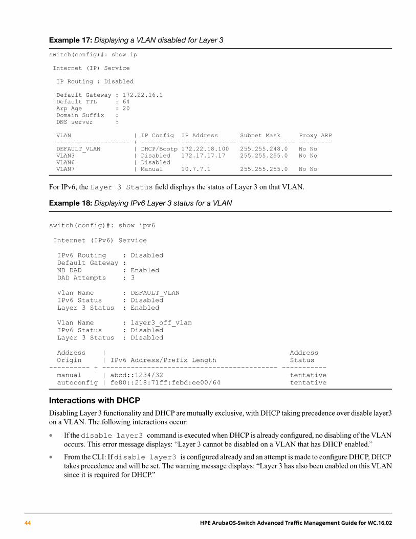
Example 17: Displaying a VLAN disabled for Layer 3
switch(config)#: show ip
Internet (IP) Service
IP Routing : Disabled
Default Gateway : 172.22.16.1Default TTL : 64Arp Age : 20Domain Suffix :DNS server :
VLAN | IP Config IP Address Subnet Mask Proxy ARP-------------------- + ---------- --------------- --------------- ---------DEFAULT_VLAN | DHCP/Bootp 172.22.18.100 255.255.248.0 No NoVLAN3 | Disabled 172.17.17.17 255.255.255.0 No NoVLAN6 | DisabledVLAN7 | Manual 10.7.7.1 255.255.255.0 No No
For IPv6, the Layer 3 Status field displays the status of Layer 3 on that VLAN.
Example 18: Displaying IPv6 Layer 3 status for a VLAN
switch(config)#: show ipv6
Internet (IPv6) Service
IPv6 Routing : DisabledDefault Gateway :ND DAD : EnabledDAD Attempts : 3
Vlan Name : DEFAULT_VLANIPv6 Status : DisabledLayer 3 Status : Enabled
Vlan Name : layer3_off_vlanIPv6 Status : DisabledLayer 3 Status : Disabled
Address | AddressOrigin | IPv6 Address/Prefix Length Status
---------- + ------------------------------------------- -----------manual | abcd::1234/32 tentativeautoconfig | fe80::218:71ff:febd:ee00/64 tentative
Interactions with DHCP
Disabling Layer 3 functionality and DHCP are mutually exclusive, with DHCP taking precedence over disable layer3on a VLAN. The following interactions occur:
• If the disable layer3 command is executed when DHCP is already configured, no disabling of the VLANoccurs. This error message displays: “Layer 3 cannot be disabled on a VLAN that has DHCP enabled.”
• From the CLI: If disable layer3 is configured already and an attempt is made to configure DHCP, DHCPtakes precedence and will be set. The warning message displays: “Layer 3 has also been enabled on this VLANsince it is required for DHCP.”
44 HPE ArubaOS-Switch Advanced Traffic Management Guide for WC.16.02

• From the CLI: When disabling a range of VLAN IDs, this warning message displays: “Layer 3 will not bedisabled for any LANs that have DHCP enabled.”
• From SNMP: If the disable layer3 command is executed when DHCP is already configured, no disablingof the VLAN occurs. An INCONSISTENT_VALUE error is returned.
• From SNMP: If disable layer3 is configured already and an attempt is made to configure DHCP, DHCPtakes precedence and will be set.
Changing the Primary VLAN (CLI)For more information on Primary VLANs, see “The primary VLAN” (page 61).
Syntax:
1. To change the Primary VLAN (CLI), use the following command:primary-vlan vid <ascii-name-string>
In the default VLAN configuration, the port-based default VLAN (DEFAULT_VLAN) is the Primary VLAN.This command reassigns the Primary VLAN function to an existing, port-based, static VLAN.
The switch cannot reassign the Primary VLAN function to a protocol VLAN.
2. If you reassign the Primary VLAN to a non-default VLAN, to delete the Primary VLAN from the switch, youmust assign the Primary VLAN to another port-based static VLAN.
To identify the current Primary VLAN and list the available VLANs and their respective VIDs, useshow vlans.
Example 19: Reassigning, renaming and displaying the VLAN command sequence
The following example shows how to reassign the Primary VLAN to VLAN 22 (first command line), rename theVLAN 22-Primary (second command line) and then display the result (third command line):
switch(config)#: primary-vlan 22switch(config)#: vlan 22 name 22-Primaryswitch(config)#: show vlans
Status and Counters - VLAN InformationMaximum VLANs to support : 8Primary VLAN : 22-PrimaryManagement VLAN :
VLAN ID Name Status Voice Jumbo------- -------------------- ------------ ----- -----1 DEFAULT_VLAN Static No No22 22-Primary Static No No
Configuring a secure Management VLAN (CLI)
Preparation
1. Determine a VID and VLAN name suitable for your Management VLAN.2. Plan your topology to use switches that support Management VLANs. See “The secure Management VLAN”
(page 62).
Chapter 2 VLANs 45

3. Include only the following ports:
• Ports to which you will connect authorized management stations, such as Port A7 in Example 40 (page 62).
• Ports on one switch that you will use to extend the Management VLAN to ports on other switches, suchas ports A1 and Example 40 (page 62).
4. Half-duplex repeaters dedicated to connecting management stations to the Management VLAN can also beincluded in this topology. Any device connected to a half-duplex repeater in the Management VLAN will alsohave Management VLAN access.
5. Configure the Management VLAN on the selected switch ports.6. Test the Management VLAN from all of the management stations authorized to use it, including any SNMP-based
network management stations. Also test any Management VLAN links between switches.
If you configure a Management VLAN on a switch using a Telnet connection through a port not in theManagement VLAN, you will lose management contact with the switch if you log off your Telnet connection orexecute write memory and reboot the switch.
Configuring an existing VLAN as the Management VLAN (CLI)
Syntax:
[no] management-vlan [ <vlan-id> | <vlan-name> ]
Configures an existing VLAN as the Management VLAN.
The no form disables the Management VLAN and returns the switch to its default managementoperation.
Default: Disabled. In this case, the VLAN returns to standard VLAN operation.
46 HPE ArubaOS-Switch Advanced Traffic Management Guide for WC.16.02

Example 20: Switch configuration
You have configured a VLAN named My_VLAN with a VID of 100 and want to configure the switch to do thefollowing:
• Use My_VLAN as a Management VLAN (tagged, in this case) to connect port A1 on switch "A" to a managementstation. The management station includes a network interface card with 802.1Q tagged VLAN capability.
• Use port A2 to extend the Management VLAN to port B1 which is already configured as a tagged member ofMy_VLAN, on an adjacent switch that supports the Management VLAN feature.
switch (config)#: management-vlan 100switch (config)#: vlan 100 tagged a1switch (config)#: vlan 100 tagged a2
Example 21: Configuration Example
Obtaining an IP address using DHCP (CLI)
Use DHCP to obtain an IPv4 address for your Management VLAN or a client on that VLAN. The following examplesillustrate when an IP address will be received from the DHCP server.
Chapter 2 VLANs 47

Example 22: DHCP server on a Management VLAN
If Blue_VLAN is configured as the Management VLAN and the DHCP server is also on Blue_VLAN, Blue_VLANreceives an IP address. Because DHCP Relay does not forward onto or off the Management VLAN, devices onRed_VLAN cannot get an IP address from the DHCP server on Blue_VLAN (Management VLAN) and Red_VLANdoes not receive an IP address.
Example 23: DHCP server on a different VLAN from the Management VLAN
If Red_VLAN is configured as the Management VLAN and the DHCP server is on Blue_VLAN, Blue_VLANreceives an IP address but Red_VLAN does not.
48 HPE ArubaOS-Switch Advanced Traffic Management Guide for WC.16.02

Example 24: No Management VLANs configured
If no Management VLAN is configured, both Blue_VLAN and Red_VLAN receive IP addresses.
Example 25: A client on a different Management VLAN from the DHCP server
If Red_VLAN is configured as the Management VLAN and the client is on Red_VLAN, but the DHCP server ison Blue_VLAN, the client will not receive an IP address.
Chapter 2 VLANs 49
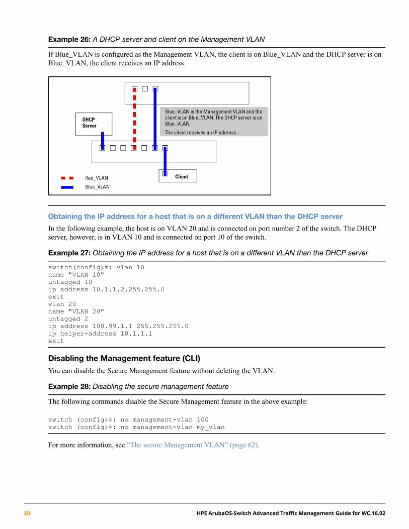
Example 26: A DHCP server and client on the Management VLAN
If Blue_VLAN is configured as the Management VLAN, the client is on Blue_VLAN and the DHCP server is onBlue_VLAN, the client receives an IP address.
Obtaining the IP address for a host that is on a different VLAN than the DHCP server
In the following example, the host is on VLAN 20 and is connected on port number 2 of the switch. The DHCPserver, however, is in VLAN 10 and is connected on port 10 of the switch.
Example 27: Obtaining the IP address for a host that is on a different VLAN than the DHCP server
switch(config)#: vlan 10name "VLAN 10"untagged 10ip address 10.1.1.2.255.255.0exitvlan 20name "VLAN 20"untagged 2ip address 100.99.1.1 255.255.255.0ip helper-address 10.1.1.1exit
Disabling the Management feature (CLI)
You can disable the Secure Management feature without deleting the VLAN.
Example 28: Disabling the secure management feature
The following commands disable the Secure Management feature in the above example:
switch (config)#: no management-vlan 100switch (config)#: no management-vlan my_vlan
For more information, see “The secure Management VLAN” (page 62).
50 HPE ArubaOS-Switch Advanced Traffic Management Guide for WC.16.02

Changing the number of VLANs allowed on the switch (CLI)
Syntax:
The default VLAN number is 1.
max-vlans <1-1022>
Default number of VLANs: 256
In the default VLAN configuration, the switch allows a maximum of 256 VLANs. Use this command to specify themaximum VLANs to allow and specify any value from 1 to 1022.
While IPv6 VLANs maximum is unchanged, the total number of allowed IPVLANs (IPv6 + IPv4) is 512.
If GVRP is enabled, this setting includes any dynamic VLANs on the switch. As part of implementinga new setting, you must execute a write memory command to save the new value to thestartup-config file and then reboot the switch.
If multiple VLANs exist on the switch, you cannot reset the maximum number of VLANs to avalue smaller than the current number of VLANs.
MAX Number of VLANsAttribute
2920 Switch Series (J9836A, J9726A-J9729A); WB Code
1022VLAN
512 total with up to:IP VLAN• 512 IPv4
• 256 IPv6
256 totalstatic routes
The following example shows the command sequence for changing the number of VLANs allowed to 10. You canexecute the commands to write memory and boot at another time.
Chapter 2 VLANs 51
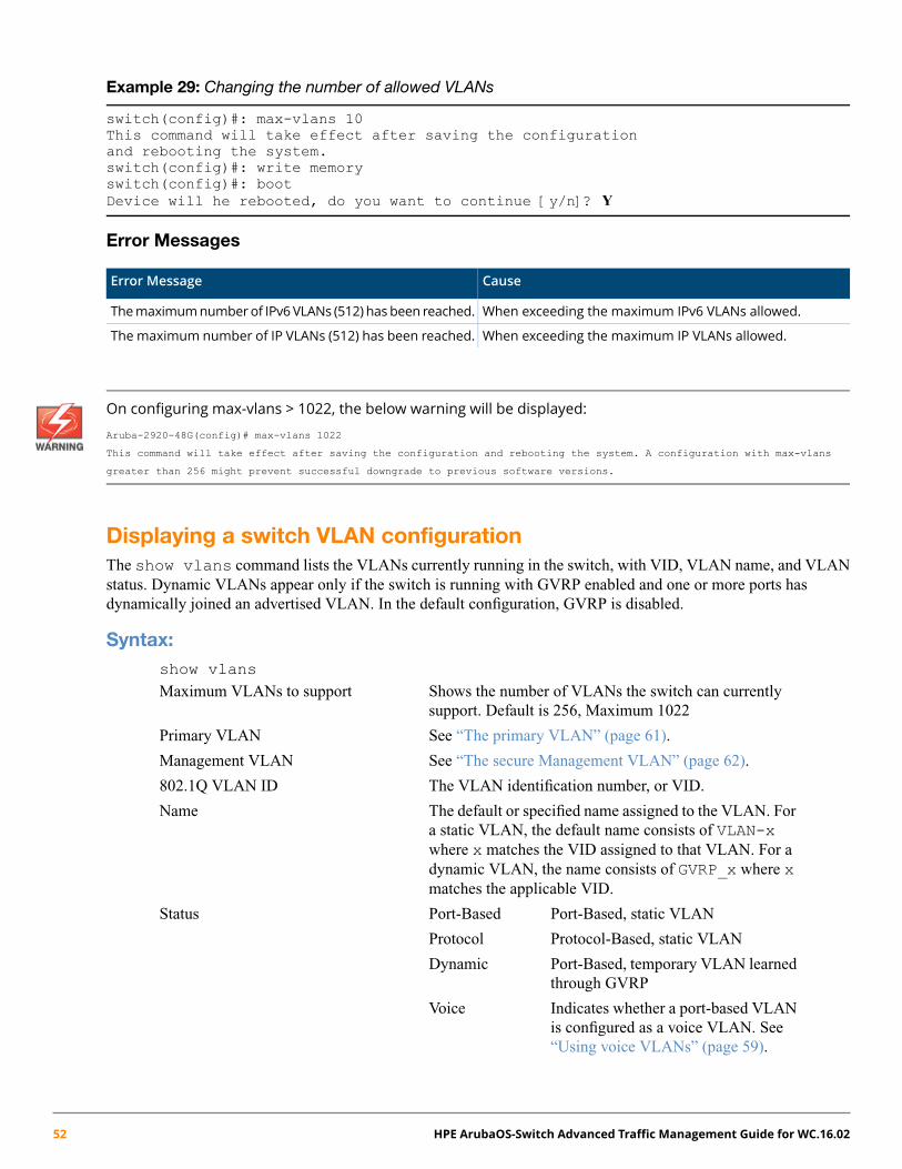
Example 29: Changing the number of allowed VLANs
switch(config)#: max-vlans 10This command will take effect after saving the configurationand rebooting the system.switch(config)#: write memoryswitch(config)#: bootDevice will he rebooted, do you want to continue [y/n]? Y
Error Messages
CauseError Message
When exceeding the maximum IPv6 VLANs allowed.Themaximumnumberof IPv6VLANs (512) has been reached.
When exceeding the maximum IP VLANs allowed.The maximum number of IP VLANs (512) has been reached.
On configuring max-vlans > 1022, the below warning will be displayed:
Aruba-2920–48G(config)# max-vlans 1022
This command will take effect after saving the configuration and rebooting the system. A configuration with max-vlans
greater than 256 might prevent successful downgrade to previous software versions.
Displaying a switch VLAN configurationThe show vlans command lists the VLANs currently running in the switch, with VID, VLAN name, and VLANstatus. Dynamic VLANs appear only if the switch is running with GVRP enabled and one or more ports hasdynamically joined an advertised VLAN. In the default configuration, GVRP is disabled.
Syntax:show vlansMaximum VLANs to support Shows the number of VLANs the switch can currently
support. Default is 256, Maximum 1022
Primary VLAN See “The primary VLAN” (page 61).
Management VLAN See “The secure Management VLAN” (page 62).
802.1Q VLAN ID The VLAN identification number, or VID.
Name The default or specified name assigned to the VLAN. Fora static VLAN, the default name consists of VLAN-xwhere x matches the VID assigned to that VLAN. For adynamic VLAN, the name consists of GVRP_x where xmatches the applicable VID.
Status Port-Based, static VLANPort-Based
Protocol Protocol-Based, static VLAN
Dynamic Port-Based, temporary VLAN learnedthrough GVRP
Voice Indicates whether a port-based VLANis configured as a voice VLAN. See“Using voice VLANs” (page 59).
52 HPE ArubaOS-Switch Advanced Traffic Management Guide for WC.16.02
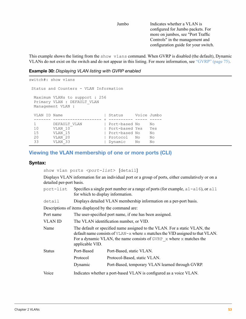
Jumbo Indicates whether a VLAN isconfigured for Jumbo packets. Formore on jumbos, see "Port TrafficControls" in the management andconfiguration guide for your switch.
This example shows the listing from the show vlans command. When GVRP is disabled (the default), DynamicVLANs do not exist on the switch and do not appear in this listing. For more information, see “GVRP” (page 75).
Example 30: Displaying VLAN listing with GVRP enabled
switch#: show vlans
Status and Counters - VLAN Information
Maximum VLANs to support : 256Primary VLAN : DEFAULT_VLANManagement VLAN :
VLAN ID Name | Status Voice Jumbo------- -------------------- + ---------- ----- -----1 DEFAULT_VLAN | Port-based No No10 VLAN_10 | Port-based Yes Yes15 VLAN_15 | Port-based No No20 VLAN_20 | Protocol No No33 VLAN_33 | Dynamic No No
Viewing the VLAN membership of one or more ports (CLI)
Syntax:
show vlan ports <port-list> [detail]
Displays VLAN information for an individual port or a group of ports, either cumulatively or on adetailed per-port basis.
port-list Specifies a single port number or a range of ports (for example, a1-a16), or allfor which to display information.
detail Displays detailed VLAN membership information on a per-port basis.
Descriptions of items displayed by the command are:
Port name The user-specified port name, if one has been assigned.
VLAN ID The VLAN identification number, or VID.
Name The default or specified name assigned to the VLAN. For a static VLAN, thedefault name consists ofVLAN-xwherexmatches the VID assigned to that VLAN.For a dynamic VLAN, the name consists of GVRP_x where x matches theapplicable VID.
Status Port-Based, static VLAN.Port-Based
Protocol Protocol-Based, static VLAN.
Dynamic Port-Based, temporary VLAN learned through GVRP.
Voice Indicates whether a port-based VLAN is configured as a voice VLAN.
Chapter 2 VLANs 53

Jumbo Indicates whether a VLAN is configured for jumbo packets. For more on jumbos,see "Port Traffic Controls" in the management and configuration guide for yourswitch.
Mode Indicates whether a VLAN is tagged or untagged.
Example 31: Displaying VLAN ports (cumulative listing)
switch(config)#:show vlan ports a1-a24
Status and Counters - VLAN Information - for ports A1-A24
VLAN ID Name | Status Voice Jumbo------- -------------------- + ---------- ----- -----1 DEFAULT_VLAN | Port-based No No10 VLAN_10 | Port-based Yes No15 VLAN_15 | Protocol No No
Example 32: Displaying VLAN ports (detailed listing)
switch(config)#:show vlan ports a1-a3 detail
Status and Counters - VLAN Information - for ports A1
VLAN ID Name | Status Voice Jumbo Mode------- -------------------- + ---------- ----- ----- --------1 DEFAULT_VLAN | Port-based No No Untagged10 VLAN_10 | Port-based Yes No Tagged
Status and Counters - VLAN Information - for ports A2
VLAN ID Name | Status Voice Jumbo Mode------- -------------------- + ---------- ----- ----- --------1 DEFAULT_VLAN | Port-based No No Untagged20 VLAN_20 | Protocol No No Untagged
Status and Counters - VLAN Information - for ports A3
VLAN ID Name | Status Voice Jumbo Mode------- -------------------- + ---------- ----- ----- --------1 DEFAULT_VLAN | Port-based No No Untagged33 VLAN_33 | Port-based No No Tagged
Viewing the configuration for a particular VLAN (CLI)
Syntax:
show vlans <vlan-id>
Uses the VID to identify and display the data for a specific static or dynamic VLAN.
802.1Q VLAN ID The VLAN identification number, or VID.
Name The default or specified name assigned to the VLAN. For a staticVLAN, the default name consists of VLAN-x where x matches theVID assigned to that VLAN. For a dynamic VLAN, the name consistsof GVRP_x where x matches the applicable VID.
Status Port-Based, static VLAN.Port-Based
Protocol Protocol-Based, static VLAN
54 HPE ArubaOS-Switch Advanced Traffic Management Guide for WC.16.02

Dynamic Port-Based, temporary VLAN learned throughGVRP. See “GVRP” (page 75).
Voice Indicates whether a port-based VLAN is configured as a voice VLAN.See “Using voice VLANs” (page 59).
Jumbo Indicates whether a VLAN is configured for Jumbo packets. For moreon jumbos, see "Port Traffic Controls" in the management andconfiguration guide for your switch.
Port Information Lists the ports configured as members of the VLAN.
DEFAULT Shows whether a port is a tagged or untagged member of the listedVLAN.
Unknown VLAN Shows whether the port can become a dynamic member of an unknownVLAN for which it receives an advertisement. GVRP must be enabledto allow dynamic joining to occur.
Status Shows whether the port is participating in an active link.
Chapter 2 VLANs 55

Example 33: Displaying information for a specific static VLAN
switch(config)#:show vlans 22
Status and Counters - VLAN Information - VLAN 22
VLAN ID : 22Name : VLAN22Status : Port-basedVoice : YesJumbo : No
Port Information Mode Unknown VLAN Status---------------- -------- ------------ ----------12 Untagged Learn Up13 Untagged Learn Up14 Untagged Learn Up15 Untagged Learn Down16 Untagged Learn Up17 Untagged Learn Up18 Untagged Learn Up
Example 34: Displaying information for a specific dynamic VLAN
The following example shows the information displayed for a specific dynamic VLAN. The show vlans commandlists this data when GVRP is enabled and at least one port on the switch has dynamically joined the designatedVLAN.
switch(config)#: show vlans 22
Status and Counters - VLAN Information - VLAN 22
VLAN ID : 33Name : GVRP_33Status : DynamicVoice : NoJumbo : No
Port Information Mode Unknown VLAN Status---------------- -------- ------------ ----------6 Auto Learn Up
Customizing the show VLANs output (CLI)
Syntax
show vlans custom [port <port-list>] <column-list>
Specifies the order you want information to display for the show vlans command. Displaysinformation for one port or a range of ports. If <port-list> is not specified, all ports display.
56 HPE ArubaOS-Switch Advanced Traffic Management Guide for WC.16.02

Fields that can be included in the customized display:
Default widthExampleDisplayField
65VLAN idid
32Vlan55VLAN namename
10Port-basedStatusstatus
5NoVoice enabledvoice
5NoJumbosenabledjumbo
10ManualHow the IPaddress wasconfigured
ipconfigDisabledDHCP/BootP
15 for IPv410.10.10.3The IPaddresses
ipaddr (IPv4)ipaddr (IPv6) 46 for IPv6fe80::212:79ff:fe8d:8000
15255.255.255.6The subnetmasks
ipmask/64 (prefix for IPv6 is in format"/XX")
5NoWhether proxyARP isconfigured
proxyarp
9NoWhether localproxy ARP isconfigured
localproxyarp
5Up"Up" if at leastone port is up
state
Example 35: Customizing the VLAN display
The following example displays id at its default width and name:20 allows up to 20 characters of the VLANname to be displayed. The columns selected for display are separated by spaces.
If the width of the column requested is smaller than the header name of the column, the display of the header nameis truncated.
switch(config)#: show vlan custom A1-A3 id name:20 ipaddr state
Status and Counters - VLAN Information - Custom view
VLANID VLAN name IP Addr State------ -------------------- --------------------------------- -----1 DEFAULT_VLAN 15.255.134.74 Up33 Vlan33 10.10.10.01 Up44 Vlan44 15.255.164.13 Up55 Vlan55 15.255.178.2 Down
15.255.178.315.255.178.4
60 Vlan60 fe80::212:79ff:fe8d:8000%vlan60 Up
Chapter 2 VLANs 57

Example 36: Wrapping column headers
The total output wraps if it is longer than the terminal width; it is not truncated.
switch(config)#: show vlan custom idStatus and Counters - VLAN Information - Custom view
VLANID------13344
switch(config)#: show vlan custom id:2Status and Counters - VLAN Information - Custom view
VL--13344
Using pattern matching with the show VLANs custom command
If a pattern matching command is in a search for a field in the output of the show vlan custom command andit produces an error, the error message may not be visible. For example, if you enter a command with the patternmatching include option that contains an error (such as 'vlan' is misspelled) as in the following example, theoutput may be empty:
switch(config)#: show vlans custom 1-3 name vlun include vlan1
Hewlett Packard Enterprise recommends that you try the show vlans custom command first to ensure thatthere is output and then enter the command again with the pattern matching option.
Creating an alias for show VLAN commands (CLI)Create an alias for a frequently used show vlans custom command to avoid entering the selected columnseach time you use the command.
58 HPE ArubaOS-Switch Advanced Traffic Management Guide for WC.16.02
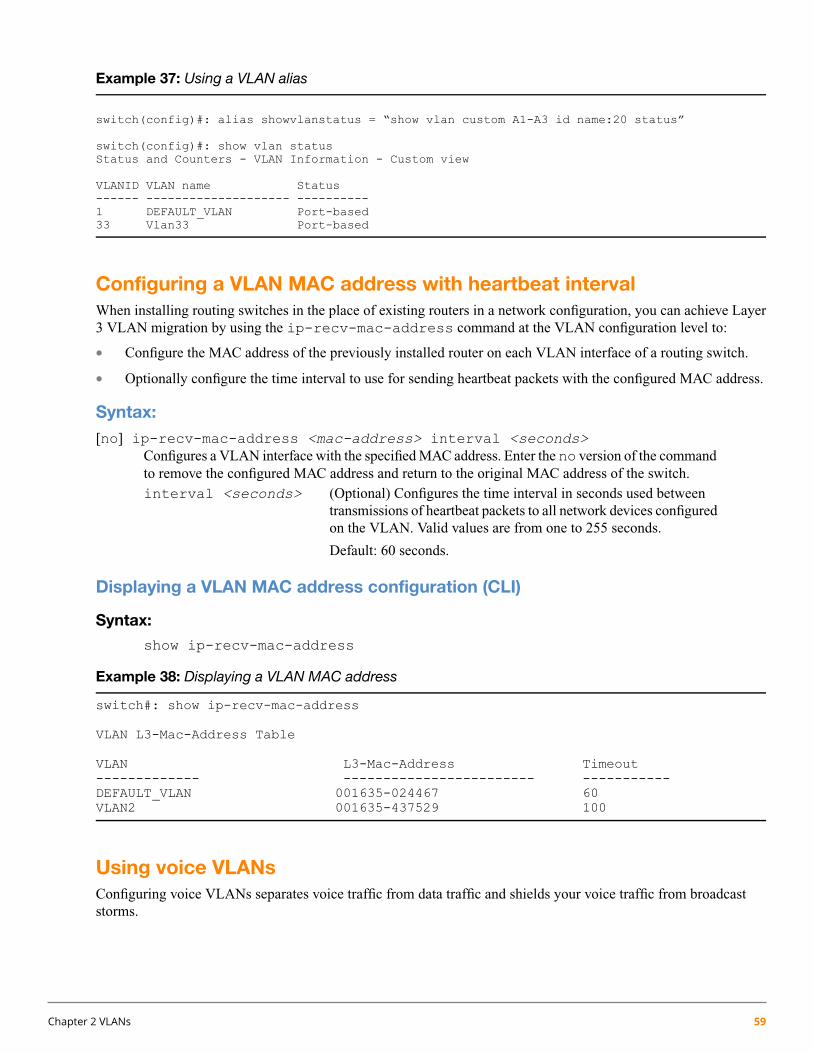
Example 37: Using a VLAN alias
switch(config)#: alias showvlanstatus = “show vlan custom A1-A3 id name:20 status”
switch(config)#: show vlan statusStatus and Counters - VLAN Information - Custom view
VLANID VLAN name Status------ -------------------- ----------1 DEFAULT_VLAN Port-based33 Vlan33 Port-based
Configuring a VLAN MAC address with heartbeat intervalWhen installing routing switches in the place of existing routers in a network configuration, you can achieve Layer3 VLAN migration by using the ip-recv-mac-address command at the VLAN configuration level to:
• Configure the MAC address of the previously installed router on each VLAN interface of a routing switch.
• Optionally configure the time interval to use for sending heartbeat packets with the configured MAC address.
Syntax:[no] ip-recv-mac-address <mac-address> interval <seconds>
Configures a VLAN interface with the specified MAC address. Enter the no version of the commandto remove the configured MAC address and return to the original MAC address of the switch.interval <seconds> (Optional) Configures the time interval in seconds used between
transmissions of heartbeat packets to all network devices configuredon the VLAN. Valid values are from one to 255 seconds.
Default: 60 seconds.
Displaying a VLAN MAC address configuration (CLI)
Syntax:
show ip-recv-mac-address
Example 38: Displaying a VLAN MAC address
switch#: show ip-recv-mac-address
VLAN L3-Mac-Address Table
VLAN L3-Mac-Address Timeout------------- ------------------------ -----------DEFAULT_VLAN 001635-024467 60VLAN2 001635-437529 100
Using voice VLANsConfiguring voice VLANs separates voice traffic from data traffic and shields your voice traffic from broadcaststorms.
Chapter 2 VLANs 59

Operating rules for voice VLANs
• You must statically configure voice VLANs. GVRP and dynamic VLANs do not support voice VLAN operation.
• Configure all ports in a voice VLAN as tagged members of the VLAN. This ensures retention of the QoS(Quality of Service) priority included in voice VLAN traffic moving through your network.
• If a telephone connected to a voice VLAN includes a data port used for connecting other networked devices(such as PCs) to the network, then you must configure the port as a tagged member of the voice VLAN and atagged or untagged member of the data VLAN you want the other networked device to use.
Components of voice VLAN operation
• Voice VLAN: Configure one or more voice VLANs on the switch. Some reasons for having multiple voiceVLANs include:
• Employing telephones with different VLAN requirements
• Better control of bandwidth usage
• Segregating telephone groups used for different, exclusive purposes
Where multiple voice VLANs exist on the switch, you can use routing to communicate between telephones ondifferent voice VLANs.
• Tagged/Untagged VLAN Membership: If the appliances using a voice VLAN transmit tagged VLAN packets,then configure the member ports as tagged members of the VLAN. Otherwise, configure the ports as untaggedmembers.
Voice VLAN access securityYou can use port security configured on an individual port or group of ports in a voice VLAN. That is, you canallow or deny access to a phone having a particular MAC address. See chapter titled "Configuring and MonitoringPort Security" in the access security guide for your switch.
MAC authentication is not recommended in voice VLAN applications.
Prioritizing voice VLAN QoS (Optional)Without configuring the switch to prioritize voice VLAN traffic, one of the following conditions applies:
• If the ports in a voice VLAN are not tagged members, the switch forwards all traffic on that VLAN at "normal"priority.
• If the ports in a voice VLAN are tagged members, then the switch forwards all traffic on that VLAN at whateverpriority the traffic has when received inbound on the switch.
Using the switch's QoS VLAN-ID (VID) priority option, you can change the priority of voice VLAN traffic movingthrough the switch. If all port memberships on the voice VLAN are tagged, the priority level you set for voice VLANtraffic is carried to the next device. With all ports on the voice VLAN configured as tagged members, you can enforcea QoS priority policy moving through the switch and through your network.
Syntax:
vlan <vid> qos priority <0-7>
The qos priority default setting is 0 (normal), with 1 as the lowest priority and 7 as the highestpriority.
60 HPE ArubaOS-Switch Advanced Traffic Management Guide for WC.16.02

If you configure a voice VLAN with a VID of 10 and want the highest priority for all traffic on thisVLAN, execute the following commands:
switch(config) #: vlan 10 qos priority 7switch (config) #: write memory
You also have the option of resetting the DSCP (DiffServe Codepoint) on tagged voice VLANtraffic moving through the switch. For more information, see “Quality of Service (QoS): Managingbandwidth effectively” (page 186).
If all port memberships on the voice VLAN are tagged:
• The priority level set for voice VLAN traffic is carried to the next device.
• You can enforce a QoS priority policy moving through the switch and network.
For more information, see “Using voice VLANs” (page 59).
Special VLAN types
VLAN support and the default VLANIn the factory default configuration, VLAN support is enabled and all ports on the switch belong to the port-based,default VLAN (named DEFAULT_VLAN). This places all ports in the switch into one physical broadcast domain.In the factory-default state, the default VLAN is also the Primary VLAN.
• You can partition the switch into multiple virtual broadcast domains by configuring one or more additionalVLANs and moving ports from the default VLAN to the new VLANs.
• The switch supports up to 2048 static and dynamic VLANs, with VIDs numbered up to 4094. You can changethe name of the default VLAN, but not its VID, which is always 1.
• You can remove all ports from the default VLAN by placing them in another port-based VLAN, but this VLANremains and cannot be deleted from the switch.
For details on port VLAN settings, see “Configuring or changing static VLAN per-port settings (CLI)” (page 40).
The primary VLANAs certain features and management functions run on only one VLAN in the switch and because DHCP and Bootpcan run per-VLAN, there is a need for a dedicated VLAN to manage these features and ensure that multiple instancesof DHCP or Bootp on different VLANs do not result in conflicting configuration values for the switch.
The Primary VLAN is the VLAN the switch uses to run and manage these features and data. In the factory-defaultconfiguration, the switch designates the default VLAN (DEFAULT_VLAN; VID=1) as the Primary VLAN. Howeveryou can designate another static, port-based VLAN as primary.
To summarize, designating a non-default VLAN as primary means that:
• The switch reads DHCP responses on the Primary VLAN instead of on the default VLAN. This includes suchDHCP-resolved parameters as the TimeP server address, Default TTL and IP addressing—including the GatewayIP address—when the switch configuration specifies DHCP as the source for these values.
• The default VLAN continues to operate as a standard VLAN you cannot delete it or change its VID.
• Any ports not specifically assigned to another VLAN will remain assigned to the Default VLAN, even if it isthe Primary VLAN.
Candidates for Primary VLAN include any static, port-based VLAN currently configured on the switch.
Chapter 2 VLANs 61

Protocol-Based VLANs and dynamic (GVRP-learned) VLANs that have not been converted to a static VLAN cannotbe the Primary VLAN. To display the current Primary VLAN, use the CLI show vlan command.
If you configure a non-default VLAN as the Primary VLAN, you cannot delete that VLAN unless you first selecta different VLAN to serve as primary.
If youmanually configure a gateway on the switch, it ignores any gateway address received via DHCP or Bootp.
To change the Primary VLAN configuration, see “Changing VLAN support settings (Menu)” (page 34).
The secure Management VLANConfiguring a secure Management VLAN creates an isolated network for managing the switches that support thisfeature. Access to a secure Management VLAN and the switch's management functions (Menu and CLI), is availableonly through ports configured as members.
• Multiple ports on the switch can belong to the Management VLAN. This allows connections for multiplemanagement stations to the Management VLAN, while allowing Management VLAN links between switchesconfigured for the same Management VLAN.
• Only traffic from the Management VLAN can manage the switch, which means that only the workstations andPCs connected to ports belonging to the Management VLAN can manage and reconfigure the switch.
Example 39: Potential security breaches in a network
This illustrates use of the Management VLAN feature to support management access by a group of managementworkstations.
Example 40: Management VLAN control in a LAN
In this example, Workstation 1 has management access to all three switches through the Management VLAN, whilethe PCs do not. This is because configuring a switch to recognize a Management VLAN automatically excludesattempts to send management traffic from any other VLAN.
62 HPE ArubaOS-Switch Advanced Traffic Management Guide for WC.16.02
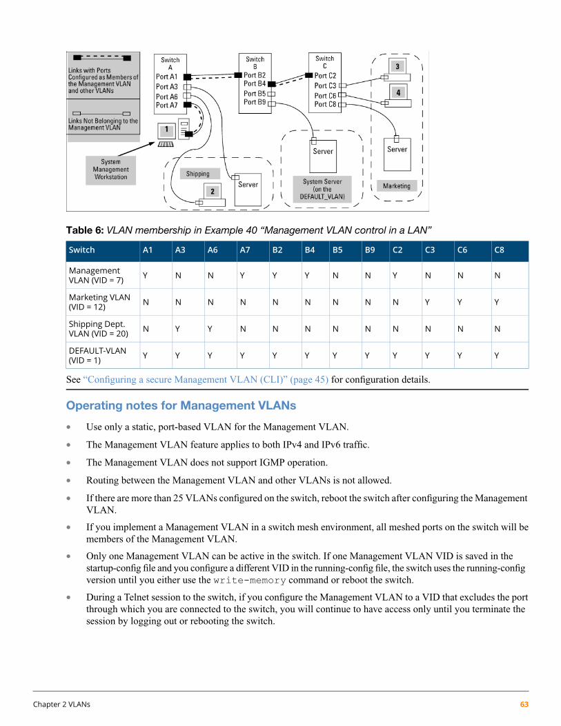
Table 6: VLAN membership in Example 40 “Management VLAN control in a LAN”
C8C6C3C2B9B5B4B2A7A6A3A1Switch
NNNYNNYYYNNYManagementVLAN (VID = 7)
YYYNNNNNNNNNMarketing VLAN(VID = 12)
NNNNNNNNNYYNShipping Dept.VLAN (VID = 20)
YYYYYYYYYYYYDEFAULT-VLAN(VID = 1)
See “Configuring a secure Management VLAN (CLI)” (page 45) for configuration details.
Operating notes for Management VLANs
• Use only a static, port-based VLAN for the Management VLAN.
• The Management VLAN feature applies to both IPv4 and IPv6 traffic.
• The Management VLAN does not support IGMP operation.
• Routing between the Management VLAN and other VLANs is not allowed.
• If there are more than 25 VLANs configured on the switch, reboot the switch after configuring the ManagementVLAN.
• If you implement a Management VLAN in a switch mesh environment, all meshed ports on the switch will bemembers of the Management VLAN.
• Only one Management VLAN can be active in the switch. If one Management VLAN VID is saved in thestartup-config file and you configure a different VID in the running-config file, the switch uses the running-configversion until you either use the write-memory command or reboot the switch.
• During a Telnet session to the switch, if you configure the Management VLAN to a VID that excludes the portthrough which you are connected to the switch, you will continue to have access only until you terminate thesession by logging out or rebooting the switch.
Chapter 2 VLANs 63

The Management VLAN feature does not control management access through a direct connection to theswitch's serial port.
• During a WebAgent session, if you configure the Management VLAN to a VID that excludes the port throughwhich you are connected to the switch, you will continue to have access only until you close the browser sessionor reboot the switch.
• Enabling Spanning Tree between a pair of switches where there are multiple links using separate VLANs,including the Management VLAN, will force the blocking of one or more links. This may include the linkcarrying the Management VLAN, which will cause loss of management access to some devices. This can alsooccur where meshing is configured and the Management VLAN is configured on a separate link.
• Monitoring Shared Resources: The Management VLAN feature shares internal switch resources with severalother features. The switch provides ample resources for all features. However, if the internal resources becomefully subscribed, the Management VLAN feature cannot be configured until the necessary resources are releasedfrom other uses. For information on determining the current resource availability and usage, see the appendixtitled "Monitoring Resources" in the management and configuration guide for your switch.
Example 41: Inadvertently blocking a Management VLAN link by implementing spanning tree
VLAN operating notesDisabled overlapping subnetconfiguration
Previous software versions allowed configuration of VLAN IP addressesin overlapping subnets, which can cause incorrect routing of packets andresult in IP communication failure. As of software version xx.15.09,overlapping subnet configurations are no longer allowed. An overlappingsubnet is determined by the configuration order. The subnet that isconfigured first is valid, but any subsequent IP addresses that overlap arenot allowed.
When the switch is booted into software version xx.15.09 or later and theconfiguration file includes overlapping subnets, the following occurs:
• The event log provides an error message in the format:
64 HPE ArubaOS-Switch Advanced Traffic Management Guide for WC.16.02

ip: VLANx : IP initialization failed for vlan x.
For a multinetted VLAN (multiple IP addresses assigned to theVLAN), only the IP addresses that are overlapping subnets areremoved. The other IP addresses on the VLAN are retained andfunction correctly. The error message can be misleading; the IPaddresses on the VLAN that are not overlapping are initializedcorrectly.
• The output of the show ip command correctly indicates that theoverlapping IP address does not exist on the VLANs that have errormessages in the event log.
• The output of the show running-config command incorrectlyindicates that the overlapping IP address is configured. For example,in the following output, the IP address shown in VLAN6 is notactually configured on the VLAN; it has been removed.
Example 42: An IP address that is not actually configured onthe VLAN
switch(config)#: show running-config
.
.
.vlan 5
name “VLAN5”ip address 11.22.33.1 255.0.0.0exit
vlan 6name “VLAN6”ip address 11.23.34.1 255.255.255.0exit
The information is retained in the config file to allow you to boot up theswitch and have it function as it did when it was configured with earliersoftware that allows overlapping subnets. This occurs because theoverlapping IP address has been removed and is not visible to the switch.To resolve this:
If you attempt to remove the overlapping subnet from the VLAN, theswitch displays an error message similar to:
The IP address <ip address> is not configured on this VLAN
This occurs because the overlapping IP address has been removed and isnot visible to the switch. To resolve this:
• Enter the show ip command to determine which addresses arevisible to the switch.
• Remove the erroneous IP addresses from the config file by enteringthe no ip address command to remove all the IP addressesfrom the specific VLAN. Be sure to document the other valid IPaddresses on that VLAN so they can be restored after removing theerroneous IP addresses from the config file.
Chapter 2 VLANs 65
If you go back to a software version before xx.15.09 before removing theoverlapping IP address, the prior software version enables the overlappingIP subnet.
DHCP/Bootp If you are using DHCP/Bootp to acquire the switch's configuration, packettime-to-live and TimeP information, designates the VLAN on which DHCPis configured as the Primary VLAN.
In the factory-default configuration, the DEFAULT_VLAN is the PrimaryVLAN.
Per-VLAN features IGMP and some other features operate on a per VLAN basis. This meansyou must configure such features separately for each VLAN in which youwant them to operate.
Default VLAN You can rename the default VLAN, but you cannot change its VID (1) ordelete it from the switch.
VLAN port assignments Any ports not specifically removed from the default VLAN remain in theDEFAULT_VLAN, regardless of other port assignments. Also, a port mustalways be a tagged or untagged member of at least one port-based VLAN.
Voice-Over-IP (VoIP) VoIP operates only over static, port-based VLANs.
Multiple VLAN types configured on thesame port
A port can simultaneously belong to both port-based and protocol-basedVLANs.
Protocol Capacity A protocol-based VLAN can include up to four protocol types. In protocolVLANs using the IPv4 protocol, to support normal IP network operationARP must be one of these protocol types (to support normal IP networkoperation). Otherwise, IP traffic on the VLAN is disabled.
If you configure an IPv4 protocol VLAN that does not include the ARPVLAN protocol, the switch displays the following message which indicatesa protocol VLAN configured with IPv4 but not ARP:
switch(config)#: vlan 97 protocol ipv4
IPv4 assigned without ARP, this may result inundeliverable IP packets.
Deleting Static VLANs A VLAN can be deleted even if there are currently ports belonging to it.The ports are moved to the default VLAN.
Adding or Deleting VLANs Changing the number of VLANs supported on the switch, requires a reboot.
From the CLI, you must perform a write memory command beforerebooting. Other VLAN configuration changes are dynamic.
66 HPE ArubaOS-Switch Advanced Traffic Management Guide for WC.16.02

Effects of VLANs on other switch features
Spanning Tree operation with VLANsDepending on the spanning tree option configured on the switch, the spanning tree feature may operate as:
• A single instance across all ports on the switch regardless of VLAN assignments
• Multiple instances per-VLAN
For single-instance operation, if redundant physical links exist between the switch and another 802.1Q device, allbut one link will be blocked, even if the redundant links are in separate VLANs. In this case, you can use porttrunking to prevent Spanning Tree from unnecessarily blocking ports (and to improve overall network performance).For multiple-instance operation, physically redundant links belonging to different VLANs can remain open. Formore information, see “Multiple Instance Spanning Tree Operation” (page 104).
Spanning Tree operates differently in different devices. For example, in the (obsolete, non-802.1Q) Switch 2000and the Switch 800T, Spanning Tree operates per-VLAN, allowing redundant physical links as long as they arein separate VLANs.
Spanning Tree operates differently in different devices
IP interfaces
There is a one-to-one relationship between a VLAN and an IP network interface. Since the VLAN is defined by agroup of ports, the state (up/down) of those ports determines the state of the IP network interface associated withthat VLAN. When a port-based VLAN or an IPv4 or IPv6 protocol-based VLAN comes up because one or more ofits ports is up, the IP interface for that VLAN is also activated. Likewise, when a VLAN is deactivated because allof its ports are down, the corresponding IP interface is also deactivated.
VLAN MAC address
The switches have one unique MAC address for all of their VLAN interfaces. You can send an 802.2 test packet tothis MAC address to verify connectivity to the switch and you can assign an IP address to the VLAN interface.When you Ping that address, ARP will resolve the IP address to this single MAC address.
In a topology where a switch has multiple VLANs and must be connected to a device having a single forwardingdatabase, such as the Switch 4000M, some cabling restrictions apply. For more on this topic, see “Multiple VLANconsiderations” (page 30).
Port trunks
When assigning a port trunk to a VLAN, all ports in the trunk are automatically assigned to the same VLAN. Donot split trunk members across multiple VLANs. A port trunk is tagged, untagged, or excluded from a VLAN thesame way as individual, untrunked ports.
Port monitoring
If you designate a port on the switch for network monitoring, the port will appear in the Port VLAN Assignmentscreen and can be configured as a member of any VLAN. For information on how broadcast, multicast and unicastpackets are tagged inside and outside of the VLAN to which the monitor port is assigned, see the section titled"VLAN-Related Problems" in the "Troubleshooting" appendix of the management and configuration guide for yourswitch.
Chapter 2 VLANs 67

Jumbo packet support
Jumbo packet support is enabled per-VLAN and applies to all ports belonging to the VLAN. For more information,see the chapter titled "Port Traffic Controls" in the management and configuration guide for your switch.
VLAN restrictions
• A port must be a member of at least one VLAN. In the factory default configuration, all ports are assigned tothe default VLAN (DEFAULT_VLAN; VID=1).
• A port can be a member of one untagged, port-based VLAN. All other port-based VLAN assignments for thatport must be tagged. The "Untagged" designation enables VLAN operation with non 802.1Q-compliant devices.
• A port can be an untagged member of one protocol-based VLAN of each protocol type. When assigning a portto multiple, protocol-based VLANs sharing of the same type, the port can be an untagged member of only onesuch VLAN.
• With routing enabled on the switch, the switch can route traffic between:
Multiple, port-based VLANs•
• A port-based VLAN and an IPv4 protocol-based VLAN
• A port-based VLAN and an IPv6 protocol-based VLAN
• An IPv4 protocol-based VLAN and an IPv6 protocol VLAN
Other, routable, protocol-based VLANs must use an external router to move traffic between VLANs. Withrouting disabled, all routing between VLANs must be through an external router.
• Before deleting a static VLAN, t first reassign all ports in the VLAN to another VLAN. You can use the novlan <vid> command to delete a static VLAN. For more information, see “Creating a new static VLAN(port-based or protocol-based) (CLI) ” (page 38).
• Protocol-based VLANs, port-based VLANs and LLDP radio port VLANs cannot run concurrently with RPVST+.
Migrating Layer 3 VLANs using VLAN MAC configurationSwitches provide for maintaining Layer 3 VLAN configurations when migrating distribution routers in networksnot centrally managed, by configuring the MAC address of the previous router on the VLAN interfaces of the routingswitch.
VLAN MAC address reconfigurationSwitches use one unique MAC address for all VLAN interfaces. If you assign an IP address to a VLAN interface,ARP resolves the IP address to the MAC address of the routing switch for all incoming packets.
The Layer 3 VLAN MAC Configuration feature lets you reconfigure the MAC address used for VLAN interfaces,using the CLI. Packets addressed to the reconfigured Layer 3 MAC address, such as ARP and IP data packets, arereceived and processed by the routing switch.
Packets transmitted from the routing switch (packets originating from the router and forwarded packets) use theoriginal Switch MAC address as the source MAC address in Ethernet headers.
ARP reply packets use the reconfigured MAC address in both the:
• ARP Sender MAC address field
• Source MAC address field in the Ethernet frame header
68 HPE ArubaOS-Switch Advanced Traffic Management Guide for WC.16.02

When reconfiguring the MAC address, you may specify a keepalive timeout to transmit heartbeat packets thatadvertise the new MAC address
By configuring the MAC address of the previously installed router as the MAC address of each VLAN interface onthe Switch, you can swap the physical port of a router to the Switch after the switch has been properly configuredin the network.
Handling incoming and outgoing VLAN Traffic
Incoming VLAN data packets and ARP requests
These are received and processed on the routing switch according to the MAC address of the previously installedrouter configured for each VLAN interface.
Outgoing VLAN traffic
This uses the MAC address of the switch as the source MAC address in packet headers. The MAC address configuredon VLAN interfaces is not used on outbound VLAN traffic.
When the routing switch receives an ARP request for the IP address configured on a VLAN interface, the ARP replyuses the reconfigured MAC address in both the:
• ARP Sender MAC address field
• Source MAC address field in the Ethernet frame header
When proxy ARP is enabled on a VLAN interface, the "gracious" ARP reply sent for an ARP request received fromVLAN devices located outside the directly connected IP subnets also contains the reconfigured MAC address inboth the:
• ARP Sender MAC address field
• Source MAC address field in the Ethernet frame header
The Virtual Router Redundancy Protocol (VRRP) is not supported on VLAN interfaces onwhich theMAC addressfor incoming traffic has been reconfigured.
To hosts in the network, VLAN traffic continues to be routed (using the reconfigured MAC address as destinationaddress), but outbound VLAN traffic appears to be sent from another router attached to the same subnet (using theSwitch MAC address as source address) attached to the same subnet. Although it appears as an asymmetric path tonetwork hosts, the MAC address configuration feature enables Layer 3 VLAN migration. (A successful VLANmigration is achieved because the hosts do not verify that the source MAC address and the destination MAC addressare the same when communicating with the routing switch.)
Sending heartbeat packets with a configured MAC AddressOn the VLAN interfaces of a routing switch, the user-defined MAC address only applies to inbound traffic. As aresult, any connected switches need to learn the new address that is included in the Ethernet frames of outboundVLAN traffic transmitted from the routing switch.
If a connected switch does not have the newly configured MAC address of the routing switch as a destination in itsMAC address table, it floods packets to all of its ports until a return stream allows the switch to learn the correctdestination address. As a result, the performance of the switch is degraded as it tries to send Ethernet packets to anunknown destination address.
To allow connected switches to learn the user-configured MAC address of a VLAN interface, the routing switchcan send periodic heartbeat-like Ethernet packets. The Ethernet packets contain the configured MAC address as the
Chapter 2 VLANs 69

source address in the packet header. IP multicast packets or Ethernet service frames are preferred because they donot interrupt the normal operation of client devices connected on the segment.
Because the aging time of destination addresses in MAC address tables varies on network devices, you must alsoconfigure a time interval to use for sending heartbeat packets.
Heartbeat packets are sent at periodic intervals with a specific Switch unicast MAC address in the destination field.This MAC address is assigned to the Switch and is not used by other non- routers. Because the heartbeat packetcontains a unicast MAC address, it does not interrupt host operation. Even if you have multiple 1-65 Static VirtualLANs (VLANs) Introducing tagged VLAN technology into networks running untagged VLANs switches connectedto the network, there is no impact on network performance because each switch sends heartbeat packets with itsconfigured MAC address as the destination address.
The format of a heartbeat packet is an extended Ethernet OUI frame with an extended OUI Ethertype (88B7) and anew protocol identifier in the 5-octet protocol identifier field.
Configuring a VLAN MAC address with heartbeat intervalWhen installing routing switches in place of existing routers in a network configuration, you can achieve Layer 3VLAN migration by using the ip-recv-mac-address command at the VLAN configuration level to:
• Configure the MAC address of the previously installed router on each VLAN interface of a routing switch.
• Optionally configure the time interval to use for sending heartbeat packets with the configured MAC address.
Syntax:
[no] ip-recv-mac-address <mac-address> [interval <seconds>]ip-recv-mac-address <<mac-address>>
Configures a VLAN interface with the specified MAC address. Enter the no version of the commandto remove the configured MAC address and return to the original MAC address of the switch.
interval <seconds>
(Optional) Configures the time interval, in seconds (1 to 255, default: 60), used between transmissionsof heartbeat packets to all network devices configured on the VLAN.
Operating notes
• The ip-recv-mac-address command lets you configure only one MAC address for a specified VLAN.If you re-enter the command to configure another MAC address, the previously configured MAC address isoverwritten.
• Enter the no form of the command to remove a configured MAC address and restore the default MAC addressof the switch.
• When you configure a VLAN MAC address, you may also specify a heartbeat interval. The interval<seconds> parameter is optional.
• After you configure a VLAN MAC address:
IP router and MAC ARP replies to other VLAN devices contain the user-defined MAC address as theEthernet sender hardware address.
•
• Outbound VLAN traffic contains the Switch MAC address, not the configured MAC address, as the sourceMAC address in packet headers.
• Immediately after you configure a VLAN MAC address or remove a configured MAC address, a gratuitousARP message is broadcast on the connected segment to announce the change of the IP-to-MAC address bindingto all connected IP-based equipment.
70 HPE ArubaOS-Switch Advanced Traffic Management Guide for WC.16.02

• A configured VLAN MAC address supports proxy ARP and gracious ARP.
• A new MIB variable, ifRcvAddressTable, is introduced to support VLAN MAC configuration.
• You cannot configure a VLAN MAC address using the WebAgent or menu interface. You must use the CLI.
• VRRP is not supported on a VLAN interface with a user-configured MAC address.
Example 43: Configuring a MAC address
The following example shows how to configure a MAC address on VLAN 101.
switch#: configure terminalswitch(config)#: vlan 101switch(vlan-101)#: ip-recv-mac-address 0060b0-e9a200 interval 100
Verifying a VLAN MAC address configuration
To verify the configuration of Layer 3 MAC addresses on the VLAN interfaces of a switch, use the showip-recv-mac-address command.
Displaying a VLAN MAC address configuration (CLI)
Syntax:
show ip-recv-mac-address
Example 44: Displaying a VLAN MAC address
switch#: show ip-recv-mac-address
VLAN L3-Mac-Address Table
VLAN L3-Mac-Address Timeout------------- ------------------------ -----------DEFAULT_VLAN 001635-024467 60VLAN2 001635-437529 100
Smart Link
IntroductionSmart link is a switch feature that provides effective, simple, and fast-converging link redundancy in networktopology with dual uplink between different layers of the network. It requires an active (master) and a backup (slave)link. The active link carries the uplink traffic. Upon failure of the active link, a switchover is triggered and the trafficis directed to the backup link.
Chapter 2 VLANs 71

• In the previous figure, ports A1 and A2 are configured as part of a Smart link group. The connection from theaccess switch to Distribution Switch A is the master, and the connection from the access switch to DistributionSwitch B is the slave.
• Only the master interface forwards traffic for a group of VLANs (referred to as protected VLAN group).
• The other interface is in standby mode for this protected group. If port A1 goes down, port A2 starts forwardingtraffic for this protected VLAN group.
• If port A1 comes back up, it goes to standby mode and does not forward traffic. Port A2 continues forwardingtraffic. This is the case if preemption-mode is configured as “role”. If preemption-mode is not configured as“role”, when the master (A1) comes back up, it becomes Active (forwarding) after the configured‘preemption-delay’.
• Since a Smart link group has the information readily available via configuration as to which port should beforwarding for the protected VLAN group in the case of the active link failure, the failover is much quickerwhen compared with STP.
Configuring Smart LinkUse the following commands to configure Smart link:
• Create a smart link group, using optional parameters as necessary:HP-Switch(config)#[no] smart-link group group-id
Options
master portslave portprotected-vlans vid-list
72 HPE ArubaOS-Switch Advanced Traffic Management Guide for WC.16.02

send-control-vlan vidpreemption-mode off | forced | bandwidthpreemption-delay 10...maxtrap enable | disable
When executed without any parameters, this command enters into Smart link group context.
• Configure VLANs to receive flush messages. This is an interface level command. It must be executed for boththe master and the slave port.HP-Switch(config)# smart-link recv-control-vlan vid-list
• Enable debug messages for a Smart link group:HP-Switch(config)#debug smart-link [ group group-id | all ] [flush-packets]
Configuration example
The following example illustrates Smart link configuration with VLAN load-balancing:
• vlans 1-10 mapped to smart-link group 1:
HP-Switch(config)#smart-link group 1 master a1 slave a2HP-Switch(config)#smart-link group 1 protected-vlans 1-10HP-Switch(config)#smart-link group 1 send-control-vlan 1HP-Switch(config)#smart-link group 1 preemption-mode roleHP-Switch(config)#smart-link group 1 preemption-delay 10
• vlans 11-20 mapped to smart-link group 2:
HP-Switch(config)#smart-link group 2 master a2 slave a1HP-Switch(config)#smart-link group 2 protected-vlans 11-20HP-Switch(config)#smart-link group 2 send-control-vlan 10HP-Switch(config)#smart-link group 2 preemption-mode roleHP-Switch(config)#smart-link group 2 preemption-delay 15
Viewing Smart Link informationSmart link supports the following show commands:
• Show the Smart link group information. Detailed output is displayed if group is specified, otherwise only basicinformation is displayed for all groups.show smart-link group { group-id | all }
The H3C-equivalent display command is:
display smart-link group [ group-id | all ] [ begin | exclude | include ]regular-expression
• Show statistics of received flush packetsshow smart-link flush-statistics
The H3C-equivalent display command is:
display smart-link flush [ begin | exclude | include ] regular-expression
• Show receive control VLANs configured on per port basis:show smart-link recv-control-vlans
Chapter 2 VLANs 73

Clearing statisticsUse the following command to clear group and flush statistics
clear smart-link [flush-statistics] [ group group-id | all ]
74 HPE ArubaOS-Switch Advanced Traffic Management Guide for WC.16.02
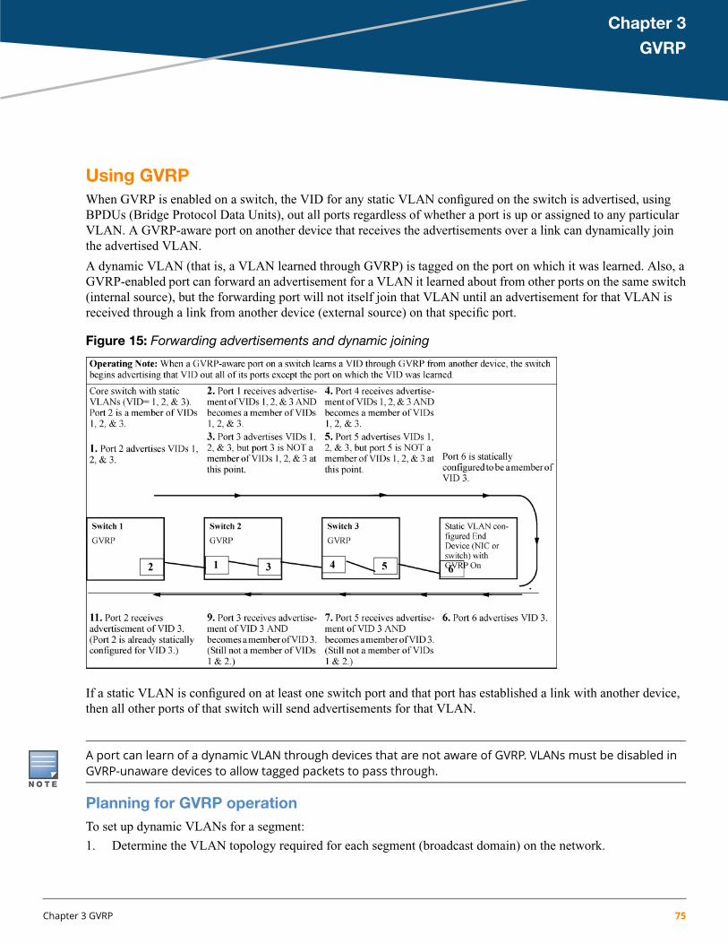
Chapter 3
GVRP
Using GVRPWhen GVRP is enabled on a switch, the VID for any static VLAN configured on the switch is advertised, usingBPDUs (Bridge Protocol Data Units), out all ports regardless of whether a port is up or assigned to any particularVLAN. A GVRP-aware port on another device that receives the advertisements over a link can dynamically jointhe advertised VLAN.
A dynamic VLAN (that is, a VLAN learned through GVRP) is tagged on the port on which it was learned. Also, aGVRP-enabled port can forward an advertisement for a VLAN it learned about from other ports on the same switch(internal source), but the forwarding port will not itself join that VLAN until an advertisement for that VLAN isreceived through a link from another device (external source) on that specific port.
Figure 15: Forwarding advertisements and dynamic joining
If a static VLAN is configured on at least one switch port and that port has established a link with another device,then all other ports of that switch will send advertisements for that VLAN.
A port can learn of a dynamic VLAN through devices that are not aware of GVRP. VLANs must be disabled inGVRP-unaware devices to allow tagged packets to pass through.
Planning for GVRP operationTo set up dynamic VLANs for a segment:
1. Determine the VLAN topology required for each segment (broadcast domain) on the network.
Chapter 3 GVRP 75
2. Determine which VLANs must be static and which can be dynamically propagated.3. Determine the devices on which static VLANs must be manually created to propagate VLANs throughout the
segment.4. Determine security boundaries and how individual ports in the segment are to handle dynamic VLAN
advertisements (see Table 7 (page 80) and Table 8 (page 85)).5. Enable GVRP on all devices to be used with dynamic VLANs and configure the appropriate "Unknown VLAN"
parameter (Learn, Block, or Disable) for each port.6. Configure static VLANs on the switches, where needed, with their per-VLAN parameters (Tagged, Untagged,
Auto, and Forbid—see Table 8 (page 85)) on each port.7. Dynamic VLANs will then appear automatically, according to the chosen configuration options.8. Convert dynamic VLANs to static VLANs, where dynamic VLANs are to become permanent.
Displaying switch current GVRP configuration (CLI)
Syntax:
show gvrp
Shows GVRP status (enabled or disabled), current maximum number of VLANs supported and thecurrent Primary VLAN.
76 HPE ArubaOS-Switch Advanced Traffic Management Guide for WC.16.02

Example 45: Displaying GVRP status with GVRP disabled
switch(config)#: show gvrp
GVRP support
Maximum VLANs to support [256] : 256Primary VLAN : DEFAULT_VLANGVRP Enabled [No] : No
Example 46: Displaying GVRP status with GVRP enabled
This example shows the output for the show gvrp command with GVRP enabled. It includes non-default settingsfor the Unknown VLAN field for some ports (see Port number 3, 4, 5 below).
switch(config)#: show gvrp
GVRP support
Maximum VLANs to support [256] : 256Primary VLAN : DEFAULT_VLANGVRP Enabled [No] : Yes
Port Type | Unknown VLAN Join Leave Leaveall---- --------- + ------------ ----- ----- --------1 10/100TX | Learn 20 300 10002 10/100TX | Learn 20 300 10003 10/100TX | Block 20 300 10004 10/100TX | Disable 20 300 10005 10/100TX | Disable 20 300 10006 10/100TX | Learn 20 300 10007 10/100TX | Learn 20 300 1000
Displaying switch current GVRP configuration (CLI)
Syntax:
show gvrp
Shows GVRP status (enabled or disabled), current maximum number of VLANs supported and thecurrent Primary VLAN.
Chapter 3 GVRP 77

Example 47: Displaying GVRP status with GVRP disabled
switch(config)#: show gvrp
GVRP support
Maximum VLANs to support [256] : 256Primary VLAN : DEFAULT_VLANGVRP Enabled [No] : No
Example 48: Displaying GVRP status with GVRP enabled
This example shows the output for the show gvrp command with GVRP enabled. It includes non-default settingsfor the Unknown VLAN field for some ports (see Port number 3, 4, 5 below).
switch(config)#: show gvrp
GVRP support
Maximum VLANs to support [256] : 256Primary VLAN : DEFAULT_VLANGVRP Enabled [No] : Yes
Port Type | Unknown VLAN Join Leave Leaveall---- --------- + ------------ ----- ----- --------1 10/100TX | Learn 20 300 10002 10/100TX | Learn 20 300 10003 10/100TX | Block 20 300 10004 10/100TX | Disable 20 300 10005 10/100TX | Disable 20 300 10006 10/100TX | Learn 20 300 10007 10/100TX | Learn 20 300 1000
Viewing and configuring GVRP (Menu)
1. From the Main Menu, select: 2. Switch Configuration 8. VLAN Menu 1. VLAN Support
Figure 16: The VLAN Support screen (default configuration)
2. Do the following to enable GVRP and display the Unknown VLAN fields:a. Press E (for Edit).b. Use to move the cursor to the GVRP Enabled field.
78 HPE ArubaOS-Switch Advanced Traffic Management Guide for WC.16.02
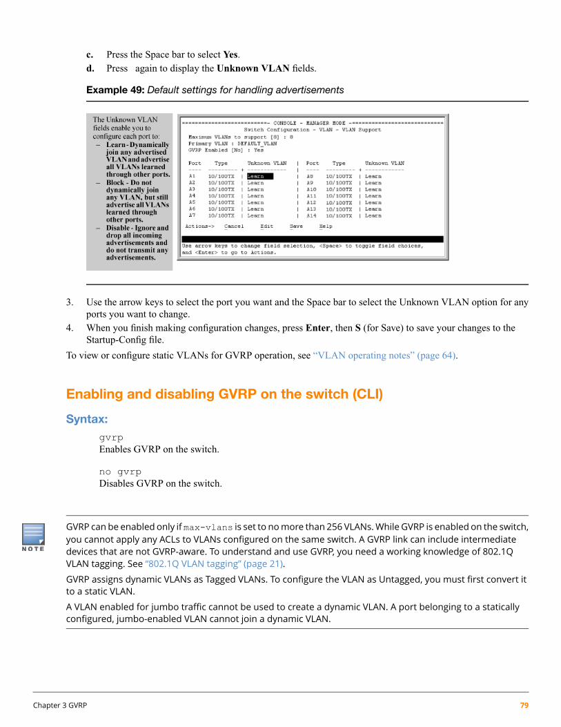
c. Press the Space bar to select Yes.d. Press again to display the Unknown VLAN fields.
Example 49: Default settings for handling advertisements
3. Use the arrow keys to select the port you want and the Space bar to select the Unknown VLAN option for anyports you want to change.
4. When you finish making configuration changes, press Enter, then S (for Save) to save your changes to theStartup-Config file.
To view or configure static VLANs for GVRP operation, see “VLAN operating notes” (page 64).
Enabling and disabling GVRP on the switch (CLI)
Syntax:gvrpEnables GVRP on the switch.
no gvrpDisables GVRP on the switch.
GVRP can be enabled only if max-vlans is set to nomore than 256 VLANs.While GVRP is enabled on the switch,you cannot apply any ACLs to VLANs configured on the same switch. A GVRP link can include intermediatedevices that are not GVRP-aware. To understand and use GVRP, you need a working knowledge of 802.1QVLAN tagging. See “802.1Q VLAN tagging” (page 21).
GVRP assigns dynamic VLANs as Tagged VLANs. To configure the VLAN as Untagged, you must first convert itto a static VLAN.
A VLAN enabled for jumbo traffic cannot be used to create a dynamic VLAN. A port belonging to a staticallyconfigured, jumbo-enabled VLAN cannot join a dynamic VLAN.
Chapter 3 GVRP 79
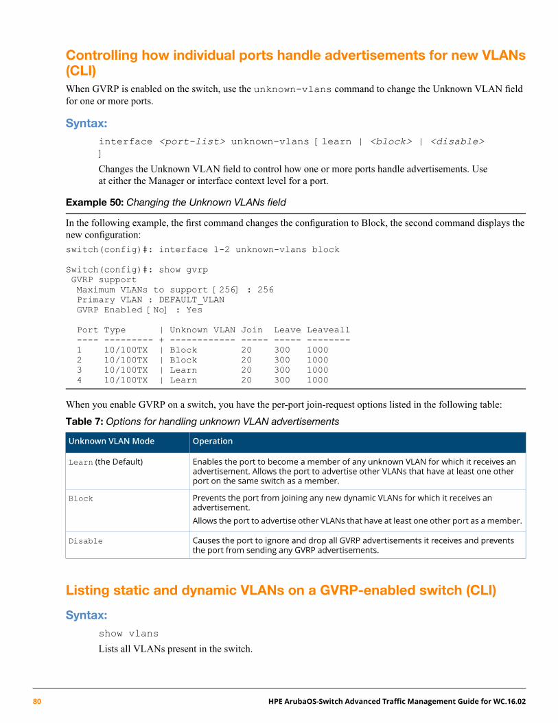
Controlling how individual ports handle advertisements for new VLANs(CLI)When GVRP is enabled on the switch, use the unknown-vlans command to change the Unknown VLAN fieldfor one or more ports.
Syntax:interface <port-list> unknown-vlans [learn | <block> | <disable>]
Changes the Unknown VLAN field to control how one or more ports handle advertisements. Useat either the Manager or interface context level for a port.
Example 50: Changing the Unknown VLANs field
In the following example, the first command changes the configuration to Block, the second command displays thenew configuration:
switch(config)#: interface 1-2 unknown-vlans block
Switch(config)#: show gvrpGVRP supportMaximum VLANs to support [256] : 256Primary VLAN : DEFAULT_VLANGVRP Enabled [No] : Yes
Port Type | Unknown VLAN Join Leave Leaveall---- --------- + ------------ ----- ----- --------1 10/100TX | Block 20 300 10002 10/100TX | Block 20 300 10003 10/100TX | Learn 20 300 10004 10/100TX | Learn 20 300 1000
When you enable GVRP on a switch, you have the per-port join-request options listed in the following table:
Table 7: Options for handling unknown VLAN advertisements
OperationUnknown VLAN Mode
Enables the port to become a member of any unknown VLAN for which it receives anadvertisement. Allows the port to advertise other VLANs that have at least one otherport on the same switch as a member.
Learn (the Default)
Prevents the port from joining any new dynamic VLANs for which it receives anadvertisement.
Block
Allows the port to advertise other VLANs that have at least one other port as a member.
Causes the port to ignore and drop all GVRP advertisements it receives and preventsthe port from sending any GVRP advertisements.
Disable
Listing static and dynamic VLANs on a GVRP-enabled switch (CLI)
Syntax:show vlans
Lists all VLANs present in the switch.
80 HPE ArubaOS-Switch Advanced Traffic Management Guide for WC.16.02

Example 51: Using the show vlans command
In the following illustration, switch B has one static VLAN (the default VLAN), with GVRP enabled and port 1configured to Learn for Unknown VLANs. Switch A has GVRP enabled and has three static VLANs: the defaultVLAN, VLAN-222 and VLAN-333. In this scenario, switch B will dynamically join VLAN-222 and VLAN-333:
The show vlans command lists the dynamic (and static) VLANs in switch B after it has learned and joinedVLAN-222 and VLAN-333.
Switch-B> show vlans
Status and Counters - VLAN Information
VLAN support : YesMaximum VLANs to support : 8Primary VLAN : DEFAULT_VLAN
802.1Q VLAN ID NAME Status-------------- ------------- ------1 DEFAULT_VLAN Static222 GVRP_222 Dynamic333 GVRP_333 Dynamic
Converting a Dynamic VLAN to a Static VLAN (CLI)If a port on the switch has joined a dynamic VLAN, you can use the following command to convert that dynamicVLAN to a static VLAN:
static <dynamic-vlan-id>
Example 52: Converting a dynamic VLAN 333 to a static VLAN
When converting a dynamic VLAN to a static VLAN as shown here, all ports on the switch are assigned to theVLAN in Auto mode.
switch(config)#: static 333
About GVRPGVRP (GARP VLAN Registration Protocol) is an application of GARP (Generic Attribute Registration Protocol.)It enables a switch to dynamically create 802.1Q-compliant VLANs on links with other devices running GVRP andautomatically create VLAN links between GVRP-aware devices. (A GVRP link can include intermediate devicesthat are not GVRP-aware.) This operation reduces the chance for errors in VLAN configurations by automatically
Chapter 3 GVRP 81

providing VID (VLAN ID) consistency across the network. After the switch creates a dynamic VLAN, the CLIstatic <vlan-id> command can be used to convert it to a static VLAN. GVRP can also be used to dynamicallyenable port membership in static VLANs configured on a switch.
GVRP uses GVRP BPDUs (GVRP Bridge Protocol Data Units) to advertise static VLANs; this a GVRP BPDU iscalled an advertisement. On a switch, advertisements are sent outbound from ports to the devices directly connectedto those ports.
GVRP operational rules
• A dynamic VLAN must be converted to a static VLAN before it can have an IP address.
• For the switches covered in this guide, GVRP can be enabled only if max-vlans is set to no more than 256VLANs.
• The total number of VLANs on the switch (static and dynamic combined) cannot exceed the current MaximumVLANs setting. For example, in the factory default state, the switch supports up to 256 VLANs. Any additionalVLANs advertised to the switch will not be added unless you first increase the Maximum VLANs setting. Inthe Menu interface, click on 2. Switch Configuration … | 8. VLAN Menu | 1. VLAN Support. In the globalconfig level of the CLI, use max-vlans.
• Converting a dynamic VLAN to a static VLAN and then executing the write memory command saves theVLAN in the startup-config file and makes it a permanent part of the switch's VLAN configuration.
• Within the same broadcast domain, a dynamic VLAN can pass through a device that is notGVRP-aware. Thisis because a half-duplex repeater, a hub, or a switch that is not GVRP-aware will flood the GVRP (multicast)advertisement packets out all ports.
• GVRP assigns dynamic VLANs as tagged VLANs. To configure the VLAN as untagged, convert it to a staticVLAN.
• Rebooting a switch on which a dynamic VLAN exists deletes that VLAN. However, the dynamic VLANreappears after the reboot if GVRP is enabled and the switch again receives advertisements for that VLANthrough a port configured to add dynamic VLANs.
• By receiving advertisements from other devices running GVRP, the switch learns of static VLANs on thoseother devices and dynamically (automatically) creates tagged VLANs on the links to the advertising devices.Similarly, the switch advertises its static VLANs to other GVRP-aware devices, as well as the dynamic VLANsthe switch has learned.
• A GVRP-enabled switch does not advertise any GVRP-learned VLANs out of the ports on which it originallylearned of those VLANs.
• While GVRP is enabled on the switch, you cannot apply any ACLs to VLANs configured on the same switch.
• A VLAN enabled for jumbo traffic cannot be used to create a dynamic VLAN; a port belonging to a staticallyconfigured, jumbo-enabled VLAN cannot join a dynamic VLAN.
Example of GVRP operation
In the following example, Tagged VLAN ports on switch A and switch C advertise VLANs 22 and 33 to ports onother GVRP-enabled switches that can dynamically join the VLANs.
82 HPE ArubaOS-Switch Advanced Traffic Management Guide for WC.16.02
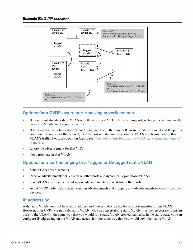
Example 53: GVRP operation
Options for a GVRP-aware port receiving advertisements
• If there is not already a static VLAN with the advertised VID on the receiving port, such a port can dynamicallycreate the VLAN and become a member.
• If the switch already has a static VLAN assignment with the same VID as in the advertisement and the port isconfigured to Auto for that VLAN, then the port will dynamically join the VLAN and begin moving thatVLAN's traffic. For more detail on Auto, see “Per-port options for dynamic VLAN advertising and joining”(page 84).
• Ignore the advertisement for that VID.
• Not participate in that VLAN.
Options for a port belonging to a Tagged or Untagged static VLAN
• Send VLAN advertisements
• Receive advertisements for VLANs on other ports and dynamically join those VLANs.
• Send VLAN advertisements but ignore advertisements received from other ports.
• Avoid GVRP participation by not sending advertisements and dropping any advertisements received from otherdevices.
IP addressingA dynamic VLAN does not have an IP address and moves traffic on the basis of port membership in VLANs.However, after GVRP creates a dynamic VLAN, you can convert it to a static VLAN. It is then necessary to assignports to the VLAN in the same way that you would for a static VLAN created manually. In the static state, you canconfigure IP addressing on the VLAN and access it in the same way that you would any other static VLAN.
Chapter 3 GVRP 83

Per-port options for handling GVRP "unknown VLANs"An "unknown VLAN" is a VLAN that the switch learns of by receiving an advertisement for that VLAN on a portthat is not already a member of that VLAN. If the port is configured to learn unknown VLANs, then the VLAN isdynamically created and the port becomes a tagged member of the VLAN.
Example 54: GVRP unknown VLAN settings
Suppose that in Example 53 (page 83), port 1 on switch A is connected to port 5 on switch C. Because switch Ahas VLAN 22 statically configured, while switch C does not have this VLAN statically configured (and does not"Forbid" VLAN 22 on port 5), VLAN 22 is handled as an "Unknown VLAN" on port 5 in switch C. Conversely, ifVLAN 22 was statically configured on switch C, but port 5 was not a member, port 5 would become a member whenadvertisements for VLAN 22 were received from switch A.
The CLI show gvrp command and the menu interface VLAN Support screen show a switch's current GVRPconfiguration, including the Unknown VLAN settings.
Per-port options for dynamic VLAN advertising and joining
Initiating advertisements
As described in the preceding section, to enable dynamic joins, GVRP must be enabled and a port must be configuredto Learn (the default). However, to send advertisements in your network, one or more static (Tagged, Untagged, orAuto) VLANs must be configured on one or more switches (with GVRP enabled), depending on your topology.
Enabling a port for dynamic joins
You can configure a port to dynamically join a static VLAN. The join will occur if that port subsequently receivesan advertisement for the static VLAN. This is done by using the Auto and Learn options described in Table 8(page 85).
84 HPE ArubaOS-Switch Advanced Traffic Management Guide for WC.16.02

Parameters for controlling VLAN propagation behavior
You can configure an individual port to actively or passively participate in dynamic VLAN propagation or to ignoredynamic VLAN (GVRP) operation. These options are controlled by the GVRP "Unknown VLAN" and the staticVLAN configuration parameters, as described in Table 8 (page 85).
Table 8: Controlling VLAN behavior on ports with static VLANs
Static VLAN Options—Per VLAN Specified on Each Port1Per-Port"UnknownVLAN"(GVRP)configuration
Port Activity: Forbid (Per VLAN)2Port Activity: Auto2 (Per VLAN)Port Activity: Tagged orUntagged (Per VLAN)2
The port:The port:The port:Learn (theDefault) ••• Will not become amember of
the specified VLAN.Will become a member ofspecified VLAN if it receivesadvertisements for specifiedVLAN from another device.
Belongs to specified VLAN.
• Advertises specified VLAN.• Will not advertise specified
VLAN.• Can become a member ofdynamic VLANs for which itreceives advertisements. • Will advertise specified VLAN. • Can become a member of
other dynamic VLANs forwhich it receivesadvertisements.
• Can become a member ofother, dynamic VLANs forwhich it receivesadvertisements.
• Advertises dynamic VLANsthat have at least one otherport (on the same switch) asa member. • Will advertise a dynamic VLAN
that has at least one otherport on the same switch as amember.
• Will advertise a dynamic VLANthat has at least one otherport (on the same switch) asa member.
The port:The port:The port:Block••• Will not become amember of
this VLAN.Will become a member ofspecified VLAN if it receivesadvertisements for this VLAN.
Belongs to the specified VLAN.
• Advertises this VLAN.• Will ignore GVRP PDUs.• Will not become amember of
newdynamic VLANs forwhichit receives advertisements.
• Will advertise this VLAN. • Will not join any dynamicVLANs.• Will not become amember of
newdynamic VLANs forwhichit receives advertisements.
• Will not advertise VLANs.• Will advertise dynamic VLANsthat have at least one otherport as a member. • Will advertise dynamic VLANs
that have at least one otherport (on the same switch) asa member.
The port:The port:The port:Disable••• Will not become amember of
this VLAN.Will not become amember ofthe specified VLAN.
Is a member of the specifiedVLAN.
• ••Will ignore GVRP PDUs. Will ignore GVRP PDUs.Will ignore GVRP PDUs.
•• •Will not join any dynamicVLANs.
Will not join any advertisedVLANs.
Will not join any dynamicVLANs.
••• Will not advertise VLANs.Will not advertise VLANs.Will not advertise VLANs.1 Each port of the switch must be a Tagged or Untagged member of at least one VLAN. Thus, any port configured for GVRP to Learn or Block
will generate and forward advertisements for static VLAN(s) configured on the switch and also for dynamic VLANs the switch learns on other
ports.2 To configure tagging, Auto, or Forbid, see “Configuring or changing static VLAN per-port settings (CLI)” (page 40) (for the CLI) or “Adding
or changing a VLAN port assignment (Menu)” (page 37) (for the menu).
As the preceding table indicates, when you enable GVRP, a port that has a Tagged or Untagged static VLAN hasthe option for both generating advertisements and dynamically joining other VLANs.
Chapter 3 GVRP 85

In Table 8 (page 85), the Unknown VLAN parameters are configured on a per-port basis using the CLI. TheTagged, Untagged, Auto, and Forbid options are configured per static VLAN on every port, using either themenu interface or the CLI.
Becausedynamic VLANsoperate as TaggedVLANs andbecause a taggedport ononedevice cannot communicatewith an untagged port on another device, Hewlett Packard Enterprise recommends that you use Tagged VLANsfor the static VLANs you will use to generate advertisements.
GVRP and VLAN access control
Advertisements and dynamic joins
When you enable GVRP on a switch, the default GVRP parameter settings allow all of the switch's ports to transmitand receive dynamic VLAN advertisements (GVRP advertisements) and to dynamically join VLANs.
Enabling GVRP:
• Allows a port to both advertise and join dynamic VLANs (Learn mode—the default).
• Allows a port to send VLAN advertisements, but not receive them from other devices; that is, the port cannotdynamically join a VLAN but other devices can dynamically join the VLANs it advertises (Block mode).
• Prevents a port from participating in GVRP operation (Disable mode).
Port-Leave from a dynamic VLAN
A dynamic VLAN continues to exist on a port for as long as the port receives its advertisements from another deviceconnected to that port, or until:
• Converting the VLAN to a static VLAN
• Reconfiguring the port to Block or Disable
• Disabling GVRP
• Rebooting the switch.
The time-to-live for dynamic VLANs is 10 seconds, if a port has not received an advertisement for an existingdynamic VLAN during that time, the port removes itself from that dynamic VLAN.
86 HPE ArubaOS-Switch Advanced Traffic Management Guide for WC.16.02

Chapter 4
Multiple VLAN Registration Protocol
Multiple VLAN Registration Protocol overviewMultiple VLAN Registration Protocol (MVRP) is a registration protocol defined by IEEE, which propagates VLANinformation dynamically across devices. It also enables devices to learn and automatically synchronize VLANconfiguration information, thereby reducing the configuration workload.
It is an enhanced version of GVRP and improves declaration efficiency. It allows a participant (port) to make orwithdraw declaration of attributes (VLANs). These declarations (or withdraws) are resulted in registration (or removalof registrations) with other switches in the network.
Salient features
• Complaint as per IEEE 802.1Q-2011(Clause 11.2).
• Supports conversion of dynamic VLAN to static VLAN.
• Supports propagation of radius assigned dynamic VLANs.
• Supports immediate registration and propagation of VLAN attributes during spanning tree topology changes.
• Supports registrar’s administrative control values such as normal, fixed, and forbid.
• Supports MVRP objects on the following standard MIBs:
IEEE8021-Q-BRIDGE-MIB (version 200810150000Z)◦◦ IEEE8021-BRIDGE-MIB (version 200810150000Z)
Supports otherMVRP objectswith the help of proprietaryMIB, HP-ICF-MVRP-MIB(hpicfMvrp.mib).
• Supports on both physical and LAG ports, which include the manual (HP trunk), static lacp, and dynamic lacptrunks.
• Supports High Availability hitless.
• Supports configuring MVRP using CLI and SNMP commands.
• Supports configurable timers — Join, Leave, Leave-All, and Periodic.
• Supports fast logging for important MVRP events and error conditions.
• Supports debug logging for all MVRP enabled ports.
• MVRP can be used to manage VLANs on dynamic trunk.
Supported Platforms
• Aruba 2920 Switch
• Aruba 2530 YA/YB Switch
• HPE Switch 2620
Chapter 4 Multiple VLAN Registration Protocol 87
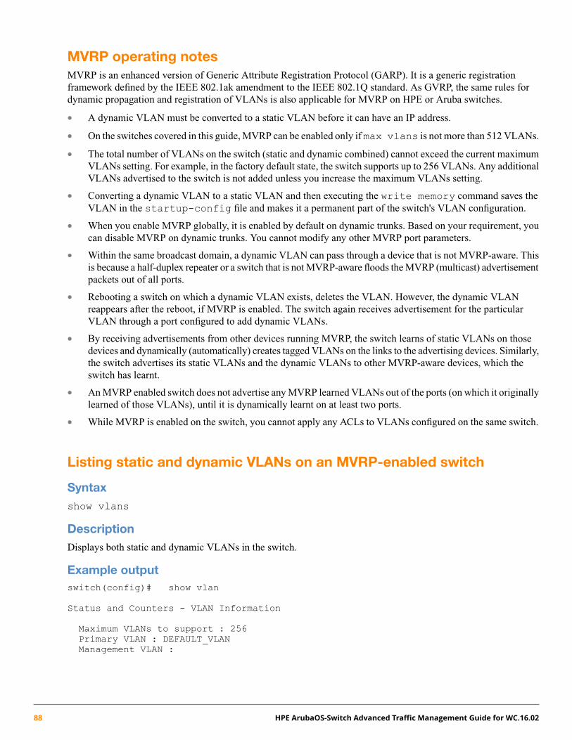
MVRP operating notesMVRP is an enhanced version of Generic Attribute Registration Protocol (GARP). It is a generic registrationframework defined by the IEEE 802.1ak amendment to the IEEE 802.1Q standard. As GVRP, the same rules fordynamic propagation and registration of VLANs is also applicable for MVRP on HPE or Aruba switches.
• A dynamic VLAN must be converted to a static VLAN before it can have an IP address.
• On the switches covered in this guide, MVRP can be enabled only if max vlans is not more than 512 VLANs.
• The total number of VLANs on the switch (static and dynamic combined) cannot exceed the current maximumVLANs setting. For example, in the factory default state, the switch supports up to 256 VLANs. Any additionalVLANs advertised to the switch is not added unless you increase the maximum VLANs setting.
• Converting a dynamic VLAN to a static VLAN and then executing the write memory command saves theVLAN in the startup-config file and makes it a permanent part of the switch's VLAN configuration.
• When you enable MVRP globally, it is enabled by default on dynamic trunks. Based on your requirement, youcan disable MVRP on dynamic trunks. You cannot modify any other MVRP port parameters.
• Within the same broadcast domain, a dynamic VLAN can pass through a device that is not MVRP-aware. Thisis because a half-duplex repeater or a switch that is not MVRP-aware floods the MVRP (multicast) advertisementpackets out of all ports.
• Rebooting a switch on which a dynamic VLAN exists, deletes the VLAN. However, the dynamic VLANreappears after the reboot, if MVRP is enabled. The switch again receives advertisement for the particularVLAN through a port configured to add dynamic VLANs.
• By receiving advertisements from other devices running MVRP, the switch learns of static VLANs on thosedevices and dynamically (automatically) creates tagged VLANs on the links to the advertising devices. Similarly,the switch advertises its static VLANs and the dynamic VLANs to other MVRP-aware devices, which theswitch has learnt.
• An MVRP enabled switch does not advertise any MVRP learned VLANs out of the ports (on which it originallylearned of those VLANs), until it is dynamically learnt on at least two ports.
• While MVRP is enabled on the switch, you cannot apply any ACLs to VLANs configured on the same switch.
Listing static and dynamic VLANs on an MVRP-enabled switch
Syntaxshow vlans
DescriptionDisplays both static and dynamic VLANs in the switch.
Example outputswitch(config)# show vlan
Status and Counters - VLAN Information
Maximum VLANs to support : 256Primary VLAN : DEFAULT_VLANManagement VLAN :
88 HPE ArubaOS-Switch Advanced Traffic Management Guide for WC.16.02

VLAN ID Name | Status Voice Jumbo------- -------------------------------- + ---------- ----- -----1 DEFAULT_VLAN | Port-based No No40 MVRP_40 | Dynamic
Converting a dynamic VLAN to a static VLAN
Syntaxstatic-vlan <dynamic-vlan-id>
DescriptionIf a port on the switch has joined a dynamic VLAN, use the command to convert dynamic VLAN to static VLANsin the switch.
Example outputswitch(config)# static-vlan 40switch(config)# show vlan
Status and Counters - VLAN Information
Maximum VLANs to support : 256Primary VLAN : DEFAULT_VLANManagement VLAN :
VLAN ID Name | Status Voice Jumbo------- -------------------------------- + ---------- ----- -----1 DEFAULT_VLAN | Port-based No No40 VLAN40 | Port-based No No
Viewing the current MVRP configuration on a switch
show mvrp
Syntax
show mvrp [config|state|statistics]
Description
Displays the MVRP settings and status.
Example outputswitch# show mvrpconfig Show the MVRP configuration for all ports.state Show the MVRP state.statistics Show MVRP statistics.
show mvrp config
Syntax
show mvrp config
Chapter 4 Multiple VLAN Registration Protocol 89

Description
Displays the MVRP configuration for all ports.
Example outputswitch# show mvrp config
Configuration and Status - MVRP
Global MVRP status : Disabled
Port Status Periodic Registration Join Leave LeaveAll PeriodicTimer Type Time Timer Timer Timer
------- -------- -------- ------------ ---- -------- -------- --------1 Disabled Enabled Normal 20 300 1000 1002 Disabled Enabled Normal 20 300 1000 1003 Disabled Enabled Normal 20 300 1000 100
show mvrp state
Syntax
show mvrp state <VLAN-ID> [<PORT-NUM>]
Description
Displays the MVRP state.
Parameters
VLAN-ID
Specify the MVRP state for VLAN ID.
PORT-NUM
Specify the port number on which MVRP is to be configured.
Example outputswitch(config)# show mvrp stateVLAN-ID Enter a VLAN identifier or the VLAN name if configured.switch(config)# show mvrp state 1[ethernet] PORT-NUMswitch(config)# show mvrp state 1
Configuration and Status - MVRP state for VLAN 1
Port VLAN Registrar Applicant ForbidState State Mode
-------- ----- --------- --------- ---------1 1 MT QA No
show mvrp statistics
Syntax
show MVRP statistics [<PORT-LIST>]
Description
Displays the MVRP statistics.
90 HPE ArubaOS-Switch Advanced Traffic Management Guide for WC.16.02
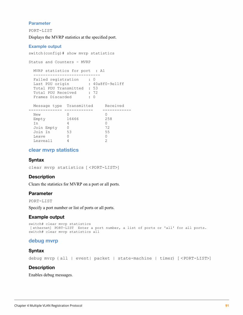
Parameter
PORT-LIST
Displays the MVRP statistics at the specified port.
Example outputswitch(config)# show mvrp statistics
Status and Counters - MVRP
MVRP statistics for port : A1----------------------------Failed registration : 0Last PDU origin : 40a8f0-9e11ffTotal PDU Transmitted : 53Total PDU Received : 72Frames Discarded : 0
Message type Transmitted Received-------------- ------------ ------------New 0 0Empty 16466 258In 4 0Join Empty 0 72Join In 53 55Leave 0 0Leaveall 4 2
clear mvrp statistics
Syntax
clear mvrp statistics [<PORT-LIST>]
Description
Clears the statistics for MVRP on a port or all ports.
Parameter
PORT-LIST
Specify a port number or list of ports or all ports.
Example outputswitch# clear mvrp statistics[ethernet] PORT-LIST Enter a port number, a list of ports or 'all' for all ports.switch# clear mvrp statistics all
debug mvrp
Syntax
debug mvrp {all | event| packet | state-machine | timer} [<PORT-LIST>]
Description
Enables debug messages.
Chapter 4 Multiple VLAN Registration Protocol 91
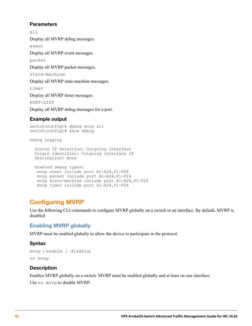
Parameters
all
Display all MVRP debug messages.
event
Display all MVRP event messages.
packet
Display all MVRP packet messages.
state-machine
Display all MVRP state-machine messages.
timer
Display all MVRP timer messages.
PORT-LIST
Display all MVRP debug messages for a port.
Example outputswitch(config)# debug mvrp allswitch(config)# show debug
Debug Logging
Source IP Selection: Outgoing InterfaceOrigin identifier: Outgoing Interface IPDestination: None
Enabled debug types:mvrp event include port A1-A24,F1-F24mvrp packet include port A1-A24,F1-F24mvrp state-machine include port A1-A24,F1-F24mvrp timer include port A1-A24,F1-F24
Configuring MVRPUse the following CLI commands to configure MVRP globally on a switch or an interface. By default, MVRP isdisabled.
Enabling MVRP globallyMVRP must be enabled globally to allow the device to participate in the protocol.
Syntax
mvrp {enable | disable}
no mvrp
Description
Enables MVRP globally on a switch. MVRP must be enabled globally and at least on one interface.
Use no mvrp to disable MVRP.
92 HPE ArubaOS-Switch Advanced Traffic Management Guide for WC.16.02
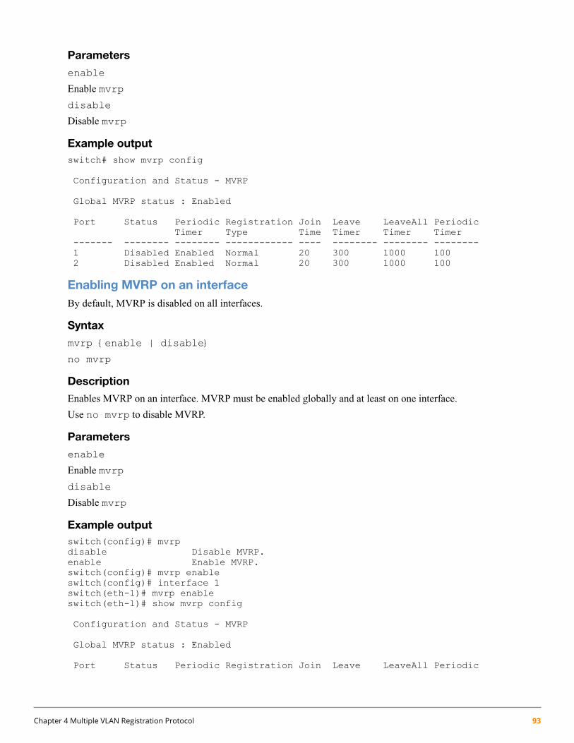
Parameters
enable
Enable mvrp
disable
Disable mvrp
Example outputswitch# show mvrp config
Configuration and Status - MVRP
Global MVRP status : Enabled
Port Status Periodic Registration Join Leave LeaveAll PeriodicTimer Type Time Timer Timer Timer
------- -------- -------- ------------ ---- -------- -------- --------1 Disabled Enabled Normal 20 300 1000 1002 Disabled Enabled Normal 20 300 1000 100
Enabling MVRP on an interfaceBy default, MVRP is disabled on all interfaces.
Syntax
mvrp {enable | disable}
no mvrp
Description
Enables MVRP on an interface. MVRP must be enabled globally and at least on one interface.
Use no mvrp to disable MVRP.
Parameters
enable
Enable mvrp
disable
Disable mvrp
Example outputswitch(config)# mvrpdisable Disable MVRP.enable Enable MVRP.switch(config)# mvrp enableswitch(config)# interface 1switch(eth-1)# mvrp enableswitch(eth-1)# show mvrp config
Configuration and Status - MVRP
Global MVRP status : Enabled
Port Status Periodic Registration Join Leave LeaveAll Periodic
Chapter 4 Multiple VLAN Registration Protocol 93
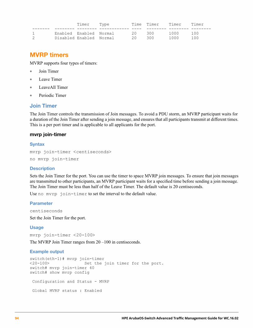
Timer Type Time Timer Timer Timer------- -------- -------- ------------ ---- -------- -------- --------1 Enabled Enabled Normal 20 300 1000 1002 Disabled Enabled Normal 20 300 1000 100
MVRP timersMVRP supports four types of timers:
• Join Timer
• Leave Timer
• LeaveAll Timer
• Periodic Timer
Join TimerThe Join Timer controls the transmission of Join messages. To avoid a PDU storm, an MVRP participant waits fora duration of the Join Timer after sending a join message, and ensures that all participants transmit at different times.This is a per port timer and is applicable to all applicants for the port.
mvrp join-timer
Syntax
mvrp join-timer <centiseconds>
no mvrp join-timer
Description
Sets the Join Timer for the port. You can use the timer to space MVRP join messages. To ensure that join messagesare transmitted to other participants, an MVRP participant waits for a specified time before sending a join message.The Join Timer must be less than half of the Leave Timer. The default value is 20 centiseconds.
Use no mvrp join-timer to set the interval to the default value.
Parameter
centiseconds
Set the Join Timer for the port.
Usage
mvrp join-timer <20-100>
The MVRP Join Timer ranges from 20 –100 in centiseconds.
Example outputswitch(eth-1)# mvrp join-timer<20-100> Set the join timer for the port.switch# mvrp join-timer 40switch# show mvrp config
Configuration and Status - MVRP
Global MVRP status : Enabled
94 HPE ArubaOS-Switch Advanced Traffic Management Guide for WC.16.02

Port Status Periodic Registration Join Leave LeaveAll PeriodicTimer Type Time Timer Timer Timer
------- -------- -------- ------------ ---- -------- -------- --------1 Enabled Enabled Normal 40 300 1000 1002 Disabled Enabled Normal 20 300 1000 1003 Disabled Enabled Normal 20 300 1000 100
Leave TimerThe Leave Timer controls the time duration for which the Registrar state machine waits in the LV state beforechanging to the MT state. The Leave Timer is started only when a leave message is received by the applicant state.The attribute is deregistered, if there are requests to join before the expiry of the Leave Timer. This is a per porttimer and is applicable to all registrars for the port.
mvrp leave-timer
Syntax
mvrp leave-timer <centiseconds>
no mvrp leave-timer
Description
The Leave Timer must be at least twice the Join Timer and must be less than the LeaveAll Timer. The default valueis 300 centiseconds.
Use no mvrp leave-timer to set the interval to the default value.
Parameter
centiseconds
Set the Leave Timer for the port.
Usage
mvrp leave-timer <40-1000000>
The MVRP Leave Timer ranges from 40 –1000000 in centiseconds.
Example outputswitch(eth-1)# mvrp leave-timer<40-1000000> Set the leave timer for the port.switch(eth-1)# mvrp leave-timer 500switch(eth-1)# show mvrp config
Configuration and Status - MVRP
Global MVRP status : Enabled
Port Status Periodic Registration Join Leave LeaveAll PeriodicTimer Type Time Timer Timer Timer
------- -------- -------- ------------ ---- -------- -------- --------1 Enabled Enabled Normal 40 500 1000 1002 Disabled Enabled Normal 20 300 1000 1003 Disabled Enabled Normal 20 300 1000 100
Chapter 4 Multiple VLAN Registration Protocol 95
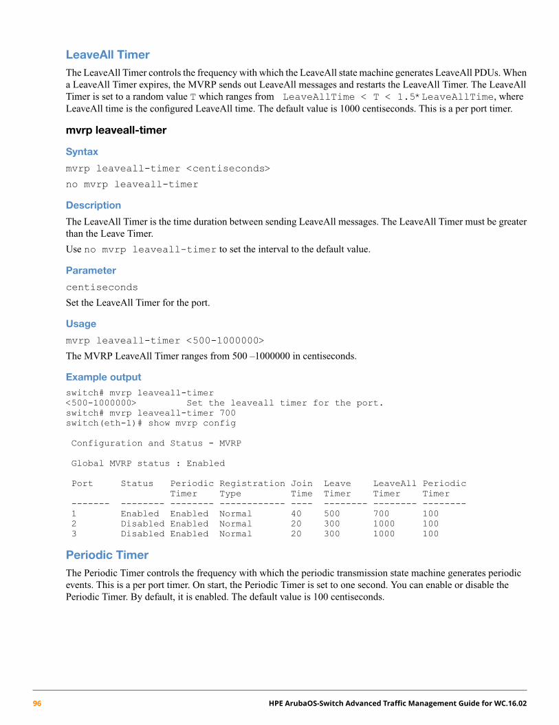
LeaveAll TimerThe LeaveAll Timer controls the frequency with which the LeaveAll state machine generates LeaveAll PDUs. Whena LeaveAll Timer expires, the MVRP sends out LeaveAll messages and restarts the LeaveAll Timer. The LeaveAllTimer is set to a random value T which ranges from LeaveAllTime < T < 1.5*LeaveAllTime, whereLeaveAll time is the configured LeaveAll time. The default value is 1000 centiseconds. This is a per port timer.
mvrp leaveall-timer
Syntax
mvrp leaveall-timer <centiseconds>
no mvrp leaveall-timer
Description
The LeaveAll Timer is the time duration between sending LeaveAll messages. The LeaveAll Timer must be greaterthan the Leave Timer.
Use no mvrp leaveall-timer to set the interval to the default value.
Parameter
centiseconds
Set the LeaveAll Timer for the port.
Usage
mvrp leaveall-timer <500-1000000>
The MVRP LeaveAll Timer ranges from 500 –1000000 in centiseconds.
Example outputswitch# mvrp leaveall-timer<500-1000000> Set the leaveall timer for the port.switch# mvrp leaveall-timer 700switch(eth-1)# show mvrp config
Configuration and Status - MVRP
Global MVRP status : Enabled
Port Status Periodic Registration Join Leave LeaveAll PeriodicTimer Type Time Timer Timer Timer
------- -------- -------- ------------ ---- -------- -------- --------1 Enabled Enabled Normal 40 500 700 1002 Disabled Enabled Normal 20 300 1000 1003 Disabled Enabled Normal 20 300 1000 100
Periodic TimerThe Periodic Timer controls the frequency with which the periodic transmission state machine generates periodicevents. This is a per port timer. On start, the Periodic Timer is set to one second. You can enable or disable thePeriodic Timer. By default, it is enabled. The default value is 100 centiseconds.
96 HPE ArubaOS-Switch Advanced Traffic Management Guide for WC.16.02
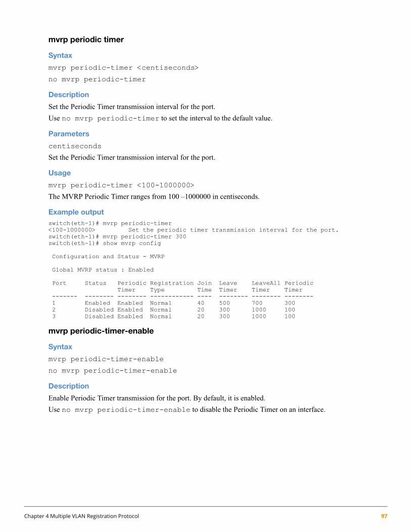
mvrp periodic timer
Syntax
mvrp periodic-timer <centiseconds>
no mvrp periodic-timer
Description
Set the Periodic Timer transmission interval for the port.
Use no mvrp periodic-timer to set the interval to the default value.
Parameters
centiseconds
Set the Periodic Timer transmission interval for the port.
Usage
mvrp periodic-timer <100-1000000>
The MVRP Periodic Timer ranges from 100 –1000000 in centiseconds.
Example outputswitch(eth-1)# mvrp periodic-timer<100-1000000> Set the periodic timer transmission interval for the port.switch(eth-1)# mvrp periodic-timer 300switch(eth-1)# show mvrp config
Configuration and Status - MVRP
Global MVRP status : Enabled
Port Status Periodic Registration Join Leave LeaveAll PeriodicTimer Type Time Timer Timer Timer
------- -------- -------- ------------ ---- -------- -------- --------1 Enabled Enabled Normal 40 500 700 3002 Disabled Enabled Normal 20 300 1000 1003 Disabled Enabled Normal 20 300 1000 100
mvrp periodic-timer-enable
Syntax
mvrp periodic-timer-enable
no mvrp periodic-timer-enable
Description
Enable Periodic Timer transmission for the port. By default, it is enabled.
Use no mvrp periodic-timer-enable to disable the Periodic Timer on an interface.
Chapter 4 Multiple VLAN Registration Protocol 97
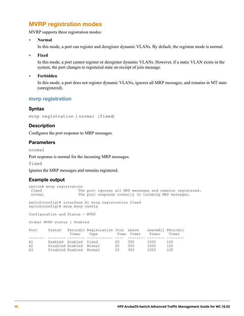
MVRP registration modesMVRP supports three registration modes:
• Normal
In this mode, a port can register and deregister dynamic VLANs. By default, the registrar mode is normal.
• Fixed
In this mode, a port cannot register or deregister dynamic VLANs. However, if a static VLAN exists in thesystem, the port changes to registered state on receipt of join message.
• Forbidden
In this mode, a port does not register dynamic VLANs, ignores all MRP messages, and remains in MT state(unregistered).
mvrp registration
Syntax
mvrp registration {normal |fixed}
Description
Configures the port response to MRP messages.
Parameters
normal
Port response is normal for the incoming MRP messages.
fixed
Ignores the MRP messages and remains registered.
Example outputswitch# mvrp registrationfixed The port ignores all MRP messages and remains registered.normal The port responds normally to incoming MRP messages.
switch(config)# interface A1 mvrp registration fixedswitch(config)# show mvrp config
Configuration and Status - MVRP
Global MVRP status : Enabled
Port Status Periodic Registration Join Leave LeaveAll PeriodicTimer Type Time Timer Timer Timer
------- -------- -------- ------------ ---- -------- -------- --------A1 Enabled Enabled Fixed 20 300 1000 100A2 Disabled Enabled Normal 20 300 1000 100A3 Disabled Enabled Normal 20 300 1000 100
98 HPE ArubaOS-Switch Advanced Traffic Management Guide for WC.16.02
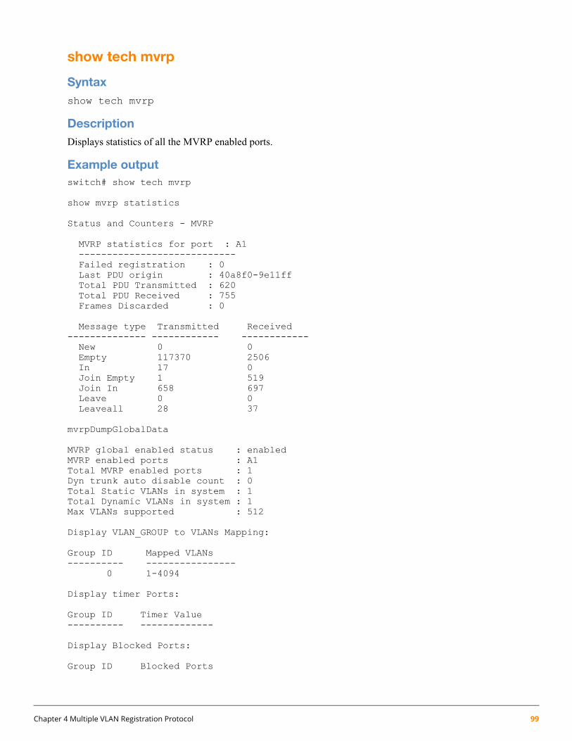
show tech mvrp
Syntaxshow tech mvrp
DescriptionDisplays statistics of all the MVRP enabled ports.
Example outputswitch# show tech mvrp
show mvrp statistics
Status and Counters - MVRP
MVRP statistics for port : A1----------------------------Failed registration : 0Last PDU origin : 40a8f0-9e11ffTotal PDU Transmitted : 620Total PDU Received : 755Frames Discarded : 0
Message type Transmitted Received-------------- ------------ ------------New 0 0Empty 117370 2506In 17 0Join Empty 1 519Join In 658 697Leave 0 0Leaveall 28 37
mvrpDumpGlobalData
MVRP global enabled status : enabledMVRP enabled ports : A1Total MVRP enabled ports : 1Dyn trunk auto disable count : 0Total Static VLANs in system : 1Total Dynamic VLANs in system : 1Max VLANs supported : 512
Display VLAN_GROUP to VLANs Mapping:
Group ID Mapped VLANs---------- ----------------
0 1-4094
Display timer Ports:
Group ID Timer Value---------- -------------
Display Blocked Ports:
Group ID Blocked Ports
Chapter 4 Multiple VLAN Registration Protocol 99
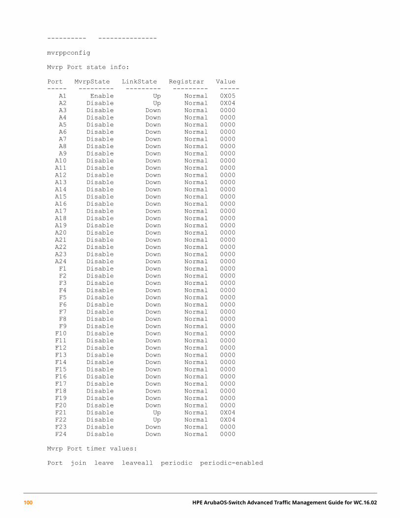
---------- ---------------
mvrppconfig
Mvrp Port state info:
Port MvrpState LinkState Registrar Value----- --------- --------- --------- -----
A1 Enable Up Normal 0X05A2 Disable Up Normal 0X04A3 Disable Down Normal 0000A4 Disable Down Normal 0000A5 Disable Down Normal 0000A6 Disable Down Normal 0000A7 Disable Down Normal 0000A8 Disable Down Normal 0000A9 Disable Down Normal 0000A10 Disable Down Normal 0000A11 Disable Down Normal 0000A12 Disable Down Normal 0000A13 Disable Down Normal 0000A14 Disable Down Normal 0000A15 Disable Down Normal 0000A16 Disable Down Normal 0000A17 Disable Down Normal 0000A18 Disable Down Normal 0000A19 Disable Down Normal 0000A20 Disable Down Normal 0000A21 Disable Down Normal 0000A22 Disable Down Normal 0000A23 Disable Down Normal 0000A24 Disable Down Normal 0000F1 Disable Down Normal 0000F2 Disable Down Normal 0000F3 Disable Down Normal 0000F4 Disable Down Normal 0000F5 Disable Down Normal 0000F6 Disable Down Normal 0000F7 Disable Down Normal 0000F8 Disable Down Normal 0000F9 Disable Down Normal 0000F10 Disable Down Normal 0000F11 Disable Down Normal 0000F12 Disable Down Normal 0000F13 Disable Down Normal 0000F14 Disable Down Normal 0000F15 Disable Down Normal 0000F16 Disable Down Normal 0000F17 Disable Down Normal 0000F18 Disable Down Normal 0000F19 Disable Down Normal 0000F20 Disable Down Normal 0000F21 Disable Up Normal 0X04F22 Disable Up Normal 0X04F23 Disable Down Normal 0000F24 Disable Down Normal 0000
Mvrp Port timer values:
Port join leave leaveall periodic periodic-enabled
100 HPE ArubaOS-Switch Advanced Traffic Management Guide for WC.16.02

----- ---- ----- -------- -------- ----------------A1 20 300 1000 100 enabledA2 20 300 1000 100 enabledA3 20 300 1000 100 enabledA4 20 300 1000 100 enabledA5 20 300 1000 100 enabledA6 20 300 1000 100 enabledA7 20 300 1000 100 enabledA8 20 300 1000 100 enabledA9 20 300 1000 100 enabledA10 20 300 1000 100 enabledA11 20 300 1000 100 enabledA12 20 300 1000 100 enabledA13 20 300 1000 100 enabledA14 20 300 1000 100 enabledA15 20 300 1000 100 enabledA16 20 300 1000 100 enabledA17 20 300 1000 100 enabledA18 20 300 1000 100 enabledA19 20 300 1000 100 enabledA20 20 300 1000 100 enabledA21 20 300 1000 100 enabledA22 20 300 1000 100 enabledA23 20 300 1000 100 enabledA24 20 300 1000 100 enabledF1 20 300 1000 100 enabledF2 20 300 1000 100 enabledF3 20 300 1000 100 enabledF4 20 300 1000 100 enabledF5 20 300 1000 100 enabledF6 20 300 1000 100 enabledF7 20 300 1000 100 enabledF8 20 300 1000 100 enabledF9 20 300 1000 100 enabledF10 20 300 1000 100 enabledF11 20 300 1000 100 enabledF12 20 300 1000 100 enabledF13 20 300 1000 100 enabledF14 20 300 1000 100 enabledF15 20 300 1000 100 enabledF16 20 300 1000 100 enabledF17 20 300 1000 100 enabledF18 20 300 1000 100 enabledF19 20 300 1000 100 enabledF20 20 300 1000 100 enabledF21 20 300 1000 100 enabledF22 20 300 1000 100 enabledF23 20 300 1000 100 enabledF24 20 300 1000 100 enabled
mvrpmapringShow
Mvrp list info:-------------------------Port A1 : connected
Mvrp Map Count Info:
Vlan Vid Reg-Count----- ----- ----------
Chapter 4 Multiple VLAN Registration Protocol 101
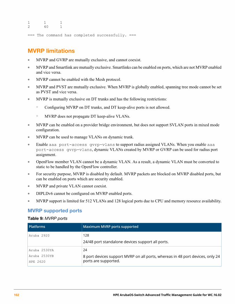
1 1 12 40 1
=== The command has completed successfully. ===
MVRP limitations• MVRP and GVRP are mutually exclusive, and cannot coexist.
• MVRP and Smartlink are mutually exclusive. Smartlinks can be enabled on ports, which are not MVRP enabledand vice versa.
• MVRP cannot be enabled with the Mesh protocol.
• MVRP and PVST are mutually exclusive. When MVRP is globally enabled, spanning tree mode cannot be setas PVST and vice versa.
• MVRP is mutually exclusive on DT trunks and has the following restrictions:
Configuring MVRP on DT trunks, and DT keep-alive ports is not allowed.◦◦ MVRP does not propagate DT keep-alive VLANs.
• MVRP can be enabled on a provider bridge environment, but does not support SVLAN ports in mixed modeconfiguration.
• MVRP can be used to manage VLANs on dynamic trunk.
• Enable aaa port-access gvrp-vlans to support radius assigned VLANs. When you enable aaaport-access gvrp-vlans, dynamic VLANs created by MVRP or GVRP can be used for radius portassignment.
• OpenFlow member VLAN cannot be a dynamic VLAN. As a result, a dynamic VLAN must be converted tostatic to be handled by the OpenFlow controller.
• For security purpose, MVRP is disabled by default. MVRP packets are blocked on MVRP disabled ports, butcan be enabled on ports which are security enabled.
• MVRP and private VLAN cannot coexist.
• DIPLDv6 cannot be configured on MVRP enabled ports.
• MVRP support is limited for 512 VLANs and 128 logical ports due to CPU and memory resource availability.
MVRP supported ports
Table 9: MVRP ports
MaximumMVRP ports supportedPlatforms
128
24/48 port standalone devices support all ports.
Aruba 2920
24
8 port devices support MVRP on all ports, whereas in 48 port devices, only 24ports are supported.
Aruba 2530YA
Aruba 2530YB
HPE 2620
102 HPE ArubaOS-Switch Advanced Traffic Management Guide for WC.16.02

MVRP supported VLANs
Table 10: MVRP supported VLANs
Maximum portsMaximumMSTP instanceMaximum VLANSPlatforms
12816512Aruba 2920
2416512Aruba 2530YA
2416512Aruba 2530YB
2416512HPE 2620
MVRP statisticsThe MVRP statistics generated using show mvrp statistics, records any registration failures, tracks MACaddresses to derive statistics.
• Registration failure
Maintains the count of registration requests received, but fails due to MVRP limitation.
• Peer tracking
Records the MAC address of MVRP PDU, which has caused the recent state change for the registrar machine.A maximum of one MAC address per port of the originator switch is stored.
• PDU event statistics
Collects the data on numbers of events (join, leave, and so on) transmitted and received.
More Information“show mvrp statistics” (page 90)
Chapter 4 Multiple VLAN Registration Protocol 103
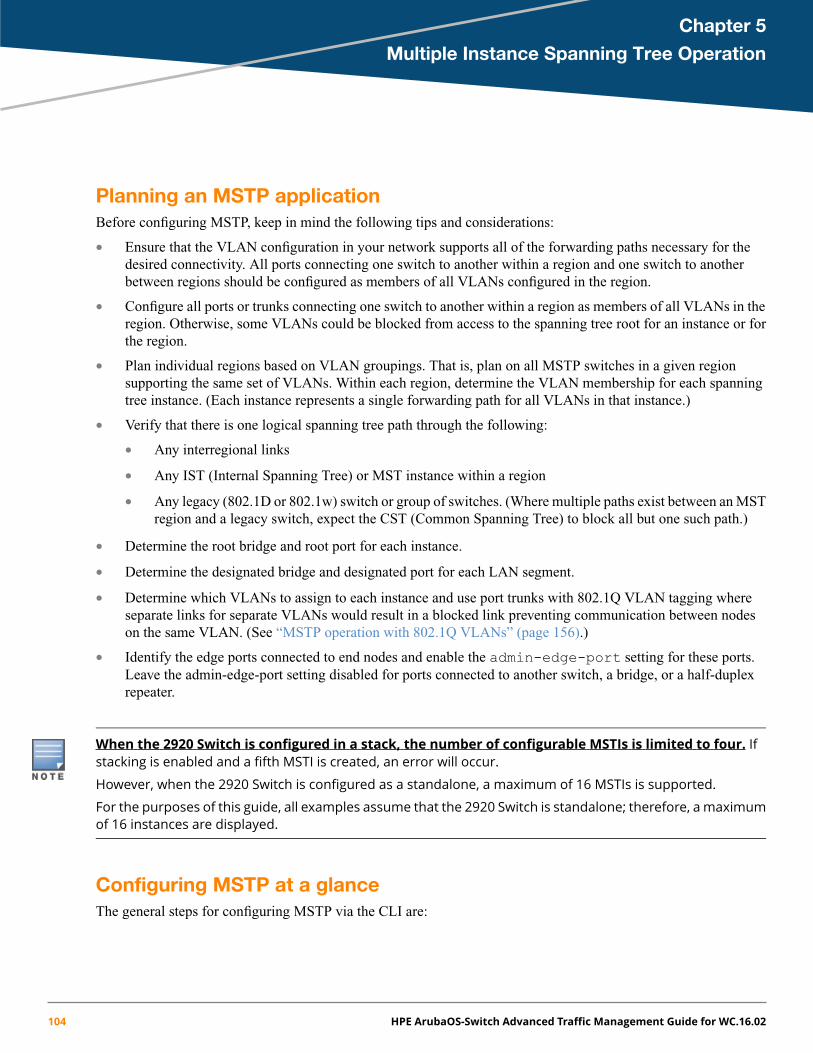
Chapter 5
Multiple Instance Spanning Tree Operation
Planning an MSTP applicationBefore configuring MSTP, keep in mind the following tips and considerations:
• Ensure that the VLAN configuration in your network supports all of the forwarding paths necessary for thedesired connectivity. All ports connecting one switch to another within a region and one switch to anotherbetween regions should be configured as members of all VLANs configured in the region.
• Configure all ports or trunks connecting one switch to another within a region as members of all VLANs in theregion. Otherwise, some VLANs could be blocked from access to the spanning tree root for an instance or forthe region.
• Plan individual regions based on VLAN groupings. That is, plan on all MSTP switches in a given regionsupporting the same set of VLANs. Within each region, determine the VLAN membership for each spanningtree instance. (Each instance represents a single forwarding path for all VLANs in that instance.)
• Verify that there is one logical spanning tree path through the following:
Any interregional links•
• Any IST (Internal Spanning Tree) or MST instance within a region
• Any legacy (802.1D or 802.1w) switch or group of switches. (Where multiple paths exist between an MSTregion and a legacy switch, expect the CST (Common Spanning Tree) to block all but one such path.)
• Determine the root bridge and root port for each instance.
• Determine the designated bridge and designated port for each LAN segment.
• Determine which VLANs to assign to each instance and use port trunks with 802.1Q VLAN tagging whereseparate links for separate VLANs would result in a blocked link preventing communication between nodeson the same VLAN. (See “MSTP operation with 802.1Q VLANs” (page 156).)
• Identify the edge ports connected to end nodes and enable the admin-edge-port setting for these ports.Leave the admin-edge-port setting disabled for ports connected to another switch, a bridge, or a half-duplexrepeater.
When the 2920 Switch is configured in a stack, the number of configurable MSTIs is limited to four. Ifstacking is enabled and a fifth MSTI is created, an error will occur.
However, when the 2920 Switch is configured as a standalone, a maximum of 16 MSTIs is supported.
For the purposes of this guide, all examples assume that the 2920 Switch is standalone; therefore, a maximumof 16 instances are displayed.
Configuring MSTP at a glanceThe general steps for configuring MSTP via the CLI are:
104 HPE ArubaOS-Switch Advanced Traffic Management Guide for WC.16.02
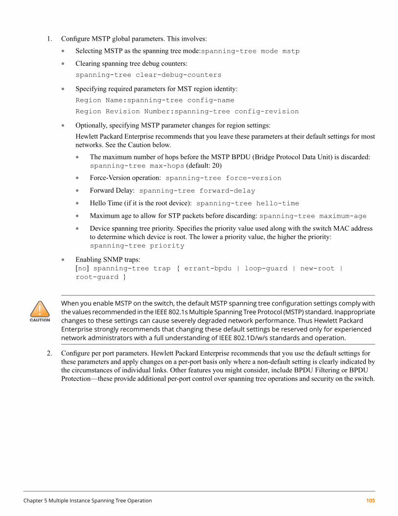
1. Configure MSTP global parameters. This involves:
• Selecting MSTP as the spanning tree mode:spanning-tree mode mstp
• Clearing spanning tree debug counters:
spanning-tree clear-debug-counters
• Specifying required parameters for MST region identity:
Region Name:spanning-tree config-name
Region Revision Number:spanning-tree config-revision
• Optionally, specifying MSTP parameter changes for region settings:
Hewlett Packard Enterprise recommends that you leave these parameters at their default settings for mostnetworks. See the Caution below.
• The maximum number of hops before the MSTP BPDU (Bridge Protocol Data Unit) is discarded:spanning-tree max-hops (default: 20)
• Force-Version operation: spanning-tree force-version
• Forward Delay: spanning-tree forward-delay
• Hello Time (if it is the root device): spanning-tree hello-time
• Maximum age to allow for STP packets before discarding: spanning-tree maximum-age
• Device spanning tree priority. Specifies the priority value used along with the switch MAC addressto determine which device is root. The lower a priority value, the higher the priority:spanning-tree priority
• Enabling SNMP traps:[no] spanning-tree trap { errant-bpdu | loop-guard | new-root |root-guard }
When you enable MSTP on the switch, the default MSTP spanning tree configuration settings comply withthe values recommended in the IEEE 802.1sMultiple Spanning Tree Protocol (MSTP) standard. Inappropriatechanges to these settings can cause severely degraded network performance. Thus Hewlett PackardEnterprise strongly recommends that changing these default settings be reserved only for experiencednetwork administrators with a full understanding of IEEE 802.1D/w/s standards and operation.
2. Configure per port parameters. Hewlett Packard Enterprise recommends that you use the default settings forthese parameters and apply changes on a per-port basis only where a non-default setting is clearly indicated bythe circumstances of individual links. Other features you might consider, include BPDU Filtering or BPDUProtection—these provide additional per-port control over spanning tree operations and security on the switch.
Chapter 5 Multiple Instance Spanning Tree Operation 105

3. Configure MST instances. Configure one instance for each VLAN group that you want to operate as an activetopology within the region to which the switch belongs. When you create the instance, you must include aminimum of one VID. You can add more VIDs later if desired. Use the following command:
spanning-tree instance <n> vlan <vid>
To move a VLAN from one instance to another, first use no spanning-tree instance <n> vlan<vid> to unmap the VLAN from the current instance, then add the VLAN to the other instance. (While theVLAN is unmapped from an MSTI, it is associated with the region's IST instance.)
4. Configure the priority for each instance with the following command: spanning-tree instance <n>priority <n>
5. Configure MST instance port parameters. Hewlett Packard Enterprise recommends that you apply changes ona per-port basis only where a non-default setting is clearly indicated by the circumstances of individual links.For example, you might want to set the path cost value for the ist or for the ports used by a specific MSTinstance. Use the following command:
spanning-tree instance <ist | 1..4 port-list> path-cost [<auto> |<1..200000000>]
Alternatively, leaving this setting at the default (auto) allows the switch to calculate the path-cost from the linkspeed.
6. Enable spanning tree operation on the switch with the spanning-tree command.
Configuring MSTP operation mode and global settingsThe commands in this section apply at the switch (global) level. For configuring spanning tree settings on individualports, see “Configuring MSTP per-port parameters” (page 111).
Selecting MSTP as the spanning tree mode
Syntax:
spanning-tree mode mstp
Specifies that spanning tree will run in MSTP mode.
Clearing spanning tree debug counters
Syntax:
spanning-tree clear-debug-counters
Clears spanning tree debug counters.
Resetting the configuration name of the MST region in which a switch resides
Syntax:
[no] spanning-tree config-name <ascii-string>
Resets the configuration name of the MST region in which the switch resides. This name can includeup to 32 nonblank characters and is case-sensitive. On all switches within a given MST region, theconfiguration names must be identical. For more than one MSTP switch in the same MST region,the identical region name must be configured on all such switches. If the default configuration nameis retained on a switch, it cannot exist in the same MST region with another switch.
106 HPE ArubaOS-Switch Advanced Traffic Management Guide for WC.16.02

The default name is a text string using the hexadecimal representation of the switch's MAC address.
The no form of the command overwrites the currently configured name with the default name.
This option is available only when the switch is configured for MSTP operation. There is nodefined limit on the number of regions you can configure.
Designating the revision number of the MST region for a switch
Syntax:
spanning-tree config-revision <revision-number>
Configures the revision number designated for the MST region in which you want the switch toreside. This setting must be the same for all switches residing in the same region. Use this settingto differentiate between region configurations in situations such as the following:
• Changing configuration settings within a region where you want to track the configurationversions you use
• Creating a new region from a subset of switches in a current region and want to maintain thesame region name.
• Using the pending option to maintain two different configuration options for the samephysical region.
This setting must be the same for all MSTP switches in the same MST region.
Range: 0 - 65535
Default: 0
This option is available only when the switch is configured for MSTP operation.
Setting the spanning tree compatibility mode
Syntax:
spanning-tree force-version [ stp-compatible | rstp-operation |mstp-operation ]
Sets the spanning tree compatibility mode. This command forces the switch to emulate behavior ofearlier versions of spanning tree protocol, or return to MSTP behavior. The command is useful intest or debug applications and removes the need to reconfigure the switch for temporary changesin spanning tree operation.
stp-compatible The switch applies 802.1D STP operation on all ports.
rstp-operation The switch applies 802.1w operation on all ports except those ports whereit detects a system using 802.1D Spanning Tree. RSTP is Rapid SpanningTree Protocol.
mstp-operation The switch applies 802.1s MSTP operation on all ports where compatibilitywith 802.1D or 802.1w spanning tree protocols is not required.
Chapter 5 Multiple Instance Spanning Tree Operation 107

Even when mstp-operation is selected, if the switch detects an 802.1D BPDU or an 802.1wBPDU on a port, it communicates with the device linked to that port using STP or RSTP BPDUpackets. Also, if errors are encountered as described in “ConfiguringMSTP at a glance” (page 104),setting force-version to stp-compatible forces the MSTP switch to communicate out allports using operations that are compatible with IEEE 802.1D STP.
When using MSTP rapid state transitions
Under some circumstances, the rapid state transitions employed by MSTP can increase therates of frame duplication and misordering in the switched LAN. To allow MSTP switches tosupport applications and protocols thatmay be sensitive to frame duplication andmisordering,setting the Force Protocol Version (force-version) parameter to stp-compatible allowsMSTP to operate with rapid transitions disabled. The value of this parameter applies to all portson the switch.
Setting the time interval between listening, learning, and forwarding states
Syntax:
spanning-tree forward-delay
Sets the time that the switch waits between transitioning from listening to learning and from learningto forwarding states.
Range: 4 - 30
Default: 15 seconds
Setting spanning tree to operate in 802. ID legacy mode
Syntax:
[no] spanning-tree legacy-mode
Forces spanning tree to operate in legacy (802.!D) mode.
Default: MSTP-operation.
The no form of this command returns the switch to the default 802.1s native mode (MSTP-operation)
Syntax:
spanning-tree legacy-path-cost
Setting spanning tree to operate with 802. ID legacy path cost values
Syntax:
Forces spanning tree to operate with legacy (802.!D) path cost values.
Default: 802.1t.
The no form of the command returns the switch to the default 802.1t (not legacy) path cost values.
Specifying the time interval between BPDU transmissions
Syntax:
spanning-tree hello-time <1..10>
108 HPE ArubaOS-Switch Advanced Traffic Management Guide for WC.16.02
If MSTP is running and the switch is operating as the CIST (Common and Internal Spanning Tree)root for your network, this command specifies the time in seconds between transmissions of BPDUsfor all ports on the switch configured with the Global option (the default). This parameter appliesin MSTP, RSTP, and STP modes.
During MSTP operation, you can override this global setting on a per-port basis with this command:spanning-tree <port-list> hello-time <1..10>.
Default: 2 seconds.
Setting the hop limit for BPDUs
Syntax:
spanning-tree max-hops <hop-count>
Resets the number of hops allowed for BPDUs in an MST region. When an MSTP switch receivesa BPDU, it decrements the hop-count setting the BPDU carries. If the hop-count reaches zero, thereceiving switch drops the BPDU.
The switch does not change the message-age and maximum-age data carried in the BPDU as itmoves through the MST region and is propagated to other regions.
Range: 1 - 40 Default: 20
Setting the maximum age of received STP information
Syntax:
spanning-tree maximum age
Sets the maximum age time for received STP information before it is discarded.
Default: 20 seconds
Manipulating the pending MSTP configuration
Syntax:
spanning-tree pending [ apply | <config-revision> | <instance> |reset ]
Manipulates the pending MSTP configuration. The command is useful in test or debug applicationsand enables rapid reconfiguration of the switch for changes in spanning tree operation.
apply Applies pending MSTP configuration (swaps active and pendingconfigurations).
<config-name> Sets the pending MST region configuration name. Default is theswitch's MAC address.
<config-revision> Sets the pending MST region configuration revision number. Defaultis 0.
<instance> Change pending MST instance configuration.
reset Copies the active configuration to pending.
Setting the bridge priority for a region and determining the root switch
Syntax:
spanning-tree priority <priority-multiplier>
Chapter 5 Multiple Instance Spanning Tree Operation 109

Every switch running an instance of MSTP has a Bridge Identifier, which is a unique identifier thathelps distinguish this switch from all others. The switch with the lowest Bridge Identifier is electedas the root for the tree.
The Bridge Identifier is composed of a configurable Priority component (2 bytes) and the bridge'sMAC address (6 bytes). The ability to change the Priority component provides flexibility indetermining which switch will be the root for the tree, regardless of its MAC address.
This command sets the switch (bridge) priority for the designated region in which the switch resides.The switch compares this priority with the priorities of other switches in the same region to determinethe root switch for the region. The lower the priority value, the higher the priority. If there is onlyone switch in the region, then that switch is the root switch for the region. The root bridge in a regionprovides the path to connected regions for the traffic in VLANs assigned to the region's IST instance.Traffic in VLANs assigned to a numbered STP instance in a given region moves to other regionsthrough the root switch for that instance.
The priority range for an MSTP switch is 0-61440. However, this command specifies the priorityas a multiplier (0 - 15) of 4096. That is, when you specify a priority multiplier value of 0 - 15, theactual priority assigned to the switch is: (priority-multiplier) x 4096
For example, with 2 as the priority-multiplier on a given MSTP switch, the Switch Priority settingis 8,192.
If multiple switches in the sameMST region have the same priority setting, then the switch withthe lowest MAC address becomes the root switch for that region.
Enabling SNMP traps
Syntax:
[no] spanning-tree trap { errant-bpdu | loop-guard | new-root |root-guard }
Enables or disables SNMP traps for errant-BPDU, loop guard, new root, and root guard eventnotifications. This command is designed to be used with the spanning-tree bpdu-filtercommand (see “Configuring BPDU filtering” (page 113)) and thebpdu-protection command(see “Enabling and disabling BPDU protection” (page 115)).
errant-bpdu Enables SNMP notification when an errant BPDU is received. Designed foruse with BPDU filtering (see “Configuring BPDU filtering” (page 113)).
loop-guard Enables SNMP notification when a loop guard inconsistency is detected.Designed for use with the Loop Guard option (see “STP loop guard” (page 137)).
new-root Enables SNMP notification when a new root is elected on any VLAN configuredfor MSTP on the switch.
root-guard Enables SNMP notification when a root guard inconsistency is detected. See“Denying a port the role of root port” (page 113).
Default for all of the above options: Disabled
The no form of the command disables traps on the switch.
110 HPE ArubaOS-Switch Advanced Traffic Management Guide for WC.16.02

Configuring MSTP per-port parametersIn an MSTP topology, per-port parameters are set in the global configuration context. In most cases, Hewlett PackardEnterprise recommends that you use the default settings for these parameters and apply changes on a per-port basisonly where a non-default setting is clearly indicated by the circumstances of individual links. Some port parameters(such as admin-edge-port) affect all MSTI instances that consist of VLANs configured on the port. Other portparameters (such as path-cost) affect only the specified MST.
Enabling immediate transition to forwarding on end nodes
Syntax:
[no] spanning-tree <port-list> admin-edge-port
Enables admin-edge-port on ports connected to end nodes. During spanning tree establishment,ports with admin-edge-port enabled transition immediately to the forwarding state. If a bridgeor switch is detected on the segment, the port automatically operates as non-edge, not enabled.
Default: Disabled
If admin-edge-port is disabled on a port and auto-edge-port has not been disabled, theauto-edge-port setting controls the behavior of the port.
The no form of this command disables edge port operation on the specified ports.
Identifying edge ports automatically
Syntax:
[no] spanning-tree <port-list> auto-edge-port
Enables the automatic identification of edge ports for faster convergence. When enabled, the portwill look for BPDUs for the first 3 seconds. If there are none, the port will be classified as an edgeport and it immediately start forwarding packets. If BPDUs are seen on the port, it will be classifiedas a non‐edge port and normal STP operation will commence on that port.
If admin-edge-port is enabled for a port, the setting for auto-edge-port is ignored whetherset to yes or no.
If admin-edge-port is set to no and auto-edge-port has not been disabled (set to no),then the auto-edge-port setting controls the behavior of the port.
Default: Enabled
The no form of this command disables auto-edge-port operation on the specified ports.
Specifying the interval between BPDU transmissions
Syntax:
spanning-tree <port-list> hello-time [ global | <1 - 10> ]
When the switch is the CIST root, this parameter specifies the interval (in seconds) between periodicBPDU transmissions by the designated ports. This interval also applies to all ports in all switchesdownstream from each port in the <port-list>.
A setting of global indicates that the ports in <port-list> on the CIST root are using thevalue set by the global spanning tree hello-time value.
When a given switch X is not the CIST root, the per-port hello-time for all active ports onswitch X is propagated from the CIST root and is the same as the hello-time in use on the CIST
Chapter 5 Multiple Instance Spanning Tree Operation 111

root port in the currently active path from switch X to the CIST root. When switch X is not the CISTroot, then the upstream CIST root's port hello-time setting overrides the hello-time settingconfigured on switch X.
Default Per-Port setting: Use Global.
Default Global Hello-Time: 2.
Forcing a port to send RST/MST BPDUs
Syntax:
spanning-tree <port-list> mcheck
Forces a port to send RST/MST BPDUs for 3 seconds. This tests whether all STP bridges on theattached LAN have been removed and the port can migrate to native MSTP mode and use RST/MSTBPDUs for transmission.
Determining which ports are forwarding ports by assigning port cost
Syntax:
spanning-tree <port-list> path-cost [auto | <1..200000000>]
Assigns an individual port cost that the switch uses to determine which ports are forwarding portsin a given spanning tree. In the default configuration (auto) the switch determines a port's path costby the port's type:
10 Mbps 2000000
100 Mbps 200000
1 Gbps 20000
Default: Auto
Informing the switch of the device type to which a port connects
Syntax:
spanning-tree <port-list> point-to-point-mac [ true | false | auto]
Informs the switch of the type of device to which a specific port connects.
true (Default) Indicates a point-to-point link to a device such as a switch, bridge, or end-node.
false Indicates a connection to a half-duplex repeater (which is a shared LAN segment).
auto Causes the switch to set Force-False on the port if it is not running at full duplex.
Determining which port to use for forwarding
Syntax:
spanning-tree <port-list> priority <priority-multiplier>
MSTP uses this parameter to determine the port to use for forwarding. The port with the lowestpriority number has the highest priority for use.
The range is 0 to 240 and is configured by specifying a multiplier from 0 - 15. When you specify apriority multiplier of 0 - 15, the actual priority assigned to the switch is:
(priority-multiplier) x 16
112 HPE ArubaOS-Switch Advanced Traffic Management Guide for WC.16.02

If you configure 2 as the priority multiplier on a given port, the actual Priority setting is 32. Afterspecifying the port priority multiplier, the switch displays the actual port priority (and not themultiplier) in theshow spanning-tree orshow spanning-tree <port-list> displays.
You can view the actual multiplier setting for ports by executing show running and looking foran entry in this format:
spanning-tree <port-list> priority <priority-multiplier>
For example, configuring port A2 with a priority multiplier of 3 results in the following line in theshow running output:
spanning-tree A2 priority 3
Denying a port the role of root port
Syntax:
spanning-tree <port-list> root-guard
When a port is enabled as root-guard, it cannot be selected as the root port even if it receivessuperior STP BPDUs. The port is assigned an "alternate" port role and enters a blocking state if itreceives superior STP BPDUs.
A superior BPDU contains both "better" information on the root bridge and path cost to the rootbridge, which would normally replace the current root bridge selection.
The superior BPDUs received on a port enabled as root-guard are ignored. All other BPDUsare accepted and the external devices may belong to the spanning tree as long as they do not claimto be the Root device.
Use this command on MSTP switch ports that are connected to devices located in other administrativenetwork domains to:
• Ensure the stability of the core MSTP network topology so that undesired or damaging influencesexternal to the network do not enter.
• Protect the configuration of the CIST root bridge that serves as the common root for the entirenetwork.
Default: Disabled
Denying a port propagation change information
Syntax:
spanning-tree <port-list> tcn-guard
When enabled for a port, this causes the port to stop propagating received topology changenotifications and topology changes to other ports.
Default: Disabled
Configuring BPDU filteringThe STP BPDU filter feature allows control of spanning tree participation on a per-port basis. It can be used toexclude specific ports from becoming part of spanning tree operations. A port with the BPDU filter enabled willignore incoming BPDU packets and stay locked in the spanning tree forwarding state. All other ports will maintaintheir role.
Chapter 5 Multiple Instance Spanning Tree Operation 113

Syntax:[no] spanning-tree [<port-list> | all ] bpdu-filter
Enables or disables the BPDU filter feature on specified ports. This forces a port to always stay inthe forwarding state and be excluded from standard STP operation.
Sample scenarios in which this feature may be used are:
• To have STP operations running on selected ports of the switch rather than every port of theswitch at a time.
• To prevent the spread of errant BPDU frames.
• To eliminate the need for a topology change, when a port's link status changes. For example,ports that connect to servers and workstations can be configured to remain outside of spanningtree operations.
• To protect the network from denial of service attacks that use spoofing BPDUs by droppingincoming BPDU frames. For this scenario, BPDU protection offers a more secure alternative,implementing port shutdown and a detection alert when errant BPDU frames are received.
Ports configured with the BPDU filter mode remain active (learning and forward frames);however, spanning tree cannot receive or transmit BPDUs on the port. The port remains in aforwarding state, permitting all broadcast traffic. This can create a network storm if there areany loops (that is, trunks or redundant links) using these ports. If you suddenly have a highload, disconnect the link and disable the bpdu-filter (using the no command).
Example 55: Configuring BPDU filtering
To configure BPDU filtering on port a9, enter:
switch(config)#: spanning-tree a9 bpdu-filter
Displaying BPDU filtering
Syntax:
spanning-tree show <port> configuration
Displays the BPDU filter state.
114 HPE ArubaOS-Switch Advanced Traffic Management Guide for WC.16.02

Example 56: Displaying BPDU filter status using the show spanning tree command
Example 57: Displaying BPDU filters using the show configuration command
This example shows how BPDU filters per port are displayed as separate entries of the spanning tree category withinthe configuration file.
Enabling and disabling BPDU protection
Syntax:
[no] spanning-tree <port-list> bpdu-protection
Enables or disables BPDU protection on specified ports.
Syntax:
[no] spanning-tree <port-list> bpdu-protection-timeout <timeout>
Configures the duration in seconds when protected ports receiving unauthorized BPDUs will remaindisabled. The default value of 0 (zero) sets an infinite timeout (that is, ports that are disabled bybpdu-protection are not, by default, re-enabled automatically).
Range: 0-65535 seconds; Default: 0
Syntax:
[no] spanning-tree trap errant-bpdu
Enables or disables the sending of errant BPDU traps.
This command should only be used to guard edge ports that are not expected to participate in STP operations.Once BPDU protection is enabled, it will disable the port as soon as any BPDU packet is received on thatinterface.
Chapter 5 Multiple Instance Spanning Tree Operation 115
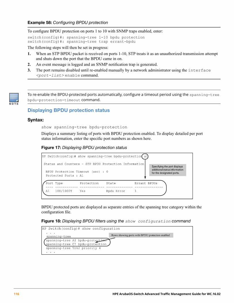
Example 58: Configuring BPDU protection
To configure BPDU protection on ports 1 to 10 with SNMP traps enabled, enter:
switch(config)#: spanning-tree 1-10 bpdu protectionswitch(config)#: spanning-tree trap errant-bpdu
The following steps will then be set in progress:
1. When an STP BPDU packet is received on ports 1-10, STP treats it as an unauthorized transmission attemptand shuts down the port that the BPDU came in on.
2. An event message is logged and an SNMP notification trap is generated.3. The port remains disabled until re-enabled manually by a network administrator using the interface
<port-list> enable command.
To re-enable the BPDU-protected ports automatically, configure a timeout period using the spanning-treebpdu-protection-timeout command.
Displaying BPDU protection status
Syntax:
show spanning-tree bpdu-protection
Displays a summary listing of ports with BPDU protection enabled. To display detailed per portstatus information, enter the specific port numbers as shown here.
Figure 17: Displaying BPDU protection status
BPDU protected ports are displayed as separate entries of the spanning tree category within theconfiguration file.
Figure 18: Displaying BPDU filters using the show configuration command
116 HPE ArubaOS-Switch Advanced Traffic Management Guide for WC.16.02

Configuring PVST
Enabling and disabling PVST protection on ports
Syntax:
[no] spanning-tree <port-list> pvst-protection
Enables or disables PVST protection on the ports specified. The command indicates which portsare not expected to receive any PVST BPDUs.
Default: Disabled on all ports.
Example 59: Enabling PVST protection
To enable the PVST protection feature on ports 4 through 8, enter:
switch(config)#: spanning-tree 4-8 pvst-protection
To disable the PVST protection feature on a port, for example, port 4, enter:
switch(config)#: no spanning-tree 4 pvst-protection
Enabling and disabling PVST filters on ports
Syntax:
[no] spanning-tree <port-list> pvst-filter
Enables or disables PVST filters on the ports specified. The command indicates which ports are notexpected to receive any PVST BPDUs.
Default: Disabled on all ports
Example 60: Enabling PVST filtering on a port
switch(config)#: spanning-tree 8 pvst-filter
Warning: The BPDU filter allows the port to go into a continuous forwarding modeand spanning-tree will not interfere,even if the port would cause a loop to form in the network topology.If you suddenly experience high traffic load, disable the port and reconfigure the BPDU filterwith the CLI command(s):
"no spanning-tree PORT_LIST bpdu-filter""no spanning-tree PORT_LIST pvst-filter"
Re-enabling a port manually
Syntax:
[no] spanning-tree bpdu-protection-timeout <timeout>
Configures the duration of time protected ports remain disabled. The default value of 0 sets aninfinite timeout, so ports that are disabled are not re-enabled automatically.
This is a GLOBAL command.
Range: 0 - 65535 seconds; Default: 0
You can also set the timeout in the MIB with this MIB object:hpSwitchStpBpduProtectionTimeout
Chapter 5 Multiple Instance Spanning Tree Operation 117
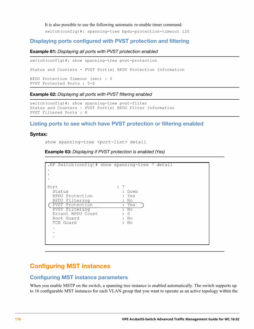
It is also possible to use the following automatic re-enable timer command:
switch(config)#: spanning-tree bpdu-protection-timeout 120
Displaying ports configured with PVST protection and filtering
Example 61: Displaying all ports with PVST protection enabled
switch(config)#: show spanning-tree pvst-protection
Status and Counters - PVST Port(s) BPDU Protection Information
BPDU Protection Timeout (sec) : 0PVST Protected Ports : 5-6
Example 62: Displaying all ports with PVST filtering enabled
switch(config)#: show spanning-tree pvst-filterStatus and Counters - PVST Port(s) BPDU Filter InformationPVST Filtered Ports : 8
Listing ports to see which have PVST protection or filtering enabled
Syntax:
show spanning-tree <port-list> detail
Example 63: Displaying if PVST protection is enabled (Yes)
Configuring MST instances
Configuring MST instance parametersWhen you enable MSTP on the switch, a spanning tree instance is enabled automatically. The switch supports upto 16 configurable MST instances for each VLAN group that you want to operate as an active topology within the
118 HPE ArubaOS-Switch Advanced Traffic Management Guide for WC.16.02

region to which the switch belongs. When creating an instance, you must include a minimum of one VID. You canadd more VIDs later if desired.
When the 2920 Switch is configured in a stack, the number of configurable MSTIs is limited to four. Ifstacking is enabled and a fifth MSTI is created, an error will occur.
However, when the 2920 Switch is configured as a standalone, a maximum of 16 MSTIs is supported.
Syntax:
[no] spanning-tree instance <1..4> vlan <vid> [<vid..vid>]
Configuring MSTP on the switch automatically configures the IST instance and places all staticallyand dynamically configured VLANs on the switch into the IST instance. This command creates anew MST instance (MSTI) and moves the VLANs you specify from the IST to the MSTI.
You must map at least one VLAN to an MSTI when you create it. You cannot map a VLAN ID tomore than one instance. You can create up to 16 MSTIs in a region.
The no form of the command removes one or more VLANs from the specified MSTI. If no VLANsare specified, the no form of the command deletes the specified MSTI.
When you remove a VLAN from an MSTI, the VLAN returns to the IST instance, where it canremain or be re-assigned to another MSTI configured in the region.
You can enter the spanning-tree instance vlan command before a static or dynamicVLAN is configured on the switch to preconfigure VLAN ID-to-MSTImappings. No errormessageis displayed. Later, each newly configured VLAN that has already been associated with anMSTIis automatically assigned to the MSTI.
This new default behavior differs from automatically including configured (static and dynamic)VLANs in the IST instance and requiring the manual assigning of individual static VLANs to anMSTI.
The valid VLAN IDs that you canmap to a specifiedMSTI are from1 to 4094. The VLAN ID-to-MSTImapping does not require a VLAN to be already configured on the switch. The MSTP VLANenhancement allows you to preconfigureMSTP topologies before the VLAN IDs associatedwitheach instance exist on a switch.
Setting the bridge priority for an instance
Syntax:
spanning-tree instance <1..4> priority <priority-multiplier>
Sets the switch (bridge) priority for the designated instance. This priority is compared with thepriorities of other switches in the same instance to determine the root switch. The lower the priorityvalue, the higher the priority. If there is only one switch in the instance, then that switch is the rootswitch for the instance. The IST regional root bridge provides the path to instances in other regionsthat share one or more of the same VLANs.
Chapter 5 Multiple Instance Spanning Tree Operation 119
The priority range for an MSTP switch is 0 - 61440. However, this command specifies the priorityas a multiplier (0 - 15) of 4096. When a priority multiplier value is set from 0 - 15, the actual priorityassigned to the switch for the specified MST instance is: (priority-multiplier) x 4096
For example, if you configure 5 as the priority-multiplier for MST Instance 1 on a given MSTPswitch, the Switch Priority setting is 20,480 for that instance in that switch.
If multiple switches in the same MST instance have the same priority setting, the switch withthe lowest MAC address becomes the root switch for that instance.
Configuring MST instance per-port parameters
Assigning a port cost for an MST instance
Syntax:
spanning-tree instance <ist | 1..4> <port-list> path-cost [auto |<1..200000000>]
Assigns an individual port cost for the IST or for the specified MST instance.
For a given port, the path cost setting can be different for different MST instances to which the portmay belong. The switch uses the path cost to determine which ports are the forwarding ports in theinstance; that is, which links to use for the active topology of the instance and which ports to block.
The settings are either auto or in a range from 1 to 200,000,000. With the auto setting, the switchcalculates the path cost from the link speed:10 Mbps 2000000
100 Mbps 200000
1 Gbps 20000
Default Auto
Setting the priority for a port in a specified MST instance
Syntax:
spanning-tree instance <1..4 port-list> priority<priority-multiplier>
Sets the priority for the specified ports in the specified MST instance.
For a given port, the priority setting can be different for different MST instances to which the portmay belong. The priority range for a port in a given MST instance is 0 - 255. However, this commandspecifies the priority as a multiplier (0 - 15) of 16. When you specify a priority multiplier of 0 - 15,the actual priority assigned to the switch is: (priority-multiplier) x 16
120 HPE ArubaOS-Switch Advanced Traffic Management Guide for WC.16.02

Example 64: Setting priority for a port in a specified MST instance
If you configure 2 as the priority multiplier on a given port in an MST instance, then the actual Priority setting is32x. After you specify the port priority multiplier in an instance, the switch displays the actual port priority and notthe multiplier in theshow spanning-tree instance <1..4> orshow spanning-tree <port-list>instance <1..4> displays.
You can view the actual multiplier setting for ports in the specified instance by executing show running andlooking for an entry in the following format:
spanning-tree instance < 1..4 port-list> priority <priority-multiplier>
For example, configuring port A2 with a priority multiplier of 3 in instance 1, results in this line in the showrunning output:
spanning-tree instance 1 A2 priority 3
Setting the priority for specified ports for the IST
Syntax:
spanning-tree <port-list> priority <priority-multiplier>
Sets the priority for the specified ports for the IST (Instance 0) of the region in which the switchresides.
The priority component of the port's Port Identifier is set. The Port Identifier is a unique identifierthat helps distinguish this switch's ports from all others. It consists of the priority value with theport number extension—PRIORITY:PORT_NUMBER. A port with a lower value of Port Identifieris more likely to be included in the active topology.
This priority is compared with the priorities of other ports in the IST to determine which port is theroot port for the IST instance. The lower the priority value, the higher the priority. The IST rootport (or trunk) in a region provides the path to connected regions for the traffic in VLANs assignedto the region's IST instance.
The priority range for a port in a given MST instance is 0 - 240. However, this command specifiesthe priority as a multiplier (0 - 15) of 16. When you specify a priority multiplier of 0 - 15, the actualpriority assigned to the switch is: (priority-multiplier) x 16
Example 65: Setting priority for specified ports for an IST
Configuring 5 as the priority multiplier on a given port in the IST instance for a region creates anactual priority setting of 80. After specifying the port priority multiplier for the IST instance, theswitch displays the actual port priority, not the multiplier, in the show spanning-treeinstance ist orshow spanning-tree <port-list> instance ist displays. Youcan view the actual multiplier setting for ports in the IST instance by executing show runningand looking for an entry in this format:
spanning-tree <port-list> priority <priority-multiplier>
So configuring port A2 with a priority multiplier of 2 in the IST instance, results in this line in theshow running output:
spanning-tree A2 priority 2
Enabling or disabling spanning tree operationThis command enables or disables spanning tree operation for any spanning tree protocol enabled on the switch.Before using to enable spanning tree, ensure that the right version is active on the switch.
Chapter 5 Multiple Instance Spanning Tree Operation 121

Syntax:
[no] spanning-tree
Enables or disables spanning tree. Enabling spanning tree with MSTP configured, implements MSTPfor all physical ports on the switch according to the VLAN groupings for the IST instance and anyother configured instances.
Disabling MSTP removes protection against redundant loops that can significantly slow or halt anetwork.
This command simply turns spanning tree on or off. It does not change the existing spanning treeconfiguration.
The convergence time for implementing MSTP changes can be disruptive to your network. To minimize suchdisruption, consider using the spanning-tree pending command (see “Enabling an entire MST region atonce or exchanging one region configuration for another” (page 122)).
Enabling an entire MST region at once or exchanging one region configuration for another
This operation exchanges the currently active MSTP configuration with the currently pending MSTP configuration,making it possible to implement a new MSTP configuration with minimal network disruption or to exchange MSTPconfigurations for testing or troubleshooting purposes.
When configuring or reconfiguring MSTP, the switch recalculates the corresponding network paths. This can havea ripple effect throughout your network as adjacent MSTP switches recalculate network paths to support theconfiguration changes invoked in a single switch. Although MSTP employs rapid spanning tree operation, theconvergence time for implementing MSTP changes can be disruptive to your network. However, by using thespanning-tree pending feature, you can set up an MSTP on the switch and then invoke all instances of thenew configuration at the same time, instead of one at a time.
Syntax:
[no] spanning-tree pending [ apply | <config-name> |<config-revision> | instance | reset ]
Exchanges the currently active MSTP configuration with the current pending MSTP configuration.Options are as follows:
apply Exchanges the currently active MSTP configuration withthe pending MSTP configuration.
<config-name> Specifies the pending MST region name. Must be the samefor all MSTP switches in the region. (Default: The switch'sMAC address.)
<config-revision> Specifies the pending MST region configuration revisionnumber. Must be the same for all MSTP switches in theregion. (Default: 0).
instance <1..4> vlan [vid| <vid-range> ]
Creates the pending instance and assigns one or moreVLANs to the instance.
reset Copies the switch's currently active MSTP configurationto the pending configuration. This is useful when you wantto experiment with the current MSTP configuration whilemaintaining an unchanged version.
122 HPE ArubaOS-Switch Advanced Traffic Management Guide for WC.16.02
Creating a pending MSTP configuration
To create a pending MSTP configuration and exchange it with the active MSTP configuration:
1. Configure the VLANs to include in any instances in the new region. When you execute the pending command,all VLANs configured on the switch will be assigned to a single pending IST instance unless assigned to other,pending MST instances. The pending command creates the region's IST instance automatically.
2. Configure MSTP as the spanning tree protocol, then execute write mem and reboot. The pending option isavailable only with MSTP enabled.
3. Configure the pending region <config-name> to assign to the switch.4. Configure the pending <config-revision> number for the region name.5. If you want an MST instance other than the IST instance, configure the instance number and assign the
appropriate VLANs (VIDs) using the pending instance <1..4> vlan [ vid | <vid-range>]
6. Repeat step 5 for each additional MST instance necessary.7. To review your pending configuration, use the show spanning-tree pending command.8. To exchange the currently active MSTP configuration with the pending MSTP configuration, use the
spanning-tree pending apply command.
MSTP topologies
Preconfiguring an MSTP regional topologyThe MSTP VLAN configuration enhancement allows you to preconfigure an MSTP regional topology and ensurethat the same VLAN ID-to-MSTI assignments exist on each MSTP switch in the region.
When this software version is installed, the prior VLAN ID-to-MSTI mappings do not change. However, thisenhancement is not backward-compatible. If you install a software version earlier than this version and youhave configured MSTI entries instances mapped to VLANs, they will be removed from the configuration filewhen booting to the prior version of software. Do one of the following to install or reload a prior version ofthe software:1. Remove all MSTP mappings from the configuration file, then reconfigure the instance mapping after
running the desired software version.2. Save the current configuration file before updating the software to a new version. If you later reload this
older version of the software, use this configuration file when you reload the older version. See “Savingthe current configuration before a software upgrade” (page 126).
The default behavior of the spanning-tree instance vlan command changes so that, before a static VLANis configured or a dynamic VLAN is learned on the switch, you can preconfigure its VLAN ID-to-MSTI mapping.Later, when the VLAN is created, it is automatically assigned to the MSTI to which it was previously mapped.
By supporting preconfigured VLAN ID-to-MSTI topologies, the VLAN configuration enhancement provides thefollowing benefits:
• Scalability: In a network design in which you plan to use a large number of VLANs, you can preconfigureidentical VLAN ID-to-MSTI mappings on all switches in a single, campus-wide MST region, regardless of the
Chapter 5 Multiple Instance Spanning Tree Operation 123

specific VLANs that you later configure on each switch. After the initial VLAN ID-to-MSTI mapping, you candecide on the exact VLANs that you need on each switch.
All switches in a region must be configured with the same VLAN ID-to-MSTI mappings and the same MSTPconfiguration identifiers (region name and revision number).
• Flexibility: By preconfiguring identical VLAN ID-to-MSTI mappings on all switches in an MST region, youcan combine switches that support different maximum numbers of VLANs.
• Network stability: You can reduce the interruptions in network connectivity caused by the regeneration ofspanning trees in the entire network each time a configuration change in VLAN-to-MSTI mapping is detectedon a switch. The negative impact on network performance is reduced if all newly created VLANs are pre-mappedto the correct MST instances. Later, VLAN creation and deletion are ignored by MSTP and no interruption inspanning tree traffic occurs.
• Usability: Dynamically learned GVRP VLANs can be mapped to MSTIs and support MSTP load balancing.
Preconfiguring VLANs in an MST instance
When configuring an MSTP regional topology, multiple spanning tree instances are created. Each MST instanceprovides a fully connected active topology for a particular set of VLANs.
Each switch in an MSTP region is configured with the following set of common parameters:
• Region name (spanning-tree config-name)
• Region revision number (spanning-tree config-revision)
• Identical VLAN ID-to-MSTI mapping (spanning-tree instance vlan)
Syntax:
[no] spanning-tree instance <1..4> vlan <vid> [<vid..vid>]
Configuring MSTP on the switch automatically configures the IST instance and places all staticallyand dynamically configured VLANs on the switch into the IST instance. This command creates anew MST instance (MSTI) and moves the VLANs specified from the IST to the MSTI.
You must map at least one VLAN to an MSTI when you create it. You cannot map a VLAN ID tomore than one instance. You can create up to 16 MSTIs in a region.
The no form of the command removes one or more VLANs from the specified MSTI. If no VLANsare specified, the no form of the command deletes the specified MSTI.
When removing a VLAN from an MSTI, the VLAN returns to the IST instance, where it remainsor is reassigned to another MSTI configured in the region.
The valid VLAN IDs tomap to a specifiedMSTI are from1 to 4094. The VLAN ID-to-MSTImappingdoes not require a VLAN to be already configured on the switch. TheMSTP VLAN enhancementallows preconfiguringMSTP topologies before the VLAN IDs associatedwith each instance existon a switch.
When using preconfigured VLAN ID-to-MSTI topologies, ensure that MSTP switches remain inthe same region by mapping all VLAN IDs used in the region to the same MSTIs on each regionalswitch.
Each MST instance supports a different set of VLANs. A VLAN that is mapped to an MST instancecannot be a member of another MST instance.
124 HPE ArubaOS-Switch Advanced Traffic Management Guide for WC.16.02

Configuring MSTP instances with the VLAN range option (Example)
Example 66: Mapping VLANs to MSTP Instance
If VLANs 1, 5 and 7 are currently present and you enter the following command, all the VLANs from 1 through 10are included, even those VLANs that are not present.
switch(config)#: spanning-tree instance 1 vlan 1-10
On switches other than those covered by this guide, only the VLANs that are present will be included, that is, onlyVLANs 1, 5 and 7. The switch will map these VLANs to MSTP Instance 1, which results in a Configuration Digestthat is not the same as the Configuration Digest for the switches running this enhancement. (See Example 67 “MappingVLANs with the range option where all VLANs are included” and Example 68 “Mapping VLANs on other switches”)
Example 67 “Mapping VLANs with the range option where all VLANs are included” shows an example of an MSTPinstance configured with the VLAN range option. All the VLANs are included in the instance whether they exist ornot. Example 68 “Mapping VLANs on other switches” shows an example of an MSTP instance configured onanother switch. Only VLANs 1, 5 and 7 are included in the instance.
Example 67: Mapping VLANs with the range option where all VLANs are included
The Configuration Digest value shown in Example 68 “Mapping VLANs on other switches” is not the same as inExample 67 “Mapping VLANs with the range option where all VLANs are included”, indicating that these switchesdo not operate in the same instance.
The Common Spanning Tree (CST) will still have the correct root associations.
Example 68: Mapping VLANs on other switches
See “Operating notes for the VLAN configuration enhancement” (page 159).
Chapter 5 Multiple Instance Spanning Tree Operation 125

Saving the current configuration before a software upgrade
Before updating to a new version of software, follow these steps:
1. Enter the show config files command to display your current configuration files:
switch(config)#: show config files
Configuration files:
id | act pri sec | name---+-------------+--------------------1 | * * * | config12 | | config23 | |
2. To save a configuration file for software version K.12.43, enter this command:
switch(config)#: copy config config1 config configK1243.cfg
Choose any name for the saved configuration file that you prefer.
3. Display the configuration files as shown in the following example. Note the newly created configuration filelisted.
switch(config)#: show config files
Configuration files:
id | act pri sec | name---+-------------+----------------------1 | * * * | config12 | | config23 | | configK1243.cfg
4. Update the switch to the desired version, for example, K.12.51. Enter the show flash command to see theresults. The switch is now running the software version K.12.51.
switch(config)#: show flash
Image Size(Bytes) Date Version Build #:----- ---------- -------- ------- -------Primary Image : 6771179 04/17/08 K.12.51 304Secondary Image : 7408949 11/06/08 K.12.43 123Boot Rom Version: K.12.12Default Boot : Primary
5. To run the prior software version (K.12.43 in this example), enter this command:
switch(config)#: boot system flash secondary config configK1243.cfg
After rebooting, the switch is running software version K.12.43 and is using the configuration file that yousaved for this software version, configK1243.cfg.
You can also save the K.12.43 configuration file on a TFTP server. To reload the K.12.43 version of the softwareagain, reload the configuration file before doing the reload.
Displaying MSTP statistics
SNMP MIB Support for MSTP is a superset of the STP/802.1D and RSTP/802.1w protocols and uses the MIBobjects defined for these two protocols.
126 HPE ArubaOS-Switch Advanced Traffic Management Guide for WC.16.02

Displaying global MSTP status
The following commands display the MSTP statistics for the connections between MST regions in a network.
Syntax:
show spanning-tree
Displays the switch's global and regional spanning tree status, plus the per-port spanning treeoperation at the regional level. Values for the following parameters appear only for ports connectedto active devices: Designated Bridge, Hello Time, PtP and Edge.
Syntax:
show spanning-tree <port-list>
Displays the spanning tree status for the designated ports. You can list data for a series of ports andport trunks by specifying the first and last port or trunk of any consecutive series of ports and trunks.For example, to display data for port A20-A24 and trk1, you would use this command: showspanning-tree a20-a42,trk1
Chapter 5 Multiple Instance Spanning Tree Operation 127
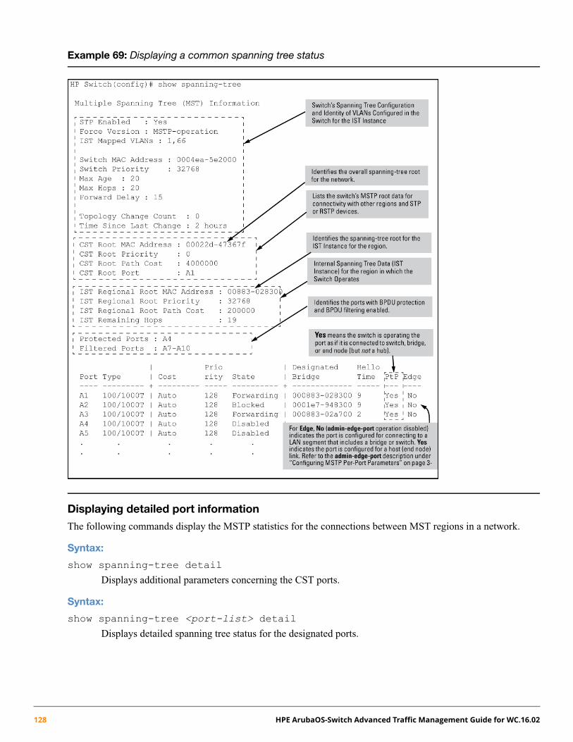
Example 69: Displaying a common spanning tree status
Displaying detailed port information
The following commands display the MSTP statistics for the connections between MST regions in a network.
Syntax:
show spanning-tree detail
Displays additional parameters concerning the CST ports.
Syntax:
show spanning-tree <port-list> detail
Displays detailed spanning tree status for the designated ports.
128 HPE ArubaOS-Switch Advanced Traffic Management Guide for WC.16.02
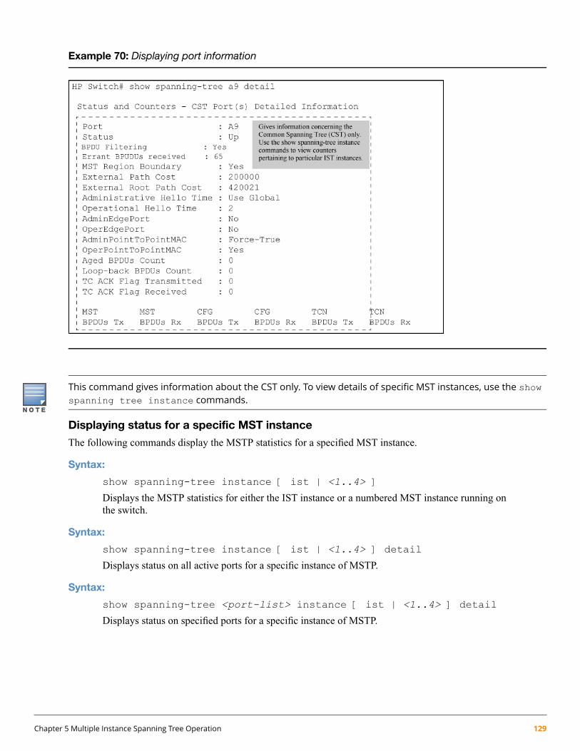
Example 70: Displaying port information
This command gives information about the CST only. To view details of specific MST instances, use the showspanning tree instance commands.
Displaying status for a specific MST instance
The following commands display the MSTP statistics for a specified MST instance.
Syntax:
show spanning-tree instance [ ist | <1..4> ]
Displays the MSTP statistics for either the IST instance or a numbered MST instance running onthe switch.
Syntax:
show spanning-tree instance [ ist | <1..4> ] detail
Displays status on all active ports for a specific instance of MSTP.
Syntax:
show spanning-tree <port-list> instance [ ist | <1..4> ] detail
Displays status on specified ports for a specific instance of MSTP.
Chapter 5 Multiple Instance Spanning Tree Operation 129

Example 71: Displaying status for a specific instance of an MSTP
This shows how to display detailed status for all active ports for a specific instance of MSTP.
switch(config)#: show spanning-tree instance 11MST Instance InformationInstance ID : 11Mapped VLANs : 111,300Switch Priority : 32768
Topology Change Count : 2Time Since Last Change : 4 mins
Regional Root MAC Address : 1cc1de-cfbc80Regional Root Priority : 32768Regional Root Path Cost : 400000Regional Root Port : This switch is rootRemaining Hops : 20
DesignatedPort Type Cost Priority Role State Bridge----- --------- --------- -------- ---------- ---------- -------------1 10/100TX 200000 128 Root Forwarding 1cc1de-cfbc802 10/100TX 200000 128 Designated Forwarding 1cc1de-02a7003 10/100TX Auto 112 Designated Forwarding 1cc1de-02a7004 10/100TX Auto 128 Disabled Disabled. . . . . .
Displaying the MSTP configuration
Displaying the global MSTP configuration
This command displays the switch's basic and MST region spanning tree configuration, including basic portconnectivity settings.
Syntax:
show spanning-tree config
The upper part of this output shows the switch's global spanning tree configuration that applies tothe MST region. The port listing shows the spanning tree port parameter settings for the spanningtree region operation configured by the spanning-tree <port-list> command. Forinformation on these parameters, see “Configuring MSTP per-port parameters” (page 111).
Syntax:
show spanning-tree <port-list> config
This command shows the same data as the above command, but lists the spanning tree port parametersettings for only the specified port or trunk. You can list data for a series of ports and port trunksby specifying the first and last port or trunk of any consecutive series of ports and trunks. Forexample, to display data for port A20-A24 andtrk1, use the command: show spanning-treea20-a24,trk1 config
130 HPE ArubaOS-Switch Advanced Traffic Management Guide for WC.16.02
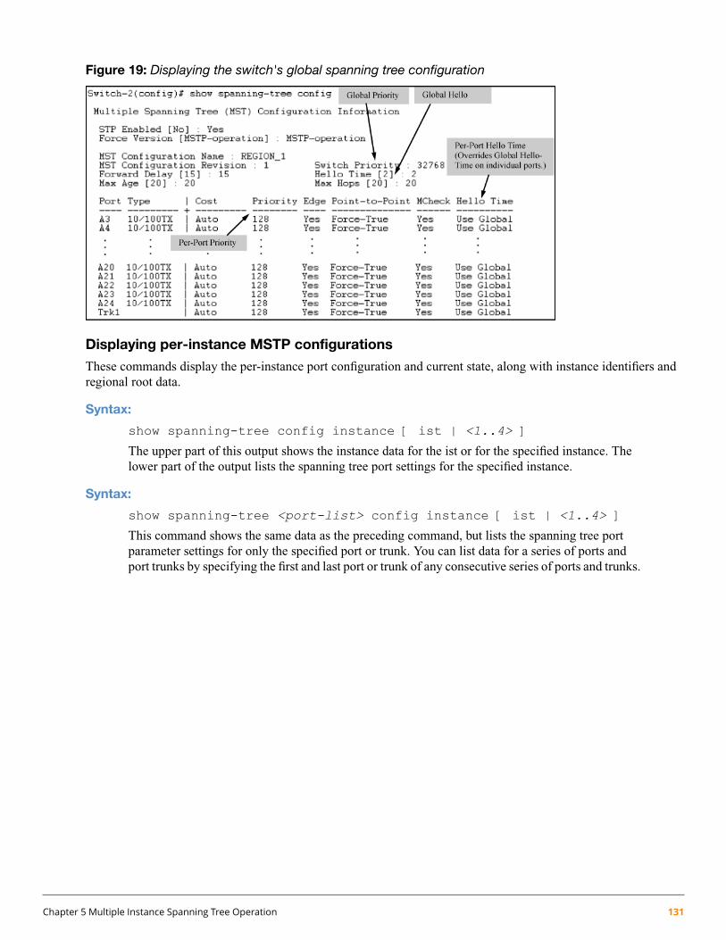
Figure 19: Displaying the switch's global spanning tree configuration
Displaying per-instance MSTP configurations
These commands display the per-instance port configuration and current state, along with instance identifiers andregional root data.
Syntax:
show spanning-tree config instance [ ist | <1..4> ]
The upper part of this output shows the instance data for the ist or for the specified instance. Thelower part of the output lists the spanning tree port settings for the specified instance.
Syntax:
show spanning-tree <port-list> config instance [ ist | <1..4> ]
This command shows the same data as the preceding command, but lists the spanning tree portparameter settings for only the specified port or trunk. You can list data for a series of ports andport trunks by specifying the first and last port or trunk of any consecutive series of ports and trunks.
Chapter 5 Multiple Instance Spanning Tree Operation 131

Example 72: Displaying port data
To display data for ports A20-A24 and trk1, you would use the command:
switch(config)#: show spanning-tree a20-a24,trk1 config instance 1
Displaying the region-level configuration
This command is useful for quickly verifying the allocation of VLANs in the switch's MSTP configuration and forviewing the configured region identifiers.
Syntax:
show spanning-tree mst-config
The switch computes the MSTP Configuration Digest from the VID to MSTI configurationmappings on the switch itself. As required by the 802.1s standard, all MSTP switches within thesame region must have the same VID to MSTI assignments and any given VID can be assignedto either the IST or one of the MSTIs within the region. Thus, the MSTP Configuration Digestmust be identical for all MSTP switches intended to belong to the same region.When comparingtwo MSTP switches, if their Digest identifiers do not match, they cannot be members of thesame region. (See Example 73 (page 133).)
132 HPE ArubaOS-Switch Advanced Traffic Management Guide for WC.16.02

Example 73: Displaying a region-level configuration
switch(config)#: show spanning-tree net-config
MST Configuration Identifier Information
MST Configuration Name : REGION_1MST Configuration Revision : 1MST Configuration Digest : 0xDAD6A13EC5141980B7EBDA71D8991E7C
IST Mapped VLANs : 1,66
Instance ID Mapped VLANs-------- ---------------1 11,222 33,44,55
Displaying the pending MSTP configuration
This command displays the MSTP configuration the switch will implement if you execute the spanning treepending apply command. See “Enabling an entire MST region at once or exchanging one region configurationfor another” (page 122).
Syntax:
show spanning-tree pending [ instance | mst-config ]instance [ <1..4> | ist ] Lists region, instance ID, and VLAN information for the
specified, pending instance.
mst-config Lists region, IST instance VLANs, numbered instancesand assigned VLAN information for the pending MSTPconfiguration.
Chapter 5 Multiple Instance Spanning Tree Operation 133
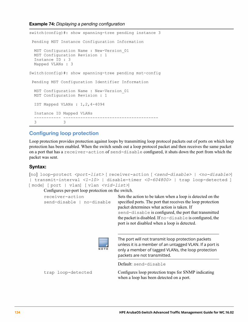
Example 74: Displaying a pending configuration
switch(config)#: show spanning-tree pending instance 3
Pending MST Instance Configuration Information
MST Configuration Name : New-Version_01MST Configuration Revision : 1Instance ID : 3Mapped VLANs : 3
Switch(config)#: show spanning-tree pending mst-config
Pending MST Configuration Identifier Information
MST Configuration Name : New-Version_01MST Configuration Revision : 1
IST Mapped VLANs : 1,2,4-4094
Instance ID Mapped VLANs----------- ---------------------------------------3 3
Configuring loop protectionLoop protection provides protection against loops by transmitting loop protocol packets out of ports on which loopprotection has been enabled. When the switch sends out a loop protocol packet and then receives the same packeton a port that has a receiver-action of send-disable configured, it shuts down the port from which thepacket was sent.
Syntax:
[no] loop-protect <port-list> [receiver-action [<send-disable> | <no-disable>]| transmit-interval <1-10> | disable-timer <0-604800> | trap loop-detected ][mode] [port | vlan] [vlan <vid-list>]
Configures per-port loop protection on the switch.receiver-actionsend-disable | no-disable
Sets the action to be taken when a loop is detected on thespecified ports. The port that receives the loop protectionpacket determines what action is taken. Ifsend-disable is configured, the port that transmittedthe packet is disabled. If no-disable is configured, theport is not disabled when a loop is detected.
The port will not transmit loop protection packetsunless it is a member of an untagged VLAN. If a port isonly a member of tagged VLANs, the loop protectionpackets are not transmitted.
Default: send-disable
trap loop-detected Configures loop protection traps for SNMP indicatingwhen a loop has been detected on a port.
134 HPE ArubaOS-Switch Advanced Traffic Management Guide for WC.16.02

disable-timer <0-604800> Configures how long (in seconds) a port is disabled whena loop has been detected. A value of zero disables the autore-enable function.
Default: Timer is disabled
transmit-interval <1-10> Configures the time in seconds between the transmissionof loop protection packets.
Default: 5 seconds
mode port | vlan Configures loop protection in port or VLAN mode.
vlan <vlan-id-list> Configures the VLANs on which loop-protect is enabled.Maximum number of loop-protected VLANS is 32.
Enabling loop protection in port mode
Follow these steps.
1. Configure port mode with this command:
switch(config)#: loop-protect mode port
2. Enter the loop-protect command and specify the ports on which loop protection should be enabled. Forexample:
switch(config)#: loop-protect 1-2
3. Optionally specify receiver-action of send-disable to shut down the port in the event of a loop.For example:
switch(config)#: loop-protect 1-2 receiver-action send-disable
Enabling loop protection in VLAN mode
VLANs can be configured for loop protection only when operating in VLAN mode. When loop-protect isenabled for a VLAN and a loop-protect enabled interface is a member of that VLAN, loop protect packets aresent on that VLAN to detect loops.
To enable loop protection in VLAN mode:
1. Configure VLAN mode with the command:
switch(config)#: loop-protect mode vlan
2. Enter the loop-protect command and specify the VLANs on which loop protection should be enabled.For example:
switch(config)#: loop-protect vlan 20,30
Changing modes for loop protection
When changing from VLAN mode to port mode, the following prompt appears. The VLANs are then no longerconfigured for loop protection.
Chapter 5 Multiple Instance Spanning Tree Operation 135

Example 75: Changing modes for loop protection
switch(config)#: loop-protect mode portAny Loop Protect enabled VLAN will be deleted. Do you want to continue [Y/N]?N
Displaying loop protection status
Syntax:
Displays the loop protection status for VLANs. If no ports are specified, the information is displayedonly for ports with loop protection enabled.
Example 76: Displaying loop protection information for port mode
switch(config)#: show loop-protect 1-2
Status and Counters - Loop Protection Information
Transmit Interval (sec) : 5Port Disable Timer (sec) : 5Loop Detected Trap : EnabledLoop Protect Mode : portLoop Protect Enabled VLANs :
Loop Loop Detected Loop Time Since Rx PortPort Protect Detected on VLAN Count Last Loop Action Status---- ------- -------- --------- -------- ----------- ---------- ---------1 Yes Yes 1 5s send-disable Down2 Yes No 0 send-disable Up
Displaying loop protection status in VLAN mode
Syntax:
show loop-protect <port-list>Displays the loop protection status for VLANs. If no ports are specified, the information is displayedonly for the ports that have loop protection enabled.
136 HPE ArubaOS-Switch Advanced Traffic Management Guide for WC.16.02
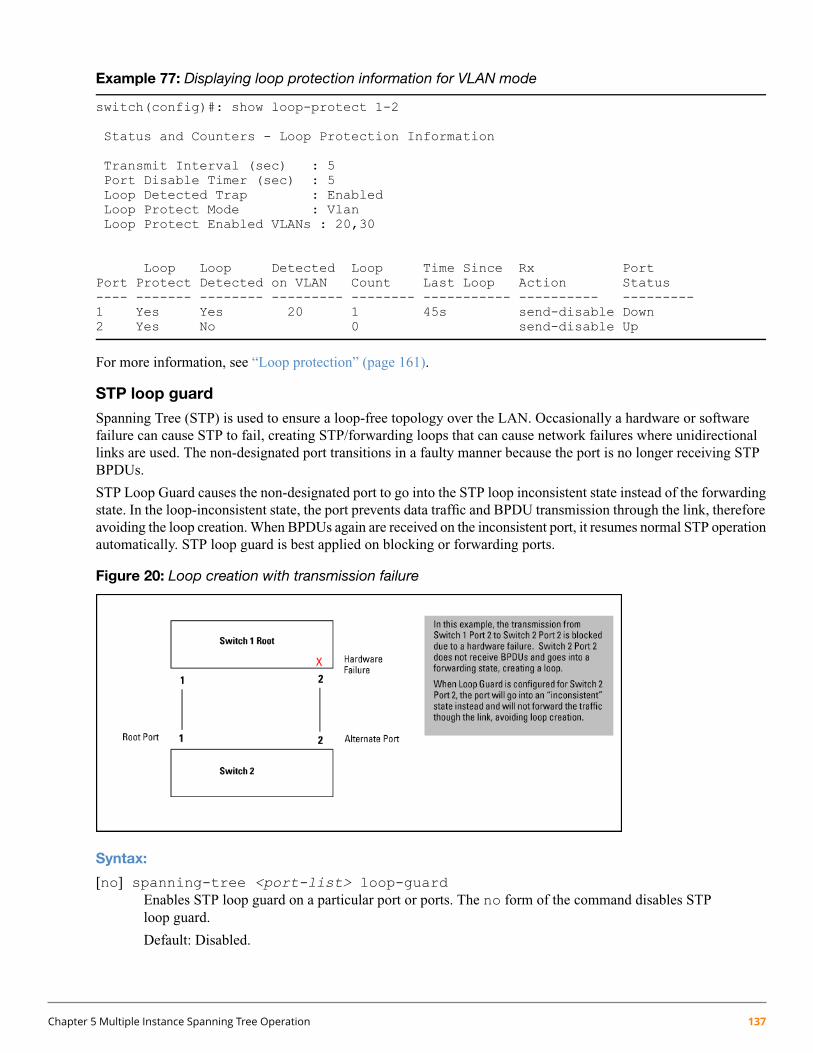
Example 77: Displaying loop protection information for VLAN mode
switch(config)#: show loop-protect 1-2
Status and Counters - Loop Protection Information
Transmit Interval (sec) : 5Port Disable Timer (sec) : 5Loop Detected Trap : EnabledLoop Protect Mode : VlanLoop Protect Enabled VLANs : 20,30
Loop Loop Detected Loop Time Since Rx PortPort Protect Detected on VLAN Count Last Loop Action Status---- ------- -------- --------- -------- ----------- ---------- ---------1 Yes Yes 20 1 45s send-disable Down2 Yes No 0 send-disable Up
For more information, see “Loop protection” (page 161).
STP loop guard
Spanning Tree (STP) is used to ensure a loop-free topology over the LAN. Occasionally a hardware or softwarefailure can cause STP to fail, creating STP/forwarding loops that can cause network failures where unidirectionallinks are used. The non-designated port transitions in a faulty manner because the port is no longer receiving STPBPDUs.
STP Loop Guard causes the non-designated port to go into the STP loop inconsistent state instead of the forwardingstate. In the loop-inconsistent state, the port prevents data traffic and BPDU transmission through the link, thereforeavoiding the loop creation. When BPDUs again are received on the inconsistent port, it resumes normal STP operationautomatically. STP loop guard is best applied on blocking or forwarding ports.
Figure 20: Loop creation with transmission failure
Syntax:
[no] spanning-tree <port-list> loop-guardEnables STP loop guard on a particular port or ports. The no form of the command disables STPloop guard.
Default: Disabled.
Chapter 5 Multiple Instance Spanning Tree Operation 137
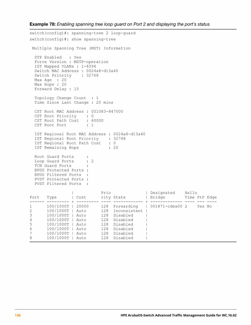
Example 78: Enabling spanning tree loop guard on Port 2 and displaying the port's status
switch(config)#: spanning-tree 2 loop-guard
switch(config)#: show spanning-tree
Multiple Spanning Tree (MST) Information
STP Enabled : YesForce Version : MSTP-operationIST Mapped VLANs : 1-4094Switch MAC Address : 0024a8-d13a40Switch Priority : 32768Max Age : 20Max Hops : 20Forward Delay : 15
Topology Change Count : 1Time Since Last Change : 20 mins
CST Root MAC Address : 001083-847000CST Root Priority : 0CST Root Path Cost : 60000CST Root Port : 1
IST Regional Root MAC Address : 0024a8-d13a40IST Regional Root Priority : 32768IST Regional Root Path Cost : 0IST Remaining Hops : 20
Root Guard Ports :Loop Guard Ports : 2TCN Guard Ports :BPDU Protected Ports :BPDU Filtered Ports :PVST Protected Ports :PVST Filtered Ports :
| Prio | Designated HelloPort Type | Cost rity State | Bridge Time PtP Edge------ --------- + --------- ---- ------------ + ------------- ---- --- ----1 100/1000T | 20000 128 Forwarding | 001871-cdea00 2 Yes No2 100/1000T | Auto 128 Inconsistent |3 100/1000T | Auto 128 Disabled |4 100/1000T | Auto 128 Disabled |5 100/1000T | Auto 128 Disabled |6 100/1000T | Auto 128 Disabled |7 100/1000T | Auto 128 Disabled |8 100/1000T | Auto 128 Disabled |
138 HPE ArubaOS-Switch Advanced Traffic Management Guide for WC.16.02
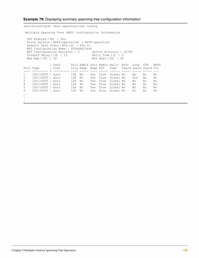
Example 79: Displaying summary spanning tree configuration information
switch(config)#: show spanning-tree config
Multiple Spanning Tree (MST) Configuration Information
STP Enabled [No] : YesForce Version [MSTP-operation] : MSTP-operationDefault Path Costs [802.1t] : 802.1tMST Configuration Name : 0024a8d13a40MST Configuration Revision : 0 Switch Priority : 32768Forward Delay [15] : 15 Hello Time [2] : 2Max Age [20] : 20 Max Hops [20] : 20
| Path Prio Admin Auto Admin Hello Root Loop TCN BPDUPort Type | Cost rity Edge Edge PtP Time Guard Guard Guard Flt---- --------- + --------- ---- ----- ---- ----- ------ ----- ----- ----- ---1 100/1000T | Auto 128 No Yes True Global No No No No2 100/1000T | Auto 128 No Yes True Global No Yes No No3 100/1000T | Auto 128 No Yes True Global No No No No4 100/1000T | Auto 128 No Yes True Global No No No No5 100/1000T | Auto 128 No Yes True Global No No No No6 100/1000T | Auto 128 No Yes True Global No No No No...
Chapter 5 Multiple Instance Spanning Tree Operation 139
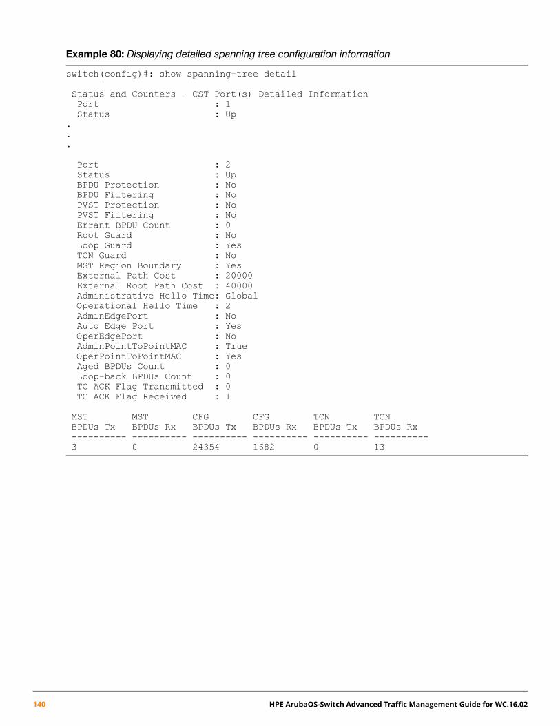
Example 80: Displaying detailed spanning tree configuration information
switch(config)#: show spanning-tree detail
Status and Counters - CST Port(s) Detailed InformationPort : 1Status : Up
.
.
.
Port : 2Status : UpBPDU Protection : NoBPDU Filtering : NoPVST Protection : NoPVST Filtering : NoErrant BPDU Count : 0Root Guard : NoLoop Guard : YesTCN Guard : NoMST Region Boundary : YesExternal Path Cost : 20000External Root Path Cost : 40000Administrative Hello Time: GlobalOperational Hello Time : 2AdminEdgePort : NoAuto Edge Port : YesOperEdgePort : NoAdminPointToPointMAC : TrueOperPointToPointMAC : YesAged BPDUs Count : 0Loop-back BPDUs Count : 0TC ACK Flag Transmitted : 0TC ACK Flag Received : 1
MST MST CFG CFG TCN TCNBPDUs Tx BPDUs Rx BPDUs Tx BPDUs Rx BPDUs Tx BPDUs Rx---------- ---------- ---------- ---------- ---------- ----------3 0 24354 1682 0 13
140 HPE ArubaOS-Switch Advanced Traffic Management Guide for WC.16.02

Example 81: Displaying spanning tree configuration information for a single port
switch(config)#: show spanning-tree 2
Multiple Spanning Tree (MST) Information
STP Enabled : YesForce Version : MSTP-operationIST Mapped VLANs : 1-4094Switch MAC Address : 0024a8-d13a40Switch Priority : 32768Max Age : 20Max Hops : 20Forward Delay : 15
Topology Change Count : 1Time Since Last Change : 58 mins
CST Root MAC Address : 001083-847000CST Root Priority : 0CST Root Path Cost : 60000CST Root Port : 1
IST Regional Root MAC Address : 0024a8-d13a40IST Regional Root Priority : 32768IST Regional Root Path Cost : 0IST Remaining Hops : 20
Root Guard Ports :Loop Guard Ports : 2TCN Guard Ports :BPDU Protected Ports :BPDU Filtered Ports :PVST Protected Ports :PVST Filtered Ports :
| Prio | Designated HelloPort Type | Cost rity State | Bridge Time PtP Edge------ --------- + --------- ---- ------------ + ------------- ---- --- ----2 100/1000T | Auto 128 Inconsistent |
Troubleshooting an MSTP configurationThis section describes the show spanning-tree commands to use to monitor, troubleshoot, and debug theoperation of a multiple-instance spanning tree configuration in a network.
The show spanning-tree commands described in this section allow for focusing on increasingly specificlevels of operation. For example, you can display debug information for:
• All MST instances
• All ports used in one MST instance
• A specific port or several ports used in one MST instance
Also, you can display the change history for the root (bridge) switch used as the single forwarding path for:
• All MST regions, STP bridges, and RSTP bridges in an STP network
• All VLANs on MSTP switches in a region
• All VLANs on MSTP switches in an mst instance
Chapter 5 Multiple Instance Spanning Tree Operation 141

Displaying the change history of root bridges
The show spanning-tree root-history command lets you display change history information (up to 10history entries) for a specified root bridge in any of the following MSTP topologies:
• Common Spanning Tree (cst):
Provides connectivity in a bridged network between MST regions, STP LANs, and RSTP LANs.
• Internal Spanning Tree (ist):
Provides connectivity within an MST region for VLANs associated with the default Common and InternalSpanning Tree (CIST) instance in your network (VLANs that have not been mapped to an MST instance).
• MST Instance (mst):
Connects all static and dynamic VLANs assigned to a multiple spanning tree instance.
Syntax:
show spanning tree root-history [ <cst | ist | mst ] <instance-id> >
Displays the change history for the root bridge in the specified MSTP topology.cst Displays the change history for the root bridge of a spanning tree
network, including MST regions and STP and RSTP bridges.
ist Displays the change history for the root bridge in the IST instance ofan MST region.
mst <instance-id> Displays the change history for the root bridge in an MST instance,where <instance-id> is an ID number from 1 to 16.
Use the show spanning-tree root-history command to view the number and dates of changes in theassignment of a root bridge. Possible intrusion into your MST network may occur if an unauthorized external devicegains access to a spanning tree by posing as the root device in a topology. To prevent an MST port connected to thedevice from being selected as the root port in a topology, use the spanning-tree root-guard command.
142 HPE ArubaOS-Switch Advanced Traffic Management Guide for WC.16.02

Example 82: Sample output of the show spanning-tree root-history command for differentMSTP topologies
The following examples show sample output of the show spanning-tree root-history command fordifferent MSTP topologies. In each example, the root bridge ID is displayed in the format: <priority>:<mac-address>
Where:
• <priority> is the MSTP switch priority calculated for one of the following:
• The IST (regional) root switch using the spanning-tree priority command
• An MSTI root switch using the spanning-tree instance priority command
• <mac-address> is the MAC address of the root (bridge) switch.
Example 83: Displaying show spanning-tree root-history CST output
Example 84: Displaying show spanning-tree root-history IST output
Chapter 5 Multiple Instance Spanning Tree Operation 143

Example 85: Displaying show spanning-tree root-history MSTI output
Displaying debug counters for all MST instances
The show spanning-tree debug-counters command allows you to display the aggregate values of allMSTP debug counters that are maintained on a switch. These aggregate values are a summary of the informationcollected from all ports and from all spanning tree instances that forward traffic on switch ports.
Use the displayed diagnostic information to globally monitor MSTP operation on a per-switch basis.
Syntax:
show spanning-tree debug-counters
Displays debug counters for MSTP activity on all ports configured for VLANs used in spanningtree instances.
144 HPE ArubaOS-Switch Advanced Traffic Management Guide for WC.16.02
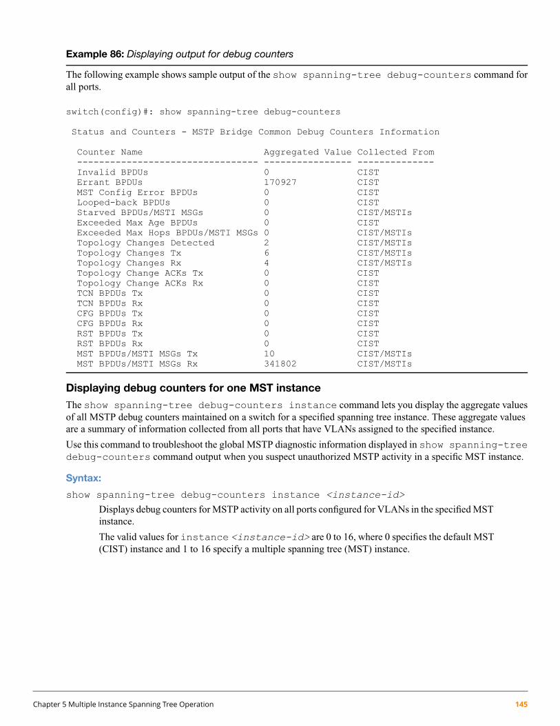
Example 86: Displaying output for debug counters
The following example shows sample output of the show spanning-tree debug-counters command forall ports.
switch(config)#: show spanning-tree debug-counters
Status and Counters - MSTP Bridge Common Debug Counters Information
Counter Name Aggregated Value Collected From--------------------------------- ---------------- --------------Invalid BPDUs 0 CISTErrant BPDUs 170927 CISTMST Config Error BPDUs 0 CISTLooped-back BPDUs 0 CISTStarved BPDUs/MSTI MSGs 0 CIST/MSTIsExceeded Max Age BPDUs 0 CISTExceeded Max Hops BPDUs/MSTI MSGs 0 CIST/MSTIsTopology Changes Detected 2 CIST/MSTIsTopology Changes Tx 6 CIST/MSTIsTopology Changes Rx 4 CIST/MSTIsTopology Change ACKs Tx 0 CISTTopology Change ACKs Rx 0 CISTTCN BPDUs Tx 0 CISTTCN BPDUs Rx 0 CISTCFG BPDUs Tx 0 CISTCFG BPDUs Rx 0 CISTRST BPDUs Tx 0 CISTRST BPDUs Rx 0 CISTMST BPDUs/MSTI MSGs Tx 10 CIST/MSTIsMST BPDUs/MSTI MSGs Rx 341802 CIST/MSTIs
Displaying debug counters for one MST instance
The show spanning-tree debug-counters instance command lets you display the aggregate valuesof all MSTP debug counters maintained on a switch for a specified spanning tree instance. These aggregate valuesare a summary of information collected from all ports that have VLANs assigned to the specified instance.
Use this command to troubleshoot the global MSTP diagnostic information displayed in show spanning-treedebug-counters command output when you suspect unauthorized MSTP activity in a specific MST instance.
Syntax:
show spanning-tree debug-counters instance <instance-id>
Displays debug counters for MSTP activity on all ports configured for VLANs in the specified MSTinstance.
The valid values for instance <instance-id> are 0 to 16, where 0 specifies the default MST(CIST) instance and 1 to 16 specify a multiple spanning tree (MST) instance.
Chapter 5 Multiple Instance Spanning Tree Operation 145
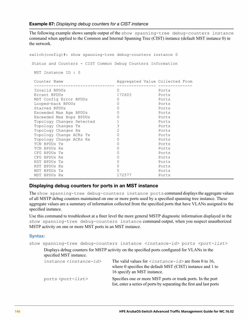
Example 87: Displaying debug counters for a CIST instance
The following example shows sample output of the show spanning-tree debug-counters instancecommand when applied to the Common and Internal Spanning Tree (CIST) instance (default MST instance 0) inthe network.
switch(config)#: show spanning-tree debug-counters instance 0
Status and Counters - CIST Common Debug Counters Information
MST Instance ID : 0
Counter Name Aggregated Value Collected From--------------------------------- ---------------- --------------Invalid BPDUs 0 PortsErrant BPDUs 172603 PortsMST Config Error BPDUs 0 PortsLooped-back BPDUs 0 PortsStarved BPDUs 0 PortsExceeded Max Age BPDUs 0 PortsExceeded Max Hops BPDUs 0 PortsTopology Changes Detected 1 PortsTopology Changes Tx 3 PortsTopology Changes Rx 2 PortsTopology Change ACKs Tx 0 PortsTopology Change ACKs Rx 0 PortsTCN BPDUs Tx 0 PortsTCN BPDUs Rx 0 PortsCFG BPDUs Tx 0 PortsCFG BPDUs Rx 0 PortsRST BPDUs Tx 0 PortsRST BPDUs Rx 0 PortsMST BPDUs Tx 5 PortsMST BPDUs Rx 172577 Ports
Displaying debug counters for ports in an MST instance
The show spanning-tree debug-counters instance ports command displays the aggregate valuesof all MSTP debug counters maintained on one or more ports used by a specified spanning tree instance. Theseaggregate values are a summary of information collected from the specified ports that have VLANs assigned to thespecified instance.
Use this command to troubleshoot at a finer level the more general MSTP diagnostic information displayed in theshow spanning-tree debug-counters instance command output, when you suspect unauthorizedMSTP activity on one or more MST ports in an MST instance.
Syntax:
show spanning-tree debug-counters instance <instance-id> ports <port-list>
Displays debug counters for MSTP activity on the specified ports configured for VLANs in thespecified MST instance.instance <instance-id> The valid values for <instance-id> are from 0 to 16,
where 0 specifies the default MST (CIST) instance and 1 to16 specify an MST instance.
ports <port-list> Specifies one or more MST ports or trunk ports. In the portlist, enter a series of ports by separating the first and last ports
146 HPE ArubaOS-Switch Advanced Traffic Management Guide for WC.16.02

in the series with a dash (-); for example, a2-a8 ortrk1-trk3. Separate individual ports and series of portswith a comma; for example, a2-a8, a20, trk1,trk4-trk5.
Example 88: Displaying debug counters for a CIST and MST instance
The following example shows sample output of the show spanning-tree debug-counters instanceports command for both the CIST (default MST instance 0) and an MST instance (instance 2) on port A15.
switch(config)#: show spanning-tree debug-counters instance 0 ports a15
Status and Counters - CIST Port(s) Debug Counters Information
MST Instance ID : 0Port : A15
Counter Name Value Last Updated--------------------------- ---------- -----------------Invalid BPDUs 0Errant BPDUs 0MST Config Error BPDUs 0Looped-back BPDUs 0Starved BPDUs 0Exceeded Max Age BPDUs 0Exceeded Max Hops BPDUs 0Topology Changes Detected 1 02/09/07 17:40:59Topology Changes Tx 3 02/09/07 17:41:03Topology Changes Rx 2 02/09/07 17:41:01Topology Change ACKs Tx 0Topology Change ACKs Rx 0TCN BPDUs Tx 0TCN BPDUs Rx 0CFG BPDUs Tx 0CFG BPDUs Rx 0RST BPDUs Tx 0RST BPDUs Rx 0MST BPDUs Tx 5 02/09/07 17:41:03MST BPDUs Rx 173540 02/13/07 18:05:34
Chapter 5 Multiple Instance Spanning Tree Operation 147

Example 89: Displaying debug counters output for one port in an MST instance
The following example shows spanning tree debug-counters instance ports command output for one port in an MSTinstance.
switch(config)#: show spanning-tree debug-counters instance 2 ports a15
Status and Counters - MSTI Port(s) Debug Counters Information
MST Instance ID : 2Port : A15
Counter Name Value Last Updated--------------------------- ---------- -----------------Starved MSTI MSGs 0Exceeded Max Hops MSTI MSGs 0Topology Changes Detected 1 02/09/07 17:40:59Topology Changes Tx 3 02/09/07 17:41:03Topology Changes Rx 2 02/09/07 17:41:01MSTI MSGs Tx 5 02/09/07 17:41:03MSTI MSGs Rx 173489 02/13/07 18:03:52
Field descriptions in MSTP debug command output
The following table contains descriptions of the debugging information displayed in the output of showspanning-tree debug-counters commands.
Table 11: MSTP debug command output: field descriptions
Displays the number of...Field
Received BPDUs that failed standardMSTP (802.1Q-REV/D5.0 14.4) validation checks andwere dropped. This counter is maintained by the CIST (default MST instance 0) on aper-port basis.
Invalid BPDUs
Received BPDUs that were dropped on a port that is configured to not expect BPDUpackets. This counter is maintained by the CIST (MST instance, 0default MST instance 0
Errant BPDUs
in the network) on a per-port basis and is incremented each time aBPDUpacket is receivedon a port configured with the BPDU filter to ignore incoming BPDU packets(spanning-tree bpdu-filter command) or the BPDU protection feature to disablethe port when BPDU packets are received (spanning-tree bpdu-protectioncommand).
BPDUs received froma neighbor bridgewith inconsistentMST configuration information.For example, BPDUs from a transmitting bridgemay contain the sameMST configuration
MST Config Error BPDUs
identifiers (region name and revision number) and format selector as the receiving bridge,but the value of the Configuration Digest field (VLAN ID assignments to regional IST andMST instances) is different. This difference indicates a probable configuration error inMST region settings on the communicating bridges. The received BPDU is still processedby MSTP.This counter is maintained by the CIST (default MST instance 0) on a per-port basis.
Times a port has received self-sent BPDUpackets as the result of an external loop conditionin which the BPDUs were looped back to the originating transmission port. The receivedBPDU is still processed by MSTP and the port changes to a blocked state.
Looped-back BPDUs
This counter is maintained by the CIST (default MST instance 0) on a per-port basis.
Times that no BPDUs are received within the scheduled interval (three times the HelloTime value configured with the spanning-tree hello-time command) from a
Starved BPDUs
148 HPE ArubaOS-Switch Advanced Traffic Management Guide for WC.16.02
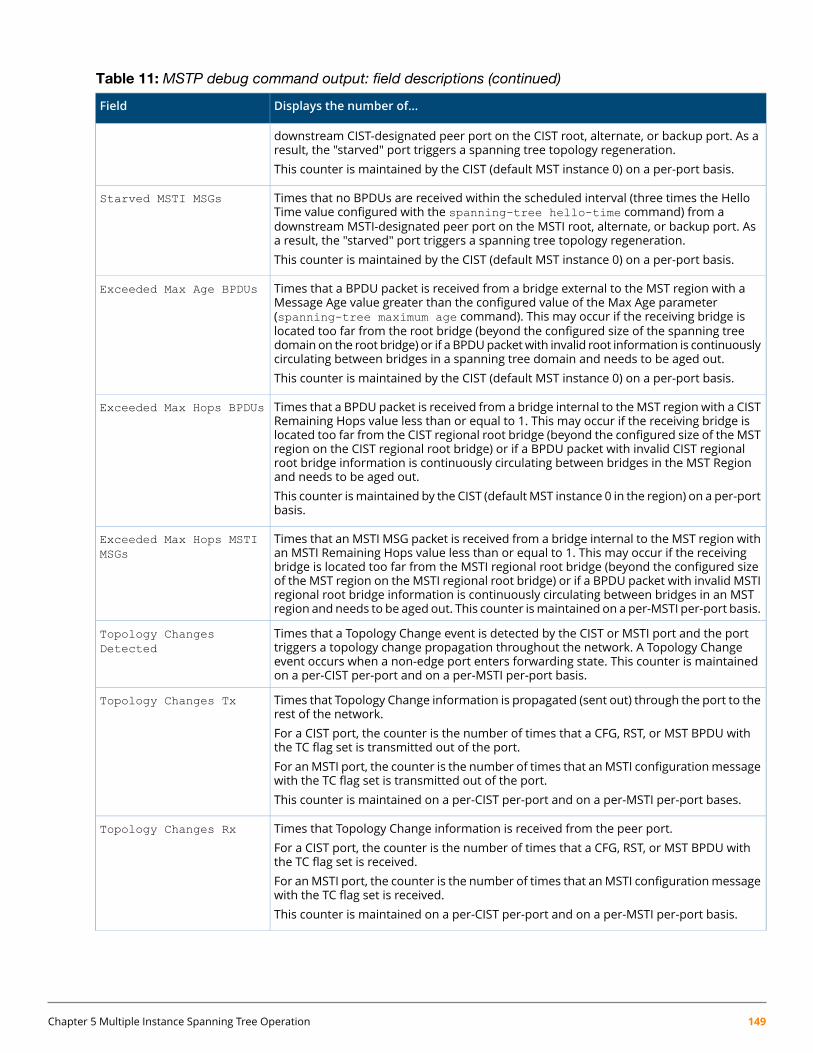
Table 11: MSTP debug command output: field descriptions (continued)
Displays the number of...Field
downstream CIST-designated peer port on the CIST root, alternate, or backup port. As aresult, the "starved" port triggers a spanning tree topology regeneration.This counter is maintained by the CIST (default MST instance 0) on a per-port basis.
Times that no BPDUs are received within the scheduled interval (three times the HelloTime value configured with the spanning-tree hello-time command) from a
Starved MSTI MSGs
downstream MSTI-designated peer port on the MSTI root, alternate, or backup port. Asa result, the "starved" port triggers a spanning tree topology regeneration.This counter is maintained by the CIST (default MST instance 0) on a per-port basis.
Times that a BPDU packet is received from a bridge external to the MST region with aMessage Age value greater than the configured value of the Max Age parameter
Exceeded Max Age BPDUs
(spanning-tree maximum age command). This may occur if the receiving bridge islocated too far from the root bridge (beyond the configured size of the spanning treedomain on the root bridge) or if a BPDUpacketwith invalid root information is continuouslycirculating between bridges in a spanning tree domain and needs to be aged out.This counter is maintained by the CIST (default MST instance 0) on a per-port basis.
Times that a BPDU packet is received from a bridge internal to theMST region with a CISTRemaining Hops value less than or equal to 1. This may occur if the receiving bridge is
Exceeded Max Hops BPDUs
located too far from the CIST regional root bridge (beyond the configured size of the MSTregion on the CIST regional root bridge) or if a BPDU packet with invalid CIST regionalroot bridge information is continuously circulating between bridges in the MST Regionand needs to be aged out.This counter ismaintained by the CIST (defaultMST instance 0 in the region) on a per-portbasis.
Times that an MSTI MSG packet is received from a bridge internal to the MST region withan MSTI Remaining Hops value less than or equal to 1. This may occur if the receiving
Exceeded Max Hops MSTIMSGs
bridge is located too far from the MSTI regional root bridge (beyond the configured sizeof the MST region on the MSTI regional root bridge) or if a BPDU packet with invalid MSTIregional root bridge information is continuously circulating between bridges in an MSTregion and needs to be aged out. This counter ismaintained on a per-MSTI per-port basis.
Times that a Topology Change event is detected by the CIST or MSTI port and the porttriggers a topology change propagation throughout the network. A Topology Change
Topology ChangesDetected
event occurs when a non-edge port enters forwarding state. This counter is maintainedon a per-CIST per-port and on a per-MSTI per-port basis.
Times that Topology Change information is propagated (sent out) through the port to therest of the network.
Topology Changes Tx
For a CIST port, the counter is the number of times that a CFG, RST, or MST BPDU withthe TC flag set is transmitted out of the port.For anMSTI port, the counter is the number of times that anMSTI configurationmessagewith the TC flag set is transmitted out of the port.This counter is maintained on a per-CIST per-port and on a per-MSTI per-port bases.
Times that Topology Change information is received from the peer port.Topology Changes Rx
For a CIST port, the counter is the number of times that a CFG, RST, or MST BPDU withthe TC flag set is received.For anMSTI port, the counter is the number of times that anMSTI configurationmessagewith the TC flag set is received.This counter is maintained on a per-CIST per-port and on a per-MSTI per-port basis.
Chapter 5 Multiple Instance Spanning Tree Operation 149

Table 11: MSTP debug command output: field descriptions (continued)
Displays the number of...Field
Times that the Topology Change acknowledgement is transmitted through the port(number of CFG, RST, or MST BPDUs transmitted with the Topology Change Acknowledge
Topology Change ACKs Tx
flag set). This counter is maintained by the CIST (default MST instance 0) on a per-portbasis.
Times the Topology Change acknowledgement is received on the port (number of CFG,RST, orMST BPDUs receivedwith the Topology Change Acknowledge flag set). This counteris maintained by the CIST (default MST instance 0) on a per-port basis.
Topology Change ACKs Rx
Topology Change Notification BPDUs that are transmitted through the port. This counteris maintained by the CIST (default MST instance 0) on a per-port basis.
TCN BPDUs Tx
Topology Change Notification BPDUs that are received on the port. This counter ismaintained by the CIST (default MST instance 0) on a per-port basis.
TCN BPDUs Rx
802.1D Configuration BPDUs that are transmitted through the port. This counter ismaintained by the CIST (default MST instance 0) on a per-port basis.
CFG BPDUs Tx
802.1D Configuration BPDUs that are received on the port. This counter maintained bythe CIST (default MST instance 0) on a per-port basis.
CFG BPDUs Rx
802.1w RST BPDUs that are transmitted through the port. This counter is maintained bythe CIST (default MST instance 0) on a per-port basis.
RST BPDUs Tx
802.1w RST BPDUs that are received on the port. This counter is maintained by the CIST(default MST instance 0) on a per-port basis.
RST BPDUs Rx
802.1s MST BPDUs that are transmitted through the port. This counter is maintained bythe CIST (default MST instance 0) on a per-port basis.
MST BPDUs Tx
802.1s MST BPDUs that are received on the port. This counter is maintained by the CIST(default MST instance 0) on a per-port basis.
MST BPDUs Rx
Times that a configuration message for a specific MSTI was encoded in (802.1s) MSTBPDUs that are transmitted through the port. This counter is maintained on a per-MSTIper-port basis.
MSTI MSGs Tx
Times that the MSTI detected a configuration message destined to the MSTI in (802.1s)MSTBPDUs received on the port. This counter ismaintained on a per-MSTI per-port basis.
MSTI MSGs Rx
Troubleshooting MSTP operation
Table 12: Troubleshooting MSTP operation
Possible causeProblem
The allocation of VLANs to MSTIs may not be identical among all switches ina region.
Duplicate packets on a VLAN, or packetsnot arriving on a LAN at all.
An MSTP switch intended for a particular region may not have the sameconfiguration nameor region revision number as the other switches intended
A switch intended to operate in a regiondoes not receive traffic fromother switchesin the region. for the same region. The MSTP configuration name (spanning-tree
config-name command) and MSTP configuration revision number(spanning-tree config-revision command) must be identical on allMSTP switches intended for the same region.Another possible cause is that the set of VLANs andVLAN ID-to-MSTImappings(spanning-tree instance vlan command) configuredon the switchmaynot match the set of VLANs and VLAN ID-to-MSTI mappings configured onother switches in the intended region.
150 HPE ArubaOS-Switch Advanced Traffic Management Guide for WC.16.02
About MSTP
Overview
For information on configuring RPVST+, see the rapid per-VLAN spanning tree operation chapter in this guide.
Without spanning tree, having more than one active path between a pair of nodes causes loops in the network, whichcan result in duplication of messages leading to a "broadcast storm" that can bring down the network.
MSTP cannot protect against loops when there is an unmanaged device on the network that drops spanningtree packets, ormay fail to detect loopswhere this is an edge port configuredwith client authentication (802.1X,Web, and MAC authentication). To protect against the formation of loops in these cases, you can use the loopprotection feature (see “Configuring loop protection” (page 134)).
Multiple-Instance spanning tree operation (802.1s) ensures that only one active path exists between any two nodesin a spanning tree instance. A spanning tree instance comprises a unique set of VLANs and belongs to a specificspanning tree region. A region can comprise multiple spanning tree instances (each with a different set of VLANs)and allows one active path among regions in a network. Applying VLAN tagging to the ports in a multiple-instancespanning tree network enables blocking of redundant links in one instance while allowing forwarding over the samelinks for non-redundant use by another instance.
Example 90: VLAN/Instance groupings
Suppose that there are three switches in a region configured with VLANs grouped into two instances, as follows:
Instance 2Instance 1VLANs
NoYes10, 11, 12
YesNo20, 21, 22
The logical and physical topologies resulting from these VLAN/Instance groupings result in blocking on differentlinks for different VLANs:
Chapter 5 Multiple Instance Spanning Tree Operation 151
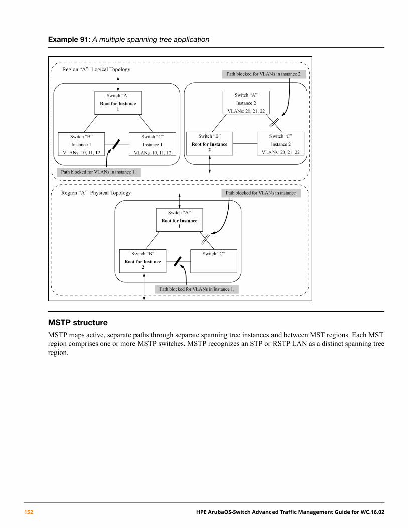
Example 91: A multiple spanning tree application
MSTP structure
MSTP maps active, separate paths through separate spanning tree instances and between MST regions. Each MSTregion comprises one or more MSTP switches. MSTP recognizes an STP or RSTP LAN as a distinct spanning treeregion.
152 HPE ArubaOS-Switch Advanced Traffic Management Guide for WC.16.02

Figure 21: An MSTP network with legacy STP and RSTP devices connected
How MSTP operates
In the factory default configuration, spanning tree operation is off. Also, the switch retains its currently configuredspanning tree parameter settings when disabled. Thus, if you disable spanning tree, then later re-enable it, theparameter settings will be the same as before spanning tree was disabled. The switch also includes a "Pending"feature that enables you to exchange MSTP configurations with a single command. (See “Enabling an entire MSTregion at once or exchanging one region configuration for another” (page 122).)
The switch automatically senses port identity and type and automatically defines spanning tree parametersfor each type, as well as parameters that apply across the switch. Although these parameters can be adjusted,Hewlett Packard Enterprise strongly recommends leaving these settings in their default configurations unlessthe proposed changes have been supplied by an experienced network administrator who has a strongunderstanding of the IEEE 802.1D/w/s standards and operation.
802.1s Multiple Spanning Tree Protocol (MSTP)
The switches covered in this guide use the IEEE 802.1s Multiple Spanning Tree Protocol (MSTP) standard.
The 802.1D and 802.1w spanning tree protocols operate without regard to a network's VLAN configuration andmaintain one common spanning tree throughout a bridged network. Thus, these protocols map one loop-free, logicaltopology on a given physical topology. The 802.1s Multiple Spanning Tree protocol (MSTP) uses VLANs to create
Chapter 5 Multiple Instance Spanning Tree Operation 153

multiple spanning trees in a network, which significantly improves network resource utilization while maintaininga loop-free environment.
While the per-VLAN spanning tree approach adopted by some vendors overcomes the network utilization problemsinherent in using STP or RSTP, using a per-VLAN technology with multiple VLANs can overload the switch's CPU.MSTP on the switches covered in this guide complies with the IEEE 802.1s standard and extends STP and RSTPfunctionality to map multiple independent spanning tree instances onto a physical topology. With MSTP, eachspanning tree instance can include one or more VLANs and applies a separate, per-instance forwarding topology.Thus, where a port belongs to multiple VLANs, it may be dynamically blocked in one spanning tree instance, butforwarding in another instance. This achieves load-balancing across the network while keeping the switch's CPUload at a moderate level (by aggregating multiple VLANs in a single spanning tree instance). MSTP provides faulttolerance through rapid, automatic reconfiguration if there is a failure in a network's physical topology.
With MSTP-capable switches, you can create a number of MST regions containing multiple spanning tree instances.This requires the configuration of a number of MSTP-capable switches. However, it is not necessary to do this. Youcan enable MSTP on an MSTP-capable switch and a spanning tree instance is created automatically. This instancealways exists by default when spanning tree is enabled and is the spanning tree instance that communicates withSTP and RSTP environments. The MSTP configuration commands operate exactly like RSTP commands and MSTPis backward-compatible with the RSTP-enabled and STP-enabled switches in your network.
Spanning tree interprets a switch mesh as a single link. Because the switch automatically gives faster links ahigher priority, the defaultMSTP parameter settings are usually adequate for spanning tree operation. Becauseincorrect MSTP settings can adversely affect network performance, do not change the MSTP settings fromtheir default values unless you have a strong understanding of how spanning tree operates.
In a mesh environment, the default MSTP timer settings (Hello Time and Forward Delay) are usually adequatefor MSTP operation. Because a packet crossing a mesh may traverse several links within the mesh, usingsmaller-than-default settings for the MSTP Hello Time and Forward Delay timers can cause unnecessarytopology changes and end-node connectivity problems.
For MSTP information beyond what is provided in this manual, see the IEEE 802.1s standard.
MST regions
All MSTP switches in a given region must be configured with the same VLANs and each MSTP switch within thesame region must have the same VLAN-to-instance assignments. In addition, a VLAN can belong to only oneinstance within any region. Within a region:
• All of the VLANs belonging to a given instance compose a single, active spanning tree topology for thatinstance.
• Each instance operates independently of other regions.
Between regions, there is a single, active spanning tree topology.
How separate instances affect MSTP
Assigning different groups of VLANs to different instances ensures that those VLAN groups use independentforwarding paths. For example, in Figure 22 (page 155) each instance has a different forwarding path.
154 HPE ArubaOS-Switch Advanced Traffic Management Guide for WC.16.02

Figure 22: Active topologies built by three independent MST instances
While allowing only one active path through a given instance, MSTP retains any redundant physical paths in theinstance to serve as backups (blocked) paths in case the existing active path fails. Thus, if an active path in an instancefails, MSTP automatically activates (unblocks) an available backup to serve as the newactive path through theinstance for as long as the original active path is down. Note also that a given port may simultaneously operate indifferent states (forwarding or blocking) for different spanning tree instances within the same region. This dependson the VLAN memberships to which the port is assigned. For example, if a port belongs to VLAN 1 in the ISTinstance of a region and also belongs to VLAN 4 in MSTI "x" in the same region, the port may apply different statesto traffic for these two different instances.
Within a region, traffic routed between VLANs in separate instances can take only one physical path. To ensure thattraffic in all VLANs within a region can travel between regions, all of the boundary ports for each region shouldbelong to all VLANs configured in the region. Otherwise, traffic from some areas within a region could be blockedfrom moving to other regions.
All MSTP switches (as well as STP and RSTP switches) in a network use BPDUs (Bridge Protocol Data Units) toexchange information from which to build multiple, active topologies in the individual instances within a regionand between regions. From this information:
• The MSTP switches in each LAN segment determine a designated bridge and designated port or trunk for thesegment.
• The MSTP switches belonging to a particular instance determine the root bridge and root port or trunk for theinstance.
• For the IST instance within a region, the MSTP switches linking that region to other regions (or to STP orRSTP switches) determine the IST root bridge and IST root port or trunk for the region. (For any Multiple
Chapter 5 Multiple Instance Spanning Tree Operation 155
spanning tree instance—MSTI—in a region, the regional root may be a different switch that is not necessarilyconnected to another region.)
• The MSTP switches block redundant links within each LAN segment, across all instances and between regions,to prevent any traffic loops.
As a result, each individual instance (spanning tree) within a region determines its regional root bridge, designatedbridges, and designated ports or trunks.
Regions, legacy STP, and RSTP switches and the Common Spanning Tree (CST)
The IST instance and any MST instances in a region exist only within that region. Where a link crosses a boundarybetween regions (or between a region and a legacy STP or RSTP switch), traffic is forwarded or blocked as determinedby the Common Spanning Tree (CST). The CST ensures that there is only one active path between any two regions,or between a region and a switch running STP and RSTP. (See Figure 21 (page 153).)
MSTP operation with 802.1Q VLANs
As indicated in the preceding sections, within a given MST instance, a single spanning tree is configured for allVLANs included in that instance. Thus if redundant physical links exist in separate VLANs within the same instance,MSTP blocks all but one of those links. However, you can prevent the bandwidth loss caused by blocked redundantlinks for different VLANs in an instance by using a port trunk. The following example shows how you can use aport trunk with 802.1Q (tagged) VLANs and MSTP without unnecessarily blocking any links or losing any bandwidth.
156 HPE ArubaOS-Switch Advanced Traffic Management Guide for WC.16.02
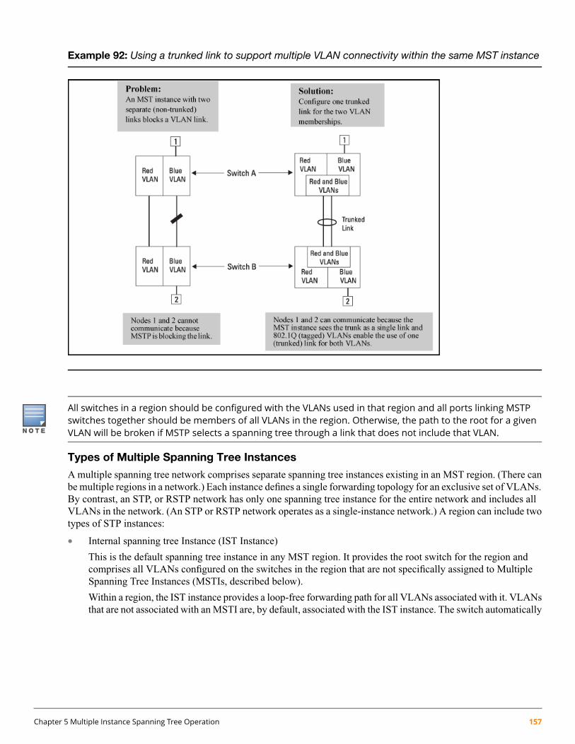
Example 92: Using a trunked link to support multiple VLAN connectivity within the same MST instance
All switches in a region should be configured with the VLANs used in that region and all ports linking MSTPswitches together should be members of all VLANs in the region. Otherwise, the path to the root for a givenVLAN will be broken if MSTP selects a spanning tree through a link that does not include that VLAN.
Types of Multiple Spanning Tree Instances
A multiple spanning tree network comprises separate spanning tree instances existing in an MST region. (There canbe multiple regions in a network.) Each instance defines a single forwarding topology for an exclusive set of VLANs.By contrast, an STP, or RSTP network has only one spanning tree instance for the entire network and includes allVLANs in the network. (An STP or RSTP network operates as a single-instance network.) A region can include twotypes of STP instances:
• Internal spanning tree Instance (IST Instance)
This is the default spanning tree instance in any MST region. It provides the root switch for the region andcomprises all VLANs configured on the switches in the region that are not specifically assigned to MultipleSpanning Tree Instances (MSTIs, described below).
Within a region, the IST instance provides a loop-free forwarding path for all VLANs associated with it. VLANsthat are not associated with an MSTI are, by default, associated with the IST instance. The switch automatically
Chapter 5 Multiple Instance Spanning Tree Operation 157
places dynamic VLANs (resulting from GVRP operation) in the IST instance. Dynamic VLANs cannot existin an MSTI (described below).
• Multiple Spanning Tree Instance (MSTI)
This type of configurable spanning tree instance comprises all static VLANs you specifically assign to it andmust include at least one VLAN. The VLANs you assign to an MSTI must initially exist in the IST instanceof the same MST region. When you assign a static VLAN to an MSTI, the switch removes the VLAN fromthe IST instance. (Thus, you can assign a VLAN to only one MSTI in a given region.) All VLANs in an MSTIoperate as part of the same single spanning tree topology. (The switch does not allow dynamic VLANs in anMSTI.)
When you enable MSTP on the switch, the default MSTP spanning tree configuration settings comply with thevalues recommended in the IEEE 802.1s Multiple Spanning Tree Protocol (MSTP) standard. Inappropriatechanges to these settings can result in severely degraded network performance. For this reason, HewlettPackard Enterprise strongly recommends that changing these default settings be reserved only for experiencednetwork administrators who have a strong understanding of the IEEE 802.1D/w/s standards and operation.
Operating rules
• All switches in a region must be configured with the same set of VLANs, as well as the same MST configurationname and MST configuration number.
• Within a region, a VLAN can be allocated to either a single MSTI or to the region's IST instance.
• All switches in a region must have the same VID-to-MST instance assignment.
• There is one root MST switch per configured MST instance.
• Because boundary ports provide the VLAN connectivity between regions, all boundary ports on a region's rootswitch should be configured as members of all static VLANs defined in the region.
• There is one root switch for the Common and Internal Spanning Tree (CIST). At any given time, all switchesin the network will use the per-port hello-time parameter assignments configured on the CIST root switch.
• Where multiple MST regions exist in a network, there is only one active, physical communication path betweenany two regions, or between an MST region and an STP or RSTP switch. MSTP blocks any other physicalpaths as long as the currently active path remains in service.
• Within a network, an MST region appears as a virtual RSTP bridge to other spanning tree entities (other MSTregions and any switches running 802.1D or 802.1w spanning tree protocols).
• Within an MSTI, there is one physical communication path between any two nodes, regardless of how manyVLANs belong to the MSTI. Within an IST instance, there is also one spanning tree across all VLANs belongingto the IST instance.
• An MSTI comprises a unique set of VLANs and forms a single spanning tree instance within the region towhich it belongs.
• A dynamic VLAN learned by GVRP will always be placed in the IST instance and cannot be moved to anyconfigured MST instance.
Dynamically learned GVRP VLANs can be mapped to MSTIs and support MSTP load balancing.
• You can preconfigure static and dynamic VLAN ID-to-MSTI mappings before the VLAN is created on theswitch. Later, when the static VLAN ID is configured or a dynamic GVRP VLAN is learned, the VLAN is
158 HPE ArubaOS-Switch Advanced Traffic Management Guide for WC.16.02

automatically associated with the preconfigured MSTI. For more information, see “Configuring MST instanceparameters” (page 118).
• Communication between MST regions uses a single spanning tree.
• If a port on a switch configured for MSTP receives a legacy (STP/802.1D or RSTP/802.1w) BPDU, itautomatically operates as a legacy port. In this case, the MSTP switch interoperates with the connected STPor RSTP switch as a separate MST region.
• Within an MST region, there is one logical forwarding topology per instance and each instance comprises aunique set of VLANs. Where multiple paths exist between a pair of nodes using VLANs belonging to the sameinstance, all but one of those paths will be blocked for that instance. However, if there are different paths indifferent instances, all such paths are available for traffic. Separate forwarding paths exist through separatespanning tree instances.
• A port can have different states (forwarding or blocking) for different instances (which represent differentforwarding paths).
• MSTP interprets a switch mesh as a single link.
Operating notes for the VLAN configuration enhancement
• Configuring MSTP on the switch automatically configures the Internal Spanning Tree (IST) instance and placesall statically and dynamically configured VLANs on the switch into the IST instance. The spanning tree instancevlan command creates a new MST instance and moves the VLANs you specify from the IST to the MSTI.
You must map a least one VLAN ID to an MSTI when you create it. You cannot map a VLAN ID to more thanone instance. You can create up to 16 MSTIs in a region.
• The no form of the spanning tree instance vlan command removes one or more VLANs from the specifiedMSTI. If no VLANs are specified, the no form of the command deletes the specified MSTI.
When you remove a VLAN from an MSTI, the VLAN returns to the IST instance, where it can remain or bereassigned to another MSTI configured in the region.
• If you enter the spanning tree instance vlan command before a static or dynamic VLAN is configured on theswitch to preconfigure VLAN ID-to-MSTI mappings, no error message is displayed. Later, each newly configuredVLAN that has already been associated with an MSTI is automatically assigned to the MSTI.
This new default behavior differs from automatically including configured (static and dynamic) VLANs in theIST instance and requiring you to manually assign individual static VLANs to an MSTI.
• Valid VLAN IDs that you can map to a specified MSTI are numbered from 1 to 4094. The VLAN ID-to-MSTImapping does not require a VLAN to be already configured on the switch. The MSTP VLAN enhancementlets you preconfigure MSTP topologies before the VLAN IDs associated with each instance exist on a switch.
• When you use preconfigured VLAN ID-to-MSTI topologies, ensure that MSTP switches remain in the sameregion by mapping all VLAN IDs used in the region to the same MSTIs on each regional switch.
• The existing MSTP topology configuration is automatically saved. All existing VLAN ID-to-MSTI assignmentsare maintained on a switch for uninterrupted MSTP network operation.
MSTP compatibility with RSTP or STP
IEEE 802.1s MSTP includes RSTP functionality and is designed to be compatible with both IEEE 802.1D and802.1w spanning tree protocols. Using the default configuration values, your switches will interoperate effectivelywith RSTP and STP devices. MSTP automatically detects when the switch ports are connected to non-MSTP devicesin the spanning tree and communicates with those devices using 802.1D or 802.1w STP BPDU packets, as appropriate.
Chapter 5 Multiple Instance Spanning Tree Operation 159
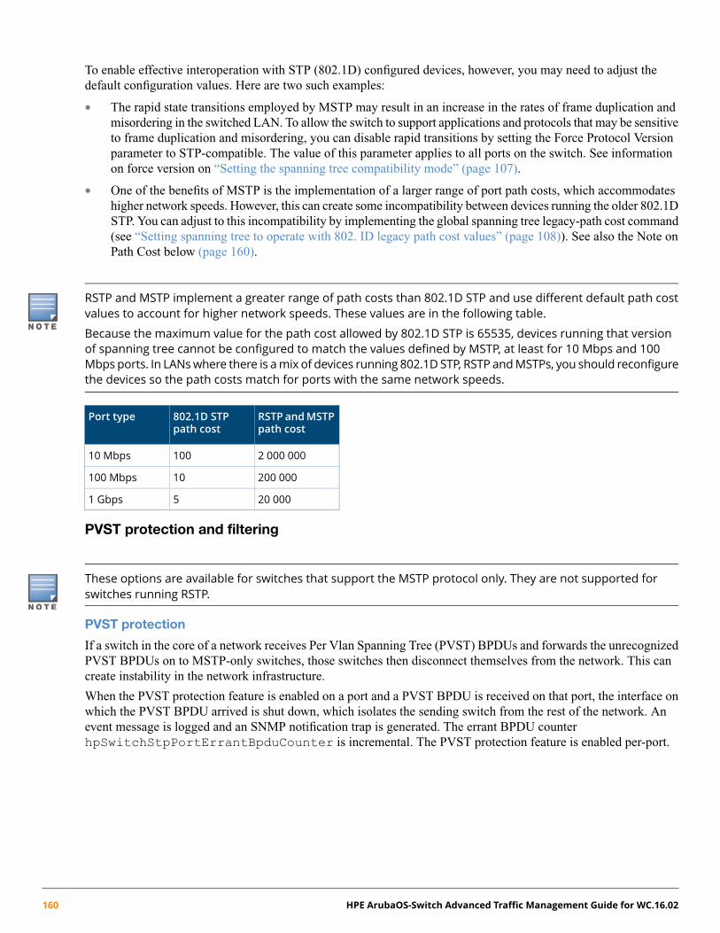
To enable effective interoperation with STP (802.1D) configured devices, however, you may need to adjust thedefault configuration values. Here are two such examples:
• The rapid state transitions employed by MSTP may result in an increase in the rates of frame duplication andmisordering in the switched LAN. To allow the switch to support applications and protocols that may be sensitiveto frame duplication and misordering, you can disable rapid transitions by setting the Force Protocol Versionparameter to STP-compatible. The value of this parameter applies to all ports on the switch. See informationon force version on “Setting the spanning tree compatibility mode” (page 107).
• One of the benefits of MSTP is the implementation of a larger range of port path costs, which accommodateshigher network speeds. However, this can create some incompatibility between devices running the older 802.1DSTP. You can adjust to this incompatibility by implementing the global spanning tree legacy-path cost command(see “Setting spanning tree to operate with 802. ID legacy path cost values” (page 108)). See also the Note onPath Cost below (page 160).
RSTP and MSTP implement a greater range of path costs than 802.1D STP and use different default path costvalues to account for higher network speeds. These values are in the following table.
Because the maximum value for the path cost allowed by 802.1D STP is 65535, devices running that versionof spanning tree cannot be configured to match the values defined by MSTP, at least for 10 Mbps and 100Mbps ports. In LANswhere there is amix of devices running 802.1D STP, RSTP andMSTPs, you should reconfigurethe devices so the path costs match for ports with the same network speeds.
RSTP andMSTPpath cost
802.1D STPpath cost
Port type
2 000 00010010 Mbps
200 00010100 Mbps
20 00051 Gbps
PVST protection and filtering
These options are available for switches that support the MSTP protocol only. They are not supported forswitches running RSTP.
PVST protection
If a switch in the core of a network receives Per Vlan Spanning Tree (PVST) BPDUs and forwards the unrecognizedPVST BPDUs on to MSTP-only switches, those switches then disconnect themselves from the network. This cancreate instability in the network infrastructure.
When the PVST protection feature is enabled on a port and a PVST BPDU is received on that port, the interface onwhich the PVST BPDU arrived is shut down, which isolates the sending switch from the rest of the network. Anevent message is logged and an SNMP notification trap is generated. The errant BPDU counterhpSwitchStpPortErrantBpduCounter is incremental. The PVST protection feature is enabled per-port.
160 HPE ArubaOS-Switch Advanced Traffic Management Guide for WC.16.02

Figure 23: PVST switch being isolated after sending a PVST BPDU
This is similar to the BPDUGuard featurewhere BPDUprotection is applied to edge ports connected to end-userdevices that do not run STP. If STP BPDU packets are received on a protected port, the feature will disable thatport and alert the network manager via an SNMP trap.
PVST filtering
If you configure a port for PVST filtering instead of PVST protection, the port remains in operation but traps arestill generated and the BPDU counter hpSwitchStpPortErrantBpduCounter is incremented.
Enabling the PVST filter feature allows the port to continuously forward packets without spanning treeintervention, which could result in loop formation. If this occurs, disable the port and then reconfigure it withthese commands:
no spanning-tree <port-list> bpdu-filter
no spanning-tree <port-list> pvst-filter
Loop protection
In cases where spanning tree cannot be used to prevent loops at the edge of the network, loop protection may providea suitable alternative. Loop protection operates in two modes:
Untagged The default mode. This mode can be used to find loops in untagged downlinks.
Tagged VLAN Finds loops on tagged VLANs. This mode can be used to detect loops in tagged-only uplinkswhere STP cannot be enabled.
The cases where loop protection might be chosen ahead of spanning tree to detect and prevent loops are as follows:
On ports with client authentication When spanning tree is enabled on a switch that use 802.1X, Webauthentication and MAC authentication, loops may go undetected. Forexample, spanning tree packets that are looped back to an edge port willnot be processed because they have a different broadcast/multicast MACaddress from the client-authenticated MAC address. To ensure thatclient-authenticated edge ports get blocked when loops occur, you shouldenable loop protection on those ports.
On ports connected to unmanageddevices
Spanning tree cannot detect the formation of loops where there is anunmanaged device on the network that does not process spanning tree
Chapter 5 Multiple Instance Spanning Tree Operation 161

packets and simply drops them. Loop protection has no such limitationand can be used to prevent loops on unmanaged switches.
Example 93: Loop protection enabled in preference to STP
Operating notes
• The receiver-action option can be configured on a per-port basis and can only be enabled after loopprotection has been enabled on the port. All other configuration options (disable-timer, trap loop-detected andtransmit interval) are global.
• The trap option refers to an SNMP trap.
• Regardless of how the receiver-action and trap options are configured, all detected loops will belogged in the switch's event log.
• Theno loop-protect portcommand will not remove a receive-action configuration line from the running configuration unless this optionis set to receive-action send-disable.
• If loop-protect is enabled in port mode, it cannot also be enabled in VLAN mode and vice-versa.
162 HPE ArubaOS-Switch Advanced Traffic Management Guide for WC.16.02
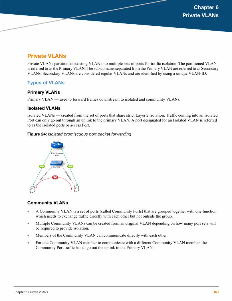
Chapter 6
Private VLANs
Private VLANsPrivate VLANs partition an existing VLAN into multiple sets of ports for traffic isolation. The partitioned VLANis referred to as the Primary VLAN. The sub domains separated from the Primary VLAN are referred to as SecondaryVLANs. Secondary VLANs are considered regular VLANs and are identified by using a unique VLAN-ID.
Types of VLANs
Primary VLANs
Primary VLAN — used to forward frames downstream to isolated and community VLANs.
Isolated VLANs
Isolated VLANs — created from the set of ports that share strict Layer 2 isolation. Traffic coming into an IsolatedPort can only go out through an uplink to the primary VLAN. A port designated for an Isolated VLAN is referredto as the isolated ports or access Port.
Figure 24: Isolated promiscuous port packet forwarding
Community VLANs
• A Community VLAN is a set of ports (called Community Ports) that are grouped together with one functionwhich needs to exchange traffic directly with each other but not outside the group.
• Multiple Community VLANs can be created from an original VLAN depending on how many port sets willbe required to provide isolation.
• Members of the Community VLAN can communicate directly with each other.
• For one Community VLAN member to communicate with a different Community VLAN member, theCommunity Port traffic has to go out the uplink to the Primary VLAN.
Chapter 6 Private VLANs 163

Figure 25: Community promiscuous port packet forwarding
PVLAN port types
Promiscuous port
A promiscuous port is an upstream tagged/untagged port connected to a router, firewall, or provider network. Apromiscuous port can communicate with all ports, including the isolated and community VLAN member ports withina PVLAN. By default all primary VLAN member ports acts as promiscuous port.
Community/Isolated Access Port
Community ports communicate among themselves and with their promiscuous ports and PVLAN member port.These ports are separated at Layer 2 from all other ports in other communities or isolated ports within their PVLAN.
Isolated ports have Layer 2 connectivity only with promiscuous ports and PVLAN member ports. An isolated accessport cannot communicate with another isolated port even if the two ports are members of the same isolated VLAN.
Community/Isolated ports must be untagged on 2920 switches. On other platforms (5400, 3800, 5400R and3810), the access ports can be either untagged or tagged members.
PVLAN member port (Also called Interswitch Link [ISL] ports)
A PVLAN member port (ISL port) is required in multi-switch PVLAN configurations to span the switches. ThePVLAN member port will automatically become a member of all VLANs within the PVLAN (that is, the primaryVLAN, the community VLANs and the isolated VLAN), and it carries traffic from the primary VLAN and allsecondary VLANs.
A primary VLAN port can either act as a promiscuous port or PVLAN member port (ISL port). By default, theprimary VLAN port acts as promiscuous port. To make it as PVLAN member port (or ISL port), un-configure theport as promiscuous port from interface context.
Private VLANs across multiple switches
Consider a network topology where Secondary VLANs have been configured on a set of access switches but onlyone of these switches has uplink connectivity. The Secondary VLAN traffic on switches that do not have an uplinkconfigured have to go through multiple switching hops to the device that has an uplink connection. As SecondaryVLAN traffic traverses Interswitch links, Private VLAN traffic forwarding rules must be preserved on all accessswitches in the path that are configured for Private VLANs.
164 HPE ArubaOS-Switch Advanced Traffic Management Guide for WC.16.02

For example, on an Isolated VLAN, traffic originating on one switch without a Promiscuous port would be forwardedout the Interswitch link to the next access switch. This traffic would be routed switch to switch until it is forwardedto a switch with a Promiscuous port. Each switch in the path must understand that the traffic belongs to an IsolatedVLAN and therefore not forward the traffic to any local Community ports. To accomplish this, the VLAN informationmust be preserved as the traffic traverses the Interlink switches. This can be done with Secondary VLAN informationcarried in the frame (VLAN tags).
Extending the scope of a Private VLAN beyond a single switch gives you a uniform way of partitioning a VLANacross all switches that have been configured with that VLAN.
Figure 26: Interswitch link forwarding
PVLAN Ports and Layer 2 connectivity
SecondaryIsolateAccess
SecondaryCommunityAccess
PVLANMemberPort
PromiscuousIN –{PORT,VID}/OUT
YesYesYesYes{Promiscuous,Primary VID}
YesYesYesYes{Member Port,Primary VID}
NoYes – SamecommunityVLAN only
YesYes{Member Port,Secondary VID}
NoYes - SamecommunityVLAN only
YesYes{SecondaryCommunity,Secondary VID}
NoNoYesYes{Secondary Isolate,Secondary Vid}
IP address assignmentSecondary VLANs are Layer 2 VLANs without individual IP or subnet addresses. If a Primary VLAN is associatedwith an IP subnet, then that subnet will automatically extend to all Secondary VLANs members of that PrimaryVLAN.
Chapter 6 Private VLANs 165

PVLAN Interaction with Other FeaturesVLAN features fall into one of the four PVLAN configuration categories shown below.
Table 13: PVLAN configuration categories
NotesC#
Categories
The said feature can operate independently on Secondary VLANs versusPrimary VLANs. There is no customer use-case or benefit of enabling themtogether.
C1Configuration Consistency Not Required(CCNR)
The Primary VLAN settings must be extended to the Secondary VLANs.C2Configuration Consistency Enforced (CCE) The said feature’s configuration will be disallowed On Secondary VLANs
and the configuration on the Primary VLAN will automatically be appliedto Secondary VLANs.
It is recommended that the same configuration be applied to Primary andSecondary VLANs but PVLAN can continue to function although in partialor suboptimal ways.
C3Configuration Consistency Recommended(CCR)
The said feature is not allowed on the private-vlans, both primary andsecondary.
C4Configuration Not Allowed (CNA)
The actual features and the categories they belong to are listed in the table below.
Table 14: Feature to category mapping
CNACCRCCECCNRConfigurations Not AllowedConfiguration Consistency
RecommendedConfiguration ConsistencyEnforced
ConfigurationConsistencyNot Required
Primary-vlanQoSDHCP SnoopingVirus ThrottlingManagement-vlanDST-IP, L4-7 ACLDHCPv6 SnoopingMonitorProtocol-vlanDST-IP, L4-7 Policy Based
MirrorRA GuardVLAN-Name
PVSTND SnoopingSRC-IP ACL (Ingress)lldp radio portsVoiceDARPPSRC-IP Policy BasedMirrorOut MirroringStatic-MACDIPLD v4/v6UDLDDistributed trunkingIGMP SnoopLoop-protectGVRP/MVRPMLD SnoopMeshingIPv4/v6 AddressQinQNDVLAN source filteringIP Directed Broadcast, DHCP
Relay, UDP-broadcast-fwd Local-proxy ARPDisable-Layer3 Proxy ARPJumbo-MTUDHCP ServerIP-Recv-MACVRRPIRDPBGPOSPFOSPF3RIPMSTP vlan-instance mapSmartlink
166 HPE ArubaOS-Switch Advanced Traffic Management Guide for WC.16.02
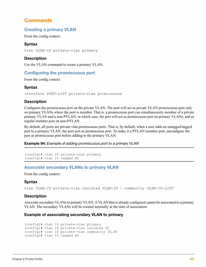
Commands
Creating a primary VLANFrom the config context:
Syntax
vlan VLAN-ID private-vlan primary
Description
Use the VLAN command to create a primary VLAN.
Configuring the promiscuous portFrom the config context:
Syntax
interface PORT-LIST private-vlan promiscuous
Description
Configures the promiscuous port on the private VLAN. The port will act as private VLAN promiscuous port onlyon primary VLANs where the port is member. That is, a promiscuous port can simultaneously member of a privateprimary VLAN and a non-PVLAN, in which case, the port will act as promiscuous port on primary VLANs, and asregular member port on non-PVLAN.
By default, all ports are private-vlan promiscuous ports. That is, by default, when a user adds an untagged/taggedport to a primary VLAN, the port acts as promiscuous port. To make it a PVLAN member port, unconfigure theport as promiscuous port before adding to the primary VLAN.
Example 94: Example of adding promiscuous port to a primary VLAN
(config)# vlan 10 private-vlan primary(config)# vlan 10 tagged A2
Associate secondary VLANs to primary VLANFrom the config context:
Syntax
vlan VLAN-ID private-vlan isolated VLAN-ID | community VLAN-ID-LIST
Description
Associate secondary VLANs to primary VLAN. A VLAN that is already configured cannot be associated to a primaryVLAN. The secondary VLANs will be created internally at the time of association.
Example of associating secondary VLAN to primary
(config)# vlan 10 private-vlan primary(config)# vlan 10 private-vlan isolated 20(config)# vlan 10 private-vlan community 30,40(config)# vlan 10 tagged A2
Chapter 6 Private VLANs 167

(int A3)# no private-vlan promiscuous(config)# vlan 10 tagged A3
In the above example, port A3 is a PVLANmember port and automatically becomesmember port of all associatedsecondary VLAN.
Remove the secondary VLANs configuration
Syntax
From within the config context:
[no] vlan VLAN-ID private-vlan isolated VLAN-ID | community VLAN-ID-LIST
Description
Remove the secondary VLANs configuration. It will remove the VLANs also.
Changing a port from promiscuous port to PVLAN member port
Syntax
From within the config context:
[no]interface PORT-LIST private-vlan promiscuous
Description
Changes port type from promiscuous to PVLAN member port.
Example 95: Adding a PVLAN member port
(int a3)# no private-vlan promiscuous(config)# vlan 10 private-vlan primary(config)# vlan 10 tagged a3
Change the primary VLAN to normal VLAN
Syntax
From within the config context:
[no] vlan VLAN-ID private-vlan primary
Description
Change the primary VLAN to normal VLAN
Adding a secondary VLAN
Syntax
From the config context:
vlan VLAN-ID private-vlan isolated VLAN-ID | community VLAN-ID-LIST
168 HPE ArubaOS-Switch Advanced Traffic Management Guide for WC.16.02

Description
Use this command to add a secondary VLAN. Secondary VLANs will be created internally. Existing VLANs cannotbe configured as secondary VLANs.
Removing a secondary VLAN
Syntax
From within the config context:
[no]vlan VLAN-ID private-vlan isolated VLAN-ID | community VLAN-ID-LIST
Description
Use this command to remove the association of the secondary VLAN to a primary VLAN.
Changing a port from promiscuous port to PVLAN member port
Syntax
From within the config context:
[no]interface PORT-LIST private-vlan promiscuous
Description
Changes port type from promiscuous to PVLAN member port.
Example 96: Adding PVLAN member port
(int a3)# no private-vlan promiscuous(config)# vlan 10 private-vlan primary(config)# vlan 10 tagged a3
Change the primary VLAN to normal VLAN
Syntax
[no] vlan VLAN-ID private-vlan primary
Description
Change the primary VLAN to normal VLAN.
Configuring Private VLANs
Configuring private VLAN settings
Syntax
[no]vlan VLAN-ID private-vlan primary |isolated VLAN-ID| community VLAN-ID-LIST
Description
Use this command to configure private VLAN settings.
private-vlan Configure private VLAN settings.
isolated Configure the isolated VLAN ID for this private VLAN.
Chapter 6 Private VLANs 169
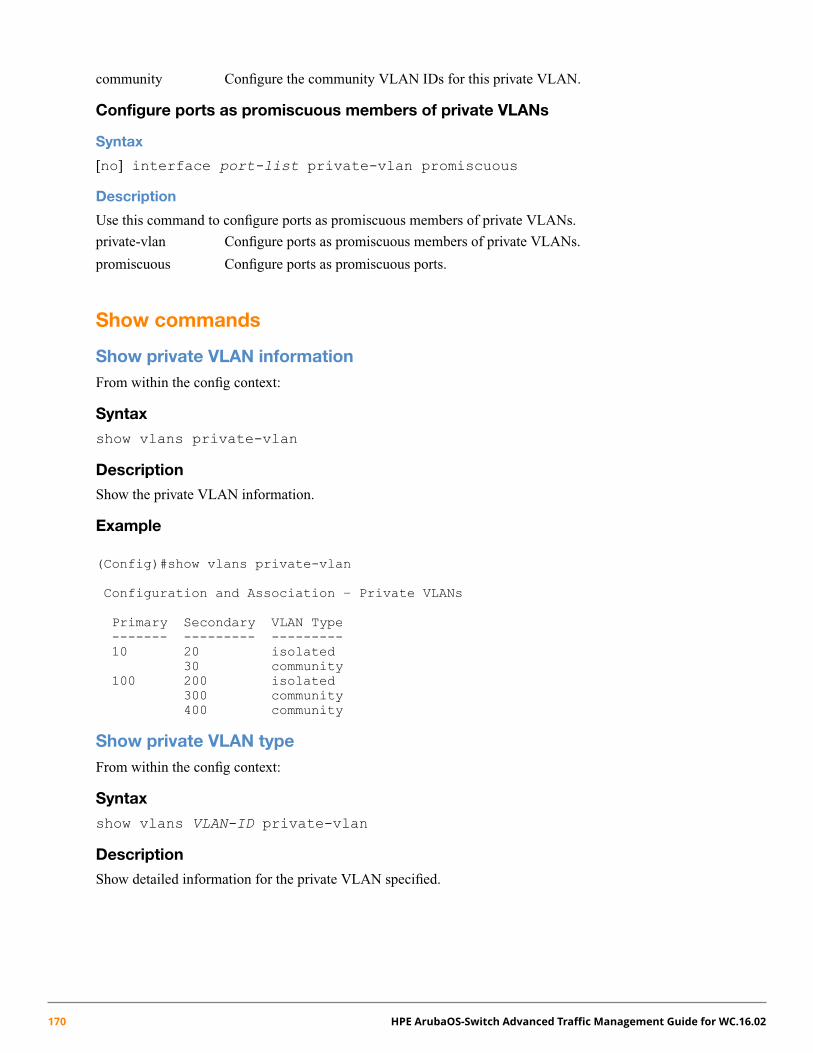
community Configure the community VLAN IDs for this private VLAN.
Configure ports as promiscuous members of private VLANs
Syntax
[no] interface port-list private-vlan promiscuous
Description
Use this command to configure ports as promiscuous members of private VLANs.
private-vlan Configure ports as promiscuous members of private VLANs.
promiscuous Configure ports as promiscuous ports.
Show commands
Show private VLAN informationFrom within the config context:
Syntax
show vlans private-vlan
Description
Show the private VLAN information.
Example
(Config)#show vlans private-vlan
Configuration and Association – Private VLANs
Primary Secondary VLAN Type------- --------- ---------10 20 isolated
30 community100 200 isolated
300 community400 community
Show private VLAN typeFrom within the config context:
Syntax
show vlans VLAN-ID private-vlan
Description
Show detailed information for the private VLAN specified.
170 HPE ArubaOS-Switch Advanced Traffic Management Guide for WC.16.02

Example 97: Show vlans 100 private-vlan
(config)# show vlans 100 private-vlan
Private VLAN Configuration Information: VLAN 100 VLAN Type : primary
Port Type Ports------------ ----Promiscuous A1Member A3,A5
Associated Secondary VLANs:
VLAN-ID VLAN type Access Ports------- --------- ------------20 isolated A2,A3,A530 community F4,F5,A3,A5
Example 98: Show vlans 20 private-vlan
(config)# show vlans 20 private-vlan
Private VLAN Configuration Information: VLAN 20VLAN Type : community or isolated Access ports : A1,A3,A4Associated Primary VLAN: 100
Port Type Port----------- ----Member A1Promiscuous A2
Show private VLAN and its port mode
Syntax
show vlans private-vlan promiscuous-ports
Description
Show the promiscuous ports mapped to the primary VLANs.
private-vlan Show the promiscuous ports mapped to the primary VLANs.
promiscuous-ports Show information about the promiscuous ports on primary VLANs.
Chapter 6 Private VLANs 171

Example 99: Show private-vlan promiscuous-ports
(config)# show private-vlan promiscuous-ports
primary VLAN Port------------- ------10 A1100 A2
Show dhcp-snooping binding private-vlan
Syntax
Show dhcp-snooping binding private-vlan
Description
Show dhcp-snooping binding private-vlan.
Modifying existing commandsThe following commands are modified as a result of this feature:
• show vlans
• show running-config
• show dhcp-snooping binding
• show tech all
Show VLANs
Syntax
show vlans
Description
Command output has been modified to show PVLAN information if configured.
Example if VLAN is not configured
(config)# show vlans 1VLAN ID : 100Name : DEFAULT_VLANStatus : Port-basedVoice : NoJumbo : No
Port Information Mode Unknown VLAN Status------------------ ------- -------------- --------C1 Untagged Learn Up
Example when private VLAN is configured
(config)# show vlans 101
172 HPE ArubaOS-Switch Advanced Traffic Management Guide for WC.16.02
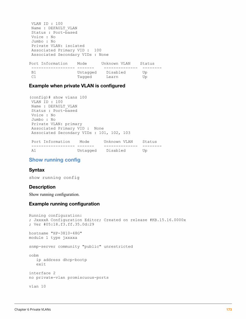
VLAN ID : 100Name : DEFAULT_VLANStatus : Port-basedVoice : NoJumbo : NoPrivate VLAN: isolatedAssociated Primary VID : 100Associated Secondary VIDs : None
Port Information Mode Unknown VLAN Status------------------ ------- -------------- --------B1 Untagged Disabled UpC1 Tagged Learn Up
Example when private VLAN is configured
(config)# show vlans 100VLAN ID : 100Name : DEFAULT_VLANStatus : Port-basedVoice : NoJumbo : NoPrivate VLAN: primaryAssociated Primary VID : NoneAssociated Secondary VIDs : 101, 102, 103
Port Information Mode Unknown VLAN Status------------------ ------- -------------- --------A1 Untagged Disabled Up
Show running config
Syntax
show running config
Description
Show running configuration.
Example running configuration
Running configuration:; JxxxxA Configuration Editor; Created on release #KB.15.16.0000x; Ver #05:18.f3.ff.35.0d:29
hostname "HP-3810-48G"module 1 type jxxxxa
snmp-server community "public" unrestricted
oobmip address dhcp-bootpexit
interface 2no private-vlan promiscuous-ports
vlan 10
Chapter 6 Private VLANs 173

name "DEFAULT_VLAN"untagged 1-9private-vlan primaryprivate-vlan isolated 100private-vlan community 101ip address dhcp-bootpexitvlan 100name "DEFAULT_VLAN"untagged 10exit
vlan 101name "DEFAULT_VLAN"untagged 11exit
Show dhcp-snooping binding
Syntax
show dhcp-snooping binding
Description
Show the dhcp-snooping binding with the associated VLANs.
Usage
show dhcp-snooping binding
Output
MacAddress IP VLAN Interface Time Left---------–- -------- ------ ----------- -- -----
Usage
show dhcp-snooping binding private-vlan
Output
MacAddress IP VLAN Interface Time Left Secondary VLAN---------- -------- ----- -------- --------- --------------
Usage
show dhcpv6-snooping binding
Output
MACAddress IPv6-Address VLAN Port Time Left---------- ------------ ----- ---- ---------
Usage
show dhcpv6-snooping binding private-vlan
174 HPE ArubaOS-Switch Advanced Traffic Management Guide for WC.16.02

Output
MAC Address IPv6-Address VLAN Port Time Left Secondary VLAN----------- ------------ ---- ---- --------- --------------
Show tech all
Syntax
show tech all
Description
The following section will be added to the existing output of the show tech all command.
Added to the output of show tech all
Show vlans private-vlan(config)# Show tech all
Show vlans private-vlanprimary secondary Type Ports------- --------- -------------- -------------10 20 isolated A1,A2,A3
30 community A1,A4,A5100 200 isolated B1,B2,B3
300 community B1,B2,B4
show private-vlan promiscuous-ports
Port Private-VLAN Mapping primary secondary------ -------------------- ------- --------A1 10 20, 30B1 100 200, 300
Validations, errors, and restrictions
Validation rules
Warning/Error messageTrigger
IGMP snooping cannot be configured on asecondary VLAN. It should be configured on the
Configuring IGMP snoopingon secondary VLAN
primary VLAN and will automatically apply to allsecondary VLANs associated with that primaryVLAN.
MLD cannot be configured on a secondary VLAN.It should be configured on the primary VLAN and
Configuring MLD onsecondary VLAN
will automatically apply to all secondary VLANsassociated with that primary VLAN.
DHCP snooping cannot be configured on asecondary VLAN. It should be configured on the
Configuring DHCP snoopingon secondary VLAN
primary VLAN and will automatically apply to all
Chapter 6 Private VLANs 175

Warning/Error messageTrigger
secondary VLANs associated with that primaryVLAN.
DHCPv6 snooping cannot be configured on asecondary VLAN. It should be configured on the
Configuring DHCPv6snooping on secondary VLAN
primary VLAN and will automatically apply to allsecondary VLANs associated with that primaryVLAN.
IP source binding cannot be configured on asecondary VLAN. It should be configured on the
Configuring IP Static bindingon a secondary VLAN
primary VLAN and will automatically apply to allsecondary VLANs associated with that primaryVLAN.
IPv6 source binding cannot be configured on asecondary VLAN. It should be configured on the
Configuring IPv6 Staticbinding on a secondary VLAN
primary VLAN and will automatically apply to allsecondary VLANs associated with that primaryVLAN.
Jumbo frames cannot be configured on asecondary VLAN. The jumbo frames should be
Configuring Jumbo frames onsecondary VLAN
configured on the primary VLAN and willautomatically apply to all secondary VLANsassociated with that primary VLAN.
DHCP relay cannot be configured on a secondaryVLAN. It should be configured on the primary VLAN
Configuring DHCP Relay onsecondary VLAN
andwill automatically apply to all secondary VLANsassociated with that primary VLAN.
UDP forwarder cannot be configured on asecondary VLAN. It should be configured on the
Enabling UDP Forwarder onsecondary VLAN
primary VLAN and will automatically apply to allsecondary VLANs associated with that primaryVLAN.
GVRP cannot be enabled when a private VLAN isconfigured.
Enabling GVRP on the switchWhen private VLAN’s areconfigured
GVRP cannot be enabled when a private VLAN isconfigured.
Enabling GVRP on a port
The port mode cannot be changed as GVRP isenabled on the switch.
Configuration ofPromiscuous/isolated portwhen GVRP is enabled
The private VLAN cannot be created when GVRPis enabled.
Configuring a VLAN asprimary when GVRP isalready enabledon the switch
Dynamic LACP trunk port cannot be a part of theprivate VLAN.
If a Dynamic LACP trunk isbeing added to a PVLAN
LACP trunk ports cannot be added asmembers toa private VLAN.
When Dynamic LACP trunkports are being added asmembers to a private VLAN
QinQ cannot be enabled when a private VLAN isconfigured.
When configuring QinQ ifPVLAN is already configuredon the switch
176 HPE ArubaOS-Switch Advanced Traffic Management Guide for WC.16.02
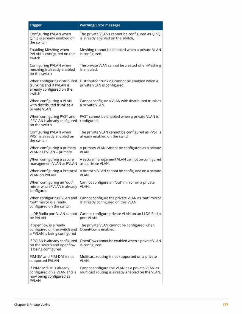
Warning/Error messageTrigger
The private VLANs cannot be configured as QinQis already enabled on the switch.
Configuring PVLAN whenQinQ is already enabled onthe switch
Meshing cannot be enabled when a private VLANis configured.
Enabling Meshing whenPVLAN is configured on theswitch
Theprivate VLAN cannot be createdwhenMeshingis enabled.
Configuring PVLAN whenmeshing is already enabledon the switch
Distributed trunking cannot be enabled when aprivate VLAN is configured.
When configuring distributedtrunking and if PVLAN isalready configured on theswitch
Cannot configure a VLANwith distributed trunk asa private VLAN.
When configuring a VLANwith distributed trunk as aprivate VLAN
PVST cannot be enabled when a private VLAN isconfigured.
When configuring PVST andif PVLAN is already configuredon the switch
The private VLAN cannot be configured as PVST isalready enabled on the switch.
Configuring PVLAN whenPVST is already enabled onthe switch
A primary VLAN cannot be configured as a privateVLAN.
When configuring a primaryVLAN as PVLAN – primary
A securemanagement VLAN cannot be configuredas a private VLAN.
When configuring a securemanagement VLANas PVLAN
Aprotocol VLAN cannot be configured on a privateVLAN.
When configuring a ProtocolVLAN on PVLAN
Cannot configure an “out” mirror on a privateVLAN.
When configuring an “out”mirrorwhenPVLAN is alreadyconfigured
Cannot configure the private VLAN as “out” mirroris already configured on this VLAN.
When configuring PVLANand“out” mirror is alreadyconfigured on the switch
Cannot configure private VLAN on an LLDP Radioport VLAN.
LLDPRadio port VLAN cannotbe PVLAN
The private VLAN cannot be configured whenOpenFlow is enabled.
If openflow is alreadyconfigured on the switch anda PVLAN is being configured
OpenFlow cannot be enabledwhen a private VLANis configured.
If PVLAN is already configuredon the switch and openflowis being configured
Mulitcast routing is not supported on a privateVLAN.
PIM-SM and PIM-DM is notsupported PVLAN
Cannot configure the VLAN as a private VLAN asmulticast routing is already enabled on the VLAN.
If PIM-SM/DM is alreadyconfigured on a VLAN and isnow being configured asPVLAN
Chapter 6 Private VLANs 177

Warning/Error messageTrigger
IGMP querier is not supported on a secondaryVLAN.
IGMP querier is notsupported on a secondaryVLAN
Cannot configure the VLAN as a private VLAN asIGMP querier is already configured on the VLAN.
IF IGMP querier is alreadyconfigured on the VLAN andis now being made as aPVLAN
IGMP Proxy is not supported on a private VLAN.IGMP-proxy is not supportedon PVLAN
Cannot configure the VLAN as a private VLAN asIGMP Proxy is already configured on the VLAN.
IF IGMP Proxy is alreadyconfigured on the VLAN andis now being made as aPVLAN
Isolate-list configuration is not supported on aprivate VLAN.
Isolate-list configuration isnot allowed on PVLAN
Cannot configure the VLAN as a private VLAN asIsolate-list is already configured on the VLAN.
If Isolate-list is configured onthe VLAN and is now beingmade as a PVLAN
Cannot configure the VLAN as a private VLAN asthis is a BYOD onboarding VLAN.
A BYOD onboarding VLANcannot be configured as aprivate VLAN.
Cannot configure the BYOD on a private VLAN.If a VLAN is a private VLAN,this VLAN cannot beconfigured as a BYODonboarding VLAN
Layer3 features cannot be disabled on a secondaryVLAN. It should be disabled on the primary VLAN
disable layer3 should beblocked on a secondary VLAN
andwill automatically apply to all secondary VLANsassociated with that primary VLAN.
Cannot block a port from becoming member onprivate VLAN.
Any port cannot be blockedfrom becoming a member ofthe private VLAN
L3-mac-address cannot be associated with asecondary VLAN. It should be associated to the
Association ofL3-MAC-address must beblocked on secondary VLAN. primary VLAN and will automatically apply to all
secondary VLANs associated with that primaryVLAN.
Cannot set a predefined protocol for the privateVLAN.
Setting a predefined protocolshould be blocked on privateVLAN.
VLAN based traffic prioritization cannot beconfigured on secondary VLAN. It should be
VLAN-based trafficprioritization (qos) should beblocked on secondary VLANs. configured on the primary VLAN and will
automatically apply to all secondary VLANsassociated with that primary VLAN.
QoS/Mirror policy cannot be configured onsecondary VLAN. It should be configured on the
QoS/Mirror policyconfiguration should beblocked on secondary VLANs. primary VLAN and will automatically apply to all
secondary VLANs associated with that primaryVLAN.
178 HPE ArubaOS-Switch Advanced Traffic Management Guide for WC.16.02
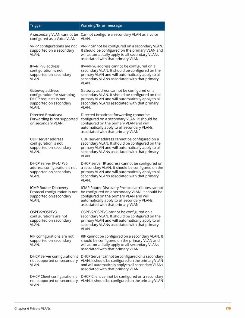
Warning/Error messageTrigger
Cannot configure a secondary VLAN as a voiceVLAN.
A secondary VLAN cannot beconfigured as a Voice VLAN.
VRRP cannot be configured on a secondary VLAN.It should be configured on the primary VLAN and
VRRP configurations are notsupported on a secondaryVLAN. will automatically apply to all secondary VLANs
associated with that primary VLAN.
IPv4/IPv6 address cannot be configured on asecondary VLAN. It should be configured on the
IPv4/IPv6 addressconfiguration is not
primary VLAN and will automatically apply to allsupported on secondaryVLAN. secondary VLANs associated with that primary
VLAN.
Gateway address cannot be configured on asecondary VLAN. It should be configured on the
Gateway addressconfiguration for stamping
primary VLAN and will automatically apply to allDHCP requests is notsecondary VLANs associated with that primaryVLAN.
supported on secondaryVLAN.
Directed broadcast forwarding cannot beconfigured on a secondary VLAN. It should be
Directed BroadcastForwarding is not supportedon secondary VLAN. configured on the primary VLAN and will
automatically apply to all secondary VLANsassociated with that primary VLAN.
UDP server address cannot be configured on asecondary VLAN. It should be configured on the
UDP server addressconfiguration is not
primary VLAN and will automatically apply to allsupported on secondaryVLAN. secondary VLANs associated with that primary
VLAN.
DHCP server IP address cannot be configured ona secondary VLAN. It should be configured on the
DHCP server IPv4/IPv6address configuration is not
primary VLAN and will automatically apply to allsupported on secondaryVLAN. secondary VLANs associated with that primary
VLAN.
ICMP Router Discovery Protocol attributes cannotbe configured on a secondary VLAN. It should be
ICMP Router DiscoveryProtocol configuration is not
configured on the primary VLAN and willsupported on secondaryVLAN. automatically apply to all secondary VLANs
associated with that primary VLAN.
OSPFv2/OSPFv3 cannot be configured on asecondary VLAN. It should be configured on the
OSPFv2/OSPFv3configurations are not
primary VLAN and will automatically apply to allsupported on secondaryVLAN. secondary VLANs associated with that primary
VLAN.
RIP cannot be configured on a secondary VLAN. Itshould be configured on the primary VLAN and
RIP configurations are notsupported on secondaryVLAN. will automatically apply to all secondary VLANs
associated with that primary VLAN.
DHCP Server cannot be configured on a secondaryVLAN. It should be configured on the primary VLAN
DHCP Server configuration isnot supported on secondaryVLAN. andwill automatically apply to all secondary VLANs
associated with that primary VLAN.
DHCP Client cannot be configured on a secondaryVLAN. It should be configured on the primary VLAN
DHCP Client configuration isnot supported on secondaryVLAN.
Chapter 6 Private VLANs 179

Warning/Error messageTrigger
andwill automatically apply to all secondary VLANsassociated with that primary VLAN.
Neighbor discovery options cannot be configuredon a secondary VLAN. It should be configured on
Neighbor Discoveryconfigurations are not
the primary VLAN and will automatically apply tosupported on secondaryVLAN. all secondary VLANs associated with that primary
VLAN.
ARP-Protect cannot be configured on a secondaryVLAN. It should be configured on the primary VLAN
ARP-Protect feature cannotbe enabled on secondaryVLAN. andwill automatically apply to all secondary VLANs
associated with that primary VLAN.
DHCP Snooping cannot be configured on asecondary VLAN. It should be configured on the
DHCP Snooping featurecannot be enabled onsecondary VLAN. primary VLAN and will automatically apply to all
secondary VLANs associated with that primaryVLAN.
Cannot configure secondary VLAN as thedestination VLAN for static route.
Static routes cannot beconfigured with secondaryVLAN as the destinationVLAN.
static IP binding in the DHCP binding databasecannot be configured for a secondary VLAN. It
Static IP binding cannot beconfigured on a secondaryVLAN. should be configured on the primary VLAN and
will automatically apply to all secondary VLANsassociated with that primary VLAN.
source-interface cannot be specified on asecondary VLAN. It should be specified on the
Source-interfaceconfiguration is not
primary VLAN and will automatically apply to allsupported on secondaryVLAN. secondary VLANs associated with that primary
VLAN.
source-route cannot be enabled on a secondaryVLAN. It should be enabled on the primary VLAN
Source-route cannot beenabled on secondary VLAN.
andwill automatically apply to all secondary VLANsassociated with that primary VLAN.
Cannot configure private VLAN as interfacebetween DT peers.
Private VLAN cannot beconfigured as interfacebetween DT peers.
Cannot configure private VLAN as a ManagementVLAN.
Private VLAN cannot beconfigured as ManagementVLAN.
Cannot enable primary VLAN feature on privateVLAN.
Primary VLAN feature cannotbe enabled on private VLANs.
Cannot specify secondary VLAN as the SourceVLAN for Ping.
Source VLAN for ping cannotbe secondary VLAN.
Cannot configure secondary VLANs as smart-linkprotected-vlans.
Secondary VLANs cannot beconfigured as smart-linkprotected VLANs.
Cannot specify secondary VLAN to configure RPVSTparameters.
Spanning tree attributescannot be configured onsecondary VLAN.
180 HPE ArubaOS-Switch Advanced Traffic Management Guide for WC.16.02

Warning/Error messageTrigger
Cannot specify secondary VLAN as the SourceVLAN for traceroute.
Source VLAN for traceroutecannot be secondary VLAN.
Static-mac cannot be bind to multiple VLANs in asingle PVLAN instance.
A mac can only belocked-down to a singleVLAN. An error needs to bethrown when a static-mac isbeing locked-down multipleVLANs of the same PVLANinstance.• Static-mac 023456-122121
vlan 100 int 2• Static-mac 023456-122121
vlan 101 int 2• Static-mac 023456-122121
vlan 101 int 3Cannot be bound to multipleVLANs in a single PVLANinstance
Cannot configure port as forbid on a private VLAN.When configuring a port on aVLAN as forbid port
Cannot configure the VLAN as primary VLAN asforbiddenports are alreadymembers of this VLAN.
When configuring a VLANwith forbidden ports asprimary VLAN
Cannot clear the PVLAN induced MAC address.Clearing the learnt macaddress
Proxy ARP cannot be enabled when the privateVLAN is configured.
When trying to enable/disableproxy ARP on secondaryVLAN
Local proxy ARP cannot be enabled when theprivate VLAN is configured.
When trying to enable/disablelocal proxy ARP on secondaryVLAN
VLAN <VLAN_ID> cannot be a secondary(isolated/community) VLAN as DHCP snooping isenabled on this VLAN.
When configuring VLAN onwhich DHCP snooping isenabled as secondary VLAN
VLAN <VLAN_ID> cannot be a secondary(isolated/community) VLAN as DHCPv6 snoopingis enabled on this VLAN.
When configuring VLAN onwhich DHCPv6 snooping isenabled as secondary VLAN
VLAN <VLAN_ID> cannot be a secondary(isolated/community) VLAN as IPv4 static bindingsare present on this VLAN.
When configuring VLAN onwhich IPv4 static bindings arepresent as secondary VLAN
VLAN <VLAN_ID> cannot be a secondary(isolated/community) VLAN as IPv6 static bindingsare present on this VLAN.
When configuring VLAN onwhich IPv6 static bindings arepresent as secondary VLAN
VLAN <VLAN_ID> cannot be a secondary(isolated/community) VLAN as arp-protect isenabled on this VLAN.
When configuring VLAN onwhich ARP protect is enabledas secondary VLAN
Cannot configure the VLANs as a primary VLAN asthis is a BYOD onboarding VLAN.
When trying to configuringBYOD onboarding VLAN asprimary VLAN
Chapter 6 Private VLANs 181

Warning/Error messageTrigger
Cannot configure private vlan as more than oneMAC lockdown entries are present in this privatevlan.
When configuring a VLAN onwhichmultipleMAC lockdownentries present for a VLAN asprivate VLAN
Port <PORT_NUM> cannot be untrusted becauseit is a member of the primary VLAN.
When configuring a primaryVLAN port as untrusted port
Error messages
Error messagesTrigger
Cannot change the private VLAN type. Change the VLAN to a non-privateVLAN and then configure the private VLAN type.
A primary VLANcannot bemadeas a secondaryVLAN and vice-versa.
The primary VLAN cannot be deleted because it has secondary VLANsassociated. Delete the association before deleting the primary VLAN.
The primary VLAN cannot be deleted if it isassociated with secondary VLANs.
Cannot configure the primary VLANbecause the number of primary VLANsexceeds the maximum limit of 16.
If the number of primary VLANs configured hasreached the limit on the system (16).
Cannot create more than 8 community VLANs under a primary VLAN.If the number of community VLANs configuredfor under a primary VLANhas reached the limiton the system (8).
Cannot configure the promiscuous ports as the VLAN is not a primaryVLAN.
Configuringof promiscuousportwill be allowedonly if the private VLAN is of type primary.
Cannot configure the DEFAULT VLAN as a primary VLAN.Default VLAN cannot be a private VLAN.
The private-vlan configuration is not allowed under this VLAN as this VLANis already associated with another primary VLAN.
On a secondary VLAN configuringprimary/isolated/community/promiscuousportshould not be allowed.
Cannot associate an already existing VLANs as secondary to the primaryVLAN.
When associating an already existing VLAN asa secondary VLAN to a primary VLAN.
VLAN <Number> is not a private VLAN.If the VLAN is not a private VLAN.
IGMP V3 is not supported with PVLAN.
MTM Lookup Mode IP is not supported with PVLAN.
182 HPE ArubaOS-Switch Advanced Traffic Management Guide for WC.16.02
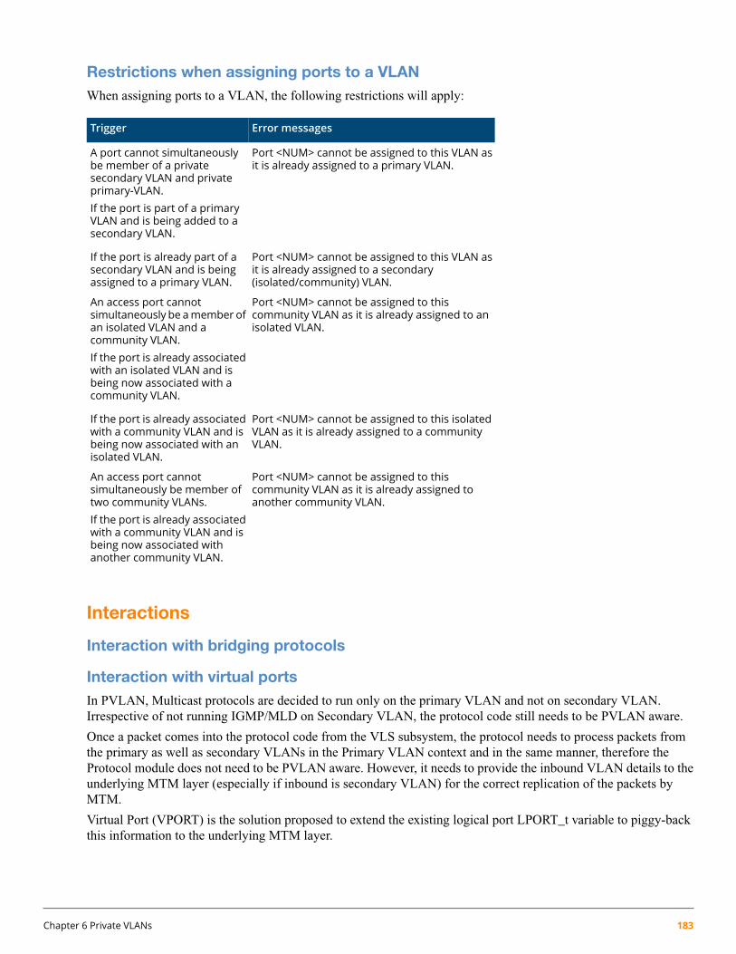
Restrictions when assigning ports to a VLANWhen assigning ports to a VLAN, the following restrictions will apply:
Error messagesTrigger
Port <NUM> cannot be assigned to this VLAN asit is already assigned to a primary VLAN.
A port cannot simultaneouslybe member of a privatesecondary VLAN and privateprimary-VLAN.If the port is part of a primaryVLAN and is being added to asecondary VLAN.
Port <NUM> cannot be assigned to this VLAN asit is already assigned to a secondary(isolated/community) VLAN.
If the port is already part of asecondary VLAN and is beingassigned to a primary VLAN.
Port <NUM> cannot be assigned to thiscommunity VLAN as it is already assigned to anisolated VLAN.
An access port cannotsimultaneously be amember ofan isolated VLAN and acommunity VLAN.If the port is already associatedwith an isolated VLAN and isbeing now associated with acommunity VLAN.
Port <NUM> cannot be assigned to this isolatedVLAN as it is already assigned to a communityVLAN.
If the port is already associatedwith a community VLAN and isbeing now associated with anisolated VLAN.
Port <NUM> cannot be assigned to thiscommunity VLAN as it is already assigned toanother community VLAN.
An access port cannotsimultaneously be member oftwo community VLANs.If the port is already associatedwith a community VLAN and isbeing now associated withanother community VLAN.
Interactions
Interaction with bridging protocols
Interaction with virtual portsIn PVLAN, Multicast protocols are decided to run only on the primary VLAN and not on secondary VLAN.Irrespective of not running IGMP/MLD on Secondary VLAN, the protocol code still needs to be PVLAN aware.
Once a packet comes into the protocol code from the VLS subsystem, the protocol needs to process packets fromthe primary as well as secondary VLANs in the Primary VLAN context and in the same manner, therefore theProtocol module does not need to be PVLAN aware. However, it needs to provide the inbound VLAN details to theunderlying MTM layer (especially if inbound is secondary VLAN) for the correct replication of the packets byMTM.
Virtual Port (VPORT) is the solution proposed to extend the existing logical port LPORT_t variable to piggy-backthis information to the underlying MTM layer.
Chapter 6 Private VLANs 183

Security interactions with Private VLANs
dhcp-snooping trust
Syntax
dhcp-snooping trust interface-list
Description
Configure interfaces as trusted ports. Alternatively this command can be invoked in an interface context.
Primary VLAN ports are automatically configured trusted ports. This behavior also applies to dhcpv6-snoopingand nd-snooping trust.
Dynamic IP lockdown
Impacted commands to enable Dynamic IP Lockdown feature on Private VLANs
show ip source-lockdown status
Syntax
show ip source-lockdown status
Description
Displays port State as active even if the port is associated with a Secondary VLAN, and DHCP Snooping is enabledon the corresponding Primary VLAN.
show ip source-lockdown bindings
Syntax
show ip source-lockdown bindings
Description
Displays the binding entries created by DIPLD and VLAN field displays the original VLAN.
show ip source-lockdown bindings [ethernet] <port>
Syntax
show ip source-lockdown bindings ethernet port
Description
Displays the binding entries created by DIPLD and “VLAN” field displays the original VLAN.
Dynamic ARP protection
arp protect vlan
Syntax
arp protect vlan vlan range
Description
ARP protect can be configured only on Primary VLANs.
184 HPE ArubaOS-Switch Advanced Traffic Management Guide for WC.16.02
IP source binding
Syntax
ip source binding mac-address vlan vlan-id ip-address interface port-number
Description
VLAN field should take only Primary VLAN Ids.
Show arp-protect
Syntax
show arp-protect
Description
Displays Primary VLAN information while showing Protected VLANs.
Multicast hardware filterMulticast Hardware Filter consumption can increase with PVLAN because of Filter Replication across secondaryVLANs. As a result of this, Filters can get exhausted at a much faster rate than compared to Non-PVLANs. TheMulticast Application goes into an Error State when the System runs out of filter and starts Flooding Data. Thefollowing two commands are used to take it out of error state:
• igmp reload
• mld reload
Interaction with multicast protocols(IGMP/MLD)
• PVLAN is only supported for IGMP/MLD.
• PVLAN is not supported for L3 protocols like PIM-DM and PIM-SM.
• Both IGMP and MLD support PVLAN rules of traffic isolation.
• IGMP/MLD cannot be configured on secondary VLANs.
• Query packets received on secondary VLAN ports shall be dropped.
• IGMP V3 is currently not supported with Private VLANs.
MTM test mode/debugMTM Test mode commands are Secondary VLAN aware and can be used to debug/isolate any secondary VLANrelated issues. The following Test mode commands can give important information on secondary VLANs withrespect to Filter Consumption and Replication.
• Mtmfiltershow
• Mtmvlanshow
Chapter 6 Private VLANs 185
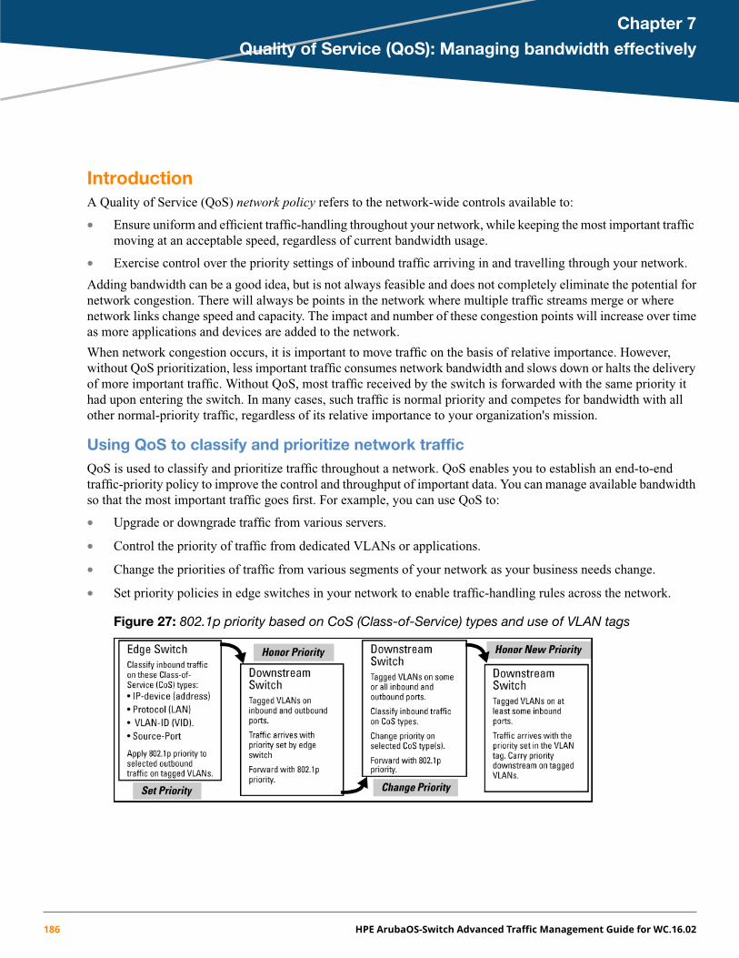
Chapter 7
Quality of Service (QoS): Managing bandwidth effectively
IntroductionA Quality of Service (QoS) network policy refers to the network-wide controls available to:
• Ensure uniform and efficient traffic-handling throughout your network, while keeping the most important trafficmoving at an acceptable speed, regardless of current bandwidth usage.
• Exercise control over the priority settings of inbound traffic arriving in and travelling through your network.
Adding bandwidth can be a good idea, but is not always feasible and does not completely eliminate the potential fornetwork congestion. There will always be points in the network where multiple traffic streams merge or wherenetwork links change speed and capacity. The impact and number of these congestion points will increase over timeas more applications and devices are added to the network.
When network congestion occurs, it is important to move traffic on the basis of relative importance. However,without QoS prioritization, less important traffic consumes network bandwidth and slows down or halts the deliveryof more important traffic. Without QoS, most traffic received by the switch is forwarded with the same priority ithad upon entering the switch. In many cases, such traffic is normal priority and competes for bandwidth with allother normal-priority traffic, regardless of its relative importance to your organization's mission.
Using QoS to classify and prioritize network trafficQoS is used to classify and prioritize traffic throughout a network. QoS enables you to establish an end-to-endtraffic-priority policy to improve the control and throughput of important data. You can manage available bandwidthso that the most important traffic goes first. For example, you can use QoS to:
• Upgrade or downgrade traffic from various servers.
• Control the priority of traffic from dedicated VLANs or applications.
• Change the priorities of traffic from various segments of your network as your business needs change.
• Set priority policies in edge switches in your network to enable traffic-handling rules across the network.
Figure 27: 802.1p priority based on CoS (Class-of-Service) types and use of VLAN tags
186 HPE ArubaOS-Switch Advanced Traffic Management Guide for WC.16.02

Figure 28: Application of Differentiated Services Codepoint (DSCP) policies
Applying QoS to inbound traffic at the network edge
At the edge switch, QoS classifies certain traffic types and in some cases applies a DSCP policy. At the next hop(downstream switch) QoS honors the policies established at the edge switch. Further downstream, another switchmay reclassify some traffic by applying new policies, and yet other downstream switches can be configured to honorthe new policies.
Preserving QoS in outbound traffic in a VLAN
QoS is implemented in the form of rules or policies that are configured on the switch. Although you can use QoSto prioritize traffic only while it moves through the switch, you derive the maximum benefit by using QoS in an802.1Q VLAN environment (with 802.1p priority tags) or in an untagged VLAN environment (with DSCP policiesin which QoS sets priorities that downstream devices can support without reclassifying the traffic).
Using QoS to optimize existing network resources
By prioritizing traffic, QoS supports traffic growth on the network while optimizing the use of existing resources—anddelaying the need for further investments in equipment and services. QoS enables you to:
• Specify which traffic has higher or lower priority, regardless of current network bandwidth, or the relativepriority setting of the traffic when it is received on the switch.
• Change (upgrade or downgrade) the priority of outbound traffic.
• Override "illegal" packet priorities set by upstream devices or applications that use 802.1Q VLAN tagging with802.1p priority tags.
Classifier-based traffic marking
QoS on the switches covered in this guide support these types of traffic marking:
• 802.1p prioritization: Controls the outbound port queue priority for traffic leaving the switch, and (if trafficexits through a VLAN-tagged port) sends the priority setting in packet headers to downstream devices.
• IP Type-of-Service (ToS): Enables the switch to set, change, and honor prioritization policies by using theDifferentiated Services (diffserv) bits in the ToS byte of IPv4 packet headers.
Enabling and disabling TCP push preserve
Use the following tcp-push-preserve commands to enable or disable TCP push preserve in the switch.
Syntax:
[no] tcp-push-preserveshow tcp-push-preserve
Chapter 7 Quality of Service (QoS): Managing bandwidth effectively 187
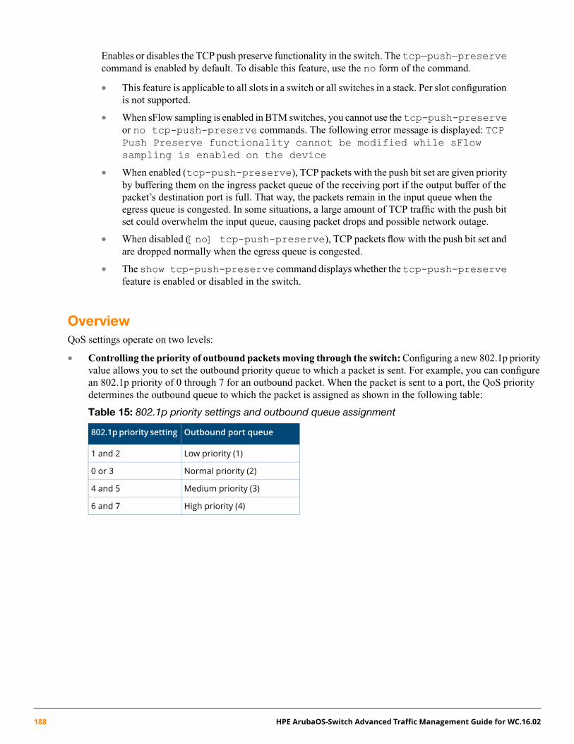
Enables or disables the TCP push preserve functionality in the switch. The tcp—push—preservecommand is enabled by default. To disable this feature, use the no form of the command.
• This feature is applicable to all slots in a switch or all switches in a stack. Per slot configurationis not supported.
• When sFlow sampling is enabled in BTM switches, you cannot use thetcp-push-preserveor no tcp-push-preserve commands. The following error message is displayed: TCPPush Preserve functionality cannot be modified while sFlowsampling is enabled on the device
• When enabled (tcp-push-preserve), TCP packets with the push bit set are given priorityby buffering them on the ingress packet queue of the receiving port if the output buffer of thepacket’s destination port is full. That way, the packets remain in the input queue when theegress queue is congested. In some situations, a large amount of TCP traffic with the push bitset could overwhelm the input queue, causing packet drops and possible network outage.
• When disabled ([no] tcp-push-preserve), TCP packets flow with the push bit set andare dropped normally when the egress queue is congested.
• Theshow tcp-push-preserve command displays whether thetcp-push-preservefeature is enabled or disabled in the switch.
OverviewQoS settings operate on two levels:
• Controlling the priority of outbound packets moving through the switch: Configuring a new 802.1p priorityvalue allows you to set the outbound priority queue to which a packet is sent. For example, you can configurean 802.1p priority of 0 through 7 for an outbound packet. When the packet is sent to a port, the QoS prioritydetermines the outbound queue to which the packet is assigned as shown in the following table:
Table 15: 802.1p priority settings and outbound queue assignment
Outbound port queue802.1ppriority setting
Low priority (1)1 and 2
Normal priority (2)0 or 3
Medium priority (3)4 and 5
High priority (4)6 and 7
188 HPE ArubaOS-Switch Advanced Traffic Management Guide for WC.16.02

(In an 802.1Q VLAN environment with VLAN-tagged ports, if QoS is not configured on the switch, but isconfigured on an upstream device, the priorities carried in the packets determine the forwarding queues in theswitch.)
• Configuring a priority for outbound packets and a service (priority) policy for use by downstream devices:
◦ DSCP Policy: This feature enables you to set a priority policy in outbound IP packets. (You can configuredownstream devices to read and use this policy.) This method is not dependent on VLAN-tagged ports tocarry priority policy to downstream devices, and can:
— Change the codepoint (the upper 6 bits) in the ToS byte.
— Set a new 802.1p priority for the packet.
(Setting DSCP policies requires IPv4 inbound packets.)
◦ 802.1p priority rules: An outbound, VLAN-tagged packet carries an 802.1p priority setting that wasconfigured (or preserved) in the switch. This priority setting ranges from 0 to 7, and can be used bydownstream devices having up to eight outbound port queues. Thus, if packets within the switch move atthe four priority levels shown in Table 15 (page 188), they still can carry an 802.1p priority that can beused by downstream devices having more or less than the four priority levels in the switches covered inthis guide. Also, if the packet enters the switch with an 802.1p priority setting, QoS can override thissetting if configured with an 802.1p priority rule to do so.
If your network uses only one VLAN (and therefore does not require VLAN-tagged ports), you can stillpreserve 802.1p priority settings in your traffic by configuring the ports as tagged VLAN memberson the links between devices you want to honor traffic priorities.
Rule and policy limits: The switches covered in this guide allow up to 400 802.1p priority rules and/orDSCP policies in any combination.
You can configure a QoS priority of 0 through 7 for an outbound packet. When the packet is then sent to a port, theQoS priority determines which outbound queue the packet uses:
Table 16: QoS priority settings and operation
Outbound portqueue
QoS prioritysettings
Low priority1, 2
Normal priority0, 3
Medium priority4, 5
High priority6, 7
If a packet is not in a VLAN-tagged port environment, then the QoS settings in Table 16 control only to whichoutbound queue the packet goes. Without VLAN tagging, no 802.1p priority is added to the packet for downstreamdevice use. But if the packet is in a VLAN-tagged environment, then the above setting is also added to the packetas an 802.1p priority for use by downstream devices and applications (shown in Table 17). In either case, an IPpacket can also carry a priority policy to downstream devices by using DSCP-marking in the ToS byte.
Chapter 7 Quality of Service (QoS): Managing bandwidth effectively 189

Table 17: Mapping switch QoS priority settings to device queues
Queue assignment in downstream deviceswith:
802.1p prioritysetting added totagged VLANOutbound port
queues in theswitch
Prioritysetting 2 queues3 queues8 queues
packets exiting theswitch
Queue 1
Queue 1Queue 11 (low priority)
Queue 11
Queue 222
Queue 2Queue 30 (normal priority)
Queue 20
Queue 433
Queue 2Queue 3
Queue 54 (medium priority)Queue 3
4
Queue 655
Queue 76 (high priority)Queue 4
6
Queue 877
The QoS queue configuration feature can change the number of outbound port queues in the switch fromfour (the default) to eight queues or twoqueues. Formore information, see “QoSqueue configuration” (page 225).
Classifiers for prioritizing outbound packets
Regarding using multiple criteria: Hewlett Packard Enterprise recommends that you configure a minimumnumber of the available QoS classifiers for prioritizing any given packet type. Increasing the number of activeclassifier options for a packet type increases the complexity of the possible outcomes and consumes switchresources.
Packet classifiers and evaluation order
The switches covered in this guide provide six QoS classifiers (packet criteria) you can use to configure QoS priority.
Table 18: Classifier search order and precedence
Global QoS classifierPrecedenceSearch order
UDP/TCP application type (port)1 (highest)1
Device priority (destination or source IP address)22
IP type of service (ToS): precedence and DSCP bit sets (IP packetsonly)
33
IP protocol (IP, IPX, ARP, AppleTalk, SNA, and NetBeui)44
VLAN ID55
Incoming source-port on the switch66
The incoming 802.1p priority (present in tagged VLANenvironments) is preserved if no global QoS classifier with ahigher precedence matches.
7 (lowest)Default
190 HPE ArubaOS-Switch Advanced Traffic Management Guide for WC.16.02
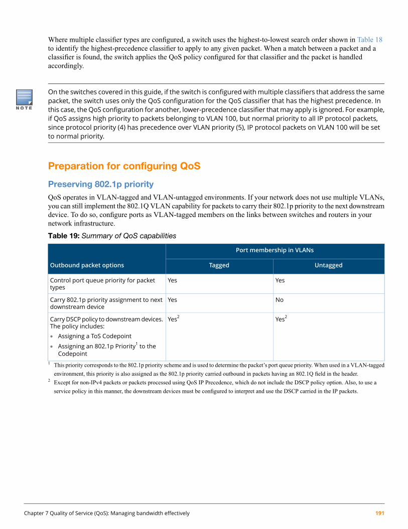
Where multiple classifier types are configured, a switch uses the highest-to-lowest search order shown in Table 18to identify the highest-precedence classifier to apply to any given packet. When a match between a packet and aclassifier is found, the switch applies the QoS policy configured for that classifier and the packet is handledaccordingly.
On the switches covered in this guide, if the switch is configured withmultiple classifiers that address the samepacket, the switch uses only the QoS configuration for the QoS classifier that has the highest precedence. Inthis case, theQoS configuration for another, lower-precedence classifier thatmay apply is ignored. For example,if QoS assigns high priority to packets belonging to VLAN 100, but normal priority to all IP protocol packets,since protocol priority (4) has precedence over VLAN priority (5), IP protocol packets on VLAN 100 will be setto normal priority.
Preparation for configuring QoS
Preserving 802.1p priorityQoS operates in VLAN-tagged and VLAN-untagged environments. If your network does not use multiple VLANs,you can still implement the 802.1Q VLAN capability for packets to carry their 802.1p priority to the next downstreamdevice. To do so, configure ports as VLAN-tagged members on the links between switches and routers in yournetwork infrastructure.
Table 19: Summary of QoS capabilities
Port membership in VLANs
Outbound packet options UntaggedTagged
YesYesControl port queue priority for packettypes
NoYesCarry 802.1p priority assignment to nextdownstream device
Yes2Yes2CarryDSCPpolicy to downstreamdevices.The policy includes:• Assigning a ToS Codepoint
• Assigning an 802.1p Priority1 to theCodepoint
1 This priority corresponds to the 802.1p priority scheme and is used to determine the packet’s port queue priority. When used in a VLAN-tagged
environment, this priority is also assigned as the 802.1p priority carried outbound in packets having an 802.1Q field in the header.2 Except for non-IPv4 packets or packets processed using QoS IP Precedence, which do not include the DSCP policy option. Also, to use a
service policy in this manner, the downstream devices must be configured to interpret and use the DSCP carried in the IP packets.
Chapter 7 Quality of Service (QoS): Managing bandwidth effectively 191

Steps for configuring QoS on the switch1. Determine the QoS policy you want to implement. This includes analyzing the types of traffic flowing through
your network and identifying one or more traffic types to prioritize. In order of QoS precedence, these are:a. UDP/TCP applicationsb. Device Priority—destination or source IP address (Note that destination has precedence over source. See
Table 20.)c. IP ToS Precedence Bits (Leftmost three bits in the ToS field of IP packets)d. IP ToS Differentiated Service bits (Leftmost 6 bits in the ToS field of IP packets)e. Layer 3 Protocol Priorityf. VLAN Priority (requires at least one tagged VLAN on the network)g. Source-Porth. Incoming 802.1p Priority (requires at least one tagged VLAN on the network). In a tagged VLAN
environment, the incoming 802.1p priority is used as the default QoS classifier if no QoS classifier witha higher precedence matches
2. Select the QoS option you want to use. Table 20 lists the traffic types (QoS classifiers) and the QoS optionsyou can use for prioritizing or setting a policy on these traffic types:
Table 20: QoS marking supported by QoS classifiers
Type of QoS marking used to prioritize outbound traffic
Global QoS classifiersDSCP policy2: DSCP codepoint with
802.1p priority802.1p Priority1 only
SupportedSupportedUDP/TCP
SupportedSupportedIP Device
Not SupportedSupported3IP Precedence
SupportedSupportedIP DiffServ
Not SupportedSupportedL3 Protocol
SupportedSupportedVLAN ID
SupportedSupportedSource Port1 When you configure only the 802.1p priority to mark packets that match a global QoS classifier, the selected traffic is prioritized and
sent to the corresponding outbound port queue on the switch. VLAN-tagged ports are necessary to carry the 802.1p priority in a packet
header to downstream devices.2 When you configure a DSCP policy to mark packets that match a global QoS classifier, the selected traffic is also prioritized according
to the associated 802.1p priority and sent to the corresponding outbound port queue on the switch. VLAN-tagged ports carry the 802.1p
priority in a packet header to downstream devices. In addition, you can configure downstream devices to read the DSCP value in IP
packets and implement the service policy implied by the codepoint.3 When using a global QoS IP Precedence classifier, the 802.1p priority is automatically assigned to matching packets based on the IP
precedence bit set in the packet header.
3. If you want 802.1p priority settings to be included in outbound packets, ensure that tagged VLANs are configuredon the appropriate downstream links.
4. Determine the actual QoS configuration changes you will need to make on each QoS-capable device in yournetwork in order to implement the desired policy. Also, if you want downstream devices to read and use DSCPsin IP packets from the switch, configure them to do so by enabling ToS Differentiated Service mode and makingsure that the same DSCP policies are configured.
192 HPE ArubaOS-Switch Advanced Traffic Management Guide for WC.16.02

Demonstrating how the switch uses resources in DSCP configurations
If ToS Diff-Services mode is enabled, then thirteen rules are immediately used for these codepoints. Adding a newDSCP policy (for example, 001111 with a “5” priority) and then configuring ToS Diff-Services to assign inboundpackets with a codepoint of 001010 to the 001111 policy implements all policies configured in the DSCP map and,in this case, uses 13 rules—one for each codepoint invoked in the switch’s current DSCP configuration (the 13default codepoints). Adding another Diff-Services assignment, such as assigning inbound packets with a codepointof 000111 to the Expedited Forwarding policy (101110), would use one more rule on all ports.
Using classifiers to configure QoS for outbound traffic
In addition to the information in this section on the various QoS classifiers, see “QoS operating notes andrestrictions” (page 228).
Viewing the QoS configurationExamples of the show qos output are included with the example for each priority type.
Syntax:
show qos <priority-classifier>device-priority: Displays the device priority table/configuration (priority based on the IPaddress).
dscp-map: Displays mappings between DSCP policy and 802.1p priority.
port-priority: Displays the current source-port priority configuration.
protocol-priority: Displays the protocol priority configuration.
queue-config: Displays the outbound port queue configuration information.
resources: Displays the resources used by the Policy Enforcement Engine.
tcp-udp-port-priority: Displays the TCP/UDP port priorities.
type-of-service: Displays the current type-of-service priority configuration. The displayoutput differs according to the ToS option used:
• IP Precedence
• Diffserve
vlan-priority: Displays the current VLAN priority configuration.
No overrideBy default, the show command outputs automatically list No-override for priority options that have not beenconfigured. This means that if you do not configure a priority for a specific option, QoS does not prioritize packetsto which that option applies, resulting in the No-override state.
• IP packets received through a VLAN-tagged port are managed using the 802.1p priority they carry in the 802.1Qfield in their headers.
• VLAN-tagged packets received through an untagged port are handled by the switch with “normal” priority.
the show qos vlan-priority output shows the global QoS configurations on the switch that are configuredwith the VLAN ID classifier. Note that non-default 802.1p priorities have been configured for VLAN IDs 22 and33; packets received on VLAN 1 are managed with the default settings, as described in the two bulleted items above.
Chapter 7 Quality of Service (QoS): Managing bandwidth effectively 193

Figure 29: Output for the show qos vlan-priority command (example)
Global TCP/UDP classifier
Global QoS classifier precedence: 1
When you use TCP or UDP and a layer 4 Application port number as a global QoS classifier, traffic carrying thespecified TCP/UDP port numbers is marked with a specified priority level, without regard for any other QoS classifiersin the switch.
TCP/UDP QoS applications are supported for IPv4 packets only.
Options for assigning priority
Priority control options for TCP or UDP packets carrying a specified TCP or UDP port number include:
• 802.1p priority
• DSCP policy (Assigning a new DSCP and an associated 802.1p priority; inbound packets must be IPv4.)
For a given TCP or UDP port number, you can use only one of the above options at a time. However, for differentport numbers, you can use different options.
You can have up to 30 rules maximum for all TCP or UDP ports with assigned priorities.
TCP/UDP port number ranges
There are three ranges:
• Well-Known Ports: 0 – 1023
• Registered Ports: 1024 – 49151
• Dynamic and Private Ports: 49152 – 65535
For more information, including a listing of UDP/TCP port numbers, go to the Internet Assigned Numbers Authority(IANA) website at:
http://www.iana.org
Then click:
Protocol Number Assignment Services
P (under Directory of General Assigned Numbers)
Port Numbers
Assigning an 802.1p priority for a global TCP/UDP classifier
This option assigns an 802.1p priority to (IPv4) TCP or UDP packets as described below.
194 HPE ArubaOS-Switch Advanced Traffic Management Guide for WC.16.02

Syntax:
qos < udp-port | tcp-port > < tcp or udp port-number | range <start end> >priority < 0-7>
Configures an 802.1p priority for outbound packets having the specified TCP or UDP applicationport number. This priority determines the packet’s queue in the outbound port to which it is sent.If the packet leaves the switch on a tagged port, it carries the 802.1p priority with it to the nextdownstream device. (Default: Disabled)port-number: TCP/UDP port number from 1 to 65535.
range <start end>: Marks a range of TCP/UDP ports. If you specify a range, the minimumport number must precede the maximum port number in the range.
priority <0-7>: Marks the specified 802.1p priority in matching TCP or UDP packets.
Syntax:
no qos < udp-port | tcp-port > < tcp-udp port-number | range <start end> >Deletes the specified UDP or TCP port number or range of numbers as QoS classifiers. See“Operating notes on using TCP/UDP port ranges” (page 195).
Syntax:
show qos tcp-udp-port-priorityDisplays a listing of all TCP and UDP QoS classifiers currently in the running-config file.
Operating notes on using TCP/UDP port ranges
• Only six concurrent policies are possible when using unique ranges. The number of policies allowed is less ifACLs are also using port ranges.
• No ranges allowed that include any port numbers configured as part of another QoS application port numberpolicy.
• An error message is generated if there are not enough hardware resources available when configuring a policy.
• The entire range of configured port numbers must be specified when using the no form of the command, forexample:
switch(config)#: qos udp-port range 1300 1399 dscp 001110
switch(config)#: no qos range 1300 1399
The following example displays the following configuration for TCP and UDP port prioritization:
Chapter 7 Quality of Service (QoS): Managing bandwidth effectively 195

Example 100: Configuration for TCP and UDP port prioritization
802.1p priority forUDP
802.1p priority forTCP
TCP/UDP port
77TCP Port 23 (Telnet)
77UDP Port 23 (Telnet)
22TCP Port 80 (World Wide Web HTTP)
11UDP Port 80 (World Wide Web HTTP)
Figure 30: Configuring 802.1p priority assignments on TCP/UDP ports
Assigning a DSCP policy for a global TCP/UDP classifier
This option assigns a previously configured DSCP policy (codepoint and 802.1p priority) to (IPv4) TCP or UDPpackets having the specified port number. The switch does the following:
1. Selects an incoming IP packet if the TCP or UDP port number it carries matches the port number specified inthe TCP or UDP classifier (as shown in Figure 30, above).
2. Overwrites (re-marks) the packet's DSCP with the new DSCP configured for matching packets.3. Assigns the 802.1p priority associated with the new DSCP (see “Differentiated Services Codepoint (DSCP)
mapping” (page 217)).4. Forwards the packet through the appropriate outbound port queue.
Creating a DSCP policy based on TCP/UDP port number classifiers
The following procedure creates a DSCP policy for IP packets carrying the selected TCP or UDP port-numberclassifier.
1. Identify the TCP or UDP port-number classifier you want to use for assigning a DSCP policy.2. Determine the DSCP policy for packets carrying the selected TCP or UDP port number or range of port numbers.
196 HPE ArubaOS-Switch Advanced Traffic Management Guide for WC.16.02
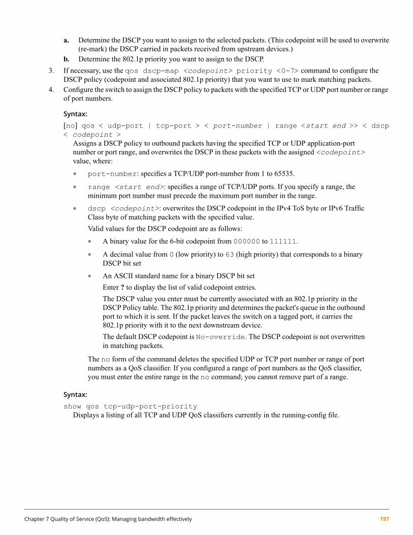
a. Determine the DSCP you want to assign to the selected packets. (This codepoint will be used to overwrite(re-mark) the DSCP carried in packets received from upstream devices.)
b. Determine the 802.1p priority you want to assign to the DSCP.
3. If necessary, use the qos dscp-map <codepoint> priority <0-7> command to configure theDSCP policy (codepoint and associated 802.1p priority) that you want to use to mark matching packets.
4. Configure the switch to assign the DSCP policy to packets with the specified TCP or UDP port number or rangeof port numbers.
Syntax:
[no] qos < udp-port | tcp-port > < port-number | range <start end >> < dscp< codepoint >
Assigns a DSCP policy to outbound packets having the specified TCP or UDP application-portnumber or port range, and overwrites the DSCP in these packets with the assigned <codepoint>value, where:
• port-number: specifies a TCP/UDP port-number from 1 to 65535.
• range <start end>: specifies a range of TCP/UDP ports. If you specify a range, theminimum port number must precede the maximum port number in the range.
• dscp <codepoint>: overwrites the DSCP codepoint in the IPv4 ToS byte or IPv6 TrafficClass byte of matching packets with the specified value.
Valid values for the DSCP codepoint are as follows:
• A binary value for the 6-bit codepoint from 000000 to 111111.
• A decimal value from 0 (low priority) to 63 (high priority) that corresponds to a binaryDSCP bit set
• An ASCII standard name for a binary DSCP bit set
Enter ? to display the list of valid codepoint entries.
The DSCP value you enter must be currently associated with an 802.1p priority in theDSCP Policy table. The 802.1p priority and determines the packet's queue in the outboundport to which it is sent. If the packet leaves the switch on a tagged port, it carries the802.1p priority with it to the next downstream device.
The default DSCP codepoint is No-override. The DSCP codepoint is not overwrittenin matching packets.
The no form of the command deletes the specified UDP or TCP port number or range of portnumbers as a QoS classifier. If you configured a range of port numbers as the QoS classifier,you must enter the entire range in the no command; you cannot remove part of a range.
Syntax:
show qos tcp-udp-port-priorityDisplays a listing of all TCP and UDP QoS classifiers currently in the running-config file.
Chapter 7 Quality of Service (QoS): Managing bandwidth effectively 197

Example:
This example shows how to assign the following DSCP policies to packets that match the specified TCP and UDPport applications:
DSCP PoliciesPort Applications
PriorityDSCP
700011123-UDP
500010180-TCP
1000010914-TCP
10000101001-UDP
1. Determine if the DSCP codepoints that you want to use to mark matching packets already have an 802.1ppriority assigned, which could indicate use by existing applications (show qos dscp-map command).
A DSCP codepoint must also have a priority configured before you can use it to mark matching packets.
switch(config)# show qos dscp-map
DSCP -> 802.p priority mappings
NOTE: ‘qos type-of-service diff-services’ must be configuredbefore DSCP is honored on inbound traffic.
DSCP CodePoint DSCP Value 802.1p tag DSCP Policy name-------------- ---------- ----------- ----------------------000000 0 0 cs0000001 1 No-override000010 2 No-override000011 3 No-override000100 4 No-override000101 5 No-override000110 6 No-override000111 7 No-override001000 8 1 cs1001001 9 No-override
2. Configure the DSCP policies for the codepoints you want to use.
switch(config)# qos dscp-map af11 priority 3switch(config)# qos dscp-map 13 priority 3switch(config)# qos dscp-map af13 priority 3switch(config)# write memory
switch(config)# show configswitch configuration:
; J9146 Configuration Editor; Created on release XX.15.XX
hostname “Switch”time daylight-time-rule Noneqos dscp-map af11 priority 3qos dscp-map 13 priority 3qos dscp-map af13 priority 3...
198 HPE ArubaOS-Switch Advanced Traffic Management Guide for WC.16.02

3. Assign the DSCP policies to the selected TCP/UDP port applications and display the result.
switch(config)# qos udp-port 23 dscp 000111switch(config)# qos tcp-port 80 dscp 000101switch(config)# qos tcp-port 914 dscp 000010switch(config)# qos udp-port range 1001 2000 dscp 000010
TCP/UDP port based priorities
| IP Packet Application |Protocol | Type Port Apply rule | DSCP Priority-------- + --------- ----------- ---------- + ------ -----------UDP | IPV4 23 DSCP | 8 7TCP | IPV4 80 DSCP | 6 5TCP | IPV4 914 DSCP | 3 1UDP | IPV4 1001-2000 DSCP | 3 1
The switch applies the DSCP policies in the about output to IP packets with the specified TCP/UDP portapplications that are received in the switch. The switch manages the packets as follows:
• Overwrites the original DSCPs in the selected packets with the new DSCPs specified in the above policies.
• Assigns the 802.1p priorities in the above policies to the selected packets.
Global IP-device classifier
Global QoS classifier precedence: 2
The IP device option, which applies only to IPv4 packets, enables you to use up to 256 IP addresses (source ordestination) as QoS classifiers.
Where a particular device-IP address classifier has the highest precedence in the switch for traffic addressed to orfrom that device, then traffic received on the switch with that address is marked with the IP address classifier’sconfigured priority level. Different IP device classifiers can have differing priority levels.
QoS IP-device restriction: The switch does not allow a QoS IP-device priority for the Management VLAN IPaddress (if configured). If no Management VLAN is configured, then the switch does not allow configuring aQoS IP-device priority for the default VLAN IP address.
Options for assigning priority
The packet-marking options for global IP-device classifiers include:
• 802.1p priority
• DSCP policy: Assigning a new DSCP and 802.1p priority; inbound packets must be IPv4.
For a given IP address or subnet mask, you can assign only one of the above options at a time. However, for differentIP addresses, you can use different options.
Assigning a priority based on IP address
This option assigns an 802.1p priority to all IPv4 packets having the specified IP address as either a source ordestination. (If both match, the priority for the IP destination address has precedence.)
Syntax:
qos device-priority <ip-address> priority <0-7>
Chapter 7 Quality of Service (QoS): Managing bandwidth effectively 199

Configures an 802.1p priority for outbound packets having the specified IP address. This prioritydetermines the packet’s queue in the outbound port to which it is sent. If the packet leaves the switchon a tagged port, it carries the 802.1p priority with it to the next downstream device. (Default:Disabled)
Syntax:
no qos device-priority <ip-address>Removes the specified IP device-priority QoS classifier and resets the priority for that VLAN toNo-override.
Syntax:
show qos device-priorityDisplays a listing of all IP device-priority QoS classifiers currently in the running-config file.
For example, configure and list the 802.1p priority for packets carrying the following IP addresses:
802.1ppriorityIP address
710.28.31.1
510.28.31.130
110.28.31.100
110.28.31.101
switch(config)#: qos device-priority 10.28.31.1 priority 7switch(config)#: qos device-priority 10.28.31.130 priority 5switch(config)#: qos device-priority 10.28.31.100 priority 1switch(config)#: qos device-priority 10.28.31.101 priority 1
Device priorities
Device Address Apply rule | DSCP Priority-------------------------------------------- ---------- + ------ -----------10.28.31.1 Priority | 710.28.31.130 Priority | 510.28.31.100 Priority | 110.28.31.101 Priority | 1
Assigning a DSCP policy based on IP address
This option assigns a previously configured DSCP policy (codepoint and 802.1p priority) to outbound IP packetshaving the specified IP address (either source or destination). That is, the switch:
1. Selects an incoming IPv4 packet on the basis of the source or destination IP address it carries.2. Overwrites the packet’s DSCP with the DSCP configured in the switch for such packets, and assigns the 802.1p
priority configured in the switch for the new DSCP. (See “Differentiated Services Codepoint (DSCP) mapping”(page 217).)
3. Forwards the packet through the appropriate outbound port queue.
Steps for creating a policy based on IP address:
This procedure creates a DSCP policy for IPv4 packets carrying the selected IP address (source or destination).
1. Identify the IP address to use as a classifier for assigning a DSCP policy.2. Determine the DSCP policy for packets carrying the selected IP address:
200 HPE ArubaOS-Switch Advanced Traffic Management Guide for WC.16.02

a. Determine the DSCP you want to assign to the selected packets. (This codepoint will be used to overwritethe DSCP carried in packets received through the source-port from upstream devices.)
b. Determine the 802.1p priority you want to assign to the DSCP.
3. Configure the DSCP policy by using dscp-map to configure the priority for each codepoint (see “DifferentiatedServices Codepoint (DSCP) mapping” (page 217) for more information).
4. Configure the switch to assign the DSCP policy to packets with the specified IP address.
Syntax:
qos device-priority <ip-address> dscp <codepoint>Assigns a DSCP policy to packets carrying the specified IP address, and overwrites the DSCP inthese packets with the assigned <codepoint> value. This policy includes an 802.1p priority anddetermines the packet’s queue in the outbound port to which it is sent. If the packet leaves the switchon a tagged port, it carries the 802.1p priority with it to the next downstream device.
(Default: No-override)
Syntax:
no qos device-priority <ip-address>Deletes the specified IP address as a QoS classifier.
Syntax:
show qos device-priorityDisplays a listing of all QoS Device Priority classifiers currently in the running-config file.
For example, suppose that you wanted to assign these DSCP policies to the packets identified by the indicated IPaddresses:
DSCP policiesIP address
PriorityDSCP
71510.28.31.1
51610.28.31.130
11710.28.31.100
11710.28.31.101
Assign the DSCP policies to the selected device IP addresses and display the result.
switch(config)# qos device-priority 10.28.31.1 dscp 15switch(config)# qos device-priority 10.28.31.130 dscp 16switch(config)# qos device-priority 10.28.31.100 dscp 17switch(config)# qos device-priority 10.28.31.101 dscp 17switch(config)# show qos device-priorityDevice prioritiesDevice Address Apply rule | DSCP Priority-------------------------------------- ---------- + ------ --------10.28.31.1 DSCP 15 710.28.31.130 DSCP 16 510.28.31.100 DSCP 17 110.28.31.101 DSCP 17 1
Chapter 7 Quality of Service (QoS): Managing bandwidth effectively 201

The switch will now apply the DSCP policies to IPv4 packets received on the switch with the specified IP addresses(source or destination). This means the switch will:
• Overwrite the original DSCPs in the selected packets with the new DSCPs specified in the above policies.
• Assign the 802.1p priorities in the above policies to the appropriate packets.
QoS IP Type-of-Service (ToS) policy and priority
Global QoS classifier precedence: 3
You can assign a maximum of 64 ToS rules. This feature applies only to IPv4 traffic and performs either of thefollowing:
• ToS IP-precedence mode: All IP packets generated by upstream devices and applications include precedencebits in the ToS byte. Using this mode, the switch uses these bits to compute and assign the corresponding 802.1ppriority.
• ToS Differentiated Services (Diffserv) mode: This mode requires knowledge of the codepoints set in IPpackets by the upstream devices and applications. It uses the ToS codepoint in IP packets coming from upstreamdevices and applications to assign 802.1p priorities to the packets. You can use this option to do both of thefollowing:
◦ Assign a new prioritization policy: A “policy” includes both a codepoint and a corresponding 802.1ppriority. This option selects an incoming IPv4 packet on the basis of its codepoint and assigns a newcodepoint and corresponding 802.1p priority. (Use the qos dscp-map command to specify a priorityfor any codepoint; see “Differentiated Services Codepoint (DSCP) mapping” (page 217).)
◦ Assign an 802.1p priority: This option reads the DSCP of an incoming IPv4 packet and, without changingthis codepoint, assigns the 802.1p priority to the packet, as configured in the DSCP Policy Table (Table 23(page 218)). This means that a priority value of 0 – 7 must be configured for a DSCP before the switchwill attempt to perform a QoS match on the packet’s DSCP bits.
Before configuring the ToS Diffserv mode, you must use the qos dscp-map command to configure thedesired 802.1p priorities for the codepoints you want to use for either option. See “Differentiated ServicesCodepoint (DSCP) mapping” (page 217) for more information.
Unless IP-Precedence mode and Diffserv mode are both disabled (the default setting), enabling one automaticallydisables the other.
Assigning an 802.1p priority to IPv4 packets on the basis of the ToS precedence bits
If a device or application upstream of the switch sets the precedence bits in the ToS byte of IPv4 packets, you canuse this feature to apply that setting for prioritizing packets for outbound port queues. If the outbound packets arein a tagged VLAN, this priority is carried as an 802.1p value to the adjacent downstream devices.
Syntax:
qos type-of-service ip-precedenceCauses the switch to automatically assign an 802.1p priority to all IPv4 packets by computing eachpacket’s 802.1p priority from the precedence bits the packet carries. This priority determines thepacket’s queue in the outbound port to which it is sent. If the packet leaves the switch on a taggedport, it carries the 802.1p priority with it to the next downstream device.
(ToS IP Precedence Default: Disabled)
no qos type-of-serviceDisables all ToS classifier operation, including prioritization using the precedence bits.
202 HPE ArubaOS-Switch Advanced Traffic Management Guide for WC.16.02

show qos type-of-serviceWhen the IP-precedence mode is enabled (or if neither ToS option is configured), this commanddisplays the ToS configuration status. If the Diff-serv mode is enabled, codepoint data is displayed.
Using the IP-precedence classifier, prioritization of outbound packets relies on the IP-Precedence bit setting that IPpackets carry with them from upstream devices and applications. To configure and verify this option:
Figure 31: Enabling ToS IP-precedence prioritization
To replace this option with the ToS diff-services option, configure diff-services as described below, whichautomatically disables IP-Precedence. To disable IP-Precedence without enabling the diff-services option, use thiscommand: no qos type-of-service
Assigning an 802.1p priority to IPv4 packets on the basis of incoming DSCP
One of the best uses for this option is on an interior switch where you want to honor (continue) a policy set on anedge switch. That is, it enables you to select incoming packets having a specific DSCP and forward these packetswith the desired 802.1p priority. For example, if an edge switch “A” marks all packets received on port 5 with aparticular DSCP, you can configure a downstream (interior) switch “B” to handle such packets with the desiredpriority (regardless of whether 802.1Q tagged VLANs are in use).
Figure 32: Interior switch B honors the policy established in edge switch A
To do so, assign the desired 802.1p priority to the same codepoint that the upstream or edge switch assigns to theselected packets. When the downstream switch receives an IPv4 packet carrying one of these codepoints, it assignsthe configured priority to the packet and sends it out the appropriate priority queue. (The packet retains the codepointit received from the upstream or edge switch). You can use this option concurrently with the diffserv DSCP Policyoption (described later in this section), as long as the DSCPs specified in the two options do not match.
Chapter 7 Quality of Service (QoS): Managing bandwidth effectively 203

Regarding DSCP use: Different applications may use the same DSCP in their IP packets. Also, the sameapplication may use multiple DSCPs if the application originates on different clients, servers, or other devices.Using an edge switch enables you to select the desired packets and mark them with predictable DSCPs thatcan be used by downstream switches to honor policies set in the edge switch.
When enabled, the switch applies direct 802.1p prioritization to all packets having codepoints that meet theseprerequisites:
• The codepoint is configured with an 802.1p priority in the DSCP table. (Codepoints configured withNo-override are not used.)
• The codepoint is not configured for a new DSCP policy assignment.
Thus, the switch does not allow the same incoming codepoint (DSCP) to be used simultaneously for directlyassigning an 802.1p priority and also assigning a DSCP policy. For a given incoming codepoint, if you configureone option and then the other, the second overwrites the first.
To use this option:
1. Identify a DSCP used to set a policy in packets received from an upstream or edge switch.2. Determine the 802.1p priority (0–7) you want to apply to packets carrying the identified DSCP. (You can either
maintain the priority assigned in the upstream or edge switch, or assign a new priority.)3. Use qos dscp-map <codepoint> priority <0-7> to assign the 802.1p priority you want to the
specified DSCP.4. Enable diff-services if not already enabled.
Syntax:
qos type-of-service diff-services <codepoint>Causes the switch to read the <codepoint> (DSCP) of an incoming IPv4 packet and, when amatch occurs, assign a corresponding 802.1p priority, as configured in the switch’s DSCP table(Table 23 (page 218)).
no qos type-of-serviceDisables all ToS classifier operation.
no qos dscp-map <codepoint>Disables direct 802.1p priority assignment to packets carrying the <codepoint> by reconfiguringthe codepoint priority assignment in the DSCP table to No-override. If this codepoint is in useas a DSCP policy for another diffserv codepoint, you must disable or redirect the other diffservcodepoint’s DSCP policy before you can disable or change the codepoint. For example, inFigure 34 (page 205) you cannot change the priority for the 000000 codepoint until you redirect theDSCP policy for 000001 away from using 000000 as a policy. (See “Note on changing a prioritysetting” (page 222)“ and “Differentiated Services Codepoint (DSCP) mapping” (page 217).)
show qos type-of-serviceDisplays current Type-of-Service configuration. In diffserv mode it also shows the current direct802.1p assignments and the current DSCP assignments covered later in this section.
For example, an edge switch “A” in an untagged VLAN assigns a DSCP of 000110 on IP packets it receives on port6, and handles the packets with high priority (7). When these packets reach interior switch “B” you want the switchto handle them with the same high priority. To enable this operation, you would configure an 802.1p priority of 7for packets received with a DSCP of 000110. ToS diff-services must be enabled:
204 HPE ArubaOS-Switch Advanced Traffic Management Guide for WC.16.02

Figure 33: Viewing the codepoints available for 802.1p priority assignments
Figure 34: ToS configuration that enables both 802.1p priority and DSCP policy assignment
Assigning a DSCP policy on the basis of the DSCP in IPv4 packets received from upstreamdevices
The preceding section describes how to forward a policy set by an edge (or upstream) switch. This option changesa DSCP policy in an IPv4 packet by changing its IP ToS codepoint and applying the priority associated with thenew codepoint. (A DSCP policy consists of a differentiated services codepoint and an associated 802.1p priority.)You can use this option concurrently with the diffserv 802.1p priority option (above), as long as the DSCPs specifiedin the two options do not match.
To use this option to configure a change in policy:
1. Identify the DSCP used to set a policy in packets received from an upstream or edge switch.2. Create a new policy by using the qos dscp-map <code-point> priority <0-7> command to
configure an 802.1p priority for the codepoint you will use to overwrite the DSCP that the packet carries fromupstream.
3. Use the qos type-of-service diff-services < mapped to DSCP > dscp < mappedfrom DSCP > command to change the policy on packets coming from the edge or upstream switch with thespecified incoming DSCP.
Figure 32 (page 203) illustrates this scenario.
Syntax:
qos type-of-service diff-servicesEnables ToS Diff-serve QoS so that Diff-serve policy configurations can be applied to incomingpackets that have matching codepoints.
Chapter 7 Quality of Service (QoS): Managing bandwidth effectively 205

Syntax:
qos type-of-service diff-services <current-codepoint> dscp <new-codepoint>Configures the switch to select an incoming IP packet carrying the <current-codepoint> andthen use the <new-codepoint> to assign a new, previously configured DSCP policy to thepacket. The policy overwrites the <current-codepoint> with the <new-codepoint> andassigns the 802.1p priority specified by the policy.
Syntax:
no qos type-of-serviceDisables all ToS classifier operation. Current ToS DSCP policies and priorities remain in theconfiguration and will become available if you re-enable ToS Diff-services.
Syntax:
no qos type-of-service [diff-services <codepoint>]Deletes the DSCP policy assigned to the <codepoint> and returns the <codepoint> to the802.1p priority setting it had before the DSCP policy was assigned, which is either a value from 0- 7 or No-override.
Syntax:
show qos type-of-serviceDisplays a listing of codepoints with any corresponding DSCP policy reassignments for outboundpackets. Also displays the 802.1p priority for each codepoint that does not have a DSCP remarkingpolicy assigned to it.
For example, suppose that you want to configure the following two DSCP policies for packets received with theindicated DSCPs.
Policy Name(Optional)802.1p PriorityPolicy DSCPReceived DSCP
Level 6617001100
Level 4416001101
1. Determine whether the DSCPs already have priority assignments, which could indicate use by existingapplications. This is not a problem as long as the configured priorities are acceptable for all applications usingthe same DSCP. (See “Note on changing a priority setting” (page 222). Also, a DSCP must have a priorityconfigured before you can assign any QoS classifiers to use it. See “Differentiated Services Codepoint (DSCP)mapping” (page 217).)
206 HPE ArubaOS-Switch Advanced Traffic Management Guide for WC.16.02

2. After configuring the DSCP policies for the codepoints you want to use, assign the policies to the codepointsin the selected packet type.
Example 101: Policy assignment to outbound packets on the basis of the DSCP in the packetsreceived from upstream devices
switch(config)# qos type-of-service diff-services 001100 dscp 17switch(config)# qos type-of-service diff-services 001101 dscp 16switch(config)# show qos type-of-serviceType of Service : Differentiated Services
Codepoint DSCP Policy | Priority--------- ----------- + -----------000000 | No-override000001 | No-override000010 | No-override000011 | No-override000100 | No-override000101 | No-override000110 | No-override000111 | No-override001000 001011 | 7001001 | No-override001010 | 1001011 | 7001100 010001 | 6001101 010000 | 4
The specified DSCP policies overwrite the original DSCPs on the selected packets, and use the 802.1p prioritiespreviously configured.
Details of QoS IP ToS
IP packets include a Type of Service (ToS) byte. The ToS byte includes:
• A Differentiated Services Codepoint (DSCP): This element is composed of the upper 6 bits of the ToS byte).There are 64 possible codepoints.
◦ In the switches covered in this guide, the default qos configuration includes some codepoints with 802.1ppriority settings for Assured- Forwarding (af), Expedited Forwarding (ef, codepoint 101110), and ClassSelector (cs). Others are unused (listed with No-override for a Priority).
See “The ToS codepoint and precedence bits” (page 208) for an illustration of the default DSCP policy table.
Using the qos dscp-map command, you can configure the switch to assign different prioritization policiesto IPv4 packets having different codepoints. As an alternative, you can configure the switch to assign a newcodepoint to an IPv4 packet, along with a corresponding 802.1p priority (0-7). To use this option in the simplestcase, you would:a. Configure a specific DSCP with a specific priority in an edge switch.b. Configure the switch to mark a specific type of inbound traffic with that DSCP (and thus create a policy
for that traffic type).c. Configure the internal switches in your LAN to honor the policy.
(For example, you could configure an edge switch to assign a codepoint of 000001 to all packets received froma specific VLAN, and then handle all traffic with that codepoint at high priority.)
Chapter 7 Quality of Service (QoS): Managing bandwidth effectively 207

For a codepoint listing and the commands for displaying and changing the DSCP Policy table, see “DifferentiatedServices Codepoint (DSCP) mapping” (page 217).
• Precedence Bits: This element is a subset of the DSCP and is composed of the upper 3 bits of the ToS byte.When configured to do so, the switch uses the precedence bits to determine a priority for handling the associatedpacket. (The switch does not change the setting of the precedence bits.) Using the ToS Precedence bits toprioritize IPv4 packets relies on priorities set in upstream devices and applications.
Figure 35 shows an example of the ToS byte in the header for an IPv4 packet, and illustrates the diffserv bits andprecedence bits in the ToS byte. (Note that the Precedence bits are a subset of the Differentiated Services bits.)
Figure 35: The ToS codepoint and precedence bits
Table 21: How the switch uses the ToS configuration
ToS option:
Outbound port Differentiated services802.1p (value = 0 - 7)
For a given packet carrying a ToS codepoint that theswitch has been configured to detect:
Depending on the value of the IPPrecedence bits in the packet’s ToSfield, the packet will go to one of
IP packet sent out anuntagged port in a VLAN
• Change the codepoint according to the configuredpolicy and assign the 802.1p priority specified for theeight outbound port queues in the
switch. See Table 15 (page 188) new codepoint in the DSCP Policy Table (Table 23(page 218)).
• Do not change the codepoint, but assign the 802.1ppriority specified for the existing codepoint in theDSCP Policy Table (Table 23 (page 218)).
Depending on the 802.1p priority used, the packet willleave the switch through one of the following queues:
1 and 2 = low priority, exits queue 10 or 3 = normal priority, exits queue 24 and 5 =medium priority, exits queue36 and 7 = high priority, exits queue 4
208 HPE ArubaOS-Switch Advanced Traffic Management Guide for WC.16.02

Table 21: How the switch uses the ToS configuration (continued)
ToS option:
Outbound port Differentiated services802.1p (value = 0 - 7)
If No-override (the default) has been configured for aspecified codepoint, then the packet is not prioritized byToS and, by default, is sent to the “normal priority”queue.
Same as above, plus the Priority value (0 - 7) will be usedto set a corresponding 802.1p priority in the VLAN tag
Same as above, plus the IPPrecedence value (0 - 7) will be used
IP packet sent out anuntagged port in a VLAN
carried by the packet to the next downstream device.to set a corresponding 802.1pWhere No-override is the assigned priority, the VLANpriority in the VLAN tag carried by
the packet to the next downstreamdevice. See Table 22, below.
tag carries a “0” (normal priority) 802.1p setting if notprioritized by other QoS classifiers.
Table 22: ToS IP-precedence bit mappings to 802.1p priorities
Service priority levelCorresponding 802.1p priorityToS byte IP precedence bits
Lowest1000
Low2001
Normal0002
3003
4004
5005
6006
Highest7007
Global Layer-3 protocol classifier
Global QoS classifier precedence: 4
When a global Layer-3 Protocol classifier is configured as the highest-precedence classifier and the switch receivestraffic carrying the specified protocol, matching packets are assigned the priority configured for the classifier.
Assigning a priority for a global Layer-3 protocol classifier
This global QoS packet-marking option assigns an 802.1p priority to outbound packets having the specified Layer-3protocol.
Syntax:
qos protocol < ip | ipx | arp | appletalk | sna | netbeui> priority < 0 - 7>
Configures an 802.1p priority for outbound packets having the specified protocol. This prioritydetermines the packet's queue in the outbound port to which it is sent. If the packet leaves the switchon a tagged port, it carries the 802.1p priority with it to the next downstream device. You canconfigure one QoS classifier for each protocol type.
(Default: No-override)
Chapter 7 Quality of Service (QoS): Managing bandwidth effectively 209

Syntax:
[no] qos protocol < ip | ipx | arp | appletalk | sna | netbeui >>Disables use of the specified protocol as a QoS classifier and resets the protocol priority toNo-override.
Syntax:
show qos protocol-priorityLists the QoS protocol classifiers with their priority settings.
Example 102: Configuring global Layer-3 protocol classifiers
To configure the following global Layer-3 protocol classifiers:
1. Configure QoS protocol classifiers with IP at 0 (normal), ARP at 5 (medium), and AppleTalk at 7 (high) anddisplay the QoS protocol configuration.
2. Disable the QoS IP protocol classifier, downgrade the ARP priority to 4, and again display the QoS protocolconfiguration.
The following example shows the necessary configuration commands.
Figure 36: Adding, viewing, removing, and changing QoS protocol classifiers
QoS VLAN-ID (VID) priority
Global QoS classifier precedence: 5
The QoS protocol option enables you to use up to 256 VIDs as QoS classifiers. Where a particular VLAN-ID classifierhas the highest precedence in the switch for traffic in that VLAN, then traffic received in that VLAN is marked withthe VID classifier’s configured priority level. Different VLAN-ID classifiers can have differing priority levels.
210 HPE ArubaOS-Switch Advanced Traffic Management Guide for WC.16.02

Options for assigning priority
Priority control options for packets carrying a specified VLAN-ID include:
• 802.1p priority
• DSCP policy (Assigning a new DSCP and an associated 802.1p priority; inbound packets must be IPv4.)
(For operation when other QoS classifiers apply to the same traffic, see “Classifiers for prioritizing outbound packets”(page 190).)
QoS with VID priority applies to static VLANs only, and applying QoS to dynamic VLANs created by GVRPoperation is not supported. A VLAN must exist while a subject of a QoS configuration, and eliminating a VLANfrom the switch causes the switch to clear any QoS features configured for that VID.
Assigning a priority based on VLAN-ID
This option assigns a priority to all outbound packets having the specified VLAN-ID (VID). You can configure thisoption by either specifying the VID ahead of the qos command or moving to the VLAN context for the VLAN youwant to configure for priority.
Syntax:
vlan <vid> qos priority <0-7>Configures an 802.1p priority for outbound packets belonging to the specified VLAN. This prioritydetermines the packet’s queue in the outbound port to which it is sent. If the packet leaves the switchon a tagged port, it carries the 802.1p priority with it to the next downstream device. You canconfigure one QoS classifier for each VLAN-ID.
(Default: No-override)
Syntax:
no vlan <vid> qosRemoves the specified VLAN-ID as a QoS classifier and resets the priority for that VLAN toNo-override.
Syntax:
show qos vlan-priorityDisplays a listing of the QoS VLAN-ID classifiers currently in the running-config file, with theirpriority data.
Chapter 7 Quality of Service (QoS): Managing bandwidth effectively 211

1. For example, suppose that you have the following VLANs configured on the switch and want to prioritize themas shown:
Example 103: A list of VLANs available for QoS prioritization
switch(config)# show vlan
Status and Counters - VLAN Information
Maximum VLANs to support : 8Primary VLAN : DEFAULT_VLANManagement VLAN :
VLAN ID Name | Status Voice Jumbo------- --------------------------- + ---------- ----- -----1 DEFAULT_VLAN | Static No No22 VLAN_22 | Static No No
2. You would then execute the following commands to prioritize the VLANs by VID:
Example 104: Configuring and displaying QoS priorities on VLANs
switch(config)# vlan 1 qos dscp 9switch(config)# vlan 22 qos dscp 8
switch(config)# show qos vlan-priority
VLAN priorities
VLAN ID Apply rule | DSCP Priority------- ----------- + ------ -----------1 DSCP | 001001 722 DSCP | 001000 6
If you then decided to remove VLAN_22 from QoS prioritization:
Example 105: Returning a QoS-prioritized VLAN to “No-override” status
In this instance, No-override indicates that VLAN 22 is not prioritized by QoS.
switch(config)# no vlan 22 qosswitch(config)# show qos vlan
VLAN priorities
VLAN ID Apply rule | DSCP Priority------- ----------- + ------ -----------1 DSCP | 001001 722 No-override | No-override
Assigning a DSCP policy based on VLAN-ID
This option assigns a previously configured DSCP policy (codepoint and 802.1p priority) to outbound IP packetshaving the specified VLAN-ID (VID). The switch performs the following:
1. Selects an incoming IP packet on the basis of the VLAN-ID it carries.2. Overwrites the packet’s DSCP with the DSCP configured in the switch for such packets.
212 HPE ArubaOS-Switch Advanced Traffic Management Guide for WC.16.02

3. Assigns 802.1p priority configured in the switch for the new DSCP (see “Differentiated Services Codepoint(DSCP) mapping” (page 217)).
4. Forwards the packet through the appropriate outbound port queue.
Steps for creating a policy based on VLAN-ID classifier:
1. Determine the VLAN-ID classifier to which you want to assign a DSCP policy.2. Determine the DSCP policy for packets carrying the selected VLAN-ID:
a. Determine the DSCP you want to assign to the selected packets. (This codepoint will be used to overwritethe DSCP carried in packets received through the source-port from upstream devices.)
b. Determine the 802.1p priority you want to assign to the DSCP.
3. Configure the DSCP policy by using qos dscp-map to configure the priority for each codepoint (see“Differentiated Services Codepoint (DSCP) mapping” (page 217) for more information).
4. Configure the switch to assign the DSCP policy to packets with the specified VLAN-ID.
Syntax:
vlan <vid> qos dscp <codepoint>Assigns a DSCP policy to packets carrying the specified VLAN-ID, and overwrites the DSCP inthese packets with the assigned <codepoint> value. This policy includes an 802.1p priority anddetermines the packet’s queue in the outbound port to which it is sent. If the packet leaves the switchon a tagged port, it carries the 802.1p priority with downstream device.
(Default: No-override)
Syntax:
no vlan <vid> qosRemoves QoS classifier for the specified VLAN.
Syntax:
show qos vlan-priorityDisplays a listing of the QoS VLAN-ID classifiers currently in the running-config file.
For example, suppose that you wanted to assign this set of priorities:
PriorityDSCPVLAN-ID
71540
51630
11720
1171
Assign the DSCP policies to the selected VIDs and display the result.
Chapter 7 Quality of Service (QoS): Managing bandwidth effectively 213

Example 106: The completed VID-DSCP priority configuration
switch(config)# vlan 1 qos dscp 17switch(config)# vlan 20 qos dscp 17switch(config)# vlan 30 qos dscp 16switch(config)# vlan 40 qos dscp 15
switch(config)# show qos vlan-priority
VLAN priorities
VLAN ID Apply rule | DSCP Priority------- ----------- + ------ -----------1 DSCP | 010001 120 DSCP | 010001 130 DSCP | 010000 540 DSCP | 001111 7
The switch will now apply the DSCP policies in Example 106 to packets received on the switch with the specifiedVLAN-IDs. This means the switch will:
• Overwrite the original DSCPs in the selected packets with the new DSCPs specified in the above policies.
• Assign the 802.1p priorities in the above policies to the appropriate packets.
QoS source-port priority
Global QoS classifier precedence: 6
The QoS source-port option enables you to use a packet’s source-port on the switch as a QoS classifier. Where aparticular source-port classifier has the highest precedence in the switch for traffic entering through that port, thentraffic received from the port is marked with the source-port classifier’s configured priority level. Different source-portclassifiers can have different priority levels.
Options for assigning priority on the switch
Priority control options for packets from a specified source-port include:
• 802.1p priority
• DSCP policy: Assigning a new DSCP and an associated 802.1p priority; inbound packets must be IPv4.)
(For operation when other QoS classifiers apply to the same traffic, see “Classifiers for prioritizing outbound packets”(page 190).)
Options for assigning priority from a RADIUS server
You can use a RADIUS server to impose a QoS source-port priority during an 802.1X port-access authenticationsession. See the RADIUS chapter in the Access Security Guide for your switch.
Assigning a priority based on source-port
This option assigns a priority to all outbound packets having the specified source-port. You can configure this optionby either specifying the source-port ahead of the qos command or moving to the port context for the port you wantto configure for priority. (If you are configuring multiple source-ports with the same priority, you may find it easierto use the interface <port-list> command to go to the port context instead of individually configuring thepriority for each port.)
214 HPE ArubaOS-Switch Advanced Traffic Management Guide for WC.16.02

Syntax:
interface <port-list> qos priority <0-7>Configures an 802.1p priority for packets entering the switch through the specified (source) ports.This priority determines the packet queue in the outbound ports to which traffic is sent. If a packetleaves the switch on a tagged port, it carries the 802.1p priority with it to the next downstreamdevice. You can configure one QoS classifier for each source-port or group of source-ports.
(Default: No-override)
Syntax:
no interface <port-list> qosDisables use of the specified source-ports for QoS classifiers and resets the priority for the specifiedsourceports to No-override.
Syntax:
show qos port-priorityLists the QoS port-priority classifiers with their priority data.
For example, suppose that you want to prioritize inbound traffic on the following source-ports:
PrioritySource-port
21–3
34
You would then execute the following commands to prioritize traffic received on the above ports.
Example 107: Configuring and displaying source-port QoS priorities
switch(config)# interface e 1-3 qos priority 2switch(config)# interface e 4 qos priority 3switch(config)# show qos port-priority
Port priorities
Port Apply rule | DSCP Priority Radius Override---- ---------- ---- -------- ---------------1 Priority | 2 No-override2 Priority | 2 No-override3 Priority | 2 No-override4 Priority | 3 No-override5 No-override | No-override No-override. . . .. . . .
If you then decided to remove port 1 from QoS prioritization:
Chapter 7 Quality of Service (QoS): Managing bandwidth effectively 215

Example 108: Returning a QoS-prioritized VLAN to “No-override” status
In this instance, No-override indicates that port 1 is not prioritized by QoS.
switch(config)# no interface e 1 qosswitch(config)# show qos port-priority
Port priorities
Port Apply rule | DSCP Priority Radius Override---- ---------- ---- -------- ---------------1 No-override | No-override No-override2 Priority | 2 No-override3 Priority | 2 No-override4 Priority | 3 No-override5 No-override | No-override No-override. . . .. . . .
Assigning a DSCP policy based on the source-port
This option assigns a previously configured DSCP policy (codepoint and 802.1p priority) to outbound IP packets(received from the specified sourceports). That is, the switch:
1. Selects an incoming IP packet on the basis of its source-port on the switch.2. Overwrites the packet’s DSCP with the DSCP configured in the switch for such packets.3. Assigns 802.1p priority configured in the switch for the new DSCP (see “Differentiated Services Codepoint
(DSCP) mapping” (page 217)).4. Forwards the packet through the appropriate outbound port queue.
Steps for creating a policy based on source-port classifier:
You can select oneDSCPper source-port. Also, configuring a newDSCP for a source-port automatically overwrites(replaces) any previous DSCP or 802.1p priority configuration for that port.)
1. Identify the source-port classifier to which you want to assign a DSCP policy.2. Determine the DSCP policy for packets having the selected source-port:
a. Determine the DSCP you want to assign to the selected packets. (This codepoint will be used to overwritethe DSCP carried in packets received through the source-port from upstream devices.)
b. Determine the 802.1p priority you want to assign to the DSCP.
3. Configure the DSCP policy by using qos dscp-map to configure the priority for each codepoint (see“Differentiated Services Codepoint (DSCP) mapping” (page 217) for more information).
4. Configure the switch to assign the DSCP policy to packets from the specified source-port.
Syntax:
interface <port-list> qos dscp <codepoint>Assigns a DSCP policy to packets from the specified sourceports, and overwrites the DSCP in thesepackets with the assigned <codepoint> value. This policy includes an 802.1p priority anddetermines the packet’s queue in the outbound port to which it is sent. If the packet leaves the switchon a tagged port, it carries the 802.1p priority with it to the next downstream device.
(Default: No-override)
216 HPE ArubaOS-Switch Advanced Traffic Management Guide for WC.16.02
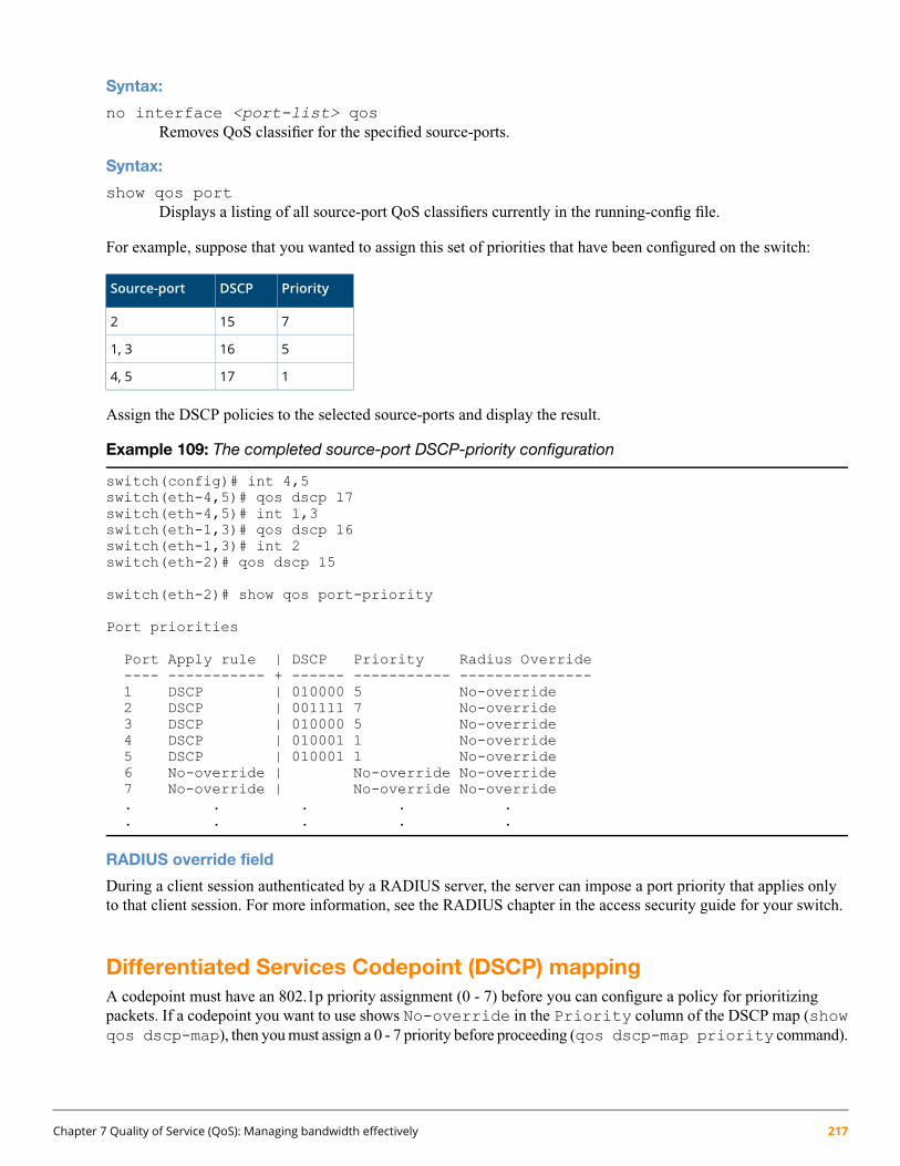
Syntax:
no interface <port-list> qosRemoves QoS classifier for the specified source-ports.
Syntax:
show qos portDisplays a listing of all source-port QoS classifiers currently in the running-config file.
For example, suppose that you wanted to assign this set of priorities that have been configured on the switch:
PriorityDSCPSource-port
7152
5161, 3
1174, 5
Assign the DSCP policies to the selected source-ports and display the result.
Example 109: The completed source-port DSCP-priority configuration
switch(config)# int 4,5switch(eth-4,5)# qos dscp 17switch(eth-4,5)# int 1,3switch(eth-1,3)# qos dscp 16switch(eth-1,3)# int 2switch(eth-2)# qos dscp 15
switch(eth-2)# show qos port-priority
Port priorities
Port Apply rule | DSCP Priority Radius Override---- ----------- + ------ ----------- ---------------1 DSCP | 010000 5 No-override2 DSCP | 001111 7 No-override3 DSCP | 010000 5 No-override4 DSCP | 010001 1 No-override5 DSCP | 010001 1 No-override6 No-override | No-override No-override7 No-override | No-override No-override. . . . .. . . . .
RADIUS override field
During a client session authenticated by a RADIUS server, the server can impose a port priority that applies onlyto that client session. For more information, see the RADIUS chapter in the access security guide for your switch.
Differentiated Services Codepoint (DSCP) mappingA codepoint must have an 802.1p priority assignment (0 - 7) before you can configure a policy for prioritizingpackets. If a codepoint you want to use shows No-override in the Priority column of the DSCP map (showqos dscp-map), then you must assign a 0 - 7 priority before proceeding (qos dscp-map priority command).
Chapter 7 Quality of Service (QoS): Managing bandwidth effectively 217

The DSCP Policy Table associates an 802.1p priority with a specific ToS byte codepoint in an IPv4 packet. Thisenables you to set a LAN policy that operates independently of 802.1Q VLAN-tagging.
A partial display of the default DSCP Policy Table is show in Table 23
You can use the following command to list the current DSCP Policy table.
Syntax:show qos dscp-map
Displays the DSCP Policy Table.
Table 23: Partial display from the default DSCP Policy Table
DSCP Policy name802.1p tagDSCP ValueDSCP CodePoint
cs000000000
01000001
02000010
03000011
04000100
05000101
06000110
07000111
cs118001000
19001001
af11110001010
111001011
af12112001100
113001101
af13114001110
115001111
cs2216010000
217010001
af21218010010
219010011
Configuring DSCP policies for codepointsUse the following commands to configure or reconfigure DSCP policies for codepoints.
Syntax:
qos dscp-map <codepoint> priority <0-7> [name <ascii-string>](Optional) This command is required only if an 802.1p priority is not already assigned to the specified<codepoint> in the DSCP Policy table (see Table 23 (page 218)).
218 HPE ArubaOS-Switch Advanced Traffic Management Guide for WC.16.02

Valid values for a DSCP codepoint are as follows:
• A binary value for the 6-bit codepoint from 000000 to 111111.
• A decimal value from 0 (low priority) to 63 (high priority) that corresponds to a binary DSCPbit set
• An ASCII standard (hexadecimal) name for a binary DSCP bit set.
Enter ? to display the list of valid codepoint entries.
When the switch applies the specified DSCP policy to a packet, the priority determines thepacket's queue in the outbound port to which it is sent. If the packet leaves the switch on atagged port, it carries the 802.1p priority with it to the next downstream device. For IP packets,the DSCP will be replaced by the codepoint specified in this command.
no qos dscp-map <codepoint>Reconfigures the 802.1p priority for <codepoint> to No-override. Also deletes the codepointpolicy name, if configured.
no qos dscp-map <codepoint> nameDeletes only the policy name, if configured, for <codepoint>.
Chapter 7 Quality of Service (QoS): Managing bandwidth effectively 219

Steps for configuring codepoints:
1. Determine whether the DSCPs already have priority assignments, which could indicate use by existingapplications. (Also, a DSCP must have a priority configured before you can assign any QoS classifiers to useit.)
Figure 37: Display the current DSCP map configuration
220 HPE ArubaOS-Switch Advanced Traffic Management Guide for WC.16.02

2. Configure the DSCP policies for the codepoints you want to use.
Figure 38: Assign priorities to the selected DSCPs
Default priority settings for selected codepointsIn a few cases, such as 001010 (af21) and 001100 (af43), a default policy (implied by the DSCP standards forAssured-Forwarding and Expedited-Forwarding) is used.
You can change the priorities for the default policies by using qos dscp-map <codepoint> priority<0-7>. (These policies are not in effect unless you have either applied the policies to a QoS classifier or configuredQoS Type-of-Service to be in diff-services mode.)
Quickly listing non-default codepoint settings
Table 23 (page 218) lists the switch’s default codepoint/priority settings. If you change the priority of any codepointsetting to a non-default value and then execute write memory, the switch will list the non-default setting in theshow config display. For example, in the default configuration, the following codepoint settings are true:
Default priorityCodepoint
1001100
No-override001101
2001110
If you change all three settings to a priority of 3, and then execute write memory, the switch will reflect thesechanges in the show config listing:
Chapter 7 Quality of Service (QoS): Managing bandwidth effectively 221

Figure 39: Example of show config listing with non-default priority settings in the DSCP table
Effect of No-override: In the QoS Type-of-Service differentiated services mode, a No-override assignmentfor the codepoint of an outbound packet means that QoS is effectively disabled for such packets. That is, QoS doesnot affect the packet queuing priority or VLAN tagging.
In this case, the packets are handled as follows (as long as no other QoS feature creates priority assignments forthem):
Outbound 802.1p priority802.1Q status
UnchangedReceived and Forwarded on a tagged port member of a VLAN.
0 (zero)—”normal”Received on an Untagged port member of a VLAN; Forwarded on a taggedport member of a VLAN.
NoneForwarded on an Untagged port member of a VLAN.
Note on changing a priority settingIf a QoS classifier is using a policy (codepoint and associated priority) in the DSCP Policy table, you must deleteor change this usage before you can change the priority setting on the codepoint. Otherwise the switch blocks thechange and displays this message:
Cannot modify DSCP Policy < codepoint > - in use by otherqos rules.
In this case, use show qos <classifier> to identify the specific classifiers using the policy you want tochange; that is:
show qos device-priority
show qos port-priority
show qos tcp-udp-port-priority
show qos vlan-priority
show qos type-of-service
For example, suppose that the 000001 (dscp 1) codepoint has a priority of 6, and several classifiers use the 000001codepoint to assign a priority to their respective types of traffic. If you wanted to change the priority of codepoint000001, you would do the following:1. Identify which QoS classifiers use the codepoint.2. Change the classifier configurations by assigning them to a different DSCP policy, or to an 802.1p priority, or
to No-override.
222 HPE ArubaOS-Switch Advanced Traffic Management Guide for WC.16.02
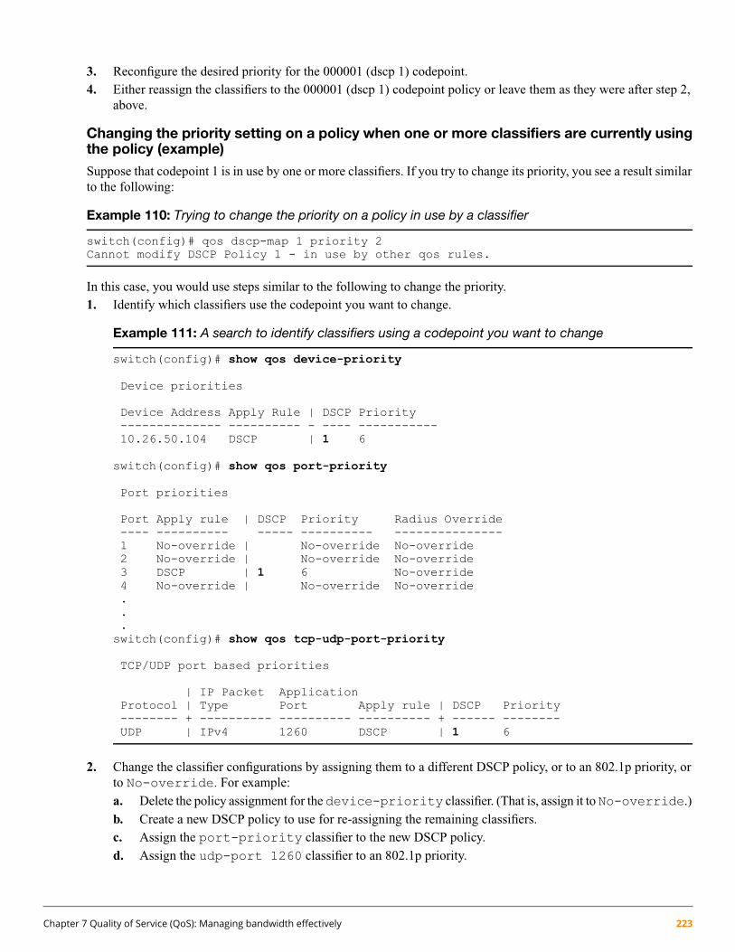
3. Reconfigure the desired priority for the 000001 (dscp 1) codepoint.4. Either reassign the classifiers to the 000001 (dscp 1) codepoint policy or leave them as they were after step 2,
above.
Changing the priority setting on a policy when one or more classifiers are currently usingthe policy (example)
Suppose that codepoint 1 is in use by one or more classifiers. If you try to change its priority, you see a result similarto the following:
Example 110: Trying to change the priority on a policy in use by a classifier
switch(config)# qos dscp-map 1 priority 2Cannot modify DSCP Policy 1 - in use by other qos rules.
In this case, you would use steps similar to the following to change the priority.1. Identify which classifiers use the codepoint you want to change.
Example 111: A search to identify classifiers using a codepoint you want to change
switch(config)# show qos device-priority
Device priorities
Device Address Apply Rule | DSCP Priority-------------- ---------- - ---- -----------10.26.50.104 DSCP | 1 6
switch(config)# show qos port-priority
Port priorities
Port Apply rule | DSCP Priority Radius Override---- ---------- ----- ---------- ---------------1 No-override | No-override No-override2 No-override | No-override No-override3 DSCP | 1 6 No-override4 No-override | No-override No-override...switch(config)# show qos tcp-udp-port-priority
TCP/UDP port based priorities
| IP Packet ApplicationProtocol | Type Port Apply rule | DSCP Priority-------- + ---------- ---------- ---------- + ------ --------UDP | IPv4 1260 DSCP | 1 6
2. Change the classifier configurations by assigning them to a different DSCP policy, or to an 802.1p priority, orto No-override. For example:a. Delete the policy assignment for thedevice-priority classifier. (That is, assign it toNo-override.)b. Create a new DSCP policy to use for re-assigning the remaining classifiers.c. Assign the port-priority classifier to the new DSCP policy.d. Assign the udp-port 1260 classifier to an 802.1p priority.
Chapter 7 Quality of Service (QoS): Managing bandwidth effectively 223
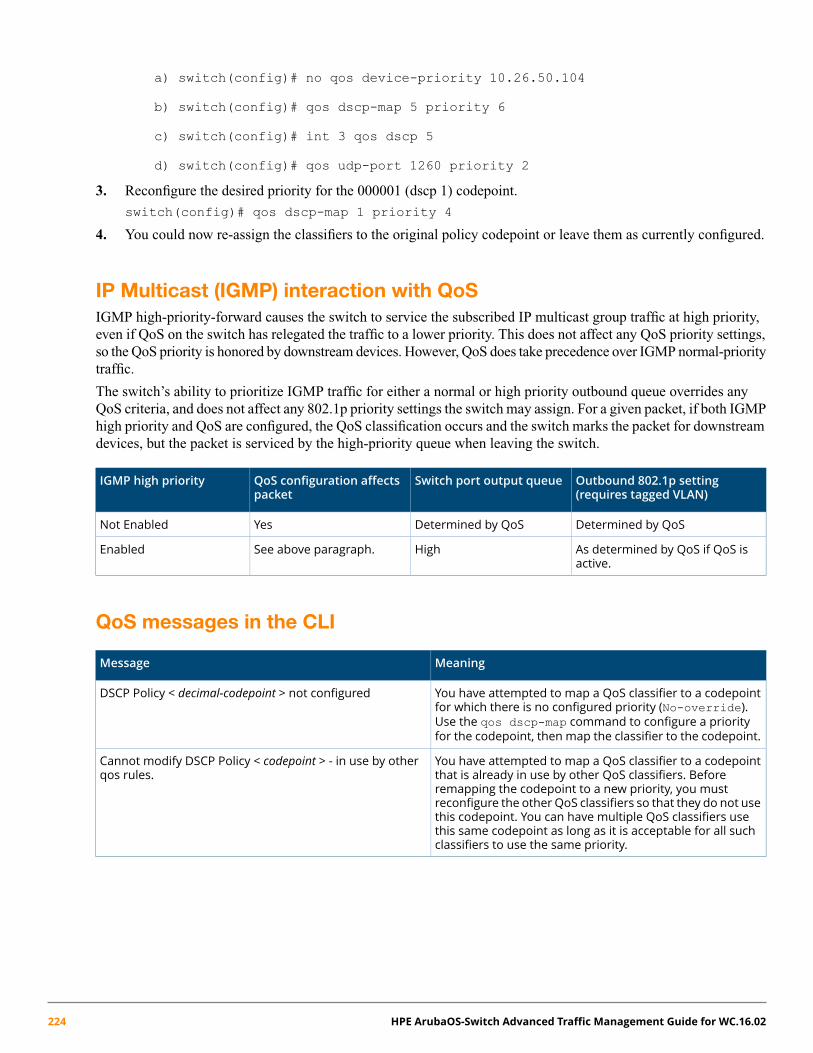
a) switch(config)# no qos device-priority 10.26.50.104
b) switch(config)# qos dscp-map 5 priority 6
c) switch(config)# int 3 qos dscp 5
d) switch(config)# qos udp-port 1260 priority 2
3. Reconfigure the desired priority for the 000001 (dscp 1) codepoint.
switch(config)# qos dscp-map 1 priority 4
4. You could now re-assign the classifiers to the original policy codepoint or leave them as currently configured.
IP Multicast (IGMP) interaction with QoSIGMP high-priority-forward causes the switch to service the subscribed IP multicast group traffic at high priority,even if QoS on the switch has relegated the traffic to a lower priority. This does not affect any QoS priority settings,so the QoS priority is honored by downstream devices. However, QoS does take precedence over IGMP normal-prioritytraffic.
The switch’s ability to prioritize IGMP traffic for either a normal or high priority outbound queue overrides anyQoS criteria, and does not affect any 802.1p priority settings the switch may assign. For a given packet, if both IGMPhigh priority and QoS are configured, the QoS classification occurs and the switch marks the packet for downstreamdevices, but the packet is serviced by the high-priority queue when leaving the switch.
Outbound 802.1p setting(requires tagged VLAN)
Switch port output queueQoS configuration affectspacket
IGMP high priority
Determined by QoSDetermined by QoSYesNot Enabled
As determined by QoS if QoS isactive.
HighSee above paragraph.Enabled
QoS messages in the CLI
MeaningMessage
You have attempted to map a QoS classifier to a codepointfor which there is no configured priority (No-override).
DSCP Policy < decimal-codepoint > not configured
Use the qos dscp-map command to configure a priorityfor the codepoint, then map the classifier to the codepoint.
You have attempted to map a QoS classifier to a codepointthat is already in use by other QoS classifiers. Before
Cannot modify DSCP Policy < codepoint > - in use by otherqos rules.
remapping the codepoint to a new priority, you mustreconfigure the other QoS classifiers so that they do not usethis codepoint. You can have multiple QoS classifiers usethis same codepoint as long as it is acceptable for all suchclassifiers to use the same priority.
224 HPE ArubaOS-Switch Advanced Traffic Management Guide for WC.16.02

QoS queue configurationQoS queue configuration allows you to reduce the number of outbound queues that all switch ports will use to bufferpackets for 802.1p user priorities. By default, there are four priority queues or traffic classes. Using this feature, youcan reconfigure the switch to eight-queue mode, or two-queue mode, to increase the available bandwidth per queue.
Use the following commands to change the number of queues per port and display the current priority queueconfiguration on the switch.
Syntax:qos queue-config < 2-queues | 4-queues | 8-queues>
Configures the number of outbound priority queues for all ports on the switch using one of thefollowing options: 2-queues, 4-queues, or 8-queues.
(Default: 8-queues)
This command will execute a write memory followed by an immediate reboot, replacing theStartup configuration with the content of the current Running configuration.
The new configuration will:
• Remove any previously configured bandwidth-min output settings
• Set the new number of outbound port queues
If you select anything but ‘yes’ for this operation, the operation is aborted and a message statingOperation aborted appears.
Syntax:show qos queue config
Displays the current qos queue configuration.
Mapping of outbound port queuesThis table shows the mapping of 802.1p priorities to outbound port queues:
Table 24: Mapping 802.1p priorities to outbound port queues
2 Queues4 Queues8 Queues(default)
802.1ppriority
1
111 (lowest)
22
230 (normal)
43
2
354
65
476
87 (highest)
Chapter 7 Quality of Service (QoS): Managing bandwidth effectively 225
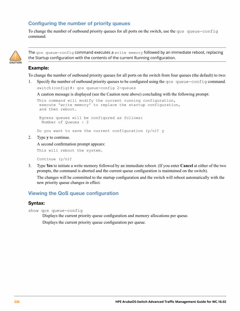
Configuring the number of priority queuesTo change the number of outbound priority queues for all ports on the switch, use the qos queue-configcommand.
The qos queue-config command executes a write memory followed by an immediate reboot, replacingthe Startup configuration with the contents of the current Running configuration.
Example:
To change the number of outbound priority queues for all ports on the switch from four queues (the default) to two:
1. Specify the number of outbound priority queues to be configured using the qos queue-config command.
switch(config)#: qos queue-config 2-queues
A caution message is displayed (see the Caution note above) concluding with the following prompt:
This command will modify the current running configuration,execute 'write memory' to replace the startup configuration,and then reboot.
Egress queues will be configured as follows:Number of Queues : 2
Do you want to save the current configuration (y/n)? y
2. Type y to continue.
A second confirmation prompt appears:
This will reboot the system.
Continue (y/n)?
3. Type Yes to initiate a write memory followed by an immediate reboot. (If you enter Cancel at either of the twoprompts, the command is aborted and the current queue configuration is maintained on the switch).
The changes will be committed to the startup configuration and the switch will reboot automatically with thenew priority queue changes in effect.
Viewing the QoS queue configuration
Syntax:
show qos queue-configDisplays the current priority queue configuration and memory allocations per queue.
Displays the current priority queue configuration per queue.
226 HPE ArubaOS-Switch Advanced Traffic Management Guide for WC.16.02

Example 112: Viewing QoS queue configuration
switch#: show qos queue-config
Outbound Port Queue Configuration
802.1pQueue Priority----- --------1 0-32 4-7
QoS port egress-queue drop countersPort egress-queue drop counters help customers debug network behavior and performance issues.
Egress-queue drop counters can be used to detect congestion on outbound ports, and help troubleshoot the network.The additional status display by this command show egress port-queue drop and transmits, the sumof which should be all traffic intended for the outbound port.
Syntax:
show interfaces queues... | config | custom ... | display |port-utilization | transceiver ... | status ... | tunnel ... |ethernet PORT-LIST
Show port configuration and status information.
Chapter 7 Quality of Service (QoS): Managing bandwidth effectively 227

Example 113: show interfaces ...
show interface queues a1Status and Counters - Port Counters for port A1
Name :MAC Address : a01d48-8f99ffLink Status : DownPort Totals (Since boot or last clear) :
Rx Packets : 0 Tx Packets : 0Rx Bytes : 0 Tx Bytes : 0Rx Drop Packets : 0 Tx Drop Packets : 0Rx Drop Bytes : 0 Tx Drop Bytes : 0
Egress Queue Totals (Since boot or last clear) :Tx Packets Dropped Packets Tx Bytes Dropped BytesQ1 123456789012 123456789012 123456789012 123456789012Q2 12345678 12345678 12345678 12345678Q3 1234 1234 1234 1234Q4 0 0 0 0
QoS operating notes and restrictionsTable 25: Details of packet criteria and restrictions for QoS support
DSCPoverwrite(re-marking)
QoS Classifiers
Packetcriteria orrestriction
Incoming802.1p
SourceportVLANLayer 3Protocol
IP ToSDevicepriority (IPaddress)
UDP/TCP
YesNoNoNoNoYesYesYes
Restrictedto IPv4packetsonly
NoYesYesYesYesYesYesYes
Allowpacketswith IPoptions1
NoYesYesYesYesNoNoNoSupportIPv6packets
1 For explicit QoS support of IPv6 packets, force IPv6 traffic into its own set of VLANs and then configure VLAN-based classifiers for those
VLANs.
• All switches: For explicit QoS support of IP subnets, Hewlett Packard Enterprise recommends forcing IPsubnets onto separate VLANs and then configuring VLAN-based classifiers for those VLANs.
• For devices that do not support 802.1Q VLAN-tagged ports: For communication between these devicesand the switch, connect the device to a switch port configured as Untagged for the VLAN in which you wantthe device's traffic to move.
• Port tagging rules: For a port on the switch to be a member of a VLAN, the port must be configured as eitherTagged or Untagged for that VLAN. A port can be an untagged member of only one VLAN of a givenprotocol type. Otherwise, the switch cannot determine which VLAN should receive untagged traffic.
228 HPE ArubaOS-Switch Advanced Traffic Management Guide for WC.16.02

• Maximum QoS configuration entries: The switches covered in this guide accept the maximum outboundpriority and/or DSCP policy configuration entries shown in the following table:
Table 26: Maximum QoS entries
NotesMaximum QoS entries ofone type
Softwareversion
Switch
WB.16.02Switch 2920
Table 27: Maximum QoS entries
NotesMaximum QoS entries ofone type
SoftwareversionSwitch
3001WB.16.02Switch 2930 ◦ Each device (IP address) QoS configuration usestwo entries.
◦ Each TCP/UDPport QoS configuration uses fourentries.
◦ All other classifier configurations use one entryeach.
1 Configuring device (IP address), TCP/UDP QoS entries, or other entries reduces this maximum. See the “Notes” column.
Attempting to exceed the above limits generates the following message in the CLI:
Unable to add this QoS rule. Maximum number (entry-#) already reached.
• Not supported: Use of an inbound 802.1p packet priority as a classifier for remapping a packet's outboundpriority to different 802.1p priority. For example, where inbound packets carry an 802.1p priority of 1, QoScannot be configured use this priority as a classifier for changing the outbound priority to 0.
• Monitoring shared resources: The QoS feature shares internal switch resources with several other features.For information on determining the current resource availability and usage, see “Monitoring Resources” in themanagement and configuration guide for your switch.
Chapter 7 Quality of Service (QoS): Managing bandwidth effectively 229

Chapter 8
Rapid per-VLAN spanning tree (RPVST+) operation
For conceptual information on RPVST+, see “About RPVST+” (page 264).
Overview
For information on configuring basic and multiple instance spanning tree, see “Multiple Instance SpanningTree Operation” (page 104).
RPVST+ is a proprietary spanning tree implementation that extends RSTP (802.1w) to run a separate spanning treefor each VLAN on the switch, and ensures that only one active, loop-free path exists between any two nodes on agiven VLAN.
General steps for configuring RPVST+The general steps for configuring RPVST+ via the CLI are:
1. Select RPVST+ as the active spanning tree mode by entering the following command:spanning-tree mode rapid-pvst
To begin with the default RPVST+ configuration (recommended), go to step 6.
2. Configure global spanning tree parameters.3. Configure per-VLAN parameters.4. Configure per-port per-VLAN parameters. These commands affect RPVST+ operation on traffic associated
with the specified VLANs through the specified ports.5. Configure per-port parameters. These commands affect RPVST+ operation for all traffic through the specified
ports.6. Use one of the following commands to enable RPVST+ spanning tree operation on the switch:
• One or more selected VLANs: spanning-tree vlan <vid-list>
• The first 64 VLANs: spanning-tree
Any VLANs in excess of the first 64 would have RPVST+ disabled. In this case, use the [no]spanning-tree vlan <vid-list> command to change the mix of RPVST+ enabled and disabledVLANs.
Additional configuration options include:
• “Configuring BPDU filtering” (page 113)
• “Allowing traffic on VLAN ID (PVID) mismatched links” (page 239)
• “Configuring STP loop guard” (page 240)
230 HPE ArubaOS-Switch Advanced Traffic Management Guide for WC.16.02

Configuring RPVST+
Selecting RPVST+ as the spanning tree mode
Syntax:
[no] spanning-tree mode [ mstp | rapid-pvst ]Specifies that spanning tree will run in MSTP (default) or RPVST+ mode.
To view Mode, use the show run command. This will eliminate confusion if there is an RPVSTconfiguration but MSTP is running. This will lead to a change in the existing factory default setting.
RPVST+ parameters can be configured even if the mode is MSTP and vice versa. This commanddoes not enable/disable spanning tree. It sets the mode which is operational once spanning tree isenabled using spanning-tree enable.
The no form of the command changes the spanning tree mode to the default mode (MSTP)
Configuring global spanning tree
Syntax:
spanning-tree extend system-idCreates a unique bridge identifier for each VLAN by adding the VLAN ID (vid) value to the priorityfield of the bridge identifier in every RPVST+ BPDU.
Syntax
[no]spanning-tree log state-transitions [ instance <instance-id> cst ]
Command enables/disables event logging for port-block events.
List of VLAN identifiers
Range: <instance-id> 1–16
[vlan <vid-list>]
Syntax:
[no] spanning-tree ignore-pvid-inconsistencyCauses the switch to ignore per-VLAN ID inconsistencies when the ports on both ends of apoint-to-point link are untagged members of different VLANs, thus allowing RPVST+ to run onthe mismatched links. On a given switch, affects all ports belonging to VLANs on which RPVST+is enabled. See “Allowing traffic on VLAN ID (PVID) mismatched links” (page 239).
Default: Disabled
Syntax:
[no] spanning-tree bpdu-protection-timeout <timeout>Configures the duration of time when protected ports receiving unauthorized BPDUs will remaindisabled. The default value of 0 (zero) sets an infinite timeout (that is, ports that are disabled bybpdu-protection are not, by default, re-enabled automatically).
Default: 0
Range: 0 - 65535 seconds
Chapter 8 Rapid per-VLAN spanning tree (RPVST+) operation 231
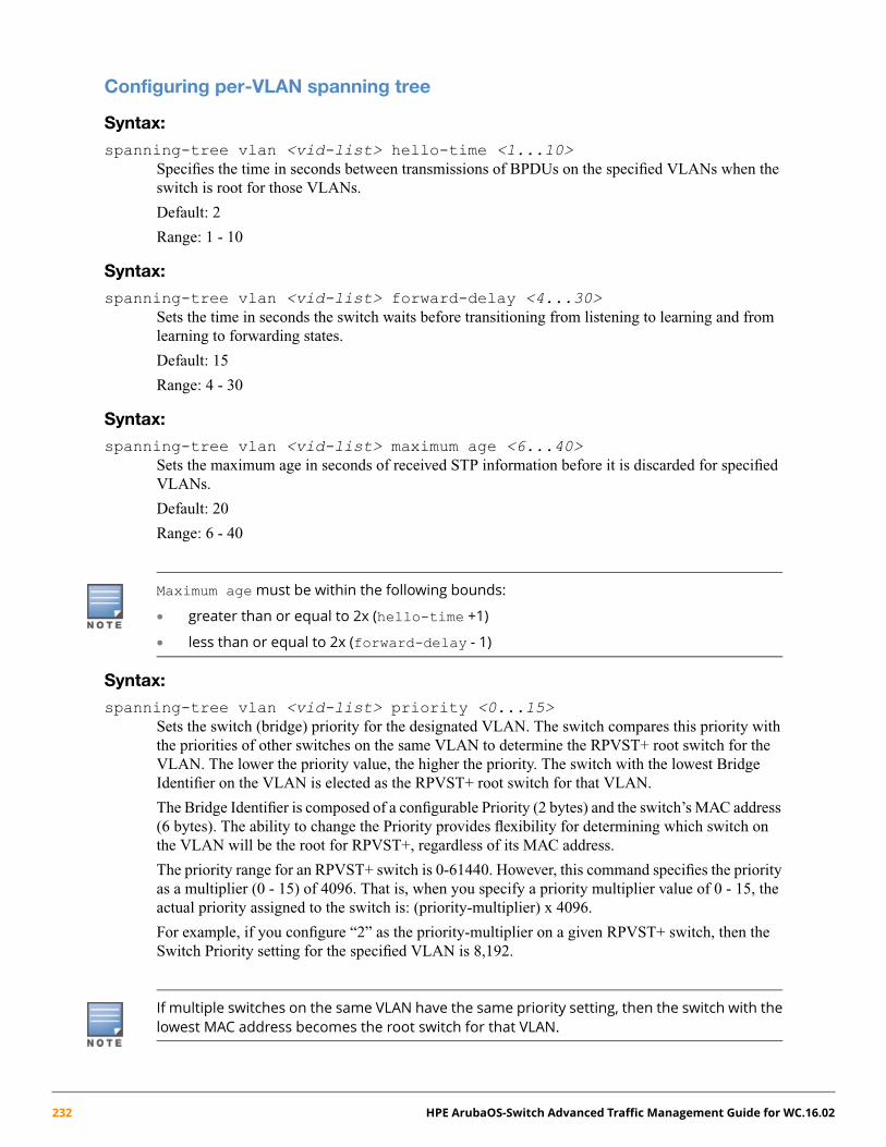
Configuring per-VLAN spanning tree
Syntax:
spanning-tree vlan <vid-list> hello-time <1...10>Specifies the time in seconds between transmissions of BPDUs on the specified VLANs when theswitch is root for those VLANs.
Default: 2
Range: 1 - 10
Syntax:
spanning-tree vlan <vid-list> forward-delay <4...30>Sets the time in seconds the switch waits before transitioning from listening to learning and fromlearning to forwarding states.
Default: 15
Range: 4 - 30
Syntax:
spanning-tree vlan <vid-list> maximum age <6...40>Sets the maximum age in seconds of received STP information before it is discarded for specifiedVLANs.
Default: 20
Range: 6 - 40
Maximum agemust be within the following bounds:
• greater than or equal to 2x (hello-time +1)
• less than or equal to 2x (forward-delay - 1)
Syntax:
spanning-tree vlan <vid-list> priority <0...15>Sets the switch (bridge) priority for the designated VLAN. The switch compares this priority withthe priorities of other switches on the same VLAN to determine the RPVST+ root switch for theVLAN. The lower the priority value, the higher the priority. The switch with the lowest BridgeIdentifier on the VLAN is elected as the RPVST+ root switch for that VLAN.
The Bridge Identifier is composed of a configurable Priority (2 bytes) and the switch’s MAC address(6 bytes). The ability to change the Priority provides flexibility for determining which switch onthe VLAN will be the root for RPVST+, regardless of its MAC address.
The priority range for an RPVST+ switch is 0-61440. However, this command specifies the priorityas a multiplier (0 - 15) of 4096. That is, when you specify a priority multiplier value of 0 - 15, theactual priority assigned to the switch is: (priority-multiplier) x 4096.
For example, if you configure “2” as the priority-multiplier on a given RPVST+ switch, then theSwitch Priority setting for the specified VLAN is 8,192.
If multiple switches on the same VLAN have the same priority setting, then the switch with thelowest MAC address becomes the root switch for that VLAN.
232 HPE ArubaOS-Switch Advanced Traffic Management Guide for WC.16.02
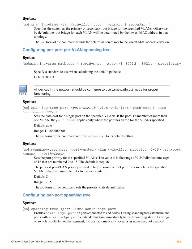
Syntax:
[no] spanning-tree vlan <vid-list> root [ primary | secondary ]Specifies the switch as the primary or secondary root bridge for the specified VLANs. Otherwise,by default, the root bridge for each VLAN will be determined by the lowest MAC address in thattopology.
The no form of the command returns the determination of root to the lowest MAC address criterion.
Configuring per-port per-VLAN spanning tree
Syntax
[no]spanning-tree pathcost < rapid-pvst | mstp > [ 8021d | 8021t | proprietary]
Specify a standard to use when calculating the default pathcost.
Default: 8021t
All devices in the network should be configure to use same pathcost mode for properfunctioning.
Syntax:
[no] spanning-tree port <port-number> vlan <vid-list> path-cost [ auto |<1...200000000> ]
Sets the path cost for a single port on the specified VLANs. If the port is a member of more thanone VLAN, the path-cost applies only where the port has traffic for the VLANs specified.
Default: auto
Range: 1 - 200000000
The no form of the command returns path-cost to its default setting.
Syntax:
[no] spanning-tree port <port-number> vlan <vid-list> priority <0-15> path-cost<auto> | <Path-Cost>
Sets the port priority for the specified VLANs. The value is in the range of 0-240 divided into stepsof 16 that are numbered 0 to 15. The default is step 16.
The per-port per-VLAN priority is used to help choose the root port for a switch on the specifiedVLAN if there are multiple links to the root switch.
Default: 8
Range 0 - 15
The no form of the command sets the priority to its default value.
Configuring per-port spanning tree
Syntax:
[no] spanning-tree <port-list> admin-edge-portEnables admin-edge-port on ports connected to end nodes. During spanning tree establishment,ports with admin-edge-port enabled transition immediately to the forwarding state. If a bridgeor switch is detected on the segment, the port automatically operates as non-edge, not enabled.
Chapter 8 Rapid per-VLAN spanning tree (RPVST+) operation 233
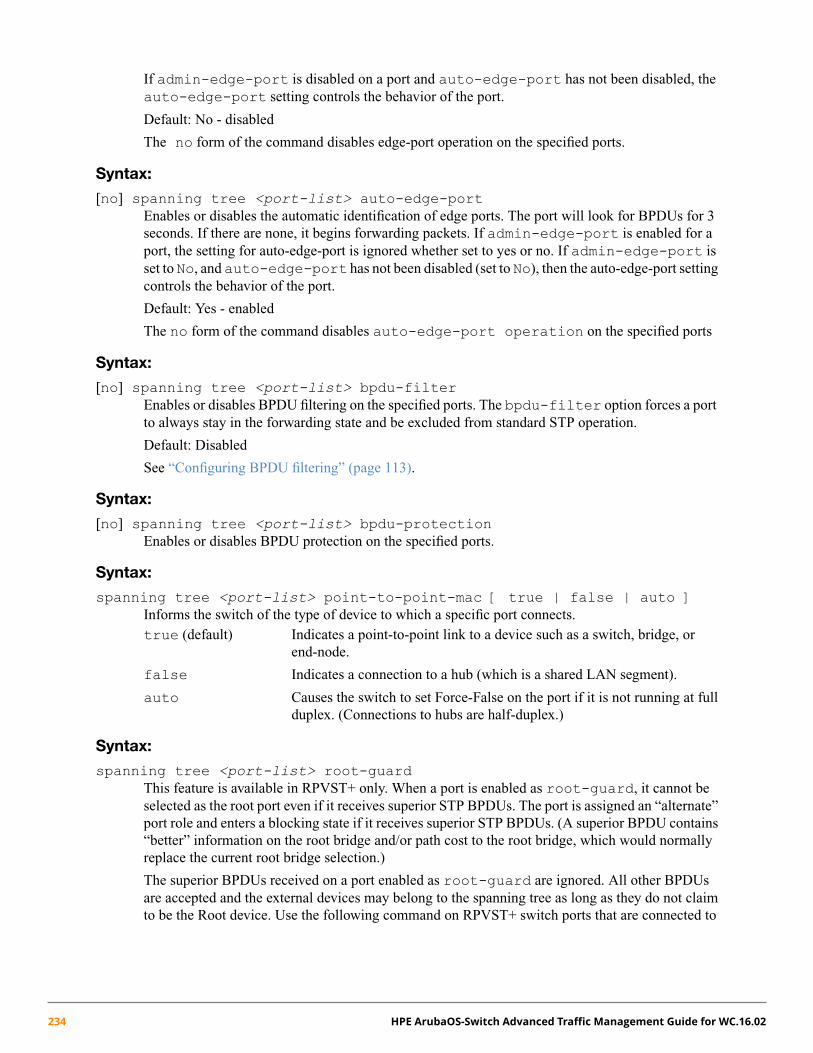
If admin-edge-port is disabled on a port and auto-edge-port has not been disabled, theauto-edge-port setting controls the behavior of the port.
Default: No - disabled
The no form of the command disables edge-port operation on the specified ports.
Syntax:
[no] spanning tree <port-list> auto-edge-portEnables or disables the automatic identification of edge ports. The port will look for BPDUs for 3seconds. If there are none, it begins forwarding packets. If admin-edge-port is enabled for aport, the setting for auto-edge-port is ignored whether set to yes or no. If admin-edge-port isset to No, and auto-edge-port has not been disabled (set to No), then the auto-edge-port settingcontrols the behavior of the port.
Default: Yes - enabled
The no form of the command disables auto-edge-port operation on the specified ports
Syntax:
[no] spanning tree <port-list> bpdu-filterEnables or disables BPDU filtering on the specified ports. The bpdu-filter option forces a portto always stay in the forwarding state and be excluded from standard STP operation.
Default: Disabled
See “Configuring BPDU filtering” (page 113).
Syntax:
[no] spanning tree <port-list> bpdu-protectionEnables or disables BPDU protection on the specified ports.
Syntax:
spanning tree <port-list> point-to-point-mac [ true | false | auto ]Informs the switch of the type of device to which a specific port connects.true (default) Indicates a point-to-point link to a device such as a switch, bridge, or
end-node.
false Indicates a connection to a hub (which is a shared LAN segment).
auto Causes the switch to set Force-False on the port if it is not running at fullduplex. (Connections to hubs are half-duplex.)
Syntax:
spanning tree <port-list> root-guardThis feature is available in RPVST+ only. When a port is enabled as root-guard, it cannot beselected as the root port even if it receives superior STP BPDUs. The port is assigned an “alternate”port role and enters a blocking state if it receives superior STP BPDUs. (A superior BPDU contains“better” information on the root bridge and/or path cost to the root bridge, which would normallyreplace the current root bridge selection.)
The superior BPDUs received on a port enabled as root-guard are ignored. All other BPDUsare accepted and the external devices may belong to the spanning tree as long as they do not claimto be the Root device. Use the following command on RPVST+ switch ports that are connected to
234 HPE ArubaOS-Switch Advanced Traffic Management Guide for WC.16.02

devices located in other administrative network domains to ensure the stability of the core RPVST+network topology so that undesired or damaging influences external to the network do not enter.
Default: Disabled.
Syntax:
spanning-tree <port-list> tcn-guardWhen tcn-guard is enabled for a port, it causes the port to stop processing or propagating receivedtopology change notifications and topology changes to other ports.
Default: Disabled.
Enabling or disabling RPVST+ spanning treeWith the spanning tree mode set to RPVST+, you can do either of the following:
• Enable or disable RPVST+ on all VLANs on the switch.
• Enable or disable RPVST+ on specified VLANs that are RPVST+-enabled on the switch.
Syntax:
[no] spanning-tree [ enable | disable ]
To globally enable RPVST+ on all VLANs on the switch, use either of the following:
spanning-tree [enable][no] spanning-tree disable
To globally disable RPVST+ on all VLANs on the switch, use any of the following:
[no] spanning-treespanning-tree disable[no] spanning-tree enable
This status will always be shown in show run to let you know whether the spanning-tree is enabled. Havingspanning tree present but not enabled will lead to a change in the existing factory default settings.
This command overrides the per-VLAN enable/disable command (below).
Syntax:
spanning-tree vlan <vid list> [ enable | disable ]To enable RPVST+ on one or more VLANs on the switch, use either of the following:spanning-tree vlan <vid list> enable[no] spanning-tree vlan <vid list> disable
To disable RPVST+ on one or more VLANs on the switch, use any of the following:
[no] spanning-tree vlan <vid-list>spanning-tree vlan <vid> disable[no] spanning-tree vlan <vid-list> enable
Chapter 8 Rapid per-VLAN spanning tree (RPVST+) operation 235
BPDU filteringThe STP BPDU filter feature allows control of spanning tree participation on a per-port basis. It can be used toexclude specific ports from becoming part of spanning tree operations. A port with the BPDU filter enabled willignore incoming BPDU packets on all VLANs where the port is a member, and stay locked in the spanning treeforwarding state. All other ports will maintain their role.
Syntax:[no] spanning-tree [ <port-list> | all ] bpdu-filter
Enables/disables BPDU filtering on the specified ports. The bpdu-filter option forces a portto always stay in the forwarding state and be excluded from standard STP operation.
Sample scenarios in which this feature may be used:
• To have STP operations running on selected ports of the switch rather than every port of theswitch at a time.
• To prevent the spread of errant BPDU frames.
• To eliminate the need for a topology change when a port's link status changes. For example,ports that connect to servers and workstations can be configured to remain outside of spanningtree operations.
• To protect the network from denial of service attacks that use spoofing BPDUs by droppingincoming BPDU frames. For this scenario, BPDU protection offers a more secure alternative,implementing port shutdown and a detection alert when errant BPDU frames are received.
Ports configured with the BPDU filter mode remain active (learning and forward frames).However, spanning tree cannot receive or transmit BPDUs on the port. The port remains in aforwarding state, permitting all broadcast traffic. This can create a network storm if there areany loops (that is, redundant links) using these ports. If you suddenly have a high load, disconnectthe link and disable the BPDU filter (using the no command.)
Example 114: Configure BPDU filtering
To configure BPDU filtering on ports 23 and 24, enter:
switch(config)#: spanning-tree 23,24 bpdu-filter
Viewing BPDU filtering
Syntax:show spanning-tree [ethernet] <port-list> configuration
Displays the BPDU's filter state.
236 HPE ArubaOS-Switch Advanced Traffic Management Guide for WC.16.02

Example 115: Displaying BPDU filtering for specific ports within the config file
This example shows how BPDU filter state is displayed for ports 23 and 24 within the configuration file.
switch#: show spanning-tree 23,24 configSpanning Tree InformationSTP Enabled [No] : YesMode : RPVSTSwitch MAC Address : 0024a8-d60b80RPVST Enabled VLANs : 10,20
Admin Auto Admin Root Loop TCN BPDU BPDUPort Edge Edge PtP Grd Grd Grd Flt Guard----- ----- ---- ----- ---- ---- --- ---- -----23 No Yes True No No No Yes No24 No Yes True No No No Yes No
Example 116: Displaying BPDU filtering as separate entries of the spanning tree category within therunning config file
This example shows how BPDU filters per port are displayed as separate entries of the spanning tree category withinthe configuration file.
switch(config)#: show running-configRunning configuration:
spanning-treespanning-tree 23 bpdu-filterspanning-tree 24 bpdu-filterspanning-tree mode rapid-pvst
Configuring and managing BPDU protectionBPDU protection is a security feature designed to protect the active STP topology by preventing spoofed BPDUpackets from entering the STP domain. In a typical implementation, BPDU protection would be applied to edgeports connected to end-user devices that do not run STP. If STP BPDU packets are received on a protected port, thefeature will disable that port and alert the network manager via an SNMP trap as shown in Figure 40.
Chapter 8 Rapid per-VLAN spanning tree (RPVST+) operation 237

Figure 40: BPDU protection enabled at the network edge
The following commands allow you to configure BPDU protection on VLANs for which the port is a member.
Syntax:[no] spanning-tree <port-list> bpdu-protection
Enables/disables the BPDU protection feature on a port.
Default: Disabled.
Syntax:[no] spanning-tree <port-list> bpdu-protection-timeout <timeout>
Configures the duration of time when protected ports receiving unauthorized BPDUs will remaindisabled. The default value of 0 (zero) sets an infinite timeout (that is, ports that are disabled bybpdu-protection are not, by default, re-enabled automatically).
Default: 0
Range: 0 - 65535 seconds
For an example of using this command, see “Re-enabling a port blocked by BPDU protection”(page 239).
Syntax:[no] spanning-tree trap errant-bpdu
Enables/disables the sending of errant BPDU traps.
This command should only be used to guard edge ports that are not expected to participate in STP operations.Once BPDU protection is enabled, it will disable the port as soon as any BPDU packet is received on thatinterface.
238 HPE ArubaOS-Switch Advanced Traffic Management Guide for WC.16.02

Viewing BPDU protection status
Syntax:
show spanning-tree bpdu-protection <port-list>Displays a summary listing of ports with BPDU protection enabled. To display detailed per-portstatus information, enter the specific port numbers. BPDU protected ports are displayed as separateentries of the spanning tree category within the configuration file.
Example 117: Displaying BPDU protection status for specific ports
switch#: show spanning-tree bpdu-protection 23-24
Status and Counters - STP BPDU Protection Information
BPDU Protection Timeout (sec) : 0BPDU Protected Ports : 23-24
Port Type Protection State Errant BPDUs------ --------- ---------- ----------------- ------------23 100/1000T Yes Bpdu Error 124 100/1000T Yes 0
Re-enabling a port blocked by BPDU protectionPorts disabled by BPDU Protection remain disabled unless BPDU Protection is removed from the switch or byconfiguring a nonzero BPDU protection timeout. For example, if you want to re-enable protected ports 60 secondsafter receiving a BPDU, you would use this command:
switch(config)#: spanning-tree bpdu-protection-timeout 60
Allowing traffic on VLAN ID (PVID) mismatched linksWhen RPVST+ is running in the default configuration on a link where there is a VLAN ID mismatch, PVST blocksthe link, causing traffic on the mismatched VLANs to be dropped. However, there can be instances where trafficpassing between mismatched VLANs on a link is desirable. When enabled on the switch, theignore-pvid-inconsistency command allows this behavior. That is, where the ports on both ends of apoint-to-point link are untagged members of different VLANs, enablingignore-pvid-inconsistency enablesRPVST+ to process untagged RPVST+ BPDUs belonging to the peer’s untagged VLAN as if it was received on thecurrent device’s untagged VLAN
Syntax:[no] spanning-tree ignore-pvid-inconsistency
Causes the switch to ignore per-VLAN ID inconsistencies when the ports on both ends of apoint-to-point link are untagged members of different VLANs, thus allowing RPVST+ to run onthe mismatched links. On a given switch, this affects all ports belonging to VLANs on whichRPVST+ is enabled.
Default: Disabled
Chapter 8 Rapid per-VLAN spanning tree (RPVST+) operation 239

Table 28: RPVST+ behavior with ignore-pvid-inconsistency enabled
RPVST+ behavior withignore-pvid-inconsistency enabledSwitch “B” Peer port on VLAN YSwitch “A” Port on VLAN X
Forward1Untagged on VLAN 10Untagged on VLAN 10
Forward1, 2Untagged on VLAN 20Untagged on VLAN 10
DropTagged on VLAN XUntagged on VLAN X
Drop (traffic from both VLANs)Tagged on VLAN YUntagged on VLAN X
Forward1Tagged on VLAN XTagged on VLAN X
Drop (traffic from both VLANs)Tagged on VLAN YTagged on VLAN X1 Forwarding state applies if the link has not been blocked by RPVST+ as a redundant link.2 If both sides (ports) of the link are untagged to different VLANs, but the VLAN on the switch on one end of the link is not RPVST+-enabled,
untagged RPVST+ frames received on that switch port (where RPVST+ is disabled) would be forwarded to any other ports belonging to the
inbound VLAN.
Configuring STP loop guardSpanning tree is used to ensure a loop-free topology over the LAN. Occasionally a hardware or software failure cancause STP to fail, creating STP/ forwarding loops that can cause network failures where unidirectional links areused. The non-designated port transitions in a faulty manner because the port is no longer receiving STP BPDUs.
STP Loop Guard causes the non-designated port to go into the STP loop inconsistent state instead of the forwardingstate. In the loop-inconsistent state, the port prevents data traffic through the link, therefore avoiding the loop creation.When BPDUs again are received on the inconsistent port, it resumes normal STP operation automatically.
Syntax:[no] spanning-tree <port-list> loop-guard
Enables STP Loop Guard on a particular port or ports. STP Loop Guard is best applied on blockingor forwarding ports.
The no form of the command disables STP Loop Guard.
Default: Disabled
240 HPE ArubaOS-Switch Advanced Traffic Management Guide for WC.16.02
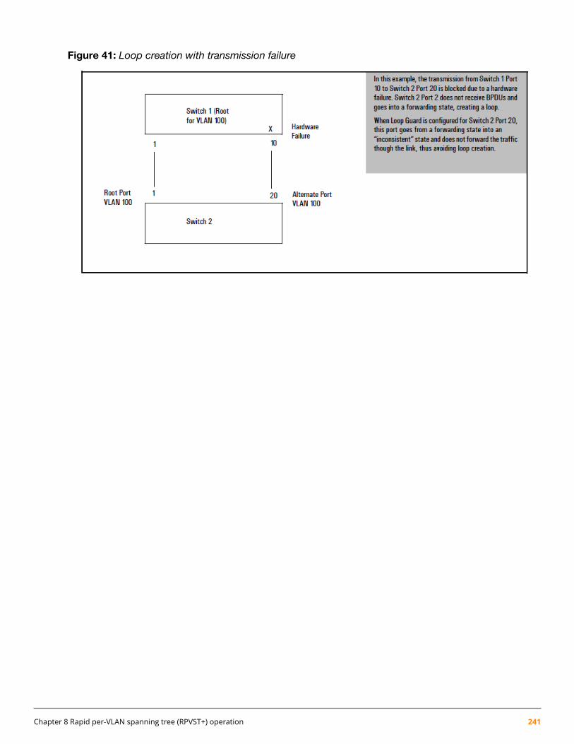
Figure 41: Loop creation with transmission failure
Chapter 8 Rapid per-VLAN spanning tree (RPVST+) operation 241

Example 118: Before configuring loop guard
Before configuring Loop Guard on port 20, the status of VLAN 20 appears as follows:
switch(config)#: show spanning-tree vlan 20
Spanning Tree Information
STP Enabled [No] : YesMode : RPVSTExtended System ID : Enabled
Ignore PVID Inconsistency : DisabledSwitch MAC Address : 002347-c651c0
VLAN ID : 20RPVST Enabled : Enabled
Root MAC Address : 0024a8-d13a40Root Priority : 32,768Root Path Cost : 20,000Root Port : 1Operational Hello Time (secs) : 2Topology Change Count : 2Time Since Last Change : 9 secs
DesignatedPort Type Cost Priority Role State Bridge----- ---------- ------ --------- ---------- ---------- ---------------1 100/1000T 20000 128 Root Forwarding 0024a8-d13a4020 10/100TX 200000 128 Alternate Blocking 002347-587b80
Example 119: After configuring loop guard
This example shows that, by executing spanning-tree 20 loop-guard, loop guard has been configured onport 20 of Switch 2:
switch(config)#: show spanning-tree
Spanning Tree Information
STP Enabled [No] : YesMode : RPVSTExtended System ID : EnabledIgnore PVID Inconsistency : DisabledRPVST Enabled VLANs : 20
Switch MAC Address : 002347-c651c0Root Guard Ports :Loop Guard Ports : 20TCN Guard Ports :BPDU Protected Ports :BPDU Filtered Ports :Auto Edge Ports : 1-24Admin Edge Ports :
242 HPE ArubaOS-Switch Advanced Traffic Management Guide for WC.16.02

VLAN Root Mac Root Root Root HelloID Address Priority Path-Cost Port Time(sec)----- --------------- ---------- ---------- -------------------- ---------100 0024a8-d13a40 32,768 20,000 1 2
Chapter 8 Rapid per-VLAN spanning tree (RPVST+) operation 243
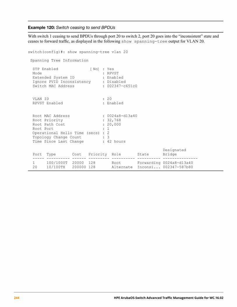
Example 120: Switch ceasing to send BPDUs
With switch 1 ceasing to send BPDUs through port 20 to switch 2, port 20 goes into the “inconsistent” state andceases to forward traffic, as displayed in the following show spanning-tree output for VLAN 20.
switch(config)#: show spanning-tree vlan 20
Spanning Tree Information
STP Enabled [No] : YesMode : RPVSTExtended System ID : EnabledIgnore PVID Inconsistency : DisabledSwitch MAC Address : 002347-c651c0
VLAN ID : 20RPVST Enabled : Enabled
Root MAC Address : 0024a8-d13a40Root Priority : 32,768Root Path Cost : 20,000Root Port : 1Operational Hello Time (secs) : 2Topology Change Count : 3Time Since Last Change : 42 hours
DesignatedPort Type Cost Priority Role State Bridge----- ---------- ------ --------- ---------- ---------- ---------------1 100/1000T 20000 128 Root Forwarding 0024a8-d13a4020 10/100TX 200000 128 Alternate Inconsi... 002347-587b80
244 HPE ArubaOS-Switch Advanced Traffic Management Guide for WC.16.02
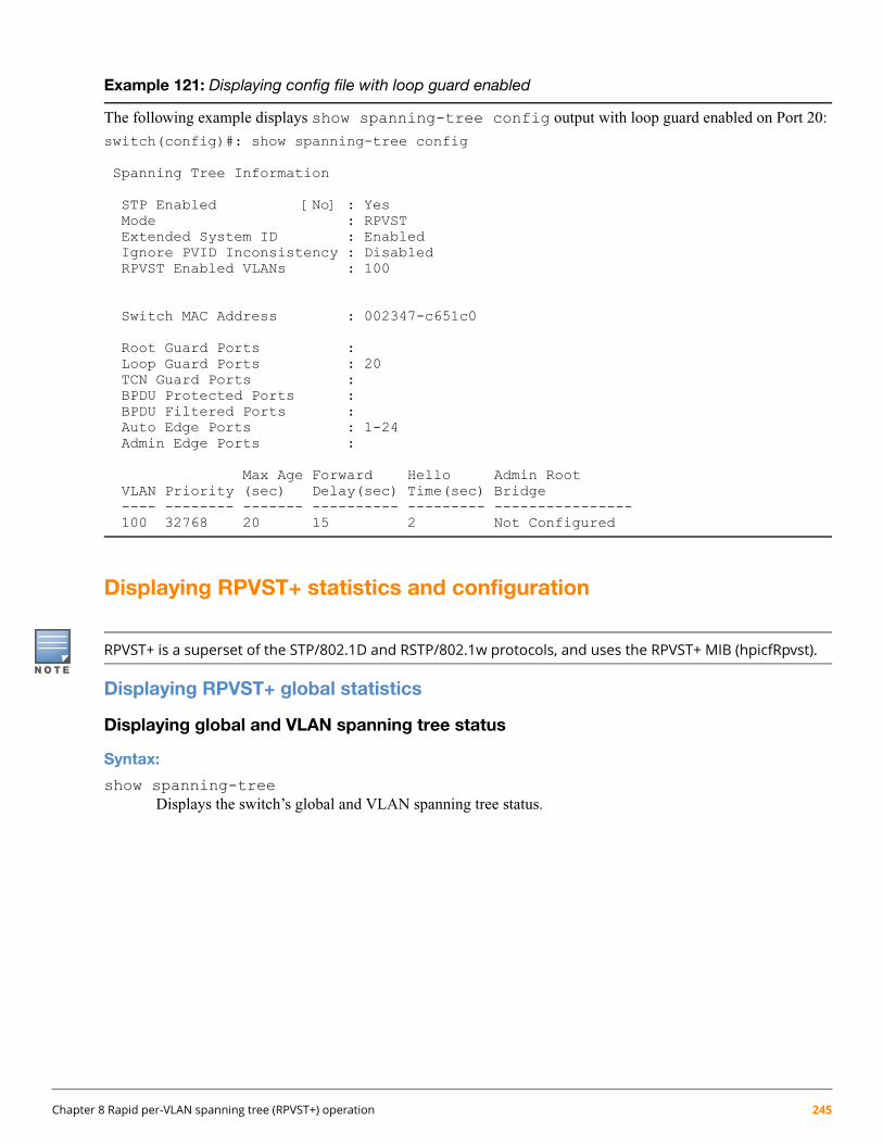
Example 121: Displaying config file with loop guard enabled
The following example displays show spanning-tree config output with loop guard enabled on Port 20:
switch(config)#: show spanning-tree config
Spanning Tree Information
STP Enabled [No] : YesMode : RPVSTExtended System ID : EnabledIgnore PVID Inconsistency : DisabledRPVST Enabled VLANs : 100
Switch MAC Address : 002347-c651c0
Root Guard Ports :Loop Guard Ports : 20TCN Guard Ports :BPDU Protected Ports :BPDU Filtered Ports :Auto Edge Ports : 1-24Admin Edge Ports :
Max Age Forward Hello Admin RootVLAN Priority (sec) Delay(sec) Time(sec) Bridge---- -------- ------- ---------- --------- ----------------100 32768 20 15 2 Not Configured
Displaying RPVST+ statistics and configuration
RPVST+ is a superset of the STP/802.1D and RSTP/802.1w protocols, and uses the RPVST+ MIB (hpicfRpvst).
Displaying RPVST+ global statistics
Displaying global and VLAN spanning tree status
Syntax:
show spanning-treeDisplays the switch’s global and VLAN spanning tree status.
Chapter 8 Rapid per-VLAN spanning tree (RPVST+) operation 245

Example 122: Displaying the switch's global and VLAN spanning tree status
switch#: show spanning-tree
Spanning Tree Information
STP Enabled [No] : YesMode : RPVSTExtended System ID : DisabledIgnore PVID Inconsistency : DisabledRPVST Enabled VLANs : 10,20
Switch MAC Address : 0024a8-d13a40Root Guard Ports :Loop Guard Ports :TCN Guard Ports :BPDU Protected Ports : 23-24BPDU Filtered Ports : 23-24Auto Edge Ports : 1-24,A1-A4Admin Edge Ports :
VLAN Root Mac Root Root Root HelloID Address Priority Path-Cost Port Time(sec)----- --------------- ---------- ---------- -------------------- ---------10 0024a8-d13a40 32,768 0 This switch is root 220 0024a8-d13a40 32,768 0 This switch is root 2
Displaying status for a specific VLAN
Syntax:
show spanning-tree vlan <vlan-id>Displays detailed spanning tree information for the VLAN and the ports belonging to the specifiedVLAN.
246 HPE ArubaOS-Switch Advanced Traffic Management Guide for WC.16.02

Example 123: Displaying status for a specific VLAN
switch#: show spanning-tree vlan 20
Spanning Tree Information
STP Enabled [No] : YesMode : RPVSTExtended System ID : DisabledIgnore PVID Inconsistency : DisabledSwitch MAC Address : 0024a8-d13a40
VLAN ID : 20RPVST Enabled : Enabled
Root MAC Address : 0024a8-d13a40Root Priority : 32,768Root Path Cost : 0Root Port : This switch is rootOperational Hello Time (secs) : 2Topology Change Count : 38Time Since Last Change : 23 hours
DesignatedPort Type Cost Priority Role State Bridge----- ---------- ------ --------- ---------- ---------- ---------------9 100/1000T 20000 128 Designated Forwarding 0024a8-d13a4021 100/1000T 20000 128 Designated Forwarding 0024a8-d13a4022 100/1000T 20000 128 Designated Forwarding 0024a8-d13a4023 100/1000T 200000 128 Designated Forwarding 0024a8-d13a4024 100/1000T 0 128 Disabled
Displaying status for a specific port list
Syntax:
show spanning-tree <port-list>Displays the spanning tree status for the designated ports. You can list data for a series of ports andport trunks by specifying the first and last port or trunk of any consecutive series of ports and trunks.For example, to display data for port 20-24 and trk1, you would use this command: showspanning-tree 20-42,trk1
Chapter 8 Rapid per-VLAN spanning tree (RPVST+) operation 247

Example 124: Displaying status for a specific port list
switch#: show spanning-tree 22
Spanning Tree Information
STP Enabled [No] : YesMode : RPVSTRPVST Enabled VLANs : 10,20
Switch MAC Address : 0024a8-d13a40
Port : 22Status : Up Port Type : 100/1000TBPDU Protection : No BPDU Filtering : NoRoot Guard : No TCN Guard : NoLoop Guard : No Admin Edge Port : NoAdmin PointToPoint MAC : Yes
VLAN Port Port Port Designated Hello Oper OperID Path-Cost Priority State Bridge Time Edge PtP------ ---------- --------- ---------- ------------- ----- ----- ------20 20000 128 Forwarding 0024a8-d13a40 2 No Yes25 200000 128 Forwarding 002347-587b80 2 Yes Yes
Displaying status per-port per-VLAN
Syntax:
show spanning-tree <port-list> vlan <vlan-id>Displays detailed information for ports in the port-list in the given VLAN. This commandfurther filters the output for show spanning-tree <port-list>.
248 HPE ArubaOS-Switch Advanced Traffic Management Guide for WC.16.02

Example 125: Displaying status per-port per-VLAN
switch#: show spanning-tree 22 vlan 20
Spanning Tree Information
STP Enabled [No] : YesMode : RPVSTRPVST Enabled VLANs : 10,20
Switch MAC Address : 0024a8-d13a40
Port : 22Status : Up Port Type : 100/1000TBPDU Protection : No BPDU Filtering : NoRoot Guard : No TCN Guard : NoLoop Guard : No Admin Edge Port : NoAdmin PointToPoint MAC : Yes
VLAN Port Port Port Designated Hello Oper OperID Path-Cost Priority State Bridge Time Edge PtP------ ---------- --------- ---------- ------------- ----- ----- ------20 20000 128 Forwarding 0024a8-d13a40 2 No Yes
Displaying BPDU status and related information
Syntax:
show spanning-tree bpdu-protection <port-list>Displays the BPDU protection state and errant BPDU count for ports in the port list.
Chapter 8 Rapid per-VLAN spanning tree (RPVST+) operation 249

Example 126: Displaying BPDU status in show spanning tree output
switch#: show spanning-tree 22
Spanning Tree Information
STP Enabled [No] : YesMode : RPVSTRPVST Enabled VLANs : 10,20
Switch MAC Address : 0024a8-d13a40
Port : 22Status : Up Port Type : 100/1000TBPDU Protection : No BPDU Filtering : NoRoot Guard : No TCN Guard : NoLoop Guard : No Admin Edge Port : NoAdmin PointToPoint MAC : Yes
VLAN Port Port Port Designated Hello Oper OperID Path-Cost Priority State Bridge Time Edge PtP------ ---------- --------- ---------- ------------- ----- ----- ------20 20000 128 Forwarding 0024a8-d13a40 2 No Yes
Example 127: Displaying BPDU protection status on specific ports
switch#: show spanning-tree bpdu-protection 11-12,21-24
Status and Counters - STP BPDU Protection Information
BPDU Protection Timeout (sec) : 60BPDU Protected Ports : 23-24
Port Type Protection State Errant BPDUs------ --------- ---------- ----------------- ------------11 100/1000T No 012 100/1000T No 021 100/1000T No 022 100/1000T No 023 100/1000T Yes 024 100/1000T Yes 0
Displaying RPVST+ VLAN and vPort system limits
Each switch model supports a maximum number of active virtual ports (vPorts). New port VLAN membershipscannot be created once the vPort limit has been reached. Also, there is a maximum recommended number of activevPorts for each fixed-port switch or each module in a chassis switch. Exceeding the maximum recommended numberof vPorts can result in dropped BPDUs and potential network loops. This command displays the current vPort statusand maximum recommended vPort total per-switch or, for modular switches, per-module.
Syntax:
show spanning-tree system-limits rapid-pvstDisplays the RPVST+ VLAN and virtual port (vPort) status on the switch.
250 HPE ArubaOS-Switch Advanced Traffic Management Guide for WC.16.02

Table 29: Virtual Port Data Fields
DescriptionvPort data field
The count of active vPorts (ports per VLAN) plus the countof non-active vPorts (all ports that belong to trunks).
Count of Total Virtual Ports
The total of the system-created vPort instances plus themaximumuser-assignable vPort instances. Each port on the
Maximum Allowed Virtual Ports
switch belongs to at least one VLAN (VLAN-1 by default),which is a system-created vPort instance. The user-assignedVPORT instances are in addition to the system-assignedvPort instances. The show spanning-treesystem-limits rapid-pvst command combines thesystem-created vPort instances and the user-assignedmaximum vPort instances when calculating the maximumallowed virtual ports.
Each user-configured trunk on the switch incrementsthis value by 1.
The number of ports that are members of each VLAN on aper-module basis (or a per-group of ports basis).
Current Virtual Ports
The number of ports belonging to each PVST-enabled VLANon a per-module basis (or a per-group of ports basis). This
Operational Virtual Ports
value should not exceed the recommendedmaximumvPortlimit.
The maximum recommended number of vPort instancesthat should be allowed on the switch. Exceeding this limitcan potentially result in received BPDUs being dropped.
Recommended Maximum Virtual Ports
Chapter 8 Rapid per-VLAN spanning tree (RPVST+) operation 251
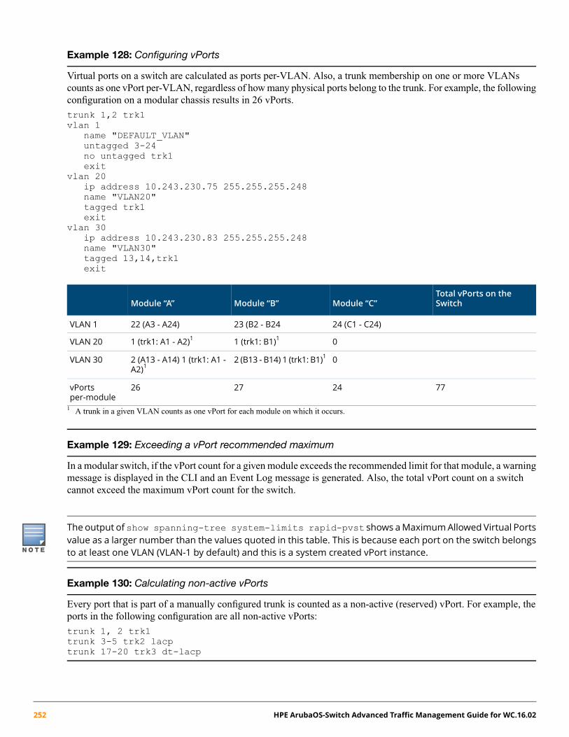
Example 128: Configuring vPorts
Virtual ports on a switch are calculated as ports per-VLAN. Also, a trunk membership on one or more VLANscounts as one vPort per-VLAN, regardless of how many physical ports belong to the trunk. For example, the followingconfiguration on a modular chassis results in 26 vPorts.
trunk 1,2 trk1vlan 1
name "DEFAULT_VLAN"untagged 3-24no untagged trk1exit
vlan 20ip address 10.243.230.75 255.255.255.248name "VLAN20"tagged trk1exit
vlan 30ip address 10.243.230.83 255.255.255.248name "VLAN30"tagged 13,14,trk1exit
Total vPorts on theSwitchModule “C”Module “B”Module “A”
24 (C1 - C24)23 (B2 - B2422 (A3 - A24)VLAN 1
01 (trk1: B1)11 (trk1: A1 - A2)1VLAN 20
02 (B13 - B14) 1 (trk1: B1)12 (A13 - A14) 1 (trk1: A1 -A2)1
VLAN 30
77242726vPortsper-module
1 A trunk in a given VLAN counts as one vPort for each module on which it occurs.
Example 129: Exceeding a vPort recommended maximum
In a modular switch, if the vPort count for a given module exceeds the recommended limit for that module, a warningmessage is displayed in the CLI and an Event Log message is generated. Also, the total vPort count on a switchcannot exceed the maximum vPort count for the switch.
The output of show spanning-tree system-limits rapid-pvst shows aMaximumAllowed Virtual Portsvalue as a larger number than the values quoted in this table. This is because each port on the switch belongsto at least one VLAN (VLAN-1 by default) and this is a system created vPort instance.
Example 130: Calculating non-active vPorts
Every port that is part of a manually configured trunk is counted as a non-active (reserved) vPort. For example, theports in the following configuration are all non-active vPorts:
trunk 1, 2 trk1trunk 3-5 trk2 lacptrunk 17-20 trk3 dt-lacp
252 HPE ArubaOS-Switch Advanced Traffic Management Guide for WC.16.02
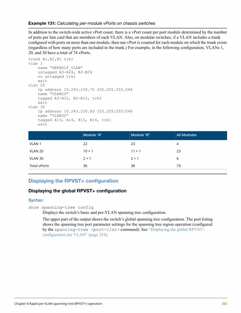
Example 131: Calculating per-module vPorts on chassis switches
In addition to the switch-wide active vPort count, there is a vPort count per port module determined by the numberof ports per line card that are members of each VLAN. Also, on modular switches, if a VLAN includes a trunkconfigured with ports on more than one module, then one vPort is counted for each module on which the trunk exists(regardless of how many ports are included in the trunk.) For example, in the following configuration, VLANs 1,20, and 30 have a total of 74 vPorts.
trunk A1,A2,B1 trk1vlan 1
name “DEFAULT_VLAN”untagged A3-A24, B2-B24no untagged trk1exit
vlan 20ip address 10.243.230.75 255.255.255.248name “VLAN20”tagged A3-A12, B2-B12, trk1exit
vlan 30ip address 10.243.230.83 255.255/255/248name “VLAN30”tagged A13, A14, B13, B14, trk1exit
All ModulesModule “B”Module “A”
42322VLAN 1
2311 + 110 + 1VLAN 20
62 + 12 + 1VLAN 30
743836Total vPorts
Displaying the RPVST+ configuration
Displaying the global RPVST+ configuration
Syntax:
show spanning-tree configDisplays the switch’s basic and per-VLAN spanning tree configuration.
The upper part of the output shows the switch’s global spanning tree configuration. The port listingshows the spanning tree port parameter settings for the spanning tree region operation (configuredby the spanning-tree <port-list> command). See “Displaying the global RPVST+configuration per VLAN” (page 254).
Chapter 8 Rapid per-VLAN spanning tree (RPVST+) operation 253
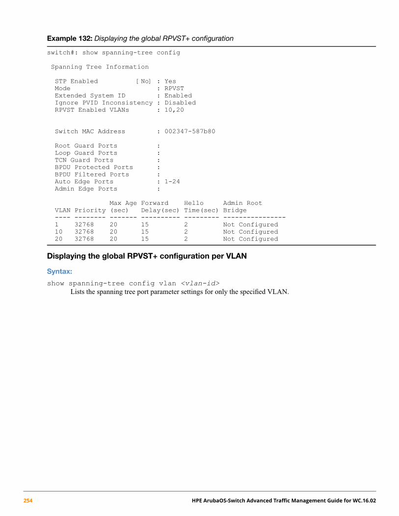
Example 132: Displaying the global RPVST+ configuration
switch#: show spanning-tree config
Spanning Tree Information
STP Enabled [No] : YesMode : RPVSTExtended System ID : EnabledIgnore PVID Inconsistency : DisabledRPVST Enabled VLANs : 10,20
Switch MAC Address : 002347-587b80
Root Guard Ports :Loop Guard Ports :TCN Guard Ports :BPDU Protected Ports :BPDU Filtered Ports :Auto Edge Ports : 1-24Admin Edge Ports :
Max Age Forward Hello Admin RootVLAN Priority (sec) Delay(sec) Time(sec) Bridge---- -------- ------- ---------- --------- ----------------1 32768 20 15 2 Not Configured10 32768 20 15 2 Not Configured20 32768 20 15 2 Not Configured
Displaying the global RPVST+ configuration per VLAN
Syntax:
show spanning-tree config vlan <vlan-id>Lists the spanning tree port parameter settings for only the specified VLAN.
254 HPE ArubaOS-Switch Advanced Traffic Management Guide for WC.16.02

Example 133: Displaying the global RPVST+ configuration per VLAN
switch(config)#: show spanning-tree config vlan 20
Spanning Tree Information
STP Enabled [No] : YesMode : RPVSTExtended System ID : EnabledIgnore PVID Inconsistency : DisabledSwitch MAC Address : 002347-587b80
RPVST Enabled : EnabledVLAN ID : 20Switch Priority : 32768Forward Delay : 15Hello Time : 2Max Age : 20Admin Root Bridge : Not Configured
Path PortPort Type Cost Priority----- ---------- --------- ---------9 100/1000T 20000 12820 100/1000T 200000 12821 100/1000T 20000 128
Displaying the global RPVST+ configuration per port
Syntax:
show spanning-tree [ethernet] <port-list> configLists the spanning tree port parameter settings (global and per VLAN) for only the specified portsand/or trunks. You can list data for a series of ports and port trunks by specifying the first and lastport or trunk of any consecutive series of ports and trunks. For example, to display data for ports 9,11, 12, 21 and trk1, use this command:show spanning-tree 9,11,12,21,trk1 config
Chapter 8 Rapid per-VLAN spanning tree (RPVST+) operation 255
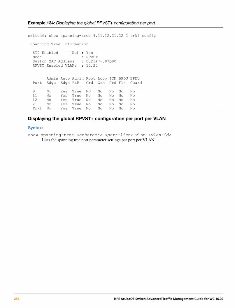
Example 134: Displaying the global RPVST+ configuration per port
switch#: show spanning-tree 9,11,12,21,22 2 trk1 config
Spanning Tree Information
STP Enabled [No] : YesMode : RPVSTSwitch MAC Address : 002347-587b80RPVST Enabled VLANs : 10,20
Admin Auto Admin Root Loop TCN BPDU BPDUPort Edge Edge PtP Grd Grd Grd Flt Guard----- ----- ---- ----- ---- ---- --- ---- -----9 No Yes True No No No No No11 No Yes True No No No No No12 No Yes True No No No No No21 No Yes True No No No No NoTrk1 No Yes True No No No No No
Displaying the global RPVST+ configuration per port per VLAN
Syntax:
show spanning-tree <ethernet> <port-list> vlan <vlan-id>Lists the spanning tree port parameter settings per port per VLAN.
256 HPE ArubaOS-Switch Advanced Traffic Management Guide for WC.16.02

Example 135: Displaying the global RPVST+ configuration per port per VLAN
switch#: show spanning-tree 9 config vlan 10
Spanning Tree Information
STP Enabled [No] : YesMode : RPVSTExtended System ID : EnabledIgnore PVID Inconsistency : DisabledSwitch MAC Address : 002347-587b80
RPVST Enabled : EnabledVLAN ID : 10Switch Priority : 32768Forward Delay : 15Hello Time : 2Max Age : 20Admin Root Bridge : Not Configured
Path Port Admin Auto Admin Root Loop TCN BPDU BPDUPort Cost Priority Edge Edge PtP Grd Grd Grd Flt Guard----- --------- -------- ----- ---- ----- ---- ---- --- ---- -----9 20000 128 No Yes True No No No No No
Troubleshooting an RPVST+ configurationThis section describes the show spanning tree commands you can use to monitor, troubleshoot, and debug theoperation of a per-VLAN spanning tree configuration in your network.
The show spanning-tree commands described in this section, allow you to troubleshoot RPVST+ activity inyour network by focusing on increasingly specific levels of operation. For example, you can display debuginformation for:
• All VLANs
• All ports of one VLAN
• A specific port or several ports used in one VLAN
Displaying the change history of root bridges
Syntax:
show spanning-tree root-history vlan <vlan-id>Displays the last 10 root bridge changes on a specified VLAN configured with RPVST+. Includedare the timestamp and Root Bridge ID recorded at each root bridge change.
Use the show spanning-tree root-history command to view the number and dates of changes in theassignment of a root bridge. Possible intrusion into your VLAN network may occur if an unauthorized externaldevice gains access to a spanning tree by posing as the root device in a topology. To prevent a port connected to thedevice from being selected as the root port in a topology, use the spanning-tree root-guard command.
Chapter 8 Rapid per-VLAN spanning tree (RPVST+) operation 257

Example 136: Displaying the change history of root bridges
switch#: show spanning-tree root-history vlan 20
Status and Counters - RPVST Root Changes History
VLAN ID : 20Root Changes Counter : 53Current Root Bridge ID : 32768:0024a8-d13a40
Root Bridge ID Date Time------------------- ---------- --------32768:0024a8-d13a40 05/04/2012 21:54:11
0:001185-c6e500 05/04/2012 21:54:0732768:0024a8-d13a40 05/04/2012 16:41:11
0:001185-c6e500 05/04/2012 16:41:11
Enabling traps and displaying trap configuration
Syntax:
[no] spanning-tree trap [ errant-bpdu | loop-guard | new-root topology-change[vlan < vid-list | instance [instance-ID] {cstt} | root-guard ]
Enables or disables SNMP traps for errant-BPDU, loop guard, new root, and root guard eventnotifications.errant-bpdu Enables SNMP notification when an errant BPDU is received. Designed for
use with BPDU filtering (see“Configuring BPDU filtering” (page 113)).
loop-guard Enables SNMP notification when a loop guard inconsistency is detected.Designed for use with the Loop Guard option (see “Configuring STP loopguard” (page 240)).
new-root Enables SNMP notification when a new root is elected on any VLAN configuredfor RPVST+ on the switch.
root-guard Enables SNMP notifications when a root-guard inconsistency is detected.
topology-change Enables notifications sent when a topology change occurs.
topology-change-history Shows the spanning tree topology history changes.
Default for all of the above options: Disabled
The no form of the command disables traps on the switch.
Syntax:
show spanning-tree trapsDisplays the current spanning tree trap configuration on the switch.
258 HPE ArubaOS-Switch Advanced Traffic Management Guide for WC.16.02

Example 137: Displaying spanning tree traps in the default configuration
switch#: show spanning-tree traps
Status and Counters - STP Traps Information
Trap Name | Status---------------------- + --------errant-bpdu | Disablednew-root | Disabledroot-guard | Disabledloop-guard | Disabled
Displaying debug counters for all VLAN instances
Syntax:
show spanning-tree debug-countersDisplays the aggregate values of all RPVST+ debug counters that are maintained on a switch. Theseaggregate values are a summary of the information collected from all ports and from all spanningtree instances for all switch ports. Use the displayed diagnostic information to globally monitorRPVST+ operation on a per-switch basis.
Example 138: Displaying debug counters for all VLANs
switch#: show spanning-tree debug-counters
Status and Counters - RPVST Debug Counters Information
Aggregated ValueCounter Name Collected from VLANs------------------------------ -------------------------Invalid BPDUs 0Errant BPDUs 0Looped-back BPDUs 0Starved BPDUs 18Exceeded Max Age BPDUs 3Topology Changes Detected 9Topology Changes Tx 9Topology Changes Rx 4Topology Change ACKs Tx 0Topology Change ACKs Rx 6TCN BPDUs Tx 4TCN BPDUs Rx 0CFG BPDUs Tx 0CFG BPDUs Rx 0RST BPDUs Tx 0RST BPDUs Rx 0RPVST BPDUs Tx 1881RPVST BPDUs Rx 2617
See “Field descriptions for RPVST+ debug command output” (page 261).
Chapter 8 Rapid per-VLAN spanning tree (RPVST+) operation 259
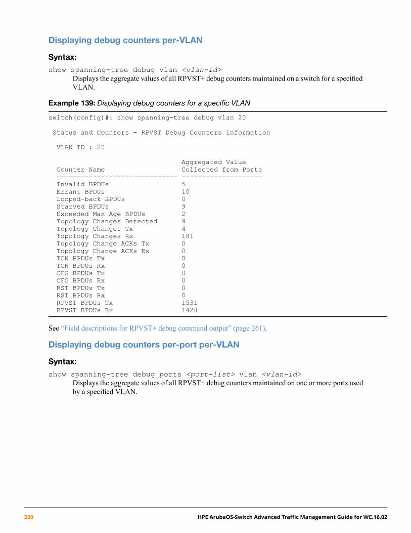
Displaying debug counters per-VLAN
Syntax:
show spanning-tree debug vlan <vlan-id>Displays the aggregate values of all RPVST+ debug counters maintained on a switch for a specifiedVLAN.
Example 139: Displaying debug counters for a specific VLAN
switch(config)#: show spanning-tree debug vlan 20
Status and Counters - RPVST Debug Counters Information
VLAN ID : 20
Aggregated ValueCounter Name Collected from Ports------------------------------ --------------------Invalid BPDUs 5Errant BPDUs 10Looped-back BPDUs 0Starved BPDUs 9Exceeded Max Age BPDUs 2Topology Changes Detected 9Topology Changes Tx 4Topology Changes Rx 181Topology Change ACKs Tx 0Topology Change ACKs Rx 0TCN BPDUs Tx 0TCN BPDUs Rx 0CFG BPDUs Tx 0CFG BPDUs Rx 0RST BPDUs Tx 0RST BPDUs Rx 0RPVST BPDUs Tx 1531RPVST BPDUs Rx 1428
See “Field descriptions for RPVST+ debug command output” (page 261).
Displaying debug counters per-port per-VLAN
Syntax:
show spanning-tree debug ports <port-list> vlan <vlan-id>Displays the aggregate values of all RPVST+ debug counters maintained on one or more ports usedby a specified VLAN.
260 HPE ArubaOS-Switch Advanced Traffic Management Guide for WC.16.02
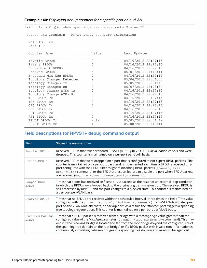
Example 140: Displaying debug counters for a specific port on a VLAN
Switch_A(config)#: show spanning-tree debug ports 9 vlan 20
Status and Counters - RPVST Debug Counters Information
VLAN ID : 20Port : 9
Counter Name Value Last Updated------------------------------ --------------- --------------------Invalid BPDUs 0 04/16/2012 22:27:15Errant BPDUs 0 04/16/2012 22:27:15Looped-back BPDUs 0 04/16/2012 22:27:15Starved BPDUs 5 05/01/2012 21:48:11Exceeded Max Age BPDUs 0 04/16/2012 22:27:15Topology Changes Detected 9 05/04/2012 21:54:05Topology Changes Tx 5 05/05/2012 22:04:49Topology Changes Rx 2 05/07/2012 18:08:34Topology Change ACKs Tx 0 04/16/2012 22:27:15Topology Change ACKs Rx 0 04/16/2012 22:27:15TCN BPDUs Tx 0 04/16/2012 22:27:15TCN BPDUs Rx 0 04/16/2012 22:27:15CFG BPDUs Tx 0 04/16/2012 22:27:15CFG BPDUs Rx 0 04/16/2012 22:27:15RST BPDUs Tx 0 04/16/2012 22:27:15RST BPDUs Rx 0 04/16/2012 22:27:15RPVST BPDUs Tx 7812 05/05/2012 22:04:49RPVST BPDUs Rx 1065 05/08/2012 19:43:11
Field descriptions for RPVST+ debug command output
Shows the number of —Field
Received BPDUs that failed standard RPVST+ (802.1Q-REV/D5.0 14.4) validation checks and weredropped. This counter is maintained on a per-port per-VLAN basis.
Invalid BPDUs
Received BPDUs that were dropped on a port that is configured to not expect BPDU packets. Thiscounter is maintained on a per-port basis and is incremented each time a BPDU is received on a
Errant BPDUs
port configured with the BPDU filter to ignore incoming BPDU packets (spanning-treebpdu-filter command) or the BPDU protection feature to disable the port when BPDU packetsare received (spanning-tree bpdu-protection command).
Times that a port has received self-sent BPDU packets as the result of an external loop conditionin which the BPDUs were looped back to the originating transmission port. The received BPDU is
Looped-backBPDUs
still processed by RPVST+ and the port changes to a blocked state. This counter is maintained ona per-port per-VLAN basis.
Times that no BPDUs are received within the scheduled interval (three times the Hello Time valueconfiguredwith thespanning-tree vlan hello-time command) fromaVLAN-designatedpeer
Starved BPDUs
port on the VLAN root, alternate, or backup port. As a result, the “starved” port triggers a spanningtree topology regeneration. This counter is maintained on a per-port per-VLAN basis.
Times that a BPDU packet is received from a bridge with a Message Age value greater than theconfigured value of theMax Age parameter (spanning-tree maximum age command). Thismay
Exceeded Max AgeBPDUs
occur if the receiving bridge is located too far from the root bridge (beyond the configured size ofthe spanning tree domain on the root bridge) or if a BPDU packet with invalid root information iscontinuously circulating between bridges in a spanning tree domain and needs to be aged out.
Chapter 8 Rapid per-VLAN spanning tree (RPVST+) operation 261

Shows the number of —Field
Times that a Topology Change event is detected by the port on a given VLAN and the port triggersa topology change propagation throughout the network. A Topology Change event occurs when anon-edge port enters forwarding state. This counter is maintained on a per-VLAN per-port basis.
Topology ChangesDetected
Times that Topology Change information is propagated (sent out) through the port to the rest ofthe network. For a VLAN port running PVST (non-rapid), the counter is the number of times that a
Topology ChangesTx
CFG or RST BPDU with the TC flag set is transmitted out of the port. This counter is maintained ona per-VLAN per-port basis.
Times that Topology Change information is received from the peer port. For a VLAN port runningPVST (non-rapid), the counter is the number of times that a CFG or RST BPDU with the TC flag setis received. This counter is maintained on a per-port per-VLAN basis.
Topology ChangesRx
Times that the Topology Change acknowledgement is transmitted through the port (number ofCFG or RST BPDUs transmitted with the Topology Change Acknowledge flag set). This counter ismaintained on a per-port per-VLAN basis.
Topology ChangeACKs Tx
Times that the Topology Change acknowledgement is received on the port (number of CFG or RSTBPDUs received with the Topology Change Acknowledge flag set). This counter is maintained on aper-VLAN basis.
Topology ChangeACKs Rx
Topology Change Notification BPDUs that are transmitted through the port. This counter ismaintained on a per-port basis.
TCN BPDUs Tx
Topology Change Notification BPDUs that are received on the port. This counter is maintained ona per-port per-VLAN basis.
TCN BPDUs Rx
802.1D configuration BPDUs that are transmitted through the port. This counter is maintained ona per-port per-VLAN basis.
CFG BPDUs Tx
802.1D configuration BPDUs that are received on the port. This counter maintained on a per-portper-VLAN basis.
CFG BPDUs Rx
802.1w RST BPDUs that are transmitted through the port. This counter is maintained on a per-portper-VLAN basis.
RST BPDUs Tx
802.1wRST BPDUs that are received on the port. This counter ismaintained on a per-port per-VLANbasis.
RST BPDUs Rx
RPVST+ event log messages
Log messageEvent
Spanning tree Protocol enabled/disabled on vlan <vlan-id>STP enabled/disabled on a VLAN
VLAN <vlan-id> starved for a BPDU on port <port number> from<bridge name>
Switch does not receive BPDUs frompeeron a particular VLAN and port
Blocking port-name on vlan <vlan-id>.Switch received BPDU with inconsistentVLAN
Unblocking port-name on vlan <vlan-id>Port consistencyrestored..
Inconsistency is restored
VLAN <vlan-id>root changed from <bridgepriorty:mac> to <bridgepriority:mac>
Root port is changed on a VLAN
Received SSTP BPDU with bad TLV on <port-number> <vlan-id>Switch received a BPDU with invalid TLV
The number of vlan-port instances exceeded the recommendedlimit of <num>
The number of vlan-port instancesexceeds the recommended limit
262 HPE ArubaOS-Switch Advanced Traffic Management Guide for WC.16.02
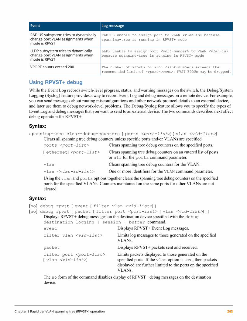
Log messageEvent
RADIUS unable to assign port to VLAN <vlan-id> becausespanning-tree is running in RPVST+ mode
RADIUS subsystem tries to dynamicallychange port VLAN assignments whenmode is RPVST
LLDP unable to assign port <port-number> to VLAN <vlan-id>because spanning-tree is running in RPVST+ mode
LLDP subsystem tries to dynamicallychange port VLAN assignments whenmode is RPVST
The number of vPorts on slot <slot-number> exceeds therecommended limit of <vport-count>. PVST BPDUs may be dropped.
VPORT counts exceed 200
Using RPVST+ debugWhile the Event Log records switch-level progress, status, and warning messages on the switch, the Debug/SystemLogging (Syslog) feature provides a way to record Event Log and debug messages on a remote device. For example,you can send messages about routing misconfigurations and other network protocol details to an external device,and later use them to debug network-level problems. The Debug/Syslog feature allows you to specify the types ofEvent Log and debug messages that you want to send to an external device. The two commands described next affectdebug operation for RPVST+.
Syntax:
spanning-tree clear-debug-counters [ports <port-list>][vlan <vid-list>]Clears all spanning tree debug counters unless specific ports and/or VLANs are specified.ports <port-list> Clears spanning tree debug counters on the specified ports.
[ethernet]<port-list> Clears spanning tree debug counters on an entered list of postsor all for the ports command parameter.
vlan Clears spanning tree debug counters for the VLAN.
vlan <vlan-id-list> One or more identifiers for the VLAN command parameter.
Using the vlan and ports options together clears the spanning tree debug counters on the specifiedports for the specified VLANs. Counters maintained on the same ports for other VLANs are notcleared.
Syntax:
[no] debug rpvst [event [filter vlan <vid-list>]][no] debug rpvst [packet [filter port <port-list> [vlan <vid-list>]]]
Displays RPVST+ debug messages on the destination device specified with the debugdestination logging | session | buffer command.event Displays RPVST+ Event Log messages.
filter vlan <vid-list> Limits log messages to those generated on the specifiedVLANs.
packet Displays RPVST+ packets sent and received.
filter port <port-list>[vlan <vid-list>]
Limits packets displayed to those generated on thespecified ports. If the vlan option is used, then packetsdisplayed are further limited to the ports on the specifiedVLANs.
The no form of the command disables display of RPVST+ debug messages on the destinationdevice.
Chapter 8 Rapid per-VLAN spanning tree (RPVST+) operation 263
About RPVST+
Comparing spanning tree optionsWithout spanning tree, having more than one active path between a pair of nodes causes loops in the network, whichcan result in duplication of messages, leading to a “broadcast storm” that can bring down the network.
The 802.1D spanning tree protocol operates without regard to a network's VLAN configuration, and maintains onecommon spanning tree throughout a bridged network. This protocol maps one loop-free, logical topology on a givenphysical topology. This results in the least optimal link utilization and longest convergence times.
The 802.1s multiple spanning tree protocol (MSTP) uses multiple spanning tree instances with separate forwardingtopologies. Each instance is composed of one or more VLANs, which significantly improves network link utilizationand the speed of reconvergence after a failure in the network’s physical topology. However, MSTP requires moreconfiguration overhead and is more susceptible to dropped traffic due to misconfiguration.
Rapid spanning tree protocol (RSTP) requires less configuration overhead, provides faster convergence onpoint-to-point links, and speedier failure recovery with predetermined, alternate paths. The switches covered by thisguide, use the IEEE Rapid Per-VLAN spanning tree Protocol (RPVST) standard. RPVST was introduced as anenhancement to Rapid spanning tree Protocol (RSTP) to improve the link utilization issue and require less configurationoverhead. Basically, RPVST+ is RSTP operating per-VLAN in a single layer 2 domain. VLAN tagging is appliedto the ports in a multi-VLAN network to enable blocking of redundant links in one VLAN while allowing forwardingover the same links for non-redundant use by another VLAN. Each RPVST+ tree can have a different root switchand therefore can span through different links. Since different VLAN traffic can take different active paths frommultiple possible topologies, overall network utilization increases.
Another major advantage of RPVST+ is that it localizes topology change propagation to individual VLANs. Sincethere is a separate spanning tree for each VLAN, topology changes affecting a particular VLAN are propagated onlyinside that VLAN. The switch flushes the MAC addresses learned only on the affected VLAN and other VLANtraffic is not disturbed. This minimizes the network flooding caused by the spanning tree topology changes. This isa significant improvement in the case of a large, flat, layer 2 network. In a network having a large number ofper-VLAN spanning tree instances, RPVST+ can cause an increased load on the switch's CPU.
Understanding how RPVST+ operatesRPVST+ applies one RSTP tree per-VLAN. Each of these RSTP trees can have a different root switch and span thenetwork through shared or different links. As shown in Figure 42 (page 265)since the active paths for traffic ondifferent VLANs can use the same for different links, multiple topologies are possible, and overall network utilizationincreases.
264 HPE ArubaOS-Switch Advanced Traffic Management Guide for WC.16.02
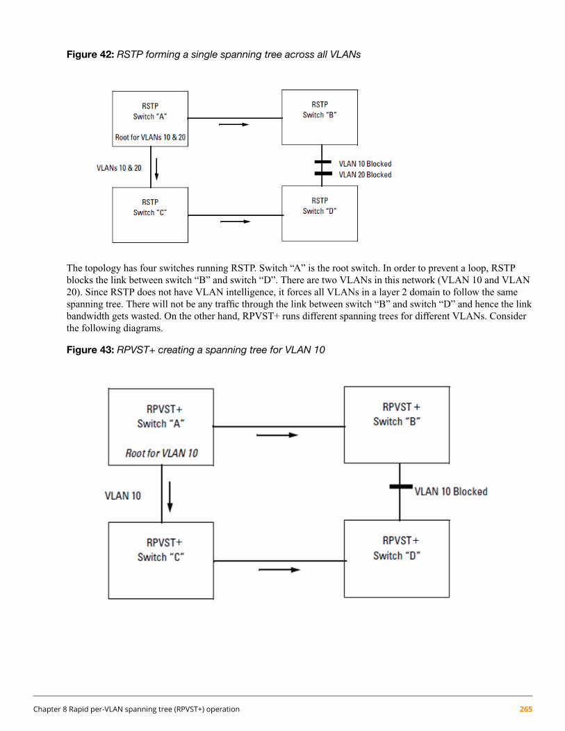
Figure 42: RSTP forming a single spanning tree across all VLANs
The topology has four switches running RSTP. Switch “A” is the root switch. In order to prevent a loop, RSTPblocks the link between switch “B” and switch “D”. There are two VLANs in this network (VLAN 10 and VLAN20). Since RSTP does not have VLAN intelligence, it forces all VLANs in a layer 2 domain to follow the samespanning tree. There will not be any traffic through the link between switch “B” and switch “D” and hence the linkbandwidth gets wasted. On the other hand, RPVST+ runs different spanning trees for different VLANs. Considerthe following diagrams.
Figure 43: RPVST+ creating a spanning tree for VLAN 10
Chapter 8 Rapid per-VLAN spanning tree (RPVST+) operation 265

Figure 44: RPVST+ creating a spanning tree for VLAN 20
The two topologies above are the same as the first topology, but now the switches run RPVST+ and can span differenttrees for different VLANs. Switch “A” is the root switch for the VLAN 10 spanning tree and switch “D” is the rootswitch for the VLAN 20 spanning tree. The link between switch “B” and switch “D” is only blocked for VLAN 10traffic but VLAN 20 traffic goes through that link. Similarly the link between switch “A” and switch “C” is blockedonly for VLAN 20 traffic but VLAN 10 traffic goes through that link. Here, traffic passes through all the availablelinks, and network availability and bandwidth utilization increase.
Another major advantage of RPVST+ is that it localizes topology change propagation. Since there is a separatespanning tree for each VLAN, topology changes affecting a particular VLAN are propagated only inside that VLAN.The switch flushes the MAC addresses learned only on the affected VLAN, the traffic on other VLANs is notdisturbed. This minimizes the network flooding due to spanning tree topology changes. This is a significantimprovement in the case of a large, flat, layer 2 network.
The following figure shows a further example of shared links and redundant path-blocking in a network runningRPVST+.
266 HPE ArubaOS-Switch Advanced Traffic Management Guide for WC.16.02
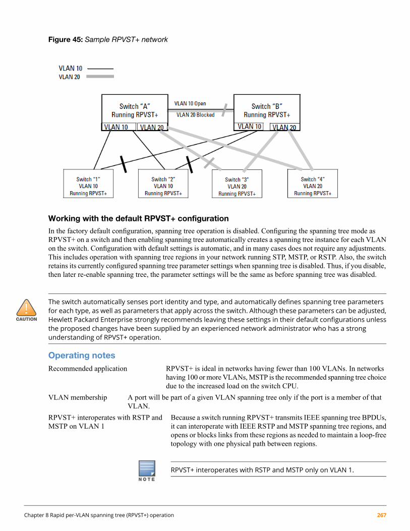
Figure 45: Sample RPVST+ network
Working with the default RPVST+ configuration
In the factory default configuration, spanning tree operation is disabled. Configuring the spanning tree mode asRPVST+ on a switch and then enabling spanning tree automatically creates a spanning tree instance for each VLANon the switch. Configuration with default settings is automatic, and in many cases does not require any adjustments.This includes operation with spanning tree regions in your network running STP, MSTP, or RSTP. Also, the switchretains its currently configured spanning tree parameter settings when spanning tree is disabled. Thus, if you disable,then later re-enable spanning tree, the parameter settings will be the same as before spanning tree was disabled.
The switch automatically senses port identity and type, and automatically defines spanning tree parametersfor each type, as well as parameters that apply across the switch. Although these parameters can be adjusted,Hewlett Packard Enterprise strongly recommends leaving these settings in their default configurations unlessthe proposed changes have been supplied by an experienced network administrator who has a strongunderstanding of RPVST+ operation.
Operating notesRecommended application RPVST+ is ideal in networks having fewer than 100 VLANs. In networks
having 100 or more VLANs, MSTP is the recommended spanning tree choicedue to the increased load on the switch CPU.
VLAN membership A port will be part of a given VLAN spanning tree only if the port is a member of thatVLAN.
RPVST+ interoperates with RSTP andMSTP on VLAN 1
Because a switch running RPVST+ transmits IEEE spanning tree BPDUs,it can interoperate with IEEE RSTP and MSTP spanning tree regions, andopens or blocks links from these regions as needed to maintain a loop-freetopology with one physical path between regions.
RPVST+ interoperates with RSTP and MSTP only on VLAN 1.
Chapter 8 Rapid per-VLAN spanning tree (RPVST+) operation 267

Single spanning tree applications One spanning tree variant can be run on the switch at any given time. Ona switch running RPVST+, MSTP cannot be enabled. However, anyMSTP-specific configuration settings in the startup configuration file willbe maintained.
Exclusions
The following features cannot run concurrently with RPVST+:
• Features that dynamically assign ports to VLANs:
GVRP◦◦ RADIUS-based VLAN assignments (802.1X, WebAuth, MKAC auth)
◦ Auth-VID/UnAuth-VID configuration on interfaces
◦ MAC-Based VLANs
◦ LLDP Radio Port VLAN
• Switch Meshing
• Protocol VLANs
• Distributed Trunking
• Filter Multicast in rapid-PVST mode (The multicast MAC address value cannot be set to thePVST MAC address 01:00:0c:cc:cc:cd.)
GVRP Spanning tree mode cannot be set to RPVST+ when GVRP is enabled, and GVRP cannot be enabled whenRPVST+ is enabled.
RPVST+ operating limits Virtual ports (vPorts) on a switch are determined by the number of physicalports on the switch, plus other factors. Exceeding the recommended numberof vPorts can cause dropped BPDUs. For more information, see “DisplayingRPVST+ VLAN and vPort system limits” (page 250).
Allowing traffic on per-VLAN ID(PVID) mismatched links
The switch generates an Event Log message for a VID mismatch on anactive RPVST+ VLAN only if ignore-pvid-inconsistency isdisabled (the default).
If ignore-pvid-inconsistency is enabled on multiple switchesconnected by hubs, there could be more than two VLANs involved inPVID mismatches that will be ignored by RPVST+.
If there is an actual misconfiguration of port VLAN memberships in anetwork, then enabling ignore-pvid-inconsistency prevents RPVST+ fromdetecting the problem. This could result in packet duplication in the networkbecause RPVST+ would not converge correctly.
268 HPE ArubaOS-Switch Advanced Traffic Management Guide for WC.16.02

Chapter 9
VXLAN
OverviewVirtual Extensible LAN(VXLAN) is a network virtualization technology that allows the extension of L2 networksover L3 UDP tunnels.
Example 141: VXLAN tunnel
The 192.168.10.X/24 subnet is being tunneled through the 30.10.10.X/24 network.
Figure 46: VXLAN tunnel
L2 Forwarding in VXLANVXLAN learns unicast source MAC addresses similar to hosts off of physical ports. When a packet is de-encapsulatedfrom a VXLAN tunnel, the source MAC is checked against the MAC table and bound to the tunnel interface indexor if it is not present, it is learned. If the unicast source is in the MAC table but on a different port or tunnel to it, itis considered a move. The MAC table is used as the destination match to send traffic to a remote tunnel partner.Any unknown destination addresses are forwarded to all VTEP partners, configured with a common Virtual NetworkIdentifier (VNI).
Broadcast addresses are handled similar to unknown destination addresses and flooded to all tunnels with mappedand configured VNI. Floods are copied to each unicast VTEP tunnel. Multicast addresses are not filtered, they aretreated like a flood when going to multiple tunnel destinations.
Fully Meshed NetworkIn a fully meshed VXLAN network, every VTEP is configured with a tunnel to every other VTEP running the sameVNI. A fully meshed VXLAN network allows for any overlay network to reach any other part of the network forlocal L2 to L2 traffic. This is necessary when client to client traffic is needed amongst roaming clients with the samesubnet.
Chapter 9 VXLAN 269

Example 142: Fully meshed network
Every VTEP needs 6 Tunnel connections to reach every other VTEP in the mesh network.
Figure 47: Fully meshed network
Hub Spoke NetworkThe configuration is simple for all VTEPs except for the gateway. Each outer VTEP needs to have a tunnel plumbedback to the VXLAN VTEP Gateway for VTEPs 1-6. The gateway however needs a tunnel to each of the VTEPsconfigured on the edge.
270 HPE ArubaOS-Switch Advanced Traffic Management Guide for WC.16.02

Example 143: Hub spoke network
In the following Hub spoke model, traffic only flows from the edge VTEPs back to the VXLAN gateway.
Figure 48: Hub spoke network
RestrictionsThe following is a limitation of VXLAN:
• For any given L2 virtual network, only one VTEP can be present for each edge L2 LAN.
VXLAN — Feature interaction table
VXLAN impactFeature
VXLAN tunnel interfaces would be (implicitly) TRUSTEDinterfaces with no MAC/IP verification on ARP PKTsingressing tunnels.
ARP protect
ARP protectionwill be enforced on other untrusted portsof the overlay VLAN if ARP protection is enabled for thatVLAN.
Chapter 9 VXLAN 271

VXLAN impactFeature
A VLAN that has a virtual IP subnet and a VNIconfigured for it is referred to as an overlay VLANin here.
CDP only runs on physical links. VXLANs are not able toparticipate in CDP.
CDP
A gateway device is able to function as a DHCP Relayagent and support transferring DHCP PKTs between thefollowingdependingonwhere theDHCP server is housed:
DHCP (v4/v6) relay
• An overlay subnet and an underlay subnet.
• An overlay subnet and another overlay subnet.
VXLAN tunnel interfaces would be (implicitly) TRUSTEDwith noMAC/IP/Port verification onDHCPPKTs ingressingtunnels.
DHCP snooping
filter • ConnectionRate (Virus Throttling) – Cannot be enabledon a VXLAN tunnel interface.
• Multicast – Tunnel interface cannot be part of the dropfilter. PKTs coming in on a tunnel interface will honordrop filter if configured for the multicast address.
• Protocol – Similar to Multicast filters.
• Source Port - Tunnel interface cannot be part of thedrop filter. A tunnel interface cannot have a sourceport filter configured for it.
No support for IGMP SNOOPing and Multicast pruningon VXLAN tunnel interfaces.
IGMP snooping
If a device is an IGMP querier on an overlay VLAN, theIGMP queries sourced by the device will be sent over theVTEP fabric to the other nodes as well.IGMP blocked and forward configuration cannot beapplied to VXLAN interfaces.
Not applicable to VXLAN tunnel interfaces.IGNOREuntagged-MAC
Not supported on VXLAN tunnel interfaces.Link-Keepalive(UDLD)
LLDP not supported on tunnel interfaces.LLDP
Traffic ingressing a network port with source MAC thatis configured as lockout-MAC will not be tunneled.
Lockout-MAC
Traffic ingressing a tunnel interface (i.e. payload) with asource MAC that is configured as lockout-MAC on thedevice will be dropped upon DECAP.
Not supported on VXLAN tunnel interfacesLoop Protect
272 HPE ArubaOS-Switch Advanced Traffic Management Guide for WC.16.02

VXLAN impactFeature
This Mac-Trap, when configured on an interface, sendsout a trap when:
MAC-TRAPMAC-Count TRAP
• MAC addresses are learned or aged-out on aninterface.
• The number of MAC addresses on a port exceeds acertain threshold.
MAC-Count TRAPs are not supported on VXLAN tunnels.
Cannot monitor a VXLAN tunnel interface.<Interface> Monitor
OpenFlow • OpenFLow sees VXLAN tunnels as logical interfacesand can program outport rules for tunnels.
• OpenFlow cannot program in_port match rules onVXLAN tunnel interfaces (similar to SI).
• OpenFlow lookups will be bypassed for packetsingressing VXLAN tunnels.
Not supported on VXLAN tunnel interface.Port Security
Mutually exclusive.QinQ
QoS Encap WhenQoS rules are configured, trafficmatchingQoS rules and will be prioritized and tunnelledinto the underlay.
Source VLANSource Port
The VLAN priority and DSCP is mapped to theouter header.
UDPTCPdevice
Decap Traffic entering a tunnel (i.e. payload) andmatching QoS rules will be prioritized upondecapsulation and forwardedout appropriately.
protocol
QOS remark policy(PCP/DSCP)
Encap Traffic matching QoS remark rules will havetheir DSCP remarked and re-prioritized beforebeing tunneled into the underlay.
Decap Traffic coming in on a tunnel (i.e. payload) andmatching QoS remark rules (VLAN based) willbe remarked and re-prioritized upondecapsulation and forwardedout appropriately.
QoS rate-limit policyInterface rate-limit
Encap If a rate-limit policy (port/VLANbased) is appliedto traffic destined to a tunnel interface, it willbe enforced before the traffic is encapsulated.
Decap If a rate-limit policy (VLAN based) is applied to(payload) traffic coming in on a tunnel interface,it will be enforced upon ingress on the loopbackport (after decapsulation).Not supported on VXLAN interfaces.
Cannot configure SFLOW (sampling/polling) on tunnelinterfaces and loopback ports. If a packet destined to a
SFLOW
tunnel has been sampled, the outport field in the SFLOWheader will be the tunnel resolved uplink port.
Cannot be configured on tunnel interfaces.Smart-LinkHowever Smart-Link can be used to achieve VTEPredundancy. To ensure that downlink traffic is not
Chapter 9 VXLAN 273

VXLAN impactFeature
disrupted when a VTEP goes down and the downlinkswitch’s Slave Port becomes Active, Smart-Link flushmessages will be allowed to traverse the L3 fabric and itwill wipe out MAC table entries on tunnel interfaces forthe protected VLANs. It will also clear the ARP entriespointing to Tunnel entries on the VTEPs. Per-portrecv-control-vlan restriction is not applicable to Flushpackets received on Tunnel Interfaces as they are trusted,any filtering can always be done on external facing ports.
Does not run on tunnel interfaces and loopback ports.This implies that STP cannot detect loops if any among
STP
switches that are connected via VXLAN tunnels and alsodirectly connected among them.It is important that only one device as the VTEP for a VLANin a network where multiple devices can function asVTEPs for the same VLAN.STP Topology Change message does not have to flushMAC addresses learned on tunnel interfaces as a TC onone segment does not impact theMAC learns of anothersegment.When a device that is STP disabled receives BPDUs, itfloods to all ports of the VLAN. This can result in BPDUsbeing tunneled to the remote side as well. The loopbackport of the remote end will quench the packet and notprocess it.
Not supported on VXLAN tunnel interfaces.Static MAC
Not supported on VXLAN tunnel interfaces.UFD
Not supported on VXLAN tunnels and loopback ports(stolen and internal).
<Interface> IPv4/v6ACLs
Not configurable on VXLAN tunnel and loopbackinterfaces (stolen and internal).
<Interface> IPSource-Lockdown
Not configurable on VXLAN tunnel interface.<Interface>admin-status
IP source binding entries cannot be configured on VXLANtunnel interfaces and loopback ports (stolen/internal).
IP Source Binding
Cannot be enabled on overlay VLANs. BGP is notsupported on WC.16.02.
<VLAN> RIP, OSPF,BGP
Cannot be enabled on overlay VLANs.<VLAN> IRDP
Cannot be enabled on overlay VLANs.<VLAN> IGMP(Router)
Cannot be enabled on overlay VLANs.<VLAN> IGMP Proxy
Supported on overlay VLANs.<VLAN> UDPBroadcast Forwarder
Not supported on tunnel and loopback interfaces(stolen/internal).
<Interface> QoS
Supported. Can route traffic into a tunnel and route trafficcoming out of a tunnel.
IPv4 unicast Routing
274 HPE ArubaOS-Switch Advanced Traffic Management Guide for WC.16.02

VXLAN impactFeature
Not supported.IPv6 unicast Routing
Not supported as overlays are IPv4 only.<VLAN> MLD
Not supported as overlays are IPv4 only.<VLAN> NDNot supported as overlays are IPv4 only.<VLAN> RA
Not supported as overlays are IPv4 only<VLAN> IPv6
Cannot be enabled on overlay VLANs.<VLAN> OSPF3
OpenFlow interactionThe OpenFlow features supported on VXLAN tunnel interfaces are listed in the following table. For more informationabout OpenFlow, see the OpenFlow Administrators Guide.
IS-NOTIS
Cannot addmultiple VXLAN tunnel interfacesas part of multi-port action.
OpenFlow agent on the switch willcommunicate VXLAN tunnel virtualport add/remove notifications to thecontroller.
Cannot group VXLAN tunnels and physicalports as part of multi-port action.
Tunnel virtual port up/downnotificationswill be communicated tothe controller.
Cannot group outport “Tunnel” action withoutport “Normal” or outport“SendToController” actions.
Tunnel virtual port counters (TX/RXpackets) will be supported viaOpenFlow multipart message.
Cannot group outport “Tunnel” action withStrip VLAN,Modify VLAN,ModifyMAC actions.
In OpenFlow virtualized mode, onlyOpenFlow version1.3 instances of theOverlay VLAN will advertise VXLANvirtual ports to the controller.
Cannot support re-directing PKTs to VXLANtunnels on an OpenFlow v1.0 instance.
The VNI corresponding to theOverlayVLAN needs to be associated with the
Tunnels will only be supported on OpenFlowv1.3 instances.
VXLAN tunnel for it to be advertisedas a member interface of thatinstance.
The solution does not support OpenFlowlookup on frames coming in on a VXLAN
In OpenFlow aggregate mode, anOpenFlow rule that has a VXLAN
tunnel. These PKTs will be forwarded astunnel as an outport will be allowed“normal” using the switch L2/L3 forwardingtable entries.
only if the in_vlan is an overlay VLANand its VNI is associated with theVXLAN tunnel.
When tunnel interfaces are deleted by theadministrator and there are OpenFlow rules
OpenFlow meters can be attached torules that point to tunnels as output
that are pointing to those tunnels, the switchports and metering action will workas designed. will not automatically remove flows associated
with the tunnel ports. The controller has todelete those flows explicitly.
The send-to-tunnel outport action would besupported only on the Policy Engine (TCAM)
VXLAN tunnel interfaces will be partof an OpenFlow VLAN FLOOD action.
Chapter 9 VXLAN 275
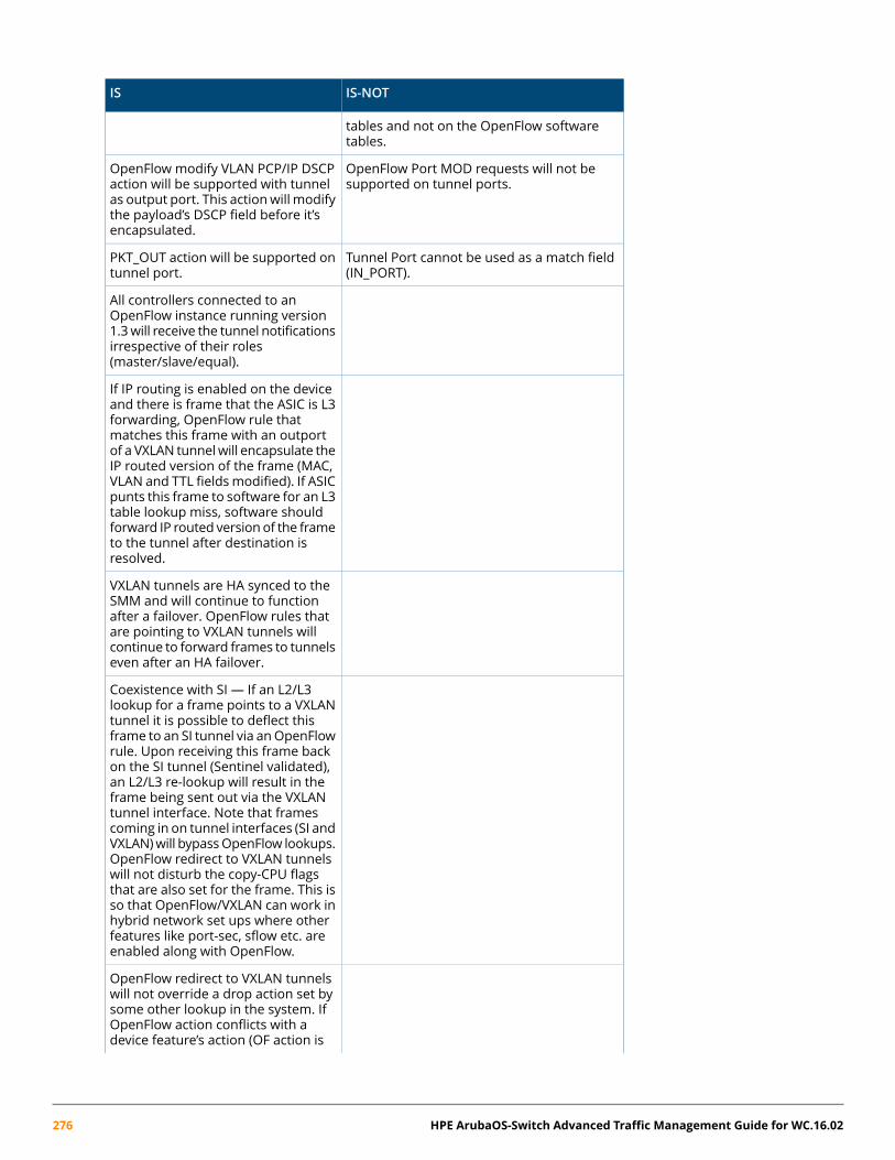
IS-NOTIS
tables and not on the OpenFlow softwaretables.
OpenFlow Port MOD requests will not besupported on tunnel ports.
OpenFlow modify VLAN PCP/IP DSCPaction will be supported with tunnelas output port. This actionwill modifythe payload’s DSCP field before it’sencapsulated.
Tunnel Port cannot be used as a match field(IN_PORT).
PKT_OUT action will be supported ontunnel port.
All controllers connected to anOpenFlow instance running version1.3will receive the tunnel notificationsirrespective of their roles(master/slave/equal).
If IP routing is enabled on the deviceand there is frame that the ASIC is L3forwarding, OpenFlow rule thatmatches this frame with an outportof a VXLAN tunnelwill encapsulate theIP routed version of the frame (MAC,VLAN and TTL fieldsmodified). If ASICpunts this frame to software for an L3table lookup miss, software shouldforward IP routed version of the frameto the tunnel after destination isresolved.
VXLAN tunnels are HA synced to theSMM and will continue to functionafter a failover. OpenFlow rules thatare pointing to VXLAN tunnels willcontinue to forward frames to tunnelseven after an HA failover.
Coexistence with SI — If an L2/L3lookup for a frame points to a VXLANtunnel it is possible to deflect thisframe to an SI tunnel via anOpenFlowrule. Upon receiving this frame backon the SI tunnel (Sentinel validated),an L2/L3 re-lookup will result in theframe being sent out via the VXLANtunnel interface. Note that framescoming in on tunnel interfaces (SI andVXLAN)will bypassOpenFlow lookups.OpenFlow redirect to VXLAN tunnelswill not disturb the copy-CPU flagsthat are also set for the frame. This isso that OpenFlow/VXLAN can work inhybrid network set ups where otherfeatures like port-sec, sflow etc. areenabled along with OpenFlow.
OpenFlow redirect to VXLAN tunnelswill not override a drop action set bysome other lookup in the system. IfOpenFlow action conflicts with adevice feature’s action (OF action is
276 HPE ArubaOS-Switch Advanced Traffic Management Guide for WC.16.02
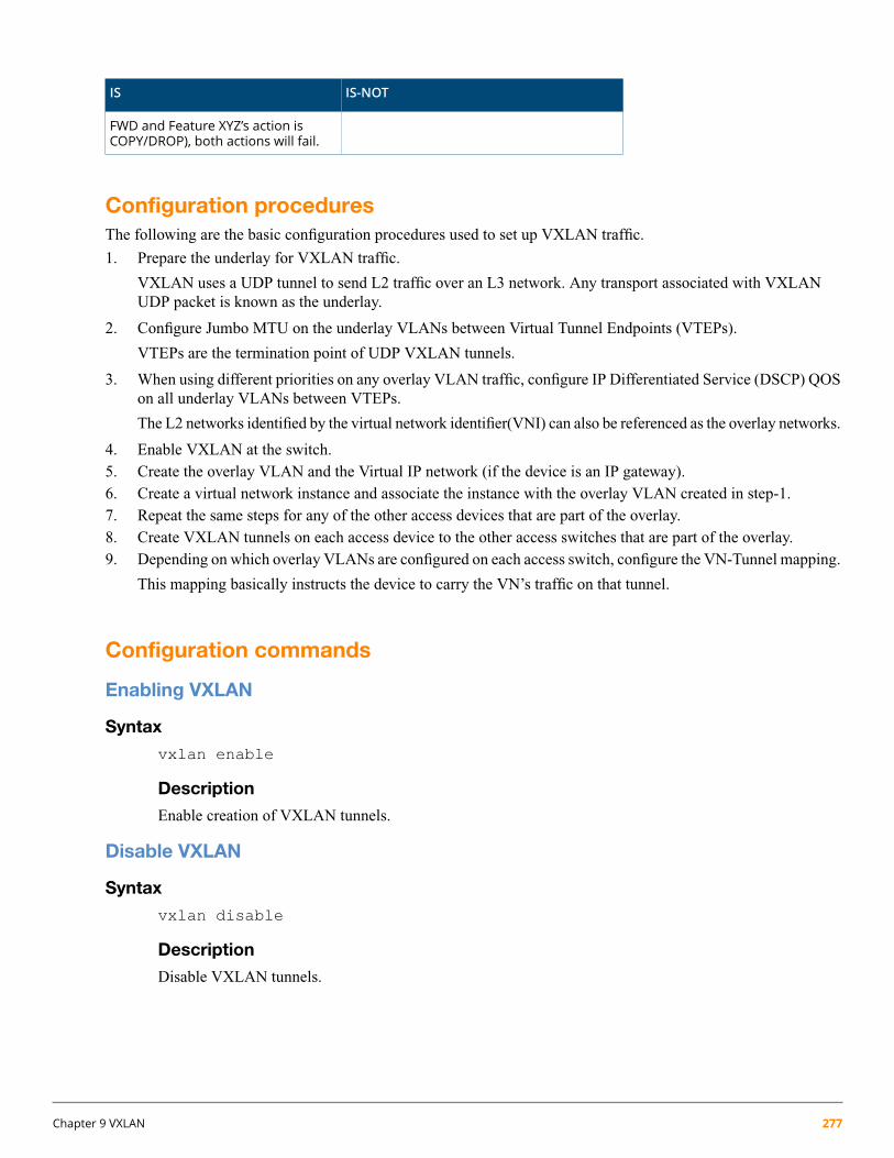
IS-NOTIS
FWD and Feature XYZ’s action isCOPY/DROP), both actions will fail.
Configuration proceduresThe following are the basic configuration procedures used to set up VXLAN traffic.
1. Prepare the underlay for VXLAN traffic.
VXLAN uses a UDP tunnel to send L2 traffic over an L3 network. Any transport associated with VXLANUDP packet is known as the underlay.
2. Configure Jumbo MTU on the underlay VLANs between Virtual Tunnel Endpoints (VTEPs).
VTEPs are the termination point of UDP VXLAN tunnels.
3. When using different priorities on any overlay VLAN traffic, configure IP Differentiated Service (DSCP) QOSon all underlay VLANs between VTEPs.
The L2 networks identified by the virtual network identifier(VNI) can also be referenced as the overlay networks.
4. Enable VXLAN at the switch.5. Create the overlay VLAN and the Virtual IP network (if the device is an IP gateway).6. Create a virtual network instance and associate the instance with the overlay VLAN created in step-1.7. Repeat the same steps for any of the other access devices that are part of the overlay.8. Create VXLAN tunnels on each access device to the other access switches that are part of the overlay.9. Depending on which overlay VLANs are configured on each access switch, configure the VN-Tunnel mapping.
This mapping basically instructs the device to carry the VN’s traffic on that tunnel.
Configuration commands
Enabling VXLAN
Syntax
vxlan enable
Description
Enable creation of VXLAN tunnels.
Disable VXLAN
Syntax
vxlan disable
Description
Disable VXLAN tunnels.
Chapter 9 VXLAN 277

Configuring destination UDP port number
Syntax
vxlan udp PORT-NUM
Description
Configure destination UDP port for VXLAN tunnels. The [no] form of the command will set it backto its default value of 4789.
Options
udp Configure destination UDP port for VXLAN tunnels.
<1-65535> Enter the UDP port number. Default value: 4789.
Creating a VXLAN tunnel
Syntax
interface tunnel TUNNEL-ID
Description
Create or enter a tunnel context.
Options
<1-128> Enter an integer number for the tunnel ID.
Set the mode of a VXLAN tunnel
Syntax
tunnel mode unspecified|6in4|vxlan
Description
Specify the tunnel mode.
Options
unspecified Set an unspecifiedtunnel
6in4 Set an IPv6-in-IPv4 tunnel.
VXLAN Set an MAC-in-UDP tunnel.
Set the source of a VXLAN tunnel
Syntax
tunnel source IP-ADDR
Description
Configure the local (source) IP address for the tunnel.
Options
IP-ADDR The tunnel source IP address.
278 HPE ArubaOS-Switch Advanced Traffic Management Guide for WC.16.02

Set the destination of a VXLAN tunnel
Syntax
tunnel destination IP-ADDR
Description
Configure the destination IP address for the tunnel.
Options
IP-ADDR The tunnel destination IP address.
Bind the VNI to a VLAN
Syntax
virtual-network VN-ID VLAN-ID VN-NAME
Description
Configure a virtual network.
Options
<1-16777215> Specify the virtual network identifier.
VLAN-ID Specify the VLAN to be mapped to the virtual network.
VN-NAME-STR Set the virtual network name.
Example 144: Configure a virtual network
HP-5406Rzl2(config)# virtual-network 1 2 Virtual-Network1
Map overlay VLANs to VXLAN tunnel
Syntax
vxlan tunnel TUNNEL-ID overlay-vlan VLAN-ID-LIST
Description
Map the list of overlay VLANs to a VXLAN tunnel.
Options
<1-128> Enter the VXLAN tunnel id.
overlay-vlan Specify the list of overlay VLANs to be mapped to the VXLANtunnel.
vlan VLAN-ID-LIST Specify the list overlay VLANs.
Chapter 9 VXLAN 279
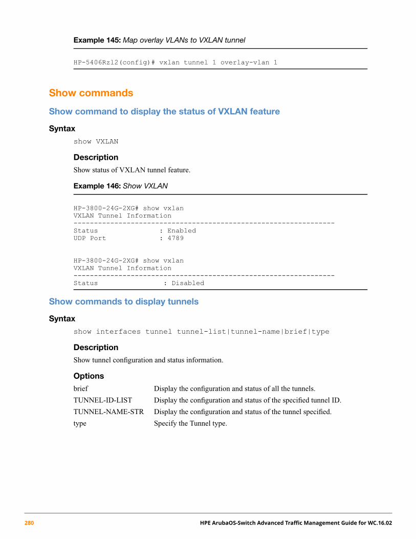
Example 145: Map overlay VLANs to VXLAN tunnel
HP-5406Rzl2(config)# vxlan tunnel 1 overlay-vlan 1
Show commands
Show command to display the status of VXLAN feature
Syntax
show VXLAN
Description
Show status of VXLAN tunnel feature.
Example 146: Show VXLAN
HP-3800-24G-2XG# show vxlanVXLAN Tunnel Information----------------------------------------------------------------Status : EnabledUDP Port : 4789
HP-3800-24G-2XG# show vxlanVXLAN Tunnel Information----------------------------------------------------------------Status : Disabled
Show commands to display tunnels
Syntax
show interfaces tunnel tunnel-list|tunnel-name|brief|type
Description
Show tunnel configuration and status information.
Options
brief Display the configuration and status of all the tunnels.
TUNNEL-ID-LIST Display the configuration and status of the specified tunnel ID.
TUNNEL-NAME-STR Display the configuration and status of the tunnel specified.
type Specify the Tunnel type.
280 HPE ArubaOS-Switch Advanced Traffic Management Guide for WC.16.02

Example 147: Show interfaces tunnel
HP-3800-24G-2XG# show interfaces tunnel
Tunnel Configuration :
Tunnel : tunnel-1Tunnel Name : VxLAN_TTunnel Status : EnabledSource Address : 2.3.4.6Destination Address : 2.3.4.7Mode : 6in4TOS : -1TTL : 64IPv6 : DisabledMTU : 1280
Current Tunnel Status :Tunnel State : UpDestination Address Route : 2.3.4.0/24Next Hop IP : 2.3.4.7Next Hop Interface : vlan-50Next Hop IP Link Status : UpSource Address : Configured on vlan-50
Tunnel Configuration :
Tunnel : 100664146Tunnel Name : ServiceTunnel01Tunnel Status : EnabledSource Address : 2.3.4.6Destination Address : 1.2.4.4Mode : Service TunnelTOS : 0TTL : 64IPv6 : n/aMTU : 1468
Current Tunnel Status :Interface State : UpDestination Address Route : 0.0.0.0/0Next Hop IP : 120.92.82.129Next Hop Interface : vlan-1Next Hop IP Link Status : UpSource Address : 2.3.4.6
Tunnel Configuration :Tunnel : 201327442Tunnel Name : VxLAN_Tunnel01Tunnel Status : EnabledSource Address : 10.0.0.1Destination Address : 10.0.0.2Mode : VXLAN TunnelTOS : -1TTL : 64IPv6 : n/aMTU : 1460
Chapter 9 VXLAN 281

Current Tunnel Status :Tunnel State : UpDestination Address Route : 10.0.0.0/8
Next Hop IP : 10.0.0.2Next Hop Interface : vlan-20Next Hop IP Link Status : UpSource Address : 10.0.0.1
Tunnel Configuration :
Tunnel : 201327443Tunnel Name : VxLAN_Tunnel02Tunnel Status : EnabledSource Address : 10.0.0.1Destination Address : 11.0.0.2Mode : VXLAN TunnelTOS : -1TTL : 64IPv6 : n/aMTU : 1280
Current Tunnel Status :
Tunnel State : DownDown Reason : TEP Not ReachableDestination Address Route :Next Hop IP :Next Hop Interface :Next Hop IP Link Status :Source Address : 10.0.0.1
9 Show VXLAN tunnel statistics
Syntax
show interfaces tunnel type vxlan statistics tunnelifindex |tunnelname-str
Description
Show the statistics of the VXLAN tunnels.
Options
tunnelifindex Show statistics of the specified VXLAN tunnel ID.
tunnelname-str Show statistics of the specified VXLAN tunnel.
282 HPE ArubaOS-Switch Advanced Traffic Management Guide for WC.16.02

Example 148: Show statistics of the specified VXLAN tunnel ID
HP-3800-24G-2XG# show interfaces tunnel type vxlan statistic 201327443Tunnel Name : VxLAN_Tunnel02Rx Packets : 0Tx Packets : 0Rx 5 Minute Weighted Average Rate (Pkts/sec) : 0Tx 5 Minute Weighted Average Rate (Pkts/sec) : 0
Example 149: Show interfaces tunnel type VXLAN statistics tunnelname
HP-3800-24G-2XG# show interfaces tunnel type vxlan statisticsVxLAN_Tunnel02Tunnel Index : 201327443Rx Packets : 0Tx Packets : 0Rx 5 Minute Weighted Average Rate (Pkts/sec) : 0Tx 5 Minute Weighted Average Rate (Pkts/sec) : 0
Validation Rules
Error/Warning/PromptValidation
VXLAN Tunnels
VXLAN tunnel %s does not exist.Attempting to display nonexistentVXLAN tunnel entry.
Virtual Network ID %s does not exist.Attempting to display nonexistentvirtual network entry.
VXLAN tunnel %s does not exist.Attempting to delete or clearnonexistent statistics informationfor the VXLAN tunnel entry.
Maximum limit of 64 VXLAN tunnels has beenreached.
VXLAN tunnel creation is not allowedif it exceeds the max limit of 64.
Allowed only on v3 modules.Attempting to create VXLAN tunnelchassisGetCompatibilityMode.
The specified VXLAN tunnel does not exist.Attempting to delete VXLAN entrypassing wrong index.
VXLAN tunnel name currently in use.Duplicate VXLAN tunnel name notallowed.
VXLAN tunnel name %s already exists.Attempting to use an existing VXLANtunnel name.
Invalid IP address.Attempting to create a tunnel sourceor destination address with aninvalid IP address.
Only IPv4 address type is supported.Only IPv4 ip address type is allowedin the creation of a VXLAN tunnel.
Chapter 9 VXLAN 283

Error/Warning/PromptValidation
VXLAN Tunnels
Local IP address is a multicast IP address.If specific local IP is Multicast —VXLAN tunnel creation is notallowed.
Remote IP address is a multicast IP address.If specified remote IP is Multicast —VXLAN tunnel creation is notallowed.
Specified source IP address is configured byDHCP.
If specified local IP is configured forDHCP — VXLAN tunnel creation isnot allowed.
Specified source IP address is not configuredon any interface.
If specified local IP is not part of anyinterface — VXLAN tunnel creationis not allowed.
Specified remote IP address is configured onthe interface.
If specified remote IP is already partof any interface — VXLAN tunnelcreation is not allowed.
Specified remote IP address is configured onthe loopback interface.
VXLAN tunnel creation is not allowedif specified remote IP is already partof loopback interface.
Cannot assign IP address to the VLAN or theloopback interface when configured as aVXLAN tunnel destination IP.
Cannot assign IP address to theVLAN or the loopback interfacebecause it is configured as a VXLANTunnel remote IP.
Configured as a VXLAN tunnel sourceIP-cannot remove this VLAN interface IPaddress.
Cannot delete the specified VxLANtunnel local address after VXLANtunnel has been created.
Cannot configure the VXLAN tunnel namebecause the name is not a valid display stringor is blank or it exceeds 31 characters.
Cannot set a tunnel name whichexceeds 31 characters.
Cannot delete the VXLAN tunnel —mappedto a VLAN.
When a VLAN ismapped to a tunnel,deletion of the tunnel is not alloweduntil the association between theVLAN and the tunnel is broken.
When Q-in-Q is enabled on the device, aVXLAN tunnel cannot be configured.
QinQ and VxLAN tunnels cannot beconfigured together — mutuallyexclusive.
Cannot apply IPv4 or IPv6 ACL on a VXLANtunnel interface.
<Interface> IPv4/v6 ACLs are notsupported on VXLAN tunnels.
Cannot enable DT when a VXLAN tunnel isconfigured on the device.
Enable the DT on the switch whenthe VXLAN tunnel is already exist.
Cannot create a VXLAN tunnel when DT isenabled on the device.
Creating a VXLAN tunnel when DT isenabled on the switch.
Cannot enable MAC-based mirroring whena VXLAN tunnel is configured on the device.
MAC based mirroring cannot beconfigured when VXLAN tunnels areconfigured. MAC based mirroring ismutually exclusive.
284 HPE ArubaOS-Switch Advanced Traffic Management Guide for WC.16.02
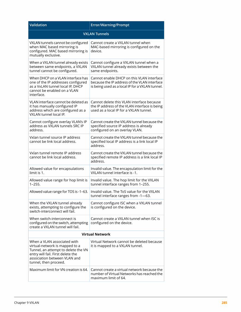
Error/Warning/PromptValidation
VXLAN Tunnels
Cannot create a VXLAN tunnel whenMAC-based mirroring is configured on thedevice.
VXLAN tunnels cannot be configuredwhen MAC based mirroring isconfigured. MAC based mirroring ismutually exclusive.
Cannot configure a VXLAN tunnel when aVXLAN tunnel already exists between thesame endpoints.
When a VXLAN tunnel already existsbetween same endpoints, a VXLANtunnel cannot be configured.
Cannot enable DHCP on this VLAN interfacebecause the IP address of the VLAN interfaceis being used as a local IP for a VXLAN tunnel.
WhenDHCPon a VLAN interface hasone of the IP addresses configuredas a VxLAN tunnel local IP, DHCPcannot be enabled on a VLANinterface.
Cannot delete this VLAN interface becausethe IP address of the VLAN interface is beingused as a local IP for a VXLAN tunnel.
VLAN interface cannot be deleted asit has manually configured IPaddress which are configured as aVXLAN tunnel local IP.
Cannot create the VXLAN tunnel because thespecified source IP address is alreadyconfigured on an overlay VLAN.
Cannot configure overlay VLAN’s IPaddress as VXLAN tunnels SRC IPaddress.
Cannot create the VXLAN tunnel because thespecified local IP address is a link local IPaddress.
Vxlan tunnel source IP addresscannot be link local address.
Cannot create the VXLAN tunnel because thespecified remote IP address is a link local IPaddress.
Vxlan tunnel remote IP addresscannot be link local address.
Invalid value. The encapsulation limit for theVXLAN tunnel interface is -1.
Allowed value for encapsulationslimit is 1.
Invalid value. The hop limit for the VXLANtunnel interface ranges from 1–255.
Allowed value range for hop limit is1–255.
Invalid value. The ToS value for the VXLANtunnel interface ranges from -1—63.
Allowed value range for TOS is -1–63.
Cannot configure ISC when a VXLAN tunnelis configured on the device.
When the VXLAN tunnel alreadyexists, attempting to configure theswitch-interconnect will fail.
Cannot create a VXLAN tunnel when ISC isconfigured on the device.
When switch-interconnect isconfigured on the switch, attemptingcreate a VXLAN tunnel will fail.
Virtual Network
Virtual Network cannot be deleted becauseit is mapped to a VXLAN tunnel.
When a VLAN associated withvirtual-network is mapped to aTunnel, an attempt to delete the VNentry will fail. First delete theassociation between VLAN andtunnel, then proceed.
Cannot create a virtual network because thenumber of Virtual Networks has reached themaximum limit of 64.
Maximum limit for VN creation is 64.
Chapter 9 VXLAN 285

Error/Warning/PromptValidation
VXLAN Tunnels
Cannot configure the virtual network namebecause the name is not a valid UI displaystring or is blank or it exceeds 31 characters.
Maximum characters to set a virtualnetwork name is 31 characters.
Virtual Network cannot be mapped to adynamic VLAN.
Cannot associate dynamic VLANs(GVRP and MVRP) while creatingvirtual network entry.
Cannot configure the virtual network nameas it is currently in use.
VN name must not be duplicated.
Virtual network ID is not valid. The validrange is 1 to 1048575.
Virtual- network ID range is 1–16777215.
Virtual network %s does not exist.Attempting to delete VN recordwhich does not exist will fail.
The VLAN is already mapped to anotherVirtual Network.
A Virtual Network ID cannot be partof more than one VLAN.
VLAN ID does not exist.Non existing VLAN cannot beassociated with virtual network.
The VLAN cannot be deleted because it ismapped to a Virtual Network.
Attempting delete VLAN associatedto VN will fail.
Cannot enable meshing when a virtualnetwork is configured on the device.
If Virtual-networks are configured,meshing at the global level is notallowed — It is mutually exclusive.
Cannot configure a virtual network whenMeshing is enabled on the device.
Virtual-networks are not allowed Ifmeshing is configured. It is mutuallyexclusive.
Cannot enable Q-in-Q when virtual networkis configured on the device.
QinQ can not be configured at theglobal level if VNs are configured. Itis mutually exclusive.
Cannot configure a virtual network whenQ-in-Q is enabled on the device.
If QinQ is configured, we do notallow Virtual-networks to beconfigured. It’s Mutually exclusive.
VLANip RIP|OSPF|igmp|irdp • RIP cannot be enabled on overlay VLANs.
• OSPF protocol cannot be enabled onoverlay VLANs.
• IGMP cannot be enabled on overlayVLANs.
• IRDP cannot be enabledonoverlay VLANs.
• IGMPproxy domain cannot be associatedwith overlay VLANs.
VLAN IGMP Proxy
IPv6 does not support overlay VLANs.VLAN ipv6 MLD|ND| OSPF3
The VLAN associated with DHCP Snoopingcannot be associated with a virtual network.
Vlan associated to DHCP snoopingcannot be associated to virtualnetwork entry.
286 HPE ArubaOS-Switch Advanced Traffic Management Guide for WC.16.02

Error/Warning/PromptValidation
VXLAN Tunnels
ARP protect cannot be enabled on overlayVLANs.
Arp protection cannot be enabledon overlay VLANs.
Cannot create a virtual network when theswitch is in module compatibility mode. The
Cannot create a Virtual Networkwhen the switch is in compatibility
module compatibility mode can be disabledmode. The compatibility mode canby executing the [no] allow-v1-modulescommand.
be disabled by executing the [no]allow-v1-modulescommand.
Cannot create a virtual network when theswitch is in module compatibility mode. The
Cannot create a Virtual Networkwhen the switch is in compatibility
module compatibility mode can be disabledmode. The compatibility mode canby executing the [no] allow-v1-modulescommand.
be disabled by executing the [no]allow-v2-modules command.
Module compatibility mode cannot beenabledwhen a virtual network is configuredon the device.
Compatibility mode cannot beenabled when a Virtual Network isconfigured on the device.
Cannot create a virtual network because thespecified IP address of the VLAN interface isbeing used as a source IP for a VXLAN tunnel.
Cannot make VLAN as overlay, if itsIP address configured as VXLANtunnels SRC-IP.
IPv6 or IPv4 access group cannot be enabledon overlay VLANs.
IPv6 or IPv4 access group cannot beenabled on overlay VLANs.
Cannot configure the VLAN as an overlayVLAN because the specified VLAN has IPv6address configured.
Unable to make a VLAN as anoverlay if the IPv6 addressconfiguration attempted on thesame VLAN.
Cannot configure the VLAN as an overlayVLAN because the specified VLAN has IPv6ND parameters configured.
If IPv6 ND is enabled on a VLAN,VLAN can not be used as an overlay.
Cannot configure the VLAN as an overlayVLAN because the specified VLAN has IPv6ND RA parameters configured.
If IPv6 ND RA is enabled on a VLAN,VLAN can not be used as an overlay.
Cannot configure the VLAN as an overlayVLAN because the specified VLAN has IPv6OSPF3 enabled.
If IPv6 OSPF3 is enabled on a VLAN,that VLAN can not be created as anoverlay.
Cannot configure the VLAN as an overlayVLAN because the specified VLAN has IPv6MLD parameters configured.
If IPv6 MLD is enabled on a VLAN,that VLAN can not be an overlay.
Cannot configure the VLAN as an overlayVLAN because the specified VLAN has IPv6DHCP-client configured.
If IPv6 DHCP-client is enabled on aVLAN, that sameVLAN cannot be anoverlay.
Cannot configure the VLAN as an overlayVLAN because the specified VLAN has IPv6helper-address configured.
If IPv6 helper-address is enabled ona VLAN, that same VLAN can not bean overlay.
Cannot configure the VLAN as an overlayVLAN because the specified VLAN has IPv6enabled.
If IPv6 is enabled on a Vlan, thatsame VLAN can not be used as anoverlay.
Chapter 9 VXLAN 287

Error/Warning/PromptValidation
VXLAN Tunnels
Cannot configure the VLAN as an overlayVLAN because the specified VLAN has IPv6access-group configured.
If IPv6 group-access is enabled on aVlan, that same VLAN can not beused as an overlay.
Cannot configure the VLAN as an overlayVLAN because the specified VLAN has RIPconfigured.
If IPv6 RIP is enabled on a Vlan, thatsame VLAN can not be used as anoverlay.
Cannot configure the VLAN as an overlayVLAN because the specified VLAN has OSPFconfigured.
If IPv6 OSPF is enabled on a Vlan,that same VLAN can not be used asan overlay.
Cannot configure the VLAN as an overlayVLAN because the specified VLAN has IGMPconfigured.
If IPv6 IGMP is enabled on a Vlan,that same VLAN can not be used asan overlay.
Cannot configure the VLAN as an overlayVLAN because the specified VLAN has IRDPconfigured.
If IPv6 IRDP is enabled on a Vlan, thatsame VLAN can not be used as anoverlay.
Cannot configure the VLAN as an overlayVLAN because the specified VLAN has IPv4access-group configured.
If IP access-group is enabled on aVlan, that same VLAN can not beused as an overlay.
Cannot configure the VLAN as an overlayVLAN because the specified VLAN hasigmp-proxy configured.
If IGMP-proxy is enabled on a Vlan,that same VLAN can not be used asan overlay.
Cannot configure the VLAN as an overlayVLAN because the specified VLAN hasARP-protect configured.
If ARP-protect is enabled on a VLAN,that same VLAN can not be used asan overlay.
IP source-binding cannot be enabled onoverlay VLANs.
IP source-binding cannot be enabledon overlay VLANs.
VLAN to Tunnel Mapping
VLAN ID does not exist.If VLAN ID passed as index is not inthe proper range 1–4094, and theVLAN id not yet created, it will fail.
The VXLAN tunnel index is not in range.Tunnel Index passed must be inVxLAN tunnel index range.
VLAN ID is not associated with any VirtualNetwork.
VN entries will fail if the specifiedVLAN ID is not associated.
The specified VLAN is alreadymapped to theVXLAN tunnel.
Mapping a VLAN to tunnel indexwhere the record already exist in theconfiguration will fail.
The VLAN-to-Tunnel map entry does notexist.
Deleting themap for a specific VLANto tunnel will fail if the mappingrecord not found.
288 HPE ArubaOS-Switch Advanced Traffic Management Guide for WC.16.02

Chapter 10
BYOD-redirect
IntroductionThe HPE BYOD (bring-your-own-device) solution lets you design, manage, and control a BYOD network whenyou configure the BYOD-redirect feature on your switches.
Where BYOD-redirect is enabled on a switch, the device’s client credentials are sent to the BYOD server forregistration. The BYOD server stores the registration information for each client’s device (such as the deviceMAC-address), which gives that client’s device access to the network.
The BYOD solution includes:
• secure user authentication
• centralized authentication process
• authorization and accounting
• unified monitoring and network management services
• ease-of-use self-registration (on-boarding) process
Chapter 10 BYOD-redirect 289

Example 150: BYOD solution
Figure 49 (page 290) illustrates a BYOD solution that includes the following:
• Access point and wireless controller: manages wireless SSIDs.
• BYOD (IMC) server: manages BYOD policy and centralized user management.
• switches: redirects user registration traffic to IMC and grants port.
• BYOD Redirect feature: supported on ProVision switches.
Figure 49: BYOD solution
FeaturesWhen BYOD-redirect is enabled on a VLAN, the BYOD feature intercepts HTTP traffic and blocks all other trafficfor which free rules are not enabled. Most BYOD-redirect implementation is platform independent, except installingfree rules to mitigate risks.
Communication between clients and the IMC server is tunneled by the edge switch:
1. A client request is read by the HTTP task.2. The HTTP task always redirects, after embedding client IP addresses, a URL trying to access the redirected
URL.3. The redirect response includes URL parameters: user ip address and url user is trying to access.4. The client receives a redirect response from the switch and makes an HTTP request to redirect the URL.
290 HPE ArubaOS-Switch Advanced Traffic Management Guide for WC.16.02

Figure 50: The BYOD-redirect function
Figure 51: BYOD-redirect on VLAN
BYOD task listenson port
Host Stack Recv Host Stack Xmit
IP Pkt RecvSwitch IP
IP Pkt XmitReal IP
1. BYOD-redirect on vlan2. Redirect server configuration3. BYOD-redirect debugging
Other apps. CLI/SNMP
config
BYOD Task
IP protocol stack
VLS
Packets Rx/Tx TCAM
Chapter 10 BYOD-redirect 291

SNMP InteractionsBYOD updates server details using the BYOD VLAN map and TCAM rules from an SNMP communication, handlingdynamic reconfiguration events by BYOD task:
1. To configure a BYOD server:
Internal data structure is updated, including the server URL, server IP, port, and other parameters.
2. To enable BYOD-redirect on a VLAN:
The following TCAM rules are installed:
• Steal and hardware drop for http traffic (80).
• Drop (IP traffic) all rules to be installed.
• Install hardware forward rule for http packets to the BYOD server.
• Allow ARP packets any to any.
3. Configure free rules to allow traffic to DNS, DHCP, and other traffic.
Interoperability with other switch featuresThe following rules can help avoid conflicts when BYOD-redirect has been deployed on a switch with other features:
1. MAFR and BYOD-redirect are mutually exclusive – MAFR and BYOD-redirect solve similar problems.2. DNS sentinel and BYOD-redirect – When a DNS sentinel is enabled, the switch tunnels packets to the
controller. Packets are re-injected to the switch only if the controller classifies DNS packets as permitted. WhenBYOD-redirect is enabled, the user should configure an ACL rule to pass through DNS packets to the switch.If SDN controller policy classifies a DNS packet originating from a client as drop, then BYOD-redirect doesnot work.
3. IP sentinel and BYOD-redirect – When IP sentinel is enabled for the IP flows configured by the SDN controller,the switch tunnels the IP packets to the controller. The IP packets are reinjected to the switch only if the controllerclassifies the IP traffic as not malicious. If the SDN controller policy classifies the client’s IP traffic as malicious,then BYOD-redirect fails.
4. OpenFlow and BYOD-redirect – If an OpenFlow instance is enabled on a VLAN, then all traffic is given tothe OpenFlow packet processing task. BYOD-redirect requires intercepting IP (HTTP) packets. If BYOD-redirectinteroperates with OpenFlow, traffic should be copied to both OpenFlow and BYOD-redirect; otherwise, theswitch cannot enable BYOD-redirect and OpenFlow on the same VLAN.
5. Other TCAM rules – If any other user has configured TCAM rules that override TCAM entries installed forBYOD-redirect, BYOD redirect does not work.
Interoperability with other vendors
Because BYOD policy integrates several logical components including MSM, UAM, and RADIUS, the redirectedURL in the BYOD-redirect feature on a switch must include the byod-server-url and user-ip informationto work with the IMC server.
BYOD-redirect configuration command syntax for ProVision software matches Comware server command syntax.
RestrictionsBYOD-redirect has the following restrictions:
1. BYOD-redirect is a per-VLAN configuration; up to three VLANs can be enabled with BYOD-redirect.2. BYOD-redirect supports up to three redirection servers configured on a switch. When a redirection server URL
is configured, the BYOD module maintains separate data structures to store the redirected URL on the VLANwhere BYOD-redirect is enabled. BYOD-redirect statistics are maintained for each server.
292 HPE ArubaOS-Switch Advanced Traffic Management Guide for WC.16.02

Configuring
Creating a BYOD serverConfigure a portal redirect web-server.
Syntax
[no] portal web-server [web-server-name] url [url-string]
portal: Configure the BYOD redirect feature.
web-server-name: Configure portal redirect web-server.
url: Configure the URL of the BYOD server.
url-string: A URL redirecting the client to the BYOD server must be in ASCII.
Associating a BYOD server
Associate a BYOD server with a specific VLAN to redirect clients to the assigned URL page.
Syntax
[no] vlan [vlan-id] <portal web-server [web-server-name]>
vlan: Add, delete, edit VLAN configuration, or enter a VLAN context.
vlan-id: VLAN identifier or VLAN name.
portal: Configure the BYOD redirect feature on a VLAN.
web-server: Specify the BYOD web-server.
web-server-name: BYOD web-server name in ASCII.
Creating a BYOD ACL rule
Configure a BYOD-free rule.
Syntax
[no] portal free-rule [rule-number] vlan [VLAN-ID] destination<<ip-address> | mask <mask-length> | any tcp <des-tcp-port> | udp<des-udp-port> | source <ip-address> | mask <mask-length> | anytcp <src-tcp-port> |udp <src-udp-port>>
MeaningTerm
Configure the BYOD redirect feature.portal
Configure a BYOD-free rule.free-rule
Free rule number as an INTEGER<1-6>.rule-number
Free rule source VLAN ID.vlan
VLAN identifier or VLAN name.VLAN-ID
Free rule destination.destination
IP addressip-address
Maskmask
Mask length.mask-length
Chapter 10 BYOD-redirect 293
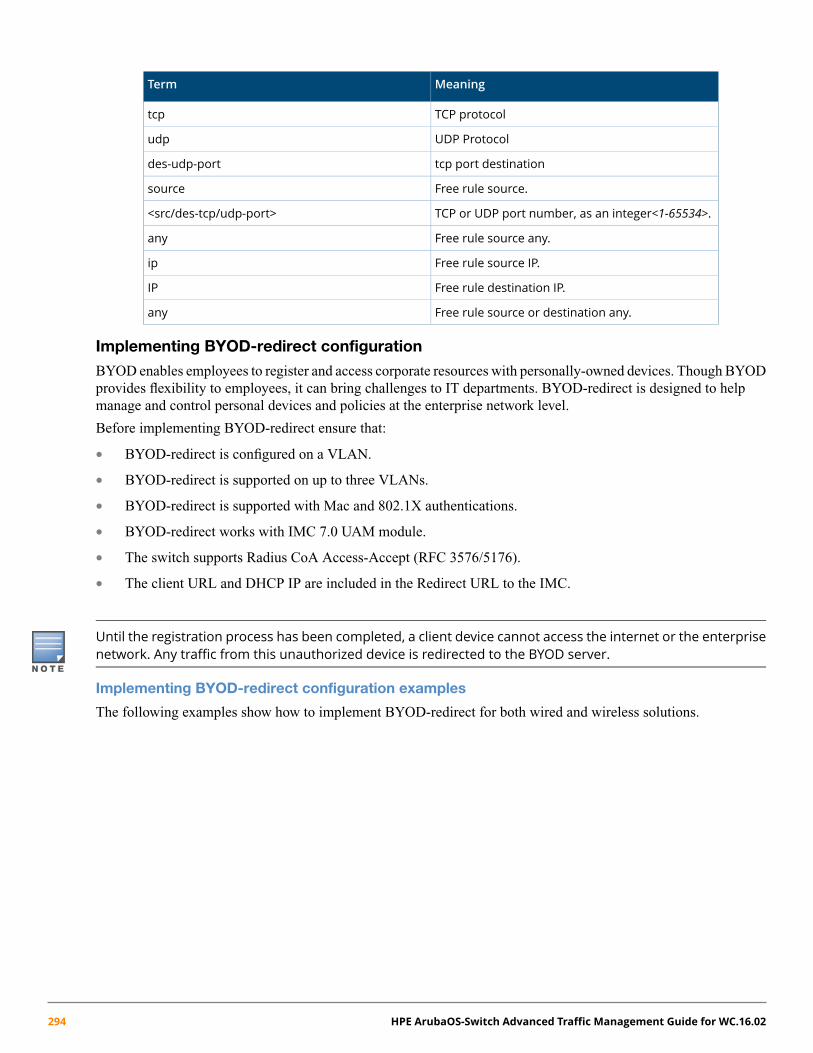
MeaningTerm
TCP protocoltcp
UDP Protocoludp
tcp port destinationdes-udp-port
Free rule source.source
TCP or UDP port number, as an integer<1-65534>.<src/des-tcp/udp-port>
Free rule source any.any
Free rule source IP.ip
Free rule destination IP.IP
Free rule source or destination any.any
Implementing BYOD-redirect configuration
BYOD enables employees to register and access corporate resources with personally-owned devices. Though BYODprovides flexibility to employees, it can bring challenges to IT departments. BYOD-redirect is designed to helpmanage and control personal devices and policies at the enterprise network level.
Before implementing BYOD-redirect ensure that:
• BYOD-redirect is configured on a VLAN.
• BYOD-redirect is supported on up to three VLANs.
• BYOD-redirect is supported with Mac and 802.1X authentications.
• BYOD-redirect works with IMC 7.0 UAM module.
• The switch supports Radius CoA Access-Accept (RFC 3576/5176).
• The client URL and DHCP IP are included in the Redirect URL to the IMC.
Until the registration process has been completed, a client device cannot access the internet or the enterprisenetwork. Any traffic from this unauthorized device is redirected to the BYOD server.
Implementing BYOD-redirect configuration examples
The following examples show how to implement BYOD-redirect for both wired and wireless solutions.
294 HPE ArubaOS-Switch Advanced Traffic Management Guide for WC.16.02

Example 151: BYOD configuration on a distribution switch
To facilitate the BYOD-redirect function, complete the following tasks on the distribution switch:
1. Configure DNS and make FQDN solution successful: ip dns server-address priority 1<DNS-server-IP>.
The argument to the URL can be an FQDN or IP address. If you use the IP address as an argument, thisstep is not necessary.
2. Configure BYOD web-server URL: portal web-server "byod" url http://imc.com:8080/byod.3. Enable BYOD-redirect on a VLAN: vlan 101 portal web-server "byod."4. Configure BYOD-redirect free-rules on the on-boarding VLAN 101 to permit client traffic transit through DNS
and DHCP servers using the following commands.
To permit DNS traffic to/from a DNS server to a client through on-boarding VLAN:
a. portal free-rule 1 vlan 101 source any udp 0 destination any udp 53b. portal free-rule 2 vlan 101 source any udp 53 destination any udp 0
To permit DHCP traffic to/from DHCP server to client through on-boarding VLAN:
a. portal free-rule 3 vlan 101 source any udp 68 destination any udp 67b. portal free-rule 4 vlan 101 source any udp 67 destination any udp 68
5. Register device in IMC on the on-boarding VLAN. When registration is successful, client traffic is placed intodifferent VLAN (guest/corporate) configurations.
Example 152: Client authentication configuration on edge switch
Enable MAC authentication on edge switch port 1-2 using the following commands:
• # enable mac authentication on ports 1-2
• aaa port-access mac-based 1-2
• # configure number of client limits on port 1 and port2
• aaa port-access mac-based 1 addr-limit 32
• aaa port-access mac-based 2 addr-limit 32
• radius-server host <radius ip> dyn-authorization
• radius-server host <radius ip> time-window 0
Chapter 10 BYOD-redirect 295

Table 30: Wired and wireless components configured in a network topology
Configuration ProcedureNoteDistribution SwitchEdge SwitchAccess Type
5400 switch2530 switchWired Access 1. Register the 2530 switch in HPE IMC.2. Create the configuration on 2530
switch.3. Create the configuration on 5400
switch.
Wireless Access 1. Make the HPE MSM controllerreachable by IMC.
2. Ensure that access points (HPE 422)are managed by the MSM controller.
3. Configure MAC or 802.1Xauthentication on theMSM controller.
4. Create the configuration on the 5400switch.
Figure 52: Wired and wireless components configured in a network topology
Table 31: Wired clients solution
Configuration ProcedureDistribution SwitchEdge SwitchAccess Type
3800 switch2530 switchWired Access 1. Register the 2530 switch and 3800 switch in IMC.2. Ensure that both 2530 switch and 3800 switch can
reach the DHCP and DNS server.3. Create the configuration on 2530 switch.4. Create the configuration on 3800 switch.
296 HPE ArubaOS-Switch Advanced Traffic Management Guide for WC.16.02

Figure 53: Wired clients solution
Table 32: Configuration and access for wired clients on an edge switch
Configuration ProcedureDistribution SwitchEdge SwitchAccess Type
N/A3500 switchWired Access 1. Register the 3500 switch in IMC.2. Ensure that the 3500 switch is reachable by
the DHCP and DNS server.3. Create the configuration on the 3500 switch.4. Create the following configuration on the
3500 switch.
Figure 54: Configuration and access for wired clients on an edge switch
Show commands
Show portal server
Display all BYOD servers and their attributes or specify a BYOD web-server-name to display its details.
Chapter 10 BYOD-redirect 297

Syntax
show portal web-server [web-server-name]
MeaningTerm
Display BYOD server details..portal
Specify the BYOD web-server.web-server
Enter BYOD web-server name in ASCII.web-server name
Sample output
Portal Server:1)imc:Resolved IP : 15.146.197.224VPN Instance : n/aURL : http://15.146.197.224:80/byodVLAN : 101DNS Cache Status : 20 seconds
Show portal redirect statistics
Show redirect statistics of a BYOD.
Syntax
show portal redirect statistics
MeaningTerm
Display BYOD server details.portal
Display redirect statisticsredirect
Display the statistics.statistics
Example 153: Sample output
show portal redirect statisticsStatus and Counters - Portal Redirect InformationTotal Opens : 0Resets Connections : 0Current Opens : 0Packets Received : 14997Packets Sent : 12013HTTP Packets Sent : 3002Current Connection States :SYN_RECVD : 0ESTABLISHED : 0
Show portal free rule
Display all BYOD free rules and their attributes; the user can specify a BYOD rule to display its free rule.
298 HPE ArubaOS-Switch Advanced Traffic Management Guide for WC.16.02

Syntax
show portal free-rule [free-rule-number]
MeaningTerm
Display BYOD server details.portal
Display BYOD-free rule.free-rule
Free rule number as an integer <0-50>.free-rule-number
Example 154: Sample output
Rule-Number : 2Vlan : 0Source:Protocol : UDPPort : 12345IP : 0.0.0.0Mask : 0.0.0.0MAC : n/aInterface : n/aDestination:Protocol : UDPPort : 123IP : 0.0.0.0Mask : 0.0.0.0
Associating with the BYOD server on a specified VLANAssociate a BYOD server with a specific VLAN to redirect clients to the assigned URL page.
Syntax
[no] vlan <VLAN-ID > [portal web-server < web-server-name>]
MeaningTerm
Configure the BYOD redirect feature on the VLAN.portal
Specify the BYOD web-server.web-server
BYOD web server name.ASCII-STR
Add, delete, edit VLAN configuration, or enter aVLAN context.
vlan
Enter a VLAN identifier or a VLAN name.VLAN-ID
Chapter 10 BYOD-redirect 299

Chapter 11
QinQ (Provider bridging)
All commands previously in the Summary of commands table are indexed under the entry Command syntax.
IntroductionThis chapter describes how to enable QinQ operations on the switch and how to configure provider bridge S-VLANsand port assignments.
The IEEE 802.1ad specification, commonly known as QinQ or provider bridging, extends the IEEE 802.1Q standardby providing for a second tier of VLANs in a bridged network. The general purpose of QinQ is to allow framesfrom multiple customers to be forwarded (or tunneled) through another topology (provider network) using serviceVLANs or S-VLANs. The provider bridge, which may comprise multiple devices in the service provider domain,looks like a simple bridge port to the customer's traffic and maintains the customer's VLANs.
Figure 55 (page 300) shows a sample QinQ topology and use model. Customer A has LANs spread across multiplesite locations and may want to link them together in a single logical LAN. To do this, the customer could have acable laid out for the entire distance interconnecting the three sites. A more cost-effective and scalable alternative,however, would be to tunnel frames through the provider's network to interconnect all the sites subscribing to theservice. This solution can be delivered using QinQ.
Figure 55: QinQ network diagram
The Service Provider and customers may belong to the same business entity, as in the case where a singleenterprise uses QinQ to help segregate local networks and increase the scalability of their backboneinfrastructure.
300 HPE ArubaOS-Switch Advanced Traffic Management Guide for WC.16.02

How QinQ worksUnder QinQ, the provider network operates on a different VLAN space, independent of the VLANs that are usedin the customer network.
Figure 56: VLANs in a QinQ configuration
Customer VLANs (referred to as C-VLANs by the IEEE 802.1ad specification) are not used to make any forwardingdecisions inside the provider network where customer frames get assigned to service VLANs (S-VLANs). Insidethe provider cloud, frames are forwarded based on the S-VLAN tag only, while the C-VLAN tag remains shieldedduring data transmission. The S-VLAN tag is removed when the frame exits the provider network, restoring theoriginal customer frame.
Features and benefits
• Increases the VLAN space in a provider network or enterprise backbone.
• Reduces the number of VLANs that a provider needs to support within the provider network for the samenumber of customers.
• Enables customers to plan their own VLAN IDs, without running into conflicts with service provider VLANIDs.
• Provides a simple Layer 2VPN solution for small-sized MANs (Metropolitan Area Networks) or intranets.
• Provides for customer traffic isolation at Layer 2 within a Service Provider network.
Configuring QinQQinQ must be configured on all the devices and ports participating in the provider bridge. Typically, customer facingports are configured as untagged members of S-VLANs and provider facing ports are configured as tagged membersof S-VLANs. Per the IEEE 802.1ad specification, there is no condition binding port types (customer or provider)to untagged or tagged S-VLAN memberships. Therefore, when configuring QinQ tunnelling on the switch, youwould first configure per-port S-VLAN membership (tagged or untagged), and then configure the port type ascustomer-network or provider-network, depending on the device to which the switch port is connected.
Chapter 11 QinQ (Provider bridging) 301

A customer-network port can receive S-VLAN tagged frames if the customer and provider agree on the S-VIDassociation for that customer and the customer device is capable of sending S-VLAN tagged frames. ConfiguringQinQ with S-VLANs in a switch stack is not supported. For more information, see “Effects of QinQ on otherswitch features” (page 318).
To configure QinQ take the following steps on all participating provider switches:
1. Enable QinQ on the device, selecting the appropriate QinQ mode (S-VLAN or mixed VLAN mode).2. Save the configuration and reboot the switch.3. Configure S-VLANs and assign per port VLAN membership.4. Configure port-types for all of the switch ports that carry QinQ traffic across the network.5. (Optional) Assign priorities to traffic passing through the provider network.
A reboot is required to enable/disable QinQ operations on the switch. When moving between QinQ modes(qinq mixedvlan to qinq svlan or vice versa), the switch boots up with a default configuration for the newqinq mode and the configuration parameters of the current mode will be erased.
QinQ Configuration exampleThis configuration example uses four switches to establish a QinQ tunnel through the provider network.
Figure 57: QinQ configuration example
The design parameters are as follows:
• The provider edge bridge and the provider core bridge are configured in svlan mode.
• Each customer is associated with a single S-VLAN connecting two separate sites: customer A's VLANs(C-VLANs 1-10) are associated with S-VLAN 100; and customer B's VLANs (C-VLANs 1-20) are associatedwith S-VLAN 200.
302 HPE ArubaOS-Switch Advanced Traffic Management Guide for WC.16.02
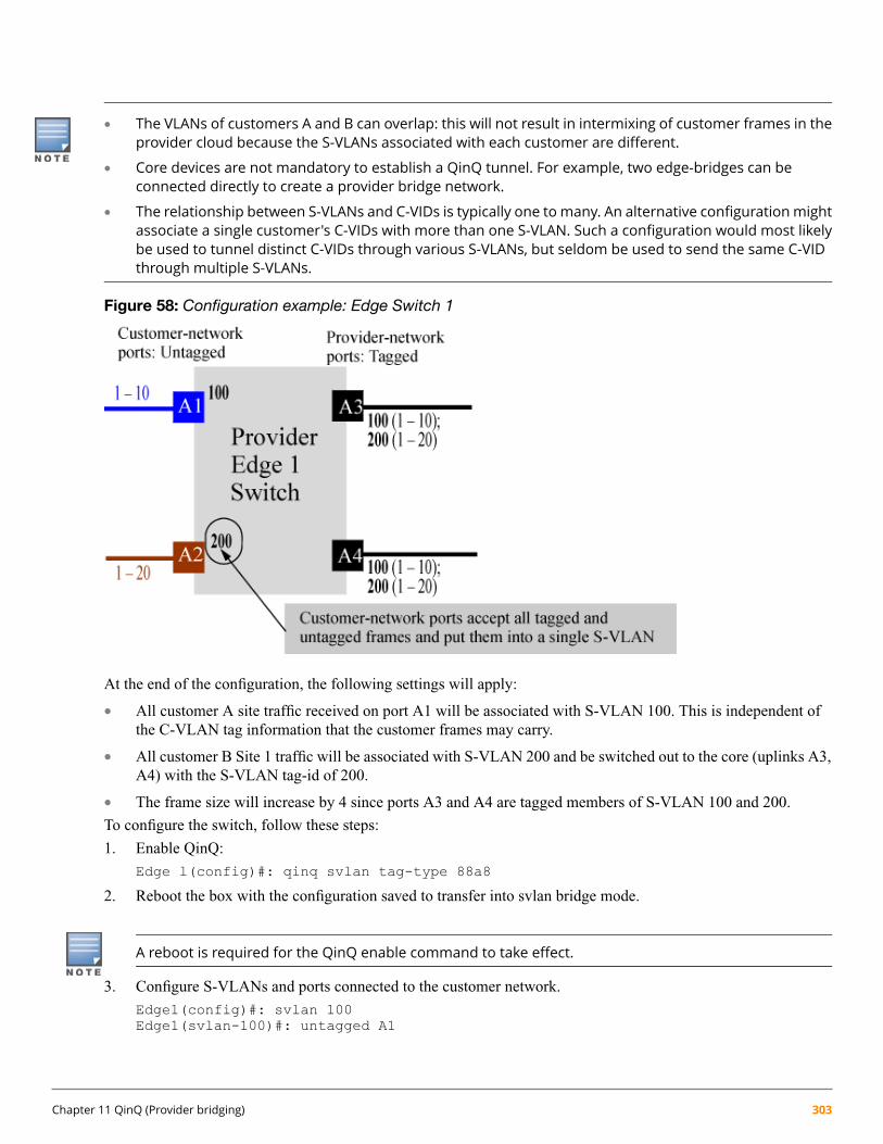
• The VLANs of customers A and B can overlap: this will not result in intermixing of customer frames in theprovider cloud because the S-VLANs associated with each customer are different.
• Core devices are not mandatory to establish a QinQ tunnel. For example, two edge-bridges can beconnected directly to create a provider bridge network.
• The relationship between S-VLANs and C-VIDs is typically one to many. An alternative configurationmightassociate a single customer's C-VIDs with more than one S-VLAN. Such a configuration would most likelybe used to tunnel distinct C-VIDs through various S-VLANs, but seldom be used to send the same C-VIDthrough multiple S-VLANs.
Figure 58: Configuration example: Edge Switch 1
At the end of the configuration, the following settings will apply:
• All customer A site traffic received on port A1 will be associated with S-VLAN 100. This is independent ofthe C-VLAN tag information that the customer frames may carry.
• All customer B Site 1 traffic will be associated with S-VLAN 200 and be switched out to the core (uplinks A3,A4) with the S-VLAN tag-id of 200.
• The frame size will increase by 4 since ports A3 and A4 are tagged members of S-VLAN 100 and 200.
To configure the switch, follow these steps:
1. Enable QinQ:
Edge l(config)#: qinq svlan tag-type 88a8
2. Reboot the box with the configuration saved to transfer into svlan bridge mode.
A reboot is required for the QinQ enable command to take effect.
3. Configure S-VLANs and ports connected to the customer network.
Edge1(config)#: svlan 100Edge1(svlan-100)#: untagged A1
Chapter 11 QinQ (Provider bridging) 303

Edge1(svlan-100)#: exitEdge1(config)#: int A1 qinq port-type customer-networkEdge1(config)#: svlan 200Edge1(svlan-200)#: untagged A2Edge1(svlan-200)#: exitEdge1(config)#: int A2 qinq port-type customer-network
Customer A is assigned S-VLAN 100 and customer B is assigned S-VLAN 200. However, the same customercan be associated with more than one SVLAN. Also, interfaces A1 and A2 are configured as customernetwork ports because they are linked to customer bridges.
4. Configure the provider ports leading to the core of the provider network.
Edge1(config)#: svlan 100 tagged A3, A4Edge1(config)#: svlan 200 tagged A3, A4Edge1(config)#: interface A3,A4 qinq port-type provider-network
As recommended by IEEE 802.1ad specification, uplink ports should generally be configured as taggedports for S-VLANs that are used to carry customer traffic. However, this is not a mandatory requirementon switches—S-VLANs that are used for internal provider network use (not carrying customer traffic butfor management of the provider network devices) can have untagged port memberships.
QinQ Configuration example: provider Edge 2 switchThe configuration details for the Edge 2 switch mirrors the configuration for the Edge 1 switch. All customer trafficreceived on port A1 from customer A's site 2 will be associated with S-VLAN 100. Similarly, all customer B's site2 traffic will be associated with S-VLAN 200.
To configure the switch, follow these steps:
1. Enable QinQ:
Edge 2(config)#: qinq svlan tag-type 88a8
2. Reboot the box with the configuration saved to transfer into S-VLAN bridge mode.3. Configure S-VLANs and customer ports connected to the customer network.
Edge2(config)#: svlan 100Edge2(svlan-100)#: untagged A1Edge2(svlan-100)#: exitEdge2(config)#: int A1 qinq port-type customer-networkEdge2(config)#: svlan 200Edge2(svlan-200)#: untagged A2Edge2(svlan-200)#: exitEdge2(config)#: int A2 qinq port-type customer-network
4. Configure the provider ports leading to the core of the provider network.
Edge1(config)#: svlan 100 tagged A3, A4Edge1(config)#: svlan 200 tagged A3, A4Edge1(config)#: interface A3,A4 qinq port-type provider-network
304 HPE ArubaOS-Switch Advanced Traffic Management Guide for WC.16.02

Configuring example: provider core 1 switch
Figure 59: Configuration example: Core 1 Switch
To configure the Core 1 switch:
1. Enable QinQ:
Core l(config)#: qinq svlan tag-type 88a8
2. Reboot the box with the configuration saved to transfer into svlan bridge mode.3. Configure S-VLANs and port assignments.
Core 1(config)#: svlan 100Core 1(svlan-100)#: tagged A1, A2Core 1(svlan-100)#: exitCore 1(config)#: svlan 200Core 1(svlan-200)#: tagged A1, A2Core 1(svlan-200)#: exitCore 1(config)#: interface A1,A2 qinq port-type provider-network
The S-VLAN configuration for the core devices is based on what VLANs the edge devices (Edge 1 and 2) cansend. Per the 802.1ad specification, all ports carrying customer traffic will be tagged on the VLAN that the portcarries customer frames on.
To configure the Core 2 switch:
1. Enable QinQ:
Core 2(config)#: qinq svlan tag-type 88a8
2. Reboot the box with the configuration saved to transfer into svlan bridge mode.3. Configure S-VLANs and port assignments.
Core 2(config)#: svlan 100Core 2(svlan-100)#: tagged A1, A2Core 2(svlan-100)#: exitCore 2(config)#: svlan 200Core 2(svlan-100)#: tagged A1, A2Core 2(svlan-100)#: exitCore 2(config)#: interface A1,A2 qinq port-type provider-network
Verifying the configurationAfter the edge and core switch configurations are completed, QinQ operations can begin. To verify operations, itshould be possible to assign IP-addresses to customer A or B devices in site 1 and site 2 and ping them. If everythinghas been configured correctly, traffic will flow through the provider network cloud and reach the other site seamlessly.
Chapter 11 QinQ (Provider bridging) 305

Enabling QinQBy default, QinQ is disabled on the switch. To enable QinQ, the switch must be put into either in mixed VLANmode or QinQ SVLAN mode by issuing one of the following commands from configuration mode on the CLI.
Syntax:qinq mixedvlan tag-type [tpid]
From configuration mode, globally enables QinQ mixed mode, an environment that supports bothS-VLAN and C-VLAN traffic on the same device. This command requires a reboot to take effect.Default: Disabled.
Syntax:qinq svlan tag-type [tpid]
From configuration mode, globally enables QinQ SVLAN mode, an S-VLAN only environmentthat supports port-based or s-tagged interfaces of the standard. Requires a reboot to take effect.Default: Disabled.
Setting up S-VLANsS-VLANs are created via the CLI using the svlan vid command.
Syntax:svlan vid | ascii-name-string
[no] svlan vid
If vid does not exist in the switch, this command creates a port-based S-VLAN with the specifiedvid. If the command does not include options, the CLI moves to the newly created S-VLAN context.If you do not specify an optional name, the switch assigns a name in the default format: svlanwhere n is the vid assigned to the S-VLAN. If the S-VLAN already exists and you enter either thevid or the ascii-name-string, the CLI moves to the specified S-VLAN's context.
The no form of the command deletes the S-VLAN as follows:
• If one or more ports belong only to the S-VLAN to be deleted, the CLI notifies you that theseports will be moved to the default VLAN and prompts you to continue the deletion. For memberports that also belong to another S-VLAN, there is no move prompt.
When QinQ is disabled, all VLANs must be C-VLANs. When QinQ is enabled in SVLANmode, all VLANs must beS-VLANs. When QinQ is enabled in mixed VLANmode, VLANs can be configured as either C-VLANs or S-VLANs.
Configuring per-port S-VLAN membershipThe svlan vid command supports tagged and untagged options to configure per-port S-VLAN memberships.Use these options from the configuration level by beginning the command with svlan vid , or from the contextlevel of the specific VLAN by entering the command option.
Syntax:svlan vid
306 HPE ArubaOS-Switch Advanced Traffic Management Guide for WC.16.02
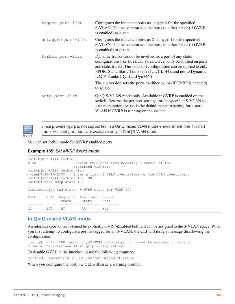
tagged port-list Configures the indicated ports as Tagged for the specifiedS-VLAN. The no version sets the ports to either No or (if GVRPis enabled) to Auto.
untagged port-list Configures the indicated ports as Untagged for the specifiedS-VLAN. The no version sets the ports to either No or (if GVRPis enabled) to Auto
forbid port-list Dynamic trunks cannot be involved as a part of any staticconfigurations like forbid. Forbid can only be applied on portsand static trunks .The forbid configuration can be applied to onlyPPORTS and Static Trunks (Trk1….Trk144), and not to DynamicLACP Trunks (Dyn1….Dyn144.)
The no version sets the ports to either no or (if GVRP is enabled)to Auto.
auto port-list QinQ S-VLAN mode only. Available if GVRP is enabled on theswitch. Returns the per-port settings for the specified S-VLAN toAuto operation. Auto is the default per-port setting for a staticVLAN if GVRP is running on the switch.
Since provider-gvrp is not supported in a QinQ mixed VLAN mode environment, the forbidand auto configurations are available only in QinQ S-VLAN mode.
You can set forbid mode for MVRP enabled ports.
Example 155: Set MVRP forbid mode
switch(eth-A1)# forbidvlan Prevent this port from becoming a member of the
specified VLAN(s).switch(eth-A1)# forbid vlan[vlan]VLAN-ID-LIST Enter a list of VLAN identifiers or one VLAN identifier.switch(eth-A1)# forbid vlan 100switch# show mvrp state 100
Configuration and Status - MVRP state for VLAN 100
Port VLAN Registrar Applicant ForbidState State Mode
-------- ----- --------- --------- ---------A1 100 MT AA Yes
In QinQ mixed VLAN modeAn interface (port or trunk) must be explicitly GVRP-disabled before it can be assigned to the S-VLAN space. Whenyou first attempt to configure a port as tagged for an S-VLAN, the CLI will issue a message disallowing theconfiguration.config#: svlan 200 tagged a1,a2 GVRP enabled ports cannot be members of svlans.Disable the interface level gvrp configuration.
To disable GVRP at the interface, issue the following command:
config#: interface a1,a2 unknown-vlans disable
When you configure the port, the CLI will issue a warning prompt:
Chapter 11 QinQ (Provider bridging) 307

config#: svlan 200 tagged a1,a2 Ports a1, a2 will lose their cvlan memberships if anyDo you want to continue? [y/n]
Press Y to continue and automatically configure both ports as port-type provider-network (the default for allS-VLAN member ports).
Configuring port-typesWhen QinQ is enabled on the switch all S-VLAN member ports must be categorized as either port-typecustomer-network or provider-network (See Figure 60 (page 308)).
Figure 60: Customer or provider ports in the provider network
All ports of a QinQ-enabled device default to provider-network. Any ports participating in the provider bridgeused to connect to customer equipment must be manually configured as port-type customer-network. In amixed mode device, ports that are members of C-VLANs and that do not participate in the provider-bridge cannotbe configured to any port-type.
The following command allows you to configure the appropriate port-type.
Syntax:[no] interface [port-list] | Trkxqinq port-type { customer-network | provider-network }
Configures the specified ports/trunks as a customer network port or provider network port.
Default: port-type provider (for QinQ S-VLAN mode)
Disabling QinQTo disable QinQ once it has been enabled, issue the following commands from configuration mode on the CLI.
Syntax:no qinq
This is the default mode when QinQ is disabled on the switch.
Moving into this configuration from another QinQ configuration requires a reboot to take effect.Upon reboot, all configuration information for the prior QinQ mode will be lost.
Default setting. Standard VLAN operations apply.
308 HPE ArubaOS-Switch Advanced Traffic Management Guide for WC.16.02

Changing VLAN port memberships (mixed VLAN mode)On mixed VLAN mode devices, certain per-port features are not supported on S-VLANs that are supported onC-VLANs. Ports that are currently members of a regular VLAN can move to an S-VLAN only if there is no conflictingconfiguration.
To avoid a misconfiguration, HPE recommends that you use a default interface configuration when movingports between C-VLANs and S-VLANs.
When configuring S-VLAN port memberships using the svlan command, the CLI issues a warning and promptif any of the ports listed already belong to a regular VLAN. For example:
switch(config)#: svlan 200 tagged a1,a2Ports a1, a2 will lose their cvlan memberships if any.Do you want to continue: y/n?
The warning prompt is displayed only when there is at least one port in the port list that needs to be moved out fromthe C-VLAN space to the S-VLAN domain. Similarly, if ports being added to the C-VLAN are already membersof an S-VLAN, the CLI issues a warning that the port's membership with its existing VLANs will be removed andwill prompt for a confirmation before continuing.
If all ports are just being added or removed from within the same VLAN type domain, no prompt will appear. Forexample, moving ports from S-VLAN 200 to S-VLAN 300, will not result in any warning as the ports are alreadypart of the S-VLAN domain.
Moving ports between C-VLANs and S-VLANs (mixed VLAN mode)A port (or trunk) that is a member of C-VLANs cannot be moved into the S-VLAN space with conflictingconfigurations for the S-VLAN mode. The following is a list of conflicting protocols/features. If a port has any ofthese enabled, the feature must be disabled before the port can be moved in to the S-VLAN space.
• An interface has to beGVRP-disabled to move it from the C-VLAN to the S-VLAN space. This is becauseS-VLANs of mixed VLAN mode do not support provider-GVRP, and also because a GVRP-enabled configuration(when the port is a C-VLAN member) is in the context of customer-GVRP which must be disabled before theport can operate in the S-VLAN space.
• Interface should not have any mirroring or monitoring sessions when moving between C-VLANs and S-VLANs.The configuration on all mirror/monitor sessions that involve the port must be removed.
• An interface that has auth-vid or unauth-vid configuration cannot move into the S-VLAN space. They have tobe unset.
• Interfaces cannot have LACP enabled (active or passive modes) when moving into the S-VLAN space. Theyhave be disabled.
Viewing QinQ configuration and statusThis section outlines changes and additions to existing show command outputs to display QinQ configuration andstatus.
The show qinq command displays QinQ configuration information.
Chapter 11 QinQ (Provider bridging) 309

Syntax:show qinq
Shows QinQ global and port configurations on the switch, including:Bridge-mode cvlan bridge: QinQ is disabled, normal VLANs apply.•
• mixedvlan bridge: Both S-VLANs and regular C-VLANs are available ina mixed VLAN mode environment.
• svlan: No regular VLAN commands are available. All VLANs configuredon the switch are S-VLANs only.
Tag-id: Displays only if QinQ is enabled on the switch.
port-type: Displays only if QinQ is enabled on the switch. On a mixed mode device, port type isshown only for S-VLAN ports.
Example 156: Viewing show qinq output (QinQ S-VLAN mode)
switch(config)#: show qinq
QinQ Global Configuration:-----------------------------------------------Bridge-mode : svlan bridge
QinQ Interface Configuration:--------------------------------------------------interface port-type--------- ----------
A1 provider-networkA2 provider-networkTrk1 customer-network
Viewing a switch VLAN configurationThe following show commands are a subset of those listed in the chapter on Static Virtual LANs (VLANs)highlighting the changes made to show the additional QinQ VLAN types (C-VLANs and S-VLANs).
The show vlans command lists the VLANs currently running in the switch, including the VID, VLAN name,and VLAN status. Once QinQ is enabled in mixed VLAN mode, an additional field showing the VLAN type isadded to the display output.
Syntax:show vlans
Changes to parameters when QinQ is enabled:VLAN ID Field name changes from 802.1Q VLAN ID to VLAN ID only.
Type In a QinQ mixed mode environment, the VLAN type can be either a regular customerVLAN CVLAN, or it can be a tunnel VLAN in the provider network S-VLAN.
310 HPE ArubaOS-Switch Advanced Traffic Management Guide for WC.16.02

Figure 61: Viewing show vlans command output with QinQ disabled
Viewing the configuration for a particular VLANThis command uses the VID to identify and display the data for a specific VLAN. Once QinQ is enabled in mixedVLAN mode, an additional field showing the VLAN type is added to the display output.
Syntax:show vlans vlan-id
Changes to parameters when QinQ is enabled:VLAN ID Field name changes from 802.1Q VLAN ID to VLAN ID only.
Type In a QinQ enabled environment, the VLAN type can be either a regular customerVLAN CVLAN, or it can be a tunnel VLAN in the provider network S-VLAN.
Chapter 11 QinQ (Provider bridging) 311

Figure 62: Viewing show vlan output with QinQ enabled
Viewing the VLAN membership of one or more portsThis command shows to which VLAN a port belongs. Once QinQ is enabled, an additional field showing the VLANType is added to the display output.
Syntax:show vlans vlan-id
Changes to parameters when QinQ is enabled:VLAN ID Field name changes from 802.1Q VLAN ID to VLAN ID only.
Type In a QinQ enabled environment, the VLAN type can be either a regular customerVLAN CVLAN, or it can be a tunnel VLAN in the provider network S-VLAN.
Figure 63: Viewing VLAN membership
312 HPE ArubaOS-Switch Advanced Traffic Management Guide for WC.16.02
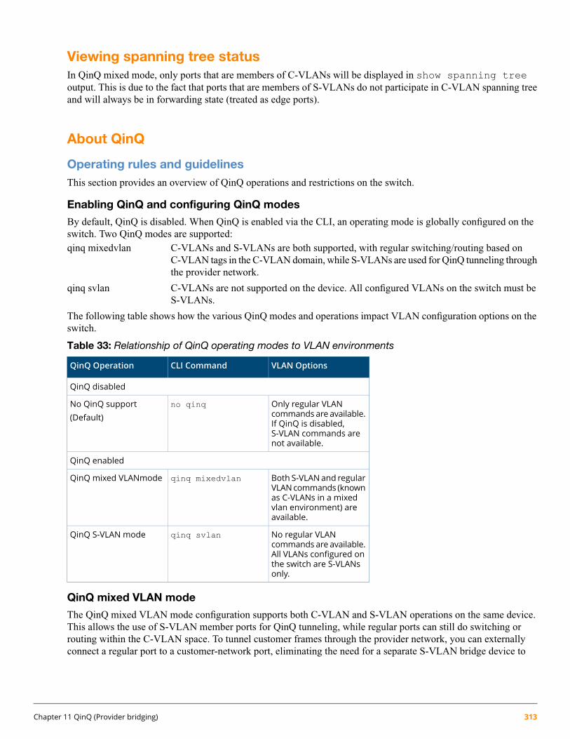
Viewing spanning tree statusIn QinQ mixed mode, only ports that are members of C-VLANs will be displayed in show spanning treeoutput. This is due to the fact that ports that are members of S-VLANs do not participate in C-VLAN spanning treeand will always be in forwarding state (treated as edge ports).
About QinQ
Operating rules and guidelinesThis section provides an overview of QinQ operations and restrictions on the switch.
Enabling QinQ and configuring QinQ modes
By default, QinQ is disabled. When QinQ is enabled via the CLI, an operating mode is globally configured on theswitch. Two QinQ modes are supported:qinq mixedvlan C-VLANs and S-VLANs are both supported, with regular switching/routing based on
C-VLAN tags in the C-VLAN domain, while S-VLANs are used for QinQ tunneling throughthe provider network.
qinq svlan C-VLANs are not supported on the device. All configured VLANs on the switch must beS-VLANs.
The following table shows how the various QinQ modes and operations impact VLAN configuration options on theswitch.
Table 33: Relationship of QinQ operating modes to VLAN environments
VLAN OptionsCLI CommandQinQ Operation
QinQ disabled
Only regular VLANcommands are available.
no qinqNo QinQ support(Default)
If QinQ is disabled,S-VLAN commands arenot available.
QinQ enabled
Both S-VLANand regularVLANcommands (known
qinq mixedvlanQinQ mixed VLANmode
as C-VLANs in a mixedvlan environment) areavailable.
No regular VLANcommands are available.
qinq svlanQinQ S-VLAN mode
All VLANs configured onthe switch are S-VLANsonly.
QinQ mixed VLAN mode
The QinQ mixed VLAN mode configuration supports both C-VLAN and S-VLAN operations on the same device.This allows the use of S-VLAN member ports for QinQ tunneling, while regular ports can still do switching orrouting within the C-VLAN space. To tunnel customer frames through the provider network, you can externallyconnect a regular port to a customer-network port, eliminating the need for a separate S-VLAN bridge device to
Chapter 11 QinQ (Provider bridging) 313

perform such operations. When configuring VLANs on a mixed VLAN mode device, a separate svlan vidcommand is used to distinguish the S-VLAN type from regular VLANs.
The main advantage for QinQ mixed VLAN mode is that users do not have to dedicate the entire switch as a QinQaccess switch. For a high density chassis switch such as the 5400zl, customers can use regular ports for normal LANswitching, while S-VLAN member ports can be configured to access the QinQ provider network (see Figure 57(page 302)). There are some additional restrictions in mixed-VLAN mode.
Figure 64: switch in mixed-VLAN mode
Configuring VLANs
• A VLAN created on a QinQ mixed VLAN mode device can be either a regular VLAN (C-VLAN) or a tunnelVLAN (S-VLAN). C-VLANs have no mapping/relation to the S-VLANs on the device.
• VLANs created on a QinQ S-VLAN mode device can be S-VLANs only. S-VLANs provide QinQ tunnelingof customer frames and behave like a port-based/s-tagged interface.
QinQ and duplicate VIDs
Duplicate VID's for c-tagged and s-tagged VLANs (for example, C-VID=100; S-VID=100) are allowed in certaincases. Customer-network ports are essentially S-VLAN ports: they simply read the C-tags in the customer frame toinsert them into the appropriate untagged S-VLAN for that port. Once this double-tagging occurs, frames areforwarded based on the S-VLAN tag only, while the C-VLAN tag remains shielded during data transmission.
314 HPE ArubaOS-Switch Advanced Traffic Management Guide for WC.16.02
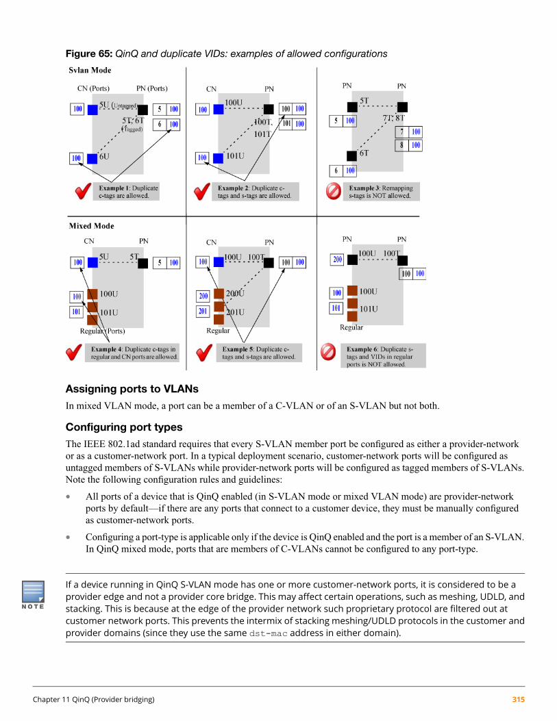
Figure 65: QinQ and duplicate VIDs: examples of allowed configurations
Assigning ports to VLANs
In mixed VLAN mode, a port can be a member of a C-VLAN or of an S-VLAN but not both.
Configuring port types
The IEEE 802.1ad standard requires that every S-VLAN member port be configured as either a provider-networkor as a customer-network port. In a typical deployment scenario, customer-network ports will be configured asuntagged members of S-VLANs while provider-network ports will be configured as tagged members of S-VLANs.Note the following configuration rules and guidelines:
• All ports of a device that is QinQ enabled (in S-VLAN mode or mixed VLAN mode) are provider-networkports by default—if there are any ports that connect to a customer device, they must be manually configuredas customer-network ports.
• Configuring a port-type is applicable only if the device is QinQ enabled and the port is a member of an S-VLAN.In QinQ mixed mode, ports that are members of C-VLANs cannot be configured to any port-type.
If a device running in QinQ S-VLAN mode has one or more customer-network ports, it is considered to be aprovider edge and not a provider core bridge. This may affect certain operations, such as meshing, UDLD, andstacking. This is because at the edge of the provider network such proprietary protocol are filtered out atcustomer network ports. This prevents the intermix of stacking meshing/UDLD protocols in the customer andprovider domains (since they use the same dst-mac address in either domain).
Chapter 11 QinQ (Provider bridging) 315
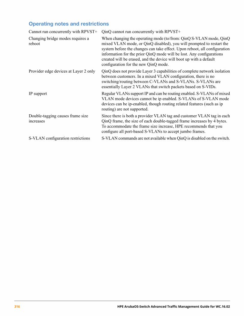
Operating notes and restrictionsCannot run concurrently with RPVST+ QinQ cannot run concurrently with RPVST+
Changing bridge modes requires areboot
When changing the operating mode (to/from: QinQ S-VLAN mode, QinQmixed VLAN mode, or QinQ disabled), you will prompted to restart thesystem before the changes can take effect. Upon reboot, all configurationinformation for the prior QinQ mode will be lost. Any configurationscreated will be erased, and the device will boot up with a defaultconfiguration for the new QinQ mode.
Provider edge devices at Layer 2 only QinQ does not provide Layer 3 capabilities of complete network isolationbetween customers. In a mixed VLAN configuration, there is noswitching/routing between C-VLANs and S-VLANs. S-VLANs areessentially Layer 2 VLANs that switch packets based on S-VIDs.
IP support Regular VLANs support IP and can be routing enabled. S-VLANs of mixedVLAN mode devices cannot be ip enabled. S-VLANs of S-VLAN modedevices can be ip-enabled, though routing related features (such as iprouting) are not supported.
Double-tagging causes frame sizeincreases
Since there is both a provider VLAN tag and customer VLAN tag in eachQinQ frame, the size of each double-tagged frame increases by 4 bytes.To accommodate the frame size increase, HPE recommends that youconfigure all port-based S-VLANs to accept jumbo frames.
S-VLAN configuration restrictions S-VLAN commands are not available when QinQ is disabled on the switch.
316 HPE ArubaOS-Switch Advanced Traffic Management Guide for WC.16.02

VLAN configuration restrictions inmixed VLAN mode
Both C-VLANs and S-VLANs can be configured on the switch. In amixed mode device, the default VLAN is always a C-VLAN.
•
• VLAN types cannot be updated dynamically. A VLAN can beclassified only as an S-VLAN or a C-VLAN at the time its created.Once created, the VLAN cannot be moved between being a C-VLANand an S-VLAN. If a VID that was initially created as a regular VLANneeds to be used for an S-VLAN, the VID must be deleted andre-created as an S-VLAN.
• If a VLAN being configured as an S-VLAN already exists as a GVRPC-VLAN or a static C-VLAN on the switch, the S-VLAN creation isblocked. Similarly, a C-VLAN creation is blocked if the same VIDexists as a static S-VLAN on the device.
• S-VLANs in a mixed vlan device cannot be configured as avoice-VLAN, primary-VLAN, or management-VLAN.
• S-VLANs cannot be configured with ip-layer functionality, exceptfor ip-acls.
VLAN configuration restrictions inS-VLAN mode
Only S-VLANs are supported—the keyword on all vlan-relatedcommand syntax changes from vlan to svlan.
•
• Routing related features such as ip-routing, RIP, OSPF, PIM, andVRRP are not supported in S-VLAN mode.
Port-based restrictions In QinQ mixed VLAN mode, a port must be explicitly GVRP-disabledbefore it can be assigned to the S-VLAN space.
•
• In QinQ mixed VLAN mode, only ports that are members ofS-VLANs can be configured as customer network or provider networkports; ports that are members of C-VLANs cannot be configured toany port-type.
• QinQ mixed VLAN mode devices cannot be connected in an S-VLANmesh topology. This is because STP cannot be run in the S-VLANspace, and so a mesh topology (or the presence of any redundant links)would result in loops.
• A port can either be a member of S-VLANs or C-VLANs only, butnot a combination of both.
• A port cannot be configured as a Customer-Edge as specified inSection 12.13.3 of the IEEE 802.1ad specification. In the currentsoftware release, such C-tagged interfaces are not supported—onlyport-based/S-tagged interfaces are supported.
• Moving ports between C-VLANs and S-VLANs may cause conflicts.For example, if a port has any mirroring/monitoring sessions set up,they will not be allowed to change VLAN domains until these sessionsare re-configured.
Interoperating with other vendor devices When enabling QinQ, you can configure a unique tpid value, such as0x8100, to allow the device to interoperate with devices that require this
Chapter 11 QinQ (Provider bridging) 317

value for the inner and outer VLAN-tag. If the provider tag-type isconfigured as 0x8100, then:
• Customer-network ports cannot be configured as tagged-S-VLANmembers
• Tagged-S-VLAN members cannot be configured as customer-networkports.
Configuring QinQ with other networkprotocols
The networks for both the customer and provider can be complex. Forinformation on how QinQ may impact other network protocols (such asspanning tree, LLDP, and GVRP), see Figure 64 (page 314)
Changing QinQ modesChanging QinQ modes (or disabling QinQ operations) will result in the current configuration being erased. See thefollowing Caution for details.
Configuring the switch to operate in a different bridge mode requires a reboot to take effect. Upon reboot, allconfiguration information for the prior QinQmode is lost. Any configurations created under the existing QinQmode is erased, and the device boots up with a default configuration for the new QinQ mode.
For information on the effect of the different QinQ modes on switch protocols and operations, see Table 34 (page 319).
Effects of QinQ on other switch featuresPer the IEEE standards, protocols such as STP and GVRP are assigned separate addresses for customer networksand provider networks, ensuring that QinQ has no impact on their operations. Bridge Protocol Data Units (BPDUs)that need to be tunneled through the provider network are treated as normal multicast frames at the provider bridgeand forwarded out.
However, other protocols use common addresses for both customer and provider networks, and so are not supportedwhen QinQ is enabled on the switch. Similarly, proprietary features such as meshing, discovery, UDLD, andloop-protect do not provide tunneling support. In such cases, where provider networks could run an instance of thesame protocol as a customer could run local to their site, these frames are dropped at the customer-network ports ofthe provider bridge.
The IEEE standards group is devising new addressing schemes that may support additional QinQ tunnelingoperations. Check the latest product release notes for implementation updates as they apply to switches.
When QinQ is not enabled (the default setting), there are no impacts to the switch's normal operations. The followingtable shows the impacts of QinQ on the operation of switch protocols and features based on the QinQ mode that isconfigured as QinQ mixed VLAN mode (C-VLANs and S-VLANs are allowed) or QinQ S-VLAN mode (S-VLANsonly).
318 HPE ArubaOS-Switch Advanced Traffic Management Guide for WC.16.02
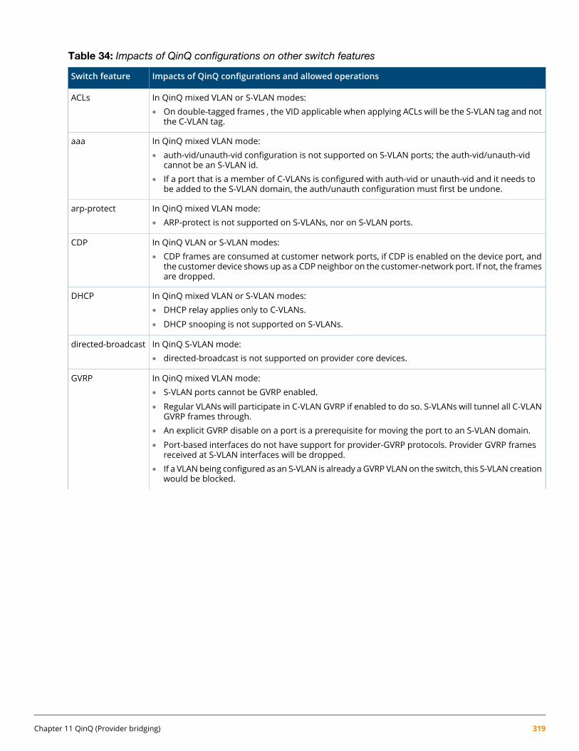
Table 34: Impacts of QinQ configurations on other switch features
Impacts of QinQ configurations and allowed operationsSwitch feature
In QinQ mixed VLAN or S-VLAN modes:• On double-tagged frames , the VID applicable when applying ACLs will be the S-VLAN tag and not
the C-VLAN tag.
ACLs
In QinQ mixed VLAN mode:aaa• auth-vid/unauth-vid configuration is not supported on S-VLAN ports; the auth-vid/unauth-vid
cannot be an S-VLAN id.• If a port that is a member of C-VLANs is configured with auth-vid or unauth-vid and it needs to
be added to the S-VLAN domain, the auth/unauth configuration must first be undone.
In QinQ mixed VLAN mode:• ARP-protect is not supported on S-VLANs, nor on S-VLAN ports.
arp-protect
In QinQ VLAN or S-VLAN modes:• CDP frames are consumed at customer network ports, if CDP is enabled on the device port, and
the customer device shows up as a CDP neighbor on the customer-network port. If not, the framesare dropped.
CDP
In QinQ mixed VLAN or S-VLAN modes:DHCP• DHCP relay applies only to C-VLANs.
• DHCP snooping is not supported on S-VLANs.
In QinQ S-VLAN mode:• directed-broadcast is not supported on provider core devices.
directed-broadcast
In QinQ mixed VLAN mode:GVRP• S-VLAN ports cannot be GVRP enabled.
• Regular VLANs will participate in C-VLAN GVRP if enabled to do so. S-VLANs will tunnel all C-VLANGVRP frames through.
• An explicit GVRP disable on a port is a prerequisite for moving the port to an S-VLAN domain.
• Port-based interfaces do not have support for provider-GVRP protocols. Provider GVRP framesreceived at S-VLAN interfaces will be dropped.
• If a VLANbeing configured as an S-VLAN is already aGVRP VLANon the switch, this S-VLAN creationwould be blocked.
Chapter 11 QinQ (Provider bridging) 319

Table 34: Impacts of QinQ configurations on other switch features (continued)
Impacts of QinQ configurations and allowed operationsSwitch feature
In QinQ S-VLAN mode:• GVRP is supported on S-VLAN ports if the qinq mode is S-VLAN.
In QinQ mixed VLAN mode:• IGMP-proxy cannot be configured on S-VLANs.
In QinQ S-VLAN mode:• IGMP-proxy is not supported.
igmp-proxy
In QinQ mixed VLAN mode:• IPv6 features are not supported on S-VLANs.
IPv6
In QinQ mixed VLAN mode:• ip-recv-mac cannot be configured on S-VLANs.
In QinQ S-VLANmode:• ip-recv-mac is not supported.
ip-recv-mac
In QinQ mixed VLAN or S-VLAN modes:• No change in operations. HPE recommends to jumbo-enable all S-VLANs used for customer data
tunneling to support the addition of the extra S-tag in each frame.
Jumbo
In QinQ mixed VLAN mode:LACP/ Port Trunks• Dynamic-LACP is not supported on S-VLAN ports: LACP manual trunks alone are supported. The
new trunk will be a member of C-VLANs (port types are not applicable).• If two ports are added to a trunk, the resultant trunk will be a member of the default-vlan (vid-1)
which is always a C-VLAN. The trunk can subsequently be manually assigned to an S-VLAN.• Port-type and VLAN configurations are not mapped. If the port-type is updated through CLI or
SNMP and the port is subsequentlymoved from the C-VLAN space to the S-VLAN space then backagain, the last configured port-type is retained through each move.
In QinQ S-VLAN mode:• On S-VLAN bridges, both manual and dynamic LACP trunks are supported. HPE does not
recommend that you configure dynamic trunks on customer ports because they cannot becomedynamicmembers of S-VLANs (there is no provider-gvrp for a dynamic trunk to become amemberof S-VLANs.)
• A newly formed trunk will by default be of type provider-network. When the trunk is manuallyassigned to an S-VLAN for the first time after being created, the port-type is provider-network.
In QinQ mixed VLAN mode:Layer 3 Protocols(IP, IP+, DHCP, ARP, • There is no IP layer functionality on S-VLANs.IGMP Layer 3,Layer 3 ACLs) • No change in IP layer functionality on regular C-VLANs.
• S-VLANs cannot be configured as RIP, OSPF, PIM, or VRRP interfaces.
In QinQ S-VLAN mode:• S-VLANs can be ip enabled.
• IP routing is not supported.
In QinQ mixed VLAN or S-VLAN modes:LLDP• LLDP is supported on the device (in both qinqmodes). However, there is no provision for tunneling
customer LLDP BPDUs through the provider-network.• LLDP BPDUs received from a customer's network will be consumed at the customer-network
ports of a provider device and the customer devicewill be displayed as an LLDP neighbor. Similarly
320 HPE ArubaOS-Switch Advanced Traffic Management Guide for WC.16.02

Table 34: Impacts of QinQ configurations on other switch features (continued)
Impacts of QinQ configurations and allowed operationsSwitch feature
the provider network device will show up as a neighbor on the customer's network if thecustomer-network ports send out LLDP advertisements.
In QinQ S-VLAN mode:• Equal cost multi-path (ECMP) is not supported on provider core devices.
load-sharing
In QinQ mixed VLAN mode:• The management VLAN cannot be an S-VLAN.
managementVLAN
In QinQ mixed VLAN mode:• Meshing is not supported on the device.
In QinQ S-VLAN mode:
Meshing
• On an all provider-network ports of an S-VLAN bridge, meshing is supported.
• Meshing cannot be enabled on customer-network ports.
In QinQ mixed VLAN mode:Mirroring/Monitoring• Remote mirroring is not supported on S-VLANs.
• Cannot monitor a VLAN with mirror ports in the other VLAN domain. That is, an S-VLAN or anS-VLAN port cannot be monitored using a C-VLAN port as its mirror, and vice-versa.
• Whenaport ismoved from the S-VLAN space to the C-VLAN space (or vice versa), allmirror/monitorsessions on the port must be unconfigured before the move will be allowed.
In QinQ S-VLAN mode:• Multicast routing is not supported on provider core devices.
multicast-routing
In QinQ mixed VLAN or S-VLAN modes:• HPE does not recommend that you enable DSCP on S-VLANs used for tunneling as the customer
IP-pkt will be modified in the S-VLAN space.
QoS
In QinQ S-VLAN mode:• Routing is not supported on provider core devices.
Routing
In QinQ mixed VLAN or S-VLAN modes:• source-binding cannot be configured on S-VLANs.
source-binding
In QinQ S-VLAN mode:• source-route is not supported on provider core devices.
source-route
In QinQ mixed VLAN mode:Spanning Tree• Customer (C-VLAN) spanning tree is supported. All C-VLAN ports will receive/transmit customer
STP BPDUs and participate in regular VLAN spanning tree as usual.• When customer STP BPDUs are received at S-VLAN ports on the switch, they will be flooded out
of the other ports on the S-VLAN. All such frames will be tunneled through the S-VLAN tunnelunscathed.
• Provider (S-VLAN) spanning tree is not supported on the switch. If S-VLAN STP frames are receivedon any S-VLAN enabled ports, they will be re-forwarded out of the other ports on the S-VLAN.
• STP configuration on S-VLAN ports is not supported.
• If a port that is a member of C-VLANs is moved into being a member of S-VLANs, the port would,by default, tunnel customer STP BPDUs.
Chapter 11 QinQ (Provider bridging) 321

Table 34: Impacts of QinQ configurations on other switch features (continued)
Impacts of QinQ configurations and allowed operationsSwitch feature
• If a C-VLANport has been configuredwith any non-default STP parameters (such as admin-edge,auto-edge, and bpdu-protect) and is then moved into an S-VLAN, the port will be put into aforwarding state regardless of the STP configurations done when the port was a member of theC-VLAN.
• MSTP instances cannot include S-VLANs.
In QinQ S-VLAN mode:• Provider (S-VLAN) spanning tree is supported—bothprovider-networkports and customer-network
ports will receive/transmit provider STP BPDUs.• Customer (VLAN) spanning tree tunneling is supported on S-VLAN interfaces—customer-network
or provider-network ports will tunnel customer STP BPDUs through the appropriate S-VLAN.
In QinQ mixed VLAN mode:• Stacking is supported only on C-VLANs. The device does not advertise itself (using the stack
discovery protocol) in the S-VLAN space.In QinQ S-VLAN mode:• Configuring QinQ with S-VLANs in a switch is not supported. Stacking discovery protocol frames
will not be sent out of customer-network ports; similarly, any stacking discovery protocol framesreceived on customer-network ports will be dropped.
Stacking (3800switches)
In QinQ mixed vlan or S-VLAN modes:UDLD• UDLD frames received on udld-disabled customer network ports will be dropped. However, if the
customer-network port is udld-enabled, it can peer with a customer device.• UDLD frames received on udld-disabled provider network ports will be re-forwarded out of other
udld-disabled provider network ports on the same VLAN.• UDLD re-forwarding in the C-VLAN space (QinQ disabled or mixed VLAN mode) will remain
unaltered.
In QinQ S-VLAN mode:• udp-bcast-forward is not supported on provider core devices.
udp-bcast-forward
In QinQ mixed VLAN mode:unknown-vlans• GVRP (learn and disabled modes) not supported on S-VLAN ports.
• A C-VLAN port that has GVRP enabled will need to disable it before it can be added to S-VLANs.
In QinQ mixed VLAN mode:• S-VLANs cannot be configured as voice-VLANs.
Voice VLANs
In QinQ mixed VLAN or S-VLAN modes:• VRRP is not supported on S-VLANs.
VRRP
322 HPE ArubaOS-Switch Advanced Traffic Management Guide for WC.16.02
Chapter 12
Classifier-based software configuration
All commands previously in the Summary of commands table are indexed under the entry Command syntax.
IntroductionClassifier-based service policies are designed to work with existing globally configured switch-wide and port-widesettings by allowing you to select a subset of:
• Traffic sent to or from certain ports
• VLAN traffic
Once the traffic is selected, you can further manage it.
Classifier-based service policies take precedence over, and may override, globally configured settings. These policiesprovide greater control for managing network traffic. Using multiple match criteria, you can finely select and definethe classes of traffic that you want to manage. You can then use policy actions to determine how the selected trafficis handled.
Classes can be based on IPv4 or IPv6 addresses (which you specify in the policy).
When using an HPE AllianceONE Extended Services zl Module that supports Transparent Mode, you can alsoclassify traffic based on zones.
Configuring a traffic classTo configure a traffic class to be used in one or more policies, follow these steps:
1. Enter the class command from the global configuration context.
Context: Global configuration
Syntax:[no] class [ ipv4 | ipv6 ] classname
Defines a traffic class and specifies whether a policy is to be applied to IPv4 or IPv6 packets, whereclassname is a text string (64 characters maximum).
After you enter the class command, you enter the class configuration context to specify matchcriteria. A traffic class contains a series of match and ignore commands, which specify thecriteria used to classify packets.
The no form of the command removes the existing class
2. Enter one or more match or ignore commands from the traffic class configuration context to filter trafficand determine the packets on which policy actions will be performed.
Context: Class configuration
Chapter 12 Classifier-based software configuration 323

Syntax:[no] [seq—number] [ match | ignore ] igmp source—address destination—address [igmp—type ] [ ip—dscp codepoint ] [ precedence precedence—value ] [ tos tos—value] [ vlan vlan—id ]seq-number (Optional) Sequentially orders the match/ignore statements that you
enter in a traffic class configuration. Packets are checked by thestatements in numerical order.
Default: Match/ignore statements are numbered in increments of 10,starting at 10. To re-number the match/ignore statements in a classconfiguration, use the resequence command.
match | ignore Defines the classifier criteria used to determine which packets belongto the traffic class.
If a packet matches a match criterion, it becomes a member of thetraffic class and is forwarded according to the actions configured withthe policy command. If a packet matches an ignore criterion, nopolicy action is performed on the packet. You can enter one or morematch/ignore statements in a traffic class.
To remove a match/ignore statement from a class configuration, enterthe no seq-number command or the complete form of a nomatch or no ignore command.
ip-protocol Specifies an IP protocol to be matched in packet fields of IPv4 orIPv6 traffic, where ip-protocol is one of the values describedbelow.
When entering a match/ignore command in an IPv4 or IPv6 class,enter ? to display a list of valid ip-protocol entries.
• In an IPv4 class, you can enter any of the following IPv4 protocolmatch criteria:
ahespgreicmp*
igmp*
ipip-in-ipipv6–in-ipospfpimsctptcp*
udp*
vrrp
To specify an IPv4 protocol as match criteria, you can also enterits protocol number. Valid values are from 0 to 255.
For example, 8 means Exterior Gateway Protocol; 121 meansSimple Message Protocol. For a list of IPv4 protocol numbers
*. For IPv4 ICMP, IGMP, TCP, and UDP packets, you can enter additional match criteria.
324 HPE ArubaOS-Switch Advanced Traffic Management Guide for WC.16.02
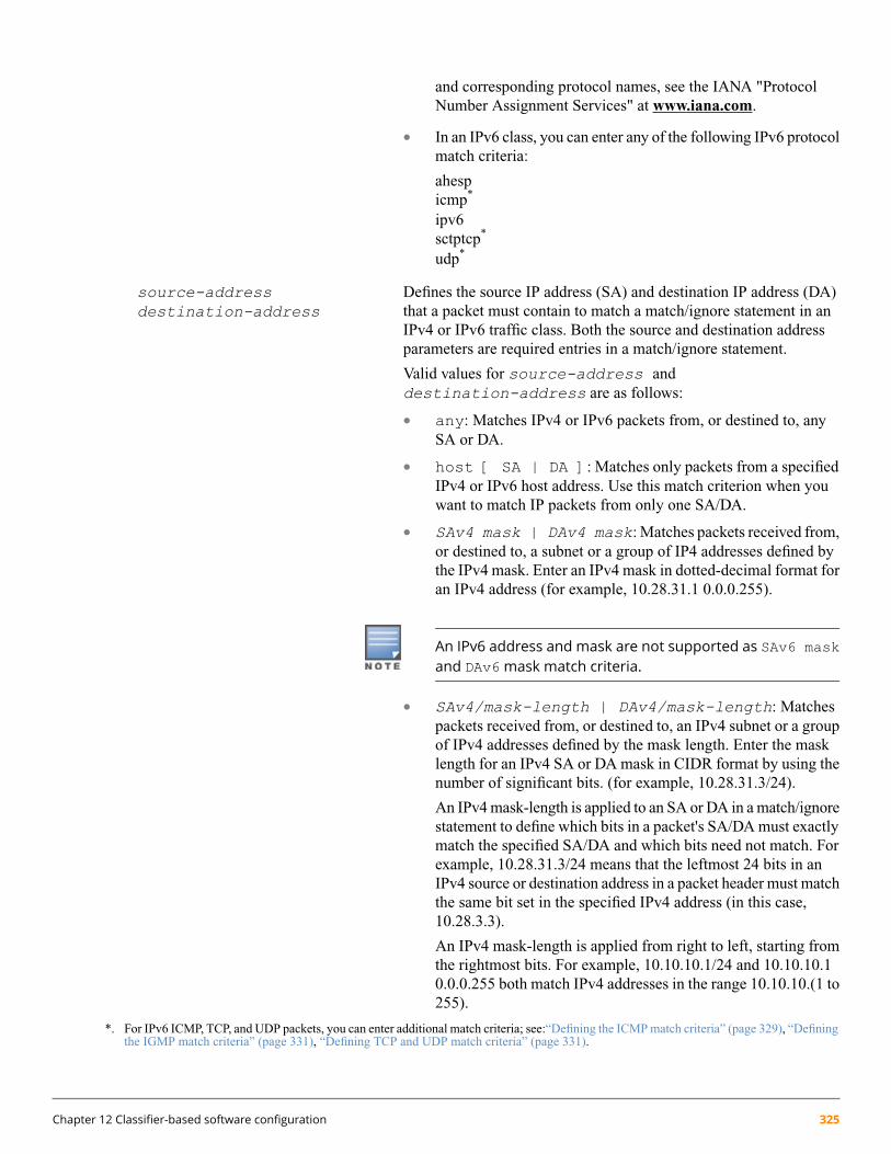
and corresponding protocol names, see the IANA "ProtocolNumber Assignment Services" at www.iana.com.
• In an IPv6 class, you can enter any of the following IPv6 protocolmatch criteria:
ahespicmp*
ipv6sctptcp*
udp*
source-addressdestination-address
Defines the source IP address (SA) and destination IP address (DA)that a packet must contain to match a match/ignore statement in anIPv4 or IPv6 traffic class. Both the source and destination addressparameters are required entries in a match/ignore statement.
Valid values for source-address anddestination-address are as follows:
• any: Matches IPv4 or IPv6 packets from, or destined to, anySA or DA.
• host [ SA | DA ]: Matches only packets from a specifiedIPv4 or IPv6 host address. Use this match criterion when youwant to match IP packets from only one SA/DA.
• SAv4 mask | DAv4 mask: Matches packets received from,or destined to, a subnet or a group of IP4 addresses defined bythe IPv4 mask. Enter an IPv4 mask in dotted-decimal format foran IPv4 address (for example, 10.28.31.1 0.0.0.255).
An IPv6 address and mask are not supported as SAv6 maskand DAv6mask match criteria.
• SAv4/mask-length | DAv4/mask-length: Matchespackets received from, or destined to, an IPv4 subnet or a groupof IPv4 addresses defined by the mask length. Enter the masklength for an IPv4 SA or DA mask in CIDR format by using thenumber of significant bits. (for example, 10.28.31.3/24).
An IPv4 mask-length is applied to an SA or DA in a match/ignorestatement to define which bits in a packet's SA/DA must exactlymatch the specified SA/DA and which bits need not match. Forexample, 10.28.31.3/24 means that the leftmost 24 bits in anIPv4 source or destination address in a packet header must matchthe same bit set in the specified IPv4 address (in this case,10.28.3.3).
An IPv4 mask-length is applied from right to left, starting fromthe rightmost bits. For example, 10.10.10.1/24 and 10.10.10.10.0.0.255 both match IPv4 addresses in the range 10.10.10.(1 to255).
*. For IPv6 ICMP, TCP, and UDP packets, you can enter additional match criteria; see:“Defining the ICMP match criteria” (page 329), “Definingthe IGMP match criteria” (page 331), “Defining TCP and UDP match criteria” (page 331).
Chapter 12 Classifier-based software configuration 325

Specifying a group of non-contiguous IP source addressesmay require more than one match/ignore statement.
• SAv6/prefix-length | DAv6/prefix-length:Matches packets received from, or destined to, an IPv6 subnetor a group of IPv6 addresses defined by the prefix length. Enterthe prefix length for an IPv6 SA/DA in CIDR format by usingthe number of significant bits; for example:2001:db8:2620:212::01b4/64.
An IPv6 prefix-length is applied to an SA/DA in a match/ignorestatement to define which bits in a packet's SA/DA must exactlymatch the specified SA/DA and which bits need not match. Forexample, 2001:db8:2620:212::01b4/64 means that the leftmost64 bits in a 128-bit IPv6 source or destination address in a packetheader must match the same bit set in the specified IPv6 address(in this case, 2001:db8:2620:212::01b4).
An IPv6 prefix-length is applied from left to right, starting fromthe leftmost bits. For example, 2001:db8::0001:2620:a03:e102:127/64 and 2001:db8::1: 244:17ff:feb6:d37d/64both match IPv6 addresses with a network prefix of2001:db8:0000:0001.
ip-dscp codepoint (Optional) Matches the six-bit DSCP codepoint DSCP codepoint inIPv4 or IPv6 packets to further define match criteria. Valid valuesfor codepoint are one of the following:
• Numeric equivalent of a binary DSCP bit set from 0 (lowpriority) to 63 (high priority)
• ASCII standard name for a binary DSCP bit set:
af11 (001010) af42 (100100)af12 (001100) af43 (100110)af13 (001110) ef(101110) af21 (010010) cs1 (001000)=precedence 1af22 (010100) cs2 (010000)= precedence 2af23 (010110) cs3 (011000)= precedence 3af31 (011010) cs4 (100000)= precedence 4af32 (011100) cs5 (101000)= precedence 5af33 (011110) cs6 (110000)= precedence 6af41 (100010) cs7 (111000) = precedence 7default (000000)
To display a list of valid codepoint entries when you enterip-dscp in a match/ignore statement, enter ?.
The DSCP codepoints are the leftmost six bits of the ToS/TrafficClass byte.
326 HPE ArubaOS-Switch Advanced Traffic Management Guide for WC.16.02

precedence precedence-value (Optional) Matches the three-bit IP precedence value in IPv4 or IPv6packets to further define match criteria. Valid values forprecedence-value are either the numeric value (0 to 7) orcorresponding name of an IP precedence bit set:
0 routine1 priority2 immediate3 flash4 flash-override5 critical6 internet (for internetwork control)7 network (for network control)
To display a list of valid precedence-value entries when youenter precedence in a match/ignore statement, enter ?.
When used as a match criteria, the IP precedence value is appliedto all other criteria configured in thematch/ignore statement. Youcan enter a match/ignore statement either with or without aprecedence-value.
The IP precedence bits are the leftmost three bits of the ToS/TrafficClass byte. The numeric value (0 to 7) of the IP precedence bitscorresponds to the hexadecimal equivalent of the three binary 0 and1 bits in the IP precedence field. For example if the IP precedence-bitbinary values are 1 1 1, the numeric value is 7 (1+2+4). Similarly,if the IP precedence bits are 0 1 0, the numeric value is 2 (0+2+0).
tos tos-value (Optional) Matches the Delay Throughput Reliability (DTR) bit setin the IPv4 Type-of-Service or IPv6 Traffic Class byte to furtherdefine match criteria.
Valid values are the numeric value or corresponding name of the DTRbit set. Some useful values are as follows:
0 — normal2 — max-reliability4 — max-throughput8 — minimize-delay
Default: 0 or normal.
To display a list of valid tos-value entries when you enter tosin a match/ignore statement, enter ?.
When used as a match criteria, the ToS/Traffic Class byte entry isapplied to all other criteria configured in the match/ignorestatement. You can enter a match/ignore statement either withor without a tos-value.
Chapter 12 Classifier-based software configuration 327
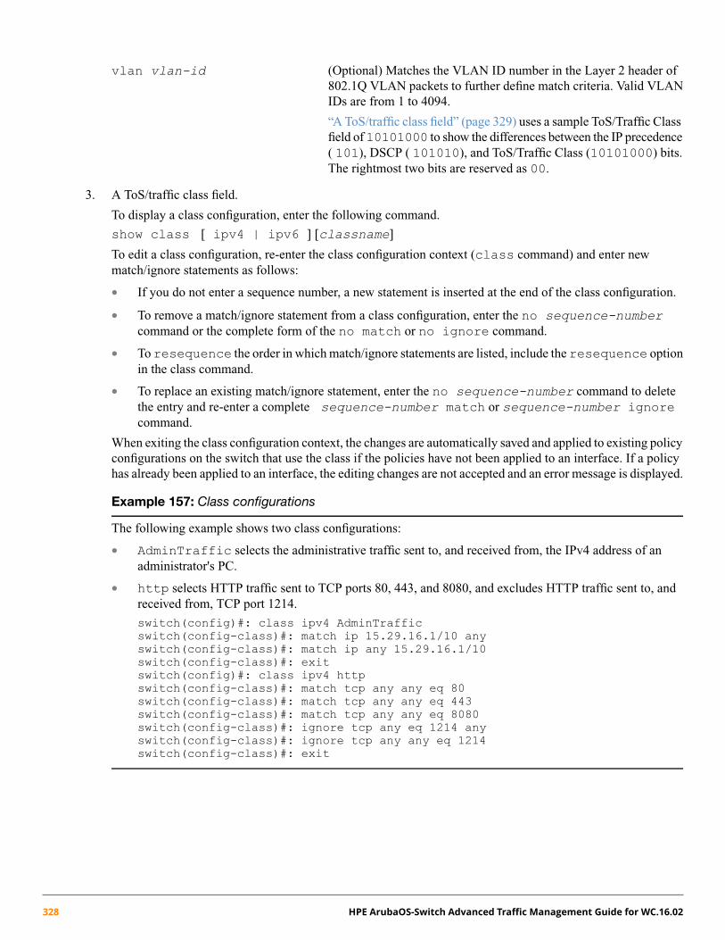
vlan vlan-id (Optional) Matches the VLAN ID number in the Layer 2 header of802.1Q VLAN packets to further define match criteria. Valid VLANIDs are from 1 to 4094.
“A ToS/traffic class field” (page 329) uses a sample ToS/Traffic Classfield of10101000 to show the differences between the IP precedence( 101), DSCP ( 101010), and ToS/Traffic Class (10101000) bits.The rightmost two bits are reserved as 00.
3. A ToS/traffic class field.
To display a class configuration, enter the following command.
show class [ ipv4 | ipv6 ] [classname]
To edit a class configuration, re-enter the class configuration context (class command) and enter newmatch/ignore statements as follows:
• If you do not enter a sequence number, a new statement is inserted at the end of the class configuration.
• To remove a match/ignore statement from a class configuration, enter the no sequence-numbercommand or the complete form of the no match or no ignore command.
• To resequence the order in which match/ignore statements are listed, include the resequence optionin the class command.
• To replace an existing match/ignore statement, enter the no sequence-number command to deletethe entry and re-enter a complete sequence-number match or sequence-number ignorecommand.
When exiting the class configuration context, the changes are automatically saved and applied to existing policyconfigurations on the switch that use the class if the policies have not been applied to an interface. If a policyhas already been applied to an interface, the editing changes are not accepted and an error message is displayed.
Example 157: Class configurations
The following example shows two class configurations:
• AdminTraffic selects the administrative traffic sent to, and received from, the IPv4 address of anadministrator's PC.
• http selects HTTP traffic sent to TCP ports 80, 443, and 8080, and excludes HTTP traffic sent to, andreceived from, TCP port 1214.
switch(config)#: class ipv4 AdminTrafficswitch(config-class)#: match ip 15.29.16.1/10 anyswitch(config-class)#: match ip any 15.29.16.1/10switch(config-class)#: exitswitch(config)#: class ipv4 httpswitch(config-class)#: match tcp any any eq 80switch(config-class)#: match tcp any any eq 443switch(config-class)#: match tcp any any eq 8080switch(config-class)#: ignore tcp any eq 1214 anyswitch(config-class)#: ignore tcp any any eq 1214switch(config-class)#: exit
328 HPE ArubaOS-Switch Advanced Traffic Management Guide for WC.16.02
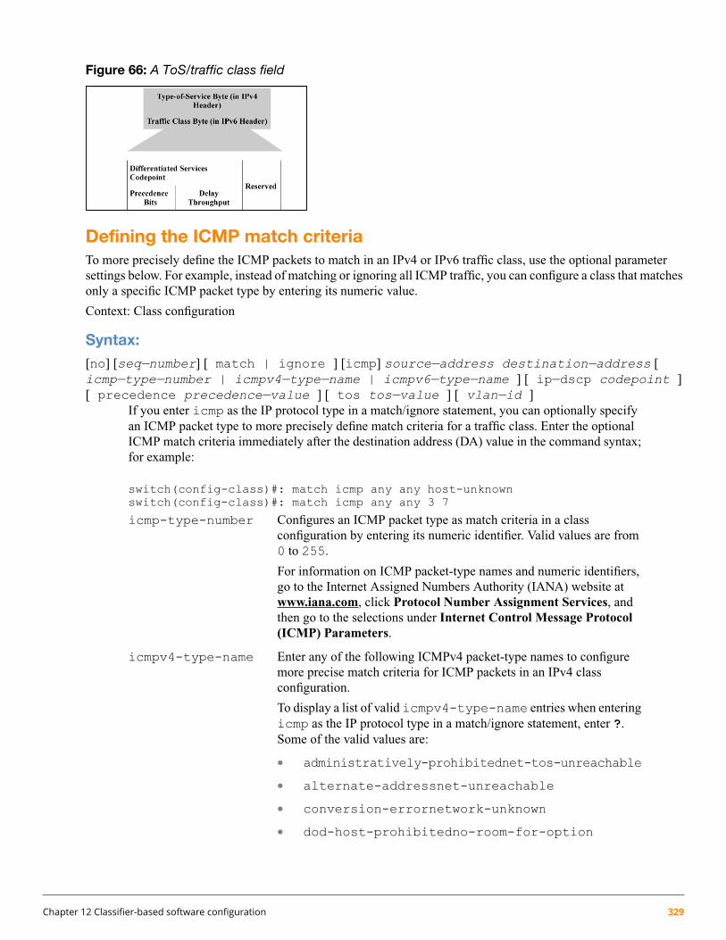
Figure 66: A ToS/traffic class field
Defining the ICMP match criteriaTo more precisely define the ICMP packets to match in an IPv4 or IPv6 traffic class, use the optional parametersettings below. For example, instead of matching or ignoring all ICMP traffic, you can configure a class that matchesonly a specific ICMP packet type by entering its numeric value.
Context: Class configuration
Syntax:[no] [seq—number] [ match | ignore ] [icmp] source—address destination—address [icmp—type—number | icmpv4—type—name | icmpv6—type—name ] [ ip—dscp codepoint ][ precedence precedence—value ] [ tos tos—value ] [ vlan—id ]
If you enter icmp as the IP protocol type in a match/ignore statement, you can optionally specifyan ICMP packet type to more precisely define match criteria for a traffic class. Enter the optionalICMP match criteria immediately after the destination address (DA) value in the command syntax;for example:
switch(config-class)#: match icmp any any host-unknownswitch(config-class)#: match icmp any any 3 7
icmp-type-number Configures an ICMP packet type as match criteria in a classconfiguration by entering its numeric identifier. Valid values are from0 to 255.
For information on ICMP packet-type names and numeric identifiers,go to the Internet Assigned Numbers Authority (IANA) website atwww.iana.com, click Protocol Number Assignment Services, andthen go to the selections under Internet Control Message Protocol(ICMP) Parameters.
icmpv4-type-name Enter any of the following ICMPv4 packet-type names to configuremore precise match criteria for ICMP packets in an IPv4 classconfiguration.
To display a list of valid icmpv4-type-name entries when enteringicmp as the IP protocol type in a match/ignore statement, enter ?.Some of the valid values are:
• administratively-prohibitednet-tos-unreachable
• alternate-addressnet-unreachable
• conversion-errornetwork-unknown
• dod-host-prohibitedno-room-for-option
Chapter 12 Classifier-based software configuration 329

• dod-net-prohibitedoption-missing
• echopacket-too-big
• echo-replyparameter-problem
• general-parameter-problemport-unreachable
• host-isolatedprecedence-unreachable
• host-precedence-unreachableprotocol-unreachable
• host-redirectreassembly-timeout
• host-tos-redirectredirect
• host-tos-unreachablerouter-advertisement
• host-unknownrouter-solicitation
• host-unreachablesource-quench
• information-replysource-route-failed
• information-requesttime-exceeded
• mask-replytimestamp-reply
• mask-requesttimestamp-request
• mobile-redirecttraceroute
• net-redirectttl-exceeded
• net-tos-redirectunreachable
icmpv6-type-name You can also enter any of the following ICMPv6 packet-type namesto configure more precise match criteria for ICMP packets in an IPv6class configuration.
To display a list of valid icmpv6-type-name entries when youenter icmp as the IP protocol type in a match/ignore statement, enter?. Some of the valid values are as follows:
• cert-path-advertisemobile-advertise
• cert-path-solicitmobile-solicit
• destination-unreachablend-na
• echo-replynd-ns
• echo-requestnode-info
• home-agent-replynode-query
• home-agent-requestpacket-too-big
• inv-nd-naparameter-problem
• inv-nd-nsredirect
• mcast-router-advertiserouter-advertisement
• mcast-router-solicitrouter-renum
330 HPE ArubaOS-Switch Advanced Traffic Management Guide for WC.16.02

• mcast-router-terminate router-solicitation
• mld-done time-exceeded
• mld-query ver2-mld-report
• mld-report
Defining the IGMP match criteriaTo more precisely define the IGMP packets to match in an IPv4 traffic class, use the optional parameter settingsdescribed in this section. For example, instead of matching all IGMP traffic, configure a class that matches only aspecific IGMP packet type.
Context: Class configuration
Syntax:[no] [seq—number] [ match | ignore ] igmp source—address destination—address [igmp—type ] [ ip—dscp codepoint ] [ precedence precedence—value ] [ tos tos—value] [ vlan vlan—id ]
If you enter igmp as the IP protocol type in a match/ignore statement, you can optionally specifyan IGMP packet type to more precisely define match criteria for a traffic class. Enter the optionalIGMP match criteria immediately after the destination IP address (DA) value in the command syntax;for example:
switch(config-class)#: match igmp any any host-query
igmp-type Configures an IGMP packet type as match criteria in a class configuration. Someof the valid values for IGMP packet-type names are as follows:
dvmrpmtrace-requesttracehost-querymtrace-replyv2-host-leavehost-reportpimv2-host-reportv3-host-report
To display a list of valid igmp-type entries when you enter igmp as the IPprotocol type in a match/ignore statement, enter ?.
Defining TCP and UDP match criteriaIn a class configuration, you can enter match/ignore statements that more precisely define the TCP or UDP trafficto match in an IPv4 or IPv6 traffic class. For example, enter a port number as a match criterion that specifies one ormore TCP source ports, destination ports, or both.
Context: Class configuration
Syntax:[no] [ seq—number ] [ match | ignore ] tcp | udp source—address [ operatortcp—src—port | udp—src—port ] destination—address [ operator tcp—dest—port[established] [tcp—flag tcp—flag ... ] udp—dest—port ] [ ip—dscp codepoint ][ precedence precedence—value ] [ tos tos—value ][ vlan vlan—id ]
Chapter 12 Classifier-based software configuration 331
If you use TCP or UDP as the IP protocol type in a match/ignore statement, you can optionallyconfigure TCP or UDP source and destination port numbers or ranges of numbers to more preciselydefine match criteria for a traffic class. Enter the optional TCP/UDP match criteria immediatelyafter the source and destination address in the command syntax; for example:
switch(config-class)#: match tcp host 10.20.10.17 eq 23 host 10.20.10.155 establishedswitch(config-class)#: match tcp host 10.10.10.100 host 10.20.10.17 eq telnetswitch(config-class)#: ignore udp 10.30.10.1/24 host 10.20.10.17 range 161 162
operator tcp-src-port |udp-src-port
To specify a TCP or UDP source port number as a matchcriteria, enter a comparison operator from the followinglist with a TCP/UDP port number or well-known portname immediately after the source-address value in thecommand.
Comparison Operators:
• eq tcp/udp-port-numberEqual To matches a packet with the same TCP or UDP source port number astcp/udp-port-number.
• gt tcp/udp-port-numberGreater Than matches any packet with a TCP or UDP source port number greater thantcp/udp-port-number.
• lt tcp/udp-port-numberLess Than matches any packet with a TCP or UDP source port number less thantcp/udp-port-number.
• neq tcp/udp-port-numberNot Equal matches any packet with a TCP or UDP source port number that is not equal totcp/udp-port-number .
• range start-port-numberend-port-number
Matches any packet with a TCP or UDP source port number in the rangestart-port-numbertoend-port-number.
TCP/UDP well-known source-port names and numbersEnter a comparison operator with the source TCP or UDP port number used by the applications youwant to match. Valid port numbers are from 0 to 255. You can also enter well-known TCP or UDPport names as an alternative to the corresponding port number; for example:
• TCP: bgp, dns, ftp, http, imap4, ldap, nntp, pop2, pop3, smtp,ssl, telnet
• UDP: bootpc, bootps, dns, ntp, radius, radius-old, rip, snmp,snmp-trap, tftp
To display a list of valid TCP/UDP source ports, enter ? after you enter an operator.
operator tcp-dest-port established [tcp-flag tcp-flag ... ] | udp-destport
332 HPE ArubaOS-Switch Advanced Traffic Management Guide for WC.16.02

To specify a TCP or UDP destination port number as a match criteria, enter acomparison operatorwith a TCP/UDP port number or well-known port name immediately after the destination-addressvalue in the command.
The optional established and tcp-flag values apply only to TCP destination-port criteria.
TCP/UDP well-known destination-port names and numbersThe same operators, port numbers, and well-known names are supported for TCP/UDPdestination-port match criteria as for TCP/UDP source-port criteria. To display a list of validTCP/UDP destination ports, enter ? after you enter an operator.
established (Optional) Applies only to TCP destination-port match criteriaand matches only on the TCP Acknowledge (ACK) or Reset(RST) flags. The established keyword ignores thesynchronizing packet associated with the establishment of aTCP connection in one direction on a port or VLAN, andmatches all other IP traffic in the opposite direction.
For example, a Telnet connection requires TCP traffic to moveboth ways between a host and the target device. If you configurea match statement for inbound Telnet traffic, policy actions arenormally applied to Telnet traffic in both directions becauseresponses to outbound requests are also matched. However, ifyou enter the established option, inbound Telnet trafficarriving in response to outbound Telnet requests is matched,but inbound Telnet traffic trying to establish a connection isnot matched.
tcp-flag tcp-flag ... (Optional) Applies only to TCP bit settings in packets destinedto a TCP destination port configured as match criteria (withthe tcp-dest-port parameter) and can be one or more ofthe following values:
ack Acknowledge matches TCP packets with the ACK flag.
fin Finish matches TCP packets with the FIN flag.
rst Reset matches TCP packets with the RST bit set.
syn Synchronized matches TCP packets with the SYN flag.
How IPv4 mask bit settings define a match (Example)The following configuration exists:
• A match statement in a class configuration uses an IPv4 source-address/mask-length of 10.38.31.125/21. Themask-length of 21 results in an IPv4 mask of 0.0.7.255. In the second octet of the mask, 7 means that therightmost three bits are on or 1.
• The second octet of the corresponding source address is 31, which means that the rightmost five bits are on or1.
A match occurs when the second octet of the SA in a packet being classified has a value in the range of 24 (binary00011000) to 31 (binary 00001111), as shown in the last row in the following table.
Chapter 12 Classifier-based software configuration 333
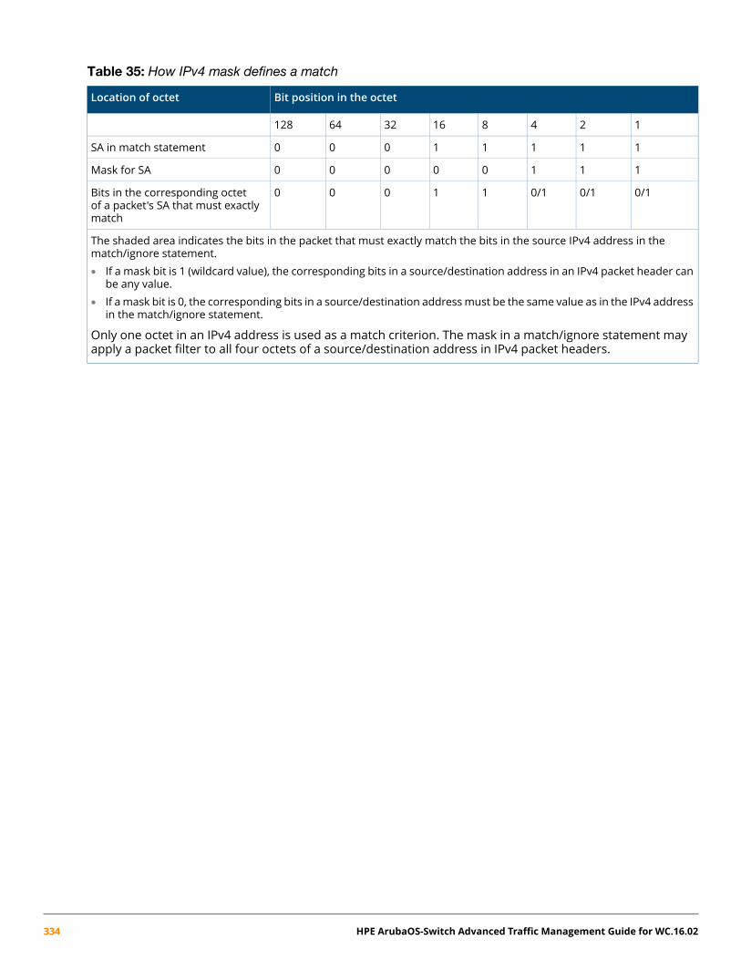
Table 35: How IPv4 mask defines a match
Bit position in the octetLocation of octet
1248163264128
11111000SA in match statement
11100000Mask for SA
0/10/10/111000Bits in the corresponding octetof a packet's SA that must exactlymatch
The shaded area indicates the bits in the packet that must exactly match the bits in the source IPv4 address in thematch/ignore statement.• If a mask bit is 1 (wildcard value), the corresponding bits in a source/destination address in an IPv4 packet header can
be any value.• If a mask bit is 0, the corresponding bits in a source/destination addressmust be the same value as in the IPv4 address
in the match/ignore statement.
Only one octet in an IPv4 address is used as a match criterion. The mask in a match/ignore statement mayapply a packet filter to all four octets of a source/destination address in IPv4 packet headers.
334 HPE ArubaOS-Switch Advanced Traffic Management Guide for WC.16.02

Example 158: How IPv6 mask bit settings define a match
For an example in which an IPv6 prefix-length of 126 is used to select four IPv6 addresses in a match statement,see Figure 67. The specified source IPv6 address is: 2001:DB8:0000:0000:244:17FF:FEB6:D37D. TheIPv6 prefix-length (/126) results in the IPv6 mask: FFFF:FFFF:FFFF:FFFF:FFFF:FFFF:FFFF:FFFC.
Figure 67: Mask for matching four IPv6 devices
To see the on and off settings in the last block of the resulting IPv6 mask that determine the matching IPv6 addresses,see Figure 67. In this mask, all bits except the last two are set to 1 (on) and must be the same in an IPv6 address.The binary equivalent of hexadecimal C is 1100, which allows the last two bits to differ.
Figure 68: How a mask determines four authorized IPv6 manager addresses
To see how the binary equivalent (1100) of the C value in the last block of the resulting IPv6 mask supports fourpossible combinations (D37C, D37D, D37E, and D37F) in the last block of a matching IPv6 address, see Figure 69.Therefore, the IPv6 mask that results from a /126 prefix-length matches inbound traffic from four IPv6-based devices.
Figure 69: How hexadecimal C in an IPv6 mask matches four IPv6 addresses
Chapter 12 Classifier-based software configuration 335
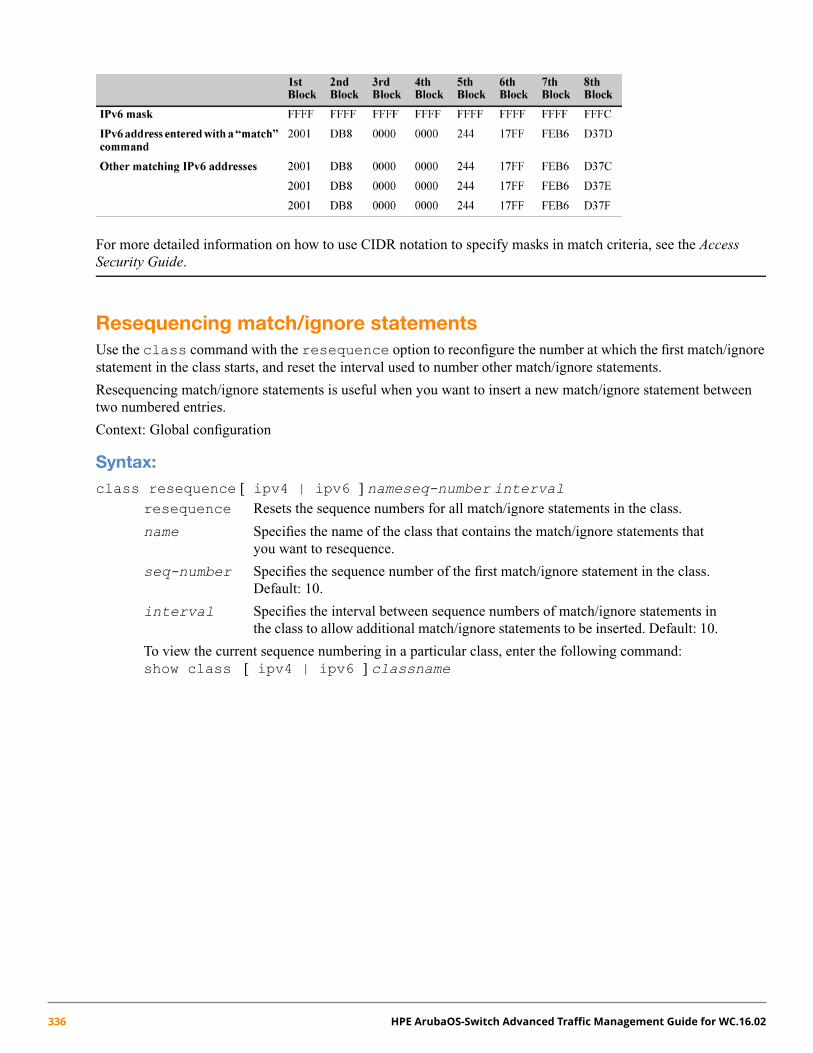
For more detailed information on how to use CIDR notation to specify masks in match criteria, see the AccessSecurity Guide.
Resequencing match/ignore statementsUse the class command with the resequence option to reconfigure the number at which the first match/ignorestatement in the class starts, and reset the interval used to number other match/ignore statements.
Resequencing match/ignore statements is useful when you want to insert a new match/ignore statement betweentwo numbered entries.
Context: Global configuration
Syntax:class resequence [ ipv4 | ipv6 ] nameseq-number interval
resequence Resets the sequence numbers for all match/ignore statements in the class.
name Specifies the name of the class that contains the match/ignore statements thatyou want to resequence.
seq-number Specifies the sequence number of the first match/ignore statement in the class.Default: 10.
interval Specifies the interval between sequence numbers of match/ignore statements inthe class to allow additional match/ignore statements to be inserted. Default: 10.
To view the current sequence numbering in a particular class, enter the following command:show class [ ipv4 | ipv6 ] classname
336 HPE ArubaOS-Switch Advanced Traffic Management Guide for WC.16.02

Example 159: Resequencing a class configuration
The following example shows how to resequence a class configuration so that you can insert new match/ignorestatements between sequentially numbered statements. The resequenced class contains two additional match/ignorestatements and renumbers the criteria with an interval of 10.
Figure 70: Resequencing a class configuration
Creating a service policyIn the classifier-based configuration model, the service policy you create for one or more traffic classes is alwaysrelative to a software feature, such as QoS, port and VLAN mirroring, or PBR. The software feature must supportclass and policy configuration. Each feature supports different actions for managing selected packets.
Policy Based Routing (PBR) is available on the 3800 Series switch and the 5400 series switch which all have v2or higher modules. Any v1 modules will prevent PBR from functioning. PBR is not available on the 3500 and3500yl switches .
PBR is not available on the 2930F switch.
For example, QoS policies support QoS-specific actions, such as rate limiting, 802.1p-priority, IP-precedence, andDSCP-codepoint assignment. Port and VLAN mirroring policies support mirror-destination assignment for matchingpackets. PBR policies support specifying the IP next-hop and IP default next-hop, tunnel ID, or null for matchingpackets.
Chapter 12 Classifier-based software configuration 337

1. To create a service policy that performs feature-specific actions on selected packets, enter the policyfeature-name command from the global configuration context.
Context: Global configuration
Syntax:[no] policy [ qos | mirror | pbr ] [ policy-name]
Defines the name of a service policy and enters the policy configuration context, wherepolicy-name is a text string (64 characters maximum).
A traffic policy consists of one or more actions that are configured for each class of traffic. The configuredactions are executed on packets that match a match statement in a class. No policy action is performed onpackets that match an ignore statement. You can configure multiple classes in a policy.
2. To configure the actions that you want to execute on packets that match the match criteria in a specified class,enter one or more class action commands from the policy configuration context.
Context: Policy configuration
Syntax:[no] [seq-number] class [ ipv4 | ipv6 classname action action-name ] [actionaction-name ...]
Defines the actions to be applied on a pre-configured IPv4 or IPv6 traffic class when a packetmatches the match criteria in the class.
You can enter multiple class-action statements for the same class. The actions supported for a classcommand differ according to the feature-specific policy (for example, QoS or mirroring) configuredwith the policy command in Step 1.
seq-number (Optional) Sequentially orders the class-action statementsin a policy configuration. Actions are executed onmatching packets in numerical order.
Default: Class-action statements are numbered inincrements of 10, starting at 10.
class ipv4|ipv6 classname Defines the preconfigured class on which the actions in aclass-action statement are executed, and specifies whetherthe class consists of IPv4 or IPv6 traffic. The class nameis a text string (64 characters maximum).
You can configure multiple class-action statements to include different classes in a policy. Theexecution of actions is performed in the order in which the class-actions are numerically listed.
action action-name [action action-name ...]Theaction keyword configures the action specified by theaction-name parameter. The actionis executed on any packet that matches the match criteria in the class. The action is not executedon packets that match ignore criteria. You can configure more than one action for a class. Thecomplete no form of the class action command or the no seq-number command removesan action from the policy configuration.
Be sure to enter a class and its associated actions in the precise order in which you want packets tobe checked and handled by class action commands.
338 HPE ArubaOS-Switch Advanced Traffic Management Guide for WC.16.02

3. (Optional) To configure adefault class, enter the default-class command and specify one or more actionsto be executed on packets that are not matched and not ignored.
Context: Policy configuration
Syntax:[no] default-class action action-name [action action-name ...]
Configures a default class to be used to execute one or more actions on packets that are not matchednor ignored in any of the class configurations in a policy. Thedefault-class action commandsupports only the feature-specific commands supported in the class actioncommand.
The default class manages packets that do not match the match or ignore criteria in all classesin a policy, and otherwise would have no actions performed on them.
The default class differs from other classes because it contains no match/ignore statements and usesimplicit match ipv4 any any and match ipv6 any any statements to manage allunmatched packets. If you do not configure a default class, unmatched and ignored packets aretransmitted without an action performed on them.
4. Enter the exit command to exit the policy configuration context.To display a policy configuration, enter the show policy policy-name feature-namecommand where feature-name is a software feature (such as qos, mirror, or pbr) thatsupports classifier-based configuration.
To edit a policy configuration, re-enter the policy context (policy command) and modifyclass-action statements.
To resequence the order in which class-action statements are listed, enter the resequencecommand.
Example 160: A policy configuration
In the following QoS policy configuration, matching HTTP packets are rate limited to 10000 kbps. All unmatchedpackets are managed by the default class, which assigns a slightly higher 802.1p priority (4) and a new DSCPcodepoint (5).
switch(config)#: class ipv4 httpswitch(config-class)#: match tcp any any eq 80switch(config-class)#: match tcp any any eq 8080switch(config-class)#: exitswitch(config)#: policy qos RateLimitPrioritizeSuspectTrafficswitch(policy-qos)#: class ipv4 http action rate-limit kbps 10000switch(policy-qos)#: default-class action priority 4 action dscp 5switch(policy-qos)#: exit
A policy configuration requires a feature-specific policy command to identify the software feature used to manageone or more traffic classes:
• To configure a QoS policy, use the policy qos command as described in the "Quality of Service" chapterin the Advanced Traffic Management Guide.
• To configure a mirroring policy, use the policy mirror command as described in the Management andConfiguration Guide for your switch.
Chapter 12 Classifier-based software configuration 339

Modifying classes in a policyYou can modify the classes and class-action statements in a policy configuration without removing them from thepolicy:
• To modify the match/ignore statements in a class, enter the class-configuration context with the command, andmake the necessary changes by removing or replacing existing statements. To display a class configuration,enter the following command as shown in “Resequencing a class configuration” (page 337):show class [ ipv4 | ipv6 ] classname
When you exit class configuration context, the changes are automatically saved and applied to existing policyconfigurations on the switch that use the class if the policies have not been applied to an interface. If a policyhas already been applied to an interface, the editing changes are not accepted and an error message is displayed.
• To modify the class-action statements in a policy, enter the policy-configuration context with the policyfeature-name policy-name command. To display a policy configuration, enter the following commandas shown in “Resequencing a policy configuration” (page 341):show policy feature-name policy-nameThen do one of the following:
• You can enter a new class-action statement. If you do not enter a sequence number, the new class-actionstatement is inserted at the end of the policy configuration.
• To remove a class-action statement from a policy configuration, enter the no sequence-numbercommand or the complete form of the no class ... action command.
• To resequence the order in which class-action statements are listed, enter the resequencecommand.
• To replace an existing class-action statement, enter the no sequence-number command to delete theentry, and re-enter the following complete command:class [ ipv4 | ipv6 ] classnameaction action-name or default-class action action-name
When exiting the policy-configuration context, the changes are automatically saved and applied to the policyconfiguration if the policy has not been applied to an interface. If the policy has already been applied to an interface,the editing changes are not accepted and an error message is displayed.
Resequencing classes in a policyYou can use the policy command with the resequence option to reconfigure the number at which the firstclass-action statement starts, and reset the interval used to number other class-actions.
Resequencing class-actions is useful when you want to insert a new class-action between two numbered entries.
Context: Global configuration
Syntax:policy resequence name seq-number interval
resequence Resets the sequence numbers for all class-action statements in the policy.
name Specifies the name of the policy that contains the class-action statements thatyou want to resequence.
seq-number Specifies the sequence number of the first class-action-statement in the policy.Default: 10.
340 HPE ArubaOS-Switch Advanced Traffic Management Guide for WC.16.02
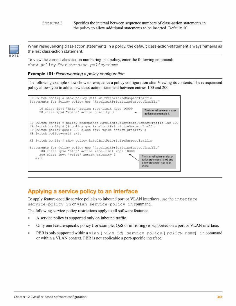
interval Specifies the interval between sequence numbers of class-action statements inthe policy to allow additional statements to be inserted. Default: 10.
When resequencing class-action statements in a policy, the default class-action-statement always remains asthe last class-action statement.
To view the current class-action numbering in a policy, enter the following command:show policy feature-name policy-name
Example 161: Resequencing a policy configuration
The following example shows how to resequence a policy configuration after Viewing its contents. The resequencedpolicy allows you to add a new class-action statement between entries 100 and 200.
Applying a service policy to an interfaceTo apply feature-specific service policies to inbound port or VLAN interfaces, use the interfaceservice-policy in or vlan service-policy in command.
The following service-policy restrictions apply to all software features:
• A service policy is supported only on inbound traffic.
• Only one feature-specific policy (for example, QoS or mirroring) is supported on a port or VLAN interface.
• PBR is only supported within a vlan [vlan-id] service-policy [policy-name] in commandor within a VLAN context. PBR is not applicable a port‐specific interface.
Chapter 12 Classifier-based software configuration 341

Policy Based Routing (PBR) is available on the 3800 Series switch and the 5400 series switch which all havev2 or higher modules. Any v1modules will prevent PBR from functioning. PBR is not available on the 3500or 3500yl switches.
• If you apply a policy to a port or VLAN interface on which a policy of the same type (for example, QoS) isalready configured, an error message is displayed. The new policy does not overwrite the existing one.
Before you can apply a new policy, you must first remove the existing policy with the no interfaceservice-policy in or no vlan service-policy in command.
Because only one policy of each type is supported on a port or VLAN interface, ensure that the policy you want toapply contains all the required classes and actions for your configuration.
If ICMP rate limiting is already configured on a port, a service policy cannot be applied to the port until youdisable the ICMP rate limiting configuration.
To apply a service policy to the port, maintain ICMP rate limiting by configuring a QoS policy in which you addthe necessary match statements for ICMP packets to a class configuration and configure a rate-limit actionfor the class in the policy configuration.
For information on globally configured ICMP, see the Management Configuration Guide for your switch.
To apply a service policy on a port or VLAN interface, enter one of the following commands from the globalconfiguration context.
Context: Global configuration
Syntax:interface port-list service-policy policy-name in
Configures the specified ports with a policy that is applied to inbound traffic on each interface.Separate individual port numbers in a series with a comma; for example, a1, b4, d3. Enter arange of ports by using a dash; for example, a1-a5.
The policy name you enter must be the same as the policy name you configured with the policycommand.
Context: Global configuration
Syntax:vlan vlan-id service-policy policy-name in
Configures a policy on the specified VLAN that is applied to inbound traffic on the VLAN interface.Valid VLAN ID numbers range from 1 to 4094.
The policy name you enter must be the same as the policy name you configured with the policycommand.
342 HPE ArubaOS-Switch Advanced Traffic Management Guide for WC.16.02

Example 162: Applying a QoS policy to a port range and a VLAN interface
The following example shows how to apply a QoS policy to a port range and a VLAN interface:
switch(config)#: interface a4 service-policy RateLimitPrioritizeSuspectTraffic inswitch(config)#: vlan 10 service-policy RateLimitPrioritizeSuspectTraffic in
Checking resource usage
Syntax:show policy resources
After applying service policies to an interface, use the show policy resources command toverify the amount of additional resources used and the amount of resources that are still availableon the switch. Classifier-based service policies (such as QoS or mirroring) share the same hardwareresources with other software features, such as ACLs, virus throttling, management VLAN, globallyconfigured QoS policies, MAC-based mirroring policies, and so on.
Use the displayed information to decide whether to re-prioritize current resource usage byreconfiguring or disabling software features to free the resources reserved for less important features.For a detailed explanation of the information displayed with the show policy resourcescommand, see the Management and Configuration Guide.
Chapter 12 Classifier-based software configuration 343
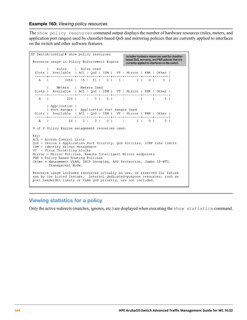
Example 163: Viewing policy resources
The show policy resources command output displays the number of hardware resources (rules, meters, andapplication port ranges) used by classifier-based QoS and mirroring policies that are currently applied to interfaceson the switch and other software features.
Viewing statistics for a policyOnly the active redirects (matches, ignores, etc.) are displayed when executing the show statistics command.
344 HPE ArubaOS-Switch Advanced Traffic Management Guide for WC.16.02
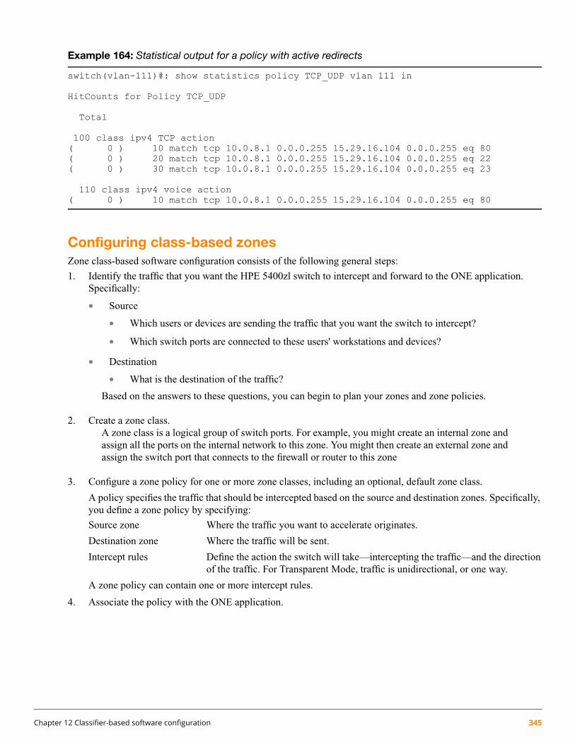
Example 164: Statistical output for a policy with active redirects
switch(vlan-111)#: show statistics policy TCP_UDP vlan 111 in
HitCounts for Policy TCP_UDP
Total
100 class ipv4 TCP action( 0 ) 10 match tcp 10.0.8.1 0.0.0.255 15.29.16.104 0.0.0.255 eq 80( 0 ) 20 match tcp 10.0.8.1 0.0.0.255 15.29.16.104 0.0.0.255 eq 22( 0 ) 30 match tcp 10.0.8.1 0.0.0.255 15.29.16.104 0.0.0.255 eq 23
110 class ipv4 voice action( 0 ) 10 match tcp 10.0.8.1 0.0.0.255 15.29.16.104 0.0.0.255 eq 80
Configuring class-based zonesZone class-based software configuration consists of the following general steps:
1. Identify the traffic that you want the HPE 5400zl switch to intercept and forward to the ONE application.Specifically:
• Source
• Which users or devices are sending the traffic that you want the switch to intercept?
• Which switch ports are connected to these users' workstations and devices?
• Destination
• What is the destination of the traffic?
Based on the answers to these questions, you can begin to plan your zones and zone policies.
2. Create a zone class.A zone class is a logical group of switch ports. For example, you might create an internal zone andassign all the ports on the internal network to this zone. You might then create an external zone andassign the switch port that connects to the firewall or router to this zone
3. Configure a zone policy for one or more zone classes, including an optional, default zone class.
A policy specifies the traffic that should be intercepted based on the source and destination zones. Specifically,you define a zone policy by specifying:
Source zone Where the traffic you want to accelerate originates.
Destination zone Where the traffic will be sent.
Intercept rules Define the action the switch will take—intercepting the traffic—and the directionof the traffic. For Transparent Mode, traffic is unidirectional, or one way.
A zone policy can contain one or more intercept rules.
4. Associate the policy with the ONE application.
Chapter 12 Classifier-based software configuration 345

Creating a zone classTo use Transparent Mode, you create a zone class and use the port-list command to specify the ports that belongto a zone class. By default, the HPE 5400zl switch supports a maximum of 10 zones. Two are createdautomatically—BYPASS and SWITCH_SELF.
• BYPASS—contains the ports that should not be included in your Transparent Mode configuration. That is, theswitch will not intercept traffic sent to or from the ports in the BYPASS zone. By default, all ports on the switchbecome part of the BYPASS zone, until you assign the ports to a different zone.
• SWITCH_SELF—contains only the switch. You cannot add any ports to this zone.
With these two zones, you create eight zones for a total of 10 zones.
Use the following guidelines when assigning ports to zones.
• The switch ports you add to a zone can be in different VLANs.
• Each switch port can belong to only one zone.
• If a port is already associated with a zone, adding the port to another zone removes that port from its existingzone and adds it to the new zone.
• Ports cannot be added to the SWITCH_SELF zone.
You may also need to create a zone for the ONE Application. Consult the HPE Installation and Getting StartedGuide for your ONE application.
The zone classes you configure will be used later in the zone policies you create.
To configure a zone class to be used in one or more policies, follow these steps:
1. Enter the class zone command from the global configuration context.
Context: Global configuration
Syntax:[no] class zone zone name
Defines a zone class, where zone name is a text string (64 characters maximum).
After you enter the class zone command, you enter the class zone configuration context. Fortransparent mode, you can then enter the port-list you want to define for this zone.
2. Enter the port-list command from the class configuration context to determine the ports on which policyactions will be performed.
Context: Class configuration
Syntax:[no] port-list [ethernet] port
Defines the port or ports that are assigned to this zone class. A port may belong to only one zone;if a port is already associated with a zone, adding the port to another zone removes that port fromits exiting zone and moves it to the new zone.
3. Enter the exit command to exit the class configuration context.4. To display all the classes configured, including the zone classes, enter the show class command. To display
a specific zone class configuration, enter the show class zonezone name command.5. To edit a class configuration, re-enter the class configuration context (class command) and enter new port-list
statements as follows:
346 HPE ArubaOS-Switch Advanced Traffic Management Guide for WC.16.02

6. To remove a port from the zone class, enter the no port-list port command.
Zone class configuration examplesThe following example shows several class configurations:
• Ports A10-A24 belong to the internal zone class.
• Port A1 belongs to the external zone class.
Example 165: A zone class configuration
switch(config)#: class zone internalswitch(config-class)#: port-list a10-a24switch(config-class)#: exitswitch(config)#: class zone externalswitch(config-class)#: port-list a1switch(config-class)#: exit
Creating a zone policy1. To create a zone policy that performs zone-specific actions on selected packets, enter the policy zone
policy-name command from the global configuration context.
Context: Global configuration
Syntax:[no] policy zone policy-name
Defines the name of a service policy and enters the policy configuration context, wherepolicy-name is a text string (64 characters maximum). This name should not be the same as azone name.
A zone policy consists of one or more actions that are configured for specific zones.
No action is performed on packets sent to or from ports in the BYPASS zone. By default, ports are assignedto the BYPASS zone unless you explicitly assign them to a different zone.
2. To configure the actions that you want to execute on ports associated with a zone, enter one or more classcommands from the policy configuration context.
Context: Policy configuration
Syntax:[no] [seq-number] class zonesource zone name destination zone name actionintercept unidirectional
Defines the source and destination zones for packets that must be intercepted and forwarded to theONE application.seq-number (Optional) Sequentially orders the class-action statements
in a policy configuration. Actions are executed onmatching packets in numerical order.
source zone name Defines the source zone for packets that must beintercepted and forwarded to the ONE application.
Chapter 12 Classifier-based software configuration 347

destination zone name Defines the destination zone for packets that must beintercepted and forwarded to the ONE application.
action interceptunidirectional
Defines the action as intercept and the flow of traffic asunidirectional (one-way).
Default: Class-action statements are numbered in increments of 10, starting at 10.
The configured actions are executed on packets that arrive on the ports associated with the source zone and aredestined for ports associated with the destination zone.
You cannot configure intercept rules for the BYPASS zone class. As such, traffic to and from the BYPASSzone cannot be intercepted.
3. Enter the exit command to exit the policy configuration context.4. To display a policy configuration, enter the show policy policy-name command.
To edit a policy configuration, re-enter the policy context (policy command) and modify class-actionstatements.
Example 166: Forwarding zone traffic
In the following policy configuration, traffic being sent from the internal zone to the external zone is intercepted,so that it can be forwarded to an application that is running on an HPE AllianceONE Extended Services zl Module.switch(config)#: class zone internalswitch(config-class)#: port-list a10-a24switch(config-class)#: exitswitch(config)#: class zone externalswitch(config-class)#: port-list a1-a4switch(config-class)#: exitswitch(config)#: policy zone Firewallswitch(policy-config)#: class zone internal external action intercept unidirectionalswitch(policy-config)#: exit
Modifying zones and policiesYou can modify the zones and class-action statements in a zone policy configuration without removing them fromthe policy:
• To modify the ports associated with a zone, enter the class zone classname command. Remember thatthe classname you entered is case sensitive. From the class-configuration context, make the necessary changes
348 HPE ArubaOS-Switch Advanced Traffic Management Guide for WC.16.02

by removing or adding ports. (To display a class configuration, enter the show class zone classnamecommand.)
When you exit class configuration context, the changes are automatically saved and applied to existing policyconfigurations on the switch that use the class if the policies have not been applied to a ONE application. If apolicy has already been applied, the editing changes are not accepted, and an error message is displayed.
• To modify the class-action statements in a policy, enter the policy policy-name command. (To displaya policy configuration, enter the show policy policy-name command as shown.) From thepolicy-configuration context, complete one of the following:
• Enter a new class-action statement. If you do not include a sequence number, the new class-action statementis inserted at the end of the policy configuration.
• Remove a class-action statement by entering the no sequence-number command.
• Replace an existing class-action statement by:
• Entering the no sequence-number command to delete the entry.
• Entering a new class zone source zone name destination zone name actionintercept unidirectional command.
When you exit the policy-configuration context, the changes are automatically applied to the policy configurationif the policy has not been applied to an interface. If the policy has already been applied to an interface, the editingchanges are not accepted and an error message is displayed.
Applying a zone policy to a ONE applicationTo apply a zone policy to a ONE Application, you can complete one of the following steps:
• Enter the zone-service-policy command on the HPE 5400zl switch
• Use the ONE application's management interface to apply the zone policies
To apply zone policies through the ONE application, consult the HPE Installation and Getting Started Guide forthat application.
To apply a zone service policy from the switch CLI, enter the following command from the global configurationcontext.
Syntax:[no] zone-service-policy policy-name zone [ enable | disable | update ]bind [Ethernet] logical port appname application name appinstance instancedescription [ fail-action [ bypass | block ]] [ expire [ app-down | permanent| slot-down ]]
policy-name Specifies the name of the policy you configured with the policy command.
enable|disable|update Makes the policy active, inactive, or updates options thathave been assigned to a policy.
logical port Specifies the HPE AllianceONE Extended Services zlModule's port 1, using the format slot1.
application name Specifies the name of the ONE application. See theInstallation and Getting Started Guide for the ONEapplication.
Chapter 12 Classifier-based software configuration 349

instance description Specifies the name of the application and the slot in whichit resides. See the Installation and Getting Started Guidefor the ONE application.
fail-action bypass | block Specifies the action the switch will take if the ONEapplication is unavailable). Enter bypass if you wantthe switch to ignore the policies and not intercept trafficif the ONE application is unavailable. Specify block ifyou want the switch to drop traffic that matches yourpolicy criteria if the ONE application is unavailable.
expire Determines if the policy persists if the ONE applicationis down or unavailable.
app-down Specifies if you want the policy to expire if the ONEapplication is unavailable. Specify permanent if youdo not want the policy to ever expire.
slot-down Specifies if you want the policy to expire if the slot inwhich the ONE application is installed is unavailable.
350 HPE ArubaOS-Switch Advanced Traffic Management Guide for WC.16.02
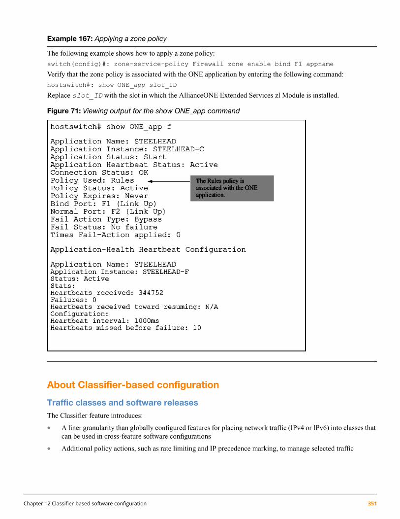
Example 167: Applying a zone policy
The following example shows how to apply a zone policy:
switch(config)#: zone-service-policy Firewall zone enable bind F1 appname
Verify that the zone policy is associated with the ONE application by entering the following command:
hostswitch#: show ONE_app slot_ID
Replace slot_ID with the slot in which the AllianceONE Extended Services zl Module is installed.
Figure 71: Viewing output for the show ONE_app command
About Classifier-based configuration
Traffic classes and software releasesThe Classifier feature introduces:
• A finer granularity than globally configured features for placing network traffic (IPv4 or IPv6) into classes thatcan be used in cross-feature software configurations
• Additional policy actions, such as rate limiting and IP precedence marking, to manage selected traffic
Chapter 12 Classifier-based software configuration 351

• The configuration of service policies for classified traffic with the following software features:
Quality of Service (QoS)•
• Traffic mirroring
• Policy Based Routing (PBR)
• The application of service policies to specific inbound traffic flows on individual port and VLAN interfaces(rather than only on switch-wide or port-wide traffic).
Using CIDR notation for IPv4/IPv6 addressesYou can use CIDR (Classless Inter-Domain Routing) notation to enter an IPv4 mask-length or an IPv6 prefix-lengthwith a source and destination address that are used as match criteria in a match/ignore statement. The switch interpretsthe IP address with CIDR notation to compute the range of corresponding IP source or destination addresses inpacket headers that are considered to be a match for the traffic class.
When the switch uses a match/ignore statement to compare an IP address and corresponding mask/prefix length tothe IP source/destination address carried in a packet, the IPv4 mask-bit settings and IPv6 prefix-bit settings selectpackets in different ways.
• An IPv4 mask length creates a mask in which:
A mask-bit setting set to 0 (off) requires the corresponding bit in a packet's IPv4 source/destination addressto be the same binary value as the mask-bit in the matching IPv4 source/destination address.
•
• A mask-bit setting set to 1 (on) is used as a wildcard and allows the corresponding bit in a packet's IPv4source/destination address to be either binary value (0 or 1).
Table 36: How CIDR notation is used with IPv4 SA/DA match criteria
Range of IPv4 addresses selected by the match criteriaResulting maskIPv4Source/Destinationaddress usedwith CIDRnotation in aMatch/Ignorestatement
The leftmost 15 bits must match; the remaining bits arewildcards.
0.1.255.25510.38.240.125/15
The leftmost 20 bits must match; the remaining bits arewildcards.
0.0.15.25510.38.240.125/20
The leftmost 21 bits must match; the remaining bits arewildcards.
0.0.7.25510.38.240.125/21
The leftmost 24 bits must match; the remaining bits arewildcards.
0.0.0.25510.38.240.125/24
All bits must match.0.0.0.018.38.240.125/32
• An IPv6 prefix-length creates a mask in which:
A mask-bit setting set to 1 (on) requires the corresponding bit in a packet's IPv6 source/destination addressto be the same binary value as the mask-bit in the matching IPv6 source/destination address.
•
• A mask-bit setting set to 0 (off) is used as a wildcard and allows the corresponding bit in a packet's IPv6source/destination address to be either binary value (0 or 1).
352 HPE ArubaOS-Switch Advanced Traffic Management Guide for WC.16.02

Table 37: How CIDR notation is used with IPv6 SA/DA match criteria
Range of IPv6 addresses selected by thematch criteria
Resulting maskIPv6 source/destination address usedwith CIDR notation in a Match/Ignorestatement
The leftmost 64 bits must match; theremaining bits are wildcards.
FFFF:FFFF:FFFF:FFFF::2001:db8:0:7::5/64
The leftmost 72 bits must match; theremaining bits are wildcards.
FFFF:FFFF:FFFF:FFFF:FF00::2001:db8:0:7::5/72
The first 126 bits mst match; the C valuein the mask allows four possible
FFFF:FFFF:FFFF:FFFF:FFFF:FFFF:FFFF:FFFC2001:db8::244:17ff:feb6:d37d/126
combinations (D37C, D37D, D37E, andD37F) in the last block of a matching IPv6address.
All bits must match.FFFF:FFFF:FFFF:FFFF:FFFF:FFFF:FFFF:FFFF2001:db8:0:7:af:e2:c1:5/128
Although IPv4 and IPv6 masks are applied in opposite directions:
◦ An IPv4 mask-length is applied from right to left, starting from the rightmost bits.
◦ An IPv6 prefix-length is applied from left to right, starting from the leftmost bits.
The behavior of IPv4 and IPv6 masks as match criteria and wildcards is the same.
Where to go from here
Classifier-based service policies are designed to work with your existing globally-configured software settings.While existing software features allow you to globally manage all network traffic on a switch or port, classifier-basedservice policies allow you to zoom in on subsets of network traffic to further manage it on a per-port or per-VLANbasis.
You can use the match criteria described in this chapter across software features to configure classes of traffic foruse in feature-specific service policies.
After you decide on the IPv4 and IPv6 network traffic you want to manage, see the Management and ConfigurationGuide for more information about how to configure and use classifier-based quality-of-service and mirroring policies.
Traffic class-based configuration modelTraffic class-based software configuration consists of the following general steps:
1. Determine the inbound traffic you want to manage and how you want to manage it. For example, you may wantto rate limit certain traffic, prioritize it, mirror it, and so on.
2. Classify the traffic that you want to manage by configuring a class, using match and ignore commands. Atraffic class is configured separately from service policies and can be used in various policies.
3. Configure a service policy for one or more address classes, including an optional, default class. A policy consistsof configuration commands executed on specified traffic classes for one of the following software features:
• Quality of Service (policy qos command)
• Port and VLAN mirroring (policy mirror command)
• Policy Based Routing (policy pbr command)
Chapter 12 Classifier-based software configuration 353
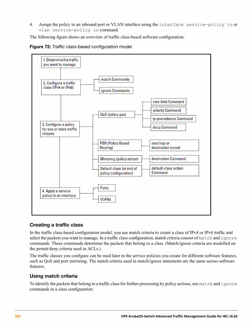
4. Assign the policy to an inbound port or VLAN interface using the interface service-policy in orvlan service-policy in command.
The following figure shows an overview of traffic class-based software configuration:
Figure 72: Traffic class-based configuration model
Creating a traffic class
In the traffic class-based configuration model, you use match criteria to create a class of IPv4 or IPv6 traffic andselect the packets you want to manage. In a traffic class configuration, match criteria consist of match and ignorecommands. These commands determine the packets that belong to a class. (Match/ignore criteria are modelled onthe permit/deny criteria used in ACLs.)
The traffic classes you configure can be used later in the service policies you create for different software features,such as QoS and port mirroring. The match criteria used in match/ignore statements are the same across softwarefeatures.
Using match criteria
To identify the packets that belong to a traffic class for further processing by policy actions, use match and ignorecommands in a class configuration:
354 HPE ArubaOS-Switch Advanced Traffic Management Guide for WC.16.02
match commands Define the values that header fields must contain for a packet to belong to the class andbe managed by policy actions.
ignore commands Define the values which, if contained in header fields, exclude a packet from the policyactions configured for the class. An ignored packet is transmitted without having a policyaction performed on it.
The switch compares match/ignore statements to the values in packet fields. It compares the specified criteria in thesequential order in which the statements are entered in the class, until a match is found. Be sure to enter match/ignorestatements in the precise order in which you want their criteria to be used to check packets.
• As soon as a field in a packet header matches the criteria in a match statement, the sequential comparison ofmatch criteria in the class stops, and the policy actions configured for the class are executed on the packet.
• If a packet matches the criteria in an ignore statement, the sequential comparison of match criteria in theclass stops, and no policy action is performed on the packet.
If a packet does not match the criteria in any match/ignore statement in a traffic class configuration, one of thefollowing actions is taken:
• The packet is transmitted without a policy action performed on it.
• If a default class is configured in the policy, the actions specified in the default-class command areperformed on packets that do not match the criteria in preceding classes in the policy.
The following match criteria are supported in match/ignore statements for inbound IPv4/IPv6 traffic:
• IP source address (IPv4 and IPv6)
• IP destination address (IPv4 and IPv6)
• Layer 2 802.1Q VLAN ID
• Layer 3 IP protocol
• Layer 3 IP precedence bits
• Layer 3 DSCP bits
• Layer 4 TCP/UDP application port (including TCP flags)
• VLAN ID
Using zone classesZone classes are used in conjunction with a technology called Transparent Mode. Both zone classes and TransparentMode are supported on the HPE 5400zl switch series when:
• The switch is running software version K.14.58 and above
• An HPE AllianceONE Extended Services zl Module is installed in the switch
Transparent Mode enables the HPE 5400zl switch to intercept packets that match certain criteria and redirect themto an application that is running on an HPE AllianceONE Extended Services zl Module. In effect, Transparent Modeallows that application to be in the path of packet flow. (Applications that run on AllianceONE Extended Serviceszl Modules are referred to as ONE applications.)
Packet interception differs from port mirroring. With port mirroring, the switch copies the packets being sent froma particular source port to a particular destination port and sends these packets to a mirror port. The original packetscontinue to be sent from the source port to the destination port without interruption.
With packet interception, on the other hand, the switch does not copy packets to another port. Instead the switchactually intercepts the packets and forwards them to the ONE application. The ONE application can then make
Chapter 12 Classifier-based software configuration 355

decisions based upon those packets and control or modify the packets before they are delivered to their finaldestination.
After intercepting and redirecting the packets to the ONE application, the HPE 5400zl switch does not perform anyfurther action on the intercepted packets.
Because a ONE application is required to act on the intercepted packets, Transparent Mode is available only whenan HPE AllianceONE Extended Services zl Module is installed in the zl switch. In addition, the switch must alsobe running software version K.14.58 or above.)
Check the release notes for the switch software you are using to ensure it supports the ONE application thatis running on your AllianceONE Extended Services zl Module.
You will configure Transparent Mode commands only when your ONE application supports this functionality.
Troubleshooting problemsIf you experience problems with your Transparent Mode configuration but cannot pinpoint the cause, you can usethe following command to gather detailed information about your Transparent Mode configuration:
switch#: show tech transparentmode
The output from this command is displayed on your terminal emulator. However, using your terminal emulator'stext capture features, you can save show tech transparentmode data to a text file for viewing, printing, orsending to an associate or even HPE Support. For example, if your terminal emulator is the HyperTerminal applicationavailable with Microsoft® Windows® software, you can copy the show tech transparentmode to a fileand then use either Microsoft Word or Notepad to display the data. (In this case, Microsoft Word provides the datain an easier-to-read format.)
Where to go from here
Zone service policies are designed to work with ONE applications that support Transparent Mode. (ONE applicationsrun on HPE AllianceONE Extended Services zl Modules.) See the ONE application's documentation for detailedinformation on how to configure zone classes and zone policies.
356 HPE ArubaOS-Switch Advanced Traffic Management Guide for WC.16.02

Chapter 13
MAC classes
MAC classes are only available on the following switches.
Product numberSwitch
J9821A, J9824A, J9823A, J9868AHPE 5406R Switches
J9822A, J9826A, J9825AHPE 5412R Switches
OverviewMAC classes provide a new functionality to the existing Classifier policy feature. MAC classes allow for the matchingon Ethernet header information: source MAC address, destination MAC address, EtherType, CoS, or VLAN. MACclasses open up the ability to match traffic that the existing IPv4 and IPv6 classes were unable to match. After theclass is configured the class can be added into a policy and be associated with an action (that is, remark, rate limits,or mirroring). MAC classes can be included in QoS and Mirror policies and be applied to port, trunk, and VLANinterfaces.
There are some limitations to using MAC classes with the existing IPv4 and IPv6 classes, they cannot be both usedin the same policy. However it is possible to have a policy that contains MAC classes applied to a port interface andalso have a Policy that contains IPv4 and IPv6 classes applied to a VLAN. The user interface to configure MACclasses will work very similar to the way classes are defined for IP based traffic.
To utilize a MAC class this feature requires the class to be configured, the policy to be configured and the policy tobe applied to an interface. This section will describe how to configure each of these items and provide useful exampleon using this feature.
MAC Class configuration commands
MAC classes creation syntax
Syntax
[no]class ipv4|ipv6|mac|zoneCLASS_NAME
This command is used for creating a new MAC class with a given name. The name will be usedwhen configuring the policy to associate a class with a given action. Upon configuring a class theuser will be placed into the class context to configure the rules.
ipv4 Create a traffic class for IPv4 packets.
ipv6 Create a traffic class for IPv6 packets.
mac Create a traffic class for MAC packets.
zone Enter the zone name.
CLASS_NAME Enter an ASCII string.
Chapter 13 MAC classes 357

Example 168: Create a new MAC class
(config)# class mac “mac-class-1”(config-class)#
The command class ipv4 NAME is the IPv4 equivalent command.
MAC class resequence
Syntax
class resequence ipv4|ipv6|mac start_increment
Resequencing a class renumbers the class from a specified starting point. This renumbering allowsfor additional space to be placed between the class entries while maintaining the proper order of theentries.
ipv4 Classify traffic based on IPv4 information.
ipv6 Classify traffic based on IPv6 information.
mac Classify traffic based on Ethernet header information.
<1-2147483647> The starting sequence number.
<1-2147483646> The increment for each entry.
Example 169: Resequence a class starting at sequence 10 and incrementing by 5
(config)# class resequence mac 10 5
MAC configuring class entries
Syntax
[no]SEQ_NUM match|ignore any|host SRC-MAC|SRC-MAC SRC-MAC-MASKany|host SRC-MAC|SRC-MAC SRC-MAC-MASK any|ETHERTYPE cos COS vlanvlan_id
A class is composed of entries that describe the traffic that is to be matched and ignored. Later whenthe class is added to a policy an action can be applied to the matched traffic. Traffic that is ignoredwill exclude the traffic from the rest of the policy and take no action. A class can be composed ofmany entries and these entries are processed in sequence number order.
Behavior
match Create a rule to match specified packets.
ignore Create a rule to ignore specified packets.
SOURCE MAC
any Match packets with any source MAC address.
host Match a specified source MAC address.
SRC-MAC Match a specified source MAC address Range.
358 HPE ArubaOS-Switch Advanced Traffic Management Guide for WC.16.02

SRC-MAC-MASK The source MAC address mask.
DESTINATION MAC
any Match packets with any source MAC address.
host Match a specified source MAC address.
SRC-MAC Match a specified source MAC address Range.
SRC-MAC-MASK The source MAC address mask.
ETHERTYPE
600-FFFF Match a specific EtherType.
any Match any EtherType.
aarp AppleTalk Address Resolution Protocol.
appletalk AppleTalk/EtherTalk.
arp Address Resolution Protocol.
fcoe Fibre Channel over Ethernet.
fcoe-init Fibre Channel over Ethernet Initialization.
lldp Link Layer Discovery Protocol.
ip Internet Protocol Version 4.
ipv6 Internet Protocol Version 6.
ipx-arpa IPX Advanced Research Projects Agency.
ipx-non-arpa IPX non-ARPA
is-is Intermediate System to Intermediate System
mpls-unicast MPLS Unicast
mpls-multicast MPLS Multicast
q-in-q IEEE 802.1ad encapsulation
rbridge RBridge Channel Protocol
trill IETF TRILL protocol
wake-on-lan Wake on LAN
OPTIONS
cos Match packets with a specified 802.1Q Priority Code Point value.
vlan Match packets for a configured VLAN.
0-7 Match packets with a specified 802.1Q Priority Code Point value.
vlan Match packets for a configured VLAN.
VLAN-ID Enter VLAN identifier or name.
Chapter 13 MAC classes 359
Example 170: Configuring a basic rule to match ARP traffic
(config)# class mac “mac-class-1”(config-class)# match any any arp
Example 171: Configuring a basic rule to match range of source MAC addresses
(config)# class mac “mac-class-2”(config-class)# match AABB.CCDD.0000 0000.0000.FFFF any any
Example 172: Configuring a basic rule to match a specific destination MAC addresses
(config)# class mac “mac-class-2”(config-class)# match any host AABB.CCDD.EEFF any
Creating policyA policy is used to associate a class with an action. The policy is not active until it is applied to an interface. Alsoa policy that contains no entries will have no effect on the traffic. The available actions of a policy will differdepending on the type of policy that is configured. Mac classes are only valid with QoS and Mirror policies. Aftercreating a policy the user is placed in that policies context in order to add, remove or modify entries in the policy.A policy can contain many entries that provide same or different actions for a class.
Syntax
[no]policy qos|pbr|mirror|zone POLICY-NAMEmirror Create or modify a policy that has mirror actions.
pbr Create or modify a policy that has PBR actions.
qos Create or modify a policy that has QOS actions.
POLICY-NAME Enter an ASCII string.
Example 173: Create a new qos policy
(config)# policy qos “qos-policy-1”(policy-qos)#
Example 174: Create a new mirror policy
(config)# policy mirror “mirror-policy-1”(policy-mirror)#
Mirror policy context
Syntax
[no] SEQ_NUM class ipv4|ipv6|mac CLASS_NAME action mirror SESSIONmirror SESSION
The mirror policy context is used to associate classes with a mirror actions. After creating a policythe user is placed in the mirror policy context. Traffic that matches the rules inside the class will be
360 HPE ArubaOS-Switch Advanced Traffic Management Guide for WC.16.02

mirrored using the associated mirror instance. Traffic that matches an ignore rule will not be mirrored.Traffic that does not match any entries will have the default-mac-class action applied. MAC classescannot be configured in the same policy with IPv4 and IPv6 classes. The default-class is to be usedwith policies that contain IPv4 and IPv6 classes whereas the default-mac-class is to be used withMAC classes.
class_name Enter an ASCII string
<1-4> Specify a mirror session as the action.
Example 175: Create a new mirror policy that uses a MAC class
(config)# class mac mac-class-1
(config-class)# match any any arp
(config)# policy mirror “mirror-policy-1”
(policy-mirror)# class mac mac-class-1 action mirror 1
The mirror action can be matched multiple times for the number of mirror sessions available. If there are amax of 4 mirror sessions available, it is possible to have 4 mirror actions associated with a single class.
Syntax
[no]default-mac-class action mirror SESSION
The default-mac-class is used to apply an action to the packets that are neither matched nor ignoredby any class associated with the mirror policy. The default MAC class is used in a policy that containsonly MAC classes.
Example 176: Create a Mirror policy with a default MAC class
(config)# policy mirror “mirror-policy-1”(policy-mirror)# default-mac-class action mirror 1
The default-mac-class is to only be used in a policy that contains MAC classes.
Adding a remark to the policy
Syntax
[no] SEQ_NUM remark REMARK_STRREMARK_STR Add a comment to the policy.
The remark command allows for a comment to be inserted into the policy at the specified sequencenumber. If no sequence number is given, it will be added to the end of the list. Remarks consumethe sequence number that they are given and will remain in order if the policy is resequenced.
Chapter 13 MAC classes 361

Example 177: Add a remark to a mirror policy
(config)# policy mirror “mirror-policy-1”(policy-mirror)# 5 remark “This rule was added to fix problems related to ticket 234223”
QoS policy context
Syntax
[no] SEQ_NUM class ipv4|ipv6|mac CLASS_NAME actiondscp|ip_precedence| priority |rate_limit
The QoS policy context is used to associate classes with policy actions. One is placed in this context after creatinga QoS policy. Traffic that matches the rules in the class will have the specified QoS action applied. Traffic thatmatches an ignore statement in the class will not have an action applied. Traffic that does not match any entries willhave the default-mac-class action applied. MAC classes cannot be configured in the same policy with IPv4 and IPv6classes. The default-class is to be used with policies that contain IPv4 and IPv6 classes whereas the default-mac-classis to be used with MAC classes.
dscp Specify an IP DSCP.
ip-precedence Specify the IP precedence.
priority Specify the priority.
rate-limit Configure rate limiting for all traffic.
DSCP OPTIONS
<0-63>af11 Match DSCP AF11 (001010)af12 Match DSCP AF12 (001100)af13 Match DSCP AF13 (001110)af21 Match DSCP AF21 (010010)af22 Match DSCP AF22 (010100)af23 Match DSCP AF23 (010110)af31 Match DSCP AF31 (011010)af32 Match DSCP AF32 (011100)af33 Match DSCP AF33 (011110)af41 Match DSCP AF41 (100010)af42 Match DSCP AF42 (100100)af43 Match DSCP AF43 (100110)cs1 Match DSCP CS1 (001000)cs2 Match DSCP CS2 (010000)cs3 Match DSCP CS3 (011000)cs4 Match DSCP CS4 (100000)cs5 Match DSCP CS4 (101000)cs6 Match DSCP CS6 (110000)cs7 Match DSCP CS7 (111000)default Match DSCP default (000000)ef Match DSCP EF (101110)
IP-PRECEDENCE OPTIONS
<0-7>routine
362 HPE ArubaOS-Switch Advanced Traffic Management Guide for WC.16.02

priorityimmediateflashflash-overridecriticalinternetnetwork
PRIORITY Options
<0-7> Enter an integer number.
RATE-LIMIT Options
kbps Specify the rate limit in kilobits per second.
Example 178: Create a QoS policy that rate remarks a packet
(config)# policy qos “qos-policy-1”(policy-qos)# class mac mac-class-1 action priority 3
Example 179: Create a QoS policy that rate limits traffic
(config)# policy qos “qos-policy-1”(policy-qos)# class mac mac-class-1 action rate-limit kbps 1000
The dscp and ip-precedence actions set the same set of bits in the IP header.
Inserting a remark into a policy
Syntax
[no] SEQ_NUM remark REMARK_STRREMARK_STR Add a comment to the policy.
The remark command allows for a comment to be inserted into the policy at the specified sequence number. If nosequence number is given, it will be added to the end of the list. Remarks consume the sequence number that theyare given and will remain in order if the policy is resequenced.
Example 180: Add a remark to a mirror policy
(config)# policy qos “qos-policy-1”(policy-qos)# 100 remark “Add user specific rules above this point”
A policy does not perform any action until it is applied to an interface. A policy that contains MAC classes canbe applied to a port, trunk, or VLAN. The interface and direction of the application determine where in the flowof traffic through the switch that the traffic will be compared with the policies entries.
Chapter 13 MAC classes 363

Applying the Service-policy
Syntax
[no] service-policy POLICY_NAME in
A policy does not perform any action until it is applied to an interface. A policy that contains MACclasses can be applied to a port, trunk, or VLAN. The interface and direction of the applicationdetermine where in the flow of traffic through the switch that the traffic will be compared with thepolicies entries.
in Apply policy on inbound packets.
policy-name Enter an ASCII string.
Example 181: Apply a QoS policy to the inbound direction of a port
(config)# interface a1(eth-A1)# service-policy qos-policy-1 in
Example 182: Apply a QoS policy to the inbound direction of a VLAN
(config)# vlan 10(vlan-10)# service-policy qos-policy-2 in
Example 183: Apply a QoS policy to the inbound direction of a trunk
(config)# interface trk1(eth-trk1)# service-policy qos-policy-3 in
Example 184: Creating class assigning to mirror policy and applying to a port
(config)# class mac mac-class-1(config-class)# match any any any(config)# policy mirror “mirror-policy-1”(policy-mirror)# class mac mac-class-1 action mirror 1(config)# interface a1(eth-a1)# service-policy mirror-policy-1 in
Show MAC class by name
Syntax
show class mac class_name
Used to display information about a specific class.
ASCII-STR Enter an ASCII string.
364 HPE ArubaOS-Switch Advanced Traffic Management Guide for WC.16.02

Example 185: Show class mac
(config)$ show class mac macClass Statements for class mac "macClass"class mac "macClass" 10 match 1111.2222.3333 ffff.ffff.0000 4444.5555.6666 ffff.ffff.0000aarpexit
Show class ports
Syntax
show class ports port_list
Used to display the classes that are applied on the specified port.
[ethernet] PORT-LIST Enter a port number, a list of ports or 'all' for all ports
Example 186: Show class ports
(config)$ show class ports A1Classes for port A1Name : testType : MAC
show class vlan
Syntax
show class vlan vlan-id
Used to display the classes that are applied on the specified VLAN.
vlan-id Enter a VLAN identifier or a VLAN name.
Example 187: Show class vlan
(config)$ show class vlan 2Classes for vlan 2Name : testType : MAC
Show policy by name
Syntax
show policy policy-name
Used to show a specific policy.
POLICY-NAME Enter an ASCII string.
Chapter 13 MAC classes 365

Example 188: Show policy by name
(config)$ show policy qos-policy-1Statements for policy "qos-policy-1"policy qos "qos-policy-1"10 class mac "macClass" action ip-precedence 3 action priority 0exit
show policy ports
Syntax
show policy ports port-list
Used to show the applied policies on a specified port.
[ethernet] PORT-LIST Enter a port number, a list of ports or 'all' for all ports.
Example 189: Show policy ports
(config)$ show policy ports A1Policies for port A1Name : macClassType : QOS
show policy vlan
Syntax
show policy vlan vlan-id
Used to show policies that are applied on a specified VLAN.
all Show Policies applied to all VLANs.
VLAN-ID Show Policies applied to the specified VLAN.
Example 190: Create a new mirror policy
show policy vlan 2Policies for VLAN 2Name : macClassType : QOS
show statistics policy port
Syntax
show statistics policy POLICY-NAME-STR port PORT-NUM
Used to display hit count statistics for a given policy on a port.
PORT-NUM Enter a port name.
POLICY-NAME-STR The policy to show statistics for.
366 HPE ArubaOS-Switch Advanced Traffic Management Guide for WC.16.02
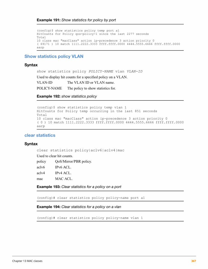
Example 191: Show statistics for policy by port
(config)$ show statistics policy temp port a1HitCounts for Policy qos-policy-1 since the last 2277 secondsTotal10 class mac "macClass" action ip-precedence 3 action priority 0( 69171 ) 10 match 1111.2222.3333 ffff.ffff.0000 4444.5555.6666 ffff.ffff.0000aarp
Show statistics policy VLAN
Syntax
show statistics policy POLICY-NAME vlan VLAN-ID
Used to display hit counts for a specified policy on a VLAN.
VLAN-ID The VLAN ID or VLAN name.
POLICY-NAME The policy to show statistics for.
Example 192: show statistics policy
(config)$ show statistics policy temp vlan 1HitCounts for Policy temp occurring in the last 851 secondsTotal10 class mac "macClass" action ip-precedence 3 action priority 0( 0 ) 10 match 1111.2222.3333 ffff.ffff.0000 4444.5555.6666 ffff.ffff.0000aarp
clear statistics
Syntax
clear statistics policy|aclv6|aclv4|mac
Used to clear hit counts.
policy QoS/Mirror/PBR policy.
aclv6 IPv6 ACL.
aclv4 IPv4 ACL.
mac MAC ACL.
Example 193: Clear statistics for a policy on a port
(config)# clear statistics policy policy-name port a1
Example 194: Clear statistics for a policy on a vlan
(config)# clear statistics policy policy-name vlan 1
Chapter 13 MAC classes 367

Chapter 14
Support and other resources
Accessing Hewlett Packard Enterprise Support• For live assistance, go to the Contact Hewlett Packard Enterprise Worldwide website:
www.hpe.com/assistance
• To access documentation and support services, go to the HP Support Center – Hewlett Packard Enterprisewebsite:
www.hpe.com/support/hpesc
Information to collect
• Technical support registration number (if applicable)
• Product name, model or version, and serial number
• Operating system name and version
• Firmware version
• Error messages
• Product-specific reports and logs
• Add-on products or components
• Third-party products or components
Accessing updates• Some software products provide a mechanism for accessing software updates through the product interface.
Review your product documentation to identify the recommended software update method.
• To download product updates, go to either of the following:
HP Support Center – Hewlett Packard Enterprise Get connected with updates from HP page:
www.hpe.com/support/e-updates
◦
◦ Software Depot website:
www.hpe.com/support/softwaredepot
• To view and update your entitlements, and to link your contracts, Care Packs, and warranties with your profile,go to the HP Support Center – Hewlett Packard Enterprise More Information on Access to HP SupportMaterials page:
www.hpe.com/support/AccessToSupportMaterials
368 HPE ArubaOS-Switch Advanced Traffic Management Guide for WC.16.02

Access to some updatesmight require product entitlementwhen accessed through theHP Support Center– Hewlett Packard Enterprise. You must have a Hewlett Packard Enterprise Passport set up with relevantentitlements.
Websites
LinkWebsite
www.hpe.com/info/enterprise/docsHewlett Packard Enterprise Information Library
www.hpe.com/support/hpescHP Support Center – Hewlett Packard Enterprise
www.hpe.com/assistanceContact Hewlett Packard Enterprise Worldwide
www.hpe.com/support/e-updatesSubscription Service/Support Alerts
www.hpe.com/support/softwaredepotSoftware Depot
www.hpe.com/support/selfrepairCustomer Self Repair
www.hpe.com/info/insightremotesupport/docsInsight Remote Support
www.hpe.com/info/hpux-serviceguard-docsServiceguard Solutions for HP-UX
www.hpe.com/storage/spockSingle Point of Connectivity Knowledge (SPOCK) Storagecompatibility matrix
www.hpe.com/storage/whitepapersStorage white papers and analyst reports
Customer self repairHewlett Packard Enterprise customer self repair (CSR) programs allow you to repair your product. If a CSR partneeds to be replaced, it will be shipped directly to you so that you can install it at your convenience. Some parts donot qualify for CSR. Your Hewlett Packard Enterprise authorized service provider will determine whether a repaircan be accomplished by CSR.
For more information about CSR, contact your local service provider or go to the CSR website:
www.hpe.com/support/selfrepair
Remote supportRemote support is available with supported devices as part of your warranty, Care Pack Service, or contractualsupport agreement. It provides intelligent event diagnosis, and automatic, secure submission of hardware eventnotifications to Hewlett Packard Enterprise, which will initiate a fast and accurate resolution based on your product’sservice level. Hewlett Packard Enterprise strongly recommends that you register your device for remote support.
For more information and device support details, go to the following website:
www.hpe.com/info/insightremotesupport/docs
Chapter 14 Support and other resources 369

Chapter 15
Documentation feedback
Hewlett Packard Enterprise is committed to providing documentation that meets your needs. To help us improvethe documentation, send any errors, suggestions, or comments to Documentation Feedback ([email protected]).When submitting your feedback, include the document title, part number, edition, and publication date located onthe front cover of the document. For online help content, include the product name, product version, help edition,and publication date located on the legal notices page.
370 HPE ArubaOS-Switch Advanced Traffic Management Guide for WC.16.02

Index
Symbols802.1ad QinQ, 300802.1p priority
classifier, 187packet marking, 187
global QoS, 194, 202, 209priority, 187
802.1Q VLAN tagging, 21, 79
Aaccessing
updates, 368alias
with show VLAN commands, 57
Bbandwidth
effect of QoS, 186Bootp
gateway ignored, 62BYOD-redirect
Associate VLAN, 299configuration
distribution switch, 295Configuring
creating a BYOD server, 293configuring, 293
associating a BYOD server, 293client authentication on edge switch, 295creating a BYOD ACL rule, 293
FeaturesVLAN, 290
features, 289interoperability, 292
implementingBYOD-redirect configuration, 294BYOD-redirect configuration example, 294
interoperability, 292Comware, 292
Introduction, 289restrictions, 292show commands, 297show portal free-rule, 298show portal redirect statistics, 298show portal server, 297SNMP interactions, 292VLAN
SNMP, 292
Cclassifier
benefits, 351class configuration, 336
defined, 346, 354editing, 328, 346resequencing, 328viewing, 328, 336, 346
class configuration commands, 323default class configuration, 339default-class configuration, 355defined, 351DSCP codepoint match criteria, 326ICMP match criteria, 329IGMP match criteria, 331IP precedence bits match criteria, 327IPv4 subnet mask match criteria, 352IPv6 match criteria, 325IPv6 prefix match criteria, 352mirroring configuration, 353PBR configuration
marking packets, 337policy configuration, 340
applying to an interface, 341, 349commands, 342, 349creating, 338, 347defined, 337, 347editing, 339–340, 348example, 339, 348marking packets, 337resequencing, 339restrictions, 341viewing, 339, 341, 348
QoS configuration, 339, 353resource usage
viewing, 343restrictions
ICMP rate limiting, 342TCP/UDP match criteria, 331three-step configuration model, 353type of Service DTR bits match criteria, 327VLAN match criteria, 328
classifier-based QoSmarking packets, 187
Command syntaxarp protect vlan, 184class, 323–324, 329, 331, 336, 338–339, 346class resequence ipv4|ipv6|mac , 358class zone, 347clear statistics , 367debug rpvst, 263dhcp-snooping trust, 184disable layer3 vlan, 43gvrp, 79
Index 371

interface, 43, 342interface port-list trkx qinq port-type, 308interface private-vlan promiscuous, 167–170interface qos dscp, 216interface qos priority, 215interface tunnel, 278interface unknown-vlans, 80ip source binding, 185ip-recv-mac-address, 70
interval, 59loop-protect, 134management-vlan, 46max-vlans, 51no class ipv4|ipv6|mac|zone, 357no default-mac-class action mirror , 361no interface qos, 215, 217no policy qos|pbr|mirror|zone, 360no QinQ, 308no qos device-priority, 200–201no qos dscp-map, 219no qos type-of-service, 206no SEQ_NUM class ipv4|ipv6|mac, 360, 362no SEQ_NUM match|ignore, 358no SEQ_NUM remark , 361, 363no service-policy, 364no tcp-push-preserve, 187no vlan, 42no vlan qos, 211, 213policy, 338, 340policy zone, 347portal free-rule, 293portal web-server url, 293primary-vlan, 45QinQ, 306qos device-priority, 199qos device-priority dscp, 201qos dscp-map priority, 218qos protocol, 209qos queue-config, 225qos type-of-service diff-services, 204–205qos type-of-service diff-services dscp, 206qos type-of-service ip-precedence, 202show
policy, 343QinQ, 310vlans, 310–312
show arp-protect, 185show class mac, 364show class ports , 365show class vlan, 365show dhcp-snooping binding, 174Show dhcp-snooping binding private-vlan, 172show egress port-queue drop, 227show gyrp, 76–77show interfaces tunnel, 280
show interfaces tunnel type vxlan statistics, 282show ip source-lockdown bindings, 184show ip source-lockdown status, 184show ip-recv-mac-address, 59, 71show loop-protect, 136show policy , 365show policy ports , 366show policy vlan , 366show portal free-rule, 299show portal tcp-cheat statistics, 298show portal web-server, 298show qos, 193show qos device-priority, 200–201show qos dscp-map, 218show qos port-priority, 215show qos protocol-priority, 210show qos queue config, 225show qos queue-config, 226show qos source-port, 217show qos tcp-udp-port-priority, 195, 197show qos type-of-service, 206show qos vlan-priority, 211, 213show running config, 173show spanning-tree, 127, 245show spanning-tree <port-list>, 127, 247show spanning-tree <port-list> config instance, 131show spanning-tree <port-list> detail , 118show spanning-tree <port-list> instance
detail, 129show spanning-tree bpdu-protection , 116, 239, 249show spanning-tree config , 130, 253, 255show spanning-tree config instance, 131show spanning-tree config vlan, 254show spanning-tree configuration, 236show spanning-tree debug vlan, 260show spanning-tree debug-counters, 144, 259show spanning-tree debug-counters instance , 145–146show spanning-tree detail
, 128show spanning-tree instance, 129
detail, 129show spanning-tree mst-config, 132show spanning-tree pending, 133show spanning-tree root-history, 142show spanning-tree root-history vlan, 257show spanning-tree system-limits rapid-pvst, 250show spanning-tree traps, 258show spanning-tree vlan, 246, 248, 256show statistics policy , 366–367show tcp-push-preserve, 187show tech all, 175show vlan ports, 53show vlans , 52, 54, 80, 172show vlans custom , 56show vlans private-vlan, 170
372 HPE ArubaOS-Switch Advanced Traffic Management Guide for WC.16.02

show vlans private-vlan promiscuous-ports, 171show vxlan, 280spanning-tree, 122
bpdu-filter, 114spanning-tree <port-list> bpdu-protection, 115spanning-tree <port-list> bpdu-protection-timeout,
115spanning-tree <port-list> loop-guard, 137spanning-tree <port-list> pvst-filter, 117spanning-tree <port-list> pvst-protection, 117spanning-tree [ enable | disable ], 235spanning-tree admin-edge-port, 111, 233spanning-tree auto-edge-port, 111, 234spanning-tree bpdu-filter, 234, 236spanning-tree bpdu-protection, 234, 238spanning-tree bpdu-protection-timeout , 117, 231, 238spanning-tree clear-debug-counters, 106, 263spanning-tree config-name, 106spanning-tree config-revision, 107spanning-tree extend system-id, 231spanning-tree force-version, 107spanning-tree forward-delay, 108spanning-tree hello-time, 108, 111spanning-tree ignore-pvid-inconsistency, 231, 239spanning-tree instance, 119
priority, 120vlan, 124
spanning-tree instance path-cost, 120spanning-tree instance priority, 119spanning-tree legacy-mode, 108spanning-tree legacy-path-cost, 108spanning-tree log state-transitions, 231spanning-tree loop-guard, 240spanning-tree max-hops, 109spanning-tree maximum age, 109spanning-tree mcheck, 112spanning-tree mode, 231spanning-tree mode mstp, 106spanning-tree mode rapid-pvst, 230spanning-tree path-cost, 112spanning-tree pathcost, 233spanning-tree pending, 109, 122spanning-tree point-to-point-mac, 112, 234spanning-tree port vlan pathcost, 233spanning-tree port vlan priority path-cost, 233spanning-tree priority, 109, 112, 121spanning-tree root-guard, 113, 234spanning-tree show <port> configuration , 114spanning-tree tcn-guard, 113, 235spanning-tree trap, 110, 258spanning-tree trap errant-bpdu , 115, 238spanning-tree vlan, 230spanning-tree vlan [ enable | disable ], 235spanning-tree vlan forward-delay, 232spanning-tree vlan hello-time, 232
spanning-tree vlan maximum age, 232spanning-tree vlan priority, 232spanning-tree vlan root, 233static-vlan, 41svlan, 306tcp-push-preserve, 187tunnel destination, 279tunnel mode, 278tunnel source, 278virtual-network VN-ID, 279vlan, 39–40, 342vlan portal web-server, 293, 299vlan private-vlan isolated | community , 167–169vlan private-vlan primary, 167–169vlan private-vlan primary | isolated | community , 169vlan qos dscp, 213vlan qos priority , 60, 211vxlan disable, 277vxlan enable, 277vxlan tunnel tunnel-id, 279vxlan udp, 278zone service policy, 349
configurationfactory default, 33, 38
contacting Hewlett Packard Enterprise, 368creating S-VLANs
in QinQ , 306customer self repair, 369
Ddefault settings
ip-recv-mac-address interval, 59management VLAN, 46MSTP, 105QinQ, 313restoring MAC address , 70VLAN name, 39, 52VLAN qos priority, 60
default VLAN, 38delete
Multiple VLANs, 42DHCP
gateway ignored, 62documentation
providing feedback on, 370DSCP codepoint
packet markingglobal QoS, 196
Ggateway
manual config priority, 62GVRP
ACL restrictions, 82advertisement, 82, 85
Index 373

advertisement responses, 83benefits, 81converting dynamic to static, 83converting to static VLAN, 82dynamic VLAN and reboots, 82dynamic VLANs always tagged, 75in QinQ, 307IP addressing, 83learn, 80maximum VLANs, , 82non-GVRP aware device, 82operating notes, 82port control options, 86port-leave from dynamic, 86recommended tagging, 86tagged, dynamic VLAN, 75unknown VLAN, 86unknown VLAN options, 84VLAN behavior, 33VLAN, dynamic adds, 37
GVRP blockdisabling, 80
IIANA, protocol numbers, 329IP
gateway, 62traffic priority based on ToS field, 202types of service
configuring priority, 202IP address
match criteria, 325global QoS, 199
IP precedence bitsmatch criteria, 327
IPv4ARP VLAN requirement, 66mask used in match criteria, 333, 352protocol VLAN ARP requirement, 39
IPv6classifier, 323management VLAN , 63match criteria
overview, 355prefix mask, 326, 352
traffic class compared to IPv4 ToS fieldtype of Service,
Jjumbo frames
GVRP, 79
LLayer-3 protocol
match criteria
global QoS, 209loop protection
MSTPtrap transmit interval, 135
used for unmanaged devices, 151
MMAC address
duplicate, 30per switch, 30per VLAN, 30same for all VLANs, 67single forwarding database, 30
MAC classescreating policy, 360overview, 357switch restrictions, 357
marking packetsclassifier-based QoS, 187
match criteriaclassifier-based, 354DSCP codepoint, 326ICMP, 329IGMP, 331IP address, 325IP-device, 199Layer-3 protocol, 209TCP/UDP, 194ToS bits, 327
meshmanagement VLAN, 63QinQ, 317
messageVLAN already exists, 41
mirroringclassifier-based configuration, 353
MSTP see spanning tree (MSTP)Multiple Instance Spanning Tree see spanning tree (MSTP)Multiple port-based VLANs, 20
Ooutbound port queue (QoS)
configuring the number of queues, 226determined by 802.1p priority, 186determined by DSCP policy, 186
Ppacket marking
802.1p priority, 187classifier-based QoS, 187
portconfiguring types in QinQ, 308monitoring, 67
port egress-queue drop counters, 227port trunk
374 HPE ArubaOS-Switch Advanced Traffic Management Guide for WC.16.02

VLAN, 67port-types
QinQ, 308priority
configuring number of queues, 225priority (QoS)
changing queues per port, 225criteria for prioritizing packets, 190
Private VLANscommunity port, 164community VLANs, 163dynamic ARP protection, 184dynamic IP lockdown, 184error messages, 182Feature to category mapping table, 166interaction with multicast protocols(IGMP/MLD), 185interaction with other features, 166interactions, 183interactions with bridging protocols, 183interactions with virtual ports, 183interswitch link (ISL) port, 164IP address assignment, 165isolated access port, 164isolated VLANs, 163member port, 164MTM test mode/debug, 185multicast hardware filter, 185overview, 163port types, 164Ports and layer 2 connectivity table, 165primary VLANs, 163promiscuous port, 164PVLAN configuration categories table, 166PVLANs across multiple switches, 164restrictions, 183security interactions, 184types, 163validation rules, 175validations, errors, and restrictions, 175
protocolARP requirement, 66limit, 34
PVLANsoverview, 163
PVSTenabling, disabling , 117manually re-enabling port , 117show configured ports, 118
QQinQ
assigning ports to VLANs, 315c-tagged interfaces not supported, 317changing bridge modes, 316, 318configuring, 301, 306, 308
configuring port types, 315configuring ports, 309configuring VLANs, 301deleting S-VLANs, 306disabling, 308disabling GVRP at interface, 307duplicate VIDs, 314enabling, 306, 313erasing configurations when changing modes, 318features and benefits, 301GVRP, 309impacts on LACP, 309impacts on mirroring/monitoring, 309impacts on other features , 317–318interoperating with non-HPE devices, 317IP support, 316management VLAN, 317meshing, 317mixed VLAN mode, 313, 316port moving from C-VLANs to S-VLANs, 309port S-VLAN membership, 306primary VLAN, 317provider edge bridge, 316provider edge bridge and core bridge, 302purpose, 300restrictions, 316S-VLAN mode, 313S-VLANs and C-VIDs, 303service provider, 300show commands, 309tpid value, 317updating VLAN types, 317uplink ports, 304use model, 300VID configuration options, 317voice VLANs not supported, 317
Quality of Serviceconfiguring the number of outbound queues, 226criteria for prioritizing outbound packets, 190feature description, 186inbound traffic on network edge, 187match criteria, 194number of priority queues, 225outbound VLAN traffic, 187packet classification, 190packet marking, 187
classifier-based QoS, 187priority settings mapped to downstream devices, 191queue configuration, 225
RRapid per-VLAN spanning tree, 230
see also RPVST+remote support, 369resequencing
Index 375

class configuration, 336policy configuration classifier, 340
routingnon-routable VLAN, 63
RPVST+, 230see also Rapid per-VLAN spanning treeBPDU filtering, 236BPDU protection
configuring and managing, 237BPDU status, 249configuration steps, 230debug, 263debug counters , 259debug counters per-port per-VLAN, 260debug counters per-VLAN, 260debug output, 261default configuration, 267enabling or disabling, 235event log messages, 262forward delay, 232global configuration per port
displaying, 255global configuration per port per VLAN
displaying, 256global settings, 231maximum age, 232mode selection, 231operating notes, 267per-port per-VLAN settings, 233per-port settings, 233per-VLAN settings, 232priority, 232restrictions, 268root bridge, 233sample network,status for a specific port list, 247status for a VLAN, 246traps
enabling and displaying, 258VLAN and vPort limits, 250
Sshow vlans private-vlan, 170spanning tree
comparing options, 264MSTP
active path, 155BPDU, 105, 109, 112, 155broadcast storm, 151change VLAN instance, 106CIST, 109CIST root, 111compatibility mode, 107compatibility with RSTP or STP, 159configuration steps, 104
CST, 156CST status, 128debug counters, 144–146default settings, 105display statistics and configuration, 126enabling a region, 122enabling, disabling, 121fault tolerance, 154forward delay, 108forwarding state, 111general operation, 151hop count, 109in a switch mesh, 154instance, 106, 118instance mapping, 124instance status, 129instance types, 157instance VLAN, 123IST instance, 119, 124IST port priority, 121loop protection, 161MIB support, 126MSTI port priority, 120operating rules, 158operation, 153pending configuration, 133pending option, 107per-port parameters, 111planning for, 104port states, 155preconfigure VLANs in instance, 124priority, 105priority resolution, 120priority, device, 110PVST filtering , 161PVST protection , 160redundant links, 156region, 151region configuration, 132region name, 106regions, 154root history, 142root switch instance, 119routed traffic, 155saving current configuration, 126troubleshooting, 141trunked link, 130, 157viewing global configuration, 130VLAN instance assigned, 119VLAN membership, 157VLAN range option, 125with legacy STP and RSTP, 156with VLANs, 156
RPVST+admin-edge-port, 233
376 HPE ArubaOS-Switch Advanced Traffic Management Guide for WC.16.02

auto-edge-port, 234BPDU filtering, 234BPDU protection, 234global configuration, 253global configuration per VLAN, 254global status, 245history of root bridges, 257ignore PVID inconsistency, 239loop guard, 240root guard, 234status for a port list and VLAN, 248TCN guard, 235troubleshooting, 257
SNMPtraps, 110
VLAN effect on, 67subnet address, 17support
Hewlett Packard Enterprise, 368SVLAN
delete multiple, 42
TTCP/UDP
match criteria, 194TCP/UDP, 331
operators, 332–333packet classification
global QoS, 194well-known port names, 332
ToS, 187, 202see also Type-of-Servicecompared to IPv6 traffic class byte,
Type of ServiceDTR bits as match criteria, 327
Type-of-Service, 187, 202see also ToSQoS, 202using to prioritize IP traffic, 202
Type-of-Service field (IP)configuring packet priority, 202
Uuntagged
VLAN, 34updates
accessing, 368
VVID, 210
see also VLAN-IDlimit, 33
VLANalready exists message, 41broadcast domain, 19
classifier match criteriaVLAN ID, 328
configuration, 38convert dynamic to static, 41customizing output, 56dedicated management, 61default, 19default VLAN, 61default VLAN name change, 61default VLAN VID, 61delete multiple, 42deleting, 39, 42, 66deleting with member ports, 39double-tagging QinQ frame size increases, 316duplicate MAC address, 30dynamic, 16, 19, 38, 41effect on spanning tree, 67environments, 18external protocol router, 68gateway IP, 62GVRP, auto, 34heartbeat packets, 69IP interface relationship, 67layer-3 broadcast domain, 19limit, 33, 38MAC address verification, 59, 71maximum capacity, 37missing VLAN, 37multiple forwarding database, 30multiple VLANs on port, 28non-routable, 63number allowed, including dynamic, 37obtaining IP address, 47
when host is on a different VLAN than the DHCP server,50
port configuration, 30port monitoring, 67port trunk, 67primary, 35, 45, 61primary VLAN not allowed, 45primary with DHCP, 66prioritizing traffic with QoS, 210protocol, 21, 28, 39, 53–54, 66–67
capacity per VLAN, 66example, 29forbid, 41IPv4 routing, 18non-routable, 18, 23primary VLAN not allowed, 62router, external, 19routing, 19tagged member, 18tagging, 18traffic separation, 16untagged packet forwarding, 23
Index 377

protocol compared to port-based, 18protocol routing, 68restrictions, 68routing between VLANs, 19routing options, 21show VLAN ports detail, 53single forwarding database, 30static, 16–17, 38, 61status, 52subnet, 19tagged, 34tagging, 28
rules, 23untagged, 38untagged operation, 24untagged,, 34VID, 27–28voice, 20, 52–53, 55, 66voice configuration, 39
VLAN-ID, 210see also VID
VLANsdesignated, 19port-based, 19protocol-based, 19
Voice VLANs, 59VoIP
operating rules, 66VPN solution for MANs
QinQ, 301VXLAN
configuration procedures, 277feature interaction table, 271forwarding, 269fully meshed network, 269hub spoke network, 270OpenFLow interaction, 275overview, 269procedures for configuration, 277restrictions, 271validation rules, 283
Wwebsites, 369
customer self repair, 369write memory
converting dynamic to static VLAN, 82
378 HPE ArubaOS-Switch Advanced Traffic Management Guide for WC.16.02


