IEA HPC Annex 50: Task 1 Country Report Austria Page 1 HPT Annex 50 Heat Pumps in Multi-Family Buildings Task 3.1: Optimized refrigeration cycle configuration for Air-Water Heat Pumps for renovated, unrenovated and new MFH Country Report AUSTRIA Edited by (A. Zottl, M. Lauermann, S. Zibuschka) April 2020, Version 2.0
Transcript
IEA HPC Annex 50: Task 1 Country Report Austria Page 1
HPT Annex 50
Heat Pumps in Multi-Family
Buildings
Task 3.1: Optimized refrigeration cycle
configuration for Air-Water Heat Pumps for
renovated, unrenovated and new MFH
Country Report
AUSTRIA
Edited by (A. Zottl, M. Lauermann, S. Zibuschka)
April 2020, Version 2.0
IEA HPC Annex 50: Task 1 Country Report Austria Page 2
IEA HPC Annex 50: Task 1 Country Report Austria Page 4
3. Methodology The following steps were taken to select the optimum refrigeration cycle configuration for Air-Water
Heat Pumps for the different application:
• Selection of suitable refrigerants and definition of typical applications based on preliminary
work and literature research
• Definition of the refrigeration circuit variants to be investigated
• Design of the Air-Water Heat Pump model in the simulation environment Dymola/Modelica
• Validation of the model with experimental data from preliminary work
• Simulation of the defined variants
• Calculation of the SCOP for selecting the most suitable refrigeration circuit configuration for
each application
• Generation of the characteristic curves by means of regression analysis per use case for
implementation in TRNSYS
4. Definition of use cases Based on the elaborated building stock characteristics in the HPT Annex 50 Task 1 report (IEA HPT
Annex 50 Task 1, 2017) and investigations in the GreenHP project (GreenHP, 2016), three use cases
were defined (Table 1). From the preliminary work, a typical Austrian MFH with 8 to 10 housing units
and with living spaces per housing unit of approx. 70 to 100 m² could be described. In addition, in
connection with the standard EN 14825 (EN 14825, 2018), the design temperatures for the heating
system of the different use cases were defined. Table 1 shows the heating load, the specific heating
load, the specific heating demand and the design temperature of the heating system for the three
applications.
Table 1: Definition of MFH use cases
use cases - MFH heat load specific heat
load
specific heating demand
system supply
temperature
- kW W/m² kWh/m² °C
new 20 30 45 35
refurbished 30 50 65 55
unrefurbished 50 80 120 65
In the course of the GreenHP project (GreenHP, 2016), the heating capacity for a refurbished MFH was
set at 30 kW and the system temperatures for the design at 55 °C. The subsequent experimental
investigations served to validate the Air to Water heat pump model for the simulations in this IEA HPT
Annex 50.
IEA HPC Annex 50: Task 1 Country Report Austria Page 5
5. Selection of refrigerants and definition of refrigeration cycles On the basis of literature research and from preliminary work (GreenHP, 2016 and Store4Grid, 2015)
the refrigerants and definition of refrigeration cycles were selected.
The refrigerants selected for the numerical comparison are R290, R410A, R134a and R1234zee. The
idea was to use state of the art refrigerants (R410A and R134a) as a benchmark and to have a closer
look on using refrigerants with low global warming potential (GWP). In Figure 1 the GWP of the
selected refrigerants are shown.
Figure 1: GWP of the selected refrigerants (Bitzer, 2018)
Therefore, R290 has been selected based on the investigations in the EU-funded project GreenHP and
R1234zee (Honeywell, 2019) as an alternative to replace R134a for applications with high supply
temperatures. Within the project GreenHP (GreenHP, 2016) only refrigerants with low GWP were
considered. To determine the best suited refrigerant from environmental and technical aspects, a life
cycle climate performance (LCCP) analysis was performed. For the analysis, four refrigerant options
were selected: two hydrocarbons (R290, R1270) and two low GWP hydrofluorocarbons (R152a,
R1234yf). During the anaylsis in IEA HPT Annex 50 the slightly different R1234zee was used instead
R1234yf as R1234zee has close thermodynamic properties to R134a (Honeywell, 2019 and Bitzer,
2018). The LCCP of the GreenHP project showed that indirect emissions dominate the total lifetime
emissions, indirect emissions accounted for over 99%. Therefore, choosing the most environmentally
friendly refrigerant was also a choice of the most efficient refrigerant. Of the low GWP refrigerants,
R1234yf had the highest lifetime emissions, while R152a, R290 and R1270 emitted almost the same
CO2 equivalents over their lifetime, with hydrocarbons showing the best environmental performance.
Taking into account the possible limitations in the use of HFC refrigerants as well as other aspects of
refrigerant use, preference was given to hydrocarbons, of which the refrigerant R290 (propane) was
selected as the refrigerant on which the heat pump design is based (GreenHP, 2016).
Additional to the selection of the refrigerants, three different refrigerant cycle configurations were
defined for the comparisons, see Figure 2:
• Single stage
• iHX (internal heat exchanger)
• EVI (enhanced vapour injection)
IEA HPC Annex 50: Task 1 Country Report Austria Page 6
Figure 2: Refrigerant circuit configurations, from left to right: single stage, suction gas HEX, EVI
The single stage refrigeration cycle, Figure 2 (left) consists of the main components: evaporator,
condenser, compressor and expansion valve. This refrigeration cycle configuration represents the
simplest variant in terms of refrigeration cycle design and control.
A suction gas superheater, Figure 2 (middle) is usually used when some superheating of the refrigerant
is required before compression e.g. R290 needs higher superheating for a safe compressor operation.
After the refrigerant has condensed on the high-pressure side, the liquid is cooled down by the suction
gas heat exchanger to heat the suction gas before entering the compressor. For small capacities a tube-
in-tube heat exchanger is usually installed for this purpose.
In the refrigeration cycle configuration EVI (Figure 2 right), compared to the single stage configuration,
a compressor with injection port, a second expansion valve (injection valve) and an economizer are
provided. The compressor design is divided into two compressor stages by the injection of refrigerant.
The pressure level of the injection is fixed by the position of the injection port on the compressor.
When controlling the injection valve upstream of the economizer, care must be taken to ensure that
the compression cycle remains within prescribed limits. The main focus is on sufficient hot gas
overheating at the compressor outlet (avoidance of compression into the wet steam area, oil
separation in the hot gas) and to improve the efficiency at operating conditions where high
temperature lifts between heat source and heat sink occur e.g. Air-Water Heat Pump operation at low
out door temperatures. The main benefit of the EVI configuration in terms of efficiency is due to the
fact, that not all the refrigerant is expanded to the evaporator pressure. A certain fraction is expanded
to intermediate pressure level, then evaporated in the economizer and injected back to into the
compressor. As a result, the compressor work is slightly reduced depending on the present pressure
ratio. The higher it is, the higher is the benefit by the EVI configuration. A second benefit arises from
the fact that the during injection on intermediate pressure level, the discharge temperature decreases.
Depending on the refrigerant, a significant extension of the compressor operating envelope can be
achieved.
Einfach Sauggasüberhitzer EVI
IEA HPC Annex 50: Task 1 Country Report Austria Page 7
6. Dymola Simulation The refrigeration cycle simulations were done in the simulation environment Dymola/Modelica3 based
on the input parameters described in chapter 4 and 5.
6.1. Variants
Based on the determined use cases for different multi-family house categories (new, unrenovated
existing, renovated existing), the specified refrigerant cycle variants and the selected refrigerants the
simulation variants have been defined (Table 2). In total 24 different variants have been specified for
the numerical comparisons.
Table 2: Overview of the investigated variants
For the new building category, a total of six
different variants were compared:
1. Single stage refrigerant cycle R290
2. With suction gas heat exchanger R290
3. EVI (Enhanced Vapour Injection) R290
4. Single stage refrigerant cycle R410A
5. With suction gas heat exchanger R410A
6. EVI (Enhanced Vapour Injection) R410A
Nine different variants have been identified for each
of the categories refurbished and unrefurbished
building:
1. Single stage refrigerant cycle R290
2. With suction gas heat exchanger R290
3. EVI (Enhanced Vapour Injection) R290
4. Single stage refrigerant cycle R134a
5. With suction gas heat exchanger R134a
6. EVI (Enhanced Vapour Injection) R134a
7. Single stage refrigerant cycle R1234zee
8. With suction gas heat exchanger R1234zee
9. EVI (Enhanced Vapour Injection) R1234zee
6.2. Modelling
In order to compare and evaluate different refrigeration circuit configurations, numerical models were
created within the afore mentioned simulation environment Dymola/Modelica. For the thermal
modelling of the heat pump components the TIL library4 was used, which is widely used in refrigeration
engineering. The modelling of the compressor - the core component in heat pumps - was performed
using measured data and an efficiency-based approach. The compressor is described by the isentropic
and volumetric efficiency, which change depending on the pressure ratio and the condensing or
evaporating temperature, as well as the compressor speed. The isentropic efficiency is based on the
ideal isentropic compression and also takes into account suction and discharge pressure losses,
internal leakage, re-expansion of the compressed refrigerant and mechanical friction. The volumetric
efficiency describes the ratio between the geometrically possible mass flow and the actual mass flow
through the compressor.
The numerical model is shown in Figure 3. The generic structure makes it possible to cover both the
single stage refrigeration circuit and the more complex variants with EVI by simply activating or
deactivating individual components (such as suction gas superheater, EVI injection, economizer) with
IEA HPC Annex 50: Task 1 Country Report Austria Page 8
Figure 3: Numerical model in /Dymola/Modelica®
6.3. Model validation
In the first step, the completed model was calibrated with the measurement data of the GreenHP-
prototype unit (Figure 4).
Figure 4: Green HP prototype (GreenHP, 2016)
Numerisches Modell in Modelica/Dymola
IEA HPC Annex 50: Task 1 Country Report Austria Page 9
The refrigeration cycle configuration of the GreenHP-prototype unit is equipped with EVI as shown in
Figure 2. The refrigerant used is R290 (propane) and the unit is operated with a scroll compressor. The
calibration is mainly aimed at the compressor characteristics, which have a significant influence on the
overall efficiency and performance of the refrigeration circuit. Table 3 shows the results of GreenHP-
measurements based on EN 14825 (EN 14825, 2018), which means part load tests at different outdoor
temperatures and supply temperatures. From the entire measurement campaign, seven test points
were used for the model calibration.
Table 3: Results of the GreenHP-measurements based on EN14825
The isentropic and volumetric efficiency of the compressor were approximated with 2nd degree
polynomials depending on pressure ratio and speed. Figure 5 shows a comparison of the measured
data and the simulation. In this diagram, the measured values are plotted on the x-axis and the
simulated comparison values on the y-axis. If the points are congruent on a 45 °C straight line, then
one speaks of a good model quality over the entire operating range.
The heating power and the electrical power consumption show a good agreement. The largest
deviation is about 5 %. The coefficient of performance (COP) of the heat pump, which relates the
heating output and the electrical power consumption, shows a difference of around 15% at the
operating point A12/W32, i.e. at high source inlet temperatures and low user outlet temperatures.
Except for this one operating point, however, the difference is of the same order of magnitude as for
the heating power and the electrical power consumption.
The larger deviation for A12/W32 is an indication that not all influencing variables have been captured
in the compressor modelling. As described above, the pressure ratio and the speed were taken into
account. These two variables are sufficient for the majority of the operating points. For a more
accurate model, more influencing variables, such as evaporating temperature, superheat, etc. would
have to be included in the numerical compressor characteristics.
avera
ge
heating
capacity
avera
ge
pow
er
inp
ut
Com
pre
ssor
speed
Fan s
pee
d
EV
I valv
e
opera
tio
n
CO
P
[kW] [kW] [%] [%] [-] [-]
A-7/W52 25.07 11.42 92 82 auto 2.19
A2/W42 15.71 4.51 44 70 auto 3.48
A7/W36 10.66 2.61 27 64 auto 4.09
A12/W32 11.15 2.32 25 60 auto 4.80
A7/W55 19.96 6.67 50 64 auto 2.99
A7/W55 1
19.54 6.51 48 62 auto 3.00
A-10/W55 2
29.00 14.36 - - - 2.02
1 measured with higher air humidity at the beginning of the icing of the evaporator
2 calculated based on compressor data
IEA HPC Annex 50: Task 1 Country Report Austria Page 10
Figure 5: Validation of the numerical model with the GreenHP-measurement data
As a result of the model calibration, so-called compressor maps are available which describe the
volumetric and isentropic efficiency as a function of pressure ratio and speed. Figure 6 and Figure 7
show the mentioned compressor maps. On the left, an e axisymmetric view is shown of the polynomial
surface for the volumetric efficiency and the isentropic efficiency. On the right, the same information
is shown as contour plot with distinctive isolines. The blue dots refer to the “GreenHP” measurement
data.
Figure 6: Calibrated volumetric efficiency with GreenHP-measurement data (blue)
Heizleistung Elektrische Leistungsaufnahme COP
IEA HPC Annex 50: Task 1 Country Report Austria Page 11
Figure 7: Calibrated isentropic efficiency with the GreenHP-measurement data (blue)
For both maps it is true that the GreenHP-measurement data - which are also the support points for
the 2nd degree polynomial - show a distinct distribution with respect to the speed but give little
information about the influence of the pressure ratio. Along the GreenHP operating points the
modelled compressor characteristics can represent the measured data very well, but beyond that -
and especially with deviating pressure ratios, less information is available from the measurements. In
order to compensate, we took information from literature on how the compressor characteristics
change with varying pressure ratios. In (Granryd et al. 2005) a correlation for the pressure difference
and the isentropic and volumetric efficiency is given, see Figure 8 in the middle (literature). With this
information it was possible to create a compressor map as seen in Figure 8 (right), that better reflects
the influence of the different refrigerants than the current underlying map, see Figure 8 (left). The
polynomial surface is now fitted with the constructed support points over the entire range (the red
ones) rather than from the limited GreenHP measurement data (the blue ones).
Figure 8: Generation of an improved compressor maps: GreenHP-measurement data combined with literature.
IEA HPC Annex 50: Task 1 Country Report Austria Page 12
Figure 9 shows the improved compressor maps. While the volumetric efficiency has a rather low
dependency on the pressure ratio, the isentropic efficiency shows significant decrease at higher
pressure ratio values. The following results are based on the updated map in order to get a better
understanding of the influence of the different refrigerants and temperature levels.
Figure 9: Improved compressor maps. Isentropic efficiency (left) and volumetric efficiency (right). The original GreenHP-measurement data are indicated as blue dots
6.4. Simulation results
The 24 defined variants were simulated in 29 defined operating points in accordance with EN 14825
using the model that was created and validated. Table 4 shows operating points as a function of
temperature and compressor speed. For each operating point, the heat output, the electrical power
consumption of the fan, the coefficient of performance (COP), the electrical power of the heat pump
and the ratio of the compressor displacement compared to the design variant were calculated (area
marked red in the table).
Table 4: Calculated operating points
Case T source in T sink out Compressor speed FanPower Heating
capacity
Pel COPh Size
- °C °C % W kW kW - -
0 -10 55 25.0
1 -10 55 35.0
2 -10 55 54.0
3 -10 55 88.0
4 -10 55 100.0
5 -7 52 25.0
6 -7 52 35.0
7 -7 52 54.0
8 -7 52 88.0
9 -7 52 100.0
10 2 42 25.0
11 2 42 35.0
12 2 42 54.0
13 2 42 88.0
14 2 42 100.0
15 7 36 25.0
16 7 36 35.0
17 7 36 54.0
18 7 36 88.0
19 7 36 100.0
20 12 32 25.0
21 12 32 35.0
22 12 32 54.0
23 12 32 88.0
24 12 32 100.0
28 -7 52 89.3
27 2 42 42.0
26 7 36 25.0
25 12 32 25.0
29 -10 55 99.9
29 -10 55 99.9
IEA HPC Annex 50: Task 1 Country Report Austria Page 13
Based on the operating points explained in Table 4 an operating map for each heat pump variant was
generated. In Figure 10 the operating map for the refrigeration cycle “EVI with R290” is shown as an
example for the variant existing refurbished MFH. The green line represents the heating curve
according EN14825 and the red dots show the operating points which are needed for the later SCOP
calculations.
Figure 10: Operating map example for the variant refurbished MFH with EVI and R290
Figure 11, Figure 12 and Figure 13 show the results of the numerical comparison for the new building,
the refurbished existing building and the unrefurbished existing building. The bars represent the partial
load points as defined in EN14825. The points show the results of compressor speed variations in the
range between 25 % and 100 %. Each refrigerant belongs to a certain colour palette. Green for R290,
red for R410A, orange for R134a and blue for R1234zee. The first configuration is the EVI variant
followed by single stage and suction gas heat exchanger iHX.
The comparison for all building categories shows that the EVI configuration is the best option in terms
of COP for all selected refrigerants, except for R290 at 12 °C outside air temperature within the building
category new and for R1234zee within the building categories refurbished and unrefurbished. In these
cases, the EVI injection has been deactivated in the model because of the low pressure ratio.
The difference between the single stage variant and the variant with suction gas heat exchanger is
hardly or not at all noticeable, depending on the refrigerant. This is mainly due to the alignment of the
isentropes and the saturated vapour curve in the log pH diagram.
IEA HPC Annex 50: Task 1 Country Report Austria Page 14
Figure 11: Results for the new building
Figure 12: Results for refurbished existing buildings
IEA HPC Annex 50: Task 1 Country Report Austria Page 15
Figure 13: Results for unrefurbished buildings
For the building category “new”, the EVI variant with R290 as refrigerant has the highest COPs. This is
most evident for the outside air temperatures of 2 °C and 7 °C. At an outside air temperature of 12 °C
the EVI variant with R410A is the most efficient.
For “refurbished” and “unrefurbished” existing buildings, the EVI variants also have the highest COPs
- regardless of the refrigerant. At an outside air temperature of 12 °C, the values for the unrefurbished
and the refurbished existing building are in the same range, slightly higher for the unrefurbished
category. Following the EN14825 operating points, the delivery temperature at 12 °C outside air
temperature are almost identical for both building categories. The higher delta T at the supply side for
the unrefurbished category results in a more favourable operating point in the unrefurbished stock
than in the refurbished one.
Figure 14: Pressure ratio depending on refrigerant and use case
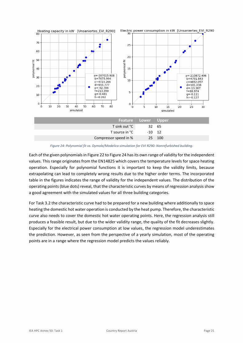
IEA HPC Annex 50: Task 1 Country Report Austria Page 16
As described in Figure 9 the isentropic efficiency is dependent on the pressure ratio, therefore the
pressure ratio also influences the efficiency. In Figure 14 the pressure ratios depending on the
refrigerant and use cases is shown. It can be seen that for the higher temperature applications, R290
has the most favourable pressure ratios, for the new MFH application R410A is slightly better than
R290 (Figure 18).
In addition to the performance of the different variants the compressor displacement was analysed.
Depending on the use case and the refrigerant, different compressor displacements were needed to
reach the design heating capacities. The compressor displacement is also an indicator for the
refrigerant mass needed to operate the unit and how compact the components of the unit can be
designed.
Figure 15: Compressor displacement reduction for new MFH variants
Figure 16: Compressor displacement reduction for refurbished MFH variants
IEA HPC Annex 50: Task 1 Country Report Austria Page 17
Figure 17: Compressor displacement reduction for unrefurbished MFH variants
In Figure 15, Figure 16 and Figure 17 the compressor displacement size reduction is shown. The basis
for the reduction potential is always the worst case (highest displacement) per use case. For the high
temperature applications R290 with EVI offers a reduction potential of more than 50 % compared to
R1234zee with the single stage cycle. For all refrigerants it can be seen that only the use of EVI can
reduce the compressor displacement by more than 10 % in comparison with the single stage cycle.
Only for the new MFH use case R410A has a higher size reduction potential than R290.
7. SCOP Calculation In addition to the criteria discussed in the previous chapters, such as GWP and refrigerant charge
quantity, the most efficient of the 24 variants was calculated for the three use cases new, refurbished
and unrefurbished MFH based on SCOP calculations. The SCOP represents the seasonal efficiency
according EN14825 and can be defined as calculated seasonal performance factor. In contrast to the
COP, not only the efficiency of a single operating point is considered here, but the entire operating