Illustrations and Parts Lists .................................... 16–19
KEEP THIS MANUAL
DescriptionThe HRD-1 and HRD-58 Fairmont Ground Rod Drivers are heavy-duty, hydraulically powered reciprocating tools designed for driving ground rods of various lengths. The high power-to-weight ratio and low vibration reduce operator fatigue and increase productivity. Included is a remote double-acting operating valve that allows operation on either open-center or closed-center hydraulic systems.
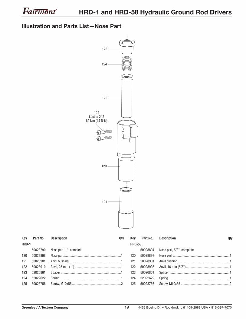
The HRD-1 can drive rods up to 25 mm (1") in diameter. The HRD-58 accommodates rods up to 16 mm (0.625") in diameter.
SafetySafety is essential in the use and maintenance of Fairmont tools and equipment. This manual and any markings on the tool provide information for avoiding hazards and unsafe practices related to the use of this tool. Observe all of the safety information provided.
Purpose of this ManualThis manual is intended to familiarize personnel with the safe operation and maintenance procedures for the following Fairmont tools:
• HRD-1 1" Ground Rod Driver
• HRD-58 5/8" Ground Rod Driver
Keep this manual available to all personnel.
Replacement manuals are available upon request at no charge.
Other Publications
Tool Owners/Users
SAE Standard J1273 (Hose and Hose Assemblies): Publication 99930323
All specifications are nominal and may change as design improve-ments occur. Greenlee Textron Inc. shall not be liable for damages resulting from misapplication or misuse of its products.
Loctite and 242 are registered trademarks of Loctite Corporation.
HRD-1 and HRD-58 Hydraulic Ground Rod Drivers
Greenlee / A Textron Company 3 4455 Boeing Dr. • Rockford, IL 61109-2988 USA • 815-397-7070
IMPORTANT SAFETY INFORMATION
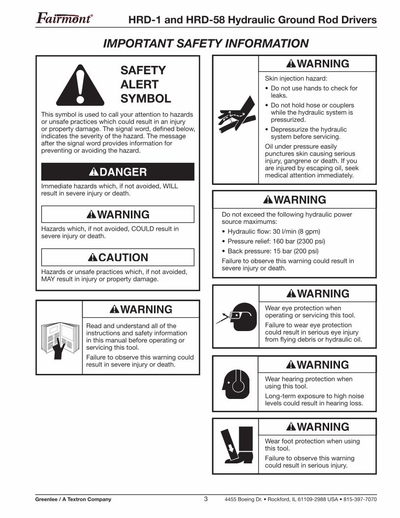
Wear foot protection when using this tool.
Failure to observe this warning could result in serious injury.
Wear hearing protection when using this tool.
Long-term exposure to high noise levels could result in hearing loss.
Wear eye protection when operating or servicing this tool.
Failure to wear eye protection could result in serious eye injury from flying debris or hydraulic oil.
Do not exceed the following hydraulic power source maximums:
• Hydraulic flow: 30 l/min (8 gpm)
• Pressure relief: 160 bar (2300 psi)
• Back pressure: 15 bar (200 psi)
Failure to observe this warning could result in severe injury or death.
Skin injection hazard:
• Do not use hands to check for leaks.
• Do not hold hose or couplers while the hydraulic system is pressurized.
• Depressurize the hydraulic system before servicing.
Oil under pressure easily punctures skin causing serious injury, gangrene or death. If you are injured by escaping oil, seek medical attention immediately.
This symbol is used to call your attention to hazards or unsafe practices which could result in an injury or property damage. The signal word, defined below, indicates the severity of the hazard. The message after the signal word provides information for preventing or avoiding the hazard.
Hazards or unsafe practices which, if not avoided, MAY result in injury or property damage.
Hazards which, if not avoided, COULD result in severe injury or death.
Immediate hazards which, if not avoided, WILL result in severe injury or death.
SAFETY ALERT SYMBOL
Read and understand all of the instructions and safety information in this manual before operating or servicing this tool.
Failure to observe this warning could result in severe injury or death.
HRD-1 and HRD-58 Hydraulic Ground Rod Drivers
Greenlee / A Textron Company 4 4455 Boeing Dr. • Rockford, IL 61109-2988 USA • 815-397-7070
IMPORTANT SAFETY INFORMATION
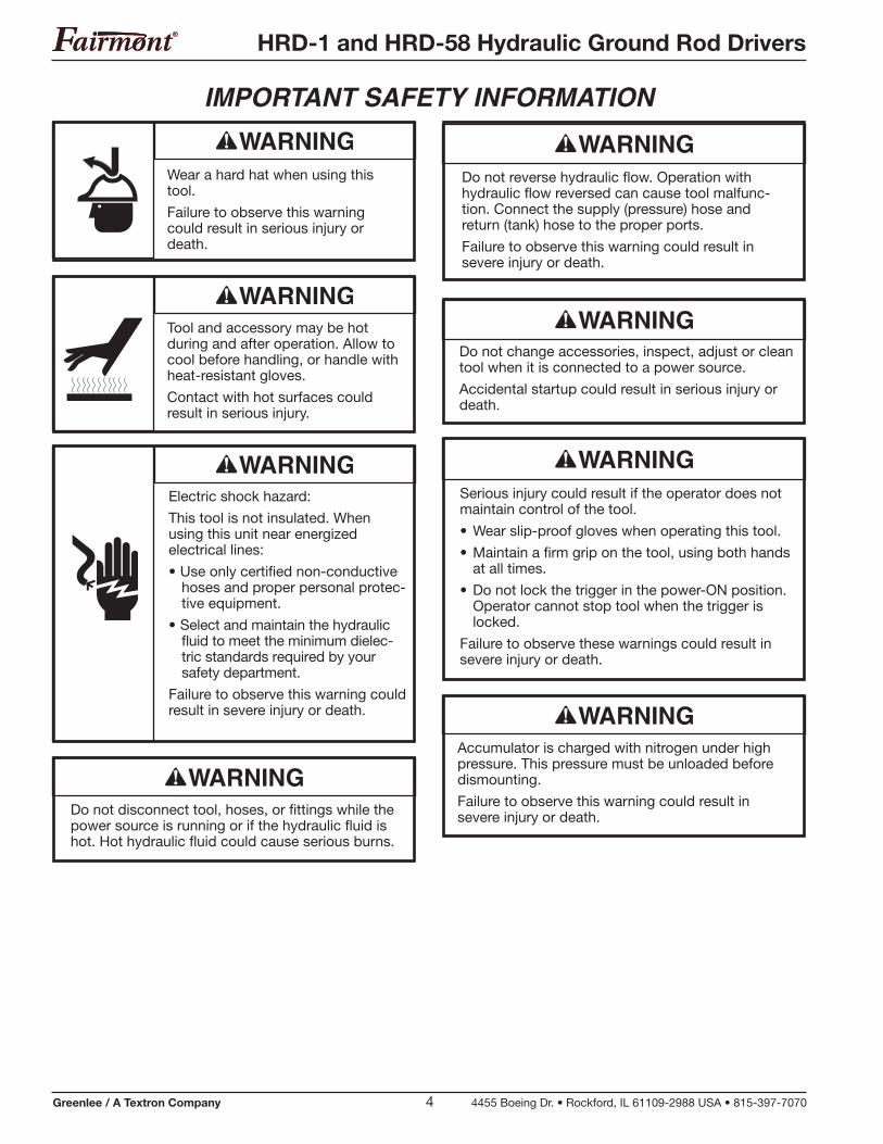
Wear a hard hat when using this tool.
Failure to observe this warning could result in serious injury or death.
Tool and accessory may be hot during and after operation. Allow to cool before handling, or handle with heat-resistant gloves.
Contact with hot surfaces could result in serious injury.
Electric shock hazard:
This tool is not insulated. When using this unit near energized electrical lines:
• Use only certified non-conductive hoses and proper personal protec-tive equipment.
• Select and maintain the hydraulic fluid to meet the minimum dielec-tric standards required by your safety department.
Failure to observe this warning could result in severe injury or death.
Do not reverse hydraulic flow. Operation with hydraulic flow reversed can cause tool malfunc-tion. Connect the supply (pressure) hose and return (tank) hose to the proper ports.
Failure to observe this warning could result in severe injury or death.
Do not change accessories, inspect, adjust or clean tool when it is connected to a power source.
Accidental startup could result in serious injury or death.
Serious injury could result if the operator does not maintain control of the tool.
• Wear slip-proof gloves when operating this tool.
• Maintain a firm grip on the tool, using both hands at all times.
• Do not lock the trigger in the power-ON position. Operator cannot stop tool when the trigger is locked.
Failure to observe these warnings could result in severe injury or death.
Accumulator is charged with nitrogen under high pressure. This pressure must be unloaded before dismounting.
Failure to observe this warning could result in severe injury or death.Do not disconnect tool, hoses, or fittings while the
power source is running or if the hydraulic fluid is hot. Hot hydraulic fluid could cause serious burns.
HRD-1 and HRD-58 Hydraulic Ground Rod Drivers
Greenlee / A Textron Company 5 4455 Boeing Dr. • Rockford, IL 61109-2988 USA • 815-397-7070
IMPORTANT SAFETY INFORMATION
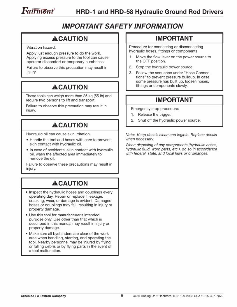
Note: Keep decals clean and legible. Replace decals when necessary.
When disposing of any components (hydraulic hoses, hydraulic fluid, worn parts, etc.), do so in accordance with federal, state, and local laws or ordinances.
Procedure for connecting or disconnecting hydraulic hoses, fittings or components:
1. Move the flow lever on the power source to the OFF position.
2. Stop the hydraulic power source.
3. Follow the sequence under “Hose Connec-tions” to prevent pressure buildup. In case some pressure has built up, loosen hoses, fittings or components slowly.
Emergency stop procedure:
1. Release the trigger.
2. Shut off the hydraulic power source.
Vibration hazard:
Apply just enough pressure to do the work. Applying excess pressure to the tool can cause operator discomfort or temporary numbness.
Failure to observe this precaution may result in injury.
These tools can weigh more than 25 kg (55 lb) and require two persons to lift and transport.
Failure to observe this precaution may result in injury.
Hydraulic oil can cause skin irritation.
• Handle the tool and hoses with care to prevent skin contact with hydraulic oil.
• In case of accidental skin contact with hydraulic oil, wash the affected area immediately to remove the oil.
Failure to observe these precautions may result in injury.
• Inspect the hydraulic hoses and couplings every operating day. Repair or replace if leakage, cracking, wear, or damage is evident. Damaged hoses or couplings may fail, resulting in injury or property damage.
• Use this tool for manufacturer’s intended purpose only. Use other than that which is described in this manual may result in injury or property damage.
• Make sure all bystanders are clear of the work area when handling, starting, and operating the tool. Nearby personnel may be injured by flying or falling debris or by flying parts in the event of a tool malfunction.
HRD-1 and HRD-58 Hydraulic Ground Rod Drivers
Greenlee / A Textron Company 6 4455 Boeing Dr. • Rockford, IL 61109-2988 USA • 815-397-7070
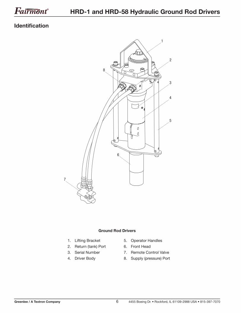
Identification
Ground Rod Drivers
1. Lifting Bracket
2. Return (tank) Port
3. Serial Number
4. Driver Body
5. Operator Handles
6. Front Head
7. Remote Control Valve
8. Supply (pressure) Port
1
3
2
4
5
8
7
6
HRD-1 and HRD-58 Hydraulic Ground Rod Drivers
Greenlee / A Textron Company 7 4455 Boeing Dr. • Rockford, IL 61109-2988 USA • 815-397-7070
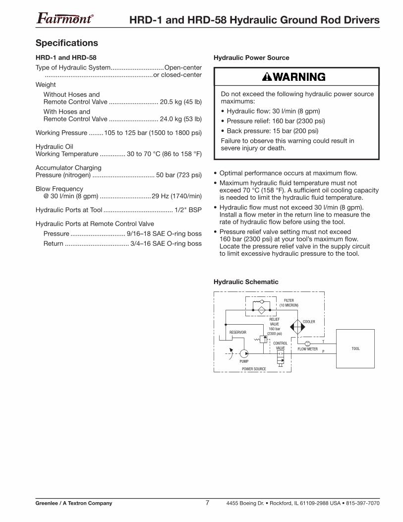
• Optimal performance occurs at maximum flow.
• Maximum hydraulic fluid temperature must not exceed 70 °C (158 °F). A sufficient oil cooling capacity is needed to limit the hydraulic fluid temperature.
• Hydraulic flow must not exceed 30 l/min (8 gpm). Install a flow meter in the return line to measure the rate of hydraulic flow before using the tool.
• Pressure relief valve setting must not exceed 160 bar (2300 psi) at your tool’s maximum flow. Locate the pressure relief valve in the supply circuit to limit excessive hydraulic pressure to the tool.
FILTER(10 MICRON)
COOLERRELIEFVALVE
160 bar(2300 psi)
CONTROLVALVE FLOW METER
T
PTOOL
RESERVOIR
PUMP
POWER SOURCE
Hydraulic Schematic
Do not exceed the following hydraulic power source maximums:
• Hydraulic flow: 30 l/min (8 gpm)
• Pressure relief: 160 bar (2300 psi)
• Back pressure: 15 bar (200 psi)
Failure to observe this warning could result in severe injury or death.
Specifications
HRD-1 and HRD-58
Type of Hydraulic System .............................Open-center ...........................................................or closed-center
Weight
Without Hoses and Remote Control Valve ........................... 20.5 kg (45 lb)
With Hoses and Remote Control Valve ........................... 24.0 kg (53 lb)
Working Pressure ........105 to 125 bar (1500 to 1800 psi)
Hydraulic Oil Working Temperature .............. 30 to 70 °C (86 to 158 °F)
Accumulator Charging Pressure (nitrogen) .................................. 50 bar (723 psi)
Blow Frequency @ 30 l/min (8 gpm) ............................29 Hz (1740/min)
Hydraulic Ports at Tool ...................................... 1/2" BSP
Hydraulic Ports at Remote Control Valve
Pressure .............................. 9/16–18 SAE O-ring boss
Return ................................... 3/4–16 SAE O-ring boss
Hydraulic Power Source
HRD-1 and HRD-58 Hydraulic Ground Rod Drivers
Greenlee / A Textron Company 8 4455 Boeing Dr. • Rockford, IL 61109-2988 USA • 815-397-7070
Specifications (cont’d)
Recommended Hydraulic Fluid
Viscosity
Ideal ..........................................................20 to 40 cSt
Allowable ...............................................15 to 1000 cSt
Viscosity Index ................................................... Min. 100
Standard mineral or synthetic oil can be used.
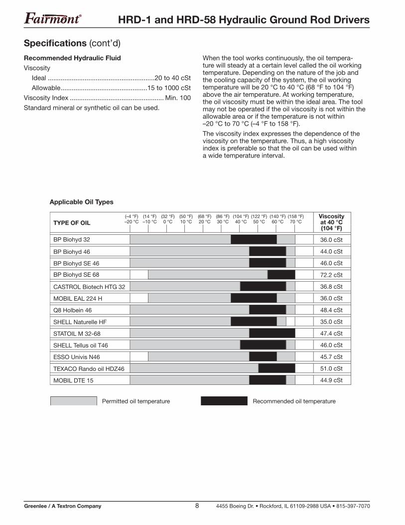
Applicable Oil Types
TYPE OF OILViscosityat 40 °C(104 °F)
BP Biohyd 32 36.0 cSt
BP Biohyd 46 44.0 cSt
BP Biohyd SE 46 46.0 cSt
BP Biohyd SE 68 72.2 cSt
CASTROL Biotech HTG 32 36.8 cSt
MOBIL EAL 224 H 36.0 cSt
Q8 Holbein 46 48.4 cSt
SHELL Naturelle HF 35.0 cSt
STATOIL M 32-68 47.4 cSt
SHELL Tellus oil T46 46.0 cSt
ESSO Univis N46 45.7 cSt
TEXACO Rando oil HDZ46 51.0 cSt
MOBIL DTE 15 44.9 cSt
Permitted oil temperature Recommended oil temperature
(–4 °F)–20 °C
(14 °F)–10 °C
(32 °F)0 °C
(50 °F)10 °C
(68 °F)20 °C
(86 °F)30 °C
(104 °F)40 °C
(140 °F)60 °C
(158 °F)70 °C
(122 °F)50 °C
When the tool works continuously, the oil tempera-ture will steady at a certain level called the oil working temperature. Depending on the nature of the job and the cooling capacity of the system, the oil working temperature will be 20 °C to 40 °C (68 °F to 104 °F) above the air temperature. At working temperature, the oil viscosity must be within the ideal area. The tool may not be operated if the oil viscosity is not within the allowable area or if the temperature is not within –20 °C to 70 °C (–4 °F to 158 °F).
The viscosity index expresses the dependence of the viscosity on the temperature. Thus, a high viscosity index is preferable so that the oil can be used within a wide temperature interval.
HRD-1 and HRD-58 Hydraulic Ground Rod Drivers
Greenlee / A Textron Company 9 4455 Boeing Dr. • Rockford, IL 61109-2988 USA • 815-397-7070
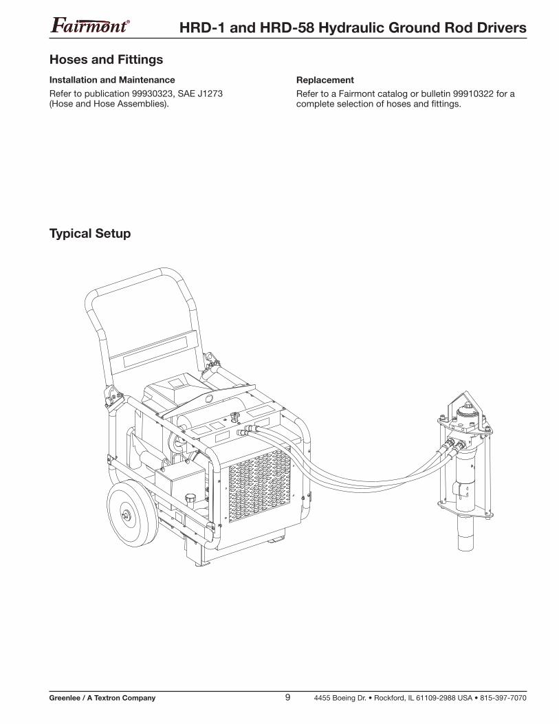
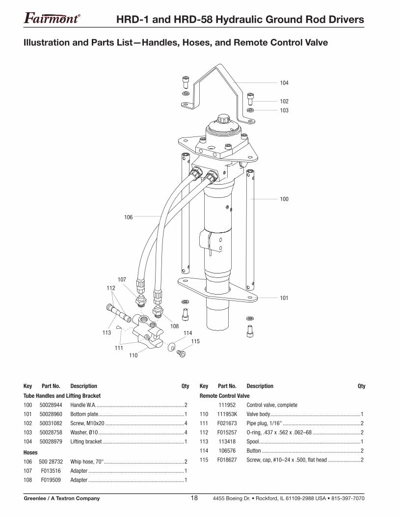
Hoses and Fittings
Installation and Maintenance
Refer to publication 99930323, SAE J1273 (Hose and Hose Assemblies).
Typical Setup
Replacement
Refer to a Fairmont catalog or bulletin 99910322 for a complete selection of hoses and fittings.
HRD-1 and HRD-58 Hydraulic Ground Rod Drivers
Greenlee / A Textron Company 10 4455 Boeing Dr. • Rockford, IL 61109-2988 USA • 815-397-7070
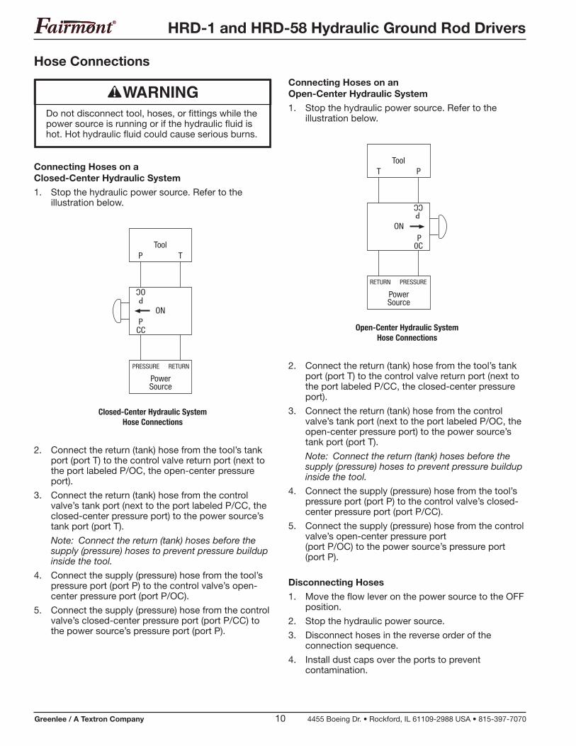
Hose Connections
Do not disconnect tool, hoses, or fittings while the power source is running or if the hydraulic fluid is hot. Hot hydraulic fluid could cause serious burns.
Connecting Hoses on a Closed-Center Hydraulic System
1. Stop the hydraulic power source. Refer to the illustration below.
P TTool
ONP
CC
POC
PRESSURE RETURN
PowerSource
Closed-Center Hydraulic System Hose Connections
2. Connect the return (tank) hose from the tool’s tank port (port T) to the control valve return port (next to the port labeled P/OC, the open-center pressure port).
3. Connect the return (tank) hose from the control valve’s tank port (next to the port labeled P/CC, the closed-center pressure port) to the power source’s tank port (port T).
Note: Connect the return (tank) hoses before the supply (pressure) hoses to prevent pressure buildup inside the tool.
4. Connect the supply (pressure) hose from the tool’s pressure port (port P) to the control valve’s open-center pressure port (port P/OC).
5. Connect the supply (pressure) hose from the control valve’s closed-center pressure port (port P/CC) to the power source’s pressure port (port P).
Connecting Hoses on an Open-Center Hydraulic System
1. Stop the hydraulic power source. Refer to the illustration below.
T PTool
ONP
0C
PCC
RETURN PRESSURE
PowerSource
Open-Center Hydraulic System Hose Connections
2. Connect the return (tank) hose from the tool’s tank port (port T) to the control valve return port (next to the port labeled P/CC, the closed-center pressure port).
3. Connect the return (tank) hose from the control valve’s tank port (next to the port labeled P/OC, the open-center pressure port) to the power source’s tank port (port T).
Note: Connect the return (tank) hoses before the supply (pressure) hoses to prevent pressure buildup inside the tool.
4. Connect the supply (pressure) hose from the tool’s pressure port (port P) to the control valve’s closed-center pressure port (port P/CC).
5. Connect the supply (pressure) hose from the control valve’s open-center pressure port (port P/OC) to the power source’s pressure port (port P).
Disconnecting Hoses
1. Move the flow lever on the power source to the OFF position.
2. Stop the hydraulic power source.
3. Disconnect hoses in the reverse order of the connection sequence.
4. Install dust caps over the ports to prevent contamination.
HRD-1 and HRD-58 Hydraulic Ground Rod Drivers
Greenlee / A Textron Company 11 4455 Boeing Dr. • Rockford, IL 61109-2988 USA • 815-397-7070
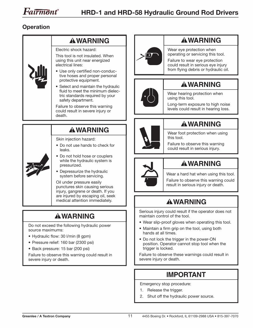
Operation
Skin injection hazard:
• Do not use hands to check for leaks.
• Do not hold hose or couplers while the hydraulic system is pressurized.
• Depressurize the hydraulic system before servicing.
Oil under pressure easily punctures skin causing serious injury, gangrene or death. If you are injured by escaping oil, seek medical attention immediately.
Do not exceed the following hydraulic power source maximums:
• Hydraulic flow: 30 l/min (8 gpm)
• Pressure relief: 160 bar (2300 psi)
• Back pressure: 15 bar (200 psi)
Failure to observe this warning could result in severe injury or death.
Wear eye protection when operating or servicing this tool.
Failure to wear eye protection could result in serious eye injury from flying debris or hydraulic oil.
Wear hearing protection when using this tool.
Long-term exposure to high noise levels could result in hearing loss.
Wear foot protection when using this tool.
Failure to observe this warning could result in serious injury.
Serious injury could result if the operator does not maintain control of the tool.
• Wear slip-proof gloves when operating this tool.
• Maintain a firm grip on the tool, using both hands at all times.
• Do not lock the trigger in the power-ON position. Operator cannot stop tool when the trigger is locked.
Failure to observe these warnings could result in severe injury or death.
Emergency stop procedure:
1. Release the trigger.
2. Shut off the hydraulic power source.
Electric shock hazard:
This tool is not insulated. When using this unit near energized electrical lines:
• Use only certified non-conduc-tive hoses and proper personal protective equipment.
• Select and maintain the hydraulic fluid to meet the minimum dielec-tric standards required by your safety department.
Failure to observe this warning could result in severe injury or death.
Wear a hard hat when using this tool.
Failure to observe this warning could result in serious injury or death.
HRD-1 and HRD-58 Hydraulic Ground Rod Drivers
Greenlee / A Textron Company 12 4455 Boeing Dr. • Rockford, IL 61109-2988 USA • 815-397-7070
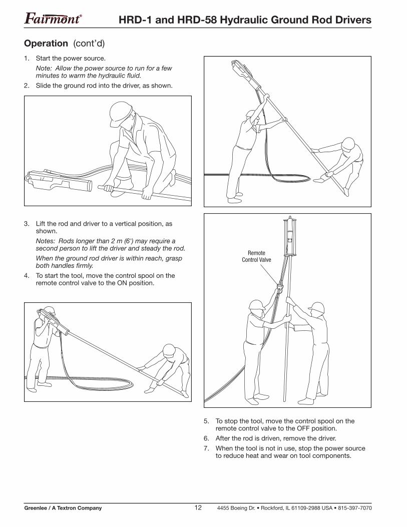
Operation (cont’d)
1. Start the power source.
Note: Allow the power source to run for a few minutes to warm the hydraulic fluid.
2. Slide the ground rod into the driver, as shown.
5. To stop the tool, move the control spool on the remote control valve to the OFF position.
6. After the rod is driven, remove the driver.
7. When the tool is not in use, stop the power source to reduce heat and wear on tool components.
3. Lift the rod and driver to a vertical position, as shown.
Notes: Rods longer than 2 m (6') may require a second person to lift the driver and steady the rod.
When the ground rod driver is within reach, grasp both handles firmly.
4. To start the tool, move the control spool on the remote control valve to the ON position.
RemoteControl Valve
HRD-1 and HRD-58 Hydraulic Ground Rod Drivers
Greenlee / A Textron Company 13 4455 Boeing Dr. • Rockford, IL 61109-2988 USA • 815-397-7070
Use this maintenance schedule to maximize the tool’s service life.
Note: Keep decals clean and legible. Replace decals when necessary.
When disposing of any components (hydraulic hoses, hydraulic fluid, worn parts, etc.), do so in accordance with federal, state, and local laws or ordinances.
Daily
1. Wipe all tool surfaces clean.
2. Inspect the hydraulic hoses and fittings for signs of leaks, cracks, wear, or damage. Replace if necessary.
3. Install dust caps over the hydraulic ports when the tool is disconnected.
4. Apply a light oil to all moving parts.
Monthly
Perform a thorough inspection of the hydraulic hoses and fittings as described in publication 99930323, SAE J1273 (Hose and Hose Assemblies).
Annually
If required by your organization, have the tool inspected by an authorized Fairmont service center.
Storage
If the tool requires long-term storage, protect the striking piston against corrosion. Press the striking piston to its upper position (through the anvil bushing). As the quick-release couplings are blocked when disassembled, the striking piston must be pressed upward with the hoses mounted but the power source turned off.
Maintenance
Do not change accessories, inspect, adjust or clean tool when it is connected to a power source.
Accidental startup could result in serious injury or death.
Wear eye protection when operating or servicing this tool.
Failure to wear eye protection could result in serious eye injury from flying debris or hydraulic oil.
HRD-1 and HRD-58 Hydraulic Ground Rod Drivers
Greenlee / A Textron Company 14 4455 Boeing Dr. • Rockford, IL 61109-2988 USA • 815-397-7070
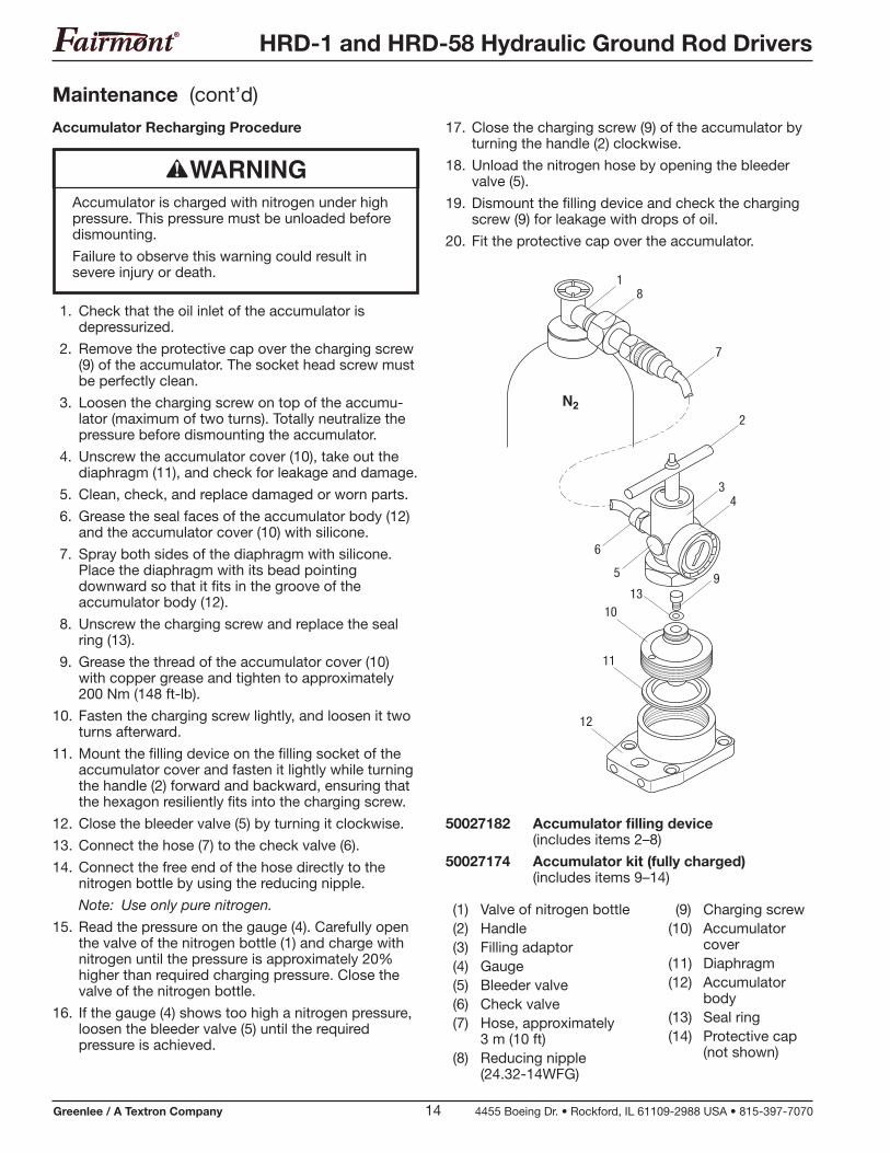
Maintenance (cont’d)
1. Check that the oil inlet of the accumulator is depressurized.
2. Remove the protective cap over the charging screw (9) of the accumulator. The socket head screw must be perfectly clean.
3. Loosen the charging screw on top of the accumu-lator (maximum of two turns). Totally neutralize the pressure before dismounting the accumulator.
4. Unscrew the accumulator cover (10), take out the diaphragm (11), and check for leakage and damage.
5. Clean, check, and replace damaged or worn parts.
6. Grease the seal faces of the accumulator body (12) and the accumulator cover (10) with silicone.
7. Spray both sides of the diaphragm with silicone. Place the diaphragm with its bead pointing downward so that it fits in the groove of the accumulator body (12).
8. Unscrew the charging screw and replace the seal ring (13).
9. Grease the thread of the accumulator cover (10) with copper grease and tighten to approximately 200 Nm (148 ft-lb).
10. Fasten the charging screw lightly, and loosen it two turns afterward.
11. Mount the filling device on the filling socket of the accumulator cover and fasten it lightly while turning the handle (2) forward and backward, ensuring that the hexagon resiliently fits into the charging screw.
12. Close the bleeder valve (5) by turning it clockwise.
13. Connect the hose (7) to the check valve (6).
14. Connect the free end of the hose directly to the nitrogen bottle by using the reducing nipple.
Note: Use only pure nitrogen.
15. Read the pressure on the gauge (4). Carefully open the valve of the nitrogen bottle (1) and charge with nitrogen until the pressure is approximately 20% higher than required charging pressure. Close the valve of the nitrogen bottle.
16. If the gauge (4) shows too high a nitrogen pressure, loosen the bleeder valve (5) until the required pressure is achieved.
Accumulator is charged with nitrogen under high pressure. This pressure must be unloaded before dismounting.
Failure to observe this warning could result in severe injury or death.
Accumulator Recharging Procedure 17. Close the charging screw (9) of the accumulator by turning the handle (2) clockwise.
18. Unload the nitrogen hose by opening the bleeder valve (5).
19. Dismount the filling device and check the charging screw (9) for leakage with drops of oil.
20. Fit the protective cap over the accumulator.
(9) Charging screw(10) Accumulator
cover(11) Diaphragm(12) Accumulator
body(13) Seal ring(14) Protective cap
(not shown)
HRD-1 and HRD-58 Hydraulic Ground Rod Drivers
Greenlee / A Textron Company 15 4455 Boeing Dr. • Rockford, IL 61109-2988 USA • 815-397-7070
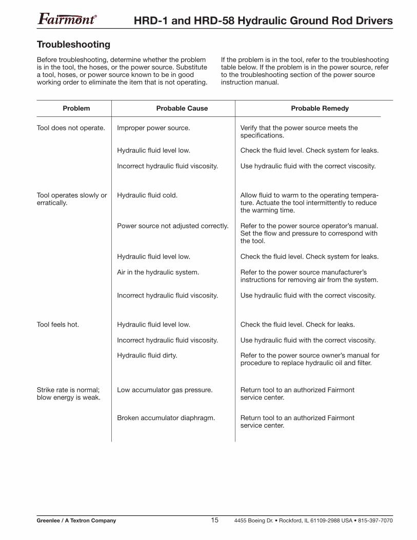
Problem Probable Cause Probable Remedy
Troubleshooting
Before troubleshooting, determine whether the problem is in the tool, the hoses, or the power source. Substitute a tool, hoses, or power source known to be in good working order to eliminate the item that is not operating.
If the problem is in the tool, refer to the troubleshooting table below. If the problem is in the power source, refer to the troubleshooting section of the power source instruction manual.
Tool does not operate. Verify that the power source meets the specifications.
Improper power source.
Check the fluid level. Check system for leaks.Hydraulic fluid level low.
Use hydraulic fluid with the correct viscosity.Incorrect hydraulic fluid viscosity.
Hydraulic fluid cold. Allow fluid to warm to the operating tempera-ture. Actuate the tool intermittently to reduce the warming time.
Tool operates slowly or erratically.
Hydraulic fluid level low. Check the fluid level. Check system for leaks.
Power source not adjusted correctly. Refer to the power source operator’s manual. Set the flow and pressure to correspond with the tool.
Air in the hydraulic system. Refer to the power source manufacturer’s instructions for removing air from the system.
Incorrect hydraulic fluid viscosity. Use hydraulic fluid with the correct viscosity.
Tool feels hot. Hydraulic fluid level low. Check the fluid level. Check for leaks.
Incorrect hydraulic fluid viscosity. Use hydraulic fluid with the correct viscosity.
Hydraulic fluid dirty. Refer to the power source owner’s manual for procedure to replace hydraulic oil and filter.
Strike rate is normal; blow energy is weak.
Low accumulator gas pressure.
Broken accumulator diaphragm.
Return tool to an authorized Fairmont service center.
Return tool to an authorized Fairmont service center.
HRD-1 and HRD-58 Hydraulic Ground Rod Drivers
Greenlee / A Textron Company 16 4455 Boeing Dr. • Rockford, IL 61109-2988 USA • 815-397-7070
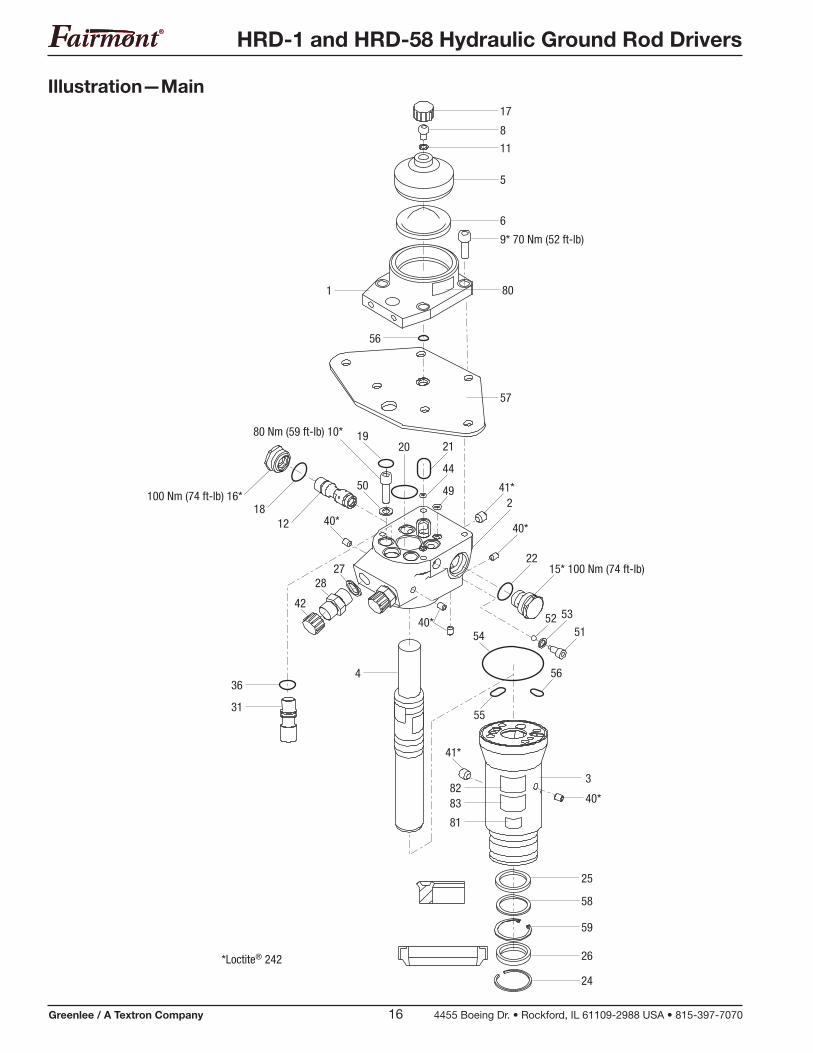
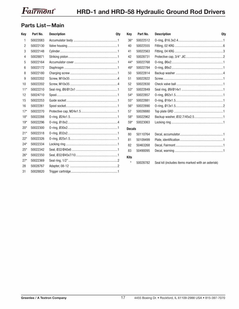
Illustration—Main
24
26
59
58
25
40*
382
80
83
81
2120
44
49
40*
17
8
11
5
57
6
9* 70 Nm (52 ft-lb)
19
50
80 Nm (59 ft-lb) 10*
41*2
40*
52 53
51
2215* 100 Nm (74 ft-lb)
36
31
2728
42
40*
4
41*
56
55
*Loctite® 242
54
100 Nm (74 ft-lb) 16*18
12
56
1
HRD-1 and HRD-58 Hydraulic Ground Rod Drivers
Greenlee / A Textron Company 17 4455 Boeing Dr. • Rockford, IL 61109-2988 USA • 815-397-7070