Manufactured By H&S MANUFACTURING CO.,INC. P.O. BOX 768 (715) 387-3414 FAX (715) 384-5463 MARSHFIELD, WISCONSIN 54449 HSMFG0814 Part #59745 HP 425/550 MANURE SPREADER MANURE SPREADER MANURE SPREADER MANURE SPREADER MANURE SPREADER OPERA OPERA OPERA OPERA OPERAT T TOR’S MANU OR’S MANU OR’S MANU OR’S MANU OR’S MANUAL AL AL AL AL Revision #04 425 Starting Serial # 514315 550 Starting Serial # 515194 WARNING READ AND UNDERSTAND THIS MANUAL BEFORE OPERATING THIS EQUIPMENT. UNSAFE OPERATION OR MAINTENANCE OF THIS EQUIPMENT CAN RESULT IN SERIOUS INJURY OR DEATH.
� Manure spreader was not damaged in shipment. Check for dents and loose or missing
parts. Report damage immediately to H&S Manufacturing Co., Inc.
� All bolts and fasteners are tight.
� Manure spreader has been correctly assembled according to instructions in this manual.
� All grease fittings have been lubricated. Gearbox is filled to proper level.
� Hoses and fittings are properly attached and there are no visible leaks.
� Guards and shields are secure.
� Wheels are properly mounted to torque specifications.
� Tires are inflated to correct pressure.
� Drive chain tension and alignment is correct.
� Decals are in place and legible.
H&S DEALER PRE-DELIVERY CHECK LISTAFTER COMPLETION, DEALER SHOULD REMOVE AND RETAIN FOR RECORDS
After the Manure Spreader has been completely set-up, check to be certain it is in correct operating orderbefore delivering to the customer. The following is a list of points to inspect. Check off each item as youhave made the proper adjustments and found the item operating satisfactorily.
Connect the manure spreader onto a proper horsepower tractor and attach the PTO andconnect the lights. Connect the hydraulic hoses to the tractor remote outlets. Run the manurespreader and make sure all components operate properly.
� PTO guard turns freely.
� Hydraulic end gate operates smoothly.
� Hydraulic pusher operates smoothly.
� Hydraulic system does not leak under pressure.
� Lights and wiring functioning properly.
� Implement and all components are functioning properly.
(Rem
ove
Dea
ler
File
Cop
y A
t Per
fora
tion)
Serial #
Dealer’s Name
Signature of Pre-Delivery Inspector
Inspection Date
Model Number
-3-
Intentionally Left Blank
-4-
This check list that follows is an important reminder of valuable information that should be passedon to the customer at the time this Manure Spreader is delivered.
Check off each item as you explain it to the customer.
This delivery check list, when properly filled out and signed assures the customer that thePre-delivery service was satisfactorily performed.
Explain to the customer that the pre-delivery inspection was made.
Explain to the customer all the safety precautions they must excercise when operatingthis unit.
Explain recommended loads for different types of materials.
Explain to customer that regular lubrication is required for proper operation and long life ofmachine.
Show customer the lubrication section of Owner’s Manual.
Give the customer Owner’s Manual and make sure they read and understand all operatingand service instructions.
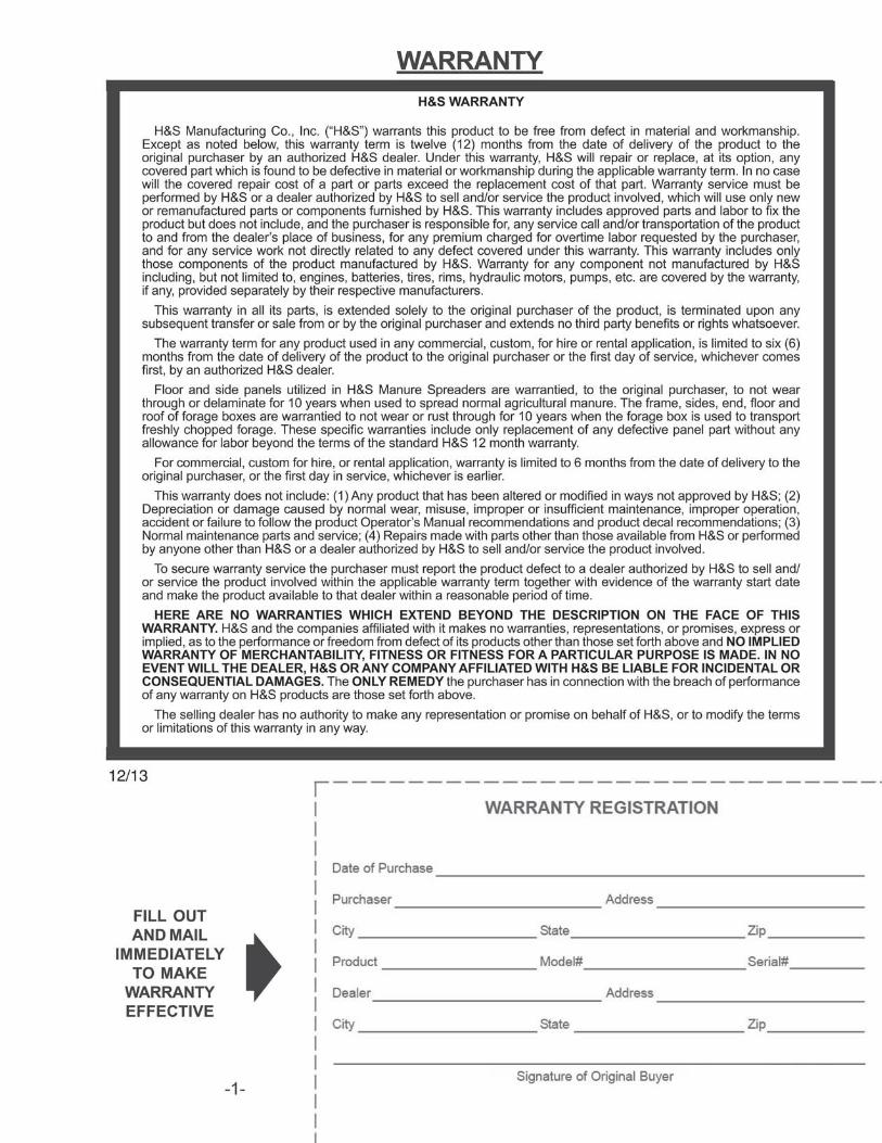
� Have the customer sign a completed “Warranty Registration”, and mail it.
DEALER DELIVERY CHECK LIST
�
(Rem
ove
Dea
ler
File
Cop
y A
t Per
fora
tion)
AFTER COMPLETION, DEALER SHOULD REMOVE AND RETAIN FOR RECORDS
�
�
�
�
�
Date Delivered
Dealer’s Name
By
Signature of Original Buyer
Note: Warranty is not valid until warranty card is completed and returned to H&S Mfg. Co., Inc.
-5-
Intentionally Left Blank
-6-
-7-
BEALERT!
YOUR SAFETYIS INVOLVED.
THIS SYMBOL IS USED THROUGHOUT THIS BOOK WHENEVER YOUR PERSONAL SAFETYIS INVOLVED. TAKE TIME TO BE CAREFUL. REMEMBER: THE CAREFUL OPERATOR IS THEBEST OPERATOR. MOST ACCIDENTS ARE CAUSED BY HUMAN ERROR. CERTAINPRECAUTIONS MUST BE OBSERVED TO PREVENT THE POSSIBILITY OF INJURY ORDAMAGE.
SAFETY INFORMATION
H&S MANUFACTURING CO., INC.
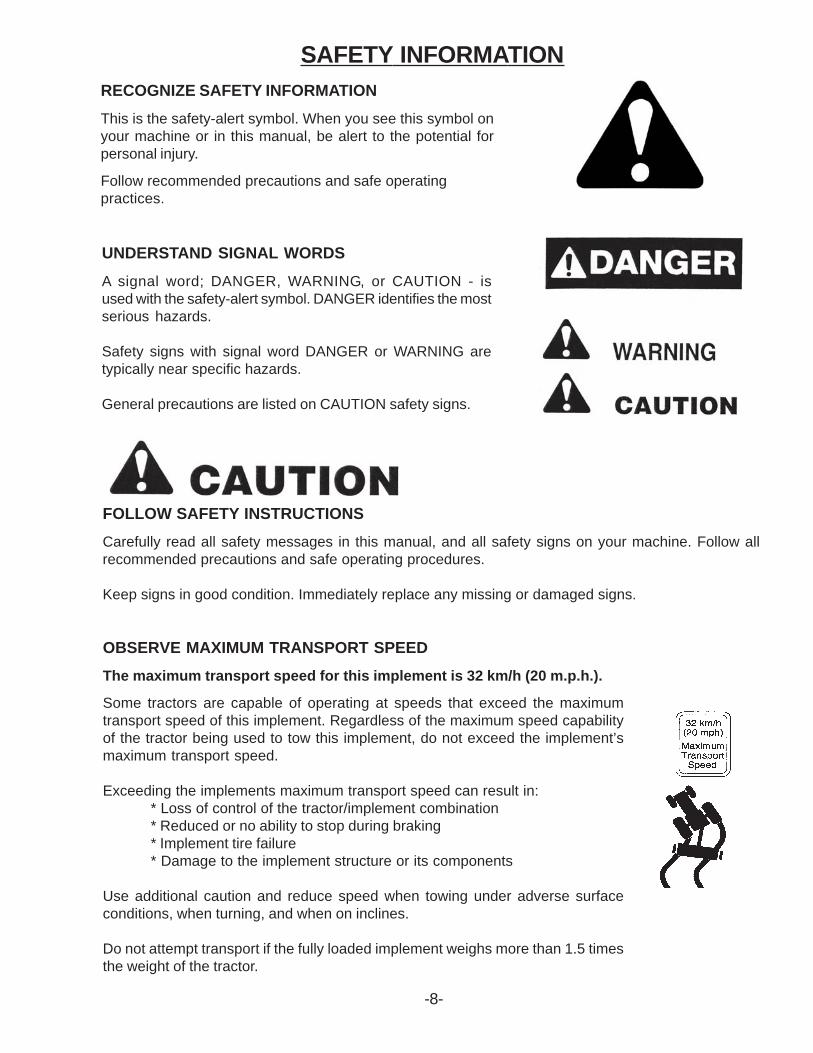
RECOGNIZE SAFETY INFORMATION
This is the safety-alert symbol. When you see this symbol onyour machine or in this manual, be alert to the potential forpersonal injury.
Follow recommended precautions and safe operatingpractices.
UNDERSTAND SIGNAL WORDS
A signal word; DANGER, WARNING, or CAUTION - isused with the safety-alert symbol. DANGER identifies the mostserious hazards.
Safety signs with signal word DANGER or WARNING aretypically near specific hazards.
General precautions are listed on CAUTION safety signs.
FOLLOW SAFETY INSTRUCTIONS
Carefully read all safety messages in this manual, and all safety signs on your machine. Follow allrecommended precautions and safe operating procedures.
Keep signs in good condition. Immediately replace any missing or damaged signs.
-8-
OBSERVE MAXIMUM TRANSPORT SPEED
The maximum transport speed for this implement is 32 km/h (20 m.p.h.).
Some tractors are capable of operating at speeds that exceed the maximumtransport speed of this implement. Regardless of the maximum speed capabilityof the tractor being used to tow this implement, do not exceed the implement’smaximum transport speed.
Exceeding the implements maximum transport speed can result in:* Loss of control of the tractor/implement combination* Reduced or no ability to stop during braking* Implement tire failure* Damage to the implement structure or its components
Use additional caution and reduce speed when towing under adverse surfaceconditions, when turning, and when on inclines.
Do not attempt transport if the fully loaded implement weighs more than 1.5 timesthe weight of the tractor.
SAFETY INFORMATION
-9-
SAFETY DECALS
-10-
SAFETY DECALS
-11-
SAFETY DECALS
Study The Above Safety RulesATTENTION - BE ALERT - YOUR SAFETY IS INVOLVED
BEFORE YOU ATTEMPT TO OPERATE THIS EQUIPMENT, READ AND STUDY THE FOLLOWINGINFORMATION. IN ADDITION, MAKE SURE THAT EVERY INDIVIDUAL WHO OPERATES OR WORKSWITH THIS EQUIPMENT, WHETHER FAMILY MEMBER OR EMPLOYEE, IS FAMILIAR WITH THESESAFTEY PRECAUTIONS. KNOW HOW TO STOP UNLOADING MECHANISM BEFORE STARTING IT.
If the machine becomes clogged, disengage the PTO. Stop the tractor engine, remove ignition key, andallow all mechanisms to stop before cleaning or working on the machine.“Never allow riders” in or on the machine.
DO NOT get off the tractor while the spreader is in operation.
DO NOT attempt to perform maintenance or repair with tractor running and PTO or hydraulic lineshooked up.
DO NOT step up on machine at any time.
NEVER manually feed material into the beaters.
DO NOT allow minors to operate or be near the machine.
DO NOT ALLOW PERSONNEL OTHER THAN THE QUALIFIED OPERATOR NEAR THE MACHINE.
Before starting tractor, be sure PTO shields turn freely and PTO is securely locked to tractor.
DO NOT clean, adjust, or lubricate the machine when any part is in operation.
Keep hands, feet, and clothing away from beaters when they are revolving.
Loose or floppy clothing should not be worn by the operator.
Be sure the machine is clear of people, tools, and other objects before engaging PTO.
DO NOT step over power take off shaft. Stay clear of PTO at all times.
NEVER start manure spreader until all guards and safety shields are secured in place.
STAY CLEAR of Hydraulic Lines. They may be under extreme pressure or heat.
H&S always takes the operator and his safety into consideration and guards exposed moving parts forhis protection. However, some areas cannot be guarded or shielded in order to assure proper operation. Inaddition, the operators manual and decals on the machine itself warn you of further danger and shouldbe read and observed closely.
-12-
TRACTOR:This operators manual uses the term “Tractor” when identifying the power source.
TO PREVENT SERIOUS INJURY OR DEATH
W A R N I N G
SAFETY INFORMATION
-13-
SET-UP & ASSEMBLY
PREPARING MANURE SPREADERThe Manure Spreader may be shipped without the wheels/tires installed.
1. Attach the wheels with tires, using the lug nuts furnished and torque the mounting hardware tothe appropriate torque.Wheel bolts should be tightened at 100 ft/lbs. of torqueon HP425 and 300 ft/lbs. of torque on HP550
2. Check the tires and inflate to the recommended pressure(425/65R-22.5 tires to 85 psi.).
3. Check for proper assembly and adjustment and make sure that all bolts are tightened.
4. Securely retighten after a few hours of operation, as bolts can loosen up on new machinery.
5. Lubricate the machine completely, check the oil level of the gearbox, fill if necessary. Check theautomatic oiler level if spreader is equipped, fill if necessary.
-14-
WARNING: Some photographs used in the following pages show guards orshields removed for clarification. Never operate machine until these guardsor shields are in proper operating position.
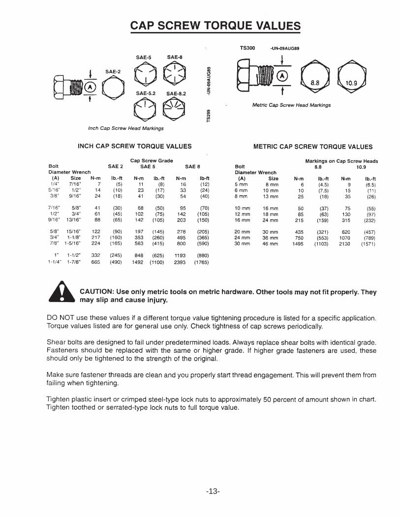
NOTE: Determine right or left side of the Manure Spreader by viewing it from the rear. If instructionsor parts lists call for hardened bolts, refer to the Cap Screw Torque Value page to identify.
-15-
TRANSPORT LIGHTING & REFLECTORS
When transporting on the highway, connect the spreader to the tractor with a lighting power cord. Thelighting system is to be connected to the 7 pin power receptacle (per SAEJ560B) on your tractor. If yourtractor is not equipped with the proper receptacle, see your tractor dealer for details. Make sure lightsare functioning properly. Regularly clean the reflective tape at the rear of the spreader. There is a holderprovided for your SMV sign.
TRANSPORTING
SAFETY CHAIN (Optional)
Follow state and local regulations regarding use of a safety chain and transport lighting when towingfarm equipment on public highways. A proper safety chain should be used to retain the safety connectionbetween the towing and towed machines, in the event of separation of the primary attaching system.Check with local law enforcement agencies for your own particular regulations. Unless otherwiseprohibited, use a slow-moving vehicle emblem. Never tow the manure spreader on a public highway at aspeed greater than 20 mph (32 kph).
1. The chain is sufficiently slack to allow turns and movements of either the tractor or the manurespreader, without placing tension on the chain.
2. The chain is of sufficient strength to hold the decoupled implement (and its load) and tow it to theshoulder.
PREPARING FOR OPERATION
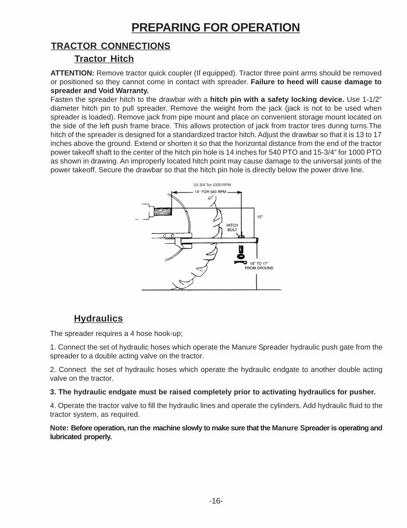
Tractor HitchATTENTION: Remove tractor quick coupler (If equipped). Tractor three point arms should be removedor positioned so they cannot come in contact with spreader. Failure to heed will cause damage tospreader and Void Warranty.Fasten the spreader hitch to the drawbar with a hitch pin with a safety locking device. Use 1-1/2”diameter hitch pin to pull spreader. Remove the weight from the jack (jack is not to be used whenspreader is loaded). Remove jack from pipe mount and place on convenient storage mount located onthe side of the left push frame brace. This allows protection of jack from tractor tires during turns.Thehitch of the spreader is designed for a standardized tractor hitch. Adjust the drawbar so that it is 13 to 17inches above the ground. Extend or shorten it so that the horizontal distance from the end of the tractorpower takeoff shaft to the center of the hitch pin hole is 14 inches for 540 PTO and 15-3/4” for 1000 PTOas shown in drawing. An improperly located hitch point may cause damage to the universal joints of thepower takeoff. Secure the drawbar so that the hitch pin hole is directly below the power drive line.
TRACTOR CONNECTIONS
-16-
15-3/4” for 1000 RPM
Hydraulics
The spreader requires a 4 hose hook-up;
1. Connect the set of hydraulic hoses which operate the Manure Spreader hydraulic push gate from thespreader to a double acting valve on the tractor.
2. Connect the set of hydraulic hoses which operate the hydraulic endgate to another double actingvalve on the tractor.
3. The hydraulic endgate must be raised completely prior to activating hydraulics for pusher.
4. Operate the tractor valve to fill the hydraulic lines and operate the cylinders. Add hydraulic fluid to thetractor system, as required.
Note: Before operation, run the machine slowly to make sure that the Manure Spreader is operating andlubricated properly.
-17-
PREPARING FOR OPERATION
Before operation, run machine slowly to make sure that the spreader is operating and lubricatedproperly.
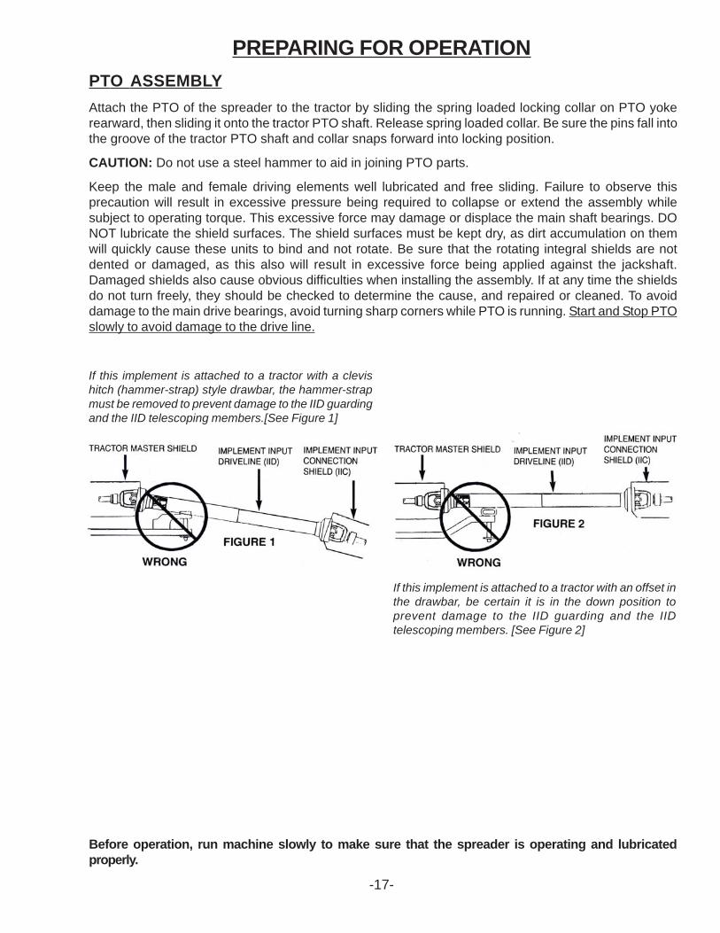
If this implement is attached to a tractor with a clevishitch (hammer-strap) style drawbar, the hammer-strapmust be removed to prevent damage to the IID guardingand the IID telescoping members.[See Figure 1]
If this implement is attached to a tractor with an offset inthe drawbar, be certain it is in the down position toprevent damage to the IID guarding and the IIDtelescoping members. [See Figure 2]
PTO ASSEMBLY
Attach the PTO of the spreader to the tractor by sliding the spring loaded locking collar on PTO yokerearward, then sliding it onto the tractor PTO shaft. Release spring loaded collar. Be sure the pins fall intothe groove of the tractor PTO shaft and collar snaps forward into locking position.
CAUTION: Do not use a steel hammer to aid in joining PTO parts.
Keep the male and female driving elements well lubricated and free sliding. Failure to observe thisprecaution will result in excessive pressure being required to collapse or extend the assembly whilesubject to operating torque. This excessive force may damage or displace the main shaft bearings. DONOT lubricate the shield surfaces. The shield surfaces must be kept dry, as dirt accumulation on themwill quickly cause these units to bind and not rotate. Be sure that the rotating integral shields are notdented or damaged, as this also will result in excessive force being applied against the jackshaft.Damaged shields also cause obvious difficulties when installing the assembly. If at any time the shieldsdo not turn freely, they should be checked to determine the cause, and repaired or cleaned. To avoiddamage to the main drive bearings, avoid turning sharp corners while PTO is running. Start and Stop PTOslowly to avoid damage to the drive line.
LOADING
Begin loading the spreader at the front end and work toward the rear until loading is completed. Loadingthis way permits the material to be spread uniformly. Loading front to rear is particularly important whenthe spreader is loaded by a mechanical loader because this type of load requires more power to spreadthan other loads.
When hauling extremely heavy materials with a large portion of dirt, it may be necessary to reduce theloadsize to prevent excessive shear bolt breakage. Never dump material onto the beater. Do not useextra sideboards. Do not overload spreader. Overloading decreases spreading effectiveness. Do notload more than 15 inches above the beater.
SPREADING
1. Engage the tractor PTO slowly. Beater is always in the engaged position, therefore, engaging thetractor PTO will automatically start the beaters.
2. Raise the hydraulic endgate by engaging the tractor hydraulics. Note: Hydraulic endgate MUSTBE RAISED COMPLETELY prior to engaging hydraulic pushgate.
3. Engage the tractor hydraulic lever into the detent position to operate the spreader hydraulic pusher.
4. The spreader pusher hydraulic hose has a restrictor in the line. It can easily be slowed down bythe tractor flow control if tractor is equipped with one. (Optional in-line flow control is available.)
5. When the spreader is empty, disengage the tractor PTO (which will stop the beater). Engage thetractor hydraulics to return the spreader push gate. When the spreader push gate is completelyretracted, engage tractor hydraulics to close hydraulic endgate.
OPERATIONEMERGENCY SHUTDOWN
If a foreign object becomes lodged in the beater area and shears theshear bolt, disengage the PTO and stop the hydraulic pusher. Stopthe tractor engine, remove the ignition key, and allow all mechanismsto stop before cleaning or working on the spreader.
WINTER OPERATION
In freezing weather, make certain that hydraulic tailgate is not frozen to the sides or on the floor of thespreader. Make sure the push gate is not frozen to the spreader floor or any lumps of manure are frozento the floor.
-18-
Be certain to disconnect all sources of power before servicing. Keep pant cuffs and loose clothing awayfrom all chains and drives as well as the other moving parts. Keep off the equipment when in use, andkeep all shields in place. Do not attempt to clean, grease or lubricate while the machine is running.
The driveline is protected by a Torque Limiter Disconnect Clutch located in the PTO at the front of thespreader. Disconnect of the clutch during operation is normally due to large frozen chunks of manure,foreign objects (rocks, chunks of wood etc.) in the manure, running the spreader push gate too fast whenunloading long straw and pen-packed material, or STARTING THE SPREADER PTO TOO QUICKLYWITH HIGH TRACTOR RPM’S. Always determine the reason for the disconnect and eliminate theproblem before re-engaging the PTO.
BEATER
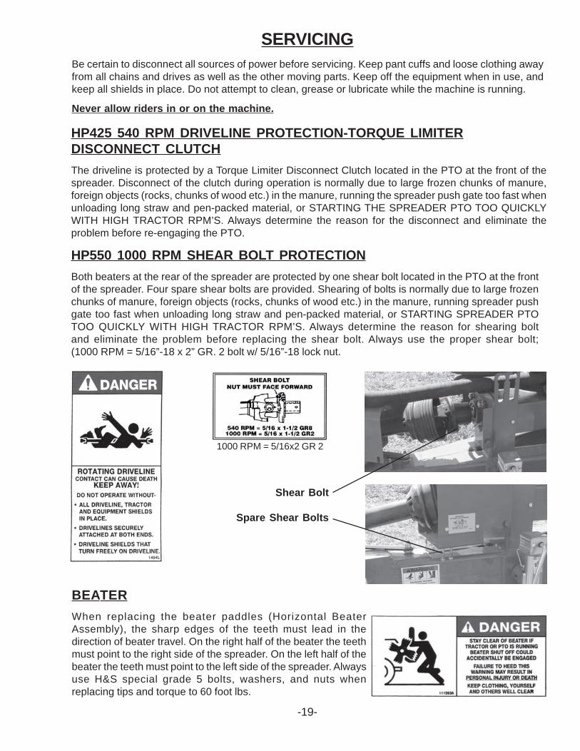
When replacing the beater paddles (Horizontal BeaterAssembly), the sharp edges of the teeth must lead in thedirection of beater travel. On the right half of the beater the teethmust point to the right side of the spreader. On the left half of thebeater the teeth must point to the left side of the spreader. Alwaysuse H&S special grade 5 bolts, washers, and nuts whenreplacing tips and torque to 60 foot lbs.
-19-
HP550 1000 RPM SHEAR BOLT PROTECTION
Both beaters at the rear of the spreader are protected by one shear bolt located in the PTO at the frontof the spreader. Four spare shear bolts are provided. Shearing of bolts is normally due to large frozenchunks of manure, foreign objects (rocks, chunks of wood etc.) in the manure, running spreader pushgate too fast when unloading long straw and pen-packed material, or STARTING SPREADER PTOTOO QUICKLY WITH HIGH TRACTOR RPM’S. Always determine the reason for shearing boltand eliminate the problem before replacing the shear bolt. Always use the proper shear bolt;(1000 RPM = 5/16”-18 x 2” GR. 2 bolt w/ 5/16”-18 lock nut.
1000 RPM = 5/16x2 GR 2
Shear Bolt
Spare Shear Bolts
TIMING OF BEATERS
The beaters must be timed so the flighting of theopposite beater is about half-way between the beaterbeing timed. To time the beaters, remove the topshield and remove the chain coupling so the beatercan be turned to the proper position. Re-connectthe chain and re-install the shield.
ADJUSTMENTS
-20-
HORIZONTAL BEATER DRIVE CHAINS
Both beater drive chains can be adjusted by loosening bolts(A) and sliding the poly tensioners toward the chain until1/2” of deflection can be obtained on the opposite side (B).Retighten the bolts (A) when deflection is obtained.
Shields Opened for Clarity
B
A
B
BE SURE ALL SHIELDS ARE SECURED INTOPLACE PRIOR TO RE-STARTING MACHINE.
WHEEL HUBS
To adjust the wheel hubs, tighten the castellated nut on the spindle to the point where there is noend-play and a slight drag on the bearings. Replace the cotter key with a new one of the correct size.
FAILURE TO FOLLOWTHE RECOMMENDEDADJUSTMENTS WILL
VOID WARRANTY.
NOTE: PERIODICALLY LUBRICATEALL ROLLER CHAINS WITH A LIGHTMACHINE OIL IF NOT EQUIPPEDWITH AN AUTOMATIC OILER.
Shields Opened for Clarity
VERTICAL BEATER DRIVE CHAINS
Vertical beater drive chains have a spring loaded tightenersystem. If chains become loose, replace the worn chainsor check if the springs are stretched out or worn, replace.
VERTICAL BEATERS
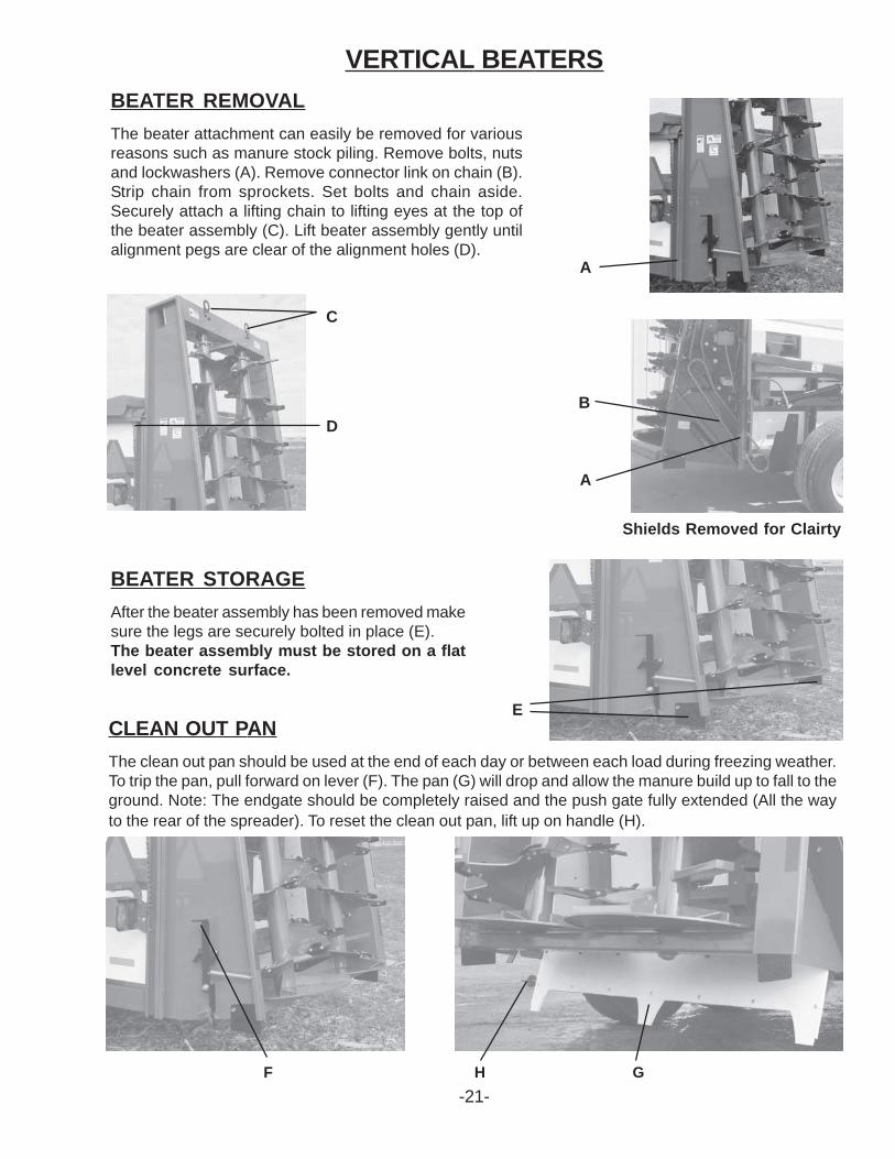
BEATER REMOVAL
The beater attachment can easily be removed for variousreasons such as manure stock piling. Remove bolts, nutsand lockwashers (A). Remove connector link on chain (B).Strip chain from sprockets. Set bolts and chain aside.Securely attach a lifting chain to lifting eyes at the top ofthe beater assembly (C). Lift beater assembly gently untilalignment pegs are clear of the alignment holes (D).
BEATER STORAGE
After the beater assembly has been removed makesure the legs are securely bolted in place (E).The beater assembly must be stored on a flatlevel concrete surface.
E
Shields Removed for Clairty
A
B
A
C
CLEAN OUT PAN
The clean out pan should be used at the end of each day or between each load during freezing weather.To trip the pan, pull forward on lever (F). The pan (G) will drop and allow the manure build up to fall to theground. Note: The endgate should be completely raised and the push gate fully extended (All the wayto the rear of the spreader). To reset the clean out pan, lift up on handle (H).
F H G
-21-
D
OPTIONAL EQUIPMENT
REAR PAN - HORIZONTAL BEATER
The rear pan shown to the right is optionalequipment on the HP425 & HP550 spreader.The rear pan option allows for an even spreadwhen light applications are needed.
-22-
-23-
The operator should become familiar with all lubrication points and establish a systematic routineto ensure complete and quick lubrication of the machine.
GREASING
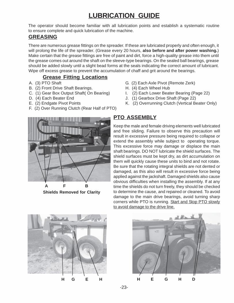
There are numerous grease fittings on the spreader. If these are lubricated properly and often enough, itwill prolong the life of the spreader. (Grease every 20 hours, also before and after power washing.)Make certain that the grease fittings are free of paint and dirt, force a high-quality grease into them untilthe grease comes out around the shaft on the sleeve-type bearings. On the sealed ball bearings, greaseshould be added slowly until a slight bead forms at the seals indicating the correct amount of lubricant.Wipe off excess grease to prevent the accumulation of chaff and grit around the bearings.
Grease Fitting LocationsA. (3) PTO Shaft G. (2) Each Axle Pivot (Remote Zerk)B. (2) Front Drive Shaft Bearings. H. (4) Each Wheel HubC. (1) Gear Box Output Shaft( On Bearing) I. (2) Each Lower Beater Bearing (Page 22)D. (4) Each Beater End J. (1) Gearbox Drive Shaft (Page 22)E. (2) Endgate Pivot Points K. (2) Overrunning Clutch (Vertical Beater Only)F. (2) Over Running Clutch (Rear Half of PTO)
A F B
H G E H
Shields Removed for Clarity
LUBRICATION GUIDE
PTO ASSEMBLY
Keep the male and female driving elements well lubricatedand free sliding. Failure to observe this precaution willresult in excessive pressure being required to collapse orextend the assembly while subject to operating torque.This excessive force may damage or displace the mainshaft bearings. DO NOT lubricate the shield surfaces. Theshield surfaces must be kept dry, as dirt accumulation onthem will quickly cause these units to bind and not rotate.Be sure that the rotating integral shields are not dented ordamaged, as this also will result in excessive force beingapplied against the jackshaft. Damaged shields also causeobvious difficulties when installing the assembly. If at anytime the shields do not turn freely, they should be checkedto determine the cause, and repaired or cleaned. To avoiddamage to the main drive bearings, avoid turning sharpcorners while PTO is running. Start and Stop PTO slowlyto avoid damage to the drive line.
H E G H D
LUBRICATION GUIDE
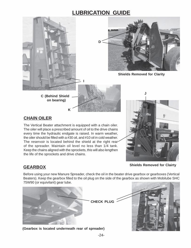
GEARBOX
Before using your new Manure Spreader, check the oil in the beater drive gearbox or gearboxes (VerticalBeaters). Keep the gearbox filled to the oil plug on the side of the gearbox as shown with Mobilube SHC75W90 (or equivilant) gear lube.
-24-
CHECK PLUG
Shields Removed for Clairty
J
I
(Gearbox is located underneath rear of spreader)
Shields Removed for Clarity
CHAIN OILER
The Vertical Beater attachment is equipped with a chain oiler.The oiler will place a prescribed amount of oil to the drive chainsevery time the hydraulic endgate is raised. In warm weather,the oiler should be filled with a #30 oil, and #10 oil in cold weather.The reservoir is located behind the shield at the right rearof the spreader. Maintain oil level no less than 1/4 tank.Keep the chains aligned with the sprockets, this will also lengthenthe life of the sprockets and drive chains.
D
K
C (Behind Shield on bearing)
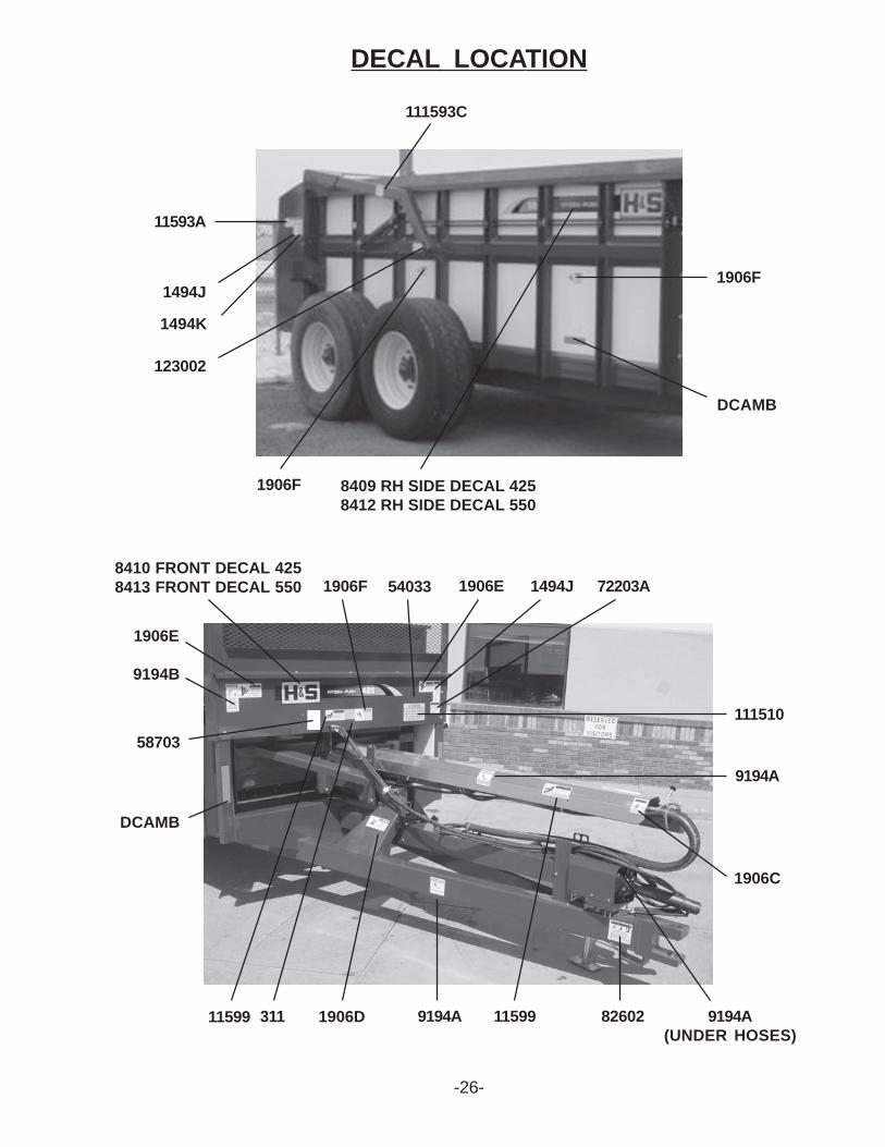
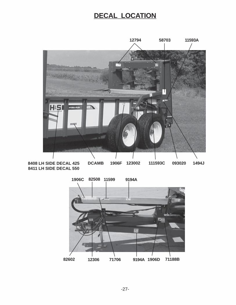
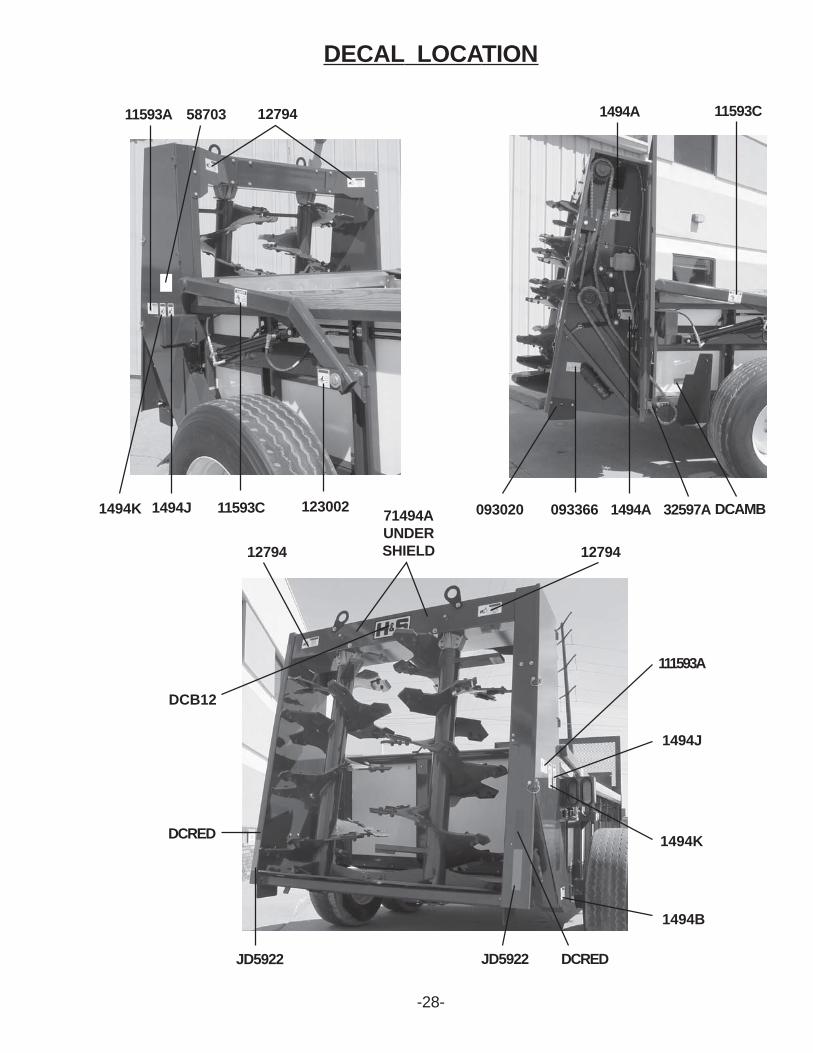
DECAL LOCATIONYour H&S Manure Spreader was manufactured with operator safety in mind. Located on the manurespreader are various decals to aid in operation, and warn of danger or caution areas. Pay close attentionto all decals on your Manure Spreader.
DO NOT REMOVE ANY OF THESE DECALS. IF DECALS ARE LOST, DAMAGED,OR IFMANURE SPREADER IS REPAINTED, REPLACE DECALS. REMEMBER: DECALS AREFOR YOUR PROTECTION AND INFORMATION.
Listed below are the decals on your Manure Spreader. These decals may be ordered individually bypart number or by ordering a complete set.
PART # QTY DESCRIPTION311 1 Patent Number1494A 2 Warning - Do Not Operate1494B 1 Warning - Do Not Remove Shields1494J 3 Warning - Do Not Clean or Work1494K 1 Warning - Do Not Remove Shields1494L 1 Danger - Rotating Driveline1906C 2 Warning - Stay Clear1906D 2 Danger - Stay Clear1906E 2 Warning - Stay Clear1906F 3 Danger - Keep Out1906F 5 Danger - Keep Out3494A 2 Remote Grease Fitting71494A 2 Warning - Do Not Remove Shields(Only on Vertical Beater Spreader)8408 1 HP425 Decal Left8409 1 HP425 Decal Right8410 1 HP425 Decal Front8411 1 HP550 Decal Left8412 1 HP550 Decal Right8413 1 HP550 Decal Front9194B 1 Danger - Never Allow Riders9194A 5 Danger - No Step11599 3 Warning - Stay Clear of Leaks12306 1 Shear Bolt12794 2 Warning - Do Not Operate(Only on Vertical Beater Spreader)32597A 1 Warning - Do Not Operate51606 1 Warning - Do Not Operate54033 1 Made in USA 3”58703 3 Danger - Stay Clear of Beater71188B 1 Jack Storage Position71706 1 Attention - Tractor 3pt Hitch72203A 1 Warning - Help Avoid Injury82508 2 Caution - Driveline Angle82602 2 Warning - Crushing Hazard093020 2 Grease Fitting (Only on Vertical Beater Spreader)93366 1 Keep Operators Manual Here111510 1 Attention Return Pusher111593A 2 Danger - Stay Clear of Beater111593C 2 Warning - Stay Clear of Endgate123002 2 Warning - Stay Clear of EndgateB12DC 1 H & S Decal (Only on Vertical Beater)DCAMB 6 Amber ReflectorDCRED 2 Red ReflectorsJD5922 2 Orange Non Reflective Decal
-25-
DECAL LOCATION
123002
111593C
1494K
1494J
11593A
1906F 8409 RH SIDE DECAL 4258412 RH SIDE DECAL 550
TROUBLE SHOOTINGWARNING:MAKE SURE THAT THE TRACTOR IS SHUT OFF AND THE SPREADER CAN NOTMOVE BEFORE SERVICING THE MANURE SPREADER. MAINTENANCE ANDREPAIR SERVICE WORK TO BE PERFORMED BY A QUALIFIED SERVICE PERSONONLY.
TROUBLE... POSSIBLE CAUSE... POSSIBLE REMEDY...
-29-
Beater Will Not Run Tractor PTO Not Turning Engage Tractor PTO