70
SEMINAR ON RCC DAMS Organized by VNCOLD Hanoi, xx September 2011 RCC DAMS WORLDWIDE AND IN VIETNAM M. Ho Ta Khanh (VNCOLD) <[email protected]>
| Date post: | 20-Oct-2015 |
| Category: |
Documents |
| Upload: | manzar-mumtaz |
| View: | 77 times |
| Download: | 8 times |

SEMINAR ON RCC DAMSOrganized by VNCOLD
Hanoi, xx September 2011
RCC DAMS WORLDWIDE AND IN VIETNAM M. Ho Ta Khanh (VNCOLD)

RCC Dams Worldwide

Design Criteria and Analysis for Gravity RCC Dams
The same as for CVC gravity dams but with different values for the parameters.
Mechanical conditions
- Strength and Sliding stability
- Deformation, settlement : FEM analysisHydraulic conditions
- Permeability- Hydraulic gradient
Adopt Vietnamese code if any, but it is possible to use all available codes or
guidelines (USA, Canada, GB, France, Germany, Russia, China, Japan, India, etc).
No code is better or worse than the others! All these codes are coherent and adopt the
same general principles (which are a simplification of the reality). They differ mainly by
the presentation and lead to very comparable results! The most important is to adopt
homogeneous parameters and criteria (global safety factors and partial safety factors
for friction, cohesion and max tensile strength). Don’t mix these codes and don’t retain,
for safety reason, the most unfavourable results!
Application with good judgment by experimented engineers is more important than the
origine of the code !

The conception of a RCC dam must be adapted to the
particularities of the RCC technique (Basic principles)
• Use as much as possible the local materials (aggregates, cementitious
materials).
• Reduce as much as possible the quantities of cementitious materials, in
particular the fly ash if it is not available near the site (< 200 km).
• Adapt the cross-section of the dam to the characteristics of the RCC, …and
not the opposite! (See examples of the Moroccan and French RCC dams).
• Each RCC dam must be optimized according to the conditions of the site
(flexibility of the design) : avoid to normalize the conception of the dam and the
composition of the RCC materials !
• Facilitate as much as possible the placement of the RCC:
Avoid if possible the structures including large openings.
Separate, if possible the location of the dam and the the powerhouse (example of Long Tan
and Salto Caxias HPP).
Select the construction equipment adapted to the rate of placement.
• If useful, the design can separate the mechanical and the watertight functions.

Design and Construction Trends in the U.S RCC Dams by F.Y.Abdo (2010)
“Perhaps the most notable development in recent RCC gravity dams in U.S.A in
the design is:
• Increasing the dam size in order to reduce the required RCC strength
provided an opportunity to use marginal on-site aggregates.
• Designing the dam to resist full hydrostatic uplift pressure eliminated the
need for foundation drains and drainage gallery (for low and medium-sized
dam).
• Eliminating the construction of a stilling basin”.
The purpose of the next slides is to illustrate these recommendations by
some examples of recent RCC dams worldwide.

Flexibility of RCC Dam Designs Very different cross-sections according to the quality of the foundation, the aggregates,
the type and content of the cementitious materials

Longtan Dam (China) 2007

Very good aspect of the downstream face
with the GEV-RCC method and an intact
core 15 m long in the dam.
No seepage in the gallery →

LONGTAN DAM
A good example of separation
between the dam and the
powerhouse.
This implementation allows a
separation between the CVC
and the RCC placements, a
continuous regular placement
of the RCC and a
commissionnig of the 3 first
units before the end of
construction of the dam
(shorter delay than for the
powerhouse).

SALTO CAXIAS (Brazil)1998
A good example of separation between the dam and the powerhouse and a
RCC without fly ash.
Same advantage as for the Long Tan Dam concerning the powerhouse
implementation.

Miel I RCC Dam (Colombia) H = 192 m V = 1 400 000 m3
A good example of a very high dam with cement contents adjusted to the
stresses and without fly ash.
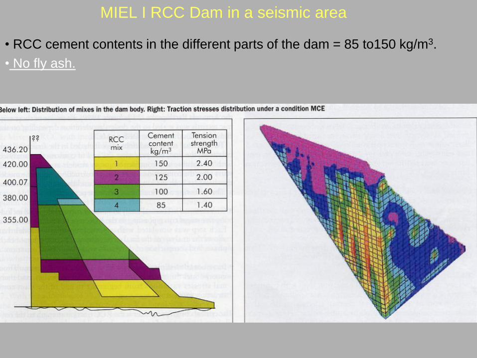
MIEL I RCC Dam in a seismic area
• RCC cement contents in the different parts of the dam = 85 to150 kg/m3.
• No fly ash.
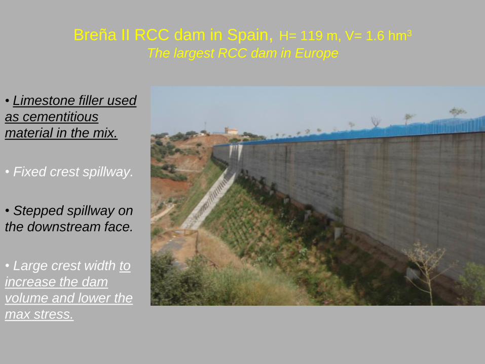
Breña II RCC dam in Spain, H= 119 m, V= 1.6 hm3
The largest RCC dam in Europe
• Limestone filler used
as cementitious
material in the mix.
• Fixed crest spillway.
• Stepped spillway on
the downstream face.
• Large crest width to
increase the dam
volume and lower the
max stress.
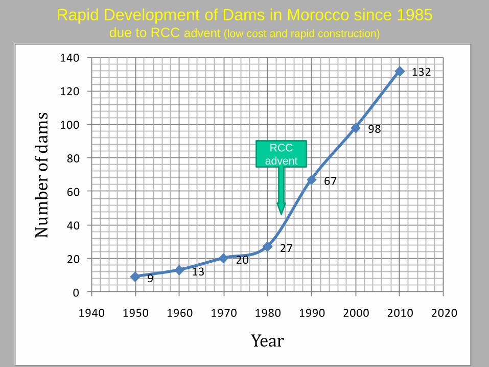
Rapid Development of Dams in Morocco since 1985 due to RCC advent (low cost and rapid construction)
913
2027
67
98
132
0
20
40
60
80
100
120
140
1940 1950 1960 1970 1980 1990 2000 2010 2020
Nu
mb
er o
f dam
s
Year
RCC
advent

The Aoulouz RCC dam in Morocco H= 79 m , V= 900 000 m3
First large RCC dam in Morocco (designed in 1987)
← 1992. End of construction
2011. Flow over the spillway →

Construction of the RCC Aoulouz dam in 1990(Note the aspect of the RCC with low cement content and no flyash)
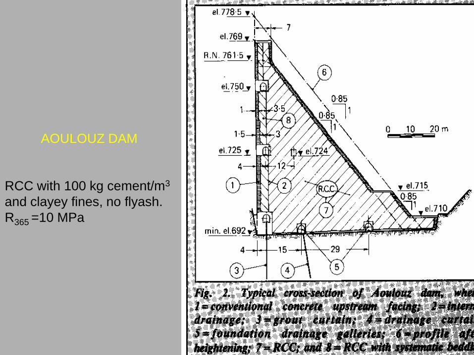
AOULOUZ DAM
RCC with 100 kg cement/m3
and clayey fines, no flyash.
R365 =10 MPa

Progress in RCC Dams in Morocco since 1987Various cross-sections of RCC dams
No flyash in all the RCC Moroccan dams

Low RCC DamsSince 1987, the Moroccan experience proved that RCC technique, in place of
masonry or CVC, is an economical solution even for low dam (< 30m).
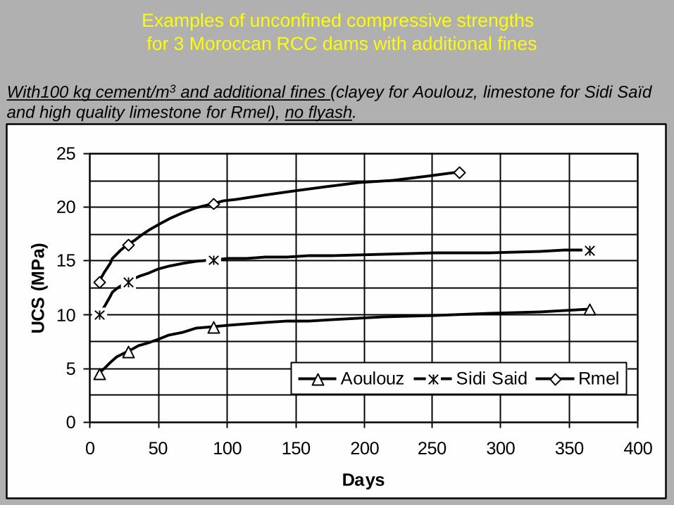
Examples of unconfined compressive strengths
for 3 Moroccan RCC dams with additional fines
With100 kg cement/m3 and additional fines (clayey for Aoulouz, limestone for Sidi Saïd
and high quality limestone for Rmel), no flyash.
0
5
10
15
20
25
0 50 100 150 200 250 300 350 400
Days
UC
S (
MP
a)
Aoulouz Sidi Said Rmel
0
5
10
15
20
25
0 50 100 150 200 250 300 350 400
Days
UC
S (
MP
a)
Aoulouz Sidi Said Rmel
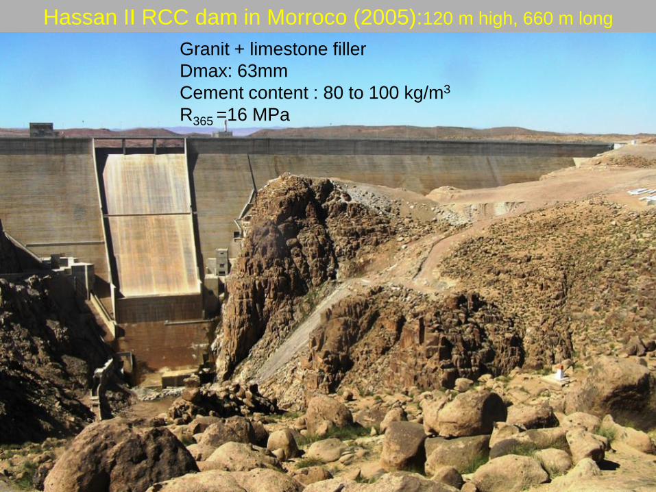
Hassan II RCC dam in Morroco (2005):120 m high, 660 m long
Granit + limestone filler
Dmax: 63mm
Cement content : 80 to 100 kg/m3
R365 =16 MPa

Hassan II RCC dam: Cross-sections and details

Wirgane RCC dam with gated spillwayH=70 m (2008)
• Cement content = 100
kg/m3 with filler.
• First placement of RCC
by the sloped layer
method. The advantages
of this method were so
evident that it was
adopted for all the next
Moroccan RCC dams,
even with medium sizes.
Note the 3m high steps
on the downstream face
corresponding to the
height of the10
continuous layers of 0.3m
high each.

The Taskourt RCC dam in Morocco (2011)
Low cement content (100 kg/m3), no flyash
… and no leakage on the downstream face !

Taskourt dam, H= 75 m, L= 416 m
Cross sections through spillway and bottom outlet

Taskourt dam : placement of the RCC by the sloped layer method

Visit of the Taskourt dam (06/06/2011)

The Tiouine RCC dam (H= 84m) in Morocco 2011
Cross sections through the spillway and the bottom outlet

Production of the inert filler and grading curves of filler and sands
The RCC (100 kg cement/m3, no fly
ash, 7% of inert filler) is placed by the
sloped layer method

Tiouine RCC material
Local fine sand and ground inert filler, without fly ash, provide sufficient density, strength
and watertightness for the dam, with the minimal cost !

Tiouine dam: Placement of the RCC
(Note the dry aspect of the RCC very easy to compact)
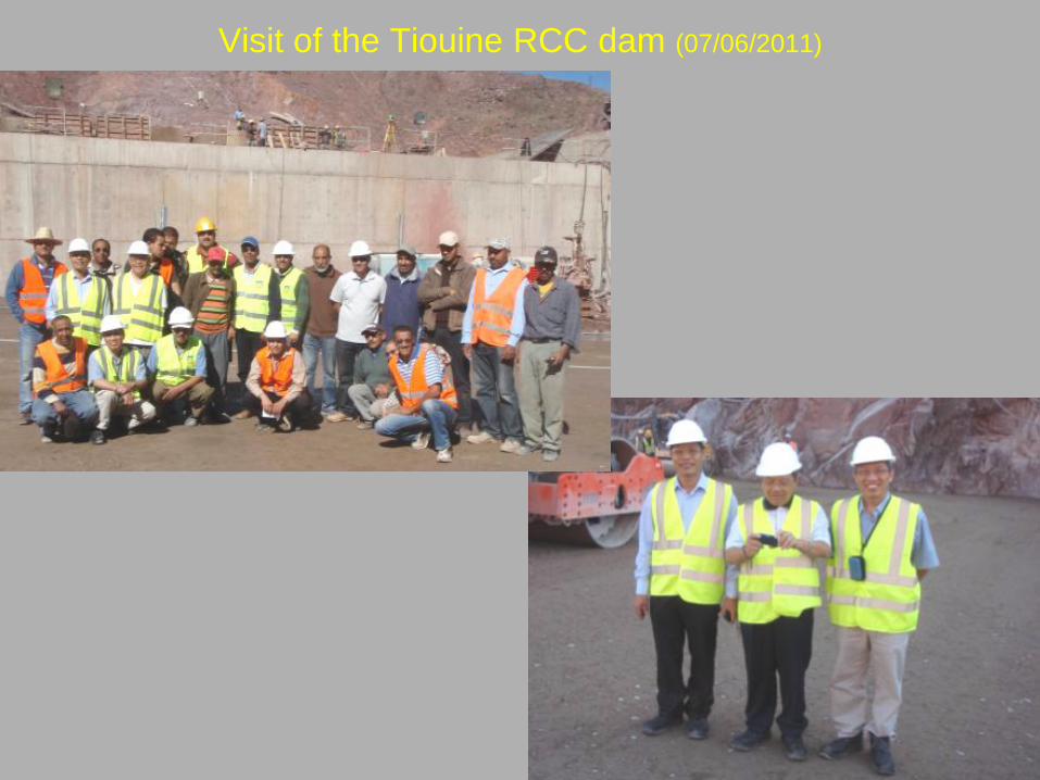
Visit of the Tiouine RCC dam (07/06/2011)

Rizzanese dam (France), H= 40.5 mAn example of RCC dam on weak foundation, low quality aggregates and low
percentage of cement, without fly ash.

Rizzanèse dam
Spreading the RCC (100 kg of cement/m3 without F.A) on the bedding mix (mortar)

Cementitious content
Comments
• Increase of «High paste RCC» is due
mainly Chinese RCC dams (China
has a lot of coal fired thermoplants
with low cost of fly ash).
• Increase of Lean RCC is due mainly
to Brazilian RCC dams (The Brazilian
RCC dams are far from thermoplants).
• High increase of the proportion of
Hardfill dams (they are not numerous,
although very interesting on
weathered foundation).
• Relative decrease of RCD (higher
cost, only adopted in Japan).
These values reflect the particularities
of the site and the conception of the
dam but not the proof of the
superiority of one technique on the
others !
1996 2006
High paste
(> 150 kg/m3
cementitious material)
43.3 % 53.4 %
Medium paste
(100 < CM < 145)
21.7 % 16.9 %
Lean RCC
(CM< 99 kg/m3)
12.7 % 13.3 %
Hardfill 0.6 % 2.9 %
RCD
(Japan)
18.5 % 12.8 %
Unknown 3.2 % 0.8 %

Cementitious materials
Comments
• Decrease of the use of (cement + low-
lime FA), which remains however the
large majority of cases.
• Increase of the use of (cement +
natural pozzolans), due to the
expansion of RCC dams to regions
where fly ash (and slag) are not
available.
• Increase of the use of (Portland
cement alone), due to the expansion
of RCC dams to regions where fly ash
(and slag) are not available.
1996 2006
Cement + low-lime
FA
66.2 % 60.8 %
Cement + high-
lime FA
1.3 % 0.9 %
Cement + ground -
granulated slag
4.5 % 5.1 %
Combination of
pozzolans (no
cement)
4.5 % 2.1 %
Cement + natural
pozzolans
7.6 % 15.3 %
Cement +
manufactured
pozzolans
2.5 % 1.2 %
Portland cement
alone
10.2 % 14.7 %
Unknown 3.2 %

Cementitious content of Brazilian Dams
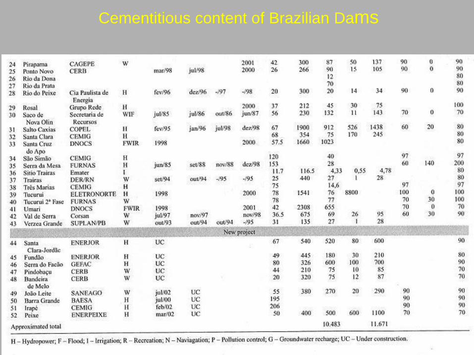
Cementitious content of Brazilian Dams
RECENT TRENDS IN RCC MATERIALS
• High or low paste content ?
All recent RCC materials are in reality «High paste content», it is more exact
to replace in this classification : «paste» by «cementitious».
• The cementitious content
The «cementitious materials» include cement and slag but also all the materials that present a «pozzolanic reactivity» (fly ash, natural or artificialpozzolan, some natural fines and rock powder, etc).
• The use of powdered aggregates
More and more used everywhere fly ash or pozzolan are too costly.
• The use of admixtures in RCC
More and more used as they can lengthen the setting time of the RCC (to
improve the bonding between the layers) and reduce the water content and
consequently the cementitious content.

Use of admixtures
Comments
- Use of a plasticizer–retarder
admixture (0.8 to 1.12 kg/m3).
- There is a reduction of VB time up to
40% for the same water content, or a
reduction of circa 10% of water
content for the same VB time.
- There is an increase of VB density.
- There is an increase of the mix
efficiency.
- For the same consistency and
compressive strength, the
cementitious content can be reduced
(15 to 30% ).
Without
admixture
With
admixture
VB (s) 67 23
Density VB
(kg/m3)
2 540 2 565
Mix efficiency
at 180 days
(MPa)/(kg/m3)
0.10 0.13
Cementitious
content in
(kg/m3)
100
120
85
80
Retarding
admixtures
Construction
under high
temperature
To avoid
cracks
(China)
Cost savings
(cement)
Brazil
Morocco
10 kg/m3
40 kg/m3

Use of powdered aggregate in Elk Creek Dam (USA)
The use of fines (in particular limestone powder) is generally very beneficial
in the RCC and allows to lower the amount of cementitious materials.

RECENT TRENDS IN RCC CONSTRUCTION (1)
• The use of conveyors: the main advantages are the possible high rate of construction
and the non pollution of the RCC layers. This use is now almost generalised for the very
large dams.
• The Sloped Layer Method (SLM): this method is at present more and more applied
when the volume of RCC to be placed on each layer is large compared with the capacity
of the batching plant.
• The bedding-mix: used generally in particular cases (cold joints between the RCC
layers, medium and low paste RCC, etc).
• The Grout Enriched RCC (GEV-RCC): more and more used for the upstream and
downstream faces of the dam and between the RCC and the CVC structures or between
the RCC and the foundation. Give very good results, if correctly applied. To obtain a
good result, it is necessary that the grout (cement+water or mortar) is poured at the base
and/or in the middle of the new layer (or in a small trench dug in this layer), before its
vibration by the needles. This technique is valid even with low cementitious RCC
(Chraibi 2010).

RECENT TRENDS IN RCC CONSTRUCTION (2)
• The cooling of RCC: for low and medium high dams (<100 m) : use of low heat
cement and fly ash if not too expensive, pre-cooling of the aggregates by air, water
spraying of the layers, induced intermediate vertical joints (see photo of the upstream
face of Nam Theun 2 dam) to prevent crack extension,For high dams (>100 m) : same
precautions, plus an ice cooling plant and an internal cooling of the dam, if necessary.
• The use of geomembrane: can be an interesting solution when the function of
watertightness is separated from the mechanics and the stability functions. For example
for the low paste RCC (without fly ash) gravity dams, or for FSHD and CSG dams with
very low cement contents. Some designers prefer to adopt a gemembrane protected by
precast concrete panels for the upstream face of the dam.
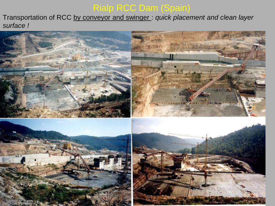
Rialp RCC Dam (Spain) Transportation of RCC by conveyor and swinger : quick placement and clean layer
surface !
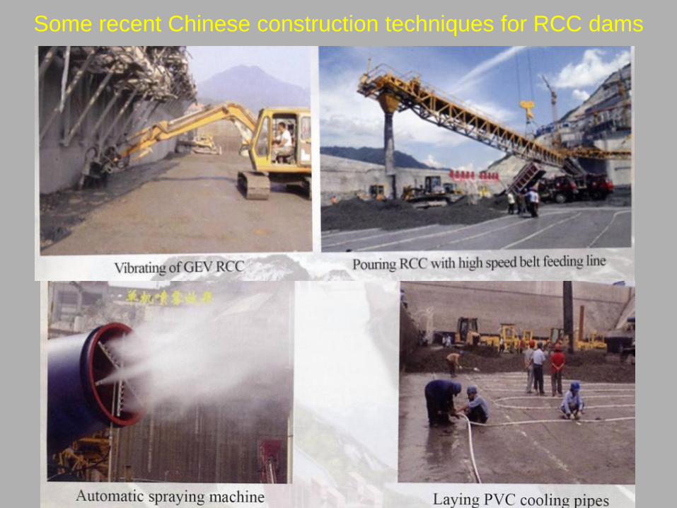
Some recent Chinese construction techniques for RCC dams

Sommaire
SummaryUse of Geomembrane
Balambano Dam (Indonesia)

Sommaire
Summary
For the Balambano dam the total
leakage through the dam is virtually
zero (some seepage appeared
through the foundation and the
abutments) : the geomembrane was
thus very efficient for the dam
watertightness.
Use of Geomembrane

Sommaire
SummaryOvertopping protection of
embankment dam by RCC : Brownwood Country Club Dam
(USA)
• Initially 6 m high earth dam
• First earth dam in USA to
receive RCC overtopping
protection (1984)
• Initial Flood = 74 m3/s
• Revised Flood (PMF)= 330
m3/s
• Overtopped 6 times since its
construction with no damage
• Volume of RCC = 1 070 m3
placed in 2 days
• 1/3 of the cost for increasing
spillway capacity by traditional
method
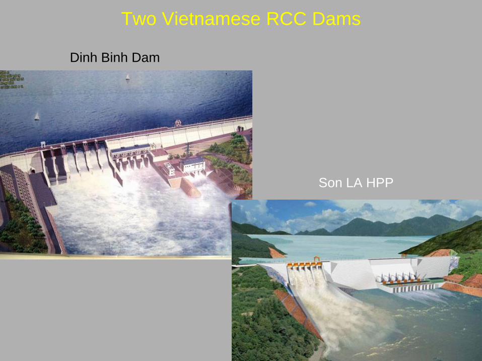
Two Vietnamese RCC Dams
Dinh Binh Dam
Son LA HPP

Dinh Binh Dam
Cementitious content of RCC (per m3)
Cat
Cement
(kg)
Fly Ash
(kg)
Sand
(kg)
A
.0.5x2
(kg)
A.2x4
(kg)
A.4x6
(kg)
Water
(l)
TM-20
(l)
P-96
(l)
RCC
15070 175 772 531 219 605 110 1.47 0.42
RCC
200126 141 746 852 468 0 132 1.6

Materials UnitsCement Flyash Total
kg/m3 VND kg/m3 VND VND
CONCRETE MIX
1x2, OK6-8M150, coarse
aggregate m3 296 251 600 488 095
M150, coarse aggregate
2x4, OK6-8m3 281 238 850 457 698
M150, coarse aggregate
4x6, OK6-8m3 266 226 100 426 709
RCC MIX
RCC MIX , M200 m3 126 110 754 141 97 572 440 953
RCC MIX, M150 m3 70 61 530 175 121 100 408 342
The RCC material costs (2007) are almost the same than the conventional concrete
material costs due to :
• the high percentage of cementitious materials,
• the similar treatment of aggregates.

Comments about the Dinh Binh RCC
The RCC cost of Dinh Binh dam (as other RCC dams in Vietnam) is
high compared with CVC. Why and how to lower it?
• Not optimal design: the design must optimize the cross-section of the dam, and
avoid as much as possible openings in the RCC. It is unecessary to design several
costly watertight barriers in the dam body. The most important is to select an adapted
RCC material, to optimize consequently the design and to have a good control during
the RCC placement.
• High fly ash cost: use fly ash only if there is a thermal powerplant near the site.
• Too high content of cementitious materials : avoid to normalize a minimum RCC
strength (for example RCC150 or RCC200), as for the CVC! Adjust this minimum value
according to the results of each optimization (materials/analysis) of the design.
The strengths of the RCC are too large compared to the required strengths. The
watertightness of the dam and its durability can be obtained by other cheaper
alternatives. The cost of the cementitious material must be lower than 30% of the total
cost of the RCC material, it is here almost equal to 50%!
• Low rate of construction: improve the organization of the works, adopt as much as
possible a continuous placement.
• Poor construction equipment: for dams with large volume (> 1 to 2 millions of m3),
select the RCC transportation by conveyor belt.
Is the RCC always the most economical alternative?
The advantages of the RCC technique are not conclusive for low and medium dams,
with large openings, built for flood control.

Son La Dam
Mix Proportions per m3 : Cement PCB 40 = 60 kg/ m3, Pulverized Fly Ash = 160 kg/ m3
Comment:
The required high tensile strength to resist to the design earthquake loadings is linked to the shape of the cross section of the dam.

Son La : The penstocks and the
powerhouse
• In this part of the dam, the RCC is
used only in the bottom and, not
easiliy, in the upper part, downstream
the intake.
• The placement of the RCC cannot
be continuous on the dam.
• The commissioning of the power
house cannot be done before the end
of construction of the dam.

Son La RCC sequence and rate of placementThe placement of the RCC is very discontinuous with peak near 10 000 m3/day (costly
construction equipment) and many weeks without placement .
Son La Hydropower Project
Daily RCC Production from 11 January 08 - 30 April 10
0
500
1000
1500
2000
2500
3000
3500
4000
4500
5000
5500
6000
6500
7000
7500
8000
8500
9000
9500
10000
10500
11-J
an-0
8
25-J
an-0
8
8-Fe
b-08
22-F
eb-0
8
7-M
ar-0
8
21-M
ar-0
8
4-A
pr-0
8
18-A
pr-0
8
2-M
ay-0
8
16-M
ay-0
8
30-M
ay-0
8
13-J
un-0
8
27-J
un-0
8
11-J
ul-0
8
25-J
ul-0
8
8-A
ug-0
8
22-A
ug-0
8
5-S
ep-0
8
19-S
ep-0
8
3-O
ct-0
8
17-O
ct-0
8
31-O
ct-0
8
14-N
ov-0
8
28-N
ov-0
8
12-D
ec-0
8
26-D
ec-0
8
9-Ja
n-09
23-J
an-0
9
6-Fe
b-09
20-F
eb-0
9
6-M
ar-0
9
20-M
ar-0
9
3-A
pr-0
9
17-A
pr-0
9
1-M
ay-0
9
15-M
ay-0
9
29-M
ay-0
9
12-J
un-0
9
26-J
un-0
9
10-J
ul-0
9
24-J
ul-0
9
7-A
ug-0
9
21-A
ug-0
9
4-S
ep-0
9
18-S
ep-0
9
2-O
ct-0
9
16-O
ct-0
9
30-O
ct-0
9
13-N
ov-0
9
27-N
ov-0
9
10-D
ec-0
9
24-D
ec-0
9
7-Ja
n-10
21-J
an-1
0
4-Fe
b-10
18-F
eb-1
0
4-M
ar-1
0
18-M
ar-1
0
1-A
pr-1
0
15-A
pr-1
0
29-A
pr-1
0
Date
Volu
me,
m3
0
1000
2000
3000
4000
5000
6000
7000
8000
9000
10000
11000
12000
13000
14000
15000
16000
17000
18000
19000
20000
21000
22000
23000
24000
25000
in H
undr
eds
Acc
u. V
olum
e, m
3
Total Volume of RCC Produced
Accumulated Volume
Maximum Daily
Production to Date
9918.75 m3

Sinking of the truck in the RCC
•Too much paste and water in the RCC.
Sufficient water content is required for
good bond between the layers but too
much water (bleeding and laitance) is
detrimental.
• Avoid as much as possible the use of
trucks on the RCC layers. Use as
possible conveyor belt and swinger.

Comparison Long Tan/Son La RCC Dams
Long Tan
• Volume of the dam : 6.6 hm3
• First concrete placement : November 2003
• End of concrete placement : November
2007
• Duration of dam construction : 48 months
(137 500 m3/month)
• Commission of the 3 first units : May 2007
• Delay between the concrete dam
placement and commission of the 3 first
units : 3.5 years
Son La
• Volume of the dam : 4.6 hm3
• First concrete placement : April 2007
• End of concrete placement : August
2010
• Duration of construction : 40 months
(115 000 m3/month)
• Commission of the first unit :
December 2010
• Delay between the concrete dam
dam placement and commission of
the first unit : 3 years

The Son La Design
1. The fly ash contents a high percentage of L.o.I and it is far from the site. It has to be
transported by trucks on roads frequently cut by landslides during the rainy season. It is
expensive and depends on an unique Vietnamese provider (Pha Lai powerplant).
2. The most economical alternative is to reduce as much as possible the quantity of fly ash. Is it
possible and how to do ?
– By giving a batter of 0.15 to 0.20 to the upstream face, instead of vertical, it will be
possible to reduce the maximal tensile strength (at maybe 0.3 to 0.5 MPa).
– With this last value of the tensile strength, the max required compressive strength of the
RCC can be reduced to 15 MPa.
– This value of RCC compressive strength (at 365 days) can probably be obtained with only
130 kg of cement* per m3 (and some 7% milled fines) without fly ash, or with 100 kg/ m3 of
cement and 50 kg/ m3 of flyash (total=150 kg/ m3 compared with 220 kg/ m3 used).
* This relative high percentage is due to a rather low grade cement (PCB 30 or 40), with then a relative
high cost for the transportation.
– The volume of the dam will be a little higher but, as the unit cost of the RCC is lower, the
total cost of the dam will certainly decrease.
- To improve the watertightness, the upstream face of the dam could be enriched in cement
and fly ash by the GEV-RCC method or by CVC. A light reinforcement mesh can be put, if
necessary.
- Even with 130 kg of cement per m3, the cooling of the RCC will not pose more problems
than the present situation, provided the vertical joints are correctly implemented.
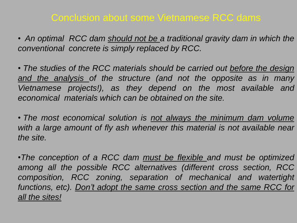
Conclusion about some Vietnamese RCC dams
• An optimal RCC dam should not be a traditional gravity dam in which the
conventional concrete is simply replaced by RCC.
• The studies of the RCC materials should be carried out before the design
and the analysis of the structure (and not the opposite as in many
Vietnamese projects!), as they depend on the most available and
economical materials which can be obtained on the site.
• The most economical solution is not always the minimum dam volume
with a large amount of fly ash whenever this material is not available near
the site.
•The conception of a RCC dam must be flexible and must be optimized
among all the possible RCC alternatives (different cross section, RCC
composition, RCC zoning, separation of mechanical and watertight
functions, etc). Don’t adopt the same cross section and the same RCC for
all the sites!

A particular type of RCC dam:
The Face Symmetrical Hardfill Dam (FSHD) and Cofferdam
• A new shape : fit with
incompetent or low
resistance foundation
• A cheap material : hardfill
– low cost aggregates
• natural alluviums
• mug from excavation
• soft rock
– low cement content Untreated natural alluviumsRio Grande dam in Peru

AVANTAGES OF
SYMMETRICAL
PROFILE
- low and uniform vertical
stress repartition
- little change in the vertical
stress with reservoir filling,
- no tension at the dam heel,
- uniform and reduced shear
stress at the base with the
seismic load
- small influence of uplift forces
improved stability
conditions in case of
earthquake and
large overtopping
10
0 m
C r itical r esultant
For ear thquake 0.2 g
A
1 2 C
D
2B
= 0.63
Empty
Full
0.8
= 24 kN / m 3
0 0.40 1.0Uplift
42°32°
10°
20°
30°
40°
27°
u d
(MPa)(MPa)
A = 0.84B = 1.56C = 2.40D = 0.00
PG
FSHD = 23 kN / m 3
0.7
0.7Critical resultantFor earthquake 0.2 g
u
(MPa) d
(MPa)
= 0.36
1
00
m
2
AC
2
DB
0 0.40 1.0
U plift
10°
20°
14°
22°
18°
Full
E m pt y A = 1.39B = 1.41
C = 1.15D = 1.15
1
1
11
11
Some examples of FSHD and FSH cofferdams:
- Cidere and Oyuk FSHD in Turkey
- Koudiat Acerdoune FSHD in Algeria
- Saf Saf FSHD and FSH cofferdam in Algeria
Sommaire
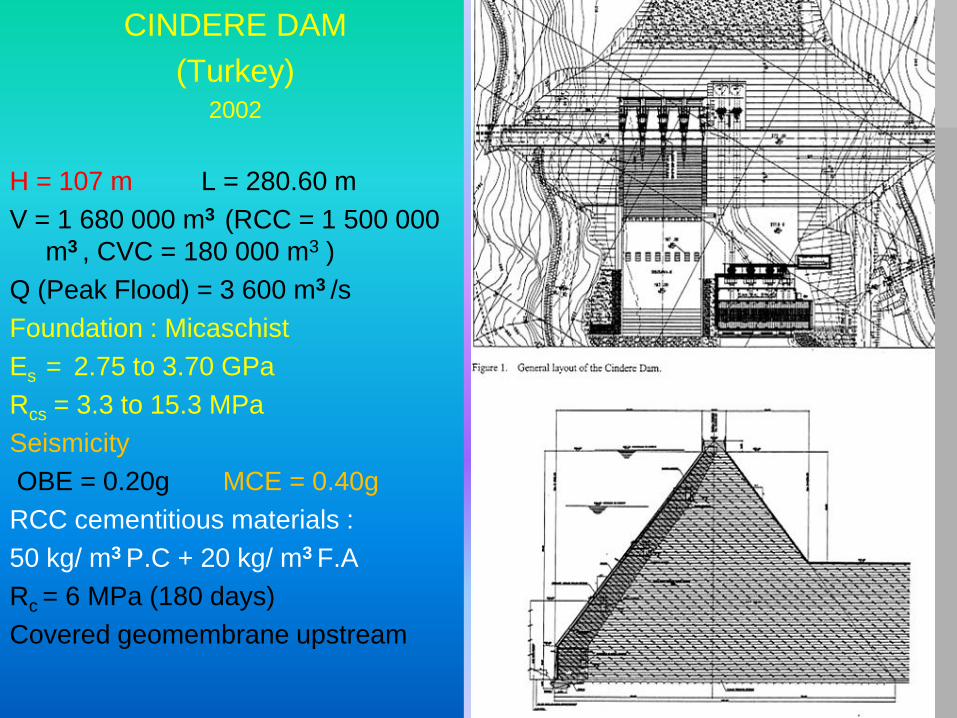
SummaryCINDERE DAM
(Turkey)2002
H = 107 m L = 280.60 m
V = 1 680 000 m3 (RCC = 1 500 000
m3 , CVC = 180 000 m3 )
Q (Peak Flood) = 3 600 m3 /s
Foundation : Micaschist
Es = 2.75 to 3.70 GPa
Rcs = 3.3 to 15.3 MPa
Seismicity
OBE = 0.20g MCE = 0.40g
RCC cementitious materials :
50 kg/ m3 P.C + 20 kg/ m3 F.A
Rc = 6 MPa (180 days)
Covered geomembrane upstream

OYUK Dam (Turkey)2007
H = 100 m L = 212 m
Q (Peak Flood 1/10 000) = 530 m3/s
Foundation : Gneiss and micaschist
Seismicity : OBE = 0.24g MCE = 0.40g
Cementitious materials : 50 kg/m3 P.C + 100 kg/m3 F.A
Rc = 6 MPa (90 days)

Koudiat Acerdoune (Algeria), H = 121 m, Crest Length = 493 m
A high RCC dam located in a seismic
area with low grade aggregates and with
very bad foundation (schist and marl)
with important rock slides during the
construction.
This dam was designed and constructed
by French consultants and contractors.

Choice of a FSHD cross-section to
adapt the design to the very low
quality of the foundation and of the
aggregates, with a reduction of Rc.
Replacement of the costly fly ash by
a limestone filler ground in situ.
Koudiat Acerdoun : Composition and characteristics of RCC
Initial design Final design
Quantity of RCC 1 070 000 m3 1 515 000 m3
Cement content 77 kg/m3 140 kg/m3
Fly Ash content 87 kg/m3 0
Limestone filler content 0 150 kg/m3
Required compressive strength 19 MPa at 90 days 11 MPa at 90 days
Max temperature 25°C 25°C

Diversion works for the Saf Saf FSHD (Algeria)
Low protection against flood during the construction
The Q10-yearflood = 890 m3/s, but the capacity of the diversion canal is only 150 m3/s (annual flood).
- In October 2008, a peak discharge flood of 500 m3/s overloaded
the canal capacity and the dam was overtopped with a 1.5 m
overflow depth, the base of the dam (3 m) was under construction.
- No damage resulted from this flood (no erosion of the crest, the
U/S and D/S faces of the dam). The works could start again after
a 2 weeks cleaning period.

Failure of the Cua Dat CFRD (Vietnam) during the construction
To minimize the cost of the diversion structures, it was admitted to divert the flow during the wet
season of 2007 by only one tunnel (D=9 m) in place of 2 tunnels (D= 11 m) of the initial design, with
a possible overtopping of the main dam 25 m higher than the river bed. Unfortunately an extreme
flood (8000 m3/s), much higher than expected (5300 m3/s), destroyed the gabion protection, the
cofferdam and a part of the dam during the construction (but without serious damage downstream).

Observation about FSHD for dam and cofferdam
1. A FSHD is particularly interesting for the sites with weak foundation, high floods
(often difficult to estimate precisely) and in seismic area. A FSHD can be
overflowed without serious damage during the construction permitting significant
savings in diversion works. FSHD may be consequently an interesting
alternative to CFRD for the sites with high floods and highly weathered rocks in
foundation. For this reason several FSHD are presently under construction in
Morocco in place of the traditional CFRD alternatives (Mr. Chraibi).
2. FSHD (or CSG) cofferdams - as demonstrated by their very good resistance to
large overflows - seem to be the best solution in case of overtopped structures,
even they may be a little more expensive than an embankment.
3. The failure of the Cua Dat CFRD must not lead to rule out the method of
diversion with overtopped structures - which allows generally important cost and
delay savings - but to adopt an adequate mode of protection of the downstream
slope of the embankment and, if necessary, of its toe and abutments. It is
probable that, if the downstream slope of this dam were protected by a
downstream FSHD in place of the gabions, the main dam and the RCC would
have resisted to the flood or be only superficially damaged.


