104
HTR-6230 AV Receiver OWNER’S MANUAL MANUAL DE INSTRUCCIONES R
HTR-6230AV Receiver
OWNER’S MANUALMANUAL DE INSTRUCCIONES
R
Caution-i En
1 To assure the finest performance, please read this manual carefully. Keep it in a safe place for future reference.
2 Install this sound system in a well ventilated, cool, dry, clean place – away from direct sunlight, heat sources, vibration, dust, moisture, and/or cold. Allow ventilation space of at least 30 cm on the top, 20 cm on the left and right, and 20 cm on the back of this unit.
3 Locate this unit away from other electrical appliances, motors, or transformers to avoid humming sounds.
4 Do not expose this unit to sudden temperature changes from cold to hot, and do not locate this unit in an environment with high humidity (i.e. a room with a humidifier) to prevent condensation inside this unit, which may cause an electrical shock, fire, damage to this unit, and/or personal injury.
5 Avoid installing this unit where foreign objects may fall onto this unit and/or this unit may be exposed to liquid dripping or splashing. On the top of this unit, do not place:– Other components, as they may cause damage and/or
discoloration on the surface of this unit.– Burning objects (i.e. candles), as they may cause fire,
damage to this unit, and/or personal injury.– Containers with liquid in them, as they may fall and liquid
may cause electrical shock to the user and/or damage to this unit.
6 Do not cover this unit with a newspaper, tablecloth, curtain, etc. in order not to obstruct heat radiation. If the temperature inside this unit rises, it may cause fire, damage to this unit, and/or personal injury.
7 Do not plug in this unit to a wall outlet until all connections are complete.
8 Do not operate this unit upside-down. It may overheat, possibly causing damage.
9 Do not use force on switches, knobs and/or cords.10 When disconnecting the power cable from the wall outlet,
grasp the plug; do not pull the cable.11 Do not clean this unit with chemical solvents; this might
damage the finish. Use a clean, dry cloth.12 Only voltage specified on this unit must be used. Using this
unit with a higher voltage than specified is dangerous and may cause fire, damage to this unit, and/or personal injury. Yamaha will not be held responsible for any damage resulting from use of this unit with a voltage other than specified.
13 To prevent damage by lightning, keep the power cord and outdoor antennas disconnected from a wall outlet or the unit during a lightning storm.
14 Do not attempt to modify or fix this unit. Contact qualified Yamaha service personnel when any service is needed. The cabinet should never be opened for any reasons.
15 When not planning to use this unit for long periods of time (i.e. vacation), disconnect the AC power plug from the wall outlet.
16 Install this unit near the AC outlet and where the AC power plug can be reached easily.
17 Be sure to read the “Troubleshooting” section on common operating errors before concluding that this unit is faulty.
18 Before moving this unit, press ASTANDBY/ON to set this unit in the standby mode, and disconnect the AC power plug from the wall outlet.
19 VOLTAGE SELECTOR (Asia and General models only)The VOLTAGE SELECTOR on the rear panel of this unit must be set for your local main voltage BEFORE plugging into the AC wall outlet. Voltages are:
........................................ AC 110–120/220–240 V, 50/60 Hz20 The batteries shall not be exposed to excessive heat such as
sunshine, fire or like.21 Excessive sound pressure from earphones and headphones can
cause hearing loss.22 When replacing the batteries, be sure to use batteries of the
same type. Danger of explosion may happen if batteries are incorrectly replaced.
Caution: Read this before operating your unit.
WARNINGTO REDUCE THE RISK OF FIRE OR ELECTRIC SHOCK, DO NOT EXPOSE THIS UNIT TO RAIN OR MOISTURE.
As long as this unit is connected to the AC wall outlet, it is not disconnected from the AC power source even if you turn off this unit by ASTANDBY/ON. In this state, this unit is designed to consume a very small quantity of power.
1 En
En
glish
INT
RO
DU
CT
ION
AD
DIT
ION
AL
IN
FO
RM
AT
ION
AP
PE
ND
IXP
RE
PAR
AT
ION
BA
SIC
O
PE
RA
TIO
NA
DVA
NC
ED
O
PE
RA
TIO
N
Features....................................................................2Supplied accessories .................................................. 2
Functional overview................................................3Front panel ................................................................. 3Front panel display..................................................... 4Remote control........................................................... 5Rear panel .................................................................. 6
Quick start guide.....................................................7L
Preparation of remote control ...............................8Connections .............................................................9
Placing speakers......................................................... 9Connecting speakers .................................................. 9Connecting video components................................. 11Connecting other components ................................. 13Using the VIDEO AUX jacks on the front panel .... 14Connecting the FM and AM antennas ..................... 15Connecting the power cable..................................... 15Turning on and off the power .................................. 15
Optimizing the speaker setting for your listening room (YPAO) ....................................................16Using AUTO SETUP............................................... 16
Playback.................................................................18Basic procedure........................................................ 18Additional operations............................................... 19
Selecting the SCENE templates ...........................22Selecting the desired SCENE template.................... 22Creating your original SCENE templates ................ 24Using remote control on the SCENE feature........... 25
Sound field programs ...........................................26Selecting sound field programs................................ 26
FM/AM tuning ......................................................28Overview.................................................................. 28FM/AM tuning operations ....................................... 28Preset FM/AM stations ............................................ 28
Set menu ................................................................ 30Using set menu......................................................... 311 SOUND MENU.................................................... 312 INPUT MENU...................................................... 333 OPTION MENU ................................................... 34
Remote control features ....................................... 36Controlling this unit, a TV, or other components .... 36Setting remote control codes.................................... 38
Advanced setup..................................................... 39
Troubleshooting.................................................... 40Glossary ................................................................. 45Specifications......................................................... 46Index ...................................................................... 47
(at the end of this manual)
Contents
INTRODUCTION
PREPARATION
BASIC OPERATION
ADVANCED OPERATION
ADDITIONAL INFORMATION
APPENDIX
List of remote control codes................................... i
About this manual• y indicates a tip for your operation.• Some operations can be performed by using either the buttons on the
front panel or the ones on the remote control. In case the button names differ between the front panel and the remote control, the button name on the remote control is given in parentheses.
• This manual is printed prior to production. Design and specifications are subject to change in part as a result of improvements, etc. In case of differences between the manual and product, the product has priority.
• “ASTANDBY/ON” or “fDVD” (example) indicates the name of the parts on the front panel or the remote control. Refer to the “Functional overview” on page 3.
INTRODUCTION
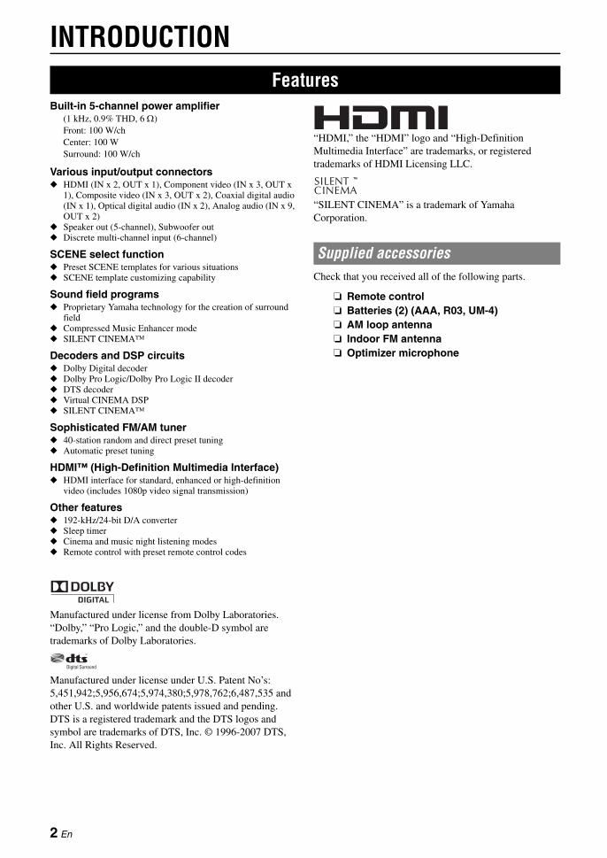
Built-in 5-channel power amplifier(1 kHz, 0.9% THD, 6 Ω)Front: 100 W/chCenter: 100 WSurround: 100 W/ch
Various input/output connectors◆ HDMI (IN x 2, OUT x 1), Component video (IN x 3, OUT x
1), Composite video (IN x 3, OUT x 2), Coaxial digital audio (IN x 1), Optical digital audio (IN x 2), Analog audio (IN x 9, OUT x 2)
◆ Speaker out (5-channel), Subwoofer out◆ Discrete multi-channel input (6-channel)
SCENE select function◆ Preset SCENE templates for various situations◆ SCENE template customizing capability
Sound field programs◆ Proprietary Yamaha technology for the creation of surround
field◆ Compressed Music Enhancer mode◆ SILENT CINEMA™
Decoders and DSP circuits◆ Dolby Digital decoder◆ Dolby Pro Logic/Dolby Pro Logic II decoder◆ DTS decoder◆ Virtual CINEMA DSP◆ SILENT CINEMA™
Sophisticated FM/AM tuner◆ 40-station random and direct preset tuning◆ Automatic preset tuning
HDMI™ (High-Definition Multimedia Interface)◆ HDMI interface for standard, enhanced or high-definition
video (includes 1080p video signal transmission)
Other features◆ 192-kHz/24-bit D/A converter◆ Sleep timer◆ Cinema and music night listening modes◆ Remote control with preset remote control codes
Manufactured under license from Dolby Laboratories.“Dolby,” “Pro Logic,” and the double-D symbol are trademarks of Dolby Laboratories.
Manufactured under license under U.S. Patent No’s:5,451,942;5,956,674;5,974,380;5,978,762;6,487,535 and other U.S. and worldwide patents issued and pending. DTS is a registered trademark and the DTS logos and symbol are trademarks of DTS, Inc. © 1996-2007 DTS, Inc. All Rights Reserved.
“HDMI,” the “HDMI” logo and “High-Definition Multimedia Interface” are trademarks, or registered trademarks of HDMI Licensing LLC.
“SILENT CINEMA” is a trademark of Yamaha Corporation.
Check that you received all of the following parts.
❏ Remote control❏ Batteries (2) (AAA, R03, UM-4)❏ AM loop antenna❏ Indoor FM antenna❏ Optimizer microphone
Features
Supplied accessories
2 En
En
glish
INT
RO
DU
CT
ION
AD
DIT
ION
AL
IN
FO
RM
AT
ION
AP
PE
ND
IXP
RE
PAR
AT
ION
BA
SIC
O
PE
RA
TIO
NA
DVA
NC
ED
O
PE
RA
TIO
N
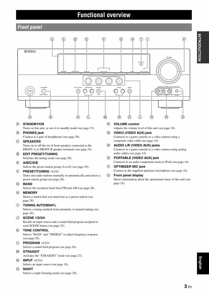
A STANDBY/ONTurns on this unit, or sets it to standby mode (see page 15).
B PHONES jackConnect to a pair of headphones (see page 20).
C SPEAKERSTurns on or off the set of front speakers connected to the FRONT A or FRONT B speaker terminals (see page 19).
D EDIT PRESET/TUNINGSwitches the tuning mode (see page 28).
E A/B/C/D/ESelects the preset station group (A to E) (see page 29).
F PRESET/TUNING l / h Tunes into radio stations manually or automatically and selects a preset station group (see page 28).
G BANDSelects the reception band from FM and AM (see page 28).
H MEMORYStores a station that you tuned into as a preset station (see page 28).
I TUNING AUTO/MAN’LSelects a tuning method from automatic or manual tuning (see page 28).
J SCENE 1/2/3/4Recalls an input source and a sound field program assigned to each SCENE button (see page 22).
K TONE CONTROLSelects “BASS” and “TREBLE” to adjust frequency response (see page 20).
L PROGRAM l / h Selects a sound field program (see page 26).
M STRAIGHTActivates the “STRAIGHT” mode (see page 27).
N INPUT l / h Selects an input source (see page 18).
O NIGHTSelects a night listening mode (see page 20).
P VOLUME controlAdjusts the volume level of this unit (see page 18).
Q VIDEO (VIDEO AUX) jackConnects to a game console or a video camera using a composite video cable (see page 14).
R AUDIO L/R (VIDEO AUX) jacksConnects to a game console or a video camera using analog audio cables (see page 14).
S PORTABLE (VIDEO AUX) jackConnects to an audio component (such as iPod) (see page 14).
T OPTIMIZER MIC jackConnect to the supplied optimizer microphone (see page 16).
U Front panel display Shows information about the operational status of this unit (see page 18).
Functional overview
Front panel
OPTIMIZER MIC
PHONES
SILENT CINEMA
TONE CONTROL PROGRAM STRAIGHT INPUT
VIDEO AUDIO PORTABLE
VIDEO AUX
VOLUME
EFFECT
l h l h
SCENE
STANDBY/ON
1
NIGHT
2 3 4
SPEAKERS PRESET/TUNINGEDIT
A/B/C/D/E PRESET/TUNINGl h BAND MEMORY TUNING AUTO/MAN'L
A
C D G H T
K OL N
IU PE F
J Q SB RM
3 En
Functional overview
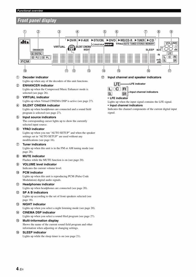
a Decoder indicatorLights up when any of the decoders of this unit functions.
b ENHANCER indicatorLights up when the Compressed Music Enhancer mode is selected (see page 26).
c VIRTUAL indicatorLights up when Virtual CINEMA DSP is active (see page 27).
d SILENT CINEMA indicatorLights up when headphones are connected and a sound field program is selected (see page 27).
e Input source indicators The corresponding cursor lights up to show the currently selected input source.
f YPAO indicatorLights up when you run “AUTO SETUP” and when the speaker settings set in “AUTO SETUP” are used without any modifications (see page 16).
g Tuner indicatorsLights up when this unit is in the FM or AM tuning mode (see page 28).
h MUTE indicatorFlashes while the MUTE function is on (see page 20).
i VOLUME level indicatorIndicates the current volume level.
j PCM indicatorLights up when this unit is reproducing PCM (Pulse Code Modulation) digital audio signals.
k Headphones indicatorLights up when headphones are connected (see page 20).
l SP A B indicatorsLights up according to the set of front speakers selected (see page 18).
m NIGHT indicatorLights up when you select a night listening mode (see page 20).
n CINEMA DSP indicatorLights up when you select a sound filed program (see page 27).
o Multi-information displayShows the name of the current sound field program and other information when adjusting or changing settings.
p SLEEP indicatorLights up while the sleep timer is on (see page 21).
q Input channel and speaker indicators
• LFE indicatorLights up when the input signal contains the LFE signal.• Input channel indicatorsIndicates the channel components of the current digital input signal.
Front panel display
DVR DVD CDV-AUX DTV/CBL MD/CD-R TUNER
ENHANCERSILENT CINEMA
NIGHT
AUTOYPAOPRESET
TUNED
MUTE
VOLUMEMEMORY
SLEEPVIRTUAL
PCM
A BSP
mS
ft
dB
LFEL C RSL SR
dB
STEREO
q PLq PLq DIGITAL
t
a b c d fe g h i
j k l m n o p q
LFEL C RSL SR
LFE indicator
Input channel indicators
4 En
Functional overviewE
ng
lishIN
TR
OD
UC
TIO
NA
DD
ITIO
NA
L
INF
OR
MA
TIO
NA
PP
EN
DIX
PR
EPA
RA
TIO
NB
AS
IC
OP
ER
AT
ION
AD
VAN
CE
D
OP
ER
AT
ION
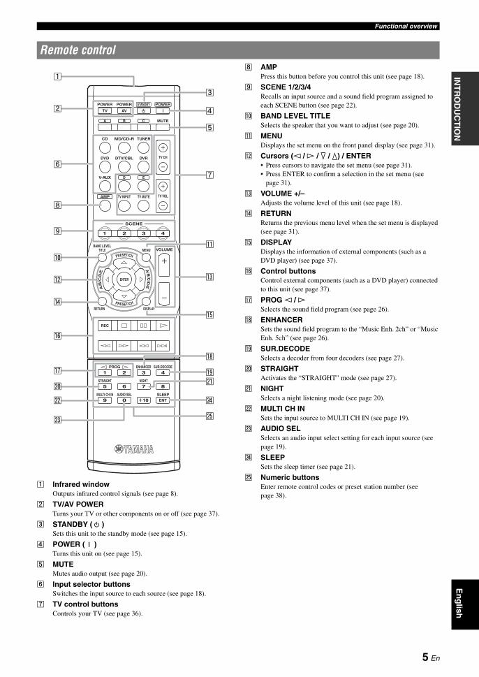
a Infrared windowOutputs infrared control signals (see page 8).
b TV/AV POWER Turns your TV or other components on or off (see page 37).
c STANDBY ( ) Sets this unit to the standby mode (see page 15).
d POWER ( ) Turns this unit on (see page 15).
e MUTE Mutes audio output (see page 20).
f Input selector buttonsSwitches the input source to each source (see page 18).
g TV control buttons Controls your TV (see page 36).
h AMP Press this button before you control this unit (see page 18).
i SCENE 1/2/3/4Recalls an input source and a sound field program assigned to each SCENE button (see page 22).
j BAND LEVEL TITLESelects the speaker that you want to adjust (see page 20).
k MENUDisplays the set menu on the front panel display (see page 31).
l Cursors (l / h / n / k) / ENTER• Press cursors to navigate the set menu (see page 31).• Press ENTER to confirm a selection in the set menu (see
page 31).
m VOLUME +/–Adjusts the volume level of this unit (see page 18).
n RETURN Returns the previous menu level when the set menu is displayed (see page 31).
o DISPLAY Displays the information of external components (such as a DVD player) (see page 37).
p Control buttonsControl external components (such as a DVD player) connected to this unit (see page 37).
q PROG l / h Selects the sound field program (see page 26).
r ENHANCER Sets the sound field program to the “Music Enh. 2ch” or “Music Enh. 5ch” (see page 26).
s SUR.DECODE Selects a decoder from four decoders (see page 27).
t STRAIGHT Activates the “STRAIGHT” mode (see page 27).
u NIGHT Selects a night listening mode (see page 20).
v MULTI CH IN Sets the input source to MULTI CH IN (see page 19).
w AUDIO SELSelects an audio input select setting for each input source (see page 19).
x SLEEPSets the sleep timer (see page 21).
y Numeric buttonsEnter remote control codes or preset station number (see page 38).
Remote control
POWER
CD MD/CD-R TUNER
DVD
V-AUX
BAND LEVELTITLE MENU
RETURN
ENTER
REC
PROG ENHANCER SUR.DECODE
STRAIGHT NIGHT
MULTI CH IN AUDIO SEL SLEEPENT
DISPLAY
VOLUME
AMP
DTV/CBL DVR TV CH
TV VOLTV INPUT TV MUTE
POWER POWER
MUTE
STANDBY
TV
A B
AV
C
D E
SCENE
1 2
2 3 41
6
0
7
10
85
9
3 4
PRESET/CH
A/B
/C/D
/E
PRESET/CH
A/B
/C/D
/E
y
c
k
r
u
o
d
e
s
x
g
m
a
b
i
q
p
h
j
n
t
v
f
l
w
5 En

Functional overview
a COMPONENT VIDEO jacksConnect to Y, PB/CB and PR/CR jacks on your video components with component video cables (see page 11).• DVD input jacks• DTV/CBL input jacks• DVR input jacks• MONITOR OUT output jacks
b HDMI terminalsConnect to HDMI output/input terminals on your external components with HDMI cables (see page 11).• HDMI DVD terminal• HDMI DTV/CBL terminal• HDMI OUT output terminal
c VIDEO jacksConnect to video jacks on your video components with composite video cables (see page 11).• DVD input jack• DTV/CBL input jack• DVR IN jack• DVR OUT jack• MONITOR OUT jack
d ANTENNA terminalsConnect to the supplied FM and AM antennas (see page 15).
e SPEAKERS terminalsConnect to each speakers (see page 9).• FRONT A L/R• FRONT B L/R• SURROUND L/R• CENTER
f DIGITAL INPUT jacksConnect to the DIGITAL output jacks on your digital audio components with Coaxial/Optical digital audio cables. This input jacks support PCM, Dolby Digital and DTS bitstream (see page 11).• COAXIAL (DVD)• OPTICAL (DTV/CBL)• OPTICAL (CD)
g MULTI CH INPUT jacksConnect to the output jacks on your multi-format player or external decoder with analog audio cables (see page 14).• FRONT L/R jack• SURROUND L/R jack• CENTER jack• SUBWOOFER jack
h AUDIO jacksConnect to the audio output/input jacks on your components with analog audio cables (see page 11).• DVD L/R jack• DTV/CBL L/R jack• DVR IN L/R jack• DVR OUT L/R jack• CD L/R jack• IN (PLAY) L/R jack • OUT (REC) L/R jack
i SUBWOOFER OUTPUT jackConnect to a Subwoofer with an analog audio cable (see page 9).
j VOLTAGE SELECTORSelect the switch position according to your local voltage (see page 15).
k Power cableConnect to a standard AC outlet (see page 15).
Rear panel
DIGITAL INPUT
COMPONENT VIDEO
VIDEO
AUDIOMULTI CH INPUT
HDMI
ANTENNA SPEAKERS
DVD
OPTICAL
DVDSURROUND CENTER FRONT B
FRONT A
DVR
SURROUNDFRONT CENTER
SUBWOOFER
DTV/CBL
DVD DVR FM
AM
GND
IN OUTDTV/CBL
DVD DVR CDOUTPUT
SUBWOOFR
IN OUTMD/
CD-RIN
(PLAY)OUT
(REC)DTV/CBL
DTV/CBL
MONITOROUT
MONITOROUT
CD
PR
PB
Y
DVD
COAXIAL
DTV/CBL
OUT
UNBAL.
f g h i
d eb ca
j k
6 En
En
glish
INT
RO
DU
CT
ION
AD
DIT
ION
AL
IN
FO
RM
AT
ION
AP
PE
ND
IXP
RE
PAR
AT
ION
BA
SIC
O
PE
RA
TIO
NA
DVA
NC
ED
O
PE
RA
TIO
N
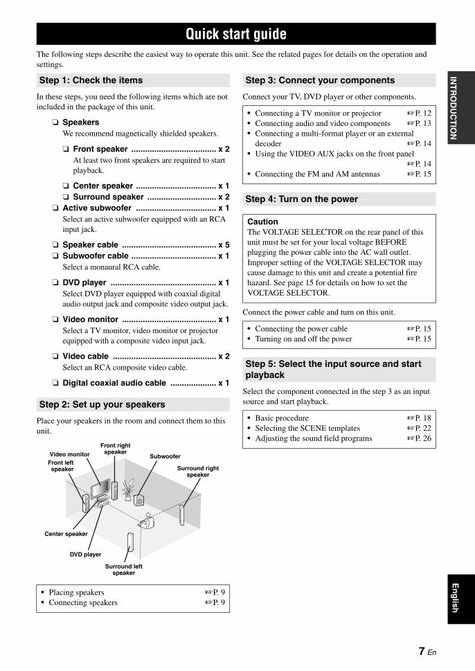
The following steps describe the easiest way to operate this unit. See the related pages for details on the operation and settings.
In these steps, you need the following items which are not included in the package of this unit.
❏ SpeakersWe recommend magnetically shielded speakers.
❏ Front speaker ..................................... x 2At least two front speakers are required to start playback.
❏ Center speaker ................................... x 1❏ Surround speaker .............................. x 2
❏ Active subwoofer ................................... x 1Select an active subwoofer equipped with an RCA input jack.
❏ Speaker cable ......................................... x 5❏ Subwoofer cable ..................................... x 1
Select a monaural RCA cable.
❏ DVD player .............................................. x 1Select DVD player equipped with coaxial digital audio output jack and composite video output jack.
❏ Video monitor ......................................... x 1Select a TV monitor, video monitor or projector equipped with a composite video input jack.
❏ Video cable ............................................. x 2Select an RCA composite video cable.
❏ Digital coaxial audio cable .................... x 1
Place your speakers in the room and connect them to this unit.
Connect your TV, DVD player or other components.
Connect the power cable and turn on this unit.
Select the component connected in the step 3 as an input source and start playback.
Quick start guide
Step 1: Check the items
Step 2: Set up your speakers
• Placing speakers ☞P. 9• Connecting speakers ☞P. 9
Video monitorFront leftspeaker
Center speaker
DVD player
Surround left speaker
Surround right speaker
Subwoofer
Front right speaker
Step 3: Connect your components
• Connecting a TV monitor or projector ☞P. 12• Connecting audio and video components ☞P. 13• Connecting a multi-format player or an external
decoder ☞P. 14• Using the VIDEO AUX jacks on the front panel
☞P. 14• Connecting the FM and AM antennas ☞P. 15
Step 4: Turn on the power
CautionThe VOLTAGE SELECTOR on the rear panel of this unit must be set for your local voltage BEFORE plugging the power cable into the AC wall outlet. Improper setting of the VOLTAGE SELECTOR may cause damage to this unit and create a potential fire hazard. See page 15 for details on how to set the VOLTAGE SELECTOR.
• Connecting the power cable ☞P. 15• Turning on and off the power ☞P. 15
Step 5: Select the input source and start playback
• Basic procedure ☞P. 18• Selecting the SCENE templates ☞P. 22• Adjusting the sound field programs ☞P. 26
7 En

PREPARATION
1 Take off the battery compartment cover.
2 Insert the four supplied batteries (AAA, R03, UM-4) according to the polarity markings (+ and –) on the inside of the battery compartment.
3 Snap the battery compartment cover back into place.
Notes• Change all of the batteries if you notice the following conditions:
– the operation range of the remote control decreases.• Do not use old batteries together with new ones.• Do not use different types of batteries (such as alkaline and
manganese batteries) together. Read the packaging carefully as these different types of batteries may have the same shape and color.
• If the batteries have leaked, dispose of them immediately. Avoid touching the leaked material or letting it come into contact with clothing, etc. Clean the battery compartment thoroughly before installing new batteries.
• Do not throw away batteries with general house waste; dispose of them correctly in accordance with your local regulations.
• If the remote control is without batteries for more than 2 minutes, or if exhausted batteries remain in the remote control, the contents of the memory may be cleared. When the memory is cleared, insert new batteries and set up the remote control code.
The remote control transmits a directional infrared ray.Be sure to aim the remote control directly at the remote control sensor on this unit during operation.
a Infrared windowOutputs infrared control signals. Aim this window at the component you want to operate.
y• To set the remote control codes for other components, see page 38.
Notes• Do not spill water or other liquids on the remote control.• Do not drop the remote control.• Do not leave or store the remote control in the following types of
conditions:– places of high humidity, such as near a bath– places of high temperature, such as near a heater or stove– places of extremely low temperatures– dusty places
• To set the remote control codes for other components, see page 38.
Preparation of remote control
Installing batteries in the remote control
1 3
2
Using the remote control
30º 30º Approximately 6 m (20 ft)
8 En
En
glish
INT
RO
DU
CT
ION
AD
DIT
ION
AL
IN
FO
RM
AT
ION
AP
PE
ND
IXP
RE
PAR
AT
ION
BA
SIC
O
PE
RA
TIO
NA
DVA
NC
ED
O
PE
RA
TIO
N
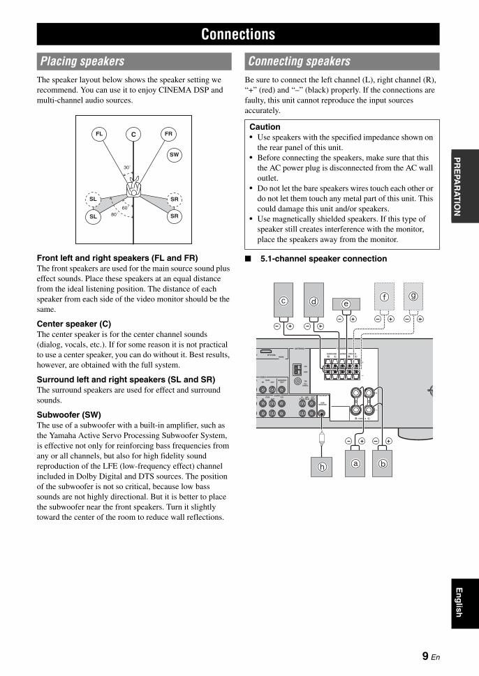
The speaker layout below shows the speaker setting we recommend. You can use it to enjoy CINEMA DSP and multi-channel audio sources.
Front left and right speakers (FL and FR)The front speakers are used for the main source sound plus effect sounds. Place these speakers at an equal distance from the ideal listening position. The distance of each speaker from each side of the video monitor should be the same.
Center speaker (C)The center speaker is for the center channel sounds (dialog, vocals, etc.). If for some reason it is not practical to use a center speaker, you can do without it. Best results, however, are obtained with the full system.
Surround left and right speakers (SL and SR)The surround speakers are used for effect and surround sounds.
Subwoofer (SW)The use of a subwoofer with a built-in amplifier, such as the Yamaha Active Servo Processing Subwoofer System, is effective not only for reinforcing bass frequencies from any or all channels, but also for high fidelity sound reproduction of the LFE (low-frequency effect) channel included in Dolby Digital and DTS sources. The position of the subwoofer is not so critical, because low bass sounds are not highly directional. But it is better to place the subwoofer near the front speakers. Turn it slightly toward the center of the room to reduce wall reflections.
Be sure to connect the left channel (L), right channel (R), “+” (red) and “–” (black) properly. If the connections are faulty, this unit cannot reproduce the input sources accurately.
■ 5.1-channel speaker connection
Connections
Placing speakers
60˚
30˚
FL FRC
SL
SR
SR80˚
SL
SW
Connecting speakers
Caution• Use speakers with the specified impedance shown on
the rear panel of this unit.• Before connecting the speakers, make sure that this
the AC power plug is disconnected from the AC wall outlet.
• Do not let the bare speakers wires touch each other or do not let them touch any metal part of this unit. This could damage this unit and/or speakers.
• Use magnetically shielded speakers. If this type of speaker still creates interference with the monitor, place the speakers away from the monitor.
LRLR
LR
HDMI
VIDEO
AUDIO OUTPUT
ANTENNA SPEAKERS
BL
D DTV/CBLSURROUND CENTER FRONT B
FRONT A
MONITOR OUT
MD/ CD-R
SUB WOOFER
OUT (REC)
IN (PLAY)
DVR
BL DVR CD
IN OUT
IN OUT
AM
GND
FM
75 UNBAL.
a b
c df g
e
h
9 En
Connections
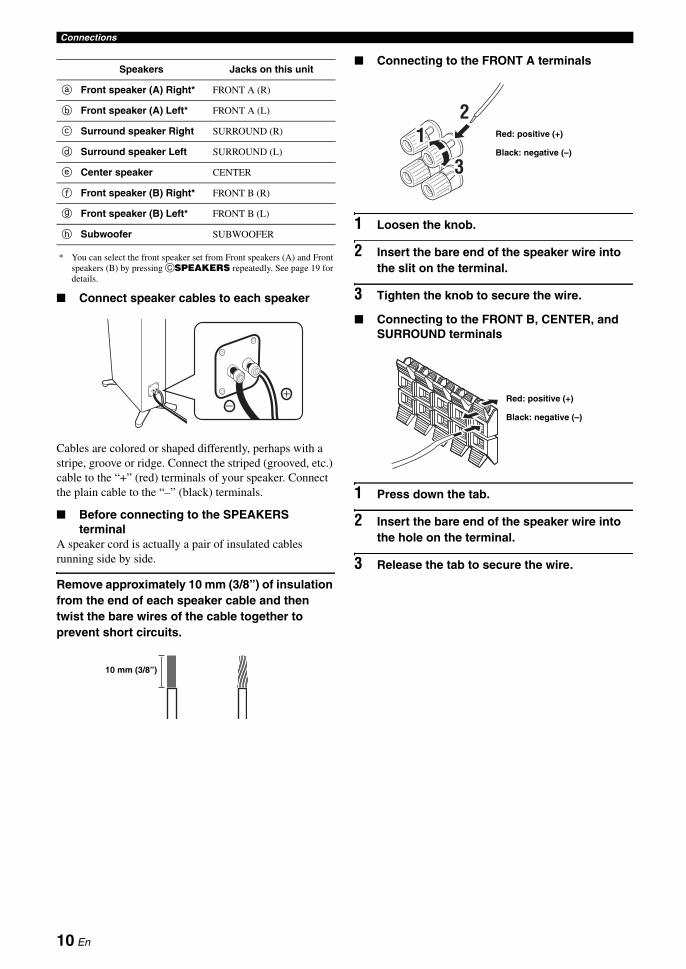
* You can select the front speaker set from Front speakers (A) and Front speakers (B) by pressing CSPEAKERS repeatedly. See page 19 for details.
■ Connect speaker cables to each speaker
Cables are colored or shaped differently, perhaps with a stripe, groove or ridge. Connect the striped (grooved, etc.) cable to the “+” (red) terminals of your speaker. Connect the plain cable to the “–” (black) terminals.
■ Before connecting to the SPEAKERS terminal
A speaker cord is actually a pair of insulated cables running side by side.
Remove approximately 10 mm (3/8”) of insulation from the end of each speaker cable and then twist the bare wires of the cable together to prevent short circuits.
■ Connecting to the FRONT A terminals
1 Loosen the knob.
2 Insert the bare end of the speaker wire into the slit on the terminal.
3 Tighten the knob to secure the wire.
■ Connecting to the FRONT B, CENTER, and SURROUND terminals
1 Press down the tab.
2 Insert the bare end of the speaker wire into the hole on the terminal.
3 Release the tab to secure the wire.
Speakers Jacks on this unit
a Front speaker (A) Right* FRONT A (R)
b Front speaker (A) Left* FRONT A (L)
c Surround speaker Right SURROUND (R)
d Surround speaker Left SURROUND (L)
e Center speaker CENTER
f Front speaker (B) Right* FRONT B (R)
g Front speaker (B) Left* FRONT B (L)
h Subwoofer SUBWOOFER
10 mm (3/8”)
12
3
Red: positive (+)
Black: negative (–)
Red: positive (+)
Black: negative (–)
10 En
ConnectionsE
ng
lishIN
TR
OD
UC
TIO
NA
DD
ITIO
NA
L
INF
OR
MA
TIO
NA
PP
EN
DIX
PR
EPA
RA
TIO
NB
AS
IC
OP
ER
AT
ION
AD
VAN
CE
D
OP
ER
AT
ION
Audio jacks and cable plugs
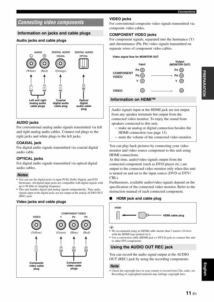
AUDIO jacksFor conventional analog audio signals transmitted via left and right analog audio cables. Connect red plugs to the right jacks and white plugs to the left jacks.
COAXIAL jackFor digital audio signals transmitted via coaxial digital audio cable.
OPTICAL jacksFor digital audio signals transmitted via optical digital audio cables.
Notes• You can use the digital jacks to input PCM, Dolby Digital, and DTS
bitstreams. All digital input jacks are compatible with digital signals with up to 96 kHz of sampling frequency.
• This unit handles digital and analog signals independently. Thus audio signals input at the digital jacks are not output at the analog AUDIO OUT (REC) jack.
Video jacks and cable plugs
VIDEO jacksFor conventional composite video signals transmitted via composite video cables.
COMPONENT VIDEO jacksFor component signals, separated into the luminance (Y) and chrominance (PB, PR) video signals transmitted on separate wires of component video cables.
You can play back pictures by connecting your video monitor and video source component to this unit using HDMI connections.At that time, audio/video signals output from the connected component (such as DVD player etc.) are output to the connected video monitor only when this unit is turned on and set to the input source (DVD or DTV/CBL).Furthermore, available audio/video signals depend on the specification of the connected video monitor. Refer to the instruction manual of each connected component.
■ HDMI jack and cable plug
y• We recommend using an HDMI cable shorter than 5 meters (16 feet)
with the HDMI logo printed on it.• Use a conversion cable (HDMI jack ↔ DVI-D jack) to connect this unit
to other DVI components.
You can record the audio signal output at the AUDIO OUT (REC) jack by using the recording components.
Note• Check the copyright laws in your country to record from CDs, radio, etc.
Recording of copyrighted material may infringe copyright laws.
Connecting video components
Information on jacks and cable plugs
COAXIAL
DIGITAL AUDIOAUDIO
OPTICAL
DIGITAL AUDIORL
CORL
(White) (Red) (Orange)
Left and right analog audio cable plugs
Coaxial digital audio cable plug
Optical digital
audio cable plug
VIDEOCOMPONENT VIDEO
Y PB PR
PBY PRV
(Yellow) (Blue) (Red)(Green)
Composite video cable
plug
Component video cable
plugs
Information on HDMI™
Audio signals input at the HDMI jack are not output from any speaker terminals but output from the connected video monitor. To enjoy the sound from speakers connected to this unit,
– make an analog or digital connection besides the HDMI connection (see page 13).
– mute the volume of the connected video monitor.
Using the AUDIO OUT REC jack
PR
PB
Y
PR
PB
Y
COMPONENTVIDEO
VIDEO
Video signal flow for MONITOR OUT
InputOutput
(MONITOR OUT)
HDMI
HDMI cable plug
11 En
Connections
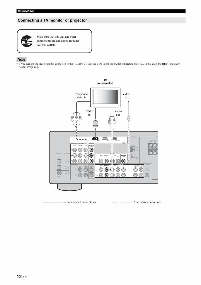
Note• If you turn off the video monitor connected to the HDMI OUT jack via a DVI connection, the connection may fail. In this case, the HDMI indicator
flashes irregularly.
Connecting a TV monitor or projector
Make sure that this unit and other
components are unplugged from the
AC wall outlets.
LR
L
R
VIDEO
MULTI CH INPUT
DIGITAL INPUT
OUTPUT
ANTENNA SPE
1
2
3
DVD
DVD
COAXIAL
OPTICAL
CD
DTV/CBL
DTV/ CBL
SURROUND CE
MONITOR OUT
SUB WOOFER
DVR
FRONT CENTER
SUBWOOFER
SURROUND
IN OUT
AM
GND
FM
75 UNBAL.
HDMI
DVDOUT DTV/CBL
COMPONENT VIDEODVD DTV/CBL DVR MONITOR
OUT
Y
PR
PB
VPRPBY
LR
MD/ CD-R
OUT (REC)
IN (PLAY)
L
R
AUDIODVD DTV/CBL DVR CD
IN OUT
TV (or projector)
Component video in
Video in
Audio out
HDMI in
Recommended connections Alternative connections
12 En

ConnectionsE
ng
lishIN
TR
OD
UC
TIO
NA
DD
ITIO
NA
L
INF
OR
MA
TIO
NA
PP
EN
DIX
PR
EPA
RA
TIO
NB
AS
IC
OP
ER
AT
ION
AD
VAN
CE
D
OP
ER
AT
ION
This unit has three types of audio jacks, two types of video jacks and HDMI jacks. You can choose the connection method depending on the component to be connected.
■ Connecting example (connecting a DVD player)
■ Jacks used for audio and video connectionsRecommended connections are indicated by (*). When connecting a recording component, you need to make additional connections for recording (signal transmission from this unit to the recording component).
y• You can also use the VIDEO AUX jacks (see page 14) on the front panel
to connect an additional component.• To confirm the positions of “jacks on this unit” in the following table,
refer to “Rear panel” in “Functional overview” on page 6.
Connecting other components
Connecting audio and video components
R
L
R
L
R
COMPONENT VIDEO
HDMI
VIDEO
AUDIOMULTI CH INPUT
DIGITAL INPUT
OUTPUT
ANTENNA
1
2
3
DVD DTV/CBL DVR
DVD
DVD
COAXIAL
OPTICAL
CD
DTV/CBL
DTV/ CBL
DVDOUT DTV/CBLSU
MONITOR OUT
MD/ CD-R
SUB WOOFER
OUT (REC)
IN (PLAY)
DVR
DVDFRONT CENTER
SUBWOOFER
SURROUNDDTV/CBL DVR CD
IN OUT
IN OUT
MONITOR OUT
AM
GND
FM
75 UNBAL.
Y
PR
PB
PRPBYL R
C
V
Com
ponent out
Audio out
Video out
Coaxial outHDMI out
Recommended connections Alternative connections
Make sure that this unit and other
components are unplugged from the
AC wall outlets.
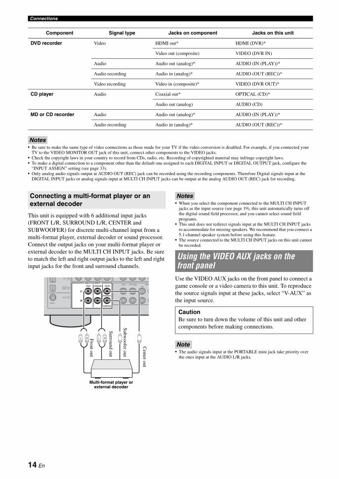
Component Signal type Jacks on component Jacks on this unit
DVD player or Blu-ray Disc player
Video HDMI out* HDMI (DVD)*
Component out COMPONENT VIDEO (DVD)
Video out (composite) VIDEO (DVD)
Audio Optical out* COAXIAL (DVD)*
Audio out (analog) AUDIO (DVD)
Set-top box Video HDMI out* HDMI (DTV/CBL)*
Component out COMPONENT VIDEO (DTV/CBL)
Video out (composite) VIDEO (DTV/CBL)
Audio Optical out* OPTICAL (DTV/CBL)*
Analog out (analog) AUDIO (DTV/CBL)
13 En
Connections
Notes• Be sure to make the same type of video connections as those made for your TV if the video conversion is disabled. For example, if you connected your
TV to the VIDEO MONITOR OUT jack of this unit, connect other components to the VIDEO jacks.• Check the copyright laws in your country to record from CDs, radio, etc. Recording of copyrighted material may infringe copyright laws.• To make a digital connection to a component other than the default one assigned to each DIGITAL INPUT or DIGITAL OUTPUT jack, configure the
“INPUT ASSIGN” setting (see page 33).• Only analog audio signals output at AUDIO OUT (REC) jack can be recorded using the recording components. Therefore Digital signals input at the
DIGITAL INPUT jacks or analog signals input at MULTI CH INPUT jacks can be output at the analog AUDIO OUT (REC) jack for recording.
This unit is equipped with 6 additional input jacks (FRONT L/R, SURROUND L/R, CENTER and SUBWOOFER) for discrete multi-channel input from a multi-format player, external decoder or sound processor. Connect the output jacks on your multi-format player or external decoder to the MULTI CH INPUT jacks. Be sure to match the left and right output jacks to the left and right input jacks for the front and surround channels.
Notes• When you select the component connected to the MULTI CH INPUT
jacks as the input source (see page 19), this unit automatically turns off the digital sound field processor, and you cannot select sound field programs.
• This unit does not redirect signals input at the MULTI CH INPUT jacks to accommodate for missing speakers. We recommend that you connect a 5.1-channel speaker system before using this feature.
• The source connected to the MULTI CH INPUT jacks on this unit cannot be recorded.
Use the VIDEO AUX jacks on the front panel to connect a game console or a video camera to this unit. To reproduce the source signals input at these jacks, select “V-AUX” as the input source.
Note• The audio signals input at the PORTABLE mini jack take priority over
the ones input at the AUDIO L/R jacks.
DVD recorder Video HDMI out* HDMI (DVR)*
Video out (composite) VIDEO (DVR IN)
Audio Audio out (analog)* AUDIO (IN (PLAY))*
Audio recording Audio in (analog)* AUDIO (OUT (REC))*
Video recording Video in (composite)* VIDEO (DVR OUT)*
CD player Audio Coaxial out* OPTICAL (CD)*
Audio out (analog) AUDIO (CD)
MD or CD recorder Audio Audio out (analog)* AUDIO (IN (PLAY))*
Audio recording Audio in (analog)* AUDIO (OUT (REC))*
Component Signal type Jacks on component Jacks on this unit
Connecting a multi-format player or an external decoder
L
R
L
R
MULTI CH INPUT
1
2
3
DVD
COAXIAL
CD
DTV/ CBL
DVDFRONT CENTER
SUBWOOFER
SURROUNDDTV/CBL DVR
IN
L R L RFront out
Surround out
Subw
oofer out
Center out
Multi-format player or external decoder
Using the VIDEO AUX jacks on the front panel
CautionBe sure to turn down the volume of this unit and other components before making connections.
14 En
ConnectionsE
ng
lishIN
TR
OD
UC
TIO
NA
DD
ITIO
NA
L
INF
OR
MA
TIO
NA
PP
EN
DIX
PR
EPA
RA
TIO
NB
AS
IC
OP
ER
AT
ION
AD
VAN
CE
D
OP
ER
AT
ION
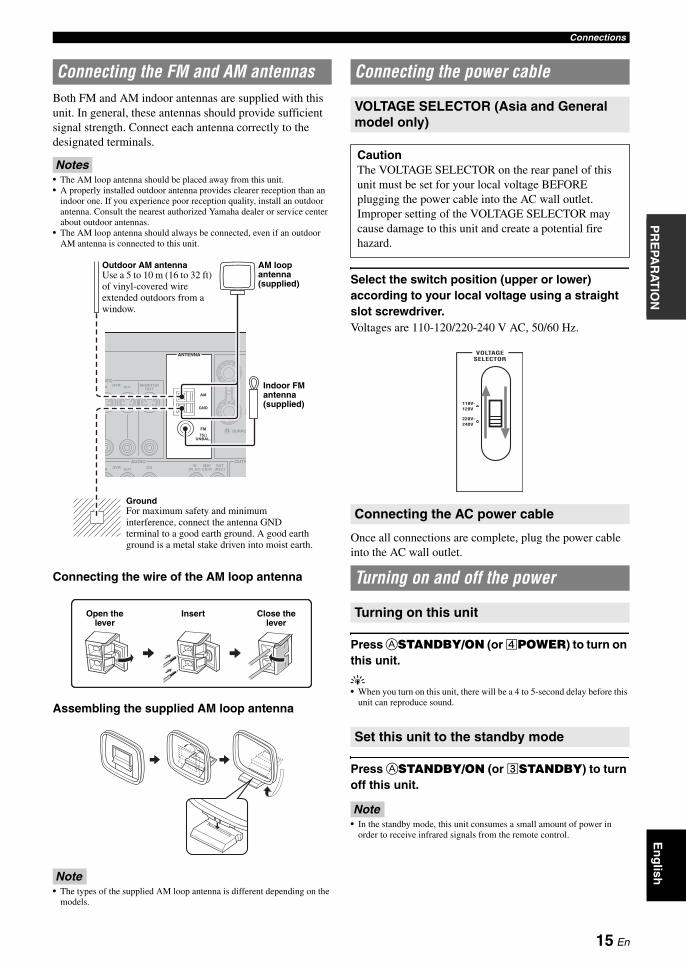
Both FM and AM indoor antennas are supplied with this unit. In general, these antennas should provide sufficient signal strength. Connect each antenna correctly to the designated terminals.
Notes• The AM loop antenna should be placed away from this unit.• A properly installed outdoor antenna provides clearer reception than an
indoor one. If you experience poor reception quality, install an outdoor antenna. Consult the nearest authorized Yamaha dealer or service center about outdoor antennas.
• The AM loop antenna should always be connected, even if an outdoor AM antenna is connected to this unit.
Connecting the wire of the AM loop antenna
Assembling the supplied AM loop antenna
Note• The types of the supplied AM loop antenna is different depending on the
models.
Select the switch position (upper or lower) according to your local voltage using a straight slot screwdriver.Voltages are 110-120/220-240 V AC, 50/60 Hz.
Once all connections are complete, plug the power cable into the AC wall outlet.
Press ASTANDBY/ON (or dPOWER) to turn on this unit.
y• When you turn on this unit, there will be a 4 to 5-second delay before this
unit can reproduce sound.
Press ASTANDBY/ON (or cSTANDBY) to turn off this unit.
Note• In the standby mode, this unit consumes a small amount of power in
order to receive infrared signals from the remote control.
Connecting the FM and AM antennas
DEO
ANTENNA
R SURRO
AUDIO OUTPDVR CD
S
N OUT
DVR
AM
GND
FM
UNBAL.75
N OUT MONITOR OUT
MD/CD-R
OUT (REC)
IN (PLAY)
Outdoor AM antennaUse a 5 to 10 m (16 to 32 ft) of vinyl-covered wire extended outdoors from a window.
AM loop antenna (supplied)
Indoor FM antenna (supplied)
GroundFor maximum safety and minimum interference, connect the antenna GND terminal to a good earth ground. A good earth ground is a metal stake driven into moist earth.
Open the lever
Insert Close the lever
Connecting the power cable
VOLTAGE SELECTOR (Asia and General model only)
CautionThe VOLTAGE SELECTOR on the rear panel of this unit must be set for your local voltage BEFORE plugging the power cable into the AC wall outlet.Improper setting of the VOLTAGE SELECTOR may cause damage to this unit and create a potential fire hazard.
Connecting the AC power cable
Turning on and off the power
Turning on this unit
Set this unit to the standby mode
110V- 120V
220V- 240V
VOLTAGESELECTOR
15 En
This unit has the Yamaha Parametric Acoustic Optimizer (YPAO). With the YPAO, this unit automatically adjusts output characteristics of your speakers based on speaker positions, speaker performances, and acoustic characteristics of the room. We recommend that you first adjust the output characteristics with the YPAO when you use this unit.
y• Initial settings are indicated by (*) in the following each parameter.
1 Make sure of the following check points.Before starting the automatic setup, check the following check points.• All speakers and subwoofer are connected
appropriately.• Headphones are disconnected from this unit.• This unit is turned on.• The connected subwoofer is tuned on and the
volume level is set to about half way (or slightly less).
• FRONT A speakers are selected as the front speaker system (see page 19).
• The room is sufficiently quiet.• The crossover frequency control of the connected
subwoofer is set to the maximum.
2 Connect the supplied optimizer microphone to the OPTIMIZER MIC jack on the front panel.“SETUP•••••AUTO” appears on the front panel display.
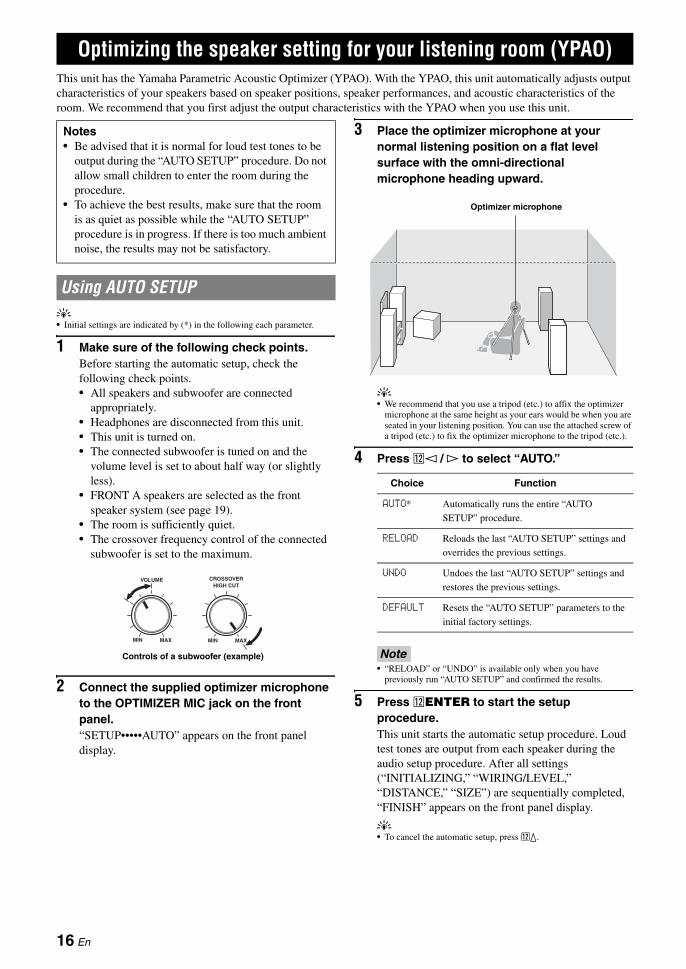
3 Place the optimizer microphone at your normal listening position on a flat level surface with the omni-directional microphone heading upward.
y• We recommend that you use a tripod (etc.) to affix the optimizer
microphone at the same height as your ears would be when you are seated in your listening position. You can use the attached screw of a tripod (etc.) to fix the optimizer microphone to the tripod (etc.).
4 Press ll / h to select “AUTO.”
Note• “RELOAD” or “UNDO” is available only when you have
previously run “AUTO SETUP” and confirmed the results.
5 Press lENTER to start the setup procedure.This unit starts the automatic setup procedure. Loud test tones are output from each speaker during the audio setup procedure. After all settings (“INITIALIZING,” “WIRING/LEVEL,” “DISTANCE,” “SIZE”) are sequentially completed, “FINISH” appears on the front panel display.
y• To cancel the automatic setup, press lk.
Optimizing the speaker setting for your listening room (YPAO)
Notes• Be advised that it is normal for loud test tones to be
output during the “AUTO SETUP” procedure. Do not allow small children to enter the room during the procedure.
• To achieve the best results, make sure that the room is as quiet as possible while the “AUTO SETUP” procedure is in progress. If there is too much ambient noise, the results may not be satisfactory.
Using AUTO SETUP
VOLUME
MIN MAX MIN MAX
CROSSOVER HIGH CUT
Controls of a subwoofer (example)
Choice Function
AUTO* Automatically runs the entire “AUTO
SETUP” procedure.
RELOAD Reloads the last “AUTO SETUP” settings and
overrides the previous settings.
UNDO Undoes the last “AUTO SETUP” settings and
restores the previous settings.
DEFAULT Resets the “AUTO SETUP” parameters to the
initial factory settings.
Optimizer microphone
16 En

Optimizing the speaker setting for your listening room (YPAO)E
ng
lishIN
TR
OD
UC
TIO
NA
DD
ITIO
NA
L
INF
OR
MA
TIO
NA
PP
EN
DIX
PR
EPA
RA
TIO
NB
AS
IC
OP
ER
AT
ION
AD
VAN
CE
D
OP
ER
AT
ION
Notes• During the automatic setup procedure, do not perform any
operation on this unit.• We recommend that you get out of the room while this unit is in the
auto setup procedure. It takes approximately 3 minutes for this unit to complete the auto setup procedure.
6 When all measurements are completed successfully, “FINISH” appears on the front panel display.The result of the automatic setup for each speaker appears in order on the front panel display.
y• To display the result of the automatic setup again, press lk / n
repeatedly.
Notes• If you select “RELOAD” in step 4, no test tones are output.• If an error occurs during the “AUTO:CHECK” procedure, the
setup procedure is canceled and an error screen appears. For details, see “If an error screen appears” on page 17.
• When this unit detects potential problems during the “AUTO SETUP” procedure, “WARNING” and the warning messages appear after this unit displays the result of the automatic setup. For details, refer to the “AUTO SETUP” section in “Troubleshooting” on page 43.
• The distance measurement result may be longer than the actual distance depending on the characteristics of your subwoofer.
7 Press ll / h to select “SET” or “CANCEL.”
8 Press lENTER to confirm your selection.“AUTO SETUP” appears on the front panel display.
9 Press kMENU to exit from “SET MENU.”
10 Disconnect the optimizer microphone from this unit.The optimizer microphone is sensitive to heat. Keep it away from direct sunlight and do not place it on top of this unit.
y• If you change speakers, speaker positions, or the layout of your
listening environment, run “AUTO SETUP” again to recalibrate your system.
• When you want to check the result of the automatic setup in detail or manually adjust the parameters, use “MANUAL SETUP” (see page 31).
■ If an error screen appearsIf this unit detects the potential problems, an error message appears on the front panel display during the automatic setup.For details about each error message, see the “AUTO SETUP” section in “Troubleshooting” on page 43.After a few seconds later, the following choices appear.Press ll / h to select “RETRY” or “EXIT” and then press lENTER.
■ If “WARNING” appearsWhen this unit detects potential problems during the automatic setup procedure, “WARNING” appears on the front panel display after result of each speaker. Check the warning messages to correct your speaker settings.
Note• Warnings differ from errors in that warnings do not cancel the automatic
setup procedure.
Press ln to display the detailed information about the warning.The detailed information about the warning is displayed and the indicators of inapplicable speakers blink on the front panel display.
y• For details about each warning message, see the “AUTO SETUP” section
in “Troubleshooting” on page 43.
Choice Function
SET* Confirms the “AUTO SETUP” results.
CANCEL Cancels the “AUTO SETUP” results.
FL: 3.3m +2
The distance between the speaker and the listening position
The result of the adjustment of the volume level
SpeakerFL/FR: Front left/right
C: CenterSL/SR: Surround left/right
SW: Subwoofer
Choice Function
RETRY* Starts the “AUTO SETUP” again.
EXIT Exits from the “AUTO SETUP” procedure.
PHASE REVERSEDLFE
L C RSL SR
Flashes
17 En
BASIC OPERATION
1 Turn on external components (TV, DVD player, etc.) connected to this unit.
2 Press CSPEAKERS repeatedly to select the front speakers you want to use.The respective speaker indicators lights up on the front panel display.
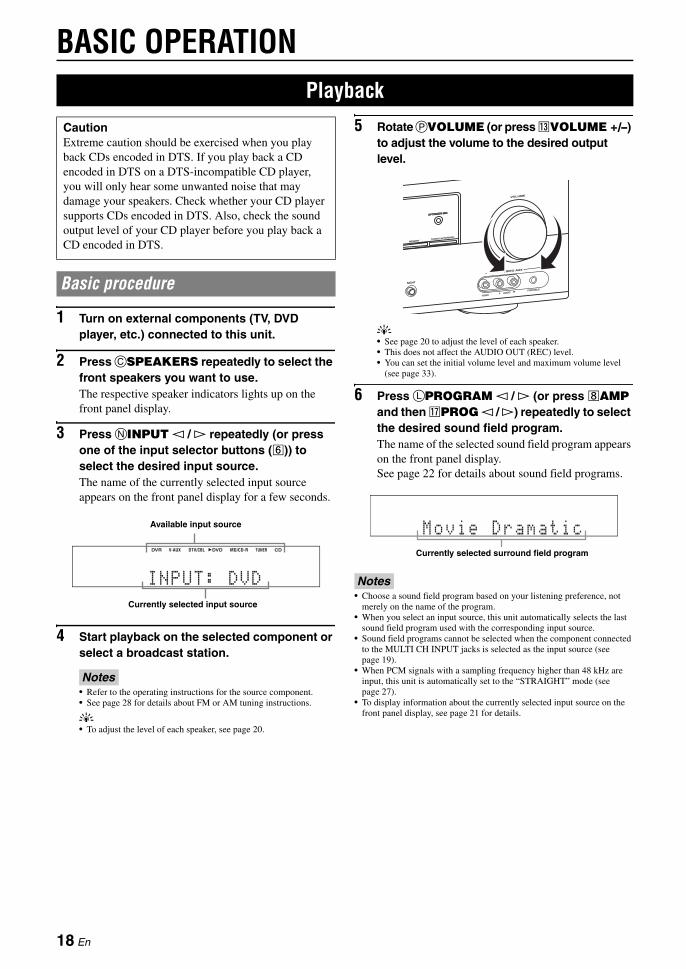
3 Press NINPUT l / h repeatedly (or press one of the input selector buttons (f)) to select the desired input source.The name of the currently selected input source appears on the front panel display for a few seconds.
4 Start playback on the selected component or select a broadcast station.
Notes• Refer to the operating instructions for the source component.• See page 28 for details about FM or AM tuning instructions.
y• To adjust the level of each speaker, see page 20.
5 Rotate PVOLUME (or press mVOLUME +/–) to adjust the volume to the desired output level.
y• See page 20 to adjust the level of each speaker.• This does not affect the AUDIO OUT (REC) level.• You can set the initial volume level and maximum volume level
(see page 33).
6 Press LPROGRAM l / h (or press hAMP and then qPROG l / h) repeatedly to select the desired sound field program.The name of the selected sound field program appears on the front panel display.See page 22 for details about sound field programs.
Notes• Choose a sound field program based on your listening preference, not
merely on the name of the program.• When you select an input source, this unit automatically selects the last
sound field program used with the corresponding input source.• Sound field programs cannot be selected when the component connected
to the MULTI CH INPUT jacks is selected as the input source (see page 19).
• When PCM signals with a sampling frequency higher than 48 kHz are input, this unit is automatically set to the “STRAIGHT” mode (see page 27).
• To display information about the currently selected input source on the front panel display, see page 21 for details.
Playback
CautionExtreme caution should be exercised when you play back CDs encoded in DTS. If you play back a CD encoded in DTS on a DTS-incompatible CD player, you will only hear some unwanted noise that may damage your speakers. Check whether your CD player supports CDs encoded in DTS. Also, check the sound output level of your CD player before you play back a CD encoded in DTS.
Basic procedure
��INPUT:�DVD
DVR DVD CDV-AUX DTV/CBL MD/CD-R TUNER
Available input source
Currently selected input source
Movie Dramatic
Currently selected surround field program
18 En
PlaybackE
ng
lishIN
TR
OD
UC
TIO
NA
DD
ITIO
NA
L
INF
OR
MA
TIO
NA
PP
EN
DIX
PR
EPA
RA
TIO
NB
AS
IC
OP
ER
AT
ION
AD
VAN
CE
D
OP
ER
AT
ION
Use the following features to select input jack or input source.
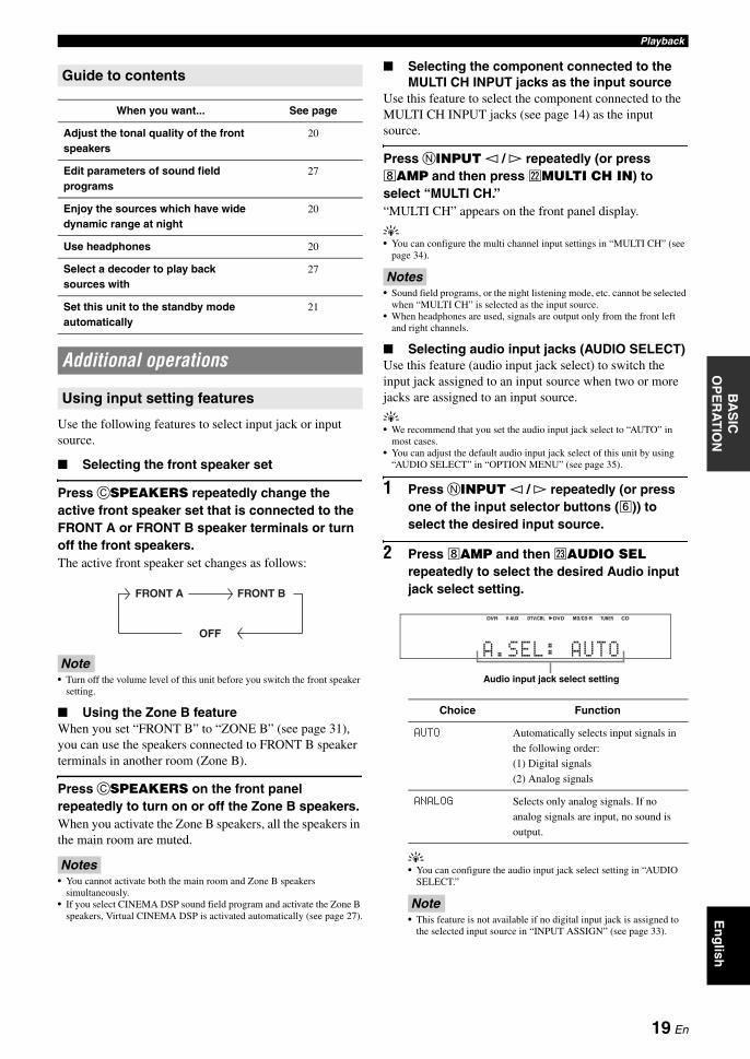
■ Selecting the front speaker set
Press CSPEAKERS repeatedly change the active front speaker set that is connected to the FRONT A or FRONT B speaker terminals or turn off the front speakers.The active front speaker set changes as follows:
Note• Turn off the volume level of this unit before you switch the front speaker
setting.
■ Using the Zone B featureWhen you set “FRONT B” to “ZONE B” (see page 31), you can use the speakers connected to FRONT B speaker terminals in another room (Zone B).
Press CSPEAKERS on the front panel repeatedly to turn on or off the Zone B speakers.When you activate the Zone B speakers, all the speakers in the main room are muted.
Notes• You cannot activate both the main room and Zone B speakers
simultaneously.• If you select CINEMA DSP sound field program and activate the Zone B
speakers, Virtual CINEMA DSP is activated automatically (see page 27).
■ Selecting the component connected to the MULTI CH INPUT jacks as the input source
Use this feature to select the component connected to the MULTI CH INPUT jacks (see page 14) as the input source.
Press NINPUT l / h repeatedly (or press hAMP and then press vMULTI CH IN) to select “MULTI CH.”“MULTI CH” appears on the front panel display.
y• You can configure the multi channel input settings in “MULTI CH” (see
page 34).
Notes• Sound field programs, or the night listening mode, etc. cannot be selected
when “MULTI CH” is selected as the input source.• When headphones are used, signals are output only from the front left
and right channels.
■ Selecting audio input jacks (AUDIO SELECT)Use this feature (audio input jack select) to switch the input jack assigned to an input source when two or more jacks are assigned to an input source.
y• We recommend that you set the audio input jack select to “AUTO” in
most cases.• You can adjust the default audio input jack select of this unit by using
“AUDIO SELECT” in “OPTION MENU” (see page 35).
1 Press NINPUT l / h repeatedly (or press one of the input selector buttons (f)) to select the desired input source.
2 Press hAMP and then wAUDIO SEL repeatedly to select the desired Audio input jack select setting.
y• You can configure the audio input jack select setting in “AUDIO
SELECT.”
Note• This feature is not available if no digital input jack is assigned to
the selected input source in “INPUT ASSIGN” (see page 33).
Guide to contents
When you want... See page
Adjust the tonal quality of the front speakers
20
Edit parameters of sound field programs
27
Enjoy the sources which have wide dynamic range at night
20
Use headphones 20
Select a decoder to play back sources with
27
Set this unit to the standby mode automatically
21
Additional operations
Using input setting features
FRONT A FRONT B
OFF
Choice Function
AUTO Automatically selects input signals in
the following order:
(1) Digital signals
(2) Analog signals
ANALOG Selects only analog signals. If no
analog signals are input, no sound is
output.
��A.SEL:�AUTO
DVR DVD CDV-AUX DTV/CBL MD/CD-R TUNER
Audio input jack select setting
19 En
Playback
Use the following features to adjust the audio output or speaker level.
■ Muting the audio output
Press eMUTE on the remote control to mute the audio output. Press eMUTE again to resume the audio output.
y• You can also rotate PVOLUME (or press mVOLUME +/–) to
resume the audio output.• You can configure the muting level by using “MUTE TYP.” in “SOUND
MENU” (see page 33).• The MUTE indicator flashes on the front panel display when the audio
output is muted and disappears from the front panel display when the audio output is resumed.
■ Adjusting the tonal qualityUse this feature to adjust the balance of bass and treble for the front left and right speaker channels.
Press KTONE CONTROL repeatedly to select “BASS” or “TREBLE” and then press LPROGRAM l / h to adjust the corresponding frequency response level.Control range: –10 dB to +10 dBEach choice is defined as follows.
Notes• Speaker and headphone adjustments are stored independently.• If you increase or decrease the high-frequency or low-frequency sound to
an extreme level, the tonal quality of the surround speakers may not match that of the front left and right speakers.
• This does not affect recorded material.
■ Adjusting the speaker levelYou can adjust the output level of each speaker while listening to a music source. This is also possible when playing sources input at the MULTI CH INPUT jacks.
Note• This operation will override the level adjustment made in “SP LEVEL”
(see page 32).
1 Press hAMP and then press jBAND LEVEL TITLE repeatedly to select the speaker you want to adjust.
y• Once you press jBAND LEVEL TITLE on the remote
control, you can also select the speaker by pressing lk / n.• The available speaker channels differ depending on the speaker
settings.
2 Press ll / h on the remote control (or press FPRESET/TUNING l / h) to adjust the speaker output level.Control range: –10.0 dB to +10.0 dB
Use the following features to utilize various useful functions equipped on this unit.
y• Initial settings are indicated by (*) in this following each parameter.
■ Using your headphones
Connect a pair of headphones with a stereo analog audio cable plug to the PHONES jack on the front panel.
y• When you select a sound field program, SILENT CINEMA mode is
automatically activated (see page 27).
Notes• When you connect headphones, no signals are output at the speaker
terminals.• All Dolby Digital and DTS audio signals are mixed down to the left and
right headphone channels.
■ Selecting the night listening modeThe night listening modes are designed to improve listenability at lower volumes or at night.
1 Press ONIGHT (or press hAMP and then uNIGHT) repeatedly to select “NIGHT:CINEMA” or “NIGHT:MUSIC.”Each choice is defined as follows.
y• When a night listening mode is selected, the NIGHT indicator
lights up on the front panel display.
Using audio features
Choice Function
BASS Adjusts the low-frequency response.
TREBLE Adjusts the high-frequency response.
Choice Description
FRONT L Front left speaker
FRONT R Front right speaker
CENTER Center speaker
SWFR Subwoofer
SUR.L Surround left speaker
SUR.R Surround right speaker
Using optional features
Choice Function
NIGHT:CINEMA Narrows the dynamic range of film
soundtracks and makes dialog easier to
hear at lower volumes.
NIGHT:MUSIC Preserves ease-of-listening for all
sounds.
NIGHT OFF Disables this feature.
20 En

PlaybackE
ng
lishIN
TR
OD
UC
TIO
NA
DD
ITIO
NA
L
INF
OR
MA
TIO
NA
PP
EN
DIX
PR
EPA
RA
TIO
NB
AS
IC
OP
ER
AT
ION
AD
VAN
CE
D
OP
ER
AT
ION
2 Press ll / h to adjust the effect level while “NIGHT:CINEMA” or “NIGHT:MUSIC” is displayed on the front panel display.Each choice is defined as follows.
y• “NIGHT:CINEMA” and “NIGHT:MUSIC” adjustments are stored
independently.
Notes• You cannot use the night listening modes in the following cases:
– when the component connected to the MULTI CH INPUT jacks is selected as the input source.
– when headphones are connected to the PHONES jack.– when the sampling frequency of the input sources are higher than 48
kHz.• The effect of night listening modes may vary depending on the input
source and surround sound settings you use.
■ Displaying the input source information (SIGNAL INFO)
You can display the format, sampling frequency, channel, bit rate and flag data of the current input signal.
1 Press hAMP and then press kMENU on the remote control.“AUTO SETUP” appears on the front panel display.
2 Press lk / n repeatedly to select “SIGNAL INFO” and then press lENTER.
3 Press lk / n to switch the displayed information.The following information about the input source appears on the front panel display.
4 Press kMENU on the remote control again to exit from “SET MENU.”
■ Using the sleep timerUse this feature to automatically set this unit to the standby mode after a certain amount of time. The sleep timer is useful when you are going to sleep while this unit is playing or recording from a source.
Press hAMP and then press xSLEEP repeatedly to set the amount of time.The sleep timer setting changes as follows.
Once the sleep timer is set, the SLEEP indicator lights up on the front panel display, and the display returns to the selected sound field program.
To cancel the sleep timerPress xSLEEP on the remote control repeatedly to select “SLEEP OFF.”
y• If you set the main zone to the standby mode, the sleep timer is
automatically canceled.
■ Playing video sources in the backgroundYou can combine a video image from a video source with sound from an audio source. For example, you can enjoy listening to classical music while viewing beautiful scenery from the video source on the video monitor.
Press the input selector buttons (f) on the remote control to select a video source and then an audio source.
Choice Function
MIN Slightly lowers the effect level.
MID* Moderately lowers the effect level.
MAX Considerably lowers the effect level.
Choice Description
FORMAT Signal format.
SAMPLING The number of samples per second
taken from a continuous signal to
make discrete signals.
CHANNEL The number of source channels in the
input signal (front/surround/LFE).
BITRATE The number of bits passing a given
point per second.
FLAG Flag data encoded in DTS, Dolby
Digital, or PCM signals that cue this
unit to automatically switch decoders.
;AUTO SETUP
SLEEP 120min SLEEP 90min
SLEEP 60minSLEEP 30minSLEEP OFF
DVD
V-AUX
DTV/CBL DVR
CD MD/CD-R TUNER
DVD
V-AUX
DTV/CBL DVR
DVD
DVD
MULTI CH IN9
Audio sources
Video sources
Video sources
Audio sources
21 En
Just by pressing one SCENE button, you can recall your favorite input source and sound field program according to the SCENE template that has been assigned to the SCENE button. The SCENE templates are built combinations of input sources and sound field programs.
This unit is equipped with 12 preset SCENE templates for various situations. The following SCENE templates are assigned to respective SCENE buttons in the default settings.
Notes*1 You must connect a cable TV or a satellite tuner to this unit in advance.
See page 13 for details.*2 You need to connect the supplied FM and AM antennas to this unit in
advance. See page 15 for details.*3 You have to tune into the desired radio station. See pages 28 to 29 for
the tuning information.*4 To achieve the best possible reception, orient the connected AM loop
antenna, or adjust the position of the end of the indoor FM antenna.
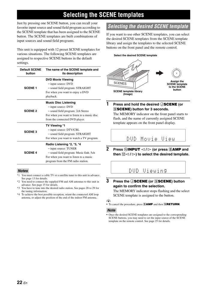
If you want to use other SCENE templates, you can select the desired SCENE templates from the SCENE template library and assign the templates to the selected SCENE buttons on the front panel and the remote control.
1 Press and hold the desired JSCENE (or iSCENE) button for 3 seconds.The MEMORY indicator on the front panel starts to flash, and the name of currently assigned SCENE template appears on the front panel display.
2 Press NINPUT l / h (or press hAMP and then ll / h) to select the desired template.
3 Press the JSCENE (or iSCENE) button again to confirm the selection.The MEMORY indicator stops flashing and the select SCENE template is assigned to the button.
y• To cancel the procedure, press hAMP and then nRETURN.
Note• Once the desired SCENE templates are assigned to the corresponding
SCENE buttons, you may need to set the input source of the SCENE template on the remote control. See page 25 for details.
Selecting the SCENE templates
Default SCENE button
The name of the SCENE template and its description
SCENE 1
DVD Movie Viewing– input source: DVD
– sound field program: STRAIGHT
For when you want to enjoy a DVD
playback.
SCENE 2
Music Disc Listening– input source: DVD
– sound field program: 2ch Stereo
For when you want to listen to a music disc
from the connected DVD player.
SCENE 3
TV Viewing *1– input source: DTV/CBL
– sound field program: STRAIGHT
For when you want to watch a TV program.
SCENE 4
Radio Listening *2, *3, *4– input source: TUNER
– sound field program: Music Enh. 5ch
For when you want to listen to a music
program from the FM radio station.
Selecting the desired SCENE template
1
Select the desired SCENE template
SCENE template library (Image)
Assign the SCENE template
to the SCENE button
DVD Movie View
DVD Viewing
22 En
Selecting the SCENE templatesE
ng
lishIN
TR
OD
UC
TIO
NA
DD
ITIO
NA
L
INF
OR
MA
TIO
NA
PP
EN
DIX
PR
EPA
RA
TIO
NB
AS
IC
OP
ER
AT
ION
AD
VAN
CE
D
OP
ER
AT
ION
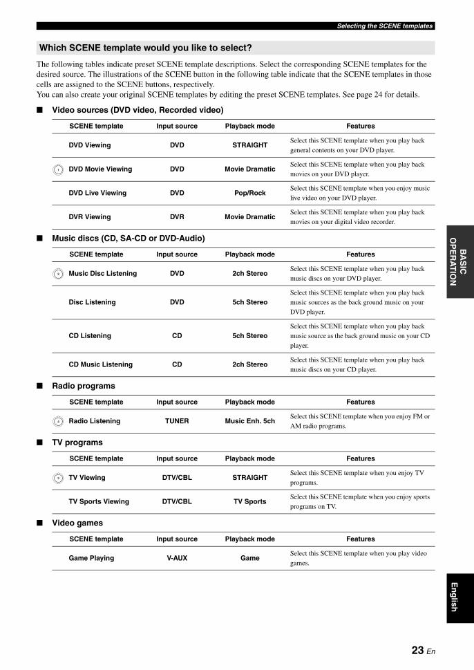
The following tables indicate preset SCENE template descriptions. Select the corresponding SCENE templates for the desired source. The illustrations of the SCENE button in the following table indicate that the SCENE templates in those cells are assigned to the SCENE buttons, respectively.You can also create your original SCENE templates by editing the preset SCENE templates. See page 24 for details.
■ Video sources (DVD video, Recorded video)
■ Music discs (CD, SA-CD or DVD-Audio)
■ Radio programs
■ TV programs
■ Video games
Which SCENE template would you like to select?
SCENE template Input source Playback mode Features
DVD Viewing DVD STRAIGHTSelect this SCENE template when you play back
general contents on your DVD player.
DVD Movie Viewing DVD Movie DramaticSelect this SCENE template when you play back
movies on your DVD player.
DVD Live Viewing DVD Pop/RockSelect this SCENE template when you enjoy music
live video on your DVD player.
DVR Viewing DVR Movie DramaticSelect this SCENE template when you play back
movies on your digital video recorder.
SCENE template Input source Playback mode Features
Music Disc Listening DVD 2ch StereoSelect this SCENE template when you play back
music discs on your DVD player.
Disc Listening DVD 5ch StereoSelect this SCENE template when you play back
music sources as the back ground music on your
DVD player.
CD Listening CD 5ch StereoSelect this SCENE template when you play back
music source as the back ground music on your CD
player.
CD Music Listening CD 2ch StereoSelect this SCENE template when you play back
music discs on your CD player.
SCENE template Input source Playback mode Features
Radio Listening TUNER Music Enh. 5chSelect this SCENE template when you enjoy FM or
AM radio programs.
SCENE template Input source Playback mode Features
TV Viewing DTV/CBL STRAIGHTSelect this SCENE template when you enjoy TV
programs.
TV Sports Viewing DTV/CBL TV SportsSelect this SCENE template when you enjoy sports
programs on TV.
SCENE template Input source Playback mode Features
Game Playing V-AUX GameSelect this SCENE template when you play video
games.
1
2
4
3
23 En
Selecting the SCENE templates
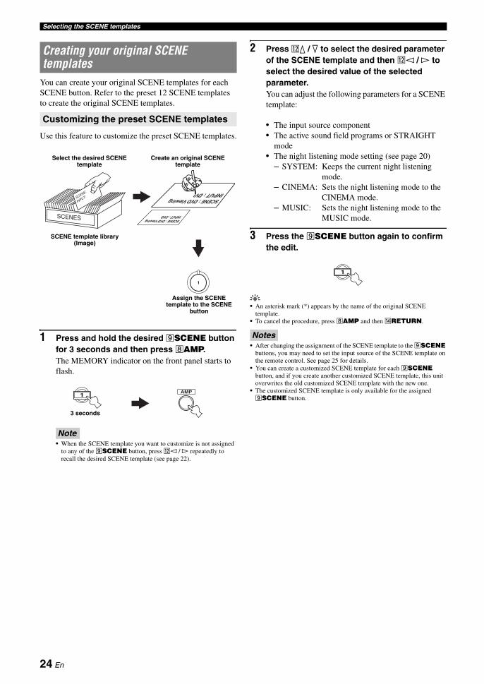
You can create your original SCENE templates for each SCENE button. Refer to the preset 12 SCENE templates to create the original SCENE templates.
Use this feature to customize the preset SCENE templates.
1 Press and hold the desired iSCENE button for 3 seconds and then press hAMP.The MEMORY indicator on the front panel starts to flash.
Note• When the SCENE template you want to customize is not assigned
to any of the iSCENE button, press ll / h repeatedly to recall the desired SCENE template (see page 22).
2 Press lk / n to select the desired parameter of the SCENE template and then ll / h to select the desired value of the selected parameter.You can adjust the following parameters for a SCENE template:
• The input source component• The active sound field programs or STRAIGHT
mode• The night listening mode setting (see page 20)
– SYSTEM: Keeps the current night listening mode.
– CINEMA: Sets the night listening mode to the CINEMA mode.
– MUSIC: Sets the night listening mode to the MUSIC mode.
3 Press the iSCENE button again to confirm the edit.
y• An asterisk mark (*) appears by the name of the original SCENE
template.• To cancel the procedure, press hAMP and then nRETURN.
Notes• After changing the assignment of the SCENE template to the iSCENE
buttons, you may need to set the input source of the SCENE template on the remote control. See page 25 for details.
• You can create a customized SCENE template for each iSCENE button, and if you create another customized SCENE template, this unit overwrites the old customized SCENE template with the new one.
• The customized SCENE template is only available for the assigned iSCENE button.
Creating your original SCENE templates
Customizing the preset SCENE templates
: DVD Viewing: DVD
SCENEINPUT
SCENE : DVD Viewing
1
Select the desired SCENE template
Create an original SCENE template
SCENE template library (Image)
Assign the SCENE template to the SCENE
button
AMP1
3 seconds
1
24 En

Selecting the SCENE templatesE
ng
lishIN
TR
OD
UC
TIO
NA
DD
ITIO
NA
L
INF
OR
MA
TIO
NA
PP
EN
DIX
PR
EPA
RA
TIO
NB
AS
IC
OP
ER
AT
ION
AD
VAN
CE
D
OP
ER
AT
ION
You can operate both this unit and the input source component by using the remote control. You must set the appropriate remote control code for each input source in advance (see page 38).
1 Press the desired iSCENE button on the remote control.
2 Press the desired buttons in the * area below to control the input source component of the selected SCENE template.
Note• These buttons control the input source component. See page 36 for
details of the function of each button.
If you customize the input source of the selected SCENE template, you must set the input source of the SCENE template on the remote control to operate the input source component correctly.
Press and hold the iSCENE button and the desired input selector button (f) for 3 seconds.
y• Press the iSCENE button again to operate the input source
component.
Using remote control on the SCENE feature
Controlling the input source components in the SCENE mode
Setting input source of the customized SCENE template on the remote control
REC
SUR. DECODE
NIGHTSTRAIGHT
MULTI CH IN AUDIO SEL SLEEP
ENHANCERl PROG h
TV MUTETV INPUT TV VOL
TV CH
POWER
AMP
STANDBYPOWER
MUTE
POWER
8
10
7
09
65
4321
ENT
DVD
V-AUX D E
DTV/CBL DVR
CD MD/CD-R TUNER
MENU VOLUMETITLE
ENTER
BAND LEVEL
DISPLAYRETURN
AVTV
SCENE
4321
A B C
* SCENE buttons
25 En
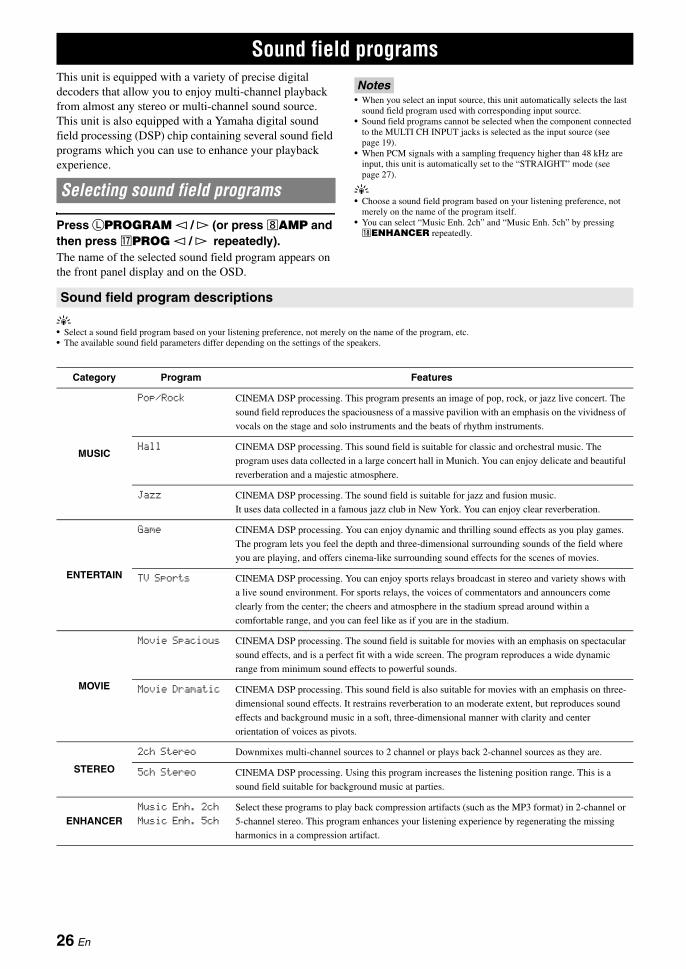
This unit is equipped with a variety of precise digital decoders that allow you to enjoy multi-channel playback from almost any stereo or multi-channel sound source. This unit is also equipped with a Yamaha digital sound field processing (DSP) chip containing several sound field programs which you can use to enhance your playback experience.
Press LPROGRAM l / h (or press hAMP and then press qPROG l / h repeatedly).The name of the selected sound field program appears on the front panel display and on the OSD.
Notes• When you select an input source, this unit automatically selects the last
sound field program used with corresponding input source.• Sound field programs cannot be selected when the component connected
to the MULTI CH INPUT jacks is selected as the input source (see page 19).
• When PCM signals with a sampling frequency higher than 48 kHz are input, this unit is automatically set to the “STRAIGHT” mode (see page 27).
y• Choose a sound field program based on your listening preference, not
merely on the name of the program itself.• You can select “Music Enh. 2ch” and “Music Enh. 5ch” by pressing rENHANCER repeatedly.
y• Select a sound field program based on your listening preference, not merely on the name of the program, etc.• The available sound field parameters differ depending on the settings of the speakers.
Sound field programs
Selecting sound field programs
Sound field program descriptions
Category Program Features
MUSIC
Pop/Rock CINEMA DSP processing. This program presents an image of pop, rock, or jazz live concert. The
sound field reproduces the spaciousness of a massive pavilion with an emphasis on the vividness of
vocals on the stage and solo instruments and the beats of rhythm instruments.
Hall CINEMA DSP processing. This sound field is suitable for classic and orchestral music. The
program uses data collected in a large concert hall in Munich. You can enjoy delicate and beautiful
reverberation and a majestic atmosphere.
Jazz CINEMA DSP processing. The sound field is suitable for jazz and fusion music.
It uses data collected in a famous jazz club in New York. You can enjoy clear reverberation.
ENTERTAIN
Game CINEMA DSP processing. You can enjoy dynamic and thrilling sound effects as you play games.
The program lets you feel the depth and three-dimensional surrounding sounds of the field where
you are playing, and offers cinema-like surrounding sound effects for the scenes of movies.
TV Sports CINEMA DSP processing. You can enjoy sports relays broadcast in stereo and variety shows with
a live sound environment. For sports relays, the voices of commentators and announcers come
clearly from the center; the cheers and atmosphere in the stadium spread around within a
comfortable range, and you can feel like as if you are in the stadium.
MOVIE
Movie Spacious CINEMA DSP processing. The sound field is suitable for movies with an emphasis on spectacular
sound effects, and is a perfect fit with a wide screen. The program reproduces a wide dynamic
range from minimum sound effects to powerful sounds.
Movie Dramatic CINEMA DSP processing. This sound field is also suitable for movies with an emphasis on three-
dimensional sound effects. It restrains reverberation to an moderate extent, but reproduces sound
effects and background music in a soft, three-dimensional manner with clarity and center
orientation of voices as pivots.
STEREO
2ch Stereo Downmixes multi-channel sources to 2 channel or plays back 2-channel sources as they are.
5ch Stereo CINEMA DSP processing. Using this program increases the listening position range. This is a
sound field suitable for background music at parties.
ENHANCERMusic Enh. 2ch
Music Enh. 5ch
Select these programs to play back compression artifacts (such as the MP3 format) in 2-channel or
5-channel stereo. This program enhances your listening experience by regenerating the missing
harmonics in a compression artifact.
26 En
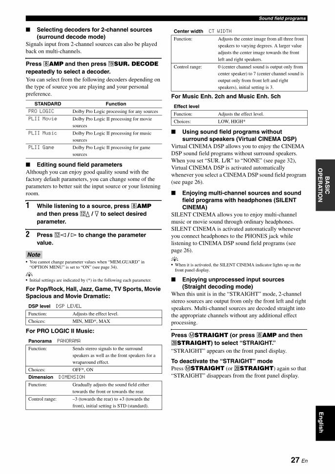
Sound field programsE
ng
lishIN
TR
OD
UC
TIO
NA
DD
ITIO
NA
L
INF
OR
MA
TIO
NA
PP
EN
DIX
PR
EPA
RA
TIO
NB
AS
IC
OP
ER
AT
ION
AD
VAN
CE
D
OP
ER
AT
ION
■ Selecting decoders for 2-channel sources (surround decode mode)
Signals input from 2-channel sources can also be played back on multi-channels.
Press hAMP and then press sSUR. DECODE repeatedly to select a decoder.You can select from the following decoders depending on the type of source you are playing and your personal preference.
■ Editing sound field parametersAlthough you can enjoy good quality sound with the factory default parameters, you can change some of the parameters to better suit the input source or your listening room.
1 While listening to a source, press hAMP and then press lk / n to select desired parameter.
2 Press ll / h to change the parameter value.
Note• You cannot change parameter values when “MEM.GUARD” in
“OPTION MENU” is set to “ON” (see page 34).
y• Initial settings are indicated by (*) in the following each parameter.
For Pop/Rock, Hall, Jazz, Game, TV Sports, Movie Spacious and Movie Dramatic:
For PRO LOGIC II Music:
For Music Enh. 2ch and Music Enh. 5ch
■ Using sound field programs without surround speakers (Virtual CINEMA DSP)
Virtual CINEMA DSP allows you to enjoy the CINEMA DSP sound field programs without surround speakers. When you set “SUR. L/R” to “NONE” (see page 32), Virtual CINEMA DSP is activated automatically whenever you select a CINEMA DSP sound field program (see page 26).
■ Enjoying multi-channel sources and sound field programs with headphones (SILENT CINEMA)
SILENT CINEMA allows you to enjoy multi-channel music or movie sound through ordinary headphones. SILENT CINEMA is activated automatically whenever you connect headphones to the PHONES jack while listening to CINEMA DSP sound field programs (see page 26).
y• When it is activated, the SILENT CINEMA indicator lights up on the
front panel display.
■ Enjoying unprocessed input sources (Straight decoding mode)
When this unit is in the “STRAIGHT” mode, 2-channel stereo sources are output from only the front left and right speakers. Multi-channel sources are decoded straight into the appropriate channels without any additional effect processing.
Press MSTRAIGHT (or press hAMP and then tSTRAIGHT) to select “STRAIGHT.”“STRAIGHT” appears on the front panel display.
To deactivate the “STRAIGHT” modePress MSTRAIGHT (or tSTRAIGHT) again so that “STRAIGHT” disappears from the front panel display.
STANDARD Function
PRO LOGIC Dolby Pro Logic processing for any sources
PLII Movie Dolby Pro Logic II processing for movie
sources
PLII Music Dolby Pro Logic II processing for music
sources
PLII Game Dolby Pro Logic II processing for game
sources
DSP level DSP LEVEL
Function: Adjusts the effect level.
Choices: MIN, MID*, MAX
Panorama PANORAMA
Function: Sends stereo signals to the surround
speakers as well as the front speakers for a
wraparound effect.
Choices: OFF*, ON
Dimension DIMENSION
Function: Gradually adjusts the sound field either
towards the front or towards the rear.
Control range: –3 (towards the rear) to +3 (towards the
front), initial setting is STD (standard).
Center width CT WIDTH
Function: Adjusts the center image from all three front
speakers to varying degrees. A larger value
adjusts the center image towards the front
left and right speakers.
Control range: 0 (center channel sound is output only from
center speaker) to 7 (center channel sound is
output only from front left and right
speakers), initial setting is 3.
Effect level
Function: Adjusts the effect level.
Choices: LOW, HIGH*
27 En
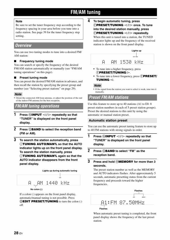
You can use two tuning modes to tune into a desired FM/AM station:
■ Frequency tuning modeYou can search or specify the frequency of the desired FM/AM station automatically or manually (see “FM/AM tuning operations” on this page).
■ Preset tuning modeYou can preset the desired FM/AM station in advance, and then recall the station by specifying the preset group and number (see “Selecting preset stations” on page 29).
Note• Orient the connected AM loop antenna, or adjust the position of the end
of the indoor FM antenna for the best reception.
1 Press NINPUT l / h repeatedly so that “TUNER” is displayed on the front panel display.
2 Press GBAND to select the reception band (FM or AM).
3 To search the station automatically, press ITUNING AUTO/MAN’L so that the AUTO indicator lights up on the front panel display. To search the station manually, press ITUNING AUTO/MAN’L again so that the AUTO indicator disappears from the front panel display.
If a colon (:) appears on the front panel display, automatic/manual tuning is not possible. Press DEDIT PRESET/TUNING to turn the colon (:) off.
4 To begin automatic tuning, press FPRESET/TUNING l / h once. To tune into the desired station manually, press FPRESET/TUNING l / h repeatedly.When this unit is tuned into a station, the TUNED indicator lights up and the frequency of the received station is shown on the front panel display.
• To tune into a higher frequency, press FPRESET/TUNING h.
• To tune into a lower frequency, press FPRESET/TUNING l.
Note• If the signal from the station you want to select is weak, tune into it
manually.
Use this feature to store up to 40 stations (A1 to E8: 8 preset station numbers in each of 5 preset station groups). Preset the desired stations to this unit by using the automatic or manual station preset.
You can use the automatic preset tuning feature to store up to 40 FM stations with strong signals in order.
1 Press NINPUT l / h repeatedly so that “TUNER” is displayed on the front panel display.
2 Press GBAND to select “FM” as the reception band.
3 Press and hold HMEMORY for more than 3 seconds.The preset station number as well as the MEMORY and AUTO indicators flashes. After approximately 5 seconds, automatic presetting status from the current frequency and proceeds toward the higher frequencies.
When automatic preset tuning is completed, the front panel display shows the frequency of the last preset station.
FM/AM tuning
NoteBe sure to set the tuner frequency step according to the frequency spacing in your area before you tune into a radio station. See page 39 for the tuner frequency step setting.
Overview
FM/AM tuning operations
AUTO
A AM 1440 kHz
Lights up during automatic tuning
No colon (:)
Preset FM/AM stations
Automatic station preset
AUTO TUNED
A AM 1530 kHz
Lights up
AUTO MEMORY
A1:FM 87.50MHz
Flashes
Flashes
28 En
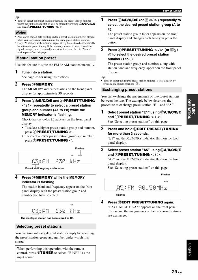
FM/AM tuningE
ng
lishIN
TR
OD
UC
TIO
NA
DD
ITIO
NA
L
INF
OR
MA
TIO
NA
PP
EN
DIX
PR
EPA
RA
TIO
NB
AS
IC
OP
ER
AT
ION
AD
VAN
CE
D
OP
ER
AT
ION
y• You can select the preset station group and the preset station number
where the first received station will be stored by pressing EA/B/C/D/E and then FPRESET/TUNING l / h.
Notes• Any stored station data existing under a preset station number is cleared
when you store a new station under the same preset station number.• Only FM stations with sufficient signal strength are stored automatically
by automatic preset tuning. If the station you want to store is weak in signal strength, tune it manually and store it as described in “Manual station preset” on this page.
Use this feature to store the FM or AM stations manually.
1 Tune into a station.See page 28 for using instructions.
2 Press HMEMORY.The MEMORY indicator flashes on the front panel display for approximately 30 seconds.
3 Press EA/B/C/D/E and FPRESET/TUNING l / h repeatedly to select a preset station group and number (A1 to E8) while the MEMORY indicator is flashing.Check that the colon (:) appears on the front panel display.• To select a higher preset station group and number,
press FPRESET/TUNING h.• To select a lower preset station group and number,
press FPRESET/TUNING l.
4 Press HMEMORY while the MEMORY indicator is flashing.The station band and frequency appear on the front panel display with the preset station group and number you have selected.
You can tune into any desired station simply by selecting the preset station group and number under which it is stored.
1 Press EA/B/C/D/E (or ll / h) repeatedly to select the desired preset station group (A to E).The preset station group letter appears on the front panel display and changes each time you press the button.
2 Press FPRESET/TUNING l / h (or lk / n) to select the desired preset station number (1 to 8).The preset station group and number, along with station band and frequency, appear on the front panel display.
y• You can select the desired preset station number (1 to 8) directly by
pressing the numeric buttons (y).
You can exchange the assignments of two preset stations between the two. The example below describes the procedure to exchange preset station “E1” and “A5.”
1 Select preset station “E1” using EA/B/C/D/E and FPRESET/TUNING l / h.See “Selecting preset stations” on this page.
2 Press and hold DEDIT PRESET/TUNING for more than 3 seconds.“E1” and the MEMORY indicator flash on the front panel display.
3 Select preset station “A5” using EA/B/C/D/E and FPRESET/TUNING l / h.“A5” and the MEMORY indicator flash on the front panel display.See “Selecting preset stations” on this page.
4 Press DEDIT PRESET/TUNING again.“EXCHANGE E1-A5” appears on the front panel display and the assignments of the two preset stations are exchanged.
Manual station preset
Selecting preset stations
When performing this operation with the remote control, press fTUNER to select “TUNER” as the input source.
TUNED MEMORY
:C3 AM 630 kHz
Flashes
Preset station group and number
TUNED
:C3 AM 630 kHz
The displayed station has been stored as C3.
Exchanging preset stations
MEMORY
:A5 FM 90.50MHz
Flashes
Flashes
29 En
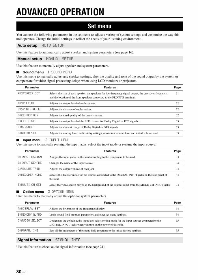
ADVANCED OPERATION
You can use the following parameters in the set menu to adjust a variety of system settings and customize the way this unit operates. Change the initial settings to reflect the needs of your listening environment.
Use this feature to automatically adjust speaker and system parameters (see page 16).
Use this feature to manually adjust speaker and system parameters.
■ Sound menu 1 SOUND MENUUse this menu to manually adjust any speaker settings, alter the quality and tone of the sound output by the system or compensate for video signal processing delays when using LCD monitors or projectors.
■ Input menu 2 INPUT MENUUse this menu to manually reassign the input jacks, select the input mode or rename the input source.
■ Option menu 3 OPTION MENUUse this menu to manually adjust the optional system parameters.
Use this feature to check audio signal information (see page 21).
Set menu
Auto setup AUTO SETUP
Manual setup MANUAL SETUP
Parameter Features Page
A)SPEAKER SET Selects the size of each speaker, the speakers for low-frequency signal output, the crossover frequency,
and the location of the front speakers connected to the FRONT B terminals.
31
B)SP LEVEL Adjusts the output level of each speaker. 32
C)SP DISTANCE Adjusts the distance of each speaker. 32
D)CENTER GEQ Adjusts the tonal quality of the center speaker. 32
E)LFE LEVEL Adjusts the output level of the LFE channel for Dolby Digital or DTS signals. 33
F)D.RANGE Adjusts the dynamic range of Dolby Digital or DTS signals. 33
G)AUDIO SET Adjusts the muting level, audio delay settings, maximum volume level and initial volume level. 33
Parameter Features Page
A)INPUT ASSIGN Assigns the input jacks on this unit according to the component to be used. 33
B)INPUT RENAME Changes the name of the input source. 34
C)VOLUME TRIM Adjusts the output volume of each jack. 34
D)DECODER MODE Selects the decoder mode for the sources connected to the DIGITAL INPUT jacks on the rear panel of
this unit.
34
E)MULTI CH SET Select the video source played in the background of the sources input from the MULTI CH INPUT jacks. 34
Parameter Features Page
A)DISPLAY SET Adjusts the brightness of the front panel display. 34
B)MEMORY GUARD Locks sound field program parameters and other set menu settings. 34
C)AUDIO SELECT Designates the default audio input jack select setting mode for the input sources connected to the
DIGITAL INPUT jacks when you turn on the power of this unit.
35
D)PARAM. INI Sets all the parameters of the sound field programs to the initial factory settings. 35
Signal information SIGNAL INFO
30 En
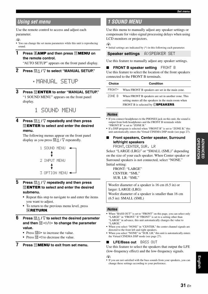
Set menuE
ng
lishIN
TR
OD
UC
TIO
NA
DD
ITIO
NA
L
INF
OR
MA
TIO
NA
PP
EN
DIX
PR
EPA
RA
TIO
NB
AS
IC
OP
ER
AT
ION
AD
VAN
CE
D
OP
ER
AT
ION
Use the remote control to access and adjust each parameter.
y• You can change the set menu parameters while this unit is reproducing
sound.
1 Press hAMP and then press kMENU on the remote control.“AUTO SETUP” appears on the front panel display.
2 Press lk / n to select “MANUAL SETUP.”
3 Press lENTER to enter “MANUAL SETUP.”“1 SOUND MENU” appears on the front panel display.
4 Press lk / n repeatedly and then press lENTER to select and enter the desired menu.The following menus appear on the front panel display as you press lk / n repeatedly.
5 Press lk / n repeatedly and then press lENTER to select and enter the desired submenu.• Repeat this step to navigate to and enter the items
you want to adjust.• To return to the previous menu level, press nRETURN.
6 Press lk / n to select the desired parameter and then ll / h to change the parameter value.• Press lh to increase the value.• Press ll to decrease the value.
7 Press kMENU to exit from set menu.
Use this menu to manually adjust any speaker settings or compensate for video signal processing delays when using LCD monitors or projectors.
y• Initial settings are indicated by (*) in this following each parameter.
Use this feature to manually adjust any speaker settings.
■ FRONT B speaker setting FRONT BUse this feature to select the location of the front speakers connected to the FRONT B terminals.
Notes• If you connect headphones to the PHONES jack on this unit, the sound is
output from both headphones and the FRONT B terminals while “FRONT B” is set to “ZONE B.”
• If a DSP program is selected when “FRONT B” is set to “ZONE B,” this unit automatically enters the Virtual CINEMA DSP mode (see page 27).
■ Front speakers, Center speaker, Surround left/right speakersFRONT, CENTER, SUR. LR
Select “LARGE (LRG)” or “SMALL (SML)” depending on the size of your each speaker. When Center speaker or Surround speakers is not connected, select “NONE.”Initial setting:
FRONT: “LARGE”CENTER: “SML”SUR. LR: “SML”
Notes• When “BASS OUT” is set to “FRONT” on this page, you can select only
“LARGE” in “FRONT.” If “FRONT” is set to a setting other than “LARGE” in advance, this unit automatically changes the value to “LARGE.”
• When you select “NONE” in “CENTER,” the center channel signals are directed to the front left and right speakers.
• When you select “NONE” in “SUR. LR,” this unit is automatically enters the Virtual CINEMA DSP mode (see page 27).
■ LFE/Bass out BASS OUTUse this feature to select the speakers that output the LFE (low-frequency effect) and the low-frequency signals.
y• If you are not satisfied with the bass sounds from your speakers, you can
change these settings according to your preference.
Using set menu
MANUAL SETUP .
1 SOUND MENU
1 SOUND MENU
2 INPUT MENU
3 OPTION MENU
1 SOUND MENU
Speaker settings A)SPEAKER SET
Choice Condition
FRONT* When FRONT B speakers are set in the main zone.
ZONE B When FRONT B speakers are set in another zone. This
setting mutes all the speakers in the main room when
FRONT B is selected by CSPEAKERS.
Woofer diameter of a speaker is 16 cm (6.5 in) or larger: LARGE (LRG)Woofer diameter of a speaker is smaller than 16 cm (6.5 in): SMALL (SML)
31 En
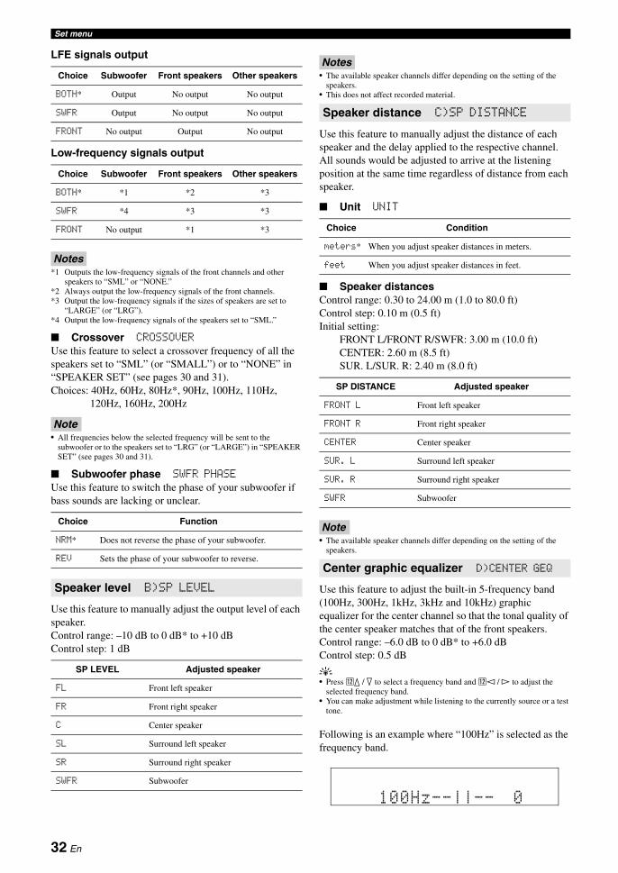
Set menu
LFE signals output
Low-frequency signals output
Notes*1 Outputs the low-frequency signals of the front channels and other
speakers to “SML” or “NONE.”*2 Always output the low-frequency signals of the front channels.*3 Output the low-frequency signals if the sizes of speakers are set to
“LARGE” (or “LRG”).*4 Output the low-frequency signals of the speakers set to “SML.”
■ Crossover CROSSOVERUse this feature to select a crossover frequency of all the speakers set to “SML” (or “SMALL”) or to “NONE” in “SPEAKER SET” (see pages 30 and 31).Choices: 40Hz, 60Hz, 80Hz*, 90Hz, 100Hz, 110Hz,
120Hz, 160Hz, 200Hz
Note• All frequencies below the selected frequency will be sent to the
subwoofer or to the speakers set to “LRG” (or “LARGE”) in “SPEAKER SET” (see pages 30 and 31).
■ Subwoofer phase SWFR PHASEUse this feature to switch the phase of your subwoofer if bass sounds are lacking or unclear.
Use this feature to manually adjust the output level of each speaker.Control range: –10 dB to 0 dB* to +10 dBControl step: 1 dB
Notes• The available speaker channels differ depending on the setting of the
speakers.• This does not affect recorded material.
Use this feature to manually adjust the distance of each speaker and the delay applied to the respective channel. All sounds would be adjusted to arrive at the listening position at the same time regardless of distance from each speaker.
■ Unit UNIT
■ Speaker distancesControl range: 0.30 to 24.00 m (1.0 to 80.0 ft)Control step: 0.10 m (0.5 ft)Initial setting:
FRONT L/FRONT R/SWFR: 3.00 m (10.0 ft)CENTER: 2.60 m (8.5 ft)SUR. L/SUR. R: 2.40 m (8.0 ft)
Note• The available speaker channels differ depending on the setting of the
speakers.
Use this feature to adjust the built-in 5-frequency band (100Hz, 300Hz, 1kHz, 3kHz and 10kHz) graphic equalizer for the center channel so that the tonal quality of the center speaker matches that of the front speakers.Control range: –6.0 dB to 0 dB* to +6.0 dBControl step: 0.5 dB
y• Press lk / n to select a frequency band and ll / h to adjust the
selected frequency band.• You can make adjustment while listening to the currently source or a test
tone.
Following is an example where “100Hz” is selected as the frequency band.
Choice Subwoofer Front speakers Other speakers
BOTH* Output No output No output
SWFR Output No output No output
FRONT No output Output No output
Choice Subwoofer Front speakers Other speakers
BOTH* *1 *2 *3
SWFR *4 *3 *3
FRONT No output *1 *3
Choice Function
NRM* Does not reverse the phase of your subwoofer.
REV Sets the phase of your subwoofer to reverse.
Speaker level B)SP LEVEL
SP LEVEL Adjusted speaker
FL Front left speaker
FR Front right speaker
C Center speaker
SL Surround left speaker
SR Surround right speaker
SWFR Subwoofer
Speaker distance C)SP DISTANCE
Choice Condition
meters* When you adjust speaker distances in meters.
feet When you adjust speaker distances in feet.
SP DISTANCE Adjusted speaker
FRONT L Front left speaker
FRONT R Front right speaker
CENTER Center speaker
SUR. L Surround left speaker
SUR. R Surround right speaker
SWFR Subwoofer
Center graphic equalizer D)CENTER GEQ
100Hz--||-- 0
32 En

Set menuE
ng
lishIN
TR
OD
UC
TIO
NA
DD
ITIO
NA
L
INF
OR
MA
TIO
NA
PP
EN
DIX
PR
EPA
RA
TIO
NB
AS
IC
OP
ER
AT
ION
AD
VAN
CE
D
OP
ER
AT
ION
■ Test tone TESTUse this feature to make adjustments for “CENTER GEQ” while listening to a test tone.
Use this feature to adjust the output level of the LFE (low-frequency effect) channel according to the capacity of your subwoofer or headphones.Control range: –20 dB to 0 dB*Control step: 1 dB
■ Speaker LFE SP LFEAdjusts the speaker LFE level.
■ Headphone LFE HP LFEAdjusts the headphone LFE level.
Notes• Depending on the settings of “BASS OUT” (see page 31), some signals
may not be output at the SUBWOOFER OUTPUT jack.• The LFE channel carries low-frequency special effects which are only
added to certain scenes.• This setting is effective when the input signal contains the LFE channel.
Use this feature to select the amount of dynamic range compression to be applied to your speakers or headphones. This setting is effective only when this unit is decoding Dolby Digital and DTS signals.
■ Speaker dynamic range SP D.RAdjusts the speaker compression.
■ Headphone dynamic range HP D.RAdjusts the headphone compression.
Use this feature to adjust the overall audio settings of this unit.
■ Mute type MUTE TYP.Use this feature to adjust how much the mute function reduces the output volume (see page 20).
■ Audio delay A.DELAYUse this feature to delay the sound output and synchronize it with the video image. This may be necessary for certain LCD monitors or projectors.Control range: 0 ms* to 160 msControl step: 1 ms
■ Maximum volume MAX VOL.Use this feature to set the maximum volume level regardless of the original volume range. This feature is useful to avoid the unexpected loud sound. Control range: +16 dB*, +10 dB to –30 dBControl step: 5 dB
Note• The “MAX VOL.” setting takes priority over the “INI.VOL.” setting. For
example, if “INI.VOL.” is set to –20 dB and “MAX VOL.” is set to –30 dB, the volume level is automatically set to –30 dB when you turn on the power of this unit next time.
■ Initial volume INI.VOL.Use this feature to set the volume level when the power of this unit is turned on.Choices: Off*, –80 dB to +16 dBControl step: 1 dB
Note• The “MAX VOL.” setting takes priority over the “INI.VOL.” setting.
Use this menu to reassign the input jacks, select the input mode or rename the input source.
y• Initial settings are indicated by (*) in this following each parameter.
Use this feature to assign the input jacks according to the component to be used if the initial settings of this unit do not correspond to your needs.
Choices: CD, MD/CD-R, DVD, DTV/CBL, V-AUX, DVRInitial setting:
IN (1) (COAXIAL jack): DVDIN (2) (OPTICAL (DTV/CBL) jack): DTV/CBLIN (3) (OPTICAL (CD) jack): CD
Notes• You cannot select a specific item more than once.• You cannot assign the same input source to both “IN (2)” and “IN (3).”
For example, you assign “CD” to “IN (2),” “–––” appears in “IN (3).”• Once the input jacks are reassigned, you can select the corresponding
component by using NINPUT l / h (or the input selector buttons (f) on the remote control).
Choice Function
OFF* Stops test tones and output the currently.
ON Outputs test tones from the center and from left
speakers.
Low-frequency effect level E)LFE LEVEL
Dynamic range F)D.RANGE
Choice Function
MIN Adjusts the dynamic range to narrow.
STD Adjusts the dynamic range to medium.
MAX* Preserves the greatest amount of dynamic range.
Audio settings G)AUDIO SET
Choice Function
FULL* Completely mutes all the audio output.
-20dB Reduces the current volume by 20 dB.
2 INPUT MENU
Input assignment A)INPUT ASSIGN
33 En
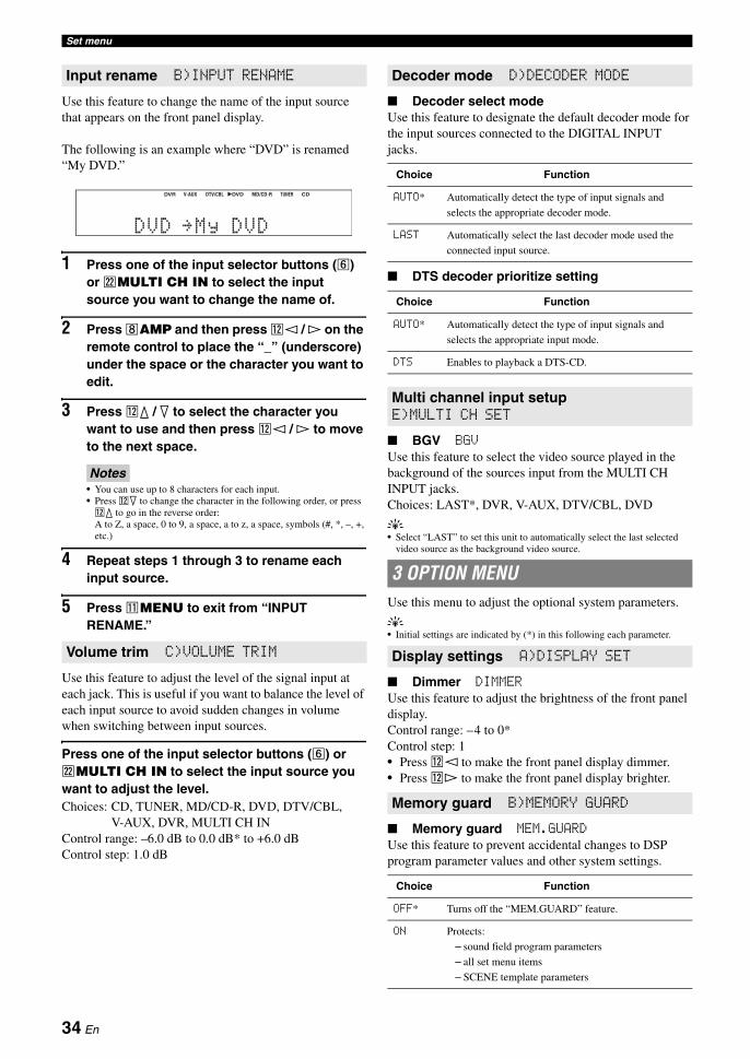
Set menu
Use this feature to change the name of the input source that appears on the front panel display.
The following is an example where “DVD” is renamed “My DVD.”
1 Press one of the input selector buttons (f) or vMULTI CH IN to select the input source you want to change the name of.
2 Press hAMP and then press ll / h on the remote control to place the “_” (underscore) under the space or the character you want to edit.
3 Press lk / n to select the character you want to use and then press ll / h to move to the next space.
Notes• You can use up to 8 characters for each input.• Press ln to change the character in the following order, or press lk to go in the reverse order: A to Z, a space, 0 to 9, a space, a to z, a space, symbols (#, *, –, +, etc.)
4 Repeat steps 1 through 3 to rename each input source.
5 Press kMENU to exit from “INPUT RENAME.”
Use this feature to adjust the level of the signal input at each jack. This is useful if you want to balance the level of each input source to avoid sudden changes in volume when switching between input sources.
Press one of the input selector buttons (f) or vMULTI CH IN to select the input source you want to adjust the level.Choices: CD, TUNER, MD/CD-R, DVD, DTV/CBL,
V-AUX, DVR, MULTI CH INControl range: –6.0 dB to 0.0 dB* to +6.0 dBControl step: 1.0 dB
■ Decoder select modeUse this feature to designate the default decoder mode for the input sources connected to the DIGITAL INPUT jacks.
■ DTS decoder prioritize setting
■ BGV BGVUse this feature to select the video source played in the background of the sources input from the MULTI CH INPUT jacks.Choices: LAST*, DVR, V-AUX, DTV/CBL, DVD
y• Select “LAST” to set this unit to automatically select the last selected
video source as the background video source.
Use this menu to adjust the optional system parameters.
y• Initial settings are indicated by (*) in this following each parameter.
■ Dimmer DIMMERUse this feature to adjust the brightness of the front panel display.Control range: –4 to 0*Control step: 1• Press ll to make the front panel display dimmer.• Press lh to make the front panel display brighter.
■ Memory guard MEM.GUARDUse this feature to prevent accidental changes to DSP program parameter values and other system settings.
Input rename B)INPUT RENAME
Volume trim C)VOLUME TRIM
DVR pDVD CDV-AUX DTV/CBL MD/CD-R TUNER
DVD My DVD
Decoder mode D)DECODER MODE
Choice Function
AUTO* Automatically detect the type of input signals and
selects the appropriate decoder mode.
LAST Automatically select the last decoder mode used the
connected input source.
Choice Function
AUTO* Automatically detect the type of input signals and
selects the appropriate input mode.
DTS Enables to playback a DTS-CD.
Multi channel input setup E)MULTI CH SET
3 OPTION MENU
Display settings A)DISPLAY SET
Memory guard B)MEMORY GUARD
Choice Function
OFF* Turns off the “MEM.GUARD” feature.
ON Protects:
– sound field program parameters
– all set menu items
– SCENE template parameters
34 En
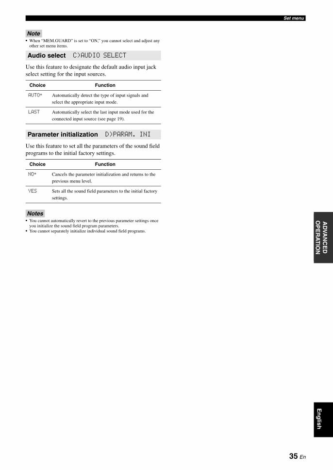
Set menuE
ng
lishIN
TR
OD
UC
TIO
NA
DD
ITIO
NA
L
INF
OR
MA
TIO
NA
PP
EN
DIX
PR
EPA
RA
TIO
NB
AS
IC
OP
ER
AT
ION
AD
VAN
CE
D
OP
ER
AT
ION
Note• When “MEM.GUARD” is set to “ON,” you cannot select and adjust any
other set menu items.
Use this feature to designate the default audio input jack select setting for the input sources.
Use this feature to set all the parameters of the sound field programs to the initial factory settings.
Notes• You cannot automatically revert to the previous parameter settings once
you initialize the sound field program parameters.• You cannot separately initialize individual sound field programs.
Audio select C)AUDIO SELECT
Choice Function
AUTO* Automatically detect the type of input signals and
select the appropriate input mode.
LAST Automatically select the last input mode used for the
connected input source (see page 19).
Parameter initialization D)PARAM. INI
Choice Function
NO* Cancels the parameter initialization and returns to the
previous menu level.
YES Sets all the sound field parameters to the initial factory
settings.
35 En
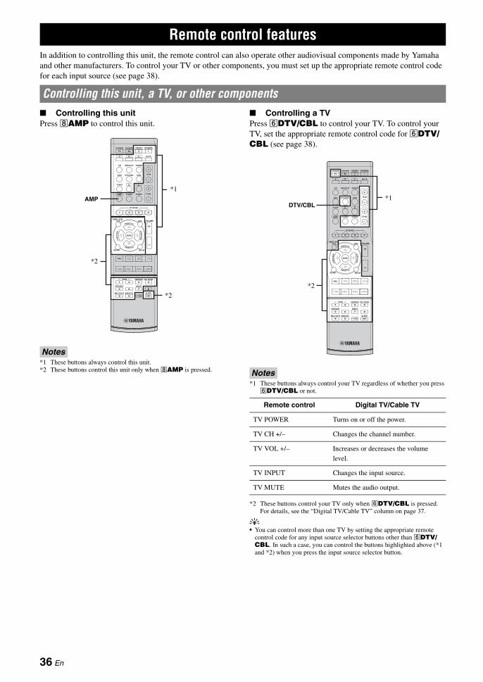
In addition to controlling this unit, the remote control can also operate other audiovisual components made by Yamaha and other manufacturers. To control your TV or other components, you must set up the appropriate remote control code for each input source (see page 38).-
■ Controlling this unitPress hAMP to control this unit.
Notes*1 These buttons always control this unit.*2 These buttons control this unit only when hAMP is pressed.
■ Controlling a TVPress fDTV/CBL to control your TV. To control your TV, set the appropriate remote control code for fDTV/CBL (see page 38).
Notes*1 These buttons always control your TV regardless of whether you press fDTV/CBL or not.
*2 These buttons control your TV only when fDTV/CBL is pressed. For details, see the “Digital TV/Cable TV” column on page 37.
y• You can control more than one TV by setting the appropriate remote
control code for any input source selector buttons other than fDTV/CBL. In such a case, you can control the buttons highlighted above (*1 and *2) when you press the input source selector button.
Remote control features
Controlling this unit, a TV, or other components
REC
SUR. DECODE
NIGHTSTRAIGHT
MULTI CH IN AUDIO SEL SLEEP
ENHANCERl PROG h
TV MUTETV INPUT TV VOL
TV CH
POWER
AMP
STANDBYPOWER
MUTE
POWER
8
10
7
09
65
4321
ENT
DVD
V-AUX D E
DTV/CBL DVR
CD MD/CD-R TUNER
MENU VOLUMETITLE
ENTER
BAND LEVEL
DISPLAYRETURN
AVTV
SCENE
4321
A B C
AMP
*2
*1
*2
Remote control Digital TV/Cable TV
TV POWER Turns on or off the power.
TV CH +/– Changes the channel number.
TV VOL +/– Increases or decreases the volume
level.
TV INPUT Changes the input source.
TV MUTE Mutes the audio output.
REC
SUR. DECODE
NIGHTSTRAIGHT
MULTI CH IN AUDIO SEL SLEEP
ENHANCERl PROG h
TV MUTETV INPUT TV VOL
TV CH
POWER
AMP
STANDBYPOWER
MUTE
POWER
8
10
7
09
65
4321
ENT
DVD
V-AUX D E
DTV/CBL DVR
CD MD/CD-R TUNER
MENU VOLUMETITLE
ENTER
BAND LEVEL
DISPLAYRETURN
AVTV
SCENE
4321
A B C
DTV/CBL
*2
*1
36 En

Remote control featuresE
ng
lishIN
TR
OD
UC
TIO
NA
DD
ITIO
NA
L
INF
OR
MA
TIO
NA
PP
EN
DIX
PR
EPA
RA
TIO
NB
AS
IC
OP
ER
AT
ION
AD
VAN
CE
D
OP
ER
AT
ION
■ Controlling other componentsPress one of the input selector buttons (f) or A to E buttons to control other components. You must set the appropriate remote control code for each input source in advance (see page 38). The following table shows the function of each control button used to control other components assigned to each input selector button. Be advised that some buttons may not correctly operate the selected component.
y• The remote control has 13 modes (input areas) to control components so
that the remote control can operate up to 13 different components.• When you press one of the optional component control area buttons (A to
E), you can control the desired component without changing the input source of this unit.
Notes*1 This button is operational only when the original remote control supplied with the component has a POWER button.*2 These buttons operate your DVD recorder only when you set the appropriate remote control code for DVR (see page 38).
TV MUTETV INPUT TV VOL
TV CH
POWER
AMP
STANDBYPOWER
MUTE
POWER
DVD
V-AUX D E
DTV/CBL DVR
CD MD/CD-R TUNER
AVTV
SCENE
4321
A B C
REC
SUR. DECODE
NIGHTSTRAIGHT
MULTI CH IN AUDIO SEL SLEEP
ENHANCERl PROG h
8
10
7
09
65
4321
ENT
MENU VOLUMETITLE
ENTER
BAND LEVEL
DISPLAYRETURN
[1] [2] [7]
[8]
[9]
[3]
[4]
[5]
[6]
Remote controlDVD player/
recorderVCR
Digital TV/Cable TV
LD player CD playerMD/CD
recorderTuner
[1] AV POWER Power *1 Power *1 Power *2 Power *1 Power *1 Power *1
[2] TITLE Title Band
[3] PRESET/CH k Up VCR channel
up
Up Preset up
(1-8)
PRESET/CH n Down VCR channel
down
Down Preset down
(1-8)
A/B/C/D/E l Left Left Preset down
(A-E)
A/B/C/D/E h Right Right Preset up
(A-E)
ENTER Enter Enter
[4] RETURN Return Return
[5] REC Disc skip
(player)
Rec (recorder)
Rec Rec *2 Disc skip Rec
p Play Play Play *2 Play Play Play
w Search
backward
Search
backward
Search
backward *2
Search
backward
Search
backward
Search
backward
f Search
forward
Search
forward
Search
forward *2
Search
forward
Search
forward
Search
forward
e Pause Pause Pause *2 Pause Pause Pause
b Skip
backward
Skip
backward
Skip
backward *2
Skip
backward
Skip
backward
Skip
backward
a Skip forward Skip forward Skip forward
*2
Skip forward Skip forward Skip forward
s Stop Stop Stop *2 Stop Stop Stop
[6] 1-9, 0, +10 Numeric
buttons
Numeric
buttons
Numeric
buttons
Numeric
buttons
Numeric
buttons
Numeric
buttons
Preset stations
(1-8)
[7] MENU Menu Menu
[8] DISPLAY Display Display Display Display Display Display
[9] ENT Title/Index Enter Enter Chapter/Time Index Index
37 En

Remote control features
You can control other components by setting the appropriate remote control codes. For a complete list of available remote control codes, refer to “List of remote control codes” at the end of this manual.
Remote control code default settings
Note• You may not be able to operate your Yamaha component even if a
Yamaha remote control code is preset as listed above. In this case, try setting another Yamaha remote control code.
1 While pressing and holding one of the input selector buttons (f) on the remote control to select the input area you want to set up, press bAV POWER for more than 3 seconds.
2 Press the numeric buttons (0 to 9) (y) to enter the four-digit remote control code for the component to be used.When the setting succeeds, “RemoteSetup OK” appears; however, when it dues not, “RemoteSetup NG” appears on the front panel display.
Notes• If the manufacturer of your component has more than one code, try each
of them until you find the correct one.• If you do not press any buttons within 30 seconds in step 2, the setup
process is canceled. If this happens, repeat the setup procedure.
■ Resetting all remote control codesUse this feature to clear all the remote control codes previously set and reset all of them to the initial factory settings.
1 While pressing and holding hAMP, press bAV POWER for more than 3 seconds.
2 Press the numeric buttons (y) to enter the code number “9981.”“RemoteSetup OK” appears on the front panel display, and the remote control codes previously set are cleared and reset to the initial factory settings.
y• If you do not press any buttons within 30 seconds after step 1, the
clearing process is canceled. In this case, repeat the clearing procedure.
Setting remote control codes
Input source
Component category
ManufacturerDefault code
CD CD Yamaha 5013
MD/CD-R CD-R Yamaha 5001
TUNER TUNER Yamaha 5007
DVD DVD Yamaha 2000
DTV/CBL — — —
V-AUX TUNER Yamaha 5011
DVR DVR Yamaha 2011
A TUNER Yamaha 5012
B TUNER Yamaha 5009
C TUNER Yamaha 5017
D — — —
E — — —
DVD
V-AUX D E
DTV/CBL DVR
CD MD/CD-R TUNER
A B C
POWER
AV
While holding down
Press for 3 seconds
POWER
AV
AMP
While holding down Press for 3 seconds
38 En

En
glish
INT
RO
DU
CT
ION
AD
DIT
ION
AL
IN
FO
RM
AT
ION
AP
PE
ND
IXP
RE
PAR
AT
ION
BA
SIC
O
PE
RA
TIO
NA
DVA
NC
ED
O
PE
RA
TIO
N
This unit has additional menus that are displayed on the front panel display. The advanced setup menu offers additional operations to adjust and customize the way this unit operates. Change the initial settings (indicated by (*) in this following parameter) to reflect the needs of your listening environment.
Notes• Only ASTANDBY/ON, LPROGRAM l / h and MSTRAIGHT are effective while you are using the advanced setup menu.
• No other operations can be made while you are using the advanced setup menu.
• The advanced setup menu is only available on the front panel display.
1 Press ASTANDBY/ON on the front panel to set this unit to the standby mode.
2 Press and hold KTONE CONTROL and then press ASTANDBY/ON to turn on this unit.This unit turns on, and the advanced setup menu appears on the front panel display.
3 Press LPROGRAM l / h to select the parameter you want to adjust.The name of the selected parameter appears on the front panel display.
4 Press MSTRAIGHT repeatedly to change the selected parameter setting.
5 Press ASTANDBY/ON to confirm your selection and set this unit to the standby mode.
y• The settings you made are reflected next time you turn on this unit.
■ Tuner frequency step TU(Asia and General models only)
Use this feature to set the tuner frequency step according to the frequency spacing in your area.Choices: AM10/FM100*, AM9/FM50• Select “AM10/FM100” for North, Central and South
America.• Select “AM9/FM50” for all other areas.
■ Initializing PRESETUse this feature to reset all the parameters of this unit to the initial factory settings.Choices: CANCEL*, RESET• Select “CANCEL” not to reset any parameters of this
unit.• Select “RESET” to reset the parameters of this unit.
Note• The initial factory settings are activated next time you turn on this unit.
Advanced setup
39 En
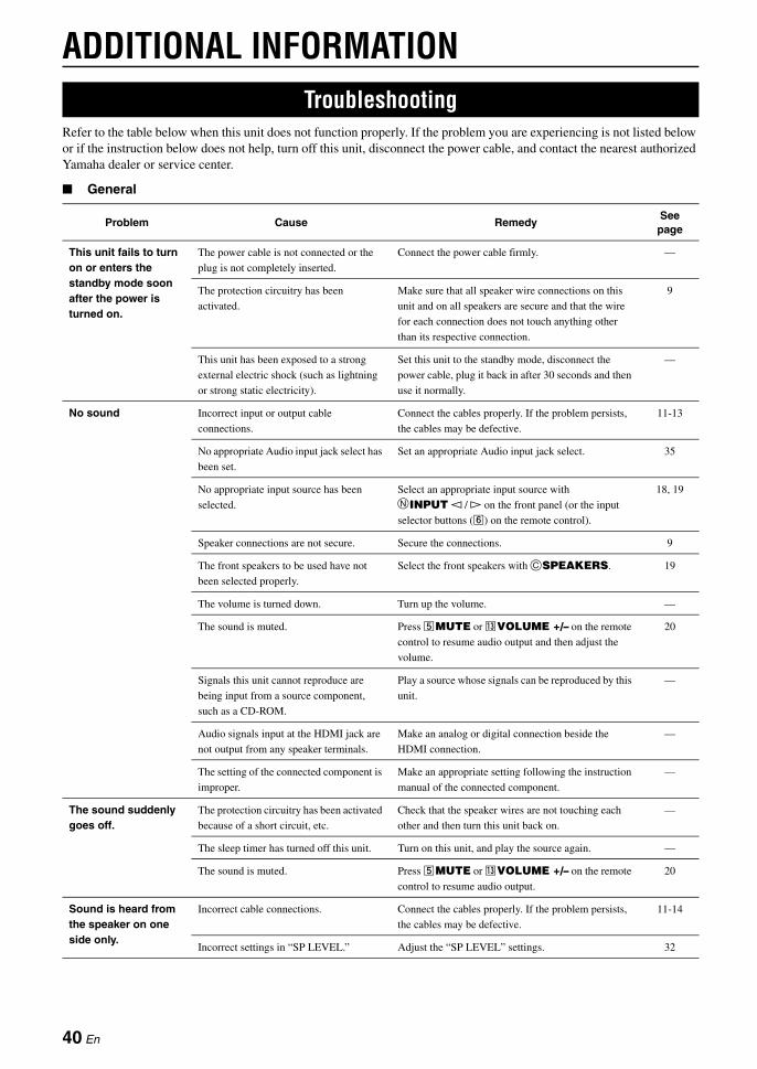
ADDITIONAL INFORMATION
Refer to the table below when this unit does not function properly. If the problem you are experiencing is not listed below or if the instruction below does not help, turn off this unit, disconnect the power cable, and contact the nearest authorized Yamaha dealer or service center.
■ General
Troubleshooting
Problem Cause RemedySee page
This unit fails to turn on or enters the standby mode soon after the power is turned on.
The power cable is not connected or the
plug is not completely inserted.
Connect the power cable firmly. —
The protection circuitry has been
activated.
Make sure that all speaker wire connections on this
unit and on all speakers are secure and that the wire
for each connection does not touch anything other
than its respective connection.
9
This unit has been exposed to a strong
external electric shock (such as lightning
or strong static electricity).
Set this unit to the standby mode, disconnect the
power cable, plug it back in after 30 seconds and then
use it normally.
—
No sound Incorrect input or output cable
connections.
Connect the cables properly. If the problem persists,
the cables may be defective.
11-13
No appropriate Audio input jack select has
been set.
Set an appropriate Audio input jack select. 35
No appropriate input source has been
selected.
Select an appropriate input source with NINPUT l / h on the front panel (or the input
selector buttons (f) on the remote control).
18, 19
Speaker connections are not secure. Secure the connections. 9
The front speakers to be used have not
been selected properly.
Select the front speakers with CSPEAKERS. 19
The volume is turned down. Turn up the volume. —
The sound is muted. Press eMUTE or mVOLUME +/– on the remote
control to resume audio output and then adjust the
volume.
20
Signals this unit cannot reproduce are
being input from a source component,
such as a CD-ROM.
Play a source whose signals can be reproduced by this
unit.
—
Audio signals input at the HDMI jack are
not output from any speaker terminals.
Make an analog or digital connection beside the
HDMI connection.
—
The setting of the connected component is
improper.
Make an appropriate setting following the instruction
manual of the connected component.
—
The sound suddenly goes off.
The protection circuitry has been activated
because of a short circuit, etc.
Check that the speaker wires are not touching each
other and then turn this unit back on.
—
The sleep timer has turned off this unit. Turn on this unit, and play the source again. —
The sound is muted. Press eMUTE or mVOLUME +/– on the remote
control to resume audio output.
20
Sound is heard from the speaker on one side only.
Incorrect cable connections. Connect the cables properly. If the problem persists,
the cables may be defective.
11-14
Incorrect settings in “SP LEVEL.” Adjust the “SP LEVEL” settings. 32
40 En
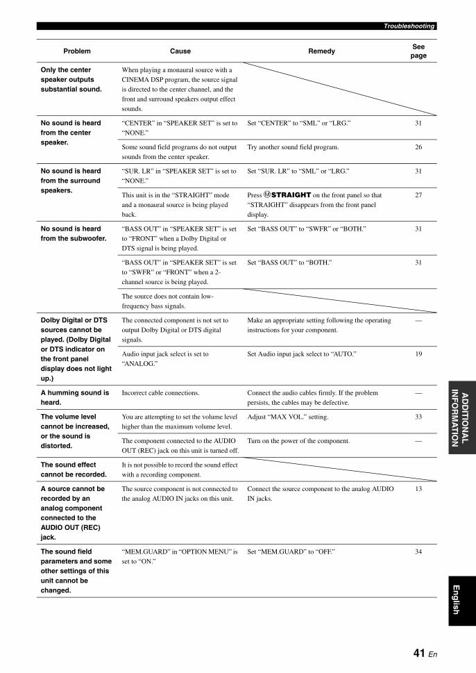
TroubleshootingE
ng
lishIN
TR
OD
UC
TIO
NA
DD
ITIO
NA
L
INF
OR
MA
TIO
NA
PP
EN
DIX
PR
EPA
RA
TIO
NB
AS
IC
OP
ER
AT
ION
AD
VAN
CE
D
OP
ER
AT
ION
Only the center speaker outputs substantial sound.
When playing a monaural source with a
CINEMA DSP program, the source signal
is directed to the center channel, and the
front and surround speakers output effect
sounds.
No sound is heard from the center speaker.
“CENTER” in “SPEAKER SET” is set to
“NONE.”
Set “CENTER” to “SML” or “LRG.” 31
Some sound field programs do not output
sounds from the center speaker.
Try another sound field program. 26
No sound is heard from the surround speakers.
“SUR. LR” in “SPEAKER SET” is set to
“NONE.”
Set “SUR. LR” to “SML” or “LRG.” 31
This unit is in the “STRAIGHT” mode
and a monaural source is being played
back.
Press MSTRAIGHT on the front panel so that
“STRAIGHT” disappears from the front panel
display.
27
No sound is heard from the subwoofer.
“BASS OUT” in “SPEAKER SET” is set
to “FRONT” when a Dolby Digital or
DTS signal is being played.
Set “BASS OUT” to “SWFR” or “BOTH.” 31
“BASS OUT” in “SPEAKER SET” is set
to “SWFR” or “FRONT” when a 2-
channel source is being played.
Set “BASS OUT” to “BOTH.” 31
The source does not contain low-
frequency bass signals.
Dolby Digital or DTS sources cannot be played. (Dolby Digital or DTS indicator on the front panel display does not light up.)
The connected component is not set to
output Dolby Digital or DTS digital
signals.
Make an appropriate setting following the operating
instructions for your component.
—
Audio input jack select is set to
“ANALOG.”
Set Audio input jack select to “AUTO.” 19
A humming sound is heard.
Incorrect cable connections. Connect the audio cables firmly. If the problem
persists, the cables may be defective.
—
The volume level cannot be increased, or the sound is distorted.
You are attempting to set the volume level
higher than the maximum volume level.
Adjust “MAX VOL.” setting. 33
The component connected to the AUDIO
OUT (REC) jack on this unit is turned off.
Turn on the power of the component. —
The sound effect cannot be recorded.
It is not possible to record the sound effect
with a recording component.
A source cannot be recorded by an analog component connected to the AUDIO OUT (REC) jack.
The source component is not connected to
the analog AUDIO IN jacks on this unit.
Connect the source component to the analog AUDIO
IN jacks.
13
The sound field parameters and some other settings of this unit cannot be changed.
“MEM.GUARD” in “OPTION MENU” is
set to “ON.”
Set “MEM.GUARD” to “OFF.” 34
Problem Cause RemedySee
page
41 En

Troubleshooting
■ Tuner
This unit does not operate properly.
The internal microcomputer has been
frozen by an external electric shock (such
as lightning or excessive static electricity)
or by a power supply with low voltage.
Disconnect the power cable from the AC wall outlet
and then plug it in again after about 30 seconds.
—
“CHECK SP WIRES” appears on the front panel display.
Speaker cables are short-circuited. Make sure all speaker cables are connected correctly. 9
There is noise interference from digital or radio frequency equipment.
This unit is too close to the digital or high-
frequency equipment.
Move this unit further away from such equipment. —
The picture is disturbed.
The video source uses scrambled or
encoded signals to prevent dubbing.
This unit suddenly enters the standby mode.
The internal temperature is too high and
the overheat protection circuitry has been
activated.
Wait about 1 hour for this unit to cool down and then
turn it back on.
—
Virtual CINEMA DSP is not activated.
“MULTI CH” is selected as the input
source.
Select an input source other than “MULTI CH.” 18
Headphones are connected to the
PHONES jack.
Disconnect the headphone plug from the PHONES
jack.
—
This unit is in the “5ch Stereo” mode. Exit from the “5ch Stereo” mode. 26
SILENT CINEMA is not activated.
“MULTI CH” is selected as the input
source.
Select an input source other than “MULTI CH.” 18
The unit is in the “2ch Stereo,”
“STRAIGHT” or “Music Enh.2ch” mode.
Exit from the “2ch Stereo,” “STRAIGHT” or “Music
Enh2ch” mode.
26
Problem Cause RemedySee
page
FM
FM stereo reception is noisy.
The characteristics of FM stereo
broadcasts may cause this problem
when the transmitter is too far away or
the antenna input is poor.
Check the antenna connections. 15
Try using a high-quality directional FM
antenna.
—
Use the manual tuning method. 28
There is distortion, and clear reception cannot be obtained even with a good FM antenna.
There is multi-path interference. Adjust the antenna position to eliminate
multi-path interference.
—
The desired station cannot be tuned into with the automatic tuning method.
The signal is too weak. Use a high-quality directional FM antenna. —
Use the manual tuning method. 28
Previously preset stations can no longer be tuned into.
This unit has been disconnected for a
long period.
Set preset stations. 28
Problem Cause RemedySee page
42 En
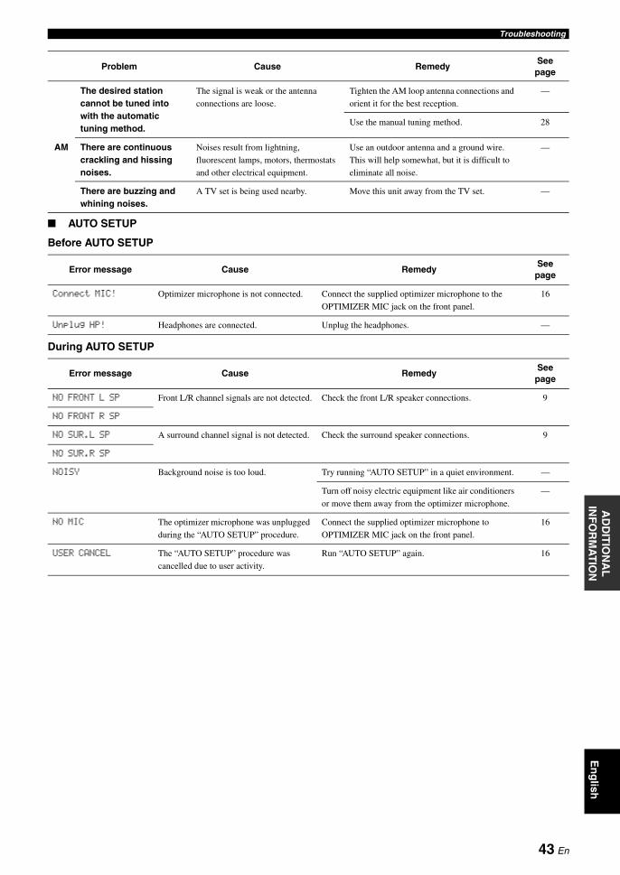
TroubleshootingE
ng
lishIN
TR
OD
UC
TIO
NA
DD
ITIO
NA
L
INF
OR
MA
TIO
NA
PP
EN
DIX
PR
EPA
RA
TIO
NB
AS
IC
OP
ER
AT
ION
AD
VAN
CE
D
OP
ER
AT
ION
■ AUTO SETUP
Before AUTO SETUP
During AUTO SETUP
AM
The desired station cannot be tuned into with the automatic tuning method.
The signal is weak or the antenna
connections are loose.
Tighten the AM loop antenna connections and
orient it for the best reception.
—
Use the manual tuning method. 28
There are continuous crackling and hissing noises.
Noises result from lightning,
fluorescent lamps, motors, thermostats
and other electrical equipment.
Use an outdoor antenna and a ground wire.
This will help somewhat, but it is difficult to
eliminate all noise.
—
There are buzzing and whining noises.
A TV set is being used nearby. Move this unit away from the TV set. —
Error message Cause RemedySee
page
Connect MIC! Optimizer microphone is not connected. Connect the supplied optimizer microphone to the
OPTIMIZER MIC jack on the front panel.
16
Unplug HP! Headphones are connected. Unplug the headphones. —
Error message Cause RemedySee
page
NO FRONT L SP Front L/R channel signals are not detected. Check the front L/R speaker connections. 9
NO FRONT R SP
NO SUR.L SP A surround channel signal is not detected. Check the surround speaker connections. 9
NO SUR.R SP
NOISY Background noise is too loud. Try running “AUTO SETUP” in a quiet environment. —
Turn off noisy electric equipment like air conditioners
or move them away from the optimizer microphone.
—
NO MIC The optimizer microphone was unplugged
during the “AUTO SETUP” procedure.
Connect the supplied optimizer microphone to
OPTIMIZER MIC jack on the front panel.
16
USER CANCEL The “AUTO SETUP” procedure was
cancelled due to user activity.
Run “AUTO SETUP” again. 16
Problem Cause RemedySee
page
43 En

Troubleshooting
After AUTO SETUP
Notes• If the “ERROR” or “WARNING” screens appears, check the cause of the problem, then run “AUTO SETUP” again.• If a warning message “PHASE REVERSED” appears, corrections are made, but they may not be optimal.• If a warning message “DISTANCE ERROR” or “LEVEL ERROR” appears, no corrections are made.
■ Remote control
■ Resetting the systemUse this feature to reset all the parameters of this unit to the initial factory settings. For details about the procedure of resetting the system, see “Initializing” in “Advanced setup” on page 39.
Warning message Cause RemedySee page
PHASE REVERSED Speaker polarity is not correct. This
message may appear depending on the
speakers even when the speakers are
connected correctly.
Check the speaker connections for proper polarity (+
or –).
9
DISTANCE ERROR The distance between the nearest speaker
and the furthest speaker is out of
adjustable range.
Bring the speaker closer to the listening position. —
LEVEL ERROR The difference of volume level among
speakers is excessive. (No level correction
is made.)
If “SWFR:TOO LOUD” or “SWFR:TOO LOW”
appears, adjust the output volume of the subwoofer.
16
Readjust the speaker installation so that all speakers
are set in locations with similar conditions.
—
Check the speaker connections. 9
Use speakers of similar quality. —
Problem Cause RemedySee page
The remote control does not work nor function properly.
Wrong distance or angle. The remote control functions within a maximum
range of 6 m (20 ft) and no more than 30 degrees off-
axis from the front panel.
8
Direct sunlight or lighting (from an
inverter type of fluorescent lamp, etc.) is
striking the remote control sensor of this
unit.
Reposition this unit. —
The batteries are weak. Replace all batteries. 8
The remote control code is not correctly
set.
Set the remote control code correctly using “List of
remote control codes” at the end of this manual.
38
Try setting another code for the same manufacturer
using “List of remote control codes” at the end of this
manual.
38
Even if the remote control code is
correctly set, there are some models that
do not respond to the remote control.
44 En
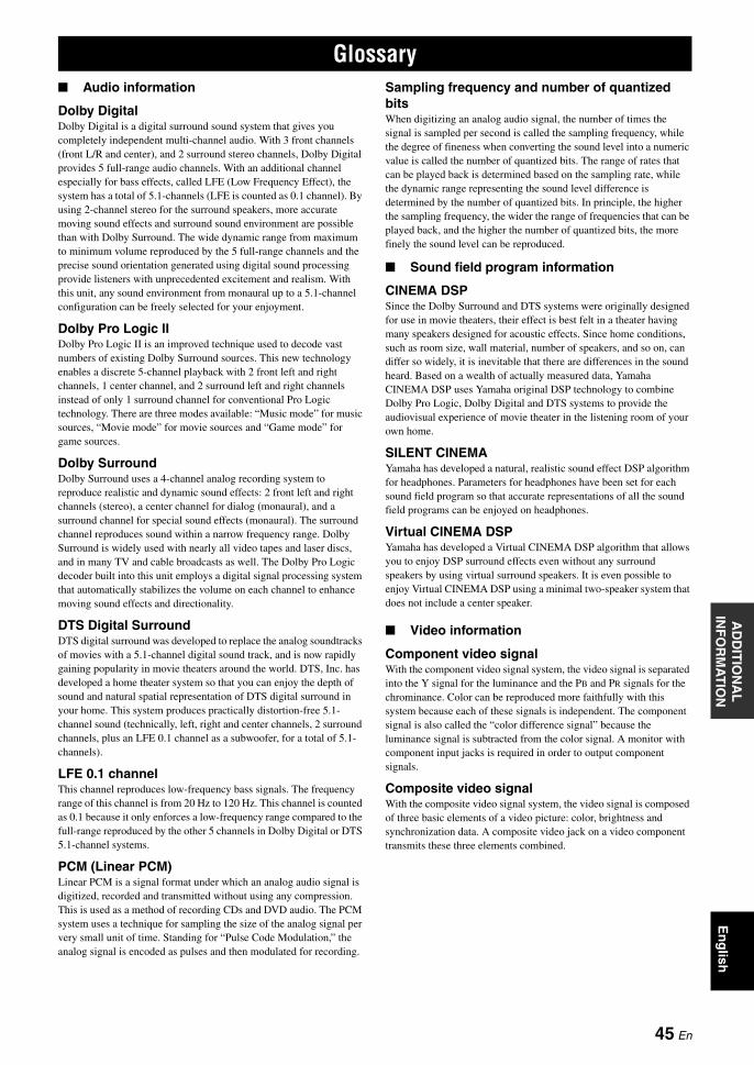
En
glish
INT
RO
DU
CT
ION
AD
DIT
ION
AL
IN
FO
RM
AT
ION
AP
PE
ND
IXP
RE
PAR
AT
ION
BA
SIC
O
PE
RA
TIO
NA
DVA
NC
ED
O
PE
RA
TIO
N
■ Audio information
Dolby DigitalDolby Digital is a digital surround sound system that gives you completely independent multi-channel audio. With 3 front channels (front L/R and center), and 2 surround stereo channels, Dolby Digital provides 5 full-range audio channels. With an additional channel especially for bass effects, called LFE (Low Frequency Effect), the system has a total of 5.1-channels (LFE is counted as 0.1 channel). By using 2-channel stereo for the surround speakers, more accurate moving sound effects and surround sound environment are possible than with Dolby Surround. The wide dynamic range from maximum to minimum volume reproduced by the 5 full-range channels and the precise sound orientation generated using digital sound processing provide listeners with unprecedented excitement and realism. With this unit, any sound environment from monaural up to a 5.1-channel configuration can be freely selected for your enjoyment.
Dolby Pro Logic IIDolby Pro Logic II is an improved technique used to decode vast numbers of existing Dolby Surround sources. This new technology enables a discrete 5-channel playback with 2 front left and right channels, 1 center channel, and 2 surround left and right channels instead of only 1 surround channel for conventional Pro Logic technology. There are three modes available: “Music mode” for music sources, “Movie mode” for movie sources and “Game mode” for game sources.
Dolby SurroundDolby Surround uses a 4-channel analog recording system to reproduce realistic and dynamic sound effects: 2 front left and right channels (stereo), a center channel for dialog (monaural), and a surround channel for special sound effects (monaural). The surround channel reproduces sound within a narrow frequency range. Dolby Surround is widely used with nearly all video tapes and laser discs, and in many TV and cable broadcasts as well. The Dolby Pro Logic decoder built into this unit employs a digital signal processing system that automatically stabilizes the volume on each channel to enhance moving sound effects and directionality.
DTS Digital SurroundDTS digital surround was developed to replace the analog soundtracks of movies with a 5.1-channel digital sound track, and is now rapidly gaining popularity in movie theaters around the world. DTS, Inc. has developed a home theater system so that you can enjoy the depth of sound and natural spatial representation of DTS digital surround in your home. This system produces practically distortion-free 5.1-channel sound (technically, left, right and center channels, 2 surround channels, plus an LFE 0.1 channel as a subwoofer, for a total of 5.1-channels).
LFE 0.1 channelThis channel reproduces low-frequency bass signals. The frequency range of this channel is from 20 Hz to 120 Hz. This channel is counted as 0.1 because it only enforces a low-frequency range compared to the full-range reproduced by the other 5 channels in Dolby Digital or DTS 5.1-channel systems.
PCM (Linear PCM)Linear PCM is a signal format under which an analog audio signal is digitized, recorded and transmitted without using any compression. This is used as a method of recording CDs and DVD audio. The PCM system uses a technique for sampling the size of the analog signal per very small unit of time. Standing for “Pulse Code Modulation,” the analog signal is encoded as pulses and then modulated for recording.
Sampling frequency and number of quantized bitsWhen digitizing an analog audio signal, the number of times the signal is sampled per second is called the sampling frequency, while the degree of fineness when converting the sound level into a numeric value is called the number of quantized bits. The range of rates that can be played back is determined based on the sampling rate, while the dynamic range representing the sound level difference is determined by the number of quantized bits. In principle, the higher the sampling frequency, the wider the range of frequencies that can be played back, and the higher the number of quantized bits, the more finely the sound level can be reproduced.
■ Sound field program information
CINEMA DSPSince the Dolby Surround and DTS systems were originally designed for use in movie theaters, their effect is best felt in a theater having many speakers designed for acoustic effects. Since home conditions, such as room size, wall material, number of speakers, and so on, can differ so widely, it is inevitable that there are differences in the sound heard. Based on a wealth of actually measured data, Yamaha CINEMA DSP uses Yamaha original DSP technology to combine Dolby Pro Logic, Dolby Digital and DTS systems to provide the audiovisual experience of movie theater in the listening room of your own home.
SILENT CINEMAYamaha has developed a natural, realistic sound effect DSP algorithm for headphones. Parameters for headphones have been set for each sound field program so that accurate representations of all the sound field programs can be enjoyed on headphones.
Virtual CINEMA DSPYamaha has developed a Virtual CINEMA DSP algorithm that allows you to enjoy DSP surround effects even without any surround speakers by using virtual surround speakers. It is even possible to enjoy Virtual CINEMA DSP using a minimal two-speaker system that does not include a center speaker.
■ Video information
Component video signalWith the component video signal system, the video signal is separated into the Y signal for the luminance and the PB and PR signals for the chrominance. Color can be reproduced more faithfully with this system because each of these signals is independent. The component signal is also called the “color difference signal” because the luminance signal is subtracted from the color signal. A monitor with component input jacks is required in order to output component signals.
Composite video signalWith the composite video signal system, the video signal is composed of three basic elements of a video picture: color, brightness and synchronization data. A composite video jack on a video component transmits these three elements combined.
Glossary
45 En

AUDIO SECTION
• Minimum RMS Output Power for Front, Center, Surround[U.S.A. and Canada models]
1 kHz, 0.9% THD, 8 Ω ............................................... 100 W/ch[Other models]
1 kHz, 0.9% THD, 6 Ω ............................................... 100 W/ch
• Maximum Power (JEITA)[U.S.A. and Canada models]
1 kHz, 10% THD, 8 Ω ................................................ 135 W/ch[Asia, China, Korea and General models]
1 kHz, 10% THD, 6 Ω .................................................135 W/ch
• MAX Power Per Channel[U.K., Russia, and Europe models]
1 kHz, 0.7% THD, 4 Ω ...................................... 105 W or more
• IEC Power[U.K., Russia, and Europe models]
1 kHz, 0.1% THD, 6 Ω ........................................ 90 W or more
• Dynamic Power[U.S.A. and Canada models] (Impedance Selector: 8 Ω)
(IHF, 8/6/4/2 Ω) .......................................... 110/130/160/180 W[Other models]
(IHF, 6/4/2 Ω) .................................................... 105/130/150 W
• Dynamic Headroom [U.S.A. and Canada models]8 Ω ..................................................................................... 0.41 dB
• Frequency ResponseCD, etc. to Front ................................. 10 Hz to 100 kHz, 0/–3 dBV-AUX to Front .................................... 10 Hz to 20 kHz, 0/–3 dB
• Total Harmonic DistortionCD, etc. (2ch stereo) to Front SP OUT
[U.S.A. and Canada models]1 kHz, 50 W/8 Ω ................................................... 0.06% or less
[Other models]1 kHz, 50 W/6 Ω ................................................... 0.06% or less
• Signal to Noise Ratio (IHF-A Network)CD, etc. (STEREO) Input shorted
250 mV................................................................ 100 dB or more200 mV.................................................................. 98 dB or more
• Residual Noise (IHF-A Network)Front L/R ................................................................ 170 µV or less
• Channel Separation CD, etc. Input 5.1 kΩ shorted (1 kHz/10 kHz)
................................................................... 60 dB/45 dB or more
• Tone Control BASS Boost/Cut ................................................... ±10 dB/100 HzTREBLE Boost/Cut ............................................. ±10 dB/20 kHz
• Headphone Jack Rated Output/Impedance CD, etc. (1 kHz, 200 mV, 8 Ω).................................... 0.4 V/470 Ω
• Input Sensitivity/Input ImpedanceCD, etc. .................................................................. 200 mV/47 kΩMULTI CH INPUT ............................................... 200 mV/47 kΩ
• Maximum Input SignalCD, etc. 1 kHz, 0.5%THD (EFFECT ON) ............. 2.0 V or more
• Output Level/Output ImpedanceAUDIO OUT (REC) ............................................ 200 mV/1.2 kΩSUBWOOFER OUTPUT
(2ch Stereo and FRONT SP: SMALL) .................... 4 V/1.2 kΩ
• Filter Characteristics (fc=40/60/80/90/100/110/120/160/200 Hz)H.P.F. (Front, Center, Surround) ................................... 12 dB/oct.L.P.F. (Subwoofer) ........................................................ 24 dB/oct.
VIDEO SECTION
• Signal LevelComposite ................................................................. 1 Vp-p/75 ΩComponent ................... 1 Vp-p/75 Ω (Y), 0.7 Vp-p/75 Ω (PB/PR)
• Video Maximum Input Level ................................. 1.5 Vp-p or more
• Signal to Noise Ratio ................................................. 50 dB or more
• Frequency Response (MONITOR OUT)Component Signal ................................... 5 Hz to 60 MHz, –3 dB
FM SECTION
• Tuning Range[U.S.A. and Canada models] .......................... 87.5 to 107.9 MHz[Asia and General models] ........ 87.5/87.50 to 108.0/108.00 MHz[Other models] ............................................ 87.50 to 108.00 MHz
• 50 dB Quieting Sensitivity (IHF, 100% mod.)Mono ................................................................. 2.8 µV (20.2 dBf)
• Signal to Noise Ratio (IHF)Mono/Stereo ............................................................. 73 dB/70 dB
• Harmonic Distortion (1 kHz)Mono/Stereo ................................................................ 0.5%/0.5%
AM SECTION
• Tuning Range[U.S.A. and Canada models] .............................. 530 to 1710 kHz[Asia and General models] ................. 530/531 to 1710/1611 kHz[Other models] .................................................... 531 to 1611 kHz
GENERAL
• Power Supply[U.S.A. and Canada models] ............................. 120 V AC, 60 Hz[Australia model] ............................................... 240 V AC, 50 Hz[Korea model] .................................................... 220 V AC, 60 Hz[China model] .................................................... 220 V AC, 50 Hz[U.K., Russia, and Europe models] ....................230 V AC, 50 Hz[Asia and General models]
............................................. 110-120/220–240 V AC, 50/60 Hz
• Power Consumption[U.S.A. and Canada models] ................................. 240 W/320 VA[Other models] .................................................................... 240 W
• Standby Power Consumption[Except Asia and General models] ...................................... 0.8 W
• Maximum Power Consumption[Asia and General models]
5ch, 10%/THD ................................................................. 530 W
• Dimensions (W x H x D).................................. 435 x 151 x 318 mm(17-1/8” x 5-15/16” x 12-1/2”)
• Weight .............................................................. 8.0 kg (17 lbs 10 oz)
* Specifications are subject to change without notice.
Specifications
46 En

AD
DIT
ION
AL
IN
FO
RM
AT
ION
En
glish
■ Numerics1 SOUND MENU ....................................30, 312 INPUT MENU ......................................30, 332ch Stereo .......................................................263 OPTION MENU ...................................30, 345ch Stereo .......................................................26
■ AA)DISPLAY SET ...........................................34A)INPUT ASSIGN ........................................33A)SPEAKER SET ..........................................31A.DELAY ......................................................33A/B/C/D/E, front panel ....................................3Adjusting the speaker level ............................20Adjusting the tonal quality .............................20AM tuning ......................................................28AMP, remote control ........................................5ANTENNA terminals .......................................6Audio cable plugs ...........................................11Audio delay ....................................................33AUDIO jacks ..............................................6, 11Audio jacks .....................................................11AUDIO L/R (VIDEO AUX) jacks,
front panel ...................................................3AUDIO SEL, remote control ...........................5AUDIO SELECT ...........................................19Audio select ....................................................35Audio settings .................................................33AUTO SETUP .........................................16, 30Auto setup ......................................................30AUTO SETUP, Error message ......................43Automatic preset tuning .................................28Automatic tuning ............................................28
■ BB)INPUT RENAME ......................................34B)MEMORY GUARD ...................................34B)SP LEVEL ..................................................32BAND LEVEL TITLE, remote control ...........5BAND, front panel ...........................................3BASS OUT .....................................................31BGV ...............................................................34
■ CC)AUDIO SELECT .......................................35C)SP DISTANCE ...........................................32C)VOLUME TRIM ........................................34CD Listening ..................................................23CD Music Listening .......................................23CENTER ........................................................31Center graphic equalizer ................................32Center speaker ................................................31Center width ...................................................27CINEMA DSP indicator ..................................4COMPONENT VIDEO jacks ....................6, 11Connect MIC!, Auto setup error message ......43Connecting a DVD player ..............................13Connecting a TV ............................................12Connecting audio components .......................13Connecting speakers .........................................9Connecting the AM antennas .........................15Connecting the FM antennas ..........................15Connecting the power cable ...........................15Connecting to CD player ................................13Connecting to DVD recorder .........................13Connecting to MD recorder/CD recorder ......13Connecting to the CENTER terminals ...........10Connecting to the COMPONENT
VIDEO jacks .............................................11Connecting to the FRONT A terminals .........10Connecting to the FRONT B terminals ..........10Connecting to the HDMI jacks ......................11Connecting to the MULTI CH INPUT
jacks ...........................................................14Connecting to the SURROUND terminals ....10Connecting video components .......................13
Control buttons, remote control ....................... 5Creating original SCENE templates .............. 24CROSSOVER ................................................ 32Crossover ....................................................... 32CT WIDTH .................................................... 27Cursors/ENTER, remote control ..................... 5
■ DD)CENTER GEQ .......................................... 32D)DECODER MODE ................................... 34D)PARAM. INI ............................................. 35Decoder indicator ............................................. 4Decoder mode ................................................ 34Decoder select mode ...................................... 34DIGITAL AUDIO COAXIAL jack ............... 11DIGITAL AUDIO OPTICAL jacks .............. 11DIGITAL INPUT COAXIAL assignment .... 33DIGITAL INPUT jacks ................................... 6DIMENSION ................................................. 27Dimension ...................................................... 27DIMMER ....................................................... 34Dimmer .......................................................... 34Disc Listening ................................................ 23Display settings .............................................. 34DISPLAY, remote control ............................... 5DISTANCE ERROR, Auto setup error
message ..................................................... 44DSP LEVEL .................................................. 27DSP level ....................................................... 27DTS decoder prioritize setting ....................... 34DVD Live Viewing ........................................ 23DVD Movie Viewing .................................... 23DVD Viewing ................................................ 23DVR Viewing ................................................ 23Dynamic range ............................................... 33
■ EE)LFE LEVEL ............................................... 33E)MULTI CH SET ........................................ 34EDIT PRESET/TUNING, front panel ............. 3Editing sound field parameters ...................... 27ENHANCER indicator .................................... 4ENHANCER, remote control .......................... 5Enjoying 2-channel sources using
the standard decoders ................................ 27Exchanging preset stations ............................ 29
■ FF)D.RANGE .................................................. 33FM tuning ...................................................... 28FRONT .......................................................... 31FRONT B ....................................................... 31FRONT B speaker setting .............................. 31Front panel ....................................................... 3Front panel display ...................................... 3, 4Front speakers ................................................ 31
■ GG)AUDIO SET .............................................. 33Game Playing ................................................. 23
■ HHall ................................................................ 26HDMI ............................................................. 11HDMI jack, HDMI cable plug ....................... 11HDMI terminals ............................................... 6Headphone dynamic range ............................ 33Headphone LFE ............................................. 33Headphones indicator ...................................... 4HP D.R ........................................................... 33HP LFE .......................................................... 33
■ IInfrared window ............................................... 8Infrared window, remote control ..................... 5INI.VOL. ........................................................ 33
Initial volume ................................................ 33Initializing ..................................................... 39Input assignment ........................................... 33Input channel and speaker indicators .............. 4Input channel indicators .................................. 4Input menu ..................................................... 30Input rename .................................................. 34Input selector buttons, remote control ............. 5Input source indicators .................................... 4Input source information ............................... 21INPUT, front panel .......................................... 3Installing batteries in the remote control ......... 8
■ JJazz ................................................................ 26
■ LLEVEL ERROR, Auto setup error
message .................................................... 44LFE indicator ................................................... 4LFE/Bass out ................................................. 31Listening to unprocessed input signals .......... 27Low-frequency effect level ........................... 33
■ MManual preset tuning ..................................... 29MANUAL SETUP ........................................ 30Manual setup ................................................. 30Manual tuning ............................................... 28MAX VOL. ................................................... 33Maximum volume ......................................... 33MEM.GUARD .............................................. 34Memory guard ............................................... 34MEMORY, front panel ................................... 3MENU, remote control .................................... 5Movie Dramatic ............................................. 26Movie Spacious ............................................. 26MULTI CH IN, remote control ....................... 5MULTI CH INPUT jacks ................................ 6Multi channel input setup .............................. 34Multi-channel sources and sound field
programs with headphones ....................... 27Multi-information display ............................... 4Music Disc Listening .................................... 23Music Enh. 2ch .............................................. 26Music Enh. 5ch .............................................. 26MUTE indicator .............................................. 4MUTE TYP. .................................................. 33Mute type ....................................................... 33MUTE, remote control .................................... 5Muting the audio output ................................ 20
■ NNIGHT indicator ............................................. 4Night listening mode ..................................... 20NIGHT, front panel ......................................... 3NIGHT, remote control ................................... 5NO FRONT L SP, Auto setup error
message .................................................... 43NO FRONT R SP, Auto setup error
message .................................................... 43NO MIC, Auto setup error message .............. 43NO SUR.L SP, Auto setup error message ..... 43NO SUR.R SP, Auto setup error message .... 43NOISY, Auto setup error message ................ 43Numeric buttons, remote control ..................... 5
■ OOPTIMIZER MIC jack, Auto setup .............. 16OPTIMIZER MIC jack, front panel ................ 3Optimizer microphone ................................... 16Optimizer microphone, Auto setup ............... 16Optimizing speaker setting ............................ 16Option menu .................................................. 30
Index
47 En

Index
■ PPANORAMA .................................................27Panorama ........................................................27Parameter initialization ..................................35PCM indicator ..................................................4PHASE REVERSED, Auto setup error
message .....................................................44PHONES jack, front panel ...............................3Placing speakers ...............................................9Playing video sources in the background .......21Pop/Rock ........................................................26PORTABLE (VIDEO AUX) jack,
front panel ...................................................3Power cable ......................................................6POWER, remote control ..................................5PRESET .........................................................39Preset SCENE templates ................................23PRESET/TUNING, front panel .......................3PROG, remote control ......................................5PROGRAM, front panel ...................................3
■ RRadio Listening ..............................................23Rear panel .........................................................6Remote control .................................................5Resetting the system .......................................39RETURN, remote control ................................5
■ SSCENE ...........................................................22SCENE 1/2/3/4, front panel .............................3SCENE 1/2/3/4, remote control .......................5Selecting audio input jacks .............................19Selecting preset stations .................................29Selecting the MULTI CH INPUT
component as the input source ..................19Selecting the night listening mode .................20Selecting the SCENE templates .....................22Set menu .........................................................30Set this unit to the standby mode ...................15Setting input source of the customized SCENE
template on the remote control ..................25Setting remote control codes ..........................38SIGNAL INFO ...............................................21Signal information ..........................................30SILENT CINEMA .........................................27SILENT CINEMA indicator ............................4SLEEP indicator ...............................................4Sleep timer .....................................................21SLEEP, remote control .....................................5Sound field programs .....................................26Sound menu ....................................................30SP A B indicators .............................................4SP D.R ............................................................33SP LFE ...........................................................33Speaker distance .............................................32Speaker distances ...........................................32Speaker dynamic range ..................................33Speaker level ..................................................32Speaker LFE ...................................................33Speaker settings ..............................................31SPEAKERS terminals ......................................6SPEAKERS, front panel ..................................3Specifications .................................................46STANDBY, remote control .............................5STANDBY/ON, front panel .............................3Straight decoding mode ..................................27STRAIGHT, front panel ...................................3STRAIGHT, remote control .............................5SUBWOOFER OUTPUT jack .........................6Subwoofer phase ............................................32Supplied accessories .........................................2SUR. LR .........................................................31SUR.DECODE, remote control .......................5Surround left/right speakers ...........................31SWFR PHASE ...............................................32
■ TTEST .............................................................. 33Test tone ......................................................... 33TONE CONTROL, front panel ....................... 3Troubleshooting ............................................. 40TU .................................................................. 39Tuner frequency step ..................................... 39Tuner indicators ............................................... 4TUNING AUTO/MAN’L, front panel ............ 3Turning off the power .................................... 15Turning on the power ..................................... 15TV control buttons, remote control ................. 5TV Sports ....................................................... 26TV Sports Viewing ........................................ 23TV Viewing ................................................... 23TV/AV POWER, remote control ..................... 5
■ UUNIT .............................................................. 32Unit ................................................................ 32Unplug HP!, Auto setup error message ......... 43USER CANCEL, Auto setup error
message ..................................................... 43Using the remote control ................................. 8Using the VIDEO AUX jacks ........................ 14Using your headphones .................................. 20
■ VVIDEO (VIDEO AUX) jack, front panel ........ 3Video cable plugs .......................................... 11VIDEO jacks .............................................. 6, 11Video jacks .................................................... 11Virtual CINEMA DSP ................................... 27VIRTUAL indicator ......................................... 4VOLTAGE SELECTOR ............................... 15VOLTAGE SELECTOR, rear panel ............... 6VOLUME +/-, remote control ......................... 5VOLUME control, front panel ........................ 3VOLUME level indicator ................................ 4Volume Trim ................................................. 34
■ YYamaha Parametric Room Acoustic
Optimizer .................................................. 16YPAO ............................................................ 16YPAO (Yamaha Parametric Room
Acoustic Optimizer) .................................. 16YPAO indicator ............................................... 4
■ ZZone B ........................................................... 19
“ASTANDBY/ON” or “fDVD” (example) indicates the name of the parts on the front panel or the remote control. Refer to “Functional overview” on page 3.
48 En


Precaución-i Es
1 Lea atentamente este manual para garantizar el mejor rendimiento de este aparato. Guárdelo en un lugar seguro para poder consultarlo en el futuro.
2 Instale este sistema de sonido en un lugar bien ventilado, fresco, seco, limpio y alejado de la luz solar directa, fuentes de calor, vibración, polvo, humedad y/o frío. Deje un espacio de ventilación de 30 cm como mínimo en la parte superior de la unidad, de 20 cm en los lados derecho e izquierdo y de 20 cm en la parte posterior.
3 Sitúe este aparato lejos de otros aparatos eléctricos, motores o transformadores para evitar los ruidos de zumbido.
4 No exponga este aparato a cambios bruscos de temperatura, ni lo coloque en lugares con alta humedad (por ejemplo, en una habitación con humidificador), para impedir así que se forme condensación en su interior que podría provocar descarga eléctricas, incendios, daños en el aparato y/o lesiones personales.
5 Evite instalar este aparato en un lugar donde puedan caerle encima objetos extraños o donde quede expuesto al goteo o a la salpicadura de líquidos. No coloque encima de este aparato:– Otros componentes dado que pueden causar daños y/o
descoloración de la superficie de este aparato.– Objetos con fuego (velas, por ejemplo), porque pueden
provocar incendios, daños en el aparato y/o lesiones personales.
– Recipientes con líquidos que pueden caerse y derramar el líquido, causando descargas eléctricas al usuario y/o daños en el aparato.
6 No tape este aparato con periódicos, manteles, cortinas, etc. que puedan impedir la salida del calor. Si se incrementa la temperatura en el interior del aparato, se pueden provocar incendios, daños en el aparato y/o lesiones personales.
7 No enchufe este aparato en una toma de corriente hasta que haya realizado todas las conexiones.
8 No ponga el aparato boca abajo. Podría recalentarse y provocar daños potenciales.
9 No utilice una fuerza excesiva en los interruptores, controles y/o cables.
10 Cuando desconecte el cable de alimentación de la toma de corriente, sujete la clavija y tire de ella; no tire del propio cable.
11 No limpie este aparato con disolventes químicos que podrían estropear el acabado. Utilice un paño limpio y seco para limpiar el aparato.
12 Utilice únicamente la tensión especificada para este aparato. El uso de este aparato con una tensión superior a la especificada resulta peligroso y puede provocar incendios, daños en el aparato y/o lesiones personales. Yamaha no se hará responsable de ningún daño debido al uso de este aparato con una tensión diferente a la especificada.
13 Para impedir daños debidos a los rayos, desconecte el cable de alimentación de la toma de corriente durante las tormentas eléctricas.
14 No intente modificar ni arreglar este aparato. Póngase en contacto con el personal cualificado del servicio Yamaha cuando necesite realizar alguna reparación. La caja no se deberá abrir nunca por ninguna razón.
15 Cuando no piense utilizar este aparato durante mucho tiempo (por ejemplo, cuando se ausente de casa por vacaciones) desconecte el cable de alimentación de la toma de corriente.
16 Instale esta unidad cerca de la toma de corriente y en donde se pueda alcanzar fácilmente el enchufe de alimentación.
17 No se olvide de consultar la sección “Resolución de problemas” antes de dar por concluido que su aparato está averiado.
18 Antes de trasladar este aparato, pulse ASTANDBY/ON para ponerlo en el modo de espera, y luego desconecte el cable de alimentación de CA de la toma de corriente.
19 VOLTAGE SELECTOR (Únicamente modelos Asia y General)El selector VOLTAGE SELECTOR del panel posterior de este aparato se deberá poner en la posición correspondiente a la tensión empleada en su localidad ANTES de conectar el aparato a la red de corriente. Tensiones:
....................................... CA 110-120/220-240 V, 50/60 Hz20 Las pilas no se deberán exponer a un calor excesivo como, por
ejemplo, la luz solar directa, el fuego o similares.21 Una presión acústica excesiva en los auriculares puede
provocar pérdidas de audición.22 Utilice pilas del mismo tipo cuando las sustituya. Se podría
provocar explosiones si se emplean pilas erróneas.
Precaución: Lea las siguientes indicaciones antes de utilizar este aparato.
ADVERTENCIAPARA REDUCIR EL RIESGO DE INCENDIO O DE DESCARGAS ELÉCTRICAS, NO EXPONGA ESTA UNIDAD A LA LLUVIA O A LA HUMEDAD.
Aunque apague esta unidad con ASTANDBY/ON, esta unidad no se desconectará de la fuente de alimentación mientras esté enchufada en la toma de corriente. En tal estado, se ha diseñado esta unidad para que consuma una cantidad de corriente muy pequeña.

1 Es
Esp
año
lIN
TR
OD
UC
CIÓ
NIN
FO
RM
AC
IÓN
A
DIC
ION
AL
AP
PE
ND
IXP
RE
PAR
AC
IÓN
FUN
CIO
NA
MIEN
TO
BÁ
SIC
OFU
NC
ION
AM
IENTO
AVA
NZA
DO
Funciones .................................................................2Accesorios suministrados .......................................... 2
Descripción general de las funciones.....................3Panel delantero........................................................... 3Visor del panel delantero ........................................... 4Mando a distancia ...................................................... 5Panel trasero............................................................... 6
Guía de inicio rápido ..............................................7L
Preparación del mando a distancia .......................8Conexiones ...............................................................9
Colocación de los altavoces ....................................... 9Conexión de los altavoces.......................................... 9Conexión de componentes de vídeo ........................ 11Conexión de otros componentes .............................. 13Uso de los terminales VIDEO AUX del panel
delantero .............................................................. 14Conexión de antenas de FM y AM .......................... 15Conexión del cable de alimentación ........................ 15Activación y desactivación de la alimentación........ 15
Optimización de los ajustes de los altavocespara su sala de escucha (YPAO)......................16Uso de AUTO SETUP............................................. 16
Reproducción ........................................................18Procedimiento básico ............................................... 18Operaciones adicionales .......................................... 19
Selección de las plantillas SCENE ......................22Seleccione la plantilla SCENE deseada................... 22Creación de sus plantillas SCENE originales .......... 24Uso del mando a distancia en la función SCENE.... 25
Programas de campo sonoro................................26Selección de programas de campo sonoro ............... 26
Sintonización de FM/AM .....................................28Descripción general ................................................. 28Operaciones de sintonización de FM/AM ............... 28Emisoras presintonizadas de FM/AM...................... 28
Menú de ajuste...................................................... 30Uso del menú de ajuste ............................................ 311 SOUND MENU.................................................... 312 INPUT MENU...................................................... 333 OPTION MENU ................................................... 34
Funciones del mando a distancia......................... 36Control de esta unidad, de un televisor o
de otros componentes .......................................... 36Ajuste de los códigos de mando a distancia ............ 38
Configuración avanzada ...................................... 39
Resolución de problemas ..................................... 40Glosario ................................................................. 45Especificaciones .................................................... 46Índice ..................................................................... 47
(al final de este manual)
Contenido
INTRODUCCIÓN
PREPARACIÓN
FUNCIONAMIENTO BÁSICO
FUNCIONAMIENTO AVANZADO
INFORMACIÓN ADICIONAL
APPENDIX (APÉNDICE)
Lista de códigos de mando a distancia.................. i
Notas sobre este manual• y indica un consejo para su utilización.• Algunas operaciones se pueden llevar a cabo con los botones del
panel delantero o con los del mando a distancia. Cuando los nombres de los botones del panel delantero y del mando a distancia sean diferentes, los nombres de los botones del mando a distancia estarán entre paréntesis.
• Este manual se imprime antes de la producción. El diseño y las especificaciones están sujetos a cambios en parte como consecuencia de mejoras, etc. Si hay diferencias entre el manual y el producto, el producto tiene prioridad.
• “ASTANDBY/ON” o “fDVD” (ejemplo) indica el nombre de las partes del panel delantero o del mando a distancia. Consulte “Descripción general de las funciones” en la página 3.
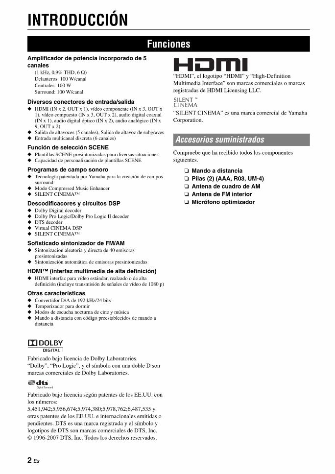
INTRODUCCIÓN
Amplificador de potencia incorporado de 5 canales
(1 kHz, 0,9% THD, 6 Ω)Delanteros: 100 W/canalCentrales: 100 WSurround: 100 W/canal
Diversos conectores de entrada/salida◆ HDMI (IN x 2, OUT x 1), vídeo componente (IN x 3, OUT x
1), vídeo compuesto (IN x 3, OUT x 2), audio digital coaxial (IN x 1), audio digital óptico (IN x 2), audio analógico (IN x 9, OUT x 2)
◆ Salida de altavoces (5 canales), Salida de altavoz de subgraves◆ Entrada multicanal discreta (6 canales)
Función de selección SCENE◆ Plantillas SCENE presintonizadas para diversas situaciones◆ Capacidad de personalización de plantillas SCENE
Programas de campo sonoro◆ Tecnología patentada por Yamaha para la creación de campos
surround◆ Modo Compressed Music Enhancer◆ SILENT CINEMA™
Descodificacores y circuitos DSP◆ Dolby Digital decoder◆ Dolby Pro Logic/Dolby Pro Logic II decoder◆ DTS decoder◆ Virtual CINEMA DSP◆ SILENT CINEMA™
Sofisticado sintonizador de FM/AM◆ Sintonización aleatoria y directa de 40 emisoras
presintonizadas◆ Sintonización automática de emisoras presintonizadas
HDMI™ (interfaz multimedia de alta definición)◆ HDMI interfaz para vídeo estándar, realzado o de alta
definición (incluye transmisión de señales de vídeo de 1080 p)
Otras características◆ Convertidor D/A de 192 kHz/24 bits◆ Temporizador para dormir◆ Modos de escucha nocturna de cine y música◆ Mando a distancia con código preestablecidos de mando a
distancia
Fabricado bajo licencia de Dolby Laboratories.“Dolby”, “Pro Logic”, y el símbolo con una doble D son marcas comerciales de Dolby Laboratories.
Fabricado bajo licencia según patentes de los EE.UU. con los números:5,451,942;5,956,674;5,974,380;5,978,762;6,487,535 y otras patentes de los EE.UU. e internacionales emitidas o pendientes. DTS es una marca registrada y el símbolo y logotipos de DTS son marcas comerciales de DTS, Inc.© 1996-2007 DTS, Inc. Todos los derechos reservados.
“HDMI”, el logotipo “HDMI” y “High-Definition Multimedia Interface” son marcas comerciales o marcas registradas de HDMI Licensing LLC.
“SILENT CINEMA” es una marca comercial de Yamaha Corporation.
Compruebe que ha recibido todos los componentes siguientes.
❏ Mando a distancia❏ Pilas (2) (AAA, R03, UM-4)❏ Antena de cuadro de AM❏ Antena de FM interior❏ Micrófono optimizador
Funciones
Accesorios suministrados
2 Es
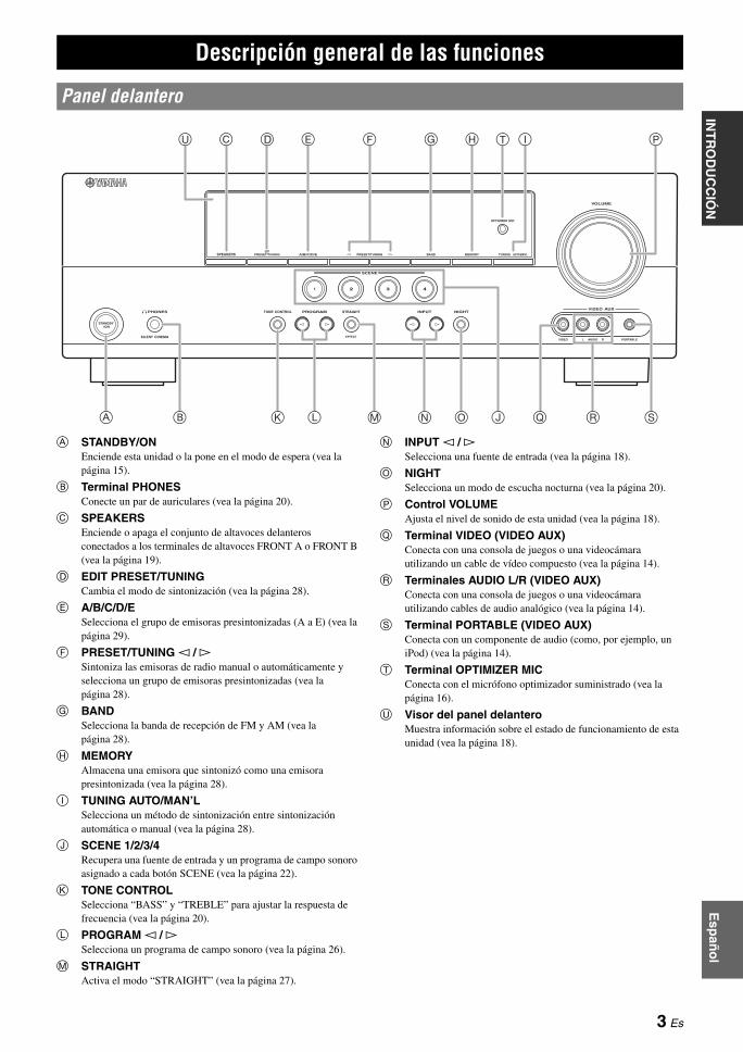
Esp
año
lIN
FO
RM
AC
IÓN
A
DIC
ION
AL
AP
ÉN
DIC
EP
RE
PAR
AC
IÓN
FU
NC
ION
AM
IEN
TO B
ÁS
ICO
FU
NC
ION
AM
IEN
TO A
VAN
ZA
DO
INT
RO
DU
CC
IÓN
A STANDBY/ONEnciende esta unidad o la pone en el modo de espera (vea la página 15).
B Terminal PHONESConecte un par de auriculares (vea la página 20).
C SPEAKERSEnciende o apaga el conjunto de altavoces delanteros conectados a los terminales de altavoces FRONT A o FRONT B (vea la página 19).
D EDIT PRESET/TUNINGCambia el modo de sintonización (vea la página 28).
E A/B/C/D/ESelecciona el grupo de emisoras presintonizadas (A a E) (vea la página 29).
F PRESET/TUNING l / h Sintoniza las emisoras de radio manual o automáticamente y selecciona un grupo de emisoras presintonizadas (vea la página 28).
G BANDSelecciona la banda de recepción de FM y AM (vea la página 28).
H MEMORYAlmacena una emisora que sintonizó como una emisora presintonizada (vea la página 28).
I TUNING AUTO/MAN’LSelecciona un método de sintonización entre sintonización automática o manual (vea la página 28).
J SCENE 1/2/3/4Recupera una fuente de entrada y un programa de campo sonoro asignado a cada botón SCENE (vea la página 22).
K TONE CONTROLSelecciona “BASS” y “TREBLE” para ajustar la respuesta de frecuencia (vea la página 20).
L PROGRAM l / h Selecciona un programa de campo sonoro (vea la página 26).
M STRAIGHTActiva el modo “STRAIGHT” (vea la página 27).
N INPUT l / h Selecciona una fuente de entrada (vea la página 18).
O NIGHTSelecciona un modo de escucha nocturna (vea la página 20).
P Control VOLUMEAjusta el nivel de sonido de esta unidad (vea la página 18).
Q Terminal VIDEO (VIDEO AUX)Conecta con una consola de juegos o una videocámara utilizando un cable de vídeo compuesto (vea la página 14).
R Terminales AUDIO L/R (VIDEO AUX)Conecta con una consola de juegos o una videocámara utilizando cables de audio analógico (vea la página 14).
S Terminal PORTABLE (VIDEO AUX)Conecta con un componente de audio (como, por ejemplo, un iPod) (vea la página 14).
T Terminal OPTIMIZER MICConecta con el micrófono optimizador suministrado (vea la página 16).
U Visor del panel delanteroMuestra información sobre el estado de funcionamiento de esta unidad (vea la página 18).
Descripción general de las funciones
Panel delantero
OPTIMIZER MIC
PHONES
SILENT CINEMA
TONE CONTROL PROGRAM STRAIGHT INPUT
VIDEO AUDIO PORTABLE
VIDEO AUX
VOLUME
EFFECT
l h l h
SCENE
STANDBY/ON
1
NIGHT
2 3 4
SPEAKERS PRESET/TUNINGEDIT
A/B/C/D/E PRESET/TUNINGl h BAND MEMORY TUNING AUTO/MAN'L
A
C D G H T
K OL N
IU PE F
J Q SB RM
3 Es

Descripción general de las funciones
a Indicador de descodificadorSe enciende cuando funciona cualquier descodificador de esta unidad.
b Indicador ENHANCERSe enciende cuando está activado el modo Compressed Music Enhancer (vea la página 26).
c Indicador VIRTUALSe enciende cuando Virtual CINEMA DSP está activo (vea la página 27).
d Indicador SILENT CINEMASe enciende cuando se conectan los auriculares y se selecciona un programa de campo sonoro (vea la página 27).
e Indicadores de fuentes de entrada El cursor correspondiente se enciende para mostrar la fuente de entrada seleccionada.
f Indicador YPAOSe enciende cuando se ejecuta “AUTO SETUP” y cuando se emplean sin ninguna modificación los ajustes de los altavoces establecidos durante el “AUTO SETUP” (vea la página 16).
g Indicadores de sintonizadorSe enciende cuando esta unidad está en el modo de sintonización de FM o AM (vea la página 28).
h Indicador MUTEParpadea cuando está activa la función MUTE (vea la página 20).
i Indicador de nivel VOLUMEIndica el nivel actual del sonido.
j Indicador PCMSe enciende cuando esta unidad está reproduciendo señales de audio digital de PCM (Modulación por codificación de impulsos).
k Indicador de auricularesSe enciende cuando se conectan auriculares (vea la página 20).
l Indicadores SP A BSe encienden de acuerdo con el conjunto de altavoces seleccionado (vea la página 18).
m Indicador NIGHTSe ilumina cuando selecciona un modo de escucha nocturna (vea la página 20).
n Indicador CINEMA DSPSe enciende cuando selecciona un programa de campo sonoro (vea la página 27).
o Pantalla de información múltipleMuestra el nombre del programa de campo sonoro actual y otra información cuando se realizan o se modifican los ajustes.
p Indicador SLEEPSe enciende cuando el temporizador para dormir está activado (vea la página 21).
q Indicadores de canales de entrada y altavoces
• Indicador LFESe enciende cuando la señal de entrada contiene la señal LFE.• Indicadores de canales de entradaIndican los componentes de canales de la señal de entrada digital actual.
Visor del panel delantero
DVR DVD CDV-AUX DTV/CBL MD/CD-R TUNER
ENHANCERSILENT CINEMA
NIGHT
AUTOYPAOPRESET
TUNED
MUTE
VOLUMEMEMORY
SLEEPVIRTUAL
PCM
A BSP
mS
ft
dB
LFEL C RSL SR
dB
STEREO
q PLq PLq DIGITAL
t
a b c d fe g h i
j k l m n o p q
LFEL C RSL SR
Indicador LFE
Indicadores de canales de entrada
4 Es
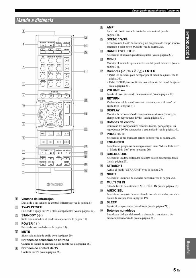
Descripción general de las funcionesE
spañ
ol
INF
OR
MA
CIÓ
N
AD
ICIO
NA
LA
PÉ
ND
ICE
PR
EPA
RA
CIÓ
NF
UN
CIO
NA
MIE
NTO
BÁ
SIC
OF
UN
CIO
NA
MIE
NTO
AVA
NZ
AD
OIN
TR
OD
UC
CIÓ
N
a Ventana de infrarrojosDa salida a las señales de control infrarrojas (vea la página 8).
b TV/AV POWER Enciende o apaga su TV u otros componentes (vea la página 37).
c STANDBY ( ) Sitúe esta unidad en el modo de espera (vea la página 15).
d POWER ( ) Encienda esta unidad (vea la página 15).
e MUTE Silencia la salida de audio (vea la página 20).
f Botones de selección de entradaCambia la fuente de entrada a cada fuente (vea la página 18).
g Botones de control de TVControla su TV (vea la página 36).
h AMP Pulse este botón antes de controlar esta unidad (vea la página 18).
i SCENE 1/2/3/4Recupera una fuente de entrada y un programa de campo sonoro asignado a cada botón SCENE (vea la página 22).
j BAND LEVEL TITLESelecciona el altavoz que desea ajustar (vea la página 20).
k MENUMuestra el menú de ajuste en el visor del panel delantero (vea la página 31).
l Cursores (l / h / n / k) / ENTER• Pulse los cursores para navegar por el menú de ajuste (vea la
página 31).• Pulse ENTER para confirmar una selección del menú de ajuste
(vea la página 31).
m VOLUME +/–Ajusta el nivel de sonido de esta unidad (vea la página 18).
n RETURN Vuelve al nivel de menú anterior cuando aparece el menú de ajuste (vea la página 31).
o DISPLAY Muestra la información de componentes externos (como, por ejemplo, un reproductor DVD) (vea la página 37).
p Botones de controlControlan los componentes externos (como, por ejemplo, un reproductor DVD) conectados a esta unidad (vea la página 37).
q PROG l / h Selecciona el programa de campo sonoro (vea la página 26).
r ENHANCER Establece el programa de campo sonoro en el “Music Enh. 2ch” o “Music Enh. 5ch” (vea la página 26).
s SUR.DECODE Selecciona un descodificador de entre cuatro descodificadores (vea la página 27).
t STRAIGHT Activa el modo “STRAIGHT” (vea la página 27).
u NIGHT Selecciona un modo de escucha nocturna (vea la página 20).
v MULTI CH IN Sitúa la fuente de entrada en MULTI CH IN (vea la página 19).
w AUDIO SELSelecciona un ajuste de selección de entrada de audio para cada fuente de entrada (vea la página 19).
x SLEEPAjusta el temporizador para dormir (vea la página 21).
y Botones numéricosIntroduzca códigos del mando a distancia o un número de emisora presintonizada (vea la página 38).
Mando a distancia
POWER
CD MD/CD-R TUNER
DVD
V-AUX
BAND LEVELTITLE MENU
RETURN
ENTER
REC
PROG ENHANCER SUR.DECODE
STRAIGHT NIGHT
MULTI CH IN AUDIO SEL SLEEPENT
DISPLAY
VOLUME
AMP
DTV/CBL DVR TV CH
TV VOLTV INPUT TV MUTE
POWER POWER
MUTE
STANDBY
TV
A B
AV
C
D E
SCENE
1 2
2 3 41
6
0
7
10
85
9
3 4
PRESET/CH
A/B
/C/D
/E
PRESET/CH
A/B
/C/D
/E
y
c
k
r
u
o
d
e
s
x
g
m
a
b
i
q
p
h
j
n
t
v
f
l
w
5 Es
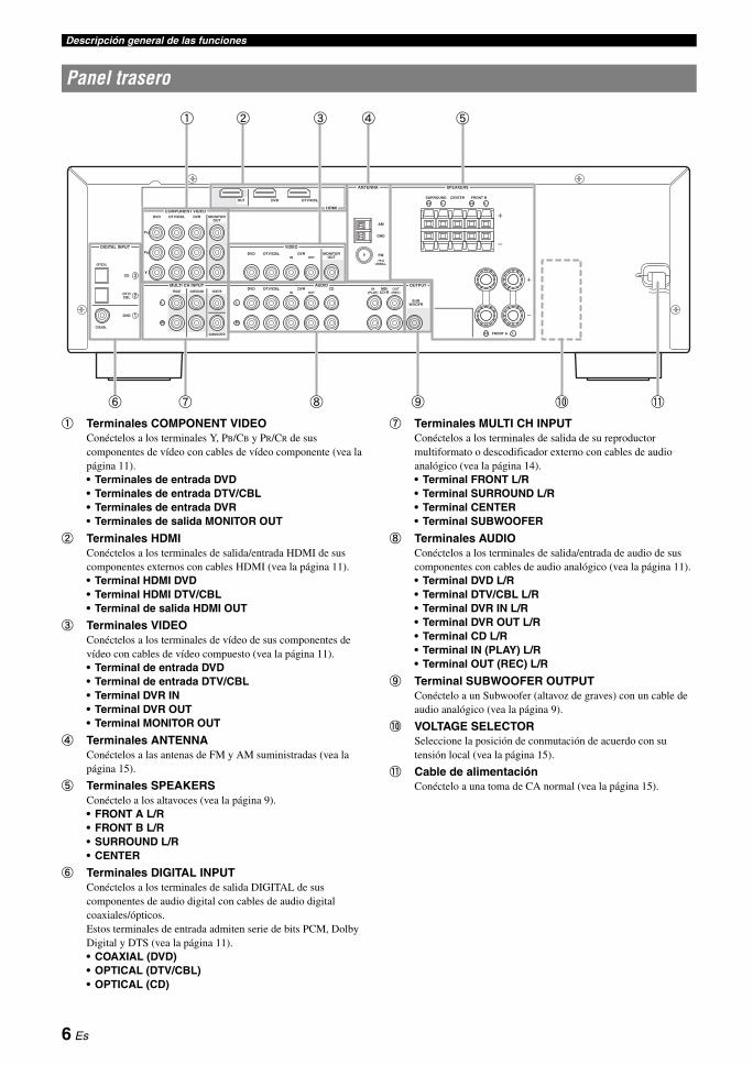
Descripción general de las funciones
a Terminales COMPONENT VIDEOConéctelos a los terminales Y, PB/CB y PR/CR de sus componentes de vídeo con cables de vídeo componente (vea la página 11).• Terminales de entrada DVD• Terminales de entrada DTV/CBL• Terminales de entrada DVR• Terminales de salida MONITOR OUT
b Terminales HDMIConéctelos a los terminales de salida/entrada HDMI de sus componentes externos con cables HDMI (vea la página 11).• Terminal HDMI DVD• Terminal HDMI DTV/CBL• Terminal de salida HDMI OUT
c Terminales VIDEOConéctelos a los terminales de vídeo de sus componentes de vídeo con cables de vídeo compuesto (vea la página 11).• Terminal de entrada DVD• Terminal de entrada DTV/CBL• Terminal DVR IN• Terminal DVR OUT• Terminal MONITOR OUT
d Terminales ANTENNAConéctelos a las antenas de FM y AM suministradas (vea la página 15).
e Terminales SPEAKERSConéctelo a los altavoces (vea la página 9).• FRONT A L/R• FRONT B L/R• SURROUND L/R• CENTER
f Terminales DIGITAL INPUTConéctelos a los terminales de salida DIGITAL de sus componentes de audio digital con cables de audio digital coaxiales/ópticos. Estos terminales de entrada admiten serie de bits PCM, Dolby Digital y DTS (vea la página 11).• COAXIAL (DVD)• OPTICAL (DTV/CBL)• OPTICAL (CD)
g Terminales MULTI CH INPUTConéctelos a los terminales de salida de su reproductor multiformato o descodificador externo con cables de audio analógico (vea la página 14).• Terminal FRONT L/R• Terminal SURROUND L/R• Terminal CENTER• Terminal SUBWOOFER
h Terminales AUDIOConéctelos a los terminales de salida/entrada de audio de sus componentes con cables de audio analógico (vea la página 11).• Terminal DVD L/R• Terminal DTV/CBL L/R• Terminal DVR IN L/R• Terminal DVR OUT L/R• Terminal CD L/R• Terminal IN (PLAY) L/R • Terminal OUT (REC) L/R
i Terminal SUBWOOFER OUTPUTConéctelo a un Subwoofer (altavoz de graves) con un cable de audio analógico (vea la página 9).
j VOLTAGE SELECTORSeleccione la posición de conmutación de acuerdo con su tensión local (vea la página 15).
k Cable de alimentaciónConéctelo a una toma de CA normal (vea la página 15).
Panel trasero
DIGITAL INPUT
COMPONENT VIDEO
VIDEO
AUDIOMULTI CH INPUT
HDMI
ANTENNA SPEAKERS
DVD
OPTICAL
DVDSURROUND CENTER FRONT B
FRONT A
DVR
SURROUNDFRONT CENTER
SUBWOOFER
DTV/CBL
DVD DVR FM
AM
GND
IN OUTDTV/CBL
DVD DVR CDOUTPUT
SUBWOOFR
IN OUTMD/
CD-RIN
(PLAY)OUT
(REC)DTV/CBL
DTV/CBL
MONITOROUT
MONITOROUT
CD
PR
PB
Y
DVD
COAXIAL
DTV/CBL
OUT
UNBAL.
f g h i
d eb ca
j k
6 Es
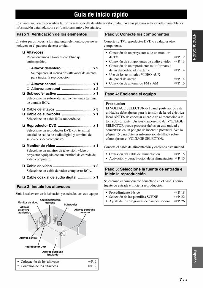
Esp
año
lIN
FO
RM
AC
IÓN
A
DIC
ION
AL
AP
ÉN
DIC
EP
RE
PAR
AC
IÓN
FU
NC
ION
AM
IEN
TO B
ÁS
ICO
FU
NC
ION
AM
IEN
TO A
VAN
ZA
DO
INT
RO
DU
CC
IÓN
Los pasos siguientes describen la forma más sencilla de utilizar esta unidad. Vea las páginas relacionadas para obtener información detallada sobre el funcionamiento y los ajustes.
En estos pasos necesita los siguientes elementos, que no se incluyen en el paquete de esta unidad.
❏ AltavocesRecomendamos altavoces con blindaje antimagnético.
❏ Altavoz delantero ............................... x 2Se requieren al menos dos altavoces delanteros para iniciar la reproducción.
❏ Altavoz central ................................... x 1❏ Altavoz surround ............................... x 2
❏ Subwoofer activo .................................... x 1Seleccione un subwoofer activo que tenga terminal de entrada RCA.
❏ Cable de altavoz ..................................... x 5❏ Cable de subwoofer ............................... x 1
Seleccione un cable RCA monofónico.
❏ Reproductor DVD ................................... x 1Seleccione un reproductor DVD con terminal coaxial de salida de audio digital y terminal de salida de vídeo compuesto.
❏ Monitor de vídeo ..................................... x 1Seleccione un monitor de televisión, vídeo o proyector equipado con un terminal de entrada de vídeo compuesto.
❏ Cable de vídeo ........................................ x 2Seleccione un cable de vídeo compuesto RCA.
❏ Cable coaxial de audio digital ............... x 1
Sitúe los altavoces en la habitación y conéctelos con este equipo.
Conecte su TV, reproductor DVD o cualquier otro componente.
Conecte el cable de alimentación y encienda esta unidad.
Seleccione el componente conectado en el paso 3 como fuente de entrada e inicie la reproducción.
Guía de inicio rápido
Paso 1: Verificación de los elementos
Paso 2: Instale los altavoces
• Colocación de los altavoces ☞P. 9• Conexión de los altavoces ☞P. 9
Monitor de vídeo
Altavozdelanteroizquierdo
Altavoz central
Reproductor DVD
Altavoz surround izquierdo
Altavoz surround derecho
Subwoofer
Altavoz delantero derecho
Paso 3: Conecte los componentes
• Conexión de un proyector o de un monitor de TV ☞P. 12
• Conexión de componentes de audio y vídeo ☞P. 13• Conexión de un reproductor multiformato o
de un descodificador externo ☞P. 14• Uso de los terminales VIDEO AUX
del panel delantero ☞P. 14• Conexión de antenas de FM y AM ☞P. 15
Paso 4: Encienda el equipo
PrecauciónEl VOLTAGE SELECTOR del panel posterior de esta unidad se debe ajustar para la tensión de la red eléctrica local ANTES de conectar el cable de alimentación a la toma de corriente. Un ajuste incorrecto del VOLTAGE SELECTOR puede provocar daños en esta unidad y convertirse en un peligro de incendio potencial. Vea la página 15 para obtener información detallada sobre cómo ajustar el VOLTAGE SELECTOR.
• Conexión del cable de alimentación ☞P. 15• Activación y desactivación de la alimentación ☞P. 15
Paso 5: Seleccione la fuente de entrada e inicie la reproducción
• Procedimiento básico ☞P. 18• Selección de las plantillas SCENE ☞P. 22• Ajuste de los programas de campos sonoro ☞P. 26
7 Es

PREPARACIÓN
1 Retire la tapa del compartimento de las pilas.
2 Introduzca las cuatro pilas suministradas (AAA, R03, UM-4) según las marcas de polaridad (+ y –) en el interior del compartimento de las pilas.
3 Cierre la tapa del compartimento de las pilas.
Notas• Cambie las pilas si observa alguna de las siguientes condiciones:
– el margen de control del mando a distancia se reduce.• No utilice conjuntamente pilas viejas y pilas nuevas.• No utilice conjuntamente pilas de diferentes tipos (por ejemplo,
alcalinas y de manganeso). Lea con atención las indicaciones de las pilas porque hay tipos diferentes que pueden tener la misma forma y color.
• Tire las pilas inmediatamente si tienen pérdidas. Evite tocar el material que sale de las pilas o dejar que éste entre en contacto con ropas, etc. Limpie a fondo el compartimento de las pilas antes de instalar otras nuevas.
• No tire las pilas con la basura doméstica; deshágase de ellas según la reglamentación local.
• Si el mando a distancia se queda sin pilas durante más de 2 minutos, o si las pilas agotadas se quedan en su interior, el contenido de la memoria podría borrarse. Cuando se borre la memoria, introduzca pilas nuevas y ajuste el código del mando a distancia.
El mando a distancia transmite un rayo infrarrojo direccional.Asegúrese de apuntar directamente el mando a distancia al sensor de mando a distancia de esta unidad durante el funcionamiento.
a Ventana de infrarrojosDa salida a las señales de control infrarrojas. Apunte esta ventana al componente que quiera controlar.
y• Para configurar los códigos del mando a distancia para otros
componentes, vea la página 38.
Notas• No derrame agua u otros líquidos en el mando a distancia.• No deje caer el mando a distancia.• No deje ni guarde el mando a distancia en las condiciones siguientes:
– lugares de humedad alta como, por ejemplo, cerca de un baño– lugares con temperaturas elevadas, por ejemplo, cerca de una
calefacción o estufa– lugares con temperaturas muy bajas– lugares polvorientos
• Para configurar los códigos del mando a distancia para otros componentes, vea la página 38.
Preparación del mando a distancia
Instalación de las pilas en el mando a distancia
1 3
2
Utilización del mando a distancia
30º 30º Aproximadamente 6 m
8 Es
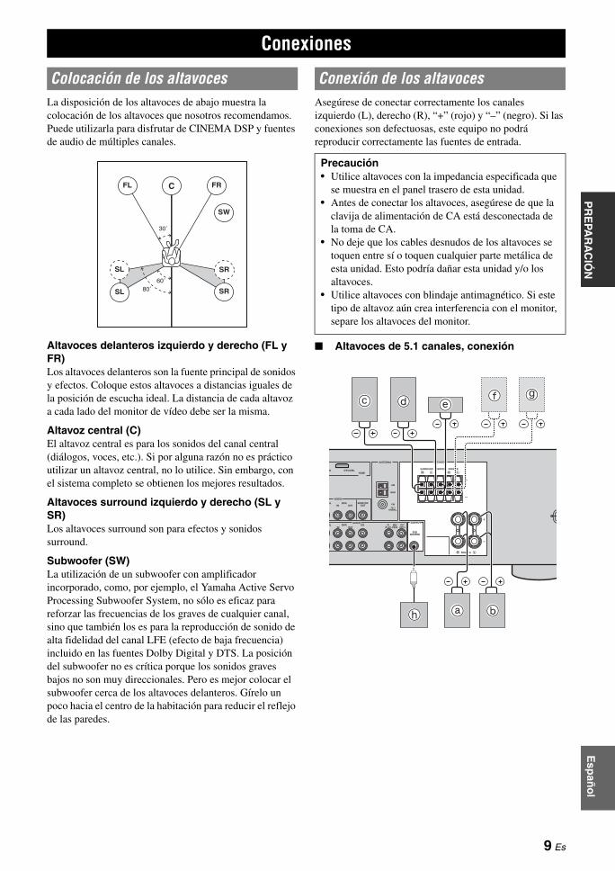
Esp
año
lIN
TR
OD
UC
CIÓ
NIN
FO
RM
AC
IÓN
A
DIC
ION
AL
AP
ÉN
DIC
EF
UN
CIO
NA
MIE
NTO
BÁ
SIC
OF
UN
CIO
NA
MIE
NTO
AVA
NZ
AD
OP
RE
PAR
AC
IÓN
La disposición de los altavoces de abajo muestra la colocación de los altavoces que nosotros recomendamos. Puede utilizarla para disfrutar de CINEMA DSP y fuentes de audio de múltiples canales.
Altavoces delanteros izquierdo y derecho (FL y FR)Los altavoces delanteros son la fuente principal de sonidos y efectos. Coloque estos altavoces a distancias iguales de la posición de escucha ideal. La distancia de cada altavoz a cada lado del monitor de vídeo debe ser la misma.
Altavoz central (C)El altavoz central es para los sonidos del canal central (diálogos, voces, etc.). Si por alguna razón no es práctico utilizar un altavoz central, no lo utilice. Sin embargo, con el sistema completo se obtienen los mejores resultados.
Altavoces surround izquierdo y derecho (SL y SR)Los altavoces surround son para efectos y sonidos surround.
Subwoofer (SW)La utilización de un subwoofer con amplificador incorporado, como, por ejemplo, el Yamaha Active Servo Processing Subwoofer System, no sólo es eficaz para reforzar las frecuencias de los graves de cualquier canal, sino que también los es para la reproducción de sonido de alta fidelidad del canal LFE (efecto de baja frecuencia) incluido en las fuentes Dolby Digital y DTS. La posición del subwoofer no es crítica porque los sonidos graves bajos no son muy direccionales. Pero es mejor colocar el subwoofer cerca de los altavoces delanteros. Gírelo un poco hacia el centro de la habitación para reducir el reflejo de las paredes.
Asegúrese de conectar correctamente los canales izquierdo (L), derecho (R), “+” (rojo) y “–” (negro). Si las conexiones son defectuosas, este equipo no podrá reproducir correctamente las fuentes de entrada.
■ Altavoces de 5.1 canales, conexión
Conexiones
Colocación de los altavoces
60˚
30˚
FL FRC
SL
SR
SR80˚
SL
SW
Conexión de los altavoces
Precaución• Utilice altavoces con la impedancia especificada que
se muestra en el panel trasero de esta unidad.• Antes de conectar los altavoces, asegúrese de que la
clavija de alimentación de CA está desconectada de la toma de CA.
• No deje que los cables desnudos de los altavoces se toquen entre sí o toquen cualquier parte metálica de esta unidad. Esto podría dañar esta unidad y/o los altavoces.
• Utilice altavoces con blindaje antimagnético. Si este tipo de altavoz aún crea interferencia con el monitor, separe los altavoces del monitor.
LRLR
LR
HDMI
VIDEO
AUDIO OUTPUT
ANTENNA SPEAKERS
BL
D DTV/CBLSURROUND CENTER FRONT B
FRONT A
MONITOR OUT
MD/ CD-R
SUB WOOFER
OUT (REC)
IN (PLAY)
DVR
BL DVR CD
IN OUT
IN OUT
AM
GND
FM
75 UNBAL.
a b
c df g
e
h
9 Es

Conexiones
* Puede seleccionar el conjunto de altavoces delanteros de Altavoces delanteros (A) y Altavoces delanteros (B) pulsando repetidamente CSPEAKERS. Vea la página 19 para obtener información detallada.
■ Conecte los cables de cada altavoz
Los cables son de color o forma diferente, tal vez con una franja, ranura o resalto. Conecte el cable con franjas (ranurado, etc.) a los terminales “+” (rojos) de su altavoz. Conecte el cable normal a los terminales “–” (negros).
■ Antes de conectar al terminal SPEAKERSUn cable de altavoz consiste realmente en un par de cables aislados uno junto al otro.
Quite aproximadamente 10 mm de aislamiento del extremo de cada cable de altavoz y luego retuerza juntos los hilos expuestos del cable para evitar cortocircuitos.
■ Conexión a los terminales FRONT A
1 Afloje la perilla.
2 Inserte el extremo expuesto del cable del altavoz en la hendidura del terminal.
3 Apriete la perilla para asegurar el cable.
■ Conexión a los terminales FRONT B, CENTER y SURROUND
1 Apriete la lengüeta hacia abajo.
2 Inserte el extremo expuesto del cable del altavoz en el orificio del terminal.
3 Suelte la lengüeta para asegurar el cable.
AltavocesTerminales de esta
unidad
a Altavoz delantero (A) Derecho*
FRONT A (R)
b Altavoz delantero (A) Izquierdo*
FRONT A (L)
c Altavoz surround Derecho
SURROUND (R)
d Altavoz surround Izquierdo
SURROUND (L)
e Altavoz central CENTER
f Altavoz delantero (B) Derecho*
FRONT B (R)
g Altavoz delantero (B) Izquierdo*
FRONT B (L)
h Subwoofer SUBWOOFER
10 mm
12
3
Rojo: positivo (+)
Negro: negativo (–)
Rojo: positivo (+)
Negro: negativo (–)
10 Es

ConexionesE
spañ
ol
INT
RO
DU
CC
IÓN
INF
OR
MA
CIÓ
N
AD
ICIO
NA
LA
PÉ
ND
ICE
FU
NC
ION
AM
IEN
TO B
ÁS
ICO
FU
NC
ION
AM
IEN
TO A
VAN
ZA
DO
PR
EPA
RA
CIÓ
N
Terminales de audio y clavijas de cables
Terminales AUDIOPara señales de audio analógico convencional transmitido por cables de audio analógico izquierdo y derecho. Conecte las clavijas rojas a los terminales derechos y las blancos a los izquierdos.
Terminal COAXIALPara señales de audio digital transmitidas por cable de audio digital coaxial.
Terminales OPTICALPara señales de audio digital transmitidas por cables de audio digital ópticos.
Notas• Puede utilizar los terminales digitales para introducir series de bits PCM,
Dolby Digital y DTS. Todos los terminales de entrada digital son compatibles con señales digitales de frecuencia de muestreo de hasta 96 kHz.
• Esta unidad se ocupa de las señales digitales y analógicas de forma independiente. Así, las señales de audio introducidas en los terminales digitales no salen en el terminal AUDIO OUT (REC) analógico.
Terminales de vídeo y clavijas de cables
Terminales VIDEOPara señales de vídeo compuesto convencional transmitidas por cables de vídeo compuesto.
Terminales COMPONENT VIDEOPara señales de componente, separadas en señales de vídeo de luminancia (Y) y crominancia (PB, PR) y transmitidas por conductores separados de cables de vídeo componente.
Puede reproducir imágenes conectando su monitor de vídeo y componente de fuente de vídeo a esta unidad utilizando conexiones HDMI.En ese momento, las señales de audio/vídeo que salen del componente conectado (como, por ejemplo, un reproductor DVD, etc.) salen al monitor de vídeo conectado solamente cuando se enciende esta unidad y se establece en la fuente de entrada (DVD o DTV/CBL).Además, las señales de audio/vídeo disponibles dependen de la especificación del monitor de vídeo conectado. Consulte el manual de instrucciones de cada componente conectado.
■ Terminal y clavija de cable HDMI
y• Recomendamos utilizar un cable HDMI de una longitud inferior a 5
metros con el logotipo HDMI impreso en él.• Use un cable de conversión (terminal HDMI ↔ terminal DVI-D) para
conectar este equipo a otros componentes DVI.
Puede grabar la señal de audio que sale por el terminal AUDIO OUT (REC) utilizando los componentes de grabación.
Nota• Verifique las leyes de copyright de su país para grabar CDs, programas
de radio, etc. La grabación de materiales protegidos por copyright puede infringir esas leyes.
Conexión de componentes de vídeo
Información sobre terminales y clavijas de cables
COAXIAL
DIGITAL AUDIOAUDIO
OPTICAL
DIGITAL AUDIORL
CORL
(Blanco) (Rojo) (Anaranjado)
Clavijas izquierda y derecha de
cables de audio analógico
Clavija de cable de audio digital
coaxial
Clavija de cable de audio digital
óptico
VIDEOCOMPONENT VIDEO
Y PB PR
PBY PRV
(Amarillo) (Azul) (Rojo)(Verde)
Clavija de cable de vídeo
compuesto
Clavijas de cable de vídeo componente
Información sobre HDMI™
Las señales de audio introducidas en el terminal HDMI no salen de ningún terminal de altavoz, sino que salen del monitor de vídeo conectado. Para disfrutar del sonido de los altavoces conectados a esta unidad,
– realice una conexión analógica o digital además de la conexión HDMI (vea la página 13).
– silencie el volumen del monitor de vídeo conectado.
Uso del terminal AUDIO OUT REC
PR
PB
Y
PR
PB
Y
COMPONENTVIDEO
VIDEO
Flujo de señales de vídeo para MONITOR OUT
EntradaSalida
(MONITOR OUT)
HDMI
Clavija de cable HDMI
11 Es
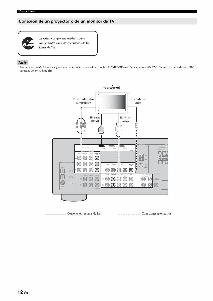
Conexiones
Nota• La conexión podría fallar si apaga el monitor de vídeo conectado al terminal HDMI OUT a través de una conexión DVI. En este caso, el indicador HDMI
parpadea de forma irregular.
Conexión de un proyector o de un monitor de TV
Asegúrese de que esta unidad y otros
componentes estén desenchufados de las
tomas de CA.
LR
L
R
VIDEO
MULTI CH INPUT
DIGITAL INPUT
OUTPUT
ANTENNA SPE
1
2
3
DVD
DVD
COAXIAL
OPTICAL
CD
DTV/CBL
DTV/ CBL
SURROUND CE
MONITOR OUT
SUB WOOFER
DVR
FRONT CENTER
SUBWOOFER
SURROUND
IN OUT
AM
GND
FM
75 UNBAL.
HDMI
DVDOUT DTV/CBL
COMPONENT VIDEODVD DTV/CBL DVR MONITOR
OUT
Y
PR
PB
VPRPBY
LR
MD/ CD-R
OUT (REC)
IN (PLAY)
L
R
AUDIODVD DTV/CBL DVR CD
IN OUT
TV (o proyector)
Entrada de vídeo componente
Entrada de vídeo
Salida de audio
Entrada HDMI
Conexiones recomendadas Conexiones alternativas
12 Es
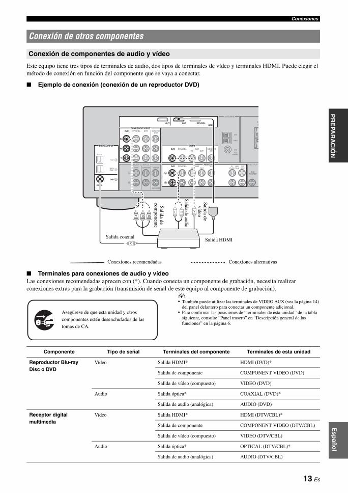
ConexionesE
spañ
ol
INT
RO
DU
CC
IÓN
INF
OR
MA
CIÓ
N
AD
ICIO
NA
LA
PÉ
ND
ICE
FU
NC
ION
AM
IEN
TO B
ÁS
ICO
FU
NC
ION
AM
IEN
TO A
VAN
ZA
DO
PR
EPA
RA
CIÓ
N
Este equipo tiene tres tipos de terminales de audio, dos tipos de terminales de vídeo y terminales HDMI. Puede elegir el método de conexión en función del componente que se vaya a conectar.
■ Ejemplo de conexión (conexión de un reproductor DVD)
■ Terminales para conexiones de audio y vídeoLas conexiones recomendadas aprecen con (*). Cuando conecta un componente de grabación, necesita realizar conexiones extras para la grabación (transmisión de señal de este equipo al componente de grabación).
y• También puede utilizar las terminales de VIDEO AUX (vea la página 14)
del panel delantero para conectar un componente adicional.• Para confirmar las posiciones de “terminales de esta unidad” de la tabla
siguiente, consulte “Panel trasero” en “Descripción general de las funciones” en la página 6.
Conexión de otros componentes
Conexión de componentes de audio y vídeo
R
L
R
L
R
COMPONENT VIDEO
HDMI
VIDEO
AUDIOMULTI CH INPUT
DIGITAL INPUT
OUTPUT
ANTENNA
1
2
3
DVD DTV/CBL DVR
DVD
DVD
COAXIAL
OPTICAL
CD
DTV/CBL
DTV/ CBL
DVDOUT DTV/CBLSU
MONITOR OUT
MD/ CD-R
SUB WOOFER
OUT (REC)
IN (PLAY)
DVR
DVDFRONT CENTER
SUBWOOFER
SURROUNDDTV/CBL DVR CD
IN OUT
IN OUT
MONITOR OUT
AM
GND
FM
75 UNBAL.
Y
PR
PB
PRPBYL R
C
V
Salida de com
ponente
Salida de audio
Salida de vídeo
Salida coaxialSalida HDMI
Conexiones recomendadas Conexiones alternativas
Asegúrese de que esta unidad y otros
componentes estén desenchufados de las
tomas de CA.
Componente Tipo de señal Terminales del componente Terminales de esta unidad
Reproductor Blu-ray Disc o DVD
Vídeo Salida HDMI* HDMI (DVD)*
Salida de componente COMPONENT VIDEO (DVD)
Salida de vídeo (compuesto) VIDEO (DVD)
Audio Salida óptica* COAXIAL (DVD)*
Salida de audio (analógica) AUDIO (DVD)
Receptor digital multimedia
Vídeo Salida HDMI* HDMI (DTV/CBL)*
Salida de componente COMPONENT VIDEO (DTV/CBL)
Salida de vídeo (compuesto) VIDEO (DTV/CBL)
Audio Salida óptica* OPTICAL (DTV/CBL)*
Salida de audio (analógica) AUDIO (DTV/CBL)
13 Es
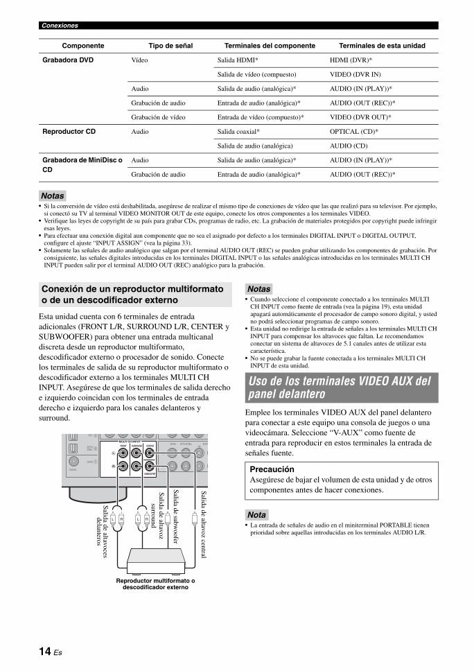
Conexiones
Notas• Si la conversión de vídeo está deshabilitada, asegúrese de realizar el mismo tipo de conexiones de vídeo que las que realizó para su televisor. Por ejemplo,
si conectó su TV al terminal VIDEO MONITOR OUT de este equipo, conecte los otros componentes a los terminales VIDEO.• Verifique las leyes de copyright de su país para grabar CDs, programas de radio, etc. La grabación de materiales protegidos por copyright puede infringir
esas leyes.• Para efectuar una conexión digital aun componente que no sea el asignado por defecto a los terminales DIGITAL INPUT o DIGITAL OUTPUT,
configure el ajuste “INPUT ASSIGN” (vea la página 33).• Solamente las señales de audio analógico que salgan por el terminal AUDIO OUT (REC) se pueden grabar utilizando los componentes de grabación. Por
consiguiente, las señales digitales introducidas en los terminales DIGITAL INPUT o las señales analógicas introducidas en los terminales MULTI CH INPUT pueden salir por el terminal AUDIO OUT (REC) analógico para la grabación.
Esta unidad cuenta con 6 terminales de entrada adicionales (FRONT L/R, SURROUND L/R, CENTER y SUBWOOFER) para obtener una entrada multicanal discreta desde un reproductor multiformato, descodificador externo o procesador de sonido. Conecte los terminales de salida de su reproductor multiformato o descodificador externo a los terminales MULTI CH INPUT. Asegúrese de que los terminales de salida derecho e izquierdo coincidan con los terminales de entrada derecho e izquierdo para los canales delanteros y surround.
Notas• Cuando seleccione el componente conectado a los terminales MULTI
CH INPUT como fuente de entrada (vea la página 19), esta unidad apagará automáticamente el procesador de campo sonoro digital, y usted no podrá seleccionar programas de campo sonoro.
• Esta unidad no redirige la entrada de señales a los terminales MULTI CH INPUT para compensar los altavoces que faltan. Le recomendamos conectar un sistema de altavoces de 5.1 canales antes de utilizar esta característica.
• No se puede grabar la fuente conectada a los terminales MULTI CH INPUT de esta unidad.
Emplee los terminales VIDEO AUX del panel delantero para conectar a este equipo una consola de juegos o una videocámara. Seleccione “V-AUX” como fuente de entrada para reproducir en estos terminales la entrada de señales fuente.
Nota• La entrada de señales de audio en el miniterminal PORTABLE tienen
prioridad sobre aquellas introducidas en los terminales AUDIO L/R.
Grabadora DVD Vídeo Salida HDMI* HDMI (DVR)*
Salida de vídeo (compuesto) VIDEO (DVR IN)
Audio Salida de audio (analógica)* AUDIO (IN (PLAY))*
Grabación de audio Entrada de audio (analógica)* AUDIO (OUT (REC))*
Grabación de vídeo Entrada de vídeo (compuesto)* VIDEO (DVR OUT)*
Reproductor CD Audio Salida coaxial* OPTICAL (CD)*
Salida de audio (analógica) AUDIO (CD)
Grabadora de MiniDisc o CD
Audio Salida de audio (analógica)* AUDIO (IN (PLAY))*
Grabación de audio Entrada de audio (analógica)* AUDIO (OUT (REC))*
Componente Tipo de señal Terminales del componente Terminales de esta unidad
Conexión de un reproductor multiformato o de un descodificador externo
L
R
L
R
MULTI CH INPUT
1
2
3
DVD
COAXIAL
CD
DTV/ CBL
DVDFRONT CENTER
SUBWOOFER
SURROUNDDTV/CBL DVR
IN
L R L R
Salida de altavoces delanteros
Salida de altavoz
surround
Salida de subwoofer
Salida de altavoz central
Reproductor multiformato o descodificador externo
Uso de los terminales VIDEO AUX del panel delantero
PrecauciónAsegúrese de bajar el volumen de esta unidad y de otros componentes antes de hacer conexiones.
14 Es

ConexionesE
spañ
ol
INT
RO
DU
CC
IÓN
INF
OR
MA
CIÓ
N
AD
ICIO
NA
LA
PÉ
ND
ICE
FU
NC
ION
AM
IEN
TO B
ÁS
ICO
FU
NC
ION
AM
IEN
TO A
VAN
ZA
DO
PR
EPA
RA
CIÓ
N
Con esta unidad se suministran antenas interiores de FM y AM. Generalmente, estas antenas deben proporcionar señales de intensidad suficiente. Conecte correctamente cada antena a los terminales designados.
Notas• La antena de cuadro de AM deberá colocarse lejos de esta unidad.• Una antena exterior bien conectada proporciona una recepción más clara
que una interior. Si tiene problemas con la recepción, instale una antena exterior. Consulte al centro de servicio o concesionario Yamaha autorizado acerca de las antena exteriores.
• La antena de cuadro de AM deberá estar siempre conectada, aunque esté conectada una antena AM exterior.
Conexión del cable de la antena de cuadro de AM
Montaje de la antena de cuadro de AM suministrada
Nota• Los tipos de la antena de cuadro de AM suministrados son diferentes
dependiendo de los modelos.
Seleccione la posición de conmutación (superior o inferior) según su tensión local utilizando un destornillador de punta plana.Las tensiones son 110-120/220-240 V CA, 50/60 Hz.
Cuando todas las conexiones estén completas, enchufe el cable de alimentación a la toma de CA.
Pulse ASTANDBY/ON (o dPOWER) para encender esta unidad.
y• Cuando encienda esta unidad habrá un retardo de 4 a 5 segundos hasta
que esta unidad pueda reproducir sonidos.
Pulse ASTANDBY/ON (o cSTANDBY) para apagar esta unidad.
Nota• En el modo de espera, esta unidad consume un poco de energía para
recibir señales infrarrojas del mando a distancia.
Conexión de antenas de FM y AM
DEO
ANTENNA
R SURRO
AUDIO OUTPDVR CD
S
N OUT
DVR
AM
GND
FM
UNBAL.75
N OUT MONITOR OUT
MD/CD-R
OUT (REC)
IN (PLAY)
Antena de AM exteriorUtilice un cable cubierto de vinilo de 5 a 10 m extendido hacia el exterior desde una ventana.
Antena de cuadro de AM (suministrada)
Antena de FM interior (suministrada)
TierraPara tener la máxima seguridad y las mínimas interferencias, conecte el terminal GND de la antena con una buena conexión a tierra. Una buena conexión a tierra es una varilla metálica clavada en tierra húmeda.
Abra la palanca
Inserte Cierre la palanca
Conexión del cable de alimentación
VOLTAGE SELECTOR (únicamente modelos de Asia y General)
PrecauciónEl VOLTAGE SELECTOR del panel posterior de esta unidad se debe ajustar para la tensión de la red eléctrica local ANTES de conectar el cable de alimentación a la toma de corriente.Un ajuste incorrecto del VOLTAGE SELECTOR puede provocar daños en el equipo y convertirse en un peligro de incendio potencial.
Conexión del cable de alimentación de CA
Activación y desactivación de la alimentación
Encendido de esta unidad
Sitúe esta unidad en el modo de espera
110V- 120V
220V- 240V
VOLTAGESELECTOR
15 Es
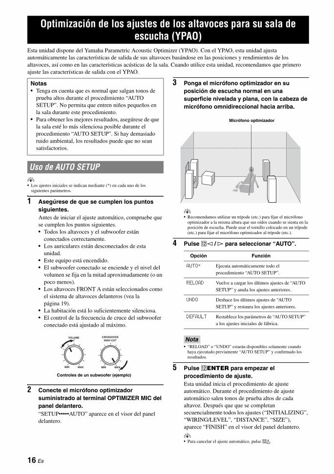
Esta unidad dispone del Yamaha Parametric Acoustic Optimizer (YPAO). Con el YPAO, esta unidad ajusta automáticamente las características de salida de sus altavoces basándose en las posiciones y rendimientos de los altavoces, así como en las características acústicas de la sala. Cuando utilice esta unidad, recomendamos que primero ajuste las características de salida con el YPAO.
y• Los ajustes iniciales se indican mediante (*) en cada uno de los
siguientes parámetros.
1 Asegúrese de que se cumplen los puntos siguientes.Antes de iniciar el ajuste automático, compruebe que se cumplen los puntos siguientes.• Todos los altavoces y el subwoofer están
conectados correctamente.• Los auriculares están desconectados de esta
unidad.• Este equipo está encendido.• El subwoofer conectado se enciende y el nivel del
volumen se fija en la mitad aproximadamente (o un poco menos).
• Los altavoces FRONT A están seleccionados como el sistema de altavoces delanteros (vea la página 19).
• La habitación está lo suficientemente silenciosa.• El control de la frecuencia de cruce del subwoofer
conectado está ajustado al máximo.
2 Conecte el micrófono optimizador suministrado al terminal OPTIMIZER MIC del panel delantero.“SETUP•••••AUTO” aparece en el visor del panel delantero.
3 Ponga el micrófono optimizador en su posición de escucha normal en una superficie nivelada y plana, con la cabeza de micrófono omnidireccional hacia arriba.
y• Recomendamos utilizar un trípode (etc.) para fijar el micrófono
optimizador a la misma altura que sus oídos cuando se sienta en la posición de escucha. Puede usar el tornillo colocado en un trípode (etc.) para fijar el micrófono optimizador al trípode (etc.).
4 Pulse ll / h para seleccionar “AUTO”.
Nota• “RELOAD” o “UNDO” estarán disponibles solamente cuando
haya ejecutado previamente “AUTO SETUP” y confirmado los resultados.
5 Pulse lENTER para empezar el procedimiento de ajuste.Esta unidad inicia el procedimiento de ajuste automático. Durante el procedimiento de ajuste automático salen tonos de prueba altos de cada altavoz. Después que que se completan secuencialmente todos los ajustes (“INITIALIZING”, “WIRING/LEVEL”, “DISTANCE”, “SIZE”), aparece “FINISH” en el visor del panel delantero.
y• Para cancelar el ajuste automático, pulse lk.
Optimización de los ajustes de los altavoces para su sala de escucha (YPAO)
Notas• Tenga en cuenta que es normal que salgan tonos de
prueba altos durante el procedimiento “AUTO SETUP”. No permita que entren niños pequeños en la sala durante este procedimiento.
• Para obtener los mejores resultados, asegúrese de que la sala esté lo más silenciosa posible durante el procedimiento “AUTO SETUP”. Si hay demasiado ruido ambiental, los resultados puede que no sean satisfactorios.
Uso de AUTO SETUP
VOLUME
MIN MAX MIN MAX
CROSSOVER HIGH CUT
Controles de un subwoofer (ejemplo)
Opción Función
AUTO* Ejecuta automáticamente todo el
procedimiento “AUTO SETUP”.
RELOAD Vuelve a cargar los últimos ajustes de “AUTO
SETUP” y anula los ajustes anteriores.
UNDO Deshace los últimos ajustes de “AUTO
SETUP” y restaura los ajustes anteriores.
DEFAULT Restablece los parámetros de “AUTO SETUP”
a los ajustes iniciales de fábrica.
Micrófono optimizador
16 Es
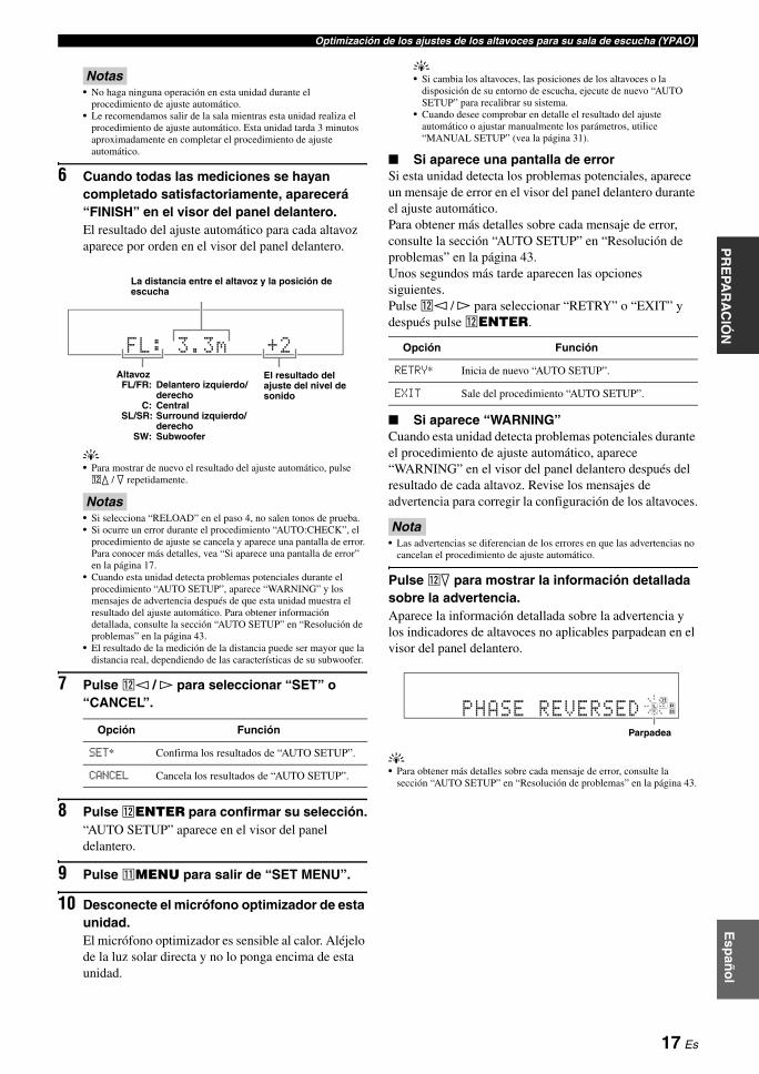
Optimización de los ajustes de los altavoces para su sala de escucha (YPAO)E
spañ
ol
INT
RO
DU
CC
IÓN
INF
OR
MA
CIÓ
N
AD
ICIO
NA
LA
PÉ
ND
ICE
FU
NC
ION
AM
IEN
TO B
ÁS
ICO
FU
NC
ION
AM
IEN
TO A
VAN
ZA
DO
PR
EPA
RA
CIÓ
N
Notas• No haga ninguna operación en esta unidad durante el
procedimiento de ajuste automático.• Le recomendamos salir de la sala mientras esta unidad realiza el
procedimiento de ajuste automático. Esta unidad tarda 3 minutos aproximadamente en completar el procedimiento de ajuste automático.
6 Cuando todas las mediciones se hayan completado satisfactoriamente, aparecerá “FINISH” en el visor del panel delantero.El resultado del ajuste automático para cada altavoz aparece por orden en el visor del panel delantero.
y• Para mostrar de nuevo el resultado del ajuste automático, pulse lk / n repetidamente.
Notas• Si selecciona “RELOAD” en el paso 4, no salen tonos de prueba.• Si ocurre un error durante el procedimiento “AUTO:CHECK”, el
procedimiento de ajuste se cancela y aparece una pantalla de error. Para conocer más detalles, vea “Si aparece una pantalla de error” en la página 17.
• Cuando esta unidad detecta problemas potenciales durante el procedimiento “AUTO SETUP”, aparece “WARNING” y los mensajes de advertencia después de que esta unidad muestra el resultado del ajuste automático. Para obtener información detallada, consulte la sección “AUTO SETUP” en “Resolución de problemas” en la página 43.
• El resultado de la medición de la distancia puede ser mayor que la distancia real, dependiendo de las características de su subwoofer.
7 Pulse ll / h para seleccionar “SET” o “CANCEL”.
8 Pulse lENTER para confirmar su selección.“AUTO SETUP” aparece en el visor del panel delantero.
9 Pulse kMENU para salir de “SET MENU”.
10 Desconecte el micrófono optimizador de esta unidad.El micrófono optimizador es sensible al calor. Aléjelo de la luz solar directa y no lo ponga encima de esta unidad.
y• Si cambia los altavoces, las posiciones de los altavoces o la
disposición de su entorno de escucha, ejecute de nuevo “AUTO SETUP” para recalibrar su sistema.
• Cuando desee comprobar en detalle el resultado del ajuste automático o ajustar manualmente los parámetros, utilice “MANUAL SETUP” (vea la página 31).
■ Si aparece una pantalla de errorSi esta unidad detecta los problemas potenciales, aparece un mensaje de error en el visor del panel delantero durante el ajuste automático.Para obtener más detalles sobre cada mensaje de error, consulte la sección “AUTO SETUP” en “Resolución de problemas” en la página 43.Unos segundos más tarde aparecen las opciones siguientes.Pulse ll / h para seleccionar “RETRY” o “EXIT” y después pulse lENTER.
■ Si aparece “WARNING”Cuando esta unidad detecta problemas potenciales durante el procedimiento de ajuste automático, aparece “WARNING” en el visor del panel delantero después del resultado de cada altavoz. Revise los mensajes de advertencia para corregir la configuración de los altavoces.
Nota• Las advertencias se diferencian de los errores en que las advertencias no
cancelan el procedimiento de ajuste automático.
Pulse ln para mostrar la información detallada sobre la advertencia.Aparece la información detallada sobre la advertencia y los indicadores de altavoces no aplicables parpadean en el visor del panel delantero.
y• Para obtener más detalles sobre cada mensaje de error, consulte la
sección “AUTO SETUP” en “Resolución de problemas” en la página 43.
Opción Función
SET* Confirma los resultados de “AUTO SETUP”.
CANCEL Cancela los resultados de “AUTO SETUP”.
FL: 3.3m +2
La distancia entre el altavoz y la posición de escucha
El resultado del ajuste del nivel de sonido
AltavozFL/FR: Delantero izquierdo/
derechoC: Central
SL/SR: Surround izquierdo/derecho
SW: Subwoofer
Opción Función
RETRY* Inicia de nuevo “AUTO SETUP”.
EXIT Sale del procedimiento “AUTO SETUP”.
PHASE REVERSEDLFE
L C RSL SR
Parpadea
17 Es

FUNCIONAMIENTO BÁSICO
1 Encienda los componentes externos (TV, reproductor DVD, etc.) conectados a esta unidad.
2 Pulse repetidamente CSPEAKERS para seleccionar los altavoces delanteros que desea utilizar.Los indicadores de los altavoces respectivos se encienden en el visor del panel delantero.
3 Pulse NINPUT l / h repetidamente (o pulse uno de los botones de selección de entrada (f)) para seleccionar la fuente de entrada deseada.El nombre de la fuente de entrada seleccionada en ese momento aparece en el visor del panel delantero durante unos segundos.
4 Inicie la reproducción en el componente seleccionado o seleccione una emisora.
Notas• Consulte las instrucciones de funcionamiento del componente.• Vea la página 28 para conocer detalles de las instrucciones de
sintonización de FM o AM.
y• Para ajustar el nivel de cada altavoz, vea la página 20.
5 Gire PVOLUME (o pulse mVOLUME +/–) para ajustar el volumen al nivel de salida deseado.
y• Vea la página 20 para ajustar el nivel de cada altavoz.• Esto no afecta al nivel de AUDIO OUT (REC).• Puede ajustar el nivel de sonido inicial y el nivel de sonido máximo
(vea la página 33).
6 Pulse LPROGRAM l / h (o pulse hAMP y después qPROG l / h) repetidamente para seleccionar el programa de campo sonoro deseado.El nombre del programa de campo sonoro seleccionado aparece en el visor del panel delantero.Vea la página 22 para conocer detalles sobre programas de campos sonoros.
Notas• Elija un programa de campo sonoro según sus preferencias de escucha, y
no se base en el nombre del programa.• Cuando selecciona una fuente de entrada, esta unidad selecciona
automáticamente el último programa de campo sonoro utilizado con la fuente de entrada correspondiente.
• Los programas de campo sonoro no se pueden seleccionar cuando el componente conectado a los terminales MULTI CH INPUT está seleccionado como fuente de entrada (vea la página 19).
• Cuando se introducen señales de PCM con una frecuencia de muestreo superior a 48 kHz, esta unidad se sitúa automáticamente en el modo “STRAIGHT” (vea la página 27).
• Para mostrar información sobre la fuente de entrada seleccionada en ese momento en el visot del panel delantero, vea la página 21 para obtener detalles.
Reproducción
PrecauciónDeberá tener mucho cuidado cuando reproduzca CDs codificados en DTS. Si reproduce un CD codificado en DTS en un reproductor CD incompatible con DTS, sólo oirá ruidos no deseados que podrán dañar sus altavoces. Compruebe si su reproductor CD soporta CDs codificados en DTS. Además, compruebe el nivel de salida del sonido de su reproductor CD antes de reproducir un CD codificado en DTS.
Procedimiento básico
��INPUT:�DVD
DVR DVD CDV-AUX DTV/CBL MD/CD-R TUNER
Fuente de entrada disponible
Fuente de entrada actualmente seleccionada
Movie Dramatic
Programa de campo sonoro actualmente seleccionado
18 Es
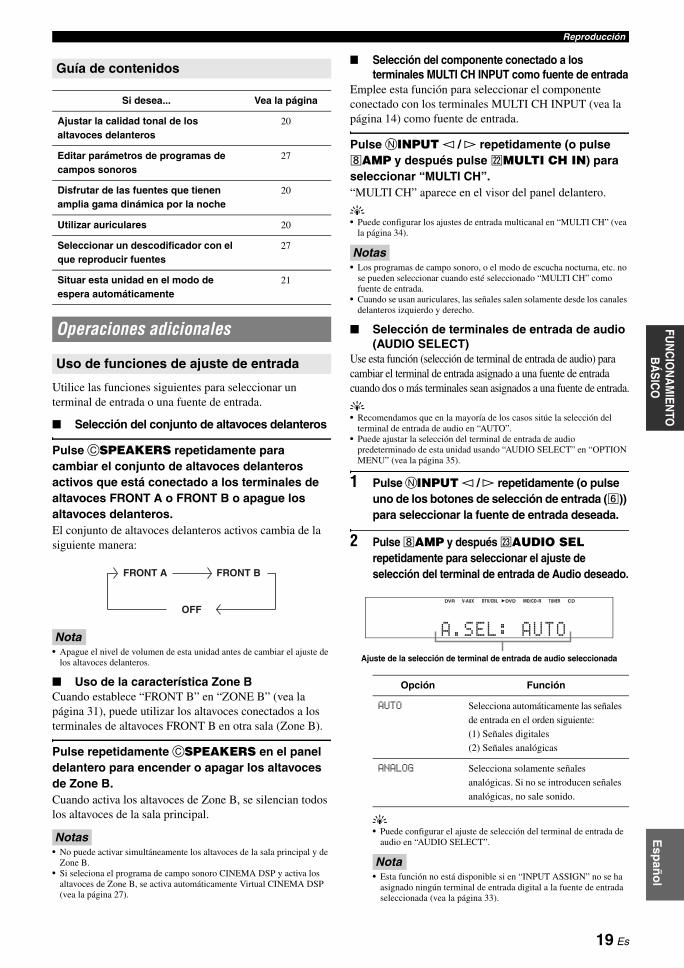
ReproducciónE
spañ
ol
INT
RO
DU
CC
IÓN
INF
OR
MA
CIÓ
N
AD
ICIO
NA
LA
PÉ
ND
ICE
PR
EPA
RA
CIÓ
NF
UN
CIO
NA
MIE
NTO
AVA
NZ
AD
OFU
NC
ION
AM
IENTO
B
ÁS
ICO
Utilice las funciones siguientes para seleccionar unterminal de entrada o una fuente de entrada.
■ Selección del conjunto de altavoces delanteros
Pulse CSPEAKERS repetidamente para cambiar el conjunto de altavoces delanteros activos que está conectado a los terminales de altavoces FRONT A o FRONT B o apague los altavoces delanteros.El conjunto de altavoces delanteros activos cambia de la siguiente manera:
Nota• Apague el nivel de volumen de esta unidad antes de cambiar el ajuste de
los altavoces delanteros.
■ Uso de la característica Zone B Cuando establece “FRONT B” en “ZONE B” (vea la página 31), puede utilizar los altavoces conectados a los terminales de altavoces FRONT B en otra sala (Zone B).
Pulse repetidamente CSPEAKERS en el panel delantero para encender o apagar los altavoces de Zone B.Cuando activa los altavoces de Zone B, se silencian todos los altavoces de la sala principal.
Notas• No puede activar simultáneamente los altavoces de la sala principal y de
Zone B.• Si seleciona el programa de campo sonoro CINEMA DSP y activa los
altavoces de Zone B, se activa automáticamente Virtual CINEMA DSP (vea la página 27).
■ Selección del componente conectado a los terminales MULTI CH INPUT como fuente de entrada
Emplee esta función para seleccionar el componente conectado con los terminales MULTI CH INPUT (vea la página 14) como fuente de entrada.
Pulse NINPUT l / h repetidamente (o pulse hAMP y después pulse vMULTI CH IN) para seleccionar “MULTI CH”.“MULTI CH” aparece en el visor del panel delantero.
y• Puede configurar los ajustes de entrada multicanal en “MULTI CH” (vea
la página 34).
Notas• Los programas de campo sonoro, o el modo de escucha nocturna, etc. no
se pueden seleccionar cuando esté seleccionado “MULTI CH” como fuente de entrada.
• Cuando se usan auriculares, las señales salen solamente desde los canales delanteros izquierdo y derecho.
■ Selección de terminales de entrada de audio (AUDIO SELECT)
Use esta función (selección de terminal de entrada de audio) para cambiar el terminal de entrada asignado a una fuente de entrada cuando dos o más terminales sean asignados a una fuente de entrada.
y• Recomendamos que en la mayoría de los casos sitúe la selección del
terminal de entrada de audio en “AUTO”.• Puede ajustar la selección del terminal de entrada de audio
predeterminado de esta unidad usando “AUDIO SELECT” en “OPTION MENU” (vea la página 35).
1 Pulse NINPUT l / h repetidamente (o pulse uno de los botones de selección de entrada (f)) para seleccionar la fuente de entrada deseada.
2 Pulse hAMP y después wAUDIO SEL repetidamente para seleccionar el ajuste de selección del terminal de entrada de Audio deseado.
y• Puede configurar el ajuste de selección del terminal de entrada de
audio en “AUDIO SELECT”.
Nota• Esta función no está disponible si en “INPUT ASSIGN” no se ha
asignado ningún terminal de entrada digital a la fuente de entrada seleccionada (vea la página 33).
Guía de contenidos
Si desea... Vea la página
Ajustar la calidad tonal de los altavoces delanteros
20
Editar parámetros de programas de campos sonoros
27
Disfrutar de las fuentes que tienen amplia gama dinámica por la noche
20
Utilizar auriculares 20
Seleccionar un descodificador con el que reproducir fuentes
27
Situar esta unidad en el modo de espera automáticamente
21
Operaciones adicionales
Uso de funciones de ajuste de entrada
FRONT A FRONT B
OFF
Opción Función
AUTO Selecciona automáticamente las señales
de entrada en el orden siguiente:
(1) Señales digitales
(2) Señales analógicas
ANALOG Selecciona solamente señales
analógicas. Si no se introducen señales
analógicas, no sale sonido.
��A.SEL:�AUTO
DVR DVD CDV-AUX DTV/CBL MD/CD-R TUNER
Ajuste de la selección de terminal de entrada de audio seleccionada
19 Es

Reproducción
Utilice las siguientes funciones para ajustar la salida de audio o el nivel de los altavoces.
■ Silenciamiento de la salida de audio
Pulse eMUTE en el mando a distancia para silenciar la salida de audio. Pulse de nuevo eMUTE para reanudar la salida de audio.
y• También puede girar PVOLUME (o pulsar mVOLUME +/–) para
reanudar la salida de audio.• Puede configurar el nivel de silenciamiento utilizando “MUTE TYP.” en
“SOUND MENU” (vea la página 33).• El indicador MUTE parpadea en el visor del panel delantero cuando se silencia
la salida de audio y desaparece del visor cuando se reanuda la salida de audio.
■ Ajuste de la calidad tonalUtilice esta función para ajustar el balance de graves y agudos para los canales de altavoces delanteros izquierdo y derecho.
Pulse repetidamente KTONE CONTROL para seleccionar “BASS” o “TREBLE” y después pulse LPROGRAM l / h para ajustar el nivel de respuesta de frecuencia correspondiente.Margen de control: –10 dB a +10 dBCada opción se define de la siguiente manera.
Notas• Los ajustes de altavoces y auriculares se guardan independientemente.• Si aumenta o disminuye el sonido de alta o de baja frecuencia a niveles
extremos, la calidad tonal de los altavoces surround podría no ser adecuada para los altavoces delanteros derecho e izquierdo.
• Esto no afecta al material grabado.
■ Ajuste de nivel de los altavocesPuede ajustar el nivel de salida de cada altavoz mientras escucha una fuente de música. Esto también es posible cuando se reproducen fuentes introducidas por los terminales MULTI CH INPUT.
Nota• Esta operación anulará el ajuste de nivel realizado en “SP LEVEL” (vea
la página 32).
1 Pulse hAMP y después pulse repetidamente jBAND LEVEL TITLE para seleccionar el altavoz que desea ajustar.
y• Una vez pulsado jBAND LEVEL TITLE en el mando a
distancia, también puede seleccionar el altavoz pulsando lk / n.• Hay diferentes canales de altavoces disponibles en función de la
configuración de los altavoces.
2 Pulse ll / h en el mando a distancia (o pulse FPRESET/TUNING l / h) para ajustar el nivel de salida de los altavoces.Margen de control: –10,0 dB a +10,0 dB
Utilice las siguientes funciones para hacer uso de diversas características útiles que se incluyen en esta unidad.
y• Los ajustes iniciales se indican mediante (*) en cada uno de los
siguientes parámetros.
■ Uso de auriculares
Conecte un par de auriculares con un terminal de cable de audio analógico estéreo en el terminal PHONES del panel delantero.
y• El modo SILENT CINEMA se activa automáticamente cuando
selecciona un programa de campo sonoro (vea la página 27).
Notas• Cuando conecte auriculares no saldrán señales por los terminales de los altavoces.• Todas las señales de audio Dolby Digital y DTS se mezclan para los
canales derecho e izquierdo de los auriculares.
■ Selección del modo de escucha nocturnaLos modos de escucha nocturna se han diseñado para mejorar la capacidad de escucha a volúmenes más bajos o por la noche.
1 Pulse ONIGHT (o pulse hAMP y después uNIGHT) repetidamente para seleccionar “NIGHT:CINEMA” o “NIGHT:MUSIC”.Cada opción se define de la siguiente manera.
y• Cuando se selecciona un modo de escucha nocturna, el indicador
NIGHT se enciende en el visor del panel delantero.
2 Pulse ll / h para ajustar el nivel de efectos mientras “NIGHT:CINEMA” o “NIGHT:MUSIC” aparece en el visor del panel delantero.Cada opción se define de la siguiente manera.
Uso de las funciones de audio
Opción Función
BASS Ajusta la respuesta de baja frecuencia.
TREBLE Ajusta la respuesta de alta frecuencia.
Opción Descripción
FRONT L Altavoz delantero izquierdo
FRONT R Altavoz delantero derecho
CENTER Altavoz central
SWFR Subwoofer
SUR.L Altavoz surround izquierdo
SUR.R Altavoz surround derecho
Uso de funciones opcionales
Opción Función
NIGHT:CINEMA Reduce la gama dinámica de las
bandas sonoras cinematográficas y
hace que el diálogo sea más fácil de
escuchar a volúmenes más bajos.
NIGHT:MUSIC Conserva la facilidad de escucha para
todos los sonidos.
NIGHT OFF Desactiva esta función.
Opción Función
MIN Reduce ligeramente el nivel de efectos.
MID* Reduce moderadamente el nivel de efectos.
MAX Reduce considerablemente el nivel de efectos.
20 Es
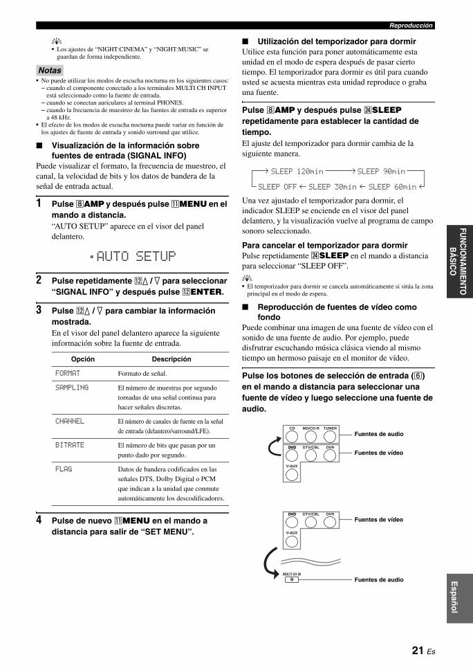
ReproducciónE
spañ
ol
INT
RO
DU
CC
IÓN
INF
OR
MA
CIÓ
N
AD
ICIO
NA
LA
PÉ
ND
ICE
PR
EPA
RA
CIÓ
NF
UN
CIO
NA
MIE
NTO
AVA
NZ
AD
OFU
NC
ION
AM
IENTO
B
ÁS
ICO
y• Los ajustes de “NIGHT:CINEMA” y “NIGHT:MUSIC” se
guardan de forma independiente.
Notas• No puede utilizar los modos de escucha nocturna en los siguientes casos:
– cuando el componente conectado a los terminales MULTI CH INPUT está seleccionado como la fuente de entrada.
– cuando se conectan auriculares al terminal PHONES.– cuando la frecuencia de muestreo de las fuentes de entrada es superior
a 48 kHz.• El efecto de los modos de escucha nocturna puede variar en función de
los ajustes de fuente de entrada y sonido surround que utilice.
■ Visualización de la información sobre fuentes de entrada (SIGNAL INFO)
Puede visualizar el formato, la frecuencia de muestreo, el canal, la velocidad de bits y los datos de bandera de la señal de entrada actual.
1 Pulse hAMP y después pulse kMENU en el mando a distancia.“AUTO SETUP” aparece en el visor del panel delantero.
2 Pulse repetidamente lk / n para seleccionar “SIGNAL INFO” y después pulse lENTER.
3 Pulse lk / n para cambiar la información mostrada.En el visor del panel delantero aparece la siguiente información sobre la fuente de entrada.
4 Pulse de nuevo kMENU en el mando a distancia para salir de “SET MENU”.
■ Utilización del temporizador para dormirUtilice esta función para poner automáticamente esta unidad en el modo de espera después de pasar cierto tiempo. El temporizador para dormir es útil para cuando usted se acuesta mientras esta unidad reproduce o graba una fuente.
Pulse hAMP y después pulse xSLEEP repetidamente para establecer la cantidad de tiempo.El ajuste del temporizador para dormir cambia de la siguiente manera.
Una vez ajustado el temporizador para dormir, el indicador SLEEP se enciende en el visor del panel delantero, y la visualización vuelve al programa de campo sonoro seleccionado.
Para cancelar el temporizador para dormirPulse repetidamente xSLEEP en el mando a distancia para seleccionar “SLEEP OFF”.
y• El temporizador para dormir se cancela automáticamente si sitúa la zona
principal en el modo de espera.
■ Reproducción de fuentes de vídeo como fondo
Puede combinar una imagen de una fuente de vídeo con el sonido de una fuente de audio. Por ejemplo, puede disfrutrar escuchando música clásica viendo al mismo tiempo un hermoso paisaje en el monitor de vídeo.
Pulse los botones de selección de entrada (f) en el mando a distancia para seleccionar una fuente de vídeo y luego seleccione una fuente de audio.
Opción Descripción
FORMAT Formato de señal.
SAMPLING El número de muestras por segundo
tomadas de una señal continua para
hacer señales discretas.
CHANNEL El número de canales de fuente en la señal
de entrada (delantero/surround/LFE).
BITRATE El número de bits que pasan por un
punto dado por segundo.
FLAG Datos de bandera codificados en las
señales DTS, Dolby Digital o PCM
que indican a la unidad que conmute
automáticamente los descodificadores.
;AUTO SETUP
SLEEP 120min SLEEP 90min
SLEEP 60minSLEEP 30minSLEEP OFF
DVD
V-AUX
DTV/CBL DVR
CD MD/CD-R TUNER
DVD
V-AUX
DTV/CBL DVR
DVD
DVD
MULTI CH IN9
Fuentes de audio
Fuentes de vídeo
Fuentes de vídeo
Fuentes de audio
21 Es
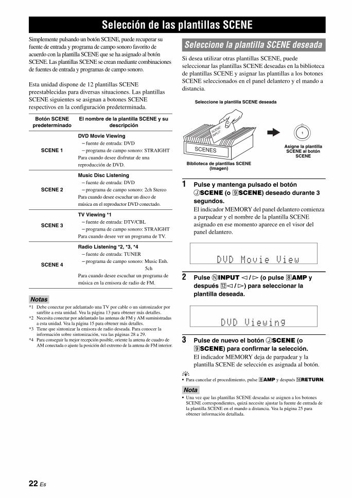
Simplemente pulsando un botón SCENE, puede recuperar su fuente de entrada y programa de campo sonoro favorito de acuerdo con la plantilla SCENE que se ha asignado al botón SCENE. Las plantillas SCENE se crean mediante combinaciones de fuentes de entrada y programas de campo sonoro.
Esta unidad dispone de 12 plantillas SCENE preestablecidas para diversas situaciones. Las plantillas SCENE siguientes se asignan a botones SCENE respectivos en la configuración predeterminada.
Notas*1 Debe conectar por adelantado una TV por cable o un sintonizador por
satélite a esta unidad. Vea la página 13 para obtener más detalles.*2 Necesita conectar por adelantado las antenas de FM y AM suministradas
a esta unidad. Vea la página 15 para obtener más detalles.*3 Tiene que sintonizar la emisora de radio deseada. Para conocer la
información sobre sintonización, vea las páginas 28 a 29.*4 Para conseguir la mejor recepción posible, oriente la antena de cuadro de
AM conectada o ajuste la posición del extremo de la antena de FM interior.
Si desea utilizar otras plantillas SCENE, puede seleccionar las plantillas SCENE deseadas en la biblioteca de plantillas SCENE y asignar las plantillas a los botones SCENE seleccionados en el panel delantero y el mando a distancia.
1 Pulse y mantenga pulsado el botón JSCENE (o iSCENE) deseado durante 3 segundos.El indicador MEMORY del panel delantero comienza a parpadear y el nombre de la plantilla SCENE asignado en ese momento aparece en el visor del panel delantero.
2 Pulse NINPUT l / h (o pulse hAMP y después ll / h) para seleccionar la plantilla deseada.
3 Pulse de nuevo el botón JSCENE (o iSCENE) para confirmar la selección.El indicador MEMORY deja de parpadear y la plantilla SCENE de selección es asignada al botón.
y• Para cancelar el procedimiento, pulse hAMP y después nRETURN.
Nota• Una vez que las plantillas SCENE deseadas se asignen a los botones
SCENE correspondientes, quizá necesite ajustar la fuente de entrada de la plantilla SCENE en el mando a distancia. Vea la página 25 para obtener información detallada.
Selección de las plantillas SCENE
Botón SCENE predeterminado
El nombre de la plantilla SCENE y su descripción
SCENE 1
DVD Movie Viewing– fuente de entrada: DVD
– programa de campo sonoro: STRAIGHT
Para cuando desee disfrutar de una
reproducción de DVD.
SCENE 2
Music Disc Listening– fuente de entrada: DVD
– programa de campo sonoro: 2ch Stereo
Para cuando desee escuchar un disco de
música en el reproductor DVD conectado.
SCENE 3
TV Viewing *1– fuente de entrada: DTV/CBL
– programa de campo sonoro: STRAIGHT
Para cuando desee ver un programa de TV.
SCENE 4
Radio Listening *2, *3, *4– fuente de entrada: TUNER
– programa de campo sonoro: Music Enh.
5ch
Para cuando desee escuchar un programa de
música en la emisora de radio de FM.
Seleccione la plantilla SCENE deseada
1
Seleccione la plantilla SCENE deseada
Biblioteca de plantillas SCENE (Imagen)
Asigne la plantilla SCENE al botón
SCENE
DVD Movie View
DVD Viewing
22 Es
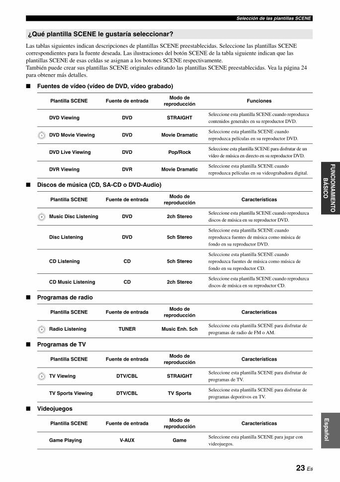
Selección de las plantillas SCENEE
spañ
ol
INT
RO
DU
CC
IÓN
INF
OR
MA
CIÓ
N
AD
ICIO
NA
LA
PÉ
ND
ICE
PR
EPA
RA
CIÓ
NF
UN
CIO
NA
MIE
NTO
AVA
NZ
AD
OFU
NC
ION
AM
IENTO
B
ÁS
ICO
Las tablas siguientes indican descripciones de plantillas SCENE preestablecidas. Seleccione las plantillas SCENE correspondientes para la fuente deseada. Las ilustraciones del botón SCENE de la tabla siguiente indican que las plantillas SCENE de esas celdas se asignan a los botones SCENE respectivamente.También puede crear sus plantillas SCENE originales editando las plantillas SCENE preestablecidas. Vea la página 24 para obtener más detalles.
■ Fuentes de vídeo (vídeo de DVD, vídeo grabado)
■ Discos de música (CD, SA-CD o DVD-Audio)
■ Programas de radio
■ Programas de TV
■ Videojuegos
¿Qué plantilla SCENE le gustaría seleccionar?
Plantilla SCENE Fuente de entradaModo de
reproducciónFunciones
DVD Viewing DVD STRAIGHTSeleccione esta plantilla SCENE cuando reproduzca
contenidos generales en su reproductor DVD.
DVD Movie Viewing DVD Movie DramaticSeleccione esta plantilla SCENE cuando
reproduzca películas en su reproductor DVD.
DVD Live Viewing DVD Pop/RockSeleccione esta plantilla SCENE para disfrutar de un
vídeo de música en directo en su reproductor DVD.
DVR Viewing DVR Movie DramaticSeleccione esta plantilla SCENE cuando
reproduzca películas en su videograbadora digital.
Plantilla SCENE Fuente de entradaModo de
reproducciónCaracterísticas
Music Disc Listening DVD 2ch StereoSeleccione esta plantilla SCENE cuando reproduzca
discos de música en su reproductor DVD.
Disc Listening DVD 5ch StereoSeleccione esta plantilla SCENE cuando
reproduzca fuentes de música como música de
fondo en su reproductor DVD.
CD Listening CD 5ch StereoSeleccione esta plantilla SCENE cuando
reproduzca fuentes de música como música de
fondo en su reproductor CD.
CD Music Listening CD 2ch StereoSeleccione esta plantilla SCENE cuando reproduzca
discos de música en su reproductor CD.
Plantilla SCENE Fuente de entradaModo de
reproducciónCaracterísticas
Radio Listening TUNER Music Enh. 5chSeleccione esta plantilla SCENE para disfrutar de
programas de radio de FM o AM.
Plantilla SCENE Fuente de entradaModo de
reproducciónCaracterísticas
TV Viewing DTV/CBL STRAIGHTSeleccione esta plantilla SCENE para disfrutar de
programas de TV.
TV Sports Viewing DTV/CBL TV SportsSeleccione esta plantilla SCENE para disfrutar de
programas deporitvos en TV.
Plantilla SCENE Fuente de entradaModo de
reproducciónCaracterísticas
Game Playing V-AUX GameSeleccione esta plantilla SCENE para jugar con
videojuegos.
1
2
4
3
23 Es
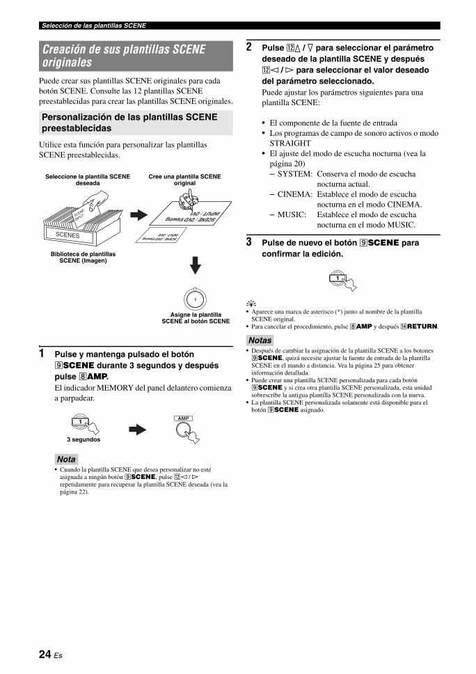
Selección de las plantillas SCENE
Puede crear sus plantillas SCENE originales para cada botón SCENE. Consulte las 12 plantillas SCENE preestablecidas para crear las plantillas SCENE originales.
Utilice esta función para personalizar las plantillas SCENE preestablecidas.
1 Pulse y mantenga pulsado el botón iSCENE durante 3 segundos y después pulse hAMP.El indicador MEMORY del panel delantero comienza a parpadear.
Nota• Cuando la plantilla SCENE que desea personalizar no esté
asignada a ningún botón iSCENE, pulse ll / h repetidamente para recuperar la plantilla SCENE deseada (vea la página 22).
2 Pulse lk / n para seleccionar el parámetro deseado de la plantilla SCENE y después ll / h para seleccionar el valor deseado del parámetro seleccionado.Puede ajustar los parámetros siguientes para una plantilla SCENE:
• El componente de la fuente de entrada• Los programas de campo de sonoro activos o modo
STRAIGHT• El ajuste del modo de escucha nocturna (vea la
página 20)– SYSTEM: Conserva el modo de escucha
nocturna actual.– CINEMA: Establece el modo de escucha
nocturna en el modo CINEMA.– MUSIC: Establece el modo de escucha
nocturna en el modo MUSIC.
3 Pulse de nuevo el botón iSCENE para confirmar la edición.
y• Aparece una marca de asterisco (*) junto al nombre de la plantilla
SCENE original.• Para cancelar el procedimiento, pulse hAMP y después nRETURN.
Notas• Después de cambiar la asignación de la plantilla SCENE a los botones iSCENE, quizá necesite ajustar la fuente de entrada de la plantilla SCENE en el mando a distancia. Vea la página 25 para obtener información detallada.
• Puede crear una plantilla SCENE personalizada para cada botón iSCENE y si crea otra plantilla SCENE personalizada, esta unidad sobrescribe la antigua plantilla SCENE personalizada con la nueva.
• La plantilla SCENE personalizada solamente está disponible para el botón iSCENE asignado.
Creación de sus plantillas SCENE originales
Personalización de las plantillas SCENE preestablecidas
: DVD Viewing: DVD
SCENEINPUT
SCENE : DVD Viewing
1
Seleccione la plantilla SCENE deseada
Cree una plantilla SCENE original
Biblioteca de plantillas SCENE (Imagen)
Asigne la plantilla SCENE al botón SCENE
AMP1
3 segundos
1
24 Es
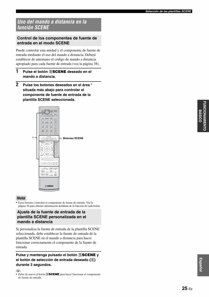
Selección de las plantillas SCENEE
spañ
ol
INT
RO
DU
CC
IÓN
INF
OR
MA
CIÓ
N
AD
ICIO
NA
LA
PÉ
ND
ICE
PR
EPA
RA
CIÓ
NF
UN
CIO
NA
MIE
NTO
AVA
NZ
AD
OFU
NC
ION
AM
IENTO
B
ÁS
ICO
Puede controlar esta unidad y el componente de fuente de entrada mediante el uso del mando a distancia. Deberá establecer de antemano el código de mando a distancia apropiado para cada fuente de entrada (vea la página 38).
1 Pulse el botón iSCENE deseado en el mando a distancia.
2 Pulse los botones deseados en el área * situada más abajo para controlar el componente de fuente de entrada de la plantilla SCENE seleccionada.
Nota• Estos botones controlan el componente de fuente de entrada. Vea la
página 36 para obtener información detallada de la función de cada botón.
Si personaliza la fuente de entrada de la plantilla SCENE seleccionada, debe establecer la fuente de entrada de la plantilla SCENE en el mando a distancia para hacer funcionar correctamente el componente de la fuente de entrada.
Pulse y mantenga pulsado el botón iSCENE y el botón de selección de entrada deseado (f) durante 3 segundos.
y• Pulse de nuevo el botón iSCENE para hacer funcionar el componente
de fuente de entrada.
Uso del mando a distancia en la función SCENE
Control de los componentes de fuente de entrada en el modo SCENE
Ajuste de la fuente de entrada de la plantilla SCENE personalizada en el mando a distancia
REC
SUR. DECODE
NIGHTSTRAIGHT
MULTI CH IN AUDIO SEL SLEEP
ENHANCERl PROG h
TV MUTETV INPUT TV VOL
TV CH
POWER
AMP
STANDBYPOWER
MUTE
POWER
8
10
7
09
65
4321
ENT
DVD
V-AUX D E
DTV/CBL DVR
CD MD/CD-R TUNER
MENU VOLUMETITLE
ENTER
BAND LEVEL
DISPLAYRETURN
AVTV
SCENE
4321
A B C
* Botones SCENE
25 Es
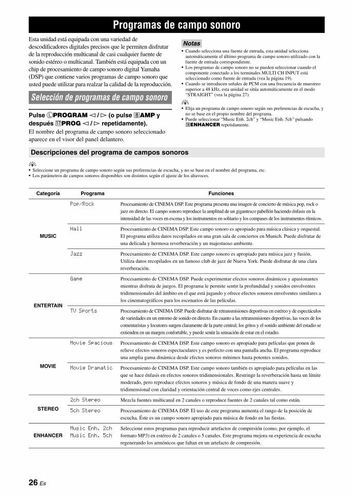
Esta unidad está equipada con una variedad de descodificadores digitales precisos que le permiten disfrutar de la reproducción multicanal de casi cualquier fuente de sonido estéreo o multicanal. También está equipada con un chip de procesamiento de campo sonoro digital Yamaha (DSP) que contiene varios programas de campo sonoro que usted puede utilizar para realzar la calidad de la reproducción.
Pulse LPROGRAM l / h (o pulse hAMP y después qPROG l / h repetidamente).El nombre del programa de campo sonoro seleccionado aparece en el visor del panel delantero.
Notas• Cuando selecciona una fuente de entrada, esta unidad selecciona
automáticamente el último programa de campo sonoro utilizado con la fuente de entrada correspondiente.
• Los programas de campo sonoro no se pueden seleccionar cuando el componente conectado a los terminales MULTI CH INPUT está seleccionado como fuente de entrada (vea la página 19).
• Cuando se introducen señales de PCM con una frecuencia de muestreo superior a 48 kHz, esta unidad se sitúa automáticamente en el modo “STRAIGHT” (vea la página 27).
y• Elija un programa de campo sonoro según sus preferencias de escucha, y
no se base en el propio nombre del programa.• Puede seleccionar “Music Enh. 2ch” y “Music Enh. 5ch” pulsando rENHANCER repetidamente.
y• Seleccione un programa de campo sonoro según sus preferencias de escucha, y no se base en el nombre del programa, etc.• Los parámetros de campos sonoros disponibles son distintos según el ajuste de los altavoces.
Programas de campo sonoro
Selección de programas de campo sonoro
Descripciones del programa de campos sonoros
Categoría Programa Funciones
MUSIC
Pop/Rock Procesamiento de CINEMA DSP. Este programa presenta una imagen de concierto de música pop, rock o
jazz en directo. El campo sonoro reproduce la amplitud de un gigantesco pabellón haciendo énfasis en la
intensidad de las voces en escena y los instrumentos en solitario y los compases de los instrumentos rítmicos.
Hall Procesamiento de CINEMA DSP. Este campo sonoro es apropiado para música clásica y orquestal.
El programa utiliza datos recopilados en una gran sala de conciertos en Munich. Puede disfrutar de
una delicada y hermosa reverberación y un majestuoso ambiente.
Jazz Procesamiento de CINEMA DSP. Este campo sonoro es apropiado para música jazz y fusión.
Utiliza datos recopilados en un famoso club de jazz de Nueva York. Puede disfrutar de una clara
reverberación.
ENTERTAIN
Game Procesamiento de CINEMA DSP. Puede experimentar efectos sonoros dinámicos y apasionantes
mientras disfruta de juegos. El programa le permite sentir la profundidad y sonidos envolventes
tridimensionales del ámbito en el que está jugando y ofrece efectos sonoros envolventes similares a
los cinematográficos para los escenarios de las películas.
TV Sports Procesamiento de CINEMA DSP. Puede disfrutar de retransmisiones deportivas en estéreo y de espectáculos
de variedades en un entorno de sonido en directo. En cuanto a las retransmisiones deportivas, las voces de los
comentaristas y locutores surgen claramente de la parte central; los gritos y el sonido ambiente del estadio se
extienden en un margen confortable, y puede sentir la sensación de estar en el estadio.
MOVIE
Movie Spacious Procesamiento de CINEMA DSP. Este campo sonoro es apropiado para películas que ponen de
relieve efectos sonoros espectaculares y es perfecto con una pantalla ancha. El programa reproduce
una amplia gama dinámica desde efectos sonoros mínimos hasta potentes sonidos.
Movie Dramatic Procesamiento de CINEMA DSP. Este campo sonoro también es apropiado para películas en las
que se hace énfasis en efectos sonoros tridimensionales. Restringe la reverberación hasta un límite
moderado, pero reproduce efectos sonoros y música de fondo de una manera suave y
tridimensional con claridad y orientación central de voces como ejes centrales.
STEREO
2ch Stereo Mezcla fuentes multicanal en 2 canales o reproduce fuentes de 2 canales tal como están.
5ch Stereo Procesamiento de CINEMA DSP. El uso de este programa aumenta el rango de la posición de
escucha. Éste es un campo sonoro apropiado para música de fondo en las fiestas.
ENHANCERMusic Enh. 2ch
Music Enh. 5ch
Seleccione estos programas para reproducir artefactos de compresión (como, por ejemplo, el
formato MP3) en estéreo de 2 canales o 5 canales. Este programa mejora su experiencia de escucha
regenerando los armónicos que faltan en un artefacto de compresión.
26 Es

Programas de campo sonoroE
spañ
ol
INT
RO
DU
CC
IÓN
INF
OR
MA
CIÓ
N
AD
ICIO
NA
LA
PÉ
ND
ICE
PR
EPA
RA
CIÓ
NF
UN
CIO
NA
MIE
NTO
AVA
NZ
AD
OFU
NC
ION
AM
IENTO
B
ÁS
ICO
■ Selección de descodificadores para fuentes de 2 canales (modo de descodificador surround)
Las señales introducidas desde fuentes de 2 canales también se pueden reproducir en múltiples canales.
Pulse hAMP y después pulse sSUR. DECODE repetidamente para seleccionar un descodificador.Puede seleccionar entre los siguientes descodificadores dependiendo del tipo de fuente que esté reproduciendo y sus preferencias personales.
■ Edición de parámetros de campos sonorosAunque puede disfrutar de sonido de buena calidad con los parámetros predeterminados en la fábrica, puede cambiar algunos de los parámetros para adaptar mejor la fuente de entrada o su sala de escucha.
1 Mientras escucha una fuente, pulse hAMP y después pulse lk / n para seleccionar un parámetro deseado.
2 Pulse ll / h para cambiar el valor del parámetro.
Nota• No puede cambiar valores de parámetros cuando “MEM.GUARD” en
“OPTION MENU” está establecido en “ON” (vea la página 34).
y• Los ajustes iniciales se indican mediante (*) en cada uno de los
siguientes parámetros.
Para Pop/Rock, Hall, Jazz, Game, TV Sports, Movie Spacious y Movie Dramatic:
Para PRO LOGIC II Music:
Para Music Enh. 2ch y Music Enh. 5ch
■ Uso de programas de campo sonoro sin altavoces surround (Virtual CINEMA DSP)
Virtual CINEMA DSP le permite disfrutar de los programas CINEMA DSP de campo sonoro sin altavoces surround. Cuando sitúa “SUR. L/R” en “NONE” (vea la página 32), Virtual CINEMA DSP se activa automáticamente siempre que selecciona un programa de campo sonoro CINEMA DSP (vea la página 26).
■ Disfrute de fuentes multicanal y programas de campo sonoro con auriculares (SILENT CINEMA)
SILENT CINEMA le permite disfrutar de la música o el sonido de películas multicanal con auriculares convencionales. SILENT CINEMA se activa automáticamente siempre que se conectan auriculares en el terminal PHONES mientras se escuchan programas de campo sonoro CINEMA DSP (vea la página 26).
y• Cuando se activa, el indicador SILENT CINEMA se enciende en el visor
del panel delantero.
■ Para disfrutar de fuentes de entrada no procesadas (Modo de descodificación directa)
Cuando esta unidad esté en el modo “STRAIGHT”, las fuentes estéreo de 2 canales sólo saldrán por los altavoces delanteros derecho e izquierdo. Las fuentes de múltiples canales se descodifican directamente para los canales apropiados sin ningún proceso de efectos adicional.
Pulse MSTRAIGHT (o pulse hAMP y después tSTRAIGHT) para seleccionar “STRAIGHT”.“STRAIGHT” aparece en el visor del panel delantero.
Desactivación del modo “STRAIGHT”Pulse de nuevo MSTRAIGHT (o tSTRAIGHT), de forma que “STRAIGHT” desaparezca del visor del panel delantero.
STANDARD Función
PRO LOGIC Procesamiento Dolby Pro Logic para
cualquier fuente
PLII Movie Procesamiento Dolby Pro Logic II para
fuentes de películas
PLII Music Procesamiento Dolby Pro Logic II para
fuentes de música
PLII Game Procesamiento Dolby Pro Logic II para
fuentes de juegos
Nivel de DSP DSP LEVEL
Función: Ajusta el nivel de los efectos.
Opciones: MIN, MID*, MAX
Panorama PANORAMA
Función: Envía señales estéreo a los altavoces
surround y a los altavoces delanteros para
proporcionar un efecto envolvente.
Opciones: OFF*, ON
Dimensión DIMENSION
Función: Ajusta gradualmente el campo sonoro hacia
la parte delantera o trasera.
Margen de control: –3 (hacia la parte trasera) a +3 (hacia la
parte delantera), el ajuste inicial es STD
(estándar).
Anchura central CT WIDTH
Función: Ajusta la imagen central de los tres altavoces
delanteros en diversos grados. Un valor más
grande ajusta la imagen central hacia los
altavoces delanteros derecho e izquierdo.
Margen de control: 0 (el sonido de canal central sale únicamente
por el altavoz central) a 7 (el sonido del
canal central sale únicamente por los
altavoces delanteros derecho e izquierdo), el
ajuste inicial es 3.
Nivel de efectos
Función: Ajusta el nivel de los efectos.
Opciones: LOW, HIGH*
27 Es

Puede emplear dos modos de sintonización para escuchar una emisora de FM/AM deseada:
■ Modo de sintonización de frecuenciaPuede buscar o especificar, manual o automáticamente, la frecuencia de la emisora deseada de FM/AM (vea “Operaciones de sintonización de FM/AM” en esta página).
■ Modo de presintonizaciónPuede presintonizar por adelantado las emisoras de FM/AM deseadas y después volver a usar la emisora especificando el grupo y número presintonizado (vea “Selección de emisoras presintonizadas” en la página 29).
Nota• Para conseguir la mejor recepción posible, oriente la antena de cuadro de
AM conectada o ajuste la posición del extremo de la antena de FM interior.
1 Pulse repetidamente NINPUT l / h de forma que aparezca “TUNER” en el visor del panel delantero.
2 Pulse GBAND para seleccionar la banda de recepción (FM o AM).
3 Para buscar la emisora automáticamente, pulse ITUNING AUTO/MAN’L de forma que el indicador AUTO se encienda en el visor del panel delantero. Para buscar la emisora manualmente, pulse de nuevo ITUNING AUTO/MAN’L, de forma que el indicador AUTO desaparezca del visor del panel delantero.
Si aparecen dos puntos (:) en el visor del panel delantero, la sintonización automática/manual no será posible. Pulse DEDIT PRESET/TUNING para apagar los dos puntos (:).
4 Para comenzar la sintonización automática, pulse una vez FPRESET/TUNING l / h. Para sintonizar manualmente la emisora deseada, pulse repetidamente FPRESET/TUNING l / h.Cuando esta unidad sintoniza una emisora, el indicador TUNED se enciende y la frecuencia de la emisora recibida se muestra en el visor del panel delantero.
• Para sintonizar una frecuencia más alta, pulse FPRESET/TUNING h.
• Para sintonizar una frecuencia más baja, pulse FPRESET/TUNING l.
Nota• Si la señal de la emisora que selecciona es débil, sintonícela manualmente.
Utilice esta función para almacenar hasta 40 emisoras (A1 a E8: 8 números de emisoras presintonizadas en cada uno de los 5 grupos de emisoras presintonizadas). Utilice el preajuste manual o automático de emisoras para presintonizar las emisoras deseadas.
Puede utilizar la función de presintonización automática para guardar en orden hasta 40 emisoras de FM de señal intensa.
1 Pulse repetidamente NINPUT l / h de forma que aparezca “TUNER” en el visor del panel delantero.
2 Pulse GBAND para seleccionar “FM” como la banda de recepción.
3 Pulse y mantenga pulsado HMEMORY durante más de 3 segundos.El número de la emisora presintonizada y los indicadores MEMORY y AUTO parpadearán. Después de unos 5 segundos empieza la presintonía automática desde la frecuencia actual y ésta avanza hacia las frecuencias más altas.
Cuando termina la presintonización automática, el visor del panel delantero muestra la frecuencia de la última emisora presintonizada.
Sintonización de FM/AM
NotaAsegúrese de establecer el paso de frecuencias del sintonizador según la separación de frecuencias de su zona antes de sintonizar una emisora de radio. Vea la página 39 para conocer el ajuste del paso de frecuencias del sintonizador.
Descripción general
Operaciones de sintonización de FM/AM
AUTO
A AM 1440 kHz
Se enciende durante la sintonización automática
Sin dos puntos (:)
Emisoras presintonizadas de FM/AM
Presintonización automática de emisoras
AUTO TUNED
A AM 1530 kHz
Se enciende
AUTO MEMORY
A1:FM 87.50MHz
Parpadea
Parpadea
28 Es

Sintonización de FM/AME
spañ
ol
INT
RO
DU
CC
IÓN
INF
OR
MA
CIÓ
N
AD
ICIO
NA
LA
PÉ
ND
ICE
PR
EPA
RA
CIÓ
NF
UN
CIO
NA
MIE
NTO
AVA
NZ
AD
OFU
NC
ION
AM
IENTO
B
ÁS
ICO
y• Puede seleccionar el grupo de emisoras presintonizadas y el número de
emisoras presintonizadas donde se almacenará la primera emisora recibida pulsando EA/B/C/D/E y después FPRESET/TUNING l / h.
Notas• Cualquier dato de emisora guardado bajo un número de emisora
presintonizada se cancela al guardar una emisora nueva bajo el mismo número de emisora presintonizada.
• Sólo las emisoras de FM con suficiente intensidad de señal se guardan automáticamente mediante la presintonización automática. Si la emisora que quiere guardar tiene una intensidad de señal débil, sintonícela manualmente y guárdela como se describe en “Presintonización manual de las emisoras” en esta página.
Emplee esta función para guardar manualmente las emisoras de FM o de AM.
1 Sintonice una emisora.Vea la página 28 para usar las instrucciones de sintonización.
2 Pulse HMEMORY.El indicador MEMORY parpadea en el visor del panel delantero durante unos 30 segundos.
3 Pulse repetidamente EA/B/C/D/E y FPRESET/TUNING l / h para seleccionar un grupo y número de emisoras presintonizadas (A1 a E8) mientras el indicador MEMORY está parpadeando.Verifique que los dos puntos (:) aparezcan en el visor del panel delantero.• Para seleccionar un grupo y número de presintonías
más alto, pulse FPRESET/TUNING h.• Para seleccionar un grupo y número de presintonías
más alto, pulse FPRESET/TUNING l.
4 Pulse HMEMORY mientras el indicador MEMORY está parpadeando.La banda y la frecuencia de la emisora aparecen en el visor del panel delantero con el número y grupo de emisoras presintonizadas que usted ha seleccionado.
Puede sintonizar simplemente cualquier emisora deseada seleccionando el grupo de emisoras presintonizadas y el número bajo el cual se guarda.
1 Pulse repetidamente EA/B/C/D/E (o ll / h) para seleccionar el grupo de emisoras presintonizadas (A a E).La letra del grupo de emisoras presintonizadas aparece en el visor del panel delantero y cambia cada vez que usted pulsa el botón.
2 Pulse FPRESET/TUNING l / h (o lk / n) para seleccionar el número de emisora presintonizada deseado (1 a 8).El número y grupo de emisoras presintonizadas aparece en el visor del panel delantero junto con la banda y la frecuencia de la emisora.
y• También puede seleccionar el número de emisora presintonizada deseado
(1 a 8) pulsando directamente los botones numéricos (y).
Puede intercambiar las asignaciones de dos emisoras presintonizas entre ellas. El ejemplo de abajo describe el procedimiento para intercambiar la emisora presintonizada “E1” y “A5”.
1 Seleccione la emisora presintonizada “E1” utilizando EA/B/C/D/E y FPRESET/TUNING l / h.Consulte “Selección de emisoras presintonizadas” en esta página.
2 Pulse y mantenga pulsado DEDIT PRESET/TUNING durante más de 3 segundos.“E1” y el indicador MEMORY parpadean en el visor del panel delantero.
3 Seleccione la emisora presintonizada “A5” utilizando EA/B/C/D/E y FPRESET/TUNING l / h.“A5” y el indicador MEMORY parpadean en el visor del panel delantero.Consulte “Selección de emisoras presintonizadas” en esta página.
4 Pulse de nuevo DEDIT PRESET/TUNING.“EXCHANGE E1-A5” aparece en el visor del panel delantero y las asignaciones de las dos emisoras presintonizadas se intercambian.
Presintonización manual de las emisoras
Selección de emisoras presintonizadas
TUNED MEMORY
:C3 AM 630 kHz
Parpadea
Número y grupo de presintonías
TUNED
:C3 AM 630 kHz
La emisora mostrada se ha almacenado como C3.
Cuando realice esta operación con el mando a distancia, pulse fTUNER para seleccionar “TUNER” como la fuente de entrada.
Intercambio de emisoras presintonizadas
MEMORY
:A5 FM 90.50MHz
Parpadea
Parpadea
29 Es
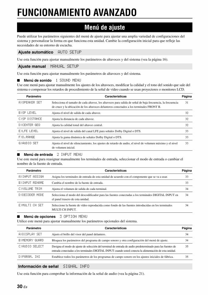
FUNCIONAMIENTO AVANZADO
Puede utilizar los parámetros siguientes del menú de ajuste para ajustar una amplia variedad de configuraciones del sistema y personalizar la forma en que funciona esta unidad. Cambie la configuración inicial para que refleje las necesidades de su entorno de escucha.
Use esta función para ajustar manualmente los parámetros de altavoces y del sistema (vea la página 16).
Use esta función para ajustar manualmente los parámetros de altavoces y del sistema.
■ Menú de sonido 1 SOUND MENUUse este menú para ajustar manualmente los ajustes de los altavoces, modificar la calidad y el tono del sonido que sale del sistema o compensar los retardos de procedimiento de la señal de vídeo cuando se usan proyectores o monitores LCD.
■ Menú de entrada 2 INPUT MENUUse este menú para reasignar manualmente los terminales de entrada, seleccionar el modo de entrada o cambiar el nombre de la fuente de entrada.
■ Menú de opciones 3 OPTION MENUUtilice este menú para ajustar manualmente los parámetros opcionales del sistema.
Use esta función para comprobar la información de la señal de audio (vea la página 21).
Menú de ajuste
Ajuste automático AUTO SETUP
Ajuste manual MANUAL SETUP
Parámetro Características Página
A)SPEAKER SET Selecciona el tamaño de cada altavoz, los altavoces para salida de señal de baja frecuencia, la frecuencia
de cruce y la ubicación de los altavoces delanteros conectados a los terminales FRONT B.
31
B)SP LEVEL Ajusta el nivel de salida de cada altavoz. 32
C)SP DISTANCE Ajusta la distancia de cada altavoz. 32
D)CENTER GEQ Ajusta la calidad tonal del altavoz central. 32
E)LFE LEVEL Ajusta el nivel de salida del canal LFE para señales Dolby Digital o DTS. 33
F)D.RANGE Ajusta la gama dinámica de señales Dolby Digital o DTS. 33
G)AUDIO SET Ajusta el nivel de silenciamiento, los ajustes de retardo de audio, el nivel de volumen máximo y el nivel
de volumen inicial.
33
Parámetro Características Página
A)INPUT ASSIGN Asigna los terminales de entrada de esta unidad de acuerdo con el componente que se va a usar. 33
B)INPUT RENAME Cambia el nombre de la fuente de entrada. 33
C)VOLUME TRIM Ajusta el volumen de salida de cada terminal. 34
D)DECODER MODE Selecciona el modo del descodificador para las fuentes conectadas a los terminales DIGITAL INPUT en
el panel trasero de esta unidad.
34
E)MULTI CH SET Seleccione la fuente de vídeo reproducida como fondo de las fuentes introducidas en los terminales
MULTI CH INPUT.
34
Parámetro Características Página
A)DISPLAY SET Ajusts el brillo del visor del panel delantero. 34
B)MEMORY GUARD Bloquea los parámetros del programa de campo sonoro y otra configuración del menú de ajuste. 34
C)AUDIO SELECT Designa el modo de ajuste de selección del terminal de entrada de audio predeterminado para las fuentes de
entrada conectadas a los terminales DIGITAL INPUT cuando usted conecta la alimentación de esta unidad.
35
D)PARAM. INI Establece todos los parámetros de los programas de campo sonoro en los ajustes iniciales de fábrica. 35
Información de señal SIGNAL INFO
30 Es

Menú de ajusteE
spañ
ol
INT
RO
DU
CC
IÓN
INF
OR
MA
CIÓ
N
AD
ICIO
NA
LA
PÉ
ND
ICE
PR
EPA
RA
CIÓ
NF
UN
CIO
NA
MIE
NTO
BÁ
SIC
OFU
NC
ION
AM
IENTO
AVA
NZA
DO
Utilice el mando a distancia para acceder y ajustar cada parámetro.
y• Puede cambiar los parámetros del menú de ajuste mientras esta unidad
está reproduciendo sonido.
1 Pulse hAMP y después pulse kMENU en el mando a distancia.“AUTO SETUP” aparece en el visor del panel delantero.
2 Pulse lk / n para seleccionar “MANUAL SETUP”.
3 Pulse lENTER para introducir “MANUAL SETUP”.“1 SOUND MENU” aparece en el visor del panel delantero.
4 Pulse repetidamente lk / n y después pulse lENTER para seleccionar y entrar en el menú deseado.Los menús siguientes aparecen en el visor del panel delantero cuando pulsa repetidamente lk / n.
5 Pulse repetidamente lk / n y después pulse lENTER para seleccionar y entrar en el submenú deseado.• Repita este paso para navegar por y entrar en los
elementos que desea ajustar.• Para regresar al nivel del menú anterior, pulse nRETURN.
6 Pulse lk / n para seleccionar el parámetro deseado y después ll / h para cambiar el valor del parámetro.• Pulse lh para aumentar el valor.• Pulse ll para reducir el valor.
7 Pulse kMENU para salir del menú de ajuste.
Utilice este menú para ajustar manualmente los ajustes de los altavoces o compensar los retardos de procesamiento de la señal de vídeo cuando se utilicen proyectores o monitores LCD.
y• Los ajustes iniciales se indican mediante (*) en cada uno de los
siguientes parámetros.
Use esta función para hacer manualmente cualquier ajuste de altavoz.
■ FRONT B ajuste de los altavoces FRONT BUse esta función para seleccionar la ubicación de los altavoces delanteros conectados a los terminales FRONT B.
Notas• Si conecta auriculares al terminal PHONES de esta unidad, el sonido sale
por ambos auriculares y los terminales FRONT B mientras “FRONT B” se establece en “ZONE B”.
• Si se selecciona un programa DSP cuando “FRONT B” se establece en “ZONE B”, esta unidad entra automáticamente en el modo Virtual CINEMA DSP (vea la página 27).
■ Altavoces delanteros, Altavoz central, Altavoces surround izquierdo/derechoFRONT, CENTER, SUR. LR
Seleccione “LARGE (LRG)” o “SMALL (SML)” dependiendo del tamaño de cada uno de sus altavoces. Cuando el Altavoz central o los Altavoces surround no estén conectados, seleccione “NONE”.Ajuste inicial:
FRONT: “LARGE”CENTER: “SML”SUR. LR: “SML”
Notas• Cuando “BASS OUT” está establecido en “FRONT” en esta página,
usted puede seleccionar solamente “LARGE” en “FRONT”. Si “FRONT” está establecido de antemano en un ajuste distinto de “LARGE”, esta unidad cambia automáticamente el valor a “LARGE”.
• Cuando selecciona “NONE” en “CENTER”, las señales del canal central se dirigen a los altavoces delanteros izquierdo y derecho.
• Cuando selecciona “NONE” en “SUR. LR”, esta unidad entra automáticamente en el modo Virtual CINEMA DSP (vea la página 27).
■ LFE/Salida de graves BASS OUTUtilice esta función para seleccionar los altavoces que dan salida al LFE (efecto de baja frecuencia) y a las señales de baja frecuencia.
y• Si no está satisfecho con los sonidos graves de sus altavoces, podrá
cambiar estos ajustes según sus preferencias.
Uso del menú de ajuste
MANUAL SETUP .
1 SOUND MENU
1 SOUND MENU
2 INPUT MENU
3 OPTION MENU
1 SOUND MENU
Ajustes de los altavoces A)SPEAKER SET
Opción Condición
FRONT* Cuando los altavoces FRONT B están ubicados en la
zona principal.
ZONE B Cuando los altavoces FRONT B están ubicados en otra zona.
Este ajuste silencia todos los altavoces en la sala principal
cuando FRONT B es seleccionado por CSPEAKERS.
El diámetro del woofer de un altavoz es de 16 cm o mayor: LARGE (LRG)El diámetro del woofer de un altavoz es menor de 16 cm: SMALL (SML)
31 Es
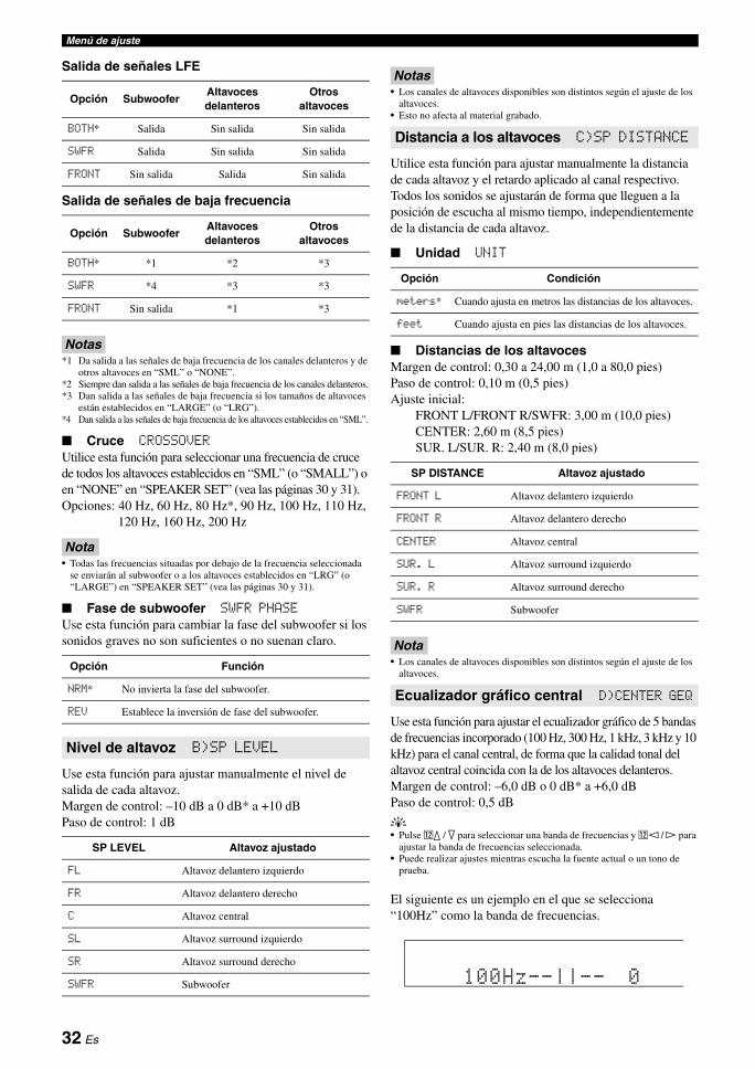
Menú de ajuste
Salida de señales LFE
Salida de señales de baja frecuencia
Notas*1 Da salida a las señales de baja frecuencia de los canales delanteros y de
otros altavoces en “SML” o “NONE”.*2 Siempre dan salida a las señales de baja frecuencia de los canales delanteros.*3 Dan salida a las señales de baja frecuencia si los tamaños de altavoces
están establecidos en “LARGE” (o “LRG”).*4 Dan salida a las señales de baja frecuencia de los altavoces establecidos en “SML”.
■ Cruce CROSSOVERUtilice esta función para seleccionar una frecuencia de cruce de todos los altavoces establecidos en “SML” (o “SMALL”) o en “NONE” en “SPEAKER SET” (vea las páginas 30 y 31).Opciones: 40 Hz, 60 Hz, 80 Hz*, 90 Hz, 100 Hz, 110 Hz,
120 Hz, 160 Hz, 200 Hz
Nota• Todas las frecuencias situadas por debajo de la frecuencia seleccionada
se enviarán al subwoofer o a los altavoces establecidos en “LRG” (o “LARGE”) en “SPEAKER SET” (vea las páginas 30 y 31).
■ Fase de subwoofer SWFR PHASEUse esta función para cambiar la fase del subwoofer si los sonidos graves no son suficientes o no suenan claro.
Use esta función para ajustar manualmente el nivel de salida de cada altavoz.Margen de control: –10 dB a 0 dB* a +10 dBPaso de control: 1 dB
Notas• Los canales de altavoces disponibles son distintos según el ajuste de los
altavoces.• Esto no afecta al material grabado.
Utilice esta función para ajustar manualmente la distancia de cada altavoz y el retardo aplicado al canal respectivo. Todos los sonidos se ajustarán de forma que lleguen a la posición de escucha al mismo tiempo, independientemente de la distancia de cada altavoz.
■ Unidad UNIT
■ Distancias de los altavocesMargen de control: 0,30 a 24,00 m (1,0 a 80,0 pies)Paso de control: 0,10 m (0,5 pies)Ajuste inicial:
FRONT L/FRONT R/SWFR: 3,00 m (10,0 pies)CENTER: 2,60 m (8,5 pies)SUR. L/SUR. R: 2,40 m (8,0 pies)
Nota• Los canales de altavoces disponibles son distintos según el ajuste de los
altavoces.
Use esta función para ajustar el ecualizador gráfico de 5 bandas de frecuencias incorporado (100 Hz, 300 Hz, 1 kHz, 3 kHz y 10 kHz) para el canal central, de forma que la calidad tonal del altavoz central coincida con la de los altavoces delanteros.Margen de control: –6,0 dB o 0 dB* a +6,0 dBPaso de control: 0,5 dB
y• Pulse lk / n para seleccionar una banda de frecuencias y ll / h para
ajustar la banda de frecuencias seleccionada.• Puede realizar ajustes mientras escucha la fuente actual o un tono de
prueba.
El siguiente es un ejemplo en el que se selecciona “100Hz” como la banda de frecuencias.
Opción SubwooferAltavoces delanteros
Otros altavoces
BOTH* Salida Sin salida Sin salida
SWFR Salida Sin salida Sin salida
FRONT Sin salida Salida Sin salida
Opción SubwooferAltavoces delanteros
Otros altavoces
BOTH* *1 *2 *3
SWFR *4 *3 *3
FRONT Sin salida *1 *3
Opción Función
NRM* No invierta la fase del subwoofer.
REV Establece la inversión de fase del subwoofer.
Nivel de altavoz B)SP LEVEL
SP LEVEL Altavoz ajustado
FL Altavoz delantero izquierdo
FR Altavoz delantero derecho
C Altavoz central
SL Altavoz surround izquierdo
SR Altavoz surround derecho
SWFR Subwoofer
Distancia a los altavoces C)SP DISTANCE
Opción Condición
meters* Cuando ajusta en metros las distancias de los altavoces.
feet Cuando ajusta en pies las distancias de los altavoces.
SP DISTANCE Altavoz ajustado
FRONT L Altavoz delantero izquierdo
FRONT R Altavoz delantero derecho
CENTER Altavoz central
SUR. L Altavoz surround izquierdo
SUR. R Altavoz surround derecho
SWFR Subwoofer
Ecualizador gráfico central D)CENTER GEQ
100Hz--||-- 0
32 Es
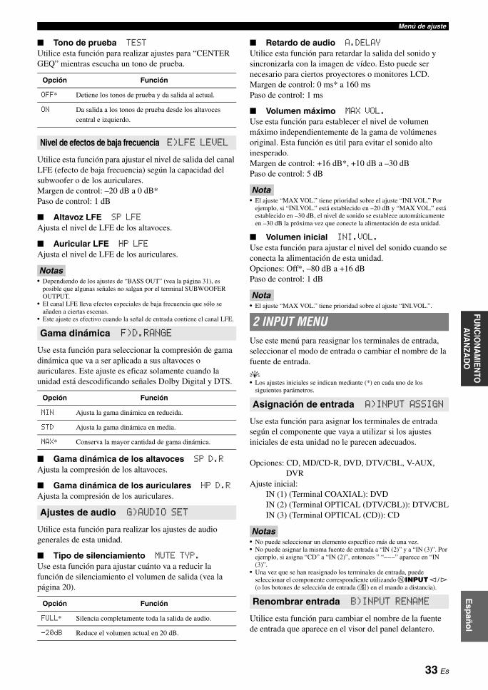
Menú de ajusteE
spañ
ol
INT
RO
DU
CC
IÓN
INF
OR
MA
CIÓ
N
AD
ICIO
NA
LA
PÉ
ND
ICE
PR
EPA
RA
CIÓ
NF
UN
CIO
NA
MIE
NTO
BÁ
SIC
OFU
NC
ION
AM
IENTO
AVA
NZA
DO
■ Tono de prueba TESTUtilice esta función para realizar ajustes para “CENTER GEQ” mientras escucha un tono de prueba.
Utilice esta función para ajustar el nivel de salida del canal LFE (efecto de baja frecuencia) según la capacidad del subwoofer o de los auriculares.Margen de control: –20 dB a 0 dB*Paso de control: 1 dB
■ Altavoz LFE SP LFEAjusta el nivel de LFE de los altavoces.
■ Auricular LFE HP LFEAjusta el nivel de LFE de los auriculares.
Notas• Dependiendo de los ajustes de “BASS OUT” (vea la página 31), es
posible que algunas señales no salgan por el terminal SUBWOOFER OUTPUT.
• El canal LFE lleva efectos especiales de baja frecuencia que sólo se añaden a ciertas escenas.
• Este ajuste es efectivo cuando la señal de entrada contiene el canal LFE.
Use esta función para seleccionar la compresión de gama dinámica que va a ser aplicada a sus altavoces o auriculares. Este ajuste es eficaz solamente cuando la unidad está descodificando señales Dolby Digital y DTS.
■ Gama dinámica de los altavoces SP D.RAjusta la compresión de los altavoces.
■ Gama dinámica de los auriculares HP D.RAjusta la compresión de los auriculares.
Utilice esta función para realizar los ajustes de audio generales de esta unidad.
■ Tipo de silenciamiento MUTE TYP.Use esta función para ajustar cuánto va a reducir la función de silenciamiento el volumen de salida (vea la página 20).
■ Retardo de audio A.DELAYUtilice esta función para retardar la salida del sonido y sincronizarla con la imagen de vídeo. Esto puede ser necesario para ciertos proyectores o monitores LCD.Margen de control: 0 ms* a 160 msPaso de control: 1 ms
■ Volumen máximo MAX VOL.Use esta función para establecer el nivel de volumen máximo independientemente de la gama de volúmenes original. Esta función es útil para evitar el sonido alto inesperado. Margen de control: +16 dB*, +10 dB a –30 dBPaso de control: 5 dB
Nota• El ajuste “MAX VOL.” tiene prioridad sobre el ajuste “INI.VOL.” Por
ejemplo, si “INI.VOL.” está establecido en –20 dB y “MAX VOL.” está establecido en –30 dB, el nivel de sonido se establece automáticamente en –30 dB la próxima vez que conecte la alimentación de esta unidad.
■ Volumen inicial INI.VOL.Use esta función para ajustar el nivel del sonido cuando se conecta la alimentación de esta unidad.Opciones: Off*, –80 dB a +16 dBPaso de control: 1 dB
Nota• El ajuste “MAX VOL.” tiene prioridad sobre el ajuste “INI.VOL.”.
Use este menú para reasignar los terminales de entrada, seleccionar el modo de entrada o cambiar el nombre de la fuente de entrada.
y• Los ajustes iniciales se indican mediante (*) en cada uno de los
siguientes parámetros.
Use esta función para asignar los terminales de entrada según el componente que vaya a utilizar si los ajustes iniciales de esta unidad no le parecen adecuados.
Opciones: CD, MD/CD-R, DVD, DTV/CBL, V-AUX, DVR
Ajuste inicial:IN (1) (Terminal COAXIAL): DVDIN (2) (Terminal OPTICAL (DTV/CBL)): DTV/CBLIN (3) (Terminal OPTICAL (CD)): CD
Notas• No puede seleccionar un elemento específico más de una vez.• No puede asignar la misma fuente de entrada a “IN (2)” y a “IN (3)”. Por
ejemplo, si asigna “CD” a “IN (2)”, entonces ” “–––” aparece en “IN (3)”.
• Una vez que se han reasignado los terminales de entrada, puede seleccionar el componente correspondiente utilizando NINPUT l / h (o los botones de selección de entrada (f) en el mando a distancia).
Utilice esta función para cambiar el nombre de la fuente de entrada que aparece en el visor del panel delantero.
Opción Función
OFF* Detiene los tonos de prueba y da salida al actual.
ON Da salida a los tonos de prueba desde los altavoces
central e izquierdo.
Nivel de efectos de baja frecuencia E)LFE LEVEL
Gama dinámica F)D.RANGE
Opción Función
MIN Ajusta la gama dinámica en reducida.
STD Ajusta la gama dinámica en media.
MAX* Conserva la mayor cantidad de gama dinámica.
Ajustes de audio G)AUDIO SET
Opción Función
FULL* Silencia completamente toda la salida de audio.
-20dB Reduce el volumen actual en 20 dB.
2 INPUT MENU
Asignación de entrada A)INPUT ASSIGN
Renombrar entrada B)INPUT RENAME
33 Es
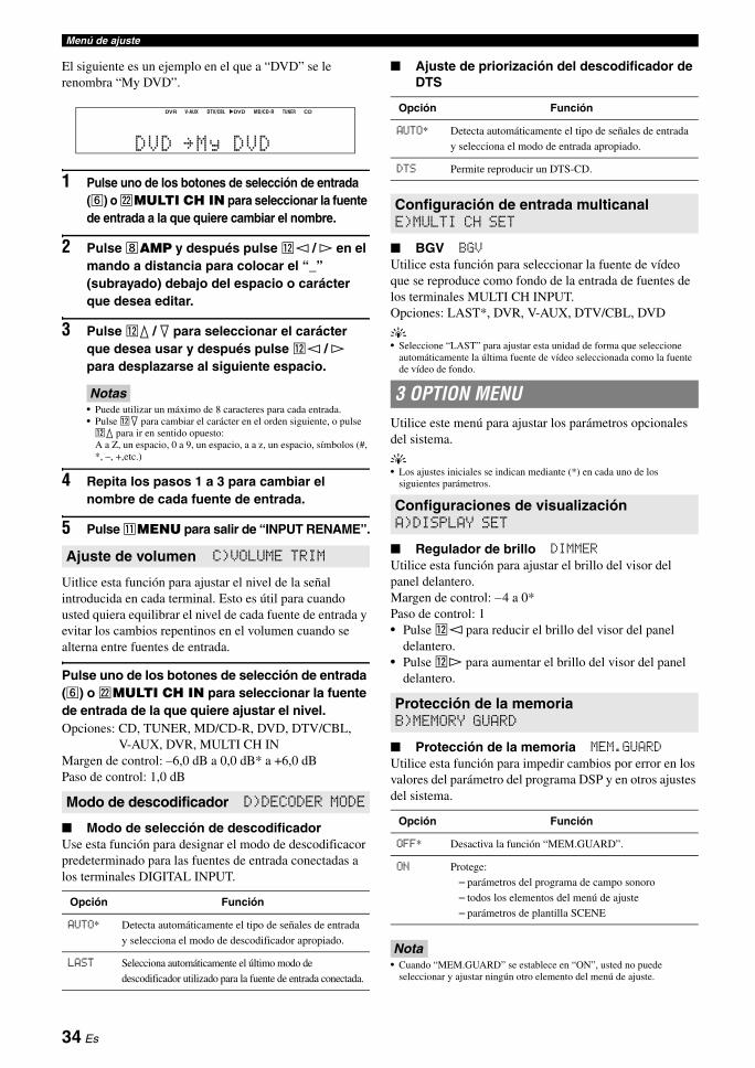
Menú de ajuste
El siguiente es un ejemplo en el que a “DVD” se le renombra “My DVD”.
1 Pulse uno de los botones de selección de entrada (f) o vMULTI CH IN para seleccionar la fuente de entrada a la que quiere cambiar el nombre.
2 Pulse hAMP y después pulse ll / h en el mando a distancia para colocar el “_” (subrayado) debajo del espacio o carácter que desea editar.
3 Pulse lk / n para seleccionar el carácter que desea usar y después pulse ll / h para desplazarse al siguiente espacio.
Notas• Puede utilizar un máximo de 8 caracteres para cada entrada.• Pulse ln para cambiar el carácter en el orden siguiente, o pulse lk para ir en sentido opuesto: A a Z, un espacio, 0 a 9, un espacio, a a z, un espacio, símbolos (#, *, –, +,etc.)
4 Repita los pasos 1 a 3 para cambiar el nombre de cada fuente de entrada.
5 Pulse kMENU para salir de “INPUT RENAME”.
Uitlice esta función para ajustar el nivel de la señal introducida en cada terminal. Esto es útil para cuando usted quiera equilibrar el nivel de cada fuente de entrada y evitar los cambios repentinos en el volumen cuando se alterna entre fuentes de entrada.
Pulse uno de los botones de selección de entrada (f) o vMULTI CH IN para seleccionar la fuente de entrada de la que quiere ajustar el nivel.Opciones: CD, TUNER, MD/CD-R, DVD, DTV/CBL,
V-AUX, DVR, MULTI CH INMargen de control: –6,0 dB a 0,0 dB* a +6,0 dBPaso de control: 1,0 dB
■ Modo de selección de descodificadorUse esta función para designar el modo de descodificacor predeterminado para las fuentes de entrada conectadas a los terminales DIGITAL INPUT.
■ Ajuste de priorización del descodificador de DTS
■ BGV BGVUtilice esta función para seleccionar la fuente de vídeo que se reproduce como fondo de la entrada de fuentes de los terminales MULTI CH INPUT.Opciones: LAST*, DVR, V-AUX, DTV/CBL, DVD
y• Seleccione “LAST” para ajustar esta unidad de forma que seleccione
automáticamente la última fuente de vídeo seleccionada como la fuente de vídeo de fondo.
Utilice este menú para ajustar los parámetros opcionales del sistema.
y• Los ajustes iniciales se indican mediante (*) en cada uno de los
siguientes parámetros.
■ Regulador de brillo DIMMERUtilice esta función para ajustar el brillo del visor del panel delantero.Margen de control: –4 a 0*Paso de control: 1• Pulse ll para reducir el brillo del visor del panel
delantero.• Pulse lh para aumentar el brillo del visor del panel
delantero.
■ Protección de la memoria MEM.GUARDUtilice esta función para impedir cambios por error en los valores del parámetro del programa DSP y en otros ajustes del sistema.
Nota• Cuando “MEM.GUARD” se establece en “ON”, usted no puede
seleccionar y ajustar ningún otro elemento del menú de ajuste.
Ajuste de volumen C)VOLUME TRIM
Modo de descodificador D)DECODER MODE
Opción Función
AUTO* Detecta automáticamente el tipo de señales de entrada
y selecciona el modo de descodificador apropiado.
LAST Selecciona automáticamente el último modo de
descodificador utilizado para la fuente de entrada conectada.
DVR pDVD CDV-AUX DTV/CBL MD/CD-R TUNER
DVD My DVD
Opción Función
AUTO* Detecta automáticamente el tipo de señales de entrada
y selecciona el modo de entrada apropiado.
DTS Permite reproducir un DTS-CD.
Configuración de entrada multicanal E)MULTI CH SET
3 OPTION MENU
Configuraciones de visualizaciónA)DISPLAY SET
Protección de la memoriaB)MEMORY GUARD
Opción Función
OFF* Desactiva la función “MEM.GUARD”.
ON Protege:
– parámetros del programa de campo sonoro
– todos los elementos del menú de ajuste
– parámetros de plantilla SCENE
34 Es

Menú de ajusteE
spañ
ol
INT
RO
DU
CC
IÓN
INF
OR
MA
CIÓ
N
AD
ICIO
NA
LA
PÉ
ND
ICE
PR
EPA
RA
CIÓ
NF
UN
CIO
NA
MIE
NTO
BÁ
SIC
OFU
NC
ION
AM
IENTO
AVA
NZA
DO
Use esta función para designar el ajuste de selección del terminal de entrada de audio para las fuentes de entrada.
Utilice esta función para establecer todos los parámetros de los programas de campo sonoro en los ajustes iniciales de fábrica.
Notas• No puede volver automáticamente a los ajustes del parámetro anterior
una vez que inicialice los parámetros del programa de campo sonoro.• No puede inicializar por separado programas de campo sonoro
individuales.
Selección de audio C)AUDIO SELECT
Opción Función
AUTO* Detecta automáticamente el tipo de señales de entrada
y selecciona el modo de entrada apropiado.
LAST Selecciona automáticamente el último modo de
entrada utilizado para la fuente de entrada conectada
(vea la página 19).
Inicialización de parámetrosD)PARAM. INI
Opción Función
NO* Cancela la inicialización de parámetros y regresa al
nivel de menú anterior.
YES Establece todos los parámetros de campo sonoro en los
ajustes iniciales de fábrica.
35 Es
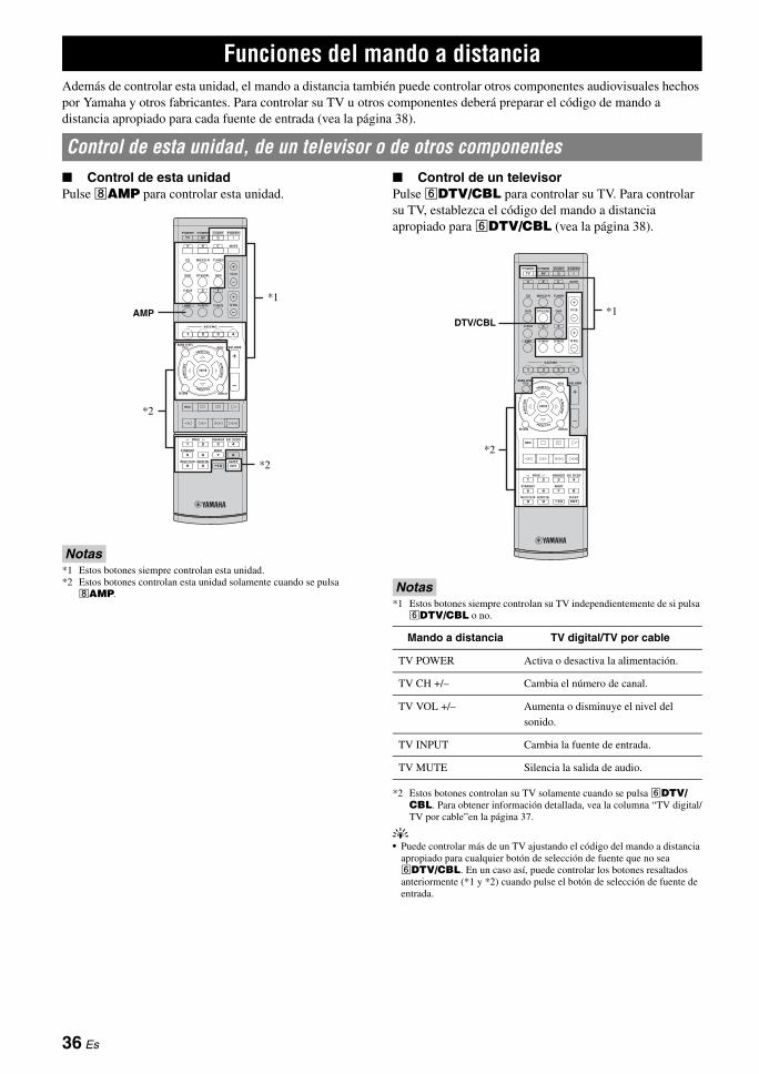
Además de controlar esta unidad, el mando a distancia también puede controlar otros componentes audiovisuales hechos por Yamaha y otros fabricantes. Para controlar su TV u otros componentes deberá preparar el código de mando a distancia apropiado para cada fuente de entrada (vea la página 38).-
■ Control de esta unidadPulse hAMP para controlar esta unidad.
Notas*1 Estos botones siempre controlan esta unidad.*2 Estos botones controlan esta unidad solamente cuando se pulsa hAMP.
■ Control de un televisorPulse fDTV/CBL para controlar su TV. Para controlar su TV, establezca el código del mando a distancia apropiado para fDTV/CBL (vea la página 38).
Notas*1 Estos botones siempre controlan su TV independientemente de si pulsa fDTV/CBL o no.
*2 Estos botones controlan su TV solamente cuando se pulsa fDTV/CBL. Para obtener información detallada, vea la columna “TV digital/TV por cable”en la página 37.
y• Puede controlar más de un TV ajustando el código del mando a distancia
apropiado para cualquier botón de selección de fuente que no sea fDTV/CBL. En un caso así, puede controlar los botones resaltados anteriormente (*1 y *2) cuando pulse el botón de selección de fuente de entrada.
Funciones del mando a distancia
Control de esta unidad, de un televisor o de otros componentes
REC
SUR. DECODE
NIGHTSTRAIGHT
MULTI CH IN AUDIO SEL SLEEP
ENHANCERl PROG h
TV MUTETV INPUT TV VOL
TV CH
POWER
AMP
STANDBYPOWER
MUTE
POWER
8
10
7
09
65
4321
ENT
DVD
V-AUX D E
DTV/CBL DVR
CD MD/CD-R TUNER
MENU VOLUMETITLE
ENTER
BAND LEVEL
DISPLAYRETURN
AVTV
SCENE
4321
A B C
AMP
*2
*1
*2
Mando a distancia TV digital/TV por cable
TV POWER Activa o desactiva la alimentación.
TV CH +/– Cambia el número de canal.
TV VOL +/– Aumenta o disminuye el nivel del
sonido.
TV INPUT Cambia la fuente de entrada.
TV MUTE Silencia la salida de audio.
REC
SUR. DECODE
NIGHTSTRAIGHT
MULTI CH IN AUDIO SEL SLEEP
ENHANCERl PROG h
TV MUTETV INPUT TV VOL
TV CH
POWER
AMP
STANDBYPOWER
MUTE
POWER
8
10
7
09
65
4321
ENT
DVD
V-AUX D E
DTV/CBL DVR
CD MD/CD-R TUNER
MENU VOLUMETITLE
ENTER
BAND LEVEL
DISPLAYRETURN
AVTV
SCENE
4321
A B C
DTV/CBL
*2
*1
36 Es
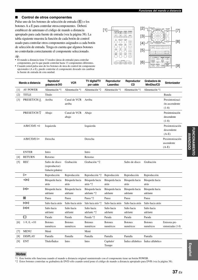
Funciones del mando a distanciaE
spañ
ol
INT
RO
DU
CC
IÓN
INF
OR
MA
CIÓ
N
AD
ICIO
NA
LA
PÉ
ND
ICE
PR
EPA
RA
CIÓ
NF
UN
CIO
NA
MIE
NTO
BÁ
SIC
OFU
NC
ION
AM
IENTO
AVA
NZA
DO
■ Control de otros componentesPulse uno de los botones de selección de entrada (f) o los botones A a E para controlar otros componentes. Deberá establecer de antemano el código de mando a distancia apropiado para cada fuente de entrada (vea la página 38). La tabla siguiente muestra la función de cada botón de control usado para controlar otros componentes asignados a cada botón de selección de entrada. Tenga en cuenta que algunos botones no controlarán correctamente el componente seleccionado.
y• El mando a distancia tiene 13 modos (áreas de entrada) para controlar
componentes, por lo que puede controlar hasta 13 componentes diferentes.• Cuando usted pulsa uno de los botones de área de control de componente
opcionales (A a E), puede controlar el componente deseado sin cambiar la fuente de entrada de esta unidad.
Notas*1 Este botón sólo funciona cuando el mando a distancia original suministrado con el componente tiene un botón POWER.*2 Estos botones controlan su grabadora de DVD sólo cuando usted pone el código de mando a distancia apropiado para DVR (vea la página 38).
TV MUTETV INPUT TV VOL
TV CH
POWER
AMP
STANDBYPOWER
MUTE
POWER
DVD
V-AUX D E
DTV/CBL DVR
CD MD/CD-R TUNER
AVTV
SCENE
4321
A B C
REC
SUR. DECODE
NIGHTSTRAIGHT
MULTI CH IN AUDIO SEL SLEEP
ENHANCERl PROG h
8
10
7
09
65
4321
ENT
MENU VOLUMETITLE
ENTER
BAND LEVEL
DISPLAYRETURN
[1] [2] [7]
[8]
[9]
[3]
[4]
[5]
[6]
Mando a distanciaReproductor/
grabadora de DVDVCR
TV digital/TV por cable
Reproductor Laserdisc
Reproductor CD
Grabadora de MiniDisc/CD
Sintonizador
[1] AV POWER Alimentación *1 Alimentación *1 Alimentación *2 Alimentación *1 Alimentación *1 Alimentación *1
[2] TITLE Título Banda
[3] PRESET/CH k Arriba Canal de VCR
arriba
Arriba Presintonizaci
ón ascendente
(1-8)
PRESET/CH n Abajo Canal de VCR
abajo
Abajo Presintonización
descendente
(1-8)
A/B/C/D/E l Izquierda Izquierda Presintonización
descendente
(A-E)
A/B/C/D/E h Derecha Derecha Presintonización
ascendente
(A-E)
ENTER Intro Intro
[4] RETURN Retorno Retorno
[5] REC Salto de disco
(reproductor)
Grabación (grabadora)
Grabación Grabación *2 Salto de disco Grabación
p Reproducción Reproducción Reproducción *2 Reproducción Reproducción Reproducción
w Búsqueda hacia
atrás
Búsqueda hacia
atrás
Búsqueda hacia
atrás *2
Búsqueda hacia
atrás
Búsqueda hacia
atrás
Búsqueda hacia
atrás
f Búsqueda hacia
adelante
Búsqueda hacia
adelante
Búsqueda hacia
adelante *2
Búsqueda hacia
adelante
Búsqueda hacia
adelante
Búsqueda hacia
adelante
e Pausa Pausa Pausa *2 Pausa Pausa Pausa
b Salto hacia atrás Salto hacia atrás Salto hacia atrás *2 Salto hacia atrás Salto hacia atrás Salto hacia atrás
a Salto hacia
adelante
Salto hacia
adelante
Salto hacia
adelante *2
Salto hacia
adelante
Salto hacia
adelante
Salto hacia
adelante
s Parada Parada Parada *2 Parada Parada Parada
[6] 1-9, 0, +10 Botones
numéricos
Botones
numéricos
Botones
numéricos
Botones
numéricos
Botones
numéricos
Botones
numéricos
Emisoras pre-
sintonizadas (1-8)
[7] MENU Menú Menú
[8] DISPLAY Pantalla Pantalla Pantalla Pantalla Pantalla Pantalla
[9] ENT Título/Índice Intro Intro Capítulo/
Tiempo
Índice alfabético Índice alfabético
37 Es

Funciones del mando a distancia
Estableciendo los códigos de mando a distancia apropiados puede controlar otros componentes. Para conocer una lista completa de códigos de mando a distancia disponibles, consulte “Lista de códigos de mando a distancia” al final de este manual.
Ajustes predeterminados de los códigos del mando a distancia
Nota• Tal vez no pueda controlar su componente Yamaha aunque se preajuste
un código de fabricante Yamaha listado arriba. En este caso, intente poner otros códigos de mando a distancia Yamaha.
1 Mientras pulsa y mantiene pulsado uno de los botones de selección de entrada (f) en el mando a distancia para seleccionar el área de entrada que desea ajustar, pulse bAV POWER durante más de 3 segundos.
2 Pulse los botones numéricos (0 a 9) (y) para introducir el código de mando a distancia de cuatro dígitos correspondiente al componentes que se va a utilizar.Cuando el ajuste tiene éxito, aparece “RemoteSetup OK”; sin embargo, cuando no tiene éxito, “RemoteSetup NG” aparece en el visor del panel delantero.
Notas• Si el fabricante de su componente tiene más de un código, intente con
cada uno de ellos hasta encontrar el correcto.• Si no pulsa ningún botón en el transcurso de 30 segundos en el paso 2, el
proceso de ajuste se cancela. Si ocurre esto, repita el procedimiento de ajuste.
■ Restablecimiento de todos los códigos del mando a distancia
Utilice esta función para borrar todos los códigos de mando a distancia previamente establecidos y restablecerlos todos a los ajustes iniciales de fábrica.
1 Mientras pulsa y mantiene pulsado hAMP, pulse bAV POWER durante más de 3 segundos.
2 Pulse los botones numéricos (y) para introducir el código numérico “9981”.Aparece “RemoteSetup OK” en el visor del panel delantero y se borran los códigos del mando a distancia previamente establecidos y se restablecen los ajustes iniciales de fábrica.
y• Si no pulsa ningún botón en el transcurso de 30 segundos después
del paso 1, el proceso de borrado se cancela. En este caso, repita el proceso de borrado.
Ajuste de los códigos de mando a distancia
Fuente de entrada
Categoría de componente
FabricanteCódigo
predeterminado
CD CD Yamaha 5013
MD/CD-R CD-R Yamaha 5001
TUNER TUNER Yamaha 5007
DVD DVD Yamaha 2000
DTV/CBL — — —
V-AUX TUNER Yamaha 5011
DVR DVR Yamaha 2011
A TUNER Yamaha 5012
B TUNER Yamaha 5009
C TUNER Yamaha 5017
D — — —
E — — —
DVD
V-AUX D E
DTV/CBL DVR
CD MD/CD-R TUNER
A B C
POWER
AV
Mientras se mantiene pulsado
Pulse durante 3 segundos
POWER
AV
AMP
Mientras se mantiene pulsado
Pulse durante 3 segundos
38 Es

Esp
año
lIN
TR
OD
UC
CIÓ
NIN
FO
RM
AC
IÓN
A
DIC
ION
AL
AP
ÉN
DIC
EP
RE
PAR
AC
IÓN
FU
NC
ION
AM
IEN
TO B
ÁS
ICO
FUN
CIO
NA
MIEN
TO
AVAN
ZAD
O
Esta unidad tiene menús adicionales que se visualizan en el visor del panel delantero. El menú de configuración avanzada ofrece operaciones adicionales para ajustar y personalizar la forma en que funciona esta unidad. Cambie los ajustes iniciales (indicados mediante (*) en este siguiente parámetro) para reflejar las necesidades de su ambiente de escucha.
Notas• Solamente ASTANDBY/ON, LPROGRAM l / h y MSTRAIGHT son eficaces mientras está utilizando el menú de configuración avanzada.
• Mientras usted está usando el menú de configuración avanzada no puede hacerse ninguna otra operación.
• El menú de configuración avanzada sólo está disponible en el visor del panel delantero.
1 Pulse ASTANDBY/ON en el visor del panel delantero para establecer esta unidad en el modo de espera.
2 Pulse y mantenga pulsado KTONE CONTROL y después pulse ASTANDBY/ON para encender esta unidad.Esta unidad se enciende y el menú de configuración avanzada aparece en el visor del panel delantero.
3 Pulse LPROGRAM l / h para seleccionar el parámetro que desea ajustar.El nombre del parámetro seleccionado aparece en el visor del panel delantero.
4 Pulse repetidamente MSTRAIGHT para modificar el ajuste del parámetro seleccionado.
5 Pulse ASTANDBY/ON para confirmar su selección y establecer esta unidad en el modo de espera.
y• Los ajustes que usted hace se reflejan la próxima vez que enciende esta
unidad.
■ Salto de frecuencia del sintonizador TU(únicamente modelos de Asia y General)
Use esta función para establecer el paso de frecuencias del sintonizador según la separación de frecuencias de su zona.Opciones: AM10/FM100*, AM9/FM50• Seleccione “AM10/FM100” para América del Norte,
Centroamérica y Sudamérica.• Seleccione “AM9/FM50” para todas las demás áreas.
■ Inicialización PRESETUtilice esta función para restablecer todos los parámetros de esta unidad a los ajustes iniciales de fábrica.Opciones: CANCEL*, RESET• Seleccione “CANCEL” para no restablecer ningún
parámetro de esta unidad.• Seleccione “RESET” para restablecer los parámetros de
esta unidad.
Nota• Los ajustes de fábrica iniciales se activarán la próxima vez que encienda
esta unidad.
Configuración avanzada
39 Es

INFORMACIÓN ADICIONAL
Consulte la tabla inferior cuando el equipo no funcione correctamente. Si el problema que usted tiene no aparece en la lista inferior o las instrucciones no le sirven de ayuda, apague esta unidad, desenchufe el cable de alimentación y póngase en contacto con un centro de servicio o concesionario Yamaha autorizado.
■ Generalidades
Resolución de problemas
Problema Causa RemedioVea la página
La unidad no se enciende o entra en el modo de espera poco después de conectar la alimentación.
El cable de alimentación no está conectado o
el enchufe no están bien insertado.
Conecte firmemente el cable de alimentación. —
Se ha activado el circuito de protección. Compruebe que todas las conexiones de los cables de
los altavoces de esta unidad y de todos los altavoces
estén bien realizadas, y que los cables de conexión no
tocan nada que no sean sus respectivas conexiones.
9
Esta unidad ha sido expuesta a una
descarga eléctrica externa intensa (rayo o
electricidad estática intensa).
Ponga esta unidad en el modo de espera, desconecte el
cable de alimentación, vuelva a conectarlo después de
30 segundos y luego utilice normalmente la unidad.
—
No hay sonido Conexión incorrecta de los cables de
entrada o salida.
Conecte correctamente los cables. Si el problema
persiste, los cables podrán estar defectuosos.
11-13
No se ha establecido una selección
apropiada del terminal de entrada de Audio.
Establezca una selección apropiada del terminal de
entrada de Audio.
35
No se ha seleccionado una fuente de
entrada apropiada.
Seleccione una fuente de entrada apropiada con NINPUT l / h del panel delantero (o los botones
de selección de entrada (f) del mando a distancia).
18, 19
Las conexiones de los altavoces no están seguras. Asegure las conexiones. 9
Los altavoces delanteros que se van a
utilizar no se han seleccionado
correctamente.
Seleccione los altavoces delanteros con
CSPEAKERS.
19
El volumen está bajo. Suba el volumen. —
El sonido está silenciado. Pulse eMUTE o mVOLUME +/– en el mando a
distancia para reanudar la salida de audio y luego
ajuste el volumen.
20
Existen señales que esta unidad no puede
reproducir y que se están introduciendo
desde un componente fuente, por ejemplo,
un CD-ROM.
Reproduzca una fuente cuyas señales pueda
reproducir esta unidad.
—
Las señales de audio introducidas en el
terminal HDMI no salen de ningún
terminal de altavoz.
Realice una conexión analógica o digital además de la
conexión HDMI.
—
El ajuste del componente conectado es
incorrecto.
Realice un ajuste apropiado siguiendo el manual de
instrucciones del componente conectado.
—
El sonido se apaga repentinamente.
El circuito de protección se ha activado
debido a un cortocircuito, etc.
Compruebe que los cables de los altavoces no se
tocan entre sí y encienda luego de nuevo esta unidad.
—
El temporizador para dormir ha apagado
esta unidad.
Encienda esta unidad y reproduzca de nuevo la fuente. —
El sonido está silenciado. Pulse eMUTE o mVOLUME +/– en el mando a
distancia para reanudar la salida de audio.
20
Sólo se escucha el sonido del altavoz de un lado.
Conexión incorrecta de los cables. Conecte correctamente los cables. Si el problema
persiste, los cables podrán estar defectuosos.
11-14
Ajustes incorrectos en “SP LEVEL”. Realice los ajustes de “SP LEVEL”. 32
40 Es

Resolución de problemasE
spañ
ol
INT
RO
DU
CC
IÓN
AP
ÉN
DIC
EP
RE
PAR
AC
IÓN
FU
NC
ION
AM
IEN
TO B
ÁS
ICO
FU
NC
ION
AM
IEN
TO A
VAN
ZA
DO
INF
OR
MA
CIÓ
N
AD
ICIO
NA
L
Sólo sale buen sonido por el altavoz central.
Cuando reproduce una fuente mono con
un programa CINEMA DSP, la señal de la
fuente se dirige al canal central y los
altavoces delanteros y surround dan salida
a los efectos de sonido.
No se oye sonido por el altavoz central.
“CENTER” en “SPEAKER SET” está
establecido en “NONE”.
Establezca “CENTER” en “SML” o “LRG”. 31
Algunos programas de campos sonoros no
dan salida a sonidos desde el altavoz central.
Pruebe con otro programa de campo sonoro. 26
No se oye sonido por los altavoces surround.
“SUR. LR” en “SPEAKER SET” está
establecido en “NONE”.
Establezca “SUR. LR” en “SML” o “LRG”. 31
Esta unidad está en el modo
“STRAIGHT” y se está reproduciendo
una fuente mono.
Pulse MSTRAIGHT en el panel delantero para que
“STRAIGHT” desaparezca del visor del panel delantero.
27
No hay sonido en el sub woofer.
“BASS OUT” en “SPEAKER SET” está
establecido en “FRONT” cuando se está
reproduciendo una señal de Dolby Digital
o DTS.
Establezca “BASS OUT” en “SWFR” o “BOTH”. 31
“BASS OUT” en “SPEAKER SET” está
establecido en “SWFR” o “FRONT” cuando
se está reproduciendo una fuente de 2
canales.
Establezca “BASS OUT” en “BOTH”. 31
La fuente no contiene señales de graves de
baja frecuencia.
No se pueden reproducir fuentes Dolby Digital o DTS. (El indicador Dolby Digital o DTS del visor del panel delantero no se enciende).
El componente conectado no está ajustado
para dar salida a las señales digitales
Dolby Digital o DTS.
Haga el ajuste apropiado siguiendo las instrucciones
de funcionamiento de su componente.
—
La selección del terminal de entrada de
audio está establecida en “ANALOG”.
Establezca la selección del terminal de entrada de
Audio en “AUTO”.
19
Se oye un sonido de zumbido.
Conexión incorrecta de los cables. Conecte firmemente los cables de audio. Si el problema
persiste, los cables podrán estar defectuosos.
—
No se puede incrementar el volumen del sonido o el sonido está distorsionado.
Usted está intentando ajustar el nivel de
sonido más que el nivel de sonido máximo.
Realice el ajuste de “MAX VOL”. 33
El componente conectado al terminal
AUDIO OUT (REC) de esta unidad está
apagado.
Conecte la alimentación del componente. —
El efecto de sonidos no se puede grabar.
No es posible grabar el efecto de sonidos
con un componente de grabación.
No se puede grabar una fuente mediante un componente analógico conectado al terminal AUDIO OUT (REC).
El componente fuente no está conectado a
los terminales AUDIO IN analógicos de
esta unidad.
Conecte el componente fuente a los terminales
AUDIO IN analógicos.
13
Los parámetros de campo sonoro y algunas otras configuraciones de este equipo no se pueden cambiar.
“MEM.GUARD” en “OPTION MENU”
está establecido en “ON”.
Establezca “MEM.GUARD” en “OFF”. 34
Problema Causa RemedioVea la página
41 Es
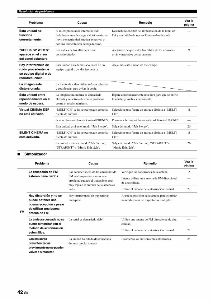
Resolución de problemas
■ Sintonizador
Esta unidad no funciona correctamente.
El microprocesador interno ha sido
dañado por una descarga eléctrica externa
(rayo o electricidad estática excesiva) o
por una alimentación de baja tensión.
Desenchufe el cable de alimentación de la toma de
CA y enchúfelo de nuevo 30 segundos después.
—
“CHECK SP WIRES” aparece en el visor del panel delantero.
Los cables de los altavoces están
cortocircuitados.
Asegúrese de que todos los cables de los altavoces
están conectados correctamente.
9
Hay interferencia de ruido procedente de un equipo digital o de radiofrecuencia.
Esta unidad está demasiado cerca de un
equipo digital o de alta frecuencia.
Aleje más esta unidad de ese equipo. —
La imagen está distorsionada.
La fuente de vídeo utiliza señales cifradas
y codificadas para evitar la copia.
Esta unidad entra repentinamente en el modo de espera.
La temperatura interna es demasiado
elevada y se activa el circuito protector
contra el recalentamiento.
Espere aproximadamente una hora para que se enfríe
la unidad y vuelva a encenderla.
—
Virtual CINEMA DSP no está activado.
“MULTI CH” se ha seleccionado como la
fuente de entrada.
Seleccione una fuente de entrada distinta a “MULTI
CH”.
18
Se conectan auriculares al terminal PHONES. Desconecte la clavija de los auriculares del terminal PHONES. —
Esta unidad está en el modo “5ch Stereo”. Salga del modo “5ch Stereo”. 26
SILENT CINEMA no está activado.
“MULTI CH” se ha seleccionado como la
fuente de entrada.
Seleccione una fuente de entrada distinta a “MULTI
CH”.
18
La unidad está en el modo “2ch Stereo”,
“STRAIGHT” o “Music Enh. 2ch”.
Salga del modo “2ch Stereo”, “STRAIGHT” o
“Music Enh. 2ch”.
26
Problema Causa RemedioVea la página
FM
La recepción de FM estéreo tiene ruidos.
Las características de las emisiones de
FM estéreo pueden causar este
problema cuando el transmisor está
muy lejos o la entrada de la antena es
mala.
Verifique las conexiones de la antena. 15
Intente utilizar una antena de FM direccional
de alta calidad.
—
Utilice el método de sintonización manual. 28
Hay distorsión y no se puede obtener una buena recepción a pesar de utilizar una buena antena de FM.
Hay interferencia de trayectorias
múltiples.
Ajuste la posición de la antena para eliminar
la interferencia de trayectorias multiples.
—
La emisora deseada no se puede sintonizar con el método de sintonización automática.
La señal es demasiado débil. Utilice una antena de FM direccional de alta
calidad.
—
Utilice el método de sintonización manual. 28
Las emisoras presintonizadas previamente no se pueden volver a sintonizar.
La unidad ha estado desconectada
durante mucho tiempo.
Establezca las emisoras presintonizadas. 28
Problema Causa RemedioVea la página
42 Es
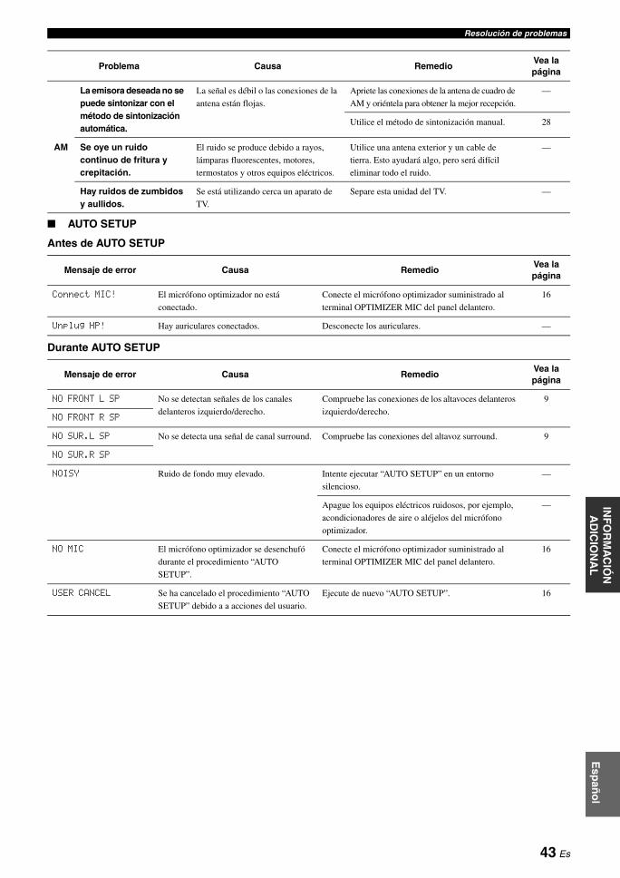
Resolución de problemasE
spañ
ol
INT
RO
DU
CC
IÓN
AP
ÉN
DIC
EP
RE
PAR
AC
IÓN
FU
NC
ION
AM
IEN
TO B
ÁS
ICO
FU
NC
ION
AM
IEN
TO A
VAN
ZA
DO
INF
OR
MA
CIÓ
N
AD
ICIO
NA
L
■ AUTO SETUP
Antes de AUTO SETUP
Durante AUTO SETUP
AM
La emisora deseada no se puede sintonizar con el método de sintonización automática.
La señal es débil o las conexiones de la
antena están flojas.
Apriete las conexiones de la antena de cuadro de
AM y oriéntela para obtener la mejor recepción.
—
Utilice el método de sintonización manual. 28
Se oye un ruido continuo de fritura y crepitación.
El ruido se produce debido a rayos,
lámparas fluorescentes, motores,
termostatos y otros equipos eléctricos.
Utilice una antena exterior y un cable de
tierra. Esto ayudará algo, pero será difícil
eliminar todo el ruido.
—
Hay ruidos de zumbidos y aullidos.
Se está utilizando cerca un aparato de
TV.
Separe esta unidad del TV. —
Mensaje de error Causa RemedioVea la página
Connect MIC! El micrófono optimizador no está
conectado.
Conecte el micrófono optimizador suministrado al
terminal OPTIMIZER MIC del panel delantero.
16
Unplug HP! Hay auriculares conectados. Desconecte los auriculares. —
Mensaje de error Causa RemedioVea la página
NO FRONT L SP No se detectan señales de los canales
delanteros izquierdo/derecho.
Compruebe las conexiones de los altavoces delanteros
izquierdo/derecho.
9
NO FRONT R SP
NO SUR.L SP No se detecta una señal de canal surround. Compruebe las conexiones del altavoz surround. 9
NO SUR.R SP
NOISY Ruido de fondo muy elevado. Intente ejecutar “AUTO SETUP” en un entorno
silencioso.
—
Apague los equipos eléctricos ruidosos, por ejemplo,
acondicionadores de aire o aléjelos del micrófono
optimizador.
—
NO MIC El micrófono optimizador se desenchufó
durante el procedimiento “AUTO
SETUP”.
Conecte el micrófono optimizador suministrado al
terminal OPTIMIZER MIC del panel delantero.
16
USER CANCEL Se ha cancelado el procedimiento “AUTO
SETUP” debido a a acciones del usuario.
Ejecute de nuevo “AUTO SETUP”. 16
Problema Causa RemedioVea la página
43 Es

Resolución de problemas
Después de AUTO SETUP
Notas• Si aparecen las pantallas “ERROR” o “WARNING”, compruebe la causa del problema y ejecute después de nuevo “AUTO SETUP”.• Si aparece un mensaje de advertencia “PHASE REVERSED”, se hacen correcciones, pero tal vez no sean óptimas.• Si aparece un mensaje de advertencia “DISTANCE ERROR” o “LEVEL ERROR”, no se hacen correcciones.
■ Mando a distancia
■ Reposición del sistemaUtilice esta función para restablecer todos los parámetros de esta unidad a los ajustes iniciales de fábrica. Para obtener información detallada sobre el procedimiento de reposición del sistema, vea “Inicialización” en “Configuración avanzada” en la página 39.
Mensaje de advertencia
Causa RemedioVea la página
PHASE REVERSED La polaridad de los altavoces no es la
correcta. Este mensaje puede aparecer
dependiendo de los altavoces aunque estos
estén correctamente conectados.
Compruebe que es correcta la polaridad de las
conexiones de los altavoces (+ o –).
9
DISTANCE ERROR La distancia entre el altavoz más cercano y
el más lejano está fuera de un margen
ajustable.
Acerque el altavoz a la posición de escucha. —
LEVEL ERROR Excesiva diferencia de nivel entre el
sonido de los altavoces. (No se realiza
corrección de nivel).
Si aparece “SWFR:TOO LOUD” o “SWFR:TOO
LOW”, ajuste el volumen de salida del subwoofer.
16
Reajuste la instalación de los atavoces para que todos
ellos estén en lugares con condiciones similares.
—
Verifique las conexiones de los altavoces. 9
Utilice altavoces de calidad similar. —
Problema Causa RemedioVea la página
El mando a distancia no funciona o funciona mal.
Distancia o ángulo erróneos. El mando a distancia funciona dentro de una distancia
de 6 m y sin exceder un ángulo de 30 grados a partir
del eje central del panel delantero.
8
La luz solar directa o de otras luces
(lámpara fluorescente tipo inversor, etc.)
cae directamente sobre el sensor de mando
a distancia de esta unidad.
Cambie la posición de esta unidad. —
Las pilas están casi agotadas. Cambie todas las pilas. 8
El código del mando a distancia no está
correctamente establecido.
Ponga correctamente el código del mando a distancia
utilizando la “Lista de códigos de mando a distancia”
al final de este manual.
38
Intente poner otro código del mismo fabricante
usando la “Lista de códigos de mando a distancia” al
final de este manual.
38
Aunque el código del mando a distancia esté
bien establecido, hay algunos modelos que
no responderán al mando a distancia.
44 Es
Esp
año
lIN
TR
OD
UC
CIÓ
NA
PÉ
ND
ICE
PR
EPA
RA
CIÓ
NF
UN
CIO
NA
MIE
NTO
BÁ
SIC
OF
UN
CIO
NA
MIE
NTO
AVA
NZ
AD
OIN
FO
RM
AC
IÓN
A
DIC
ION
AL
■ Información de audio
Dolby DigitalDolby Digital es un sistema de sonido surround digital que le proporciona un sonido de múltiples canales completamente independiente. Con 3 canales delanteros (delantero izquierdo/derecho y central) y 2 canales surround estéreo, Dolby Digital proporciona 5 canales de audio de gama completa. Con un canal adicional especial para efectos de graves, llamado LFE (efecto de baja frecuencia), el sistema tiene un total de 5.1 canales (LFE se cuenta como canal 0.1). Utilizando estéreo de 2 canales para los altavoces surround, es posible obtener efectos de sonido en movimiento y ambientes de sonido surround más precisos que con Dolby Surround. La amplia gama dinámica (desde el volumen máximo al mínimo) reproducida por los 5 canales de gama completa y la orientación precisa del sonido generada mediante procesamiento de sonido digital proporcionan al oyente una sensación y realismo nunca antes logrados. Con esta unidad, cualquier ambiente de sonido desde mono hasta la configuración de 5.1 canales se puede seleccionar libremente para disfrutar de él.
Dolby Pro Logic IIDolby Pro Logic II es una técnica mejorada utilizada para descodificar grandes cantidades de fuentes Dolby Surround existentes. Esta nueva tecnología permite realizar una reproducción discreta de 5 canales con 2 canales delanteros derecho e izquierdo, 1 canal central y 2 canales surround derecho e izquierdo en lugar de 1 solo canal surround para la tecnología Pro Logic convencional. Existen tres modos posibles: “Music mode” para fuentes de música, “Movie mode” para fuentes de películas y “Game mode” para fuentes de juegos.
Dolby SurroundDolby Surround utiliza un sistema de grabación analógica de 4 canales para reproducir efectos de sonido realistas y dinámicos: 2 canales delanteros derecho e izquierdo (estéreo), un canal central para el diálogo (mono) y un canal surround para efectos de sonido especiales (mono). El canal surround reproduce el sonido dentro de una gama de frecuencias estrecha. Dolby Surround se utiliza ampliamente con casi todas las cintas de vídeo y discos láser, y también en muchas emisiones de TV y de televisión por cable. El descodificador Dolby Pro Logic incorporado en esta unidad emplea un sistema de procesamiento de señales digitales que estabiliza automáticamente el volumen de cada canal para realzar los efectos y la direccionalidad del sonido en movimiento.
DTS Digital SurroundDTS digital surround fue desarrollado para reemplazar las pistas de sonido analógico de las películas por pistas de sonido digital de 5.1 canales, y actualmente está ganando una gran popularidad en los cines de todo el mundo. DTS, Inc. ha desarrollado un sistema de cine para casa con el que usted puede disfrutar la profundidad del sonido y la representación natural de surround digital DTS en su propia casa. Este sistema genera un sonido de 5.1 canales prácticamente sin distorsión (técnicamente, canales izquierdo, derecho y central, 2 canales surround, además de un canal 0.1 LFE como subwoofer, para un total de 5.1 canales).
Canal 0.1 LFEEste canal reproduce señales de graves de baja frecuencia. La gama de frecuencias de este canal es de 20 Hz a 120 Hz. Este canal se cuenta como 0.1 porque sólo impone una gama de bajas frecuencias en comparación con la gama completa reproducida por los otros 5 canales de los sistemas Dolby Digital o DTS de 5.1 canales.
PCM (Lineal PCM)Lineal PCM es un formato de señal bajo el cual una señal de audio analógico se digitaliza, se graba y se transmite sin utilizar ninguna compresión. Esto se utiliza como un método de grabación de CDs y DVD audio. El sistema PCM utiliza una técnica para realizar el muestreo del tamaño de la señal analógica por unidades de tiempo muy pequeñas. Siendo las siglas de “Pulse Code Modulation”, la señala analógica se codifica como impulsos y luego se modula para la grabación.
Frecuencia de muestreo y número de bits cuantificadosCuando se digitaliza una señal de audio analógico, el número de veces que se muestrea la señal por segundo recibe el nombre de frecuencia de muestreo, mientras que el grado de idoneidad cuando el nivel del sonido se convierte en valor numérico se llama bits cuantificados. La gama de frecuencias que se puede reproducir se determina mediante la frecuencia de muestreo, mientras que la gama dinámica que representa la diferencia del nivel del sonido se determina mediante el número de bits cuantificados. En principio, cuanto más alta es la frecuencia de muestreo, más amplia es la gama de frecuencias que puede reproducirse, y cuanto más alto es el número de bits cuantificados, más preciso es el nivel del sonido que puede reproducirse.
■ Información sobre los programas de campo sonoro
CINEMA DSPComo los sistemas Dolby Surround y DTS se diseñaron originalmente para ser utilizados en cines, su efecto se nota mejor en un cine con muchos altavoces diseñados para efectos acústicos. Como las condiciones de una casa, tales como el tamaño de la habitación, el material de las paredes, el número de altavoces, etc., pueden cambiar tanto, es inevitable que se produzcan también diferencias en el sonido. Basándose en una gran cantidad de datos medidos realmente, Yamaha CINEMA DSP utiliza la tecnología DSP original de Yamaha para combinar los sistemas Dolby Pro Logic, Dolby Digital y DTS con el fin de proporcionar la experiencia audiovisual del cine en la sala de escucha de su propio hogar.
SILENT CINEMAYamaha ha desarrollado un algoritmo DSP de efectos de sonido realistas y naturales para los auriculares. Se han establecido parámetros para los auriculares para cada programa de campo sonoro, de forma que se pueda disfrutar con auriculares de representaciones precisas de todos los programas de campo sonoro.
Virtual CINEMA DSPYamaha ha desarrollado un algoritmo Virtual CINEMA DSP, que le permite disfrutar, mediante el uso de altavoces surround virtuales, de los efectos surround DSP aunque no disponga de altavoces surround. Hasta se puede disfrutar de Virtual CINEMA DSP utilizando un sistema con un mínimo de dos altavoces sin altavoz central.
■ Información de vídeo
Señal de vídeo componenteCon el sistema de señal de vídeo componente, la señal de vídeo se separa en señal Y para la luminancia y señales PB y PR para la crominancia. El color se puede reproducir más fielmente con este sistema porque cada una de estas señales es independiente. La señal componente también se llama “señal de diferencia de color” porque la señal de luminancia se quita de la señal de color. Para dar salida a las señales de vídeo componente se necesita un monitor con terminales de entrada de vídeo componente.
Señal de vídeo compuestoCon el sistema de señal de vídeo compuesto, la señal de vídeo se compone de tres elementos básicos de imagen de vídeo: color, brillo y datos de sincronización. Un terminal de vídeo compuesto en un componente de vídeo trasmite estos tres elementos combinados.
Glosario
45 Es

SECCIÓN DE AUDIO
• Potencia de salida RMS mínima para los altavoces delanteros, central, surround
[Modelos de EE.UU. y Canadá]1 kHz, 0,9% THD, 8 Ω .......................................... 100 W/canal
[Otros modelos]1 kHz, 0,9% THD, 6 Ω .......................................... 100 W/canal
• Potencia máxima (JEITA)[Modelos de EE.UU. y Canadá]
1 kHz, 10% THD, 8 Ω ........................................... 135 W/canal[Modelos de Asia, China, Corea y General]
1 kHz, 10% THD, 6 Ω ............................................135 W/canal
• Potencia MÁX. por canal[Modelos de R.U., Rusia y Europa]
1 kHz, 0,7% THD, 4 Ω ......................................... 105 W o más
• Potencia IEC[Modelos de R.U., Rusia y Europa]
1 kHz, 0,1% THD, 6 Ω ........................................... 90 W o más
• Potencia dinámica[Modelos de EE.UU. y Canadá] (Selector de impedancia: 8 Ω)
(IHF, 8/6/4/2 Ω) .......................................... 110/130/160/180 W[Otros modelos]
(IHF, 6/4/2 Ω) .................................................... 105/130/150 W
• Techo dinámico [Modelos de EE.UU. y Canadá]8 Ω ..................................................................................... 0,41 dB
• Respuesta de frecuenciaCD, etc. a Parte delantera .................... 10 Hz a 100 kHz, 0/–3 dBV-AUX a Parte delantera ....................... 10 Hz a 20 kHz, 0/–3 dB
• Distorsión armónica totalCD, etc. (estéreo 2 canales) a Delantero SP OUT
[Modelos de EE.UU. y Canadá]1 kHz, 50 W/8 Ω ............................................... 0,06% o menos
[Otros modelos]1 kHz, 50 W/6 Ω ............................................... 0,06% o menos
• Relación señal a ruido (red IHF-A)CD, etc. (STEREO) Entrada en cortocircuito
250 mV................................................................... 100 dB o más200 mV..................................................................... 98 dB o más
• Ruido residual (red IHF-A)Parte delantera izquierda/derecha ....................... 170 µV o menos
• Separación de canales CD, etc. Entrada 5,1 kΩ en cortocircuito (1 kHz/10 kHz)
...................................................................... 60 dB/45 dB o más
• Control de tono Refuerzo/corte BASS ........................................... ±10 dB/100 HzRefuerzo/corte TREBLE ...................................... ±10 dB/20 kHz
• Impedancia/salida nominal del jack de auriculares CD, etc. (1 kHz, 200 mV, 8 Ω).................................... 0,4 V/470 Ω
• Sensibilidad de entrada/Impedancia de entradaCD, etc. .................................................................. 200 mV/47 kΩMULTI CH INPUT ............................................... 200 mV/47 kΩ
• Señal de entrada máximaCD, etc. 1 kHz, 0,5%THD (EFFECT ON) ................ 2,0 V o más
• Nivel de salida/Impedancia de salidaAUDIO OUT (REC) ............................................ 200 mV/1,2 kΩSUBWOOFER OUTPUT
(Estéreo de 2 canales y FRONT SP: SMALL) ........ 4 V/1,2 kΩ
• Características de filtro (fc=40/60/80/90/100/110/120/160/200 Hz)H.P.F. (Delantero, Central, Surround) ........................... 12 dB/oct.L.P.F. (Subwoofer) ........................................................ 24 dB/oct.
SECCIÓN DE VÍDEO
• Nivel de señalCompuesto ................................................................ 1 Vp-p/75 ΩComponente ................. 1 Vp-p/75 Ω (Y), 0,7 Vp-p/75 Ω (PB/PR)
• Nivel de entrada máximo de vídeo ........................... 1,5 Vp-p o más
• Relación señal a ruido ................................................... 50 dB o más
• Respuesta de frecuencia (MONITOR OUT)Señal componente ..................................... 5 Hz a 60 MHz, –3 dB
SECCIÓN DE FM
• Gama de sintonización[Modelos de EE.UU. y Canadá] ....................... 87,5 a 107,9 MHz[Modelos de Asia y General] ...... 87,5/87,50 a 108,0/108,00 MHz[Otros modelos] ............................................ 87,50 a 108,00 MHz
• Umbral de silenciamiento de 50 dB (IHF, 100% mod.)Mono ................................................................. 2,8 µV (20,2 dBf)
• Relación señal a ruido (IHF)Mono/estéreo ............................................................ 76 dB/70 dB
• Distorsión armónica (1 kHz)Mono/estéreo ............................................................... 0,5%/0,5%
SECCIÓN DE AM
• Gama de sintonización[Modelos de EE.UU. y Canadá] .......................... 530 a 1710 kHz[Modelos de Asia y General] ............... 530/531 a 1710/1611 kHz[Otros modelos] ................................................... 531 a 1611 kHz
GENERALIDADES
• Alimentación[Modelos de EE.UU. y Canadá] ........................ CA 120 V, 60 Hz[Modelo de Australia] ........................................ CA 240 V, 50 Hz[Modelo de Corea] ............................................. CA 220 V, 60 Hz[Modelo de China] ............................................. CA 220 V, 50 Hz[Modelos de R.U., Rusia y Europa] .................... CA 230 V, 50 Hz[Modelos de Asia y General]
............................................. CA 110–120/220–240 V, 50/60 Hz
• Consumo[Modelos de EE.UU. y Canadá] ..............................240 W/320 VA[Otros modelos] .................................................................. 240 W
• Consumo en espera[Excepto Asia y General] .................................................... 0,8 W
• Consumo máximo[Modelos de Asia y General]
5 canales, 10%/THD ........................................................ 530 WDimensiones (An x Al x Prof)....................... 435 x 151 x 318 mm
• Peso ......................................................................................... 8,0 kg
* Las especificaciones están sujetas a cambios sin previo aviso.
Especificaciones
46 Es
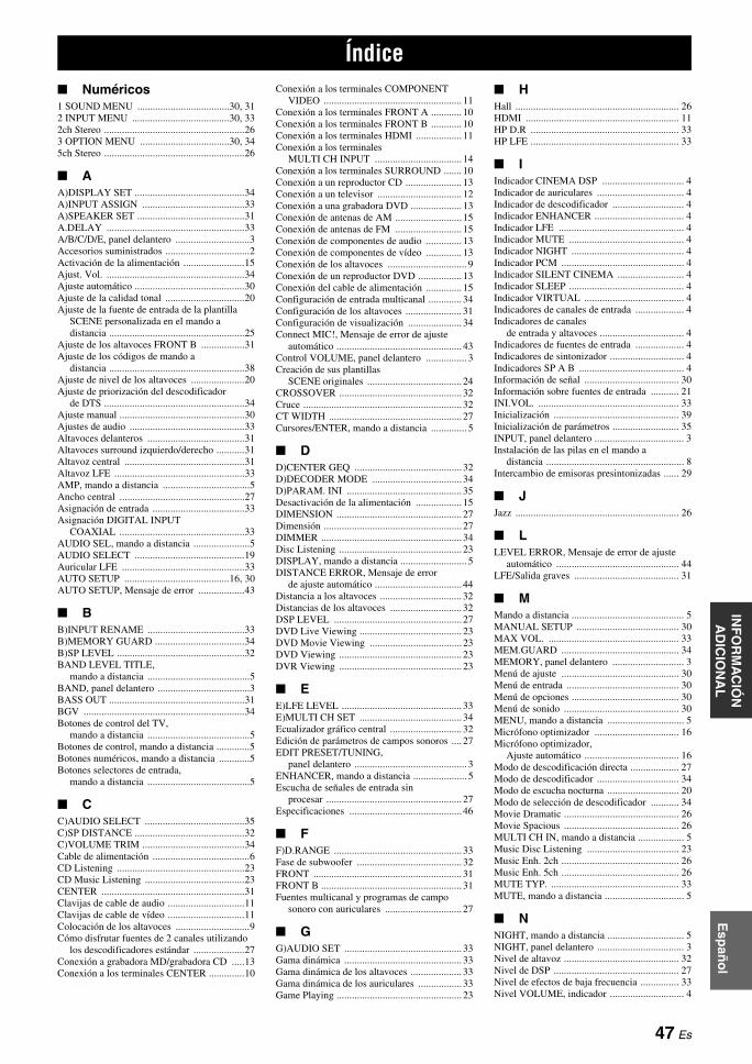
Esp
año
lIN
FO
RM
AC
IÓN
A
DIC
ION
AL
■ Numéricos1 SOUND MENU ....................................30, 312 INPUT MENU ......................................30, 332ch Stereo .......................................................263 OPTION MENU ...................................30, 345ch Stereo .......................................................26
■ AA)DISPLAY SET ...........................................34A)INPUT ASSIGN ........................................33A)SPEAKER SET ..........................................31A.DELAY ......................................................33A/B/C/D/E, panel delantero .............................3Accesorios suministrados .................................2Activación de la alimentación ........................15Ajust. Vol. ......................................................34Ajuste automático ...........................................30Ajuste de la calidad tonal ...............................20Ajuste de la fuente de entrada de la plantilla
SCENE personalizada en el mando a distancia .....................................................25
Ajuste de los altavoces FRONT B .................31Ajuste de los códigos de mando a
distancia .....................................................38Ajuste de nivel de los altavoces .....................20Ajuste de priorización del descodificador
de DTS .......................................................34Ajuste manual .................................................30Ajustes de audio .............................................33Altavoces delanteros ......................................31Altavoces surround izquierdo/derecho ...........31Altavoz central ...............................................31Altavoz LFE ...................................................33AMP, mando a distancia ..................................5Ancho central .................................................27Asignación de entrada ....................................33Asignación DIGITAL INPUT
COAXIAL .................................................33AUDIO SEL, mando a distancia ......................5AUDIO SELECT ...........................................19Auricular LFE ................................................33AUTO SETUP .........................................16, 30AUTO SETUP, Mensaje de error ..................43
■ BB)INPUT RENAME ......................................33B)MEMORY GUARD ...................................34B)SP LEVEL ..................................................32BAND LEVEL TITLE,
mando a distancia ........................................5BAND, panel delantero ....................................3BASS OUT .....................................................31BGV ...............................................................34Botones de control del TV,
mando a distancia ........................................5Botones de control, mando a distancia .............5Botones numéricos, mando a distancia ............5Botones selectores de entrada,
mando a distancia ........................................5
■ CC)AUDIO SELECT .......................................35C)SP DISTANCE ...........................................32C)VOLUME TRIM ........................................34Cable de alimentación ......................................6CD Listening ..................................................23CD Music Listening .......................................23CENTER ........................................................31Clavijas de cable de audio ..............................11Clavijas de cable de vídeo ..............................11Colocación de los altavoces .............................9Cómo disfrutar fuentes de 2 canales utilizando
los descodificadores estándar ....................27Conexión a grabadora MD/grabadora CD .....13Conexión a los terminales CENTER ..............10
Conexión a los terminales COMPONENT VIDEO ...................................................... 11
Conexión a los terminales FRONT A ............ 10Conexión a los terminales FRONT B ............ 10Conexión a los terminales HDMI .................. 11Conexión a los terminales
MULTI CH INPUT .................................. 14Conexión a los terminales SURROUND ....... 10Conexión a un reproductor CD ...................... 13Conexión a un televisor ................................. 12Conexión a una grabadora DVD .................... 13Conexión de antenas de AM .......................... 15Conexión de antenas de FM .......................... 15Conexión de componentes de audio .............. 13Conexión de componentes de vídeo .............. 13Conexión de los altavoces ............................... 9Conexión de un reproductor DVD ................. 13Conexión del cable de alimentación .............. 15Configuración de entrada multicanal ............. 34Configuración de los altavoces ...................... 31Configuración de visualización ..................... 34Connect MIC!, Mensaje de error de ajuste
automático ................................................. 43Control VOLUME, panel delantero ................ 3Creación de sus plantillas
SCENE originales ..................................... 24CROSSOVER ................................................ 32Cruce .............................................................. 32CT WIDTH .................................................... 27Cursores/ENTER, mando a distancia .............. 5
■ DD)CENTER GEQ .......................................... 32D)DECODER MODE ................................... 34D)PARAM. INI ............................................. 35Desactivación de la alimentación .................. 15DIMENSION ................................................. 27Dimensión ...................................................... 27DIMMER ....................................................... 34Disc Listening ................................................ 23DISPLAY, mando a distancia .......................... 5DISTANCE ERROR, Mensaje de error
de ajuste automático .................................. 44Distancia a los altavoces ................................ 32Distancias de los altavoces ............................ 32DSP LEVEL .................................................. 27DVD Live Viewing ........................................ 23DVD Movie Viewing .................................... 23DVD Viewing ................................................ 23DVR Viewing ................................................ 23
■ EE)LFE LEVEL ............................................... 33E)MULTI CH SET ........................................ 34Ecualizador gráfico central ............................ 32Edición de parámetros de campos sonoros .... 27EDIT PRESET/TUNING,
panel delantero ............................................ 3ENHANCER, mando a distancia ..................... 5Escucha de señales de entrada sin
procesar ..................................................... 27Especificaciones ............................................ 46
■ FF)D.RANGE .................................................. 33Fase de subwoofer ......................................... 32FRONT .......................................................... 31FRONT B ....................................................... 31Fuentes multicanal y programas de campo
sonoro con auriculares .............................. 27
■ GG)AUDIO SET .............................................. 33Gama dinámica .............................................. 33Gama dinámica de los altavoces .................... 33Gama dinámica de los auriculares ................. 33Game Playing ................................................. 23
■ HHall ................................................................ 26HDMI ............................................................ 11HP D.R .......................................................... 33HP LFE .......................................................... 33
■ IIndicador CINEMA DSP ................................ 4Indicador de auriculares .................................. 4Indicador de descodificador ............................ 4Indicador ENHANCER ................................... 4Indicador LFE ................................................. 4Indicador MUTE ............................................. 4Indicador NIGHT ............................................ 4Indicador PCM ................................................ 4Indicador SILENT CINEMA .......................... 4Indicador SLEEP ............................................. 4Indicador VIRTUAL ....................................... 4Indicadores de canales de entrada ................... 4Indicadores de canales
de entrada y altavoces ................................. 4Indicadores de fuentes de entrada ................... 4Indicadores de sintonizador ............................. 4Indicadores SP A B ......................................... 4Información de señal ..................................... 30Información sobre fuentes de entrada ........... 21INI.VOL. ....................................................... 33Inicialización ................................................. 39Inicialización de parámetros .......................... 35INPUT, panel delantero ................................... 3Instalación de las pilas en el mando a
distancia ...................................................... 8Intercambio de emisoras presintonizadas ...... 29
■ JJazz ................................................................ 26
■ LLEVEL ERROR, Mensaje de error de ajuste
automático ................................................ 44LFE/Salida graves ......................................... 31
■ MMando a distancia ............................................ 5MANUAL SETUP ........................................ 30MAX VOL. ................................................... 33MEM.GUARD .............................................. 34MEMORY, panel delantero ............................ 3Menú de ajuste .............................................. 30Menú de entrada ............................................ 30Menú de opciones .......................................... 30Menú de sonido ............................................. 30MENU, mando a distancia .............................. 5Micrófono optimizador ................................. 16Micrófono optimizador,
Ajuste automático ..................................... 16Modo de descodificación directa ................... 27Modo de descodificador ................................ 34Modo de escucha nocturna ............................ 20Modo de selección de descodificador ........... 34Movie Dramatic ............................................. 26Movie Spacious ............................................. 26MULTI CH IN, mando a distancia .................. 5Music Disc Listening .................................... 23Music Enh. 2ch .............................................. 26Music Enh. 5ch .............................................. 26MUTE TYP. .................................................. 33MUTE, mando a distancia ............................... 5
■ NNIGHT, mando a distancia .............................. 5NIGHT, panel delantero .................................. 3Nivel de altavoz ............................................. 32Nivel de DSP ................................................. 27Nivel de efectos de baja frecuencia ............... 33Nivel VOLUME, indicador ............................. 4
Índice
47 Es
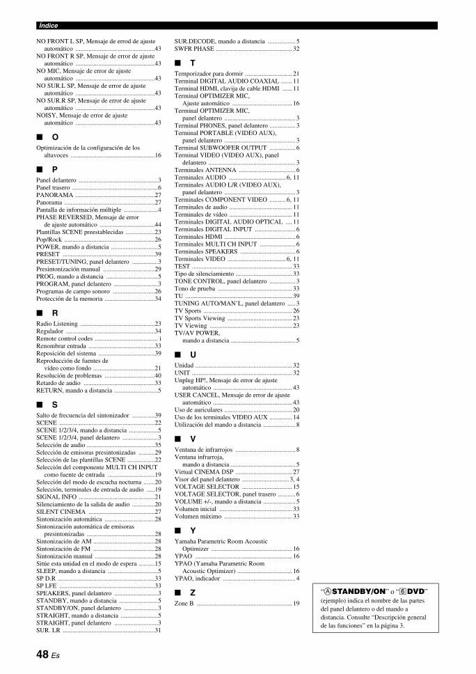
Índice
NO FRONT L SP, Mensaje de errod de ajuste automático .................................................43
NO FRONT R SP, Mensaje de error de ajuste automático .................................................43
NO MIC, Mensaje de error de ajuste automático .................................................43
NO SUR.L SP, Mensaje de error de ajuste automático .................................................43
NO SUR.R SP, Mensaje de error de ajuste automático .................................................43
NOISY, Mensaje de error de ajuste automático .................................................43
■ OOptimización de la configuración de los
altavoces ....................................................16
■ PPanel delantero .................................................3Panel trasero .....................................................6PANORAMA .................................................27Panorama ........................................................27Pantalla de información múltiple .....................4PHASE REVERSED, Mensaje de error
de ajuste automático ..................................44Plantillas SCENE preestablecidas ..................23Pop/Rock ........................................................26POWER, mando a distancia .............................5PRESET .........................................................39PRESET/TUNING, panel delantero ................3Presintonización manual ................................29PROG, mando a distancia ................................5PROGRAM, panel delantero ...........................3Programas de campo sonoro ..........................26Protección de la memoria ...............................34
■ RRadio Listening ..............................................23Regulador .......................................................34Remote control codes ....................................... iRenombrar entrada .........................................33Reposición del sistema ...................................39Reproducción de fuentes de
vídeo como fondo ......................................21Resolución de problemas ...............................40Retardo de audio ............................................33RETURN, mando a distancia ...........................5
■ SSalto de frecuencia del sintonizador ..............39SCENE ...........................................................22SCENE 1/2/3/4, mando a distancia ..................5SCENE 1/2/3/4, panel delantero ......................3Selección de audio ..........................................35Selección de emisoras presintonizadas ..........29Selección de las plantillas SCENE .................22Selección del componente MULTI CH INPUT
como fuente de entrada .............................19Selección del modo de escucha nocturna .......20Selección, terminales de entrada de audio .....19SIGNAL INFO ...............................................21Silenciamiento de la salida de audio ..............20SILENT CINEMA .........................................27Sintonización automática ...............................28Sintonización automática de emisoras
presintonizadas ..........................................28Sintonización de AM ......................................28Sintonización de FM ......................................28Sintonización manual .....................................28Sitúe esta unidad en el modo de espera ..........15SLEEP, mando a distancia ...............................5SP D.R ............................................................33SP LFE ...........................................................33SPEAKERS, panel delantero ...........................3STANDBY, mando a distancia ........................5STANDBY/ON, panel delantero .....................3STRAIGHT, mando a distancia .......................5STRAIGHT, panel delantero ...........................3SUR. LR .........................................................31
SUR.DECODE, mando a distancia ................. 5SWFR PHASE ............................................... 32
■ TTemporizador para dormir ............................. 21Terminal DIGITAL AUDIO COAXIAL ....... 11Terminal HDMI, clavija de cable HDMI ...... 11Terminal OPTIMIZER MIC,
Ajuste automático ..................................... 16Terminal OPTIMIZER MIC,
panel delantero ............................................ 3Terminal PHONES, panel delantero ................ 3Terminal PORTABLE (VIDEO AUX),
panel delantero ............................................ 3Terminal SUBWOOFER OUTPUT ................ 6Terminal VIDEO (VIDEO AUX), panel
delantero ...................................................... 3Terminales ANTENNA ................................... 6Terminales AUDIO ................................... 6, 11Terminales AUDIO L/R (VIDEO AUX),
panel delantero ............................................ 3Terminales COMPONENT VIDEO .......... 6, 11Terminales de audio ....................................... 11Terminales de vídeo ....................................... 11Terminales DIGITAL AUDIO OPTICAL .... 11Terminales DIGITAL INPUT ......................... 6Terminales HDMI ............................................ 6Terminales MULTI CH INPUT ...................... 6Terminales SPEAKERS .................................. 6Terminales VIDEO .................................... 6, 11TEST .............................................................. 33Tipo de silenciamiento ................................... 33TONE CONTROL, panel delantero ................ 3Tono de prueba .............................................. 33TU .................................................................. 39TUNING AUTO/MAN’L, panel delantero ..... 3TV Sports ....................................................... 26TV Sports Viewing ........................................ 23TV Viewing ................................................... 23TV/AV POWER,
mando a distancia ........................................ 5
■ UUnidad ............................................................ 32UNIT .............................................................. 32Unplug HP!, Mensaje de error de ajuste
automático ................................................. 43USER CANCEL, Mensaje de error de ajuste
automático ................................................. 43Uso de auriculares .......................................... 20Uso de los terminales VIDEO AUX .............. 14Utilización del mando a distancia .................... 8
■ VVentana de infrarrojos ..................................... 8Ventana infrarroja,
mando a distancia ........................................ 5Virtual CINEMA DSP ................................... 27Visor del panel delantero ............................. 3, 4VOLTAGE SELECTOR ............................... 15VOLTAGE SELECTOR, panel trasero ........... 6VOLUME +/-, mando a distancia .................... 5Volumen inicial ............................................. 33Volumen máximo .......................................... 33
■ YYamaha Parametric Room Acoustic
Optimizer .................................................. 16YPAO ............................................................ 16YPAO (Yamaha Parametric Room
Acoustic Optimizer) .................................. 16YPAO, indicador ............................................. 4
■ ZZone B ........................................................... 19
“ASTANDBY/ON” o “fDVD” (ejemplo) indica el nombre de las partes del panel delantero o del mando a distancia. Consulte “Descripción general de las funciones” en la página 3.
48 Es

AP
PE
ND
IX
List of remote control codesLista de códigos de mando a distancia
Blu-ray PlayerSamsung 2137
CD PlayerYamaha 5000, 5013
CD RecorderYamaha 5001
DVDAcoustic Solutions
2078Aiwa 2055, 2100Akai 2096Akura 2076Alba 2078, 2086Apex 2027, 2049Awa 2078Axion 2078Brainwave 2096Brandt 2073, 2085Broksonic 2060Bush 2075, 2078, 2112Centrex 2077Classic 2078Clatronic 2075Coby 2078C-Tech 2074CyberHome 2025, 2079, 2091Daewoo 2092, 2098Dansai 2096Daytek 2080, 2089DEC 2075Denon 2030, 2102, 2103Denver 2075, 2076Diamond 2074DK Digital 2094Dual 2078D-Vision 2096DVX 2074Elta 2096Euroline 2096Funai 2052, 2058Global Solutions2074Global Sphere 2074Goodmans 2075, 2077, 2078Grundig 2077, 2098H&B 2075Haaz 2074HE 2078Hitachi 2032, 2072Home Electronics
2078Innovation 2072Irradio 2134JDB 2078JVC 2033, 2045, 2053,
2073, 2099Kenwood 2030, 2097Kingavon 2075Koda 2075Lawson 2074Lenco 2075LG 2084, 2087Lifetec 2072Limit 2074LogicLab 2074Luxor 2077Magnavox 2037, 2073, 2075Magnum 2072MBO 2078Medion 2072Micromaxx 2072Micromedia 2073Microstar 2072Mitsubishi 2035Mizuda 2075Mustek 2078Naiko 2077Onkyo 2073, 2135Orava 2075P&B 2075
Pacific 2074Panasonic 2030, 2040, 2054,
2057, 2105, 2110Philips 2019, 2026, 2046,
2073, 2081, 2090Pioneer 2036, 2082Proline 2077Provision 2075RCA 2031, 2042, 2050,
2051Red Star 2076Reoc 2074Roadstar 2075, 2078, 2086Rowa 2077Saba 2085Sabaki 2074Samsung 2032, 2041, 2104,
2113Sansui 2074Sanyo 2095ScanMagic 2078Scientific Labs 2074Scott 2088SEG 2074, 2086Sharp 2034, 2043, 2059,
2093, 2106Silva 2076Singer 2074Skymaster 2074, 2078Skyworth 2076SM Electronic 2074, 2078Sony 2028, 2029, 2039,
2083, 2107Soundmaster 2074Soundmax 2074Standard 2074Star Cluster 2074Starmedia 2075Supervision 2074, 2078Sylvania 2052, 2058Synn 2074TCM 2072Teac 2074Tec 2076Technics 2030Technika 2096Technosonic 2096Tevion 2072, 2074Thomson 2085, 2109Tokai 2076Toshiba 2026, 2044, 2048,
2056, 2073, 2108, 2111
United 2078Voxson 2078Wharfedale 2074Xlogic 2074Yakumo 2077Yamada 2077Yamaha 2000, 2001, 2003,
2030, 2101Yukai 2078Zenith 2038, 2047, 2073
DVD RecorderApex 2024JVC 2070LG 2071Panasonic 2020, 2065, 2066,
2067Philips 2019, 2061, 2062,
2063Pioneer 2021RCA 2018Sony 2022, 2064Toshiba 2068Yamaha 2023Yukai 2069
DVD/LDPioneer 2036
DVD/VCRJVC 1017, 2045LG 1071, 2087Panasonic 1020, 1072, 2040,
2105Philips 1025RCA 1022, 2042Samsung 1021, 2041, 2104Sharp 1023, 1073, 2043,
2106Sony 1019, 1074, 2039,
2107Toshiba 1024, 1075, 2044,
2108Zenith 1026, 2047
DVD/DVRPanasonic 2067Pioneer 2114Samsung 2115Toshiba 2068
DVRABS 2132Alienware 2132CyberPower 2132Dell 2132DIRECTV 2123, 2128, 2129,
2133DISH Network 2126, 2127Dishpro 2126Echostar 2126, 2127Expressvu 2126Gateway 2132GOI 2126Hewlett Packard 2132Hitachi 2008Howard Computers
2132HTS 2126Hughes 2123, 2128Humax 2123Hush 2132iBUYPOWER 2132JVC 2126, 2127Linksys 2132Media Center PC
2132Microsoft 2132Mind 2132Niveus Media 2132Northgate 2132Panasonic 2015, 2016, 2017,
2120Philips 2117, 2121, 2123,
2128Pioneer 2012, 2013, 2014Proscan 2129RCA 2116, 2124, 2129,
2133ReplayTV 2118, 2119, 2120Sharp 2009, 2010Sonic Blue 2119, 2120Sony 2005, 2006, 2007,
2122, 2130, 2131, 2132
Stack 10 2132Stack 9 2132Systemax 2132Tagar Systems 2132Tivo 2116, 2121, 2122,
2123, 2130, 2131Toshiba 2004, 2125, 2132Touch 2132UltimateTV 2133Viewsonic 2132Voodoo 2132Yamaha 2011ZT Group 2132
HD DVDToshiba 2136
iPodYamaha 5011
LD PlayerYamaha 2002
MDYamaha 5002, 5003, 5004
Tape DeckYamaha 5005, 5006
TunerYamaha 5007, 5008, 5009,
5010, 5012, 5014, 5015, 5016, 5017, 5018
TVAcer 0093Acme 0207Acura 0208ADA 0255ADC 0206Admiral 0058, 0205, 0206,
0210, 0211Adyson 0200, 0207Agashi 0200Agazi 0206AGB 0204Aiko 0127, 0200, 0207,
0208Aiwa 0028, 0139, 0229,
0237Akai 0059, 0065, 0127,
0129, 0130, 0200, 0204, 0208, 0209, 0213, 0217, 0218, 0255
Akiba 0209, 0218Akura 0206, 0209, 0218Alaron 0200Alba 0200, 0207, 0208,
0209, 0217, 0218ALBIRAL 0212Allstar 0213Amplivision 0207Amstrad 0204, 0206, 0208,
0209, 0218Amtron 0062Anam 0208Anam National 0062Anglo 0208Anitech 0206, 0208Ansonic 0203, 0208AOC 0060, 0061Apex 0118, 0122, 0132Arc en Ciel 0216Arcam 0200Arcam Delta 0207Aristona 0213, 0217ASA 0205, 0211Asberg 0213Astra 0208Asuka 0200, 0206, 0207,
0209, 0218Atlantic 0200, 0207, 0213,
0217Atori 0208Audiosonic 0207, 0208, 0209,
0213, 0216, 0217, 0218
AudioTon 0207Audiovox 0062Autovox 0205, 0206, 0207Awa 0200Baird 0216Bang & Olufsen 0205Basic Line 0208, 0209, 0213,
0218Bastide 0207
i
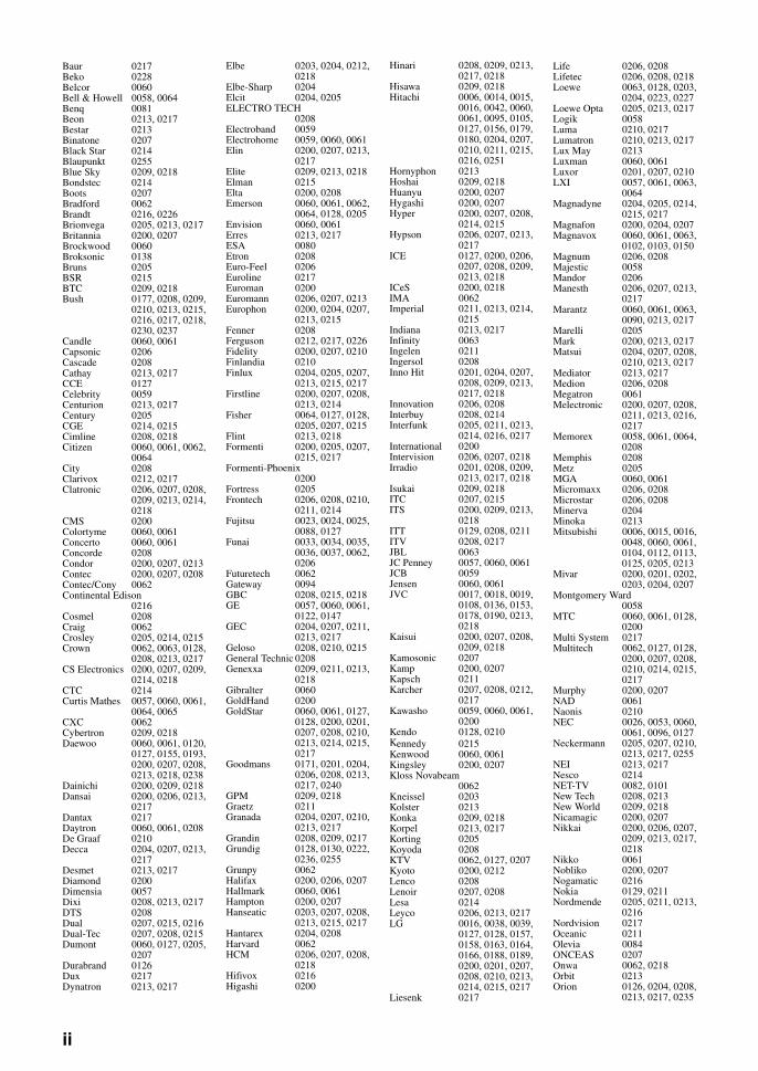
Baur 0217Beko 0228Belcor 0060Bell & Howell 0058, 0064Benq 0081Beon 0213, 0217Bestar 0213Binatone 0207Black Star 0214Blaupunkt 0255Blue Sky 0209, 0218Bondstec 0214Boots 0207Bradford 0062Brandt 0216, 0226Brionvega 0205, 0213, 0217Britannia 0200, 0207Brockwood 0060Broksonic 0138Bruns 0205BSR 0215BTC 0209, 0218Bush 0177, 0208, 0209,
0210, 0213, 0215, 0216, 0217, 0218, 0230, 0237
Candle 0060, 0061Capsonic 0206Cascade 0208Cathay 0213, 0217CCE 0127Celebrity 0059Centurion 0213, 0217Century 0205CGE 0214, 0215Cimline 0208, 0218Citizen 0060, 0061, 0062,
0064City 0208Clarivox 0212, 0217Clatronic 0206, 0207, 0208,
0209, 0213, 0214, 0218
CMS 0200Colortyme 0060, 0061Concerto 0060, 0061Concorde 0208Condor 0200, 0207, 0213Contec 0200, 0207, 0208Contec/Cony 0062Continental Edison
0216Cosmel 0208Craig 0062Crosley 0205, 0214, 0215Crown 0062, 0063, 0128,
0208, 0213, 0217CS Electronics 0200, 0207, 0209,
0214, 0218CTC 0214Curtis Mathes 0057, 0060, 0061,
0064, 0065CXC 0062Cybertron 0209, 0218Daewoo 0060, 0061, 0120,
0127, 0155, 0193, 0200, 0207, 0208, 0213, 0218, 0238
Dainichi 0200, 0209, 0218Dansai 0200, 0206, 0213,
0217Dantax 0217Daytron 0060, 0061, 0208De Graaf 0210Decca 0204, 0207, 0213,
0217Desmet 0213, 0217Diamond 0200Dimensia 0057Dixi 0208, 0213, 0217DTS 0208Dual 0207, 0215, 0216Dual-Tec 0207, 0208, 0215Dumont 0060, 0127, 0205,
0207Durabrand 0126Dux 0217Dynatron 0213, 0217
Elbe 0203, 0204, 0212, 0218
Elbe-Sharp 0204Elcit 0204, 0205ELECTRO TECH
0208Electroband 0059Electrohome 0059, 0060, 0061Elin 0200, 0207, 0213,
0217Elite 0209, 0213, 0218Elman 0215Elta 0200, 0208Emerson 0060, 0061, 0062,
0064, 0128, 0205Envision 0060, 0061Erres 0213, 0217ESA 0080Etron 0208Euro-Feel 0206Euroline 0217Euroman 0200Euromann 0206, 0207, 0213Europhon 0200, 0204, 0207,
0213, 0215Fenner 0208Ferguson 0212, 0217, 0226Fidelity 0200, 0207, 0210Finlandia 0210Finlux 0204, 0205, 0207,
0213, 0215, 0217Firstline 0200, 0207, 0208,
0213, 0214Fisher 0064, 0127, 0128,
0205, 0207, 0215Flint 0213, 0218Formenti 0200, 0205, 0207,
0215, 0217Formenti-Phoenix
0200Fortress 0205Frontech 0206, 0208, 0210,
0211, 0214Fujitsu 0023, 0024, 0025,
0088, 0127Funai 0033, 0034, 0035,
0036, 0037, 0062, 0206
Futuretech 0062Gateway 0094GBC 0208, 0215, 0218GE 0057, 0060, 0061,
0122, 0147GEC 0204, 0207, 0211,
0213, 0217Geloso 0208, 0210, 0215General Technic 0208Genexxa 0209, 0211, 0213,
0218Gibralter 0060GoldHand 0200GoldStar 0060, 0061, 0127,
0128, 0200, 0201, 0207, 0208, 0210, 0213, 0214, 0215, 0217
Goodmans 0171, 0201, 0204, 0206, 0208, 0213, 0217, 0240
GPM 0209, 0218Graetz 0211Granada 0204, 0207, 0210,
0213, 0217Grandin 0208, 0209, 0217Grundig 0128, 0130, 0222,
0236, 0255Grunpy 0062Halifax 0200, 0206, 0207Hallmark 0060, 0061Hampton 0200, 0207Hanseatic 0203, 0207, 0208,
0213, 0215, 0217Hantarex 0204, 0208Harvard 0062HCM 0206, 0207, 0208,
0218Hifivox 0216Higashi 0200
Hinari 0208, 0209, 0213, 0217, 0218
Hisawa 0209, 0218Hitachi 0006, 0014, 0015,
0016, 0042, 0060, 0061, 0095, 0105, 0127, 0156, 0179, 0180, 0204, 0207, 0210, 0211, 0215, 0216, 0251
Hornyphon 0213Hoshai 0209, 0218Huanyu 0200, 0207Hygashi 0200, 0207Hyper 0200, 0207, 0208,
0214, 0215Hypson 0206, 0207, 0213,
0217ICE 0127, 0200, 0206,
0207, 0208, 0209, 0213, 0218
ICeS 0200, 0218IMA 0062Imperial 0211, 0213, 0214,
0215Indiana 0213, 0217Infinity 0063Ingelen 0211Ingersol 0208Inno Hit 0201, 0204, 0207,
0208, 0209, 0213, 0217, 0218
Innovation 0206, 0208Interbuy 0208, 0214Interfunk 0205, 0211, 0213,
0214, 0216, 0217International 0200Intervision 0206, 0207, 0218Irradio 0201, 0208, 0209,
0213, 0217, 0218Isukai 0209, 0218ITC 0207, 0215ITS 0200, 0209, 0213,
0218ITT 0129, 0208, 0211ITV 0208, 0217JBL 0063JC Penney 0057, 0060, 0061JCB 0059Jensen 0060, 0061JVC 0017, 0018, 0019,
0108, 0136, 0153, 0178, 0190, 0213, 0218
Kaisui 0200, 0207, 0208, 0209, 0218
Kamosonic 0207Kamp 0200, 0207Kapsch 0211Karcher 0207, 0208, 0212,
0217Kawasho 0059, 0060, 0061,
0200Kendo 0128, 0210Kennedy 0215Kenwood 0060, 0061Kingsley 0200, 0207Kloss Novabeam
0062Kneissel 0203Kolster 0213Konka 0209, 0218Korpel 0213, 0217Korting 0205Koyoda 0208KTV 0062, 0127, 0207Kyoto 0200, 0212Lenco 0208Lenoir 0207, 0208Lesa 0214Leyco 0206, 0213, 0217LG 0016, 0038, 0039,
0127, 0128, 0157, 0158, 0163, 0164, 0166, 0188, 0189, 0200, 0201, 0207, 0208, 0210, 0213, 0214, 0215, 0217
Liesenk 0217
Life 0206, 0208Lifetec 0206, 0208, 0218Loewe 0063, 0128, 0203,
0204, 0223, 0227Loewe Opta 0205, 0213, 0217Logik 0058Luma 0210, 0217Lumatron 0210, 0213, 0217Lux May 0213Luxman 0060, 0061Luxor 0201, 0207, 0210LXI 0057, 0061, 0063,
0064Magnadyne 0204, 0205, 0214,
0215, 0217Magnafon 0200, 0204, 0207Magnavox 0060, 0061, 0063,
0102, 0103, 0150Magnum 0206, 0208Majestic 0058Mandor 0206Manesth 0206, 0207, 0213,
0217Marantz 0060, 0061, 0063,
0090, 0213, 0217Marelli 0205Mark 0200, 0213, 0217Matsui 0204, 0207, 0208,
0210, 0213, 0217Mediator 0213, 0217Medion 0206, 0208Megatron 0061Melectronic 0200, 0207, 0208,
0211, 0213, 0216, 0217
Memorex 0058, 0061, 0064, 0208
Memphis 0208Metz 0205MGA 0060, 0061Micromaxx 0206, 0208Microstar 0206, 0208Minerva 0204Minoka 0213Mitsubishi 0006, 0015, 0016,
0048, 0060, 0061, 0104, 0112, 0113, 0125, 0205, 0213
Mivar 0200, 0201, 0202, 0203, 0204, 0207
Montgomery Ward0058
MTC 0060, 0061, 0128, 0200
Multi System 0217Multitech 0062, 0127, 0128,
0200, 0207, 0208, 0210, 0214, 0215, 0217
Murphy 0200, 0207NAD 0061Naonis 0210NEC 0026, 0053, 0060,
0061, 0096, 0127Neckermann 0205, 0207, 0210,
0213, 0217, 0255NEI 0213, 0217Nesco 0214NET-TV 0082, 0101New Tech 0208, 0213New World 0209, 0218Nicamagic 0200, 0207Nikkai 0200, 0206, 0207,
0209, 0213, 0217, 0218
Nikko 0061Nobliko 0200, 0207Nogamatic 0216Nokia 0129, 0211Nordmende 0205, 0211, 0213,
0216Nordvision 0217Oceanic 0211Olevia 0084ONCEAS 0207Onwa 0062, 0218Orbit 0213Orion 0126, 0204, 0208,
0213, 0217, 0235
ii
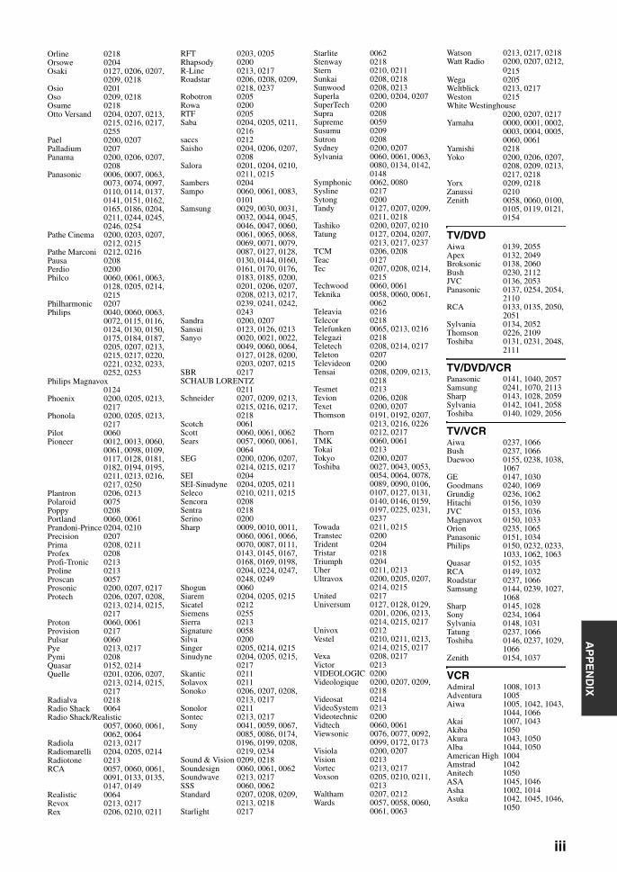
AP
PE
ND
IX
Orline 0218Orsowe 0204Osaki 0127, 0206, 0207,
0209, 0218Osio 0201Oso 0209, 0218Osume 0218Otto Versand 0204, 0207, 0213,
0215, 0216, 0217, 0255
Pael 0200, 0207Palladium 0207Panama 0200, 0206, 0207,
0208Panasonic 0006, 0007, 0063,
0073, 0074, 0097, 0110, 0114, 0137, 0141, 0151, 0162, 0165, 0186, 0204, 0211, 0244, 0245, 0246, 0254
Pathe Cinema 0200, 0203, 0207, 0212, 0215
Pathe Marconi 0212, 0216Pausa 0208Perdio 0200Philco 0060, 0061, 0063,
0128, 0205, 0214, 0215
Philharmonic 0207Philips 0040, 0060, 0063,
0072, 0115, 0116, 0124, 0130, 0150, 0175, 0184, 0187, 0205, 0207, 0213, 0215, 0217, 0220, 0221, 0232, 0233, 0252, 0253
Philips Magnavox0124
Phoenix 0200, 0205, 0213, 0217
Phonola 0200, 0205, 0213, 0217
Pilot 0060Pioneer 0012, 0013, 0060,
0061, 0098, 0109, 0117, 0128, 0181, 0182, 0194, 0195, 0211, 0213, 0216, 0217, 0250
Plantron 0206, 0213Polaroid 0075Poppy 0208Portland 0060, 0061Prandoni-Prince 0204, 0210Precision 0207Prima 0208, 0211Profex 0208Profi-Tronic 0213Proline 0213Proscan 0057Prosonic 0200, 0207, 0217Protech 0206, 0207, 0208,
0213, 0214, 0215, 0217
Proton 0060, 0061Provision 0217Pulsar 0060Pye 0213, 0217Pymi 0208Quasar 0152, 0214Quelle 0201, 0206, 0207,
0213, 0214, 0215, 0217
Radialva 0218Radio Shack 0064Radio Shack/Realistic
0057, 0060, 0061, 0062, 0064
Radiola 0213, 0217Radiomarelli 0204, 0205, 0214Radiotone 0213RCA 0057, 0060, 0061,
0091, 0133, 0135, 0147, 0149
Realistic 0064Revox 0213, 0217Rex 0206, 0210, 0211
RFT 0203, 0205Rhapsody 0200R-Line 0213, 0217Roadstar 0206, 0208, 0209,
0218, 0237Robotron 0205Rowa 0200RTF 0205Saba 0204, 0205, 0211,
0216saccs 0212Saisho 0204, 0206, 0207,
0208Salora 0201, 0204, 0210,
0211, 0215Sambers 0204Sampo 0060, 0061, 0083,
0101Samsung 0029, 0030, 0031,
0032, 0044, 0045, 0046, 0047, 0060, 0061, 0065, 0068, 0069, 0071, 0079, 0087, 0127, 0128, 0130, 0144, 0160, 0161, 0170, 0176, 0183, 0185, 0200, 0201, 0206, 0207, 0208, 0213, 0217, 0239, 0241, 0242, 0243
Sandra 0200, 0207Sansui 0123, 0126, 0213Sanyo 0020, 0021, 0022,
0049, 0060, 0064, 0127, 0128, 0200, 0203, 0207, 0215
SBR 0217SCHAUB LORENTZ
0211Schneider 0207, 0209, 0213,
0215, 0216, 0217, 0218
Scotch 0061Scott 0060, 0061, 0062Sears 0057, 0060, 0061,
0064SEG 0200, 0206, 0207,
0214, 0215, 0217SEI 0204SEI-Sinudyne 0204, 0205, 0211Seleco 0210, 0211, 0215Sencora 0208Sentra 0218Serino 0200Sharp 0009, 0010, 0011,
0060, 0061, 0066, 0070, 0087, 0111, 0143, 0145, 0167, 0168, 0169, 0198, 0204, 0224, 0247, 0248, 0249
Shogun 0060Siarem 0204, 0205, 0215Sicatel 0212Siemens 0255Sierra 0213Signature 0058Silva 0200Singer 0205, 0214, 0215Sinudyne 0204, 0205, 0215,
0217Skantic 0211Solavox 0211Sonoko 0206, 0207, 0208,
0213, 0217Sonolor 0211Sontec 0213, 0217Sony 0041, 0059, 0067,
0085, 0086, 0174, 0196, 0199, 0208, 0219, 0234
Sound & Vision 0209, 0218Soundesign 0060, 0061, 0062Soundwave 0213, 0217SSS 0060, 0062Standard 0207, 0208, 0209,
0213, 0218Starlight 0217
Starlite 0062Stenway 0218Stern 0210, 0211Sunkai 0208, 0218Sunwood 0208, 0213Superla 0200, 0204, 0207SuperTech 0200Supra 0208Supreme 0059Susumu 0209Sutron 0208Sydney 0200, 0207Sylvania 0060, 0061, 0063,
0080, 0134, 0142, 0148
Symphonic 0062, 0080Sysline 0217Sytong 0200Tandy 0127, 0207, 0209,
0211, 0218Tashiko 0200, 0207, 0210Tatung 0127, 0204, 0207,
0213, 0217, 0237TCM 0206, 0208Teac 0127Tec 0207, 0208, 0214,
0215Techwood 0060, 0061Teknika 0058, 0060, 0061,
0062Teleavia 0216Telecor 0218Telefunken 0065, 0213, 0216Telegazi 0218Teletech 0208, 0214, 0217Teleton 0207Televideon 0200Tensai 0208, 0209, 0213,
0218Tesmet 0213Tevion 0206, 0208Texet 0200, 0207Thomson 0191, 0192, 0207,
0213, 0216, 0226Thorn 0212, 0217TMK 0060, 0061Tokai 0213Tokyo 0200, 0207Toshiba 0027, 0043, 0053,
0054, 0064, 0078, 0089, 0090, 0106, 0107, 0127, 0131, 0140, 0146, 0159, 0197, 0225, 0231, 0237
Towada 0211, 0215Transtec 0200Trident 0204Tristar 0218Triumph 0204Uher 0211, 0213Ultravox 0200, 0205, 0207,
0214, 0215United 0217Universum 0127, 0128, 0129,
0201, 0206, 0213, 0214, 0215, 0217
Univox 0212Vestel 0210, 0211, 0213,
0214, 0215, 0217Vexa 0208, 0217Victor 0213VIDEOLOGIC 0200Videologique 0200, 0207, 0209,
0218Videosat 0214VideoSystem 0213Videotechnic 0200Vidtech 0060, 0061Viewsonic 0076, 0077, 0092,
0099, 0172, 0173Visiola 0200, 0207Vision 0213Vortec 0213, 0217Voxson 0205, 0210, 0211,
0213Waltham 0207, 0212Wards 0057, 0058, 0060,
0061, 0063
Watson 0213, 0217, 0218Watt Radio 0200, 0207, 0212,
0215Wega 0205Weltblick 0213, 0217Weston 0215White Westinghouse
0200, 0207, 0217Yamaha 0000, 0001, 0002,
0003, 0004, 0005, 0060, 0061
Yamishi 0218Yoko 0200, 0206, 0207,
0208, 0209, 0213, 0217, 0218
Yorx 0209, 0218Zanussi 0210Zenith 0058, 0060, 0100,
0105, 0119, 0121, 0154
TV/DVDAiwa 0139, 2055Apex 0132, 2049Broksonic 0138, 2060Bush 0230, 2112JVC 0136, 2053Panasonic 0137, 0254, 2054,
2110RCA 0133, 0135, 2050,
2051Sylvania 0134, 2052Thomson 0226, 2109Toshiba 0131, 0231, 2048,
2111
TV/DVD/VCRPanasonic 0141, 1040, 2057Samsung 0241, 1070, 2113Sharp 0143, 1028, 2059Sylvania 0142, 1041, 2058Toshiba 0140, 1029, 2056
TV/VCRAiwa 0237, 1066Bush 0237, 1066Daewoo 0155, 0238, 1038,
1067GE 0147, 1030Goodmans 0240, 1069Grundig 0236, 1062Hitachi 0156, 1039JVC 0153, 1036Magnavox 0150, 1033Orion 0235, 1065Panasonic 0151, 1034Philips 0150, 0232, 0233,
1033, 1062, 1063Quasar 0152, 1035RCA 0149, 1032Roadstar 0237, 1066Samsung 0144, 0239, 1027,
1068Sharp 0145, 1028Sony 0234, 1064Sylvania 0148, 1031Tatung 0237, 1066Toshiba 0146, 0237, 1029,
1066Zenith 0154, 1037
VCRAdmiral 1008, 1013Adventura 1005Aiwa 1005, 1042, 1043,
1044, 1066Akai 1007, 1043Akiba 1050Akura 1043, 1050Alba 1044, 1050American High 1004Amstrad 1042Anitech 1050ASA 1045, 1046Asha 1002, 1014Asuka 1042, 1045, 1046,
1050
iii

© 2009 Yamaha Corporation All rights reserved. Printed in China WQ96020
Audio Dynamics1000Audiovox 1003Baird 1042, 1043, 1047Basic Line 1044, 1050Baur 1046Beaumark 1002, 1014Bell & Howell 1001Blaupunkt 1046, 1048Broksonic 1012, 1013Bush 1044, 1050, 1066Calix 1003Candle 1002, 1003Canon 1004CCE 1006CGE 1042, 1043Cimline 1044, 1050Citizen 1002, 1003Colortyme 1000Colt 1006Craig 1002, 1003, 1006,
1014Crown 1050Curtis Mathes 1000, 1002, 1004,
1009Cybernex 1002, 1014Daewoo 1005, 1038, 1061,
1067Dansai 1050Dantax 1044DBX 1000De Graaf 1046, 1049Decca 1042, 1043, 1046Denon 1010Dimensia 1009Dual 1043, 1046Dumont 1042, 1046, 1047,
1049Dynatech 1005Electrohome 1003Electrophonic 1003Elta 1050Emerson 1003, 1004, 1005,
1012, 1013Etzuko 1050Ferguson 1043Fidelity 1042Finlandia 1046, 1047, 1049Finlux 1042, 1043, 1046,
1047, 1049FIRST LINE 1044, 1045, 1049,
1050Fisher 1001, 1047Flint 1044Formenti/Phoenix
1046Fuji 1004Fujitsu 1042Funai 1005, 1042Galaxy 1042Garrard 1005GBC 1050GE 1002, 1004, 1009,
1014, 1030GEC 1046Geloso 1050General Technic 1044, 1048Go Video 1014GoldHand 1050Goldstar 1000, 1003, 1042,
1045Goodmans 1042, 1045, 1050,
1069Gradiente 1005Graetz 1043, 1047Granada 1046, 1047, 1049Grandin 1042, 1045, 1050Grundig 1046, 1050, 1062Hanseatic 1045, 1046Harley Davidson1005Harman/Kardon 1000
Harwood 1006HCM 1050Headquarter 1001Hinari 1044, 1050Hisawa 1044Hitachi 1007, 1010, 1039,
1042, 1043, 1046, 1049
Hughes Network Systems1010
Hypson 1044, 1050Imperial 1042Inno Hit 1046, 1050Innovation 1044, 1048Instant Replay 1004Interbuy 1045Interfunk 1046, 1047Intervision 1042Irradio 1045, 1050ITT 1043, 1047ITV 1045JC Penney 1000, 1001, 1002,
1003, 1004, 1006JCL 1004Jensen 1007JVC 1000, 1001, 1007,
1011, 1017, 1036, 1043
Kaisui 1050Karcher 1046Kendo 1044Kenwood 1000, 1001, 1007,
1011, 1043KLH 1006Kodak 1003, 1004Korpel 1050Leyco 1050LG 1003, 1042, 1045,
1071Lifetec 1044, 1048Lloyd’s 1005Loewe 1048Loewe Opta 1045, 1046Logik 1006, 1050Luxor 1047LXI 1003M Electronic 1042Magnasonic 1047Magnavox 1004, 1018, 1033Magnin 1003, 1014Manesth 1050Marantz 1000, 1001, 1004,
1046, 1051Marta 1003Matsui 1044, 1045Matsushita 1004Mediator 1046Medion 1044, 1048MEI 1004
Memorex 1001, 1002, 1003, 1004, 1005, 1008, 1013, 1014, 1042, 1045, 1047
Memphis 1050Metz 1048MGA 1014MGN Technology
1002, 1014Micromaxx 1044, 1048Microstar 1044, 1048Migros 1042Minolta 1010Mitsubishi 1011, 1042, 1046Montgomery Ward
1008Motorola 1004, 1008MTC 1002, 1014Multitech 1002, 1005, 1006,
1042, 1046, 1050Murphy 1042
National 1048NEC 1000, 1001, 1007,
1011, 1043, 1051Neckermann 1043, 1046NEI 1046Nesco 1050Nikko 1003Noblex 1002, 1014Nokia 1043, 1047Nordmende 1043Oceanic 1042, 1043Okano 1044Olympus 1004Optimus 1003, 1008Orion 1012, 1013, 1044,
1065Orson 1042Osaki 1042, 1045, 1050Otto Versand 1046Palladium 1043, 1045, 1050Panasonic 1004, 1020, 1034,
1040, 1048, 1054, 1072
Pathe Marconi 1043Penney 1010, 1014Pentax 1010, 1049Perdio 1042Philco 1004, 1051Philips 1004, 1025, 1033,
1046, 1056, 1057, 1059, 1062, 1063
Philips Magnavox1018
Phonola 1046Pilot 1003Pioneer 1011, 1046Prinz 1042Profex 1050Profitronic 1014Proline 1042Proscan 1009Prosonic 1044Protec 1006Pye 1046, 1056Quarter 1001Quartz 1001, 1047Quasar 1004, 1035Quelle 1042, 1046, 1047Radio Shack 1003Radio Shack/Realistic
1001, 1002, 1003, 1004, 1005, 1008
Radiola 1046Radix 1003Randex 1003RCA 1002, 1004, 1009,
1010, 1014, 1015, 1022, 1032
Realistic 1001, 1002, 1003, 1004, 1005, 1008
Rex 1043RFT 1046Roadstar 1045, 1050, 1066Saba 1043Saisho 1044, 1050Salora 1047Samsung 1002, 1014, 1021,
1027, 1052, 1068, 1070
Sanky 1008Sansui 1007, 1011, 1013,
1043Sanyo 1001, 1002, 1014,
1047SBR 1046Schaub Lorenz 1042, 1043, 1047Schneider 1042, 1044, 1045,
1046, 1050Scott 1012
Sears 1001, 1003, 1004, 1010
SEG 1050SEI-Sinudyne 1046Seleco 1043Sentron 1050Sharp 1008, 1023, 1028,
1053, 1073Shintom 1006, 1047, 1050Shivaki 1045Shogun 1002, 1014Siemens 1045, 1047Signature 2000 1008Silva 1045Singer 1004, 1006Sinudyne 1046Sontec 1045Sony 1016, 1019, 1055,
1060, 1064, 1074STS 1004, 1010Sunkai 1044Sunstar 1042Suntronic 1042Sunwood 1050Sylvania 1004, 1005, 1031,
1041Symphonic 1005Taisho 1044Tandy 1001Tashiko 1003, 1042Tatung 1007, 1042, 1043,
1046, 1066TCM 1044, 1048Teac 1005, 1007Technics 1004, 1048Teknika 1003, 1004, 1005Teleavia 1043Telefunken 1043Tenosal 1050Tensai 1042, 1045, 1050Tevion 1044, 1048Thomson 1043, 1058Thorn 1043, 1047TMK 1002, 1014Tokai 1045, 1050Tonsai 1050Toshiba 1013, 1024, 1029,
1043, 1046, 1066, 1075
Totevision 1002, 1003, 1014Towada 1050Towika 1050Uher 1045Unitech 1002, 1014Universum 1042, 1045, 1046Vector Research 1000Video Concepts 1000Videon 1044, 1048Videosonic 1002, 1014Wards 1002, 1003, 1004,
1005, 1006, 1008, 1010, 1014
Weltblick 1045White Westinghouse
1013XR-1000 1004, 1005, 1006Yamaha 1000, 1001, 1007Yamishi 1050Yokan 1050Yoko 1045, 1050Zenith 1013, 1026, 1037


