Rainer Wesche, HTS 4 Fusion Conductor Workshop, Karlsruhe, May 26-27, 2011 1 HTS Conductors for Fusion Thermal Stability and Quench R. Wesche, P. Bruzzone, S. March, C. Marinucci, D. Uglietti
Transcript
Rainer Wesche, HTS4Fusion Conductor Workshop, Karlsruhe, May 26-27, 2011 1
HTS Conductors for Fusion
Thermal Stability and Quench
R. Wesche, P. Bruzzone, S. March, C. Marinucci, D. Uglietti
Rainer Wesche, HTS4Fusion Conductor Workshop, Karlsruhe, May 26-27, 2011 2
Outline
• Overview on HTS activities performed since 1992 at CRPP• Running HTS Current Lead Projects
• EDIPO 18 kA HTS current leads• HZB 20 kA HTS current leads
• Development of industrial HTS current leads in collaboration with WEKA
• HTS Insert Coil Project• HTS insert coil for a 12 T Nb3Sn laboratory magnet
• HTS for Fusion• Properties of second generation HTS• Temperature margins
• Simple stability considerations
• Quench Behavior of Large RE-123 Conductors• Feasibility of He gas cooling at Top 50 K
• Results of quench calculations using the CryoSoftTM code THEA
Rainer Wesche, HTS4Fusion Conductor Workshop, Karlsruhe, May 26-27, 2011 3
• Bi-2212 powder was prepared by solid state reaction of Bi2O3, SrCO3, CaO, and CuO
• Starting powders with a small amount of minor phases lead to strongly enhanced JcR. Wesche, B. Jakob, G. Pasztor, IEEE Trans. Appl. Supercond. 3 (1993) 927
• Jc of Ag/Bi-2212 wires was found to increase with decreasing wire diameter suggesting a better connectivity of the grains at the Ag/Bi-2212 interfaceR. Wesche, A.M. Fuchs, B. Jakob, G. Pasztor, Cryogenics 34 (1994) 805
• Jc vs axial tensile strainMono-core wiresAg: irr 0.1%AgNiMg: irr 0.5%Larger residual compressive strain in HTS core of AgNiMg/Bi-2212 wiresR. Wesche, A.M. Fuchs, B. Jakob, G. Pasztor, Cryogenics 36 (1996) 419
jc
n
Ag AgNiMg
Ag AgNiMg
Rainer Wesche, HTS4Fusion Conductor Workshop, Karlsruhe, May 26-27, 2011 4
HTS Projects of CRPP (1992 – 2005) –Development of HTS Current Leads
Design, manufacture and testing of a binary 2 kA HTS current lead using Bi-2212 bulk material (NFP 30 (1992-1995)/supported by Swiss National Science Foundation)R. Wesche & A.M. Fuchs, Cryogenics 34 (1994) 145, A.M. Fuchs et al., Cryogenics 34 ICEC Supplement (1994) 627
European Fusion Development Agreement (EFDA):
In a collaboration of CRPP and KIT (former FZK) a 70 kA HTS current lead demonstrator has been developed.
Phase I: Development of 10 kA HTS current leads (Test at CRPP)R. Heller, M. Tasca, P. Erismann, A.M. Fuchs, M. Vogel, IEEE Trans. Appl. Supercond. 10 (2000) 1470
R. Heller, G. Friesinger, A.M. Fuchs, R. Wesche, IEEE Trans. Appl. Supercond. 12 (2002) 1285
A.M. Fuchs, R. Wesche, A. Anghel, F. Roth, R. Heller, M. Tasca, IEEE Trans. Appl. Supercond. 12 (2002) 1281
Phase II: Development of 20 kA HTS current leads (Test at NIFS (Japan))R. Heller, G. Friesinger, A.M. Fuchs, T. Mito, S. Satoh, K. Takahata, M. Tasca, M. Vogel, Cryogenics 41 (2001) 539
Phase III: Design, manufacture and test of a 70 kA CL demonstrator (Test in TOSCA facility of KIT (former FZK)R. Heller, W.H. Fietz, F. Hurd, A. Vostner, R. Wesche, G. Zahn et al., IEEE Trans. Appl. Supercond. 15 (2005) 1496
Rainer Wesche, HTS4Fusion Conductor Workshop, Karlsruhe, May 26-27, 2011 5
HTS Projects of CRPP (1992 – 2005) –Development of HTS Current Leads
10 kA HTS CL using Ag/Au clad Bi-2212 bulk materialA.M. Fuchs, R. Wesche, A. Anghel, F. Roth, R. Heller, M. Tasca, IEEE Trans. Appl. Supercond. 12 (2002) 1281
Bi-2212 bulk tube (d 50 mm) + 0.2 mm Ag/Au layer Ic 5 kA at 65 K (NEXANS)
Wire bundle heat exchanger
Bi-2212 bulk tube
70 kA HTS CL demonstrator using AgAu/Bi-2223 tapes (AMSC)R. Heller, W.H. Fietz, F. Hurd, A. Vostner, R. Wesche, G. Zahn et al., IEEE Trans. Appl. Supercond. 15 (2005) 1496
Rainer Wesche, HTS4Fusion Conductor Workshop, Karlsruhe, May 26-27, 2011 6
HTS Projects of CRPP (1992 – 2005) –Cable Demonstrator (Test without HV)
Ipeak = 2.5 kA
Top = 60 K
AC loss at 60 K0.31 0.02 W/m
Thermal losses0.6 W/m
Ne gas coolingTin: 50 – 70 K
A. Anghel et al., Adv. Cryogenic Eng., vol. 45, eds. Shu et al., Kluwer Academic/Plenum Publishers, 2000, pp 1419G. Pasztor et al., Inst. Phys. Conf. Ser. No. 167, IOP Publishing, 2000, pp 1119R. Wesche et al., Cryogenics 39 (1999) 767
Ne refrigeratorPrototype cable
DAS
Cu bus bar
Cable termination
Former diameter: 53 mmCorrugated steel pipes: 60.4/66.0 mmCorrugated steel pipes: 98.0/109.2 mmOuter diameter: 158 mm
Rainer Wesche, HTS4Fusion Conductor Workshop, Karlsruhe, May 26-27, 2011 7
HTS Projects of CRPP (1992 – 2005) –Cable Prototype (Test without HV)
HTS prototype cable of 5 m length2 40 AgMg/Bi-2223 tapes (VAC) Ic(77 K, B = 0) = 30 A
Measured AC loss at 50 HzPAC of the two-layer cable close to the expectations for a monoblock model
Iouter : Iinner = 52 : 48
Irms
Ic: 4.9 kA (50 K), 1.57 kA (77 K) PAC decreases with decreasing Top
Rainer Wesche, HTS4Fusion Conductor Workshop, Karlsruhe, May 26-27, 2011 8
Running HTS Current Lead Projects –18 kA EDIPO HTS Current Leads
Main design values
Heat exchanger (copper part)No. of Cu wires (d = 0.1 mm) 100675Cu cross-section (cm2) 7.91Steel tube Di /Do (mm) 84.9 / 88.9Free length of Cu wires (mm) 490Effective length of corrugated Cu wires (mm) 688Helium inlet temperature (K) 75Helium mass flow rate at 17 kA (g/s) 1.86
HTS module (HTS: AgMgAu/Bi-2223 tapes (Bruker HTS))Number of eight-fold stacks 65Length of HTS stacks (mm) 470Outer diameter (mm) 105.2Warm end HTS temperature at 17 kA (K) 80Conduction heat load at 4.5 K (W) 5.1
Warm end Cu connection
Heat exchanger
HTS module
Cold end Cu connection
Rainer Wesche, HTS4Fusion Conductor Workshop, Karlsruhe, May 26-27, 2011 9
Running HTS Current Lead Projects –18 kA EDIPO HTS Current Leads
Results for steady state operation Tcs for test without EDIPO main magnet
• Mass flow rates required to reach a He outlet temperature between 261 and 276 K.• At nominal current (17 kA) dT/dx 0 at warm end.• Increasing THTS
w – THein at reduced
currents allows us to reach again dT/dx 0
• By means of a heater the THein is slowly
increased until a quench occurs.• Current lead test: B 10 mT at 18 kA• Later operation: B 30 mT at 18 kA• Sufficient margin for current leads operation at 18 kA
Minimum safety margin
Rainer Wesche, HTS4Fusion Conductor Workshop, Karlsruhe, May 26-27, 2011 10
Running HTS Current Lead Projects –20 kA HTS Current Leads for HZB Hybrid Magnet System
Main design values
Heat exchanger (copper part)No. of Cu wires (d = 0.1 mm) 118436Cu cross-section (cm2) 9.302Steel tube Di /Do (mm) 84.9 / 88.9Free length of Cu wires (mm) 440Effective length of corrugated Cu wires (mm) 618Helium inlet temperature (K) 44.0Helium mass flow rate at 20 kA (g/s) 1.37
HTS module (HTS: AgMgAu/Bi-2223 tapes (Bruker HTS))Number of eight-fold stacks 28Length of HTS stacks (mm) 470Outer diameter (mm) 59.8Magnetic stray field (mT) 152Warm end HTS temperature at 20 kA (K) 53.7Conduction heat load at 4.5 K (W) 1.37
Rainer Wesche, HTS4Fusion Conductor Workshop, Karlsruhe, May 26-27, 2011 11
Running HTS Current Lead Projects –20 kA HTS Current Leads for HZB Hybrid Magnet System
Calculated T profile after a loss of flow (I = 20 kA = constant, n = 15)
125.5 s after a loss of flow a hot spot starts to evolve.Voltage across the HTS module: 10 mVTHTS
w 79 KTHTS
p 83 K
Calculated temperatures during a safety discharge (I = I0 exp(-t/), Udet = 10 mV)
Udet (mV) THTSp (K)
10 88.723.5 100.435.1 111.647.4 123.0
Rainer Wesche, HTS4Fusion Conductor Workshop, Karlsruhe, May 26-27, 2011 12
Running HTS Current Lead Projects –Development of Industrial HTS CL’s (CRPP-WEKA)
In a collaboration of CRPP and WEKA AG HTS current leads for the current range of 3 to 30 kA suitable for an industrial fabrication process are presently under development.
Target of the 2-year project: Design, manufacture and test of a pair of10 kA HTS current leads.
The project is financially supported by the KTI (Bundesamt für Berufsbildung und Technologie BBT, Förderagentur für Innovation KTI).
Rainer Wesche, HTS4Fusion Conductor Workshop, Karlsruhe, May 26-27, 2011 13
HTS Insert Coil Project – Motivation
Limits of Nb3Sn at Top = 4.2 KBc2(4.2 K) < 26 T, max = 200 MPaMagnet cost and size increase considerably with increasing fieldFor generation of B > 25 T very expensive hybrid/resistive magnets are neededRE-123 on Hastelloy substrate provides large Jc even at B > 20 T and can withstand a tensile stress over 500 MPa.
Tohoku University (Japan)
Operation up to a stress of 1000 MPa
G. Nishima et al., IEEE Trans. Appl. Supercond. 18 (2008) 1131
ISTEC (2007 Japan)
600 turns, 128 m YBCO tape
140 turns, 14 m GdBCO tape
Tape produced in house6 T in Bb = 14 T at 700 A (424 MPa)
1 T in Bb = 28 T at 512 A (210 MPa)
H. Fukushima et al., Proceeding of the Autumn Meeting of the Cryogenic Society of Japan (2007) p. 204
Rainer Wesche, HTS4Fusion Conductor Workshop, Karlsruhe, May 26-27, 2011 14
HTS Insert Coil Project – Motivation
NHFML (USA)
in = 79 mmout = 81 mmH = 25 mm
Operation up to 760 MPa
Protected and unprotected quenches
50 turns, 25 m long tapeGlass/paper insulation 2.8 T in Bb = 31 T at
325 A (466 MPa)
in = 25 mmout = 36.5 mmH= 47 mm38 turns, 36 m long tapeVarnish insulation
W.D. Markiewicz et al., AIP Conference Proceedings 1218 (2010) 225-230
Rainer Wesche, HTS4Fusion Conductor Workshop, Karlsruhe, May 26-27, 2011 15
HTS Insert Coil Project –Development of a coated conductor insert coil at CRPP
GOAL: insert coil for a 12 (15 T) LTS laboratory magnet (bore 80 mm)
Coil specifications
• Dimensions: bore 40 mm, outer diameter 70 mm, height 120 mm
• Standard 4 mm Superpower tape (300 m long) with electroplated copper (0.40 mm2)
• Target field: 4 T at 250 A(280 A/mm2 in the winding)
• Inductance about 50 mH, stored energy about 2000 J
Rainer Wesche, HTS4Fusion Conductor Workshop, Karlsruhe, May 26-27, 2011 16
Field uniformity: 1% homogeneity in a 30 mm sphere is maintained after upgrade.
Mechanical analysis
• Hoop force is less than 110 N; the corresponding tensile strain on the outer radius was estimated to be 0.17% (E = 160 GPa). The tape can withstand more than 200 N.
• The radial tensile stress could reach 5 MPa (layers detaching from each others). It can be compensated by a moderate winding tension or by sub-dividing in two thinner coils.
HTS Insert Coil Project –Development of a coated conductor insert coil at CRPP
Insulation• Enamel applied in house: less than 50 μm per side.• Standard polyimide tape insulation is too thick: > 100 μm per side.
Bare tape 4 x 0.15 = 0.6 mm2
Kapton ins. tape 4.1 x 0.35 = 1.4 mm2
Enamel ins. tape 4 x 0.25 = 0.1 mm2
Rainer Wesche, HTS4Fusion Conductor Workshop, Karlsruhe, May 26-27, 2011 17
HTS Insert Coil Project – Protection
Protection• Passive circuit with resistor and diodes.• Even if the standard copper cross section from Superpower (0.2 mm2) is
enough, the cross section of 0.4 mm2 was chosen for extra margin.• Such cross section, in conjunction with sensitive quench detection system
(less than 100 mV) and fast dumping circuit (tau shorter than 100 ms) ensures that the temperature during quench is limited to < 200 K.
• In case the detection level is higher or the dumping time is longer (larger coils), larger copper cross section is mandatory in order to maintain the temperature below 200 K.
The project is financially supported by the Swiss National Science Foundation
Rainer Wesche, HTS4Fusion Conductor Workshop, Karlsruhe, May 26-27, 2011 18
HTS for Fusion – Results of Early Studies
The possibilities to use HTS for fusion have been already studied in the EFDA tasks HTSPER and HTSMAG
In general, the use HTS would offer the possibility to operate at elevated temperatures and/or higher fields. HTS would provide larger temperature margins and improved stability (especially at elevated operation temperatures)
Studied scenarios
Bi-2212 high field option Top 4.5 K (However, the maximum possible B limited by the forces in the structure. Moreover, larger neutron wall load is undesirable.)
Bi-2223 intermediate temperature (20 – 30 K) & field option (12 – 14 T) providing reduced cooling cost for the magnets. However, the cost savings are small considering the whole cryogenic system (cryopumps, cooling of cryogenic shields, circulating pumps).
RE-123 at elevated temperatures ( 50 K) and fields of up to 14 T. Highest potential to simplify the cryogenic system (no thermal shields may be required).
Rainer Wesche, HTS4Fusion Conductor Workshop, Karlsruhe, May 26-27, 2011 19
HTS for Fusion –Properties of second generation HTS
Commercially available RE-123 coated conductors of SuperPower
Rainer Wesche, HTS4Fusion Conductor Workshop, Karlsruhe, May 26-27, 2011 20
HTS for Fusion –Properties of second generation HTS
q
irr
p
irrirrc TB
BTB
BTBBATBj
1,
Critical current density in the RE-123 layer
cirrirr T
TBTB 10
Parameter ValueTc [K] 92Birr(0) [T](B broad face)
132.5
A [Nm-3T-] 4.52108
p 0.653q 2.568 1.5 1.789
Rainer Wesche, HTS4Fusion Conductor Workshop, Karlsruhe, May 26-27, 2011 21
HTS for Fusion –Properties of second generation HTS
Copper: 8900 kg/m3
Hastelloy: 8890 kg/m3
YBCO: 6380 kg/m3
Thermal conductivities Specific heats
Densities
Rainer Wesche, HTS4Fusion Conductor Workshop, Karlsruhe, May 26-27, 2011 22
HTS for Fusion – Temperature Margins
Comparison of the temperature margins of RE-123 and Nb3Sn (-0.6% axial compressive strain). For RE-123 the unfavorable field direction (B) has been considered. The relevant B is typically considerably lower than the maximum field relevant for Nb3Sn.
Top ≤ 50 KT(RE-123) >> T(Nb3Sn)
Rainer Wesche, HTS4Fusion Conductor Workshop, Karlsruhe, May 26-27, 2011 23
Rainer Wesche, HTS4Fusion Conductor Workshop, Karlsruhe, May 26-27, 2011 25
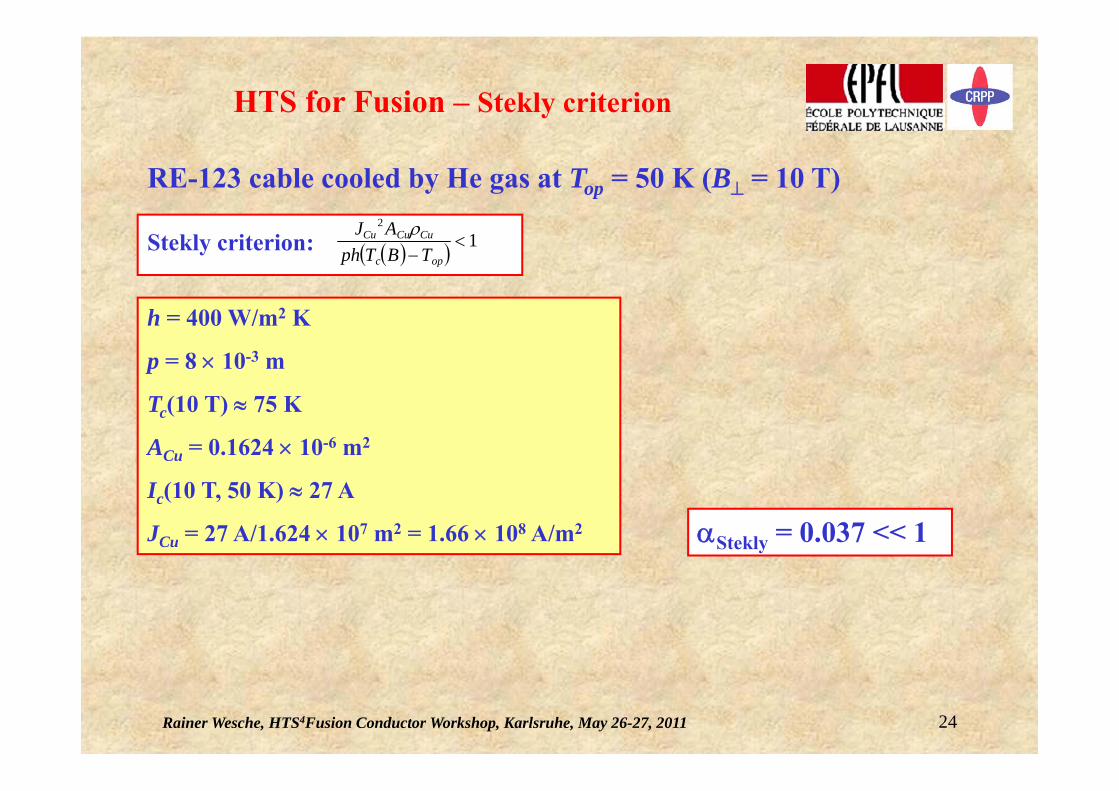
Quench Behavior of Large RE-123 Conductors –Feasibility of He gas cooling at Top 50 K
Cable of 300 m length, external heat input: 1 W/m
Tin = 50 K
Tout = 67.5 K
pin = 10 bar
pout = 7 bar
Steady state
dm/dt = 3.7 g/s
Rainer Wesche, HTS4Fusion Conductor Workshop, Karlsruhe, May 26-27, 2011 26
Quench Behavior of Large RE-123 Conductors –Quench Calculations using THEA
Presentation based on the results presented in paper 4LPM-6 at ASC 2010C. Marinucci, L. Bottura, M. Calvi, R. Wesche, Quench analysis of a high-current forced-flow HTS conductor model
Motivation:
A fundamental understanding of the quench phenomenon is particularly important in the design and operation of magnets using HTS because of the low quench propagation velocity.
To study the quench behavior of a high-current forced-flow conductor model the CryoSoftTM code THEA has been used.
Goal:
Assessment of the key quench parameters (temperature increase, quench propagation velocity, He pressure, mass flow rate) of a high-current forced-flow cooled RE-123 full size conductor model in a broad range of model and physical parameters.
Rainer Wesche, HTS4Fusion Conductor Workshop, Karlsruhe, May 26-27, 2011 27
Quench Behavior of Large RE-123 Conductors –HTS Conductor Model
Stack of 1233 (RE)BCO tapes at
Bop = 10 T (perpendicular field)Top = 50 KIop = 16.5 kA
Current sharing temperature Tcs = 58 K.
Cooling by forced flow of gaseous helium.
Bare bone design, not necessarily a realistic conductor.
SuperPower 2G (RE)BCO-HTS Tape SCS4050 as the reference tape to test the method.
Operating conditionsBased on general cryogenic considerations (considerably lower cryogenic costs at T > 50 K when using coated conductors for fusion devices) and tape critical current density rather than on a detailed thermodynamic analysis.
Rainer Wesche, HTS4Fusion Conductor Workshop, Karlsruhe, May 26-27, 2011 28
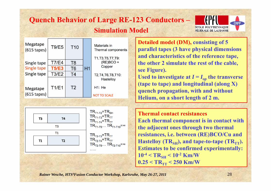
Quench Behavior of Large RE-123 Conductors –Simulation Model
Detailed model (DM), consisting of 5 parallel tapes (3 have physical dimensions and characteristics of the reference tape, the other 2 simulate the rest of the cable, see Figure).Used to investigate at I = Iop the transverse (tape to tape) and longitudinal (along X) quench propagation, with and without Helium, on a short length of 2 m.
Thermal contact resistancesEach thermal component is in contact with the adjacent ones through two thermal resistances, i.e. between (RE)BCO/Cu and Hastelloy (TRSH), and tape-to-tape (TRTT).Estimates to be confirmed experimentally:10-4 < TRSH < 10-2 Km/W0.25 < TRTT < 250 Km/W
Rainer Wesche, HTS4Fusion Conductor Workshop, Karlsruhe, May 26-27, 2011 29
p = constant at He inlet and outlet.pin = 10 barp = 1 bar on 100 m.
Steady state: dm/dt = 3.7 g/s Residence time (300 m) = 2 min.
Quench Behavior of Large RE-123 Conductors –Cryogenic System & Perturbation Scenarios
Constant external heat perturbationDeposited in T5 Q = 1000 W/m (scenario H) and Q = 100 W/m (other scenarios)
Cryogenic System
Rainer Wesche, HTS4Fusion Conductor Workshop, Karlsruhe, May 26-27, 2011 30
Quench Behavior of Large RE-123 Conductors –Model and Simulation Data
Reference case TRSH = 2 10-3 Km/W, TRTT = 8 Km/W
Rainer Wesche, HTS4Fusion Conductor Workshop, Karlsruhe, May 26-27, 2011 31
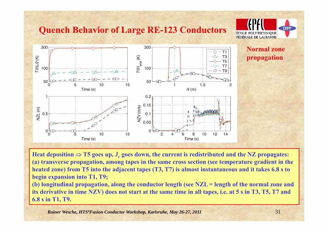
Quench Behavior of Large RE-123 Conductors
Heat deposition T5 goes up, Jc goes down, the current is redistributed and the NZ propagates:(a) transverse propagation, among tapes in the same cross section (see temperature gradient in the heated zone) from T5 into the adjacent tapes (T3, T7) is almost instantaneous and it takes 6.8 s to begin expansion into T1, T9; (b) longitudinal propagation, along the conductor length (see NZL = length of the normal zone and its derivative in time NZV) does not start at the same time in all tapes, i.e. at 5 s in T3, T5, T7 and 6.8 s in T1, T9.
Normal zone propagation
Rainer Wesche, HTS4Fusion Conductor Workshop, Karlsruhe, May 26-27, 2011 32
Quench Behavior of Large RE-123 Conductors
Quench temperatureThe peak quench temperature Tmax = 300 K in T5, above the limit to avoid critical thermal stresses (~ 200 K).The temperature in the Hastelloy is practically the same as in RE-123/Cu because of the good thermal contact.
Effect of the helium flow
Beneficial for longitudinal quench propagation, i.e. moving the normal zone downstream and thus reducing Tmax in the heated zone. With no cooling the normal zone is practically confined to its initial position (NZL = LP and NZV = 0). In our model helium is in contact with all tapes. The cooling system could be optimized to enhance the quench forward process and facilitate the detection of the NZ.
No He
He flow
Rainer Wesche, HTS4Fusion Conductor Workshop, Karlsruhe, May 26-27, 2011 33
Quench Behavior of Large RE-123 Conductors
Sensitivity studyEffect of the thermal resistance tape-to-tape TRTTRelevant on the transverse quench propagation:Tmax = 320 K - 120 K as TRTT = 250 - 0.25 Km/WNZL and NZV are unaffected.
Homogenous model (HM), consisting of one mega-tape with all 1233 tapes in perfect thermal and electrical contact. Used to investigate the quench, with detection and current dump, along the full conductor length of 300 m.
The sensitivity of the quench propagation results to variation of the thermal resistance between RE-123/Cu and Hastelloy is < 5%.The sensitivity is completely negligible to variation of theelectrical conductance in the range 106 (Reference case) to 103 -1 m-1.
Rainer Wesche, HTS4Fusion Conductor Workshop, Karlsruhe, May 26-27, 2011 34
Homogenous model
Current: until detection of the normal zone I = Iop, at detection the exponential dump begins with the time constant tdump (10 to 5 s).
Perturbation scenario A (most severe and not likely to occur, see p. 31):Peak He pressure is < 11 bar (~ at steady state) and the peak mass flow rate is 6.5 g/s (2 times steady state), no flow reversal.
These are extremely low values because there is no large change of density in gaseous He as it is likely the case in supercritical He.
Quench Behavior of Large RE-123 Conductors
Rainer Wesche, HTS4Fusion Conductor Workshop, Karlsruhe, May 26-27, 2011 35
Conclusions
The quench analysis of a high current HTS conductor model, which can be regarded as the starting point for a fusion conductor, shows:
• The helium flow has a beneficial impact on the longitudinal expansion of the normal zone and the resulting reduction of the peak temperature in the heated zone. Therefore there is a margin to optimize this effect, e.g. by selection of the channel size and mass flow rate.
• The thermal resistance between tapes has an impact on the transverse propagation of the normal zone within the conductor cross section, e.g. the peak temperature is uncritical (< 200 K) for resistances < 1 Km/W.
• The peak helium quench pressure and mass flow rate are not critical because there is no large change of density in the gaseous Helium.