HTS DC Cable Line for St.Petersburg Project Victor Sytnikov R&D Center at Federal Grid Company United Energy System 11th EPRI Superconductivity Conference Houston, Texas October 28 – 30, 2013 ne
Transcript
HTS DC Cable Line for St.Petersburg Project
Victor Sytnikov R&D Center at Federal Grid Company United Energy System
At the present time the company consolidate with distribution company . New company assets will increase in several times. 3
Actual problems of modern megalopolises
Characteristics of power systems in metropolitan areas:
rapid growth of energy consumption that, in general, exceeds
the increase of consumption throughout the country;
high density of energy consumption;
areas’ deficiency and branching of distribution networks of
large cities;
partition of the electrical grids to reduce short-circuit
currents.
Main problems of power grids in metropolitan areas:
• high levels of short-circuit currents that in some
cases exceed the breaking capacity;
• low levels of network controllability and steadiness;
•high level of power losses in distribution networks;
Many of this problems can be solved by combination of two technologies: Superconductivity and DC transmission.
4
HTS DC transmission advantages
Loss reduction at electric power transmission
Possibility of high power transmission at low voltage
Limitation of short-circuit current
Enhancement of electrical grid controllability
Cable line area reduction
Mutual redundancy of grid sections
1
2
3
4
5
6
5
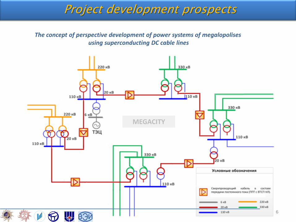
The concept of perspective development of power systems of megalopolises using superconducting DC cable lines
6
Project development prospects
MEGACITY
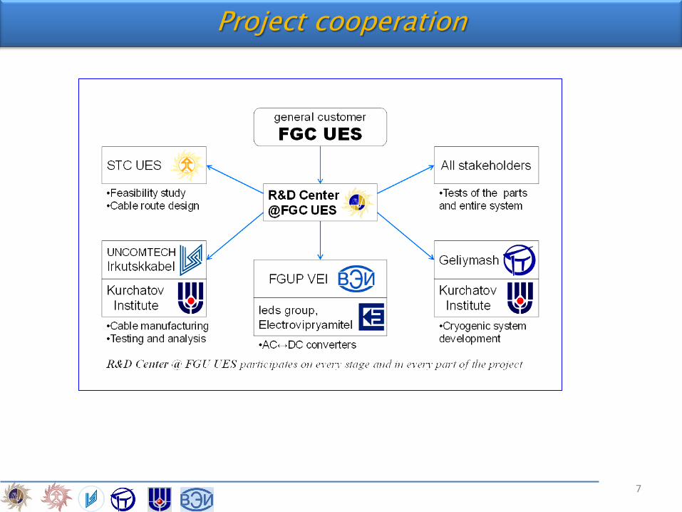
Project cooperation
7
ne
CONTENT
Background
HTS DC Cable Line in St. Petersburg Grid
Cable and cable fittings
Cryogenics
Converter
Testing
Conclusion
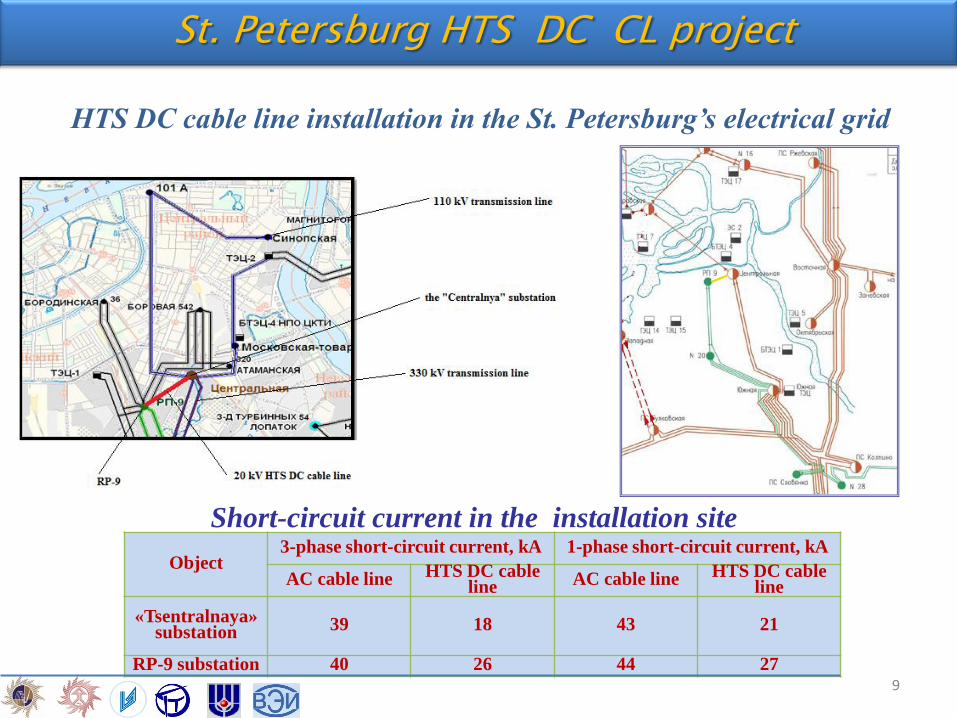
St. Petersburg HTS DC CL project
Object 3-phase short-circuit current, kA 1-phase short-circuit current, kA
AC cable line HTS DC cable line AC cable line HTS DC cable
line
«Tsentralnaya» substation 39 18 43 21
RP-9 substation 40 26 44 27
Short-circuit current in the installation site
HTS DC cable line installation in the St. Petersburg’s electrical grid
9
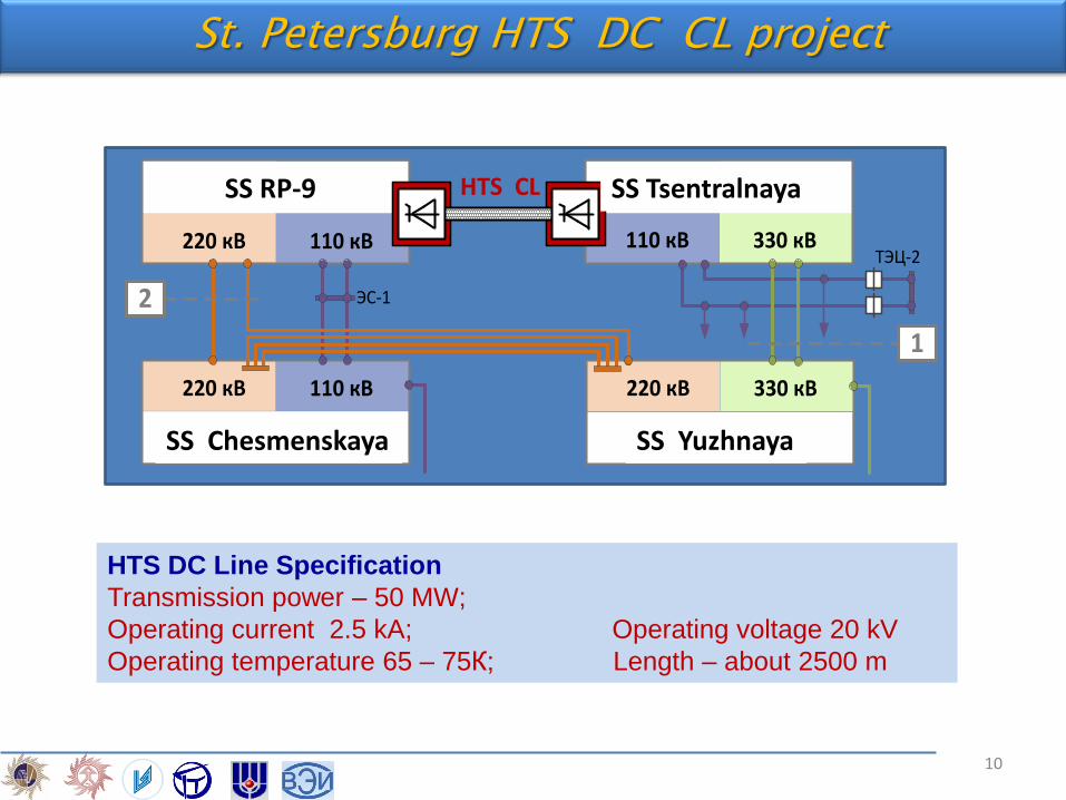
HTS DC Line Specification
Transmission power – 50 MW;
Operating current 2.5 kA; Operating voltage 20 kV
Operating temperature 65 – 75К; Length – about 2500 m
ПС Центральная
110 кВ 330 кВ
РП-9
220 кВ 110 кВ
ПС Чесменская
220 кВ 110 кВ
ПС Южная
220 кВ 330 кВ
ТЭЦ-2
ЭС-1
1
2
SS RP-9 SS Tsentralnaya
SS Yuzhnaya SS Chesmenskaya
HTS CL
St. Petersburg HTS DC CL project
10
11
Comparison of different variants of execution of the links between 330 kV SS “Tsentralnaya” and SS 220 kV RP-9
Current loading of the power lines in areas SS “Tsentralnaya” and SS RP-9 in the post-emergency mode.
Iallowable, А I, А I/Ial, % δР, МW
Enter the cable line 110 kV SS “Tsentralnaya” and SS RP-9
OL 110 kV SS Chesmenskaya – ЭС-1 600 656 109 70
CL 110 kV SS “Tsentralnaya” - SS RP-9 1210 1248 103
Enter HTS DC line capacity of 200 MW
OL 110 kV SS Chesmenskaya – ЭС-1 600 592 98 0
Enter GIL 110 kV
OL 110 kV SS Chesmenskaya – ЭС-1 600 658 110 70
Short-circuit currents in different variants of connections between SS “Tsentralnaya” and SS RP-9
Calculation
points of short-
circuit current
Ibreaking,
кА
HTS DC
Cable line
AC Cable line AC Cable line
+ CLR
GIL
I3,kA I1, kA I3, кА I1, kA I3, кА I1, kA I3,кА I1,kA
Busbar 110 kV
SS“Tsentralaya”
40,0 18,4 20,9 39,2 43,1 21,9 24,6 40,0 43,9
Busbar 110 kV
SS RP-9
31,5 26,4 27,1 40,3 43,9 29,4 30,4 40,7 44,4
St. Petersburg HTS DC CL project
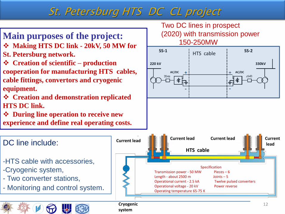
HTS cable
220 kV
Cryogenic system
Current lead Current lead Current lead Current lead DC line include:
-HTS cable with accessories,
-Cryogenic system,
- Two converter stations,
- Monitoring and control system.
HTS cable
AC/DC AC/DC
220 kV
SS-1 SS-2
330kV
Two DC lines in prospect
(2020) with transmission power
150-250MW
Specification Transmission power - 50 MW Pieces – 6 Length - about 2500 m Joints – 5 Operational current - 2.5 kA Twelve pulsed converters Operational voltage - 20 kV Power reverse Operating temperature 65-75 K
Основные элементы кабеля по порядку от центра (показано не все, только то что принципиально важно в данной схеме):1. Медный формер, выполняет больше механическую функцию2. Прямой ВТСП проводник под напряжением 20 кВ, течет ток 2,5 кА3. Бумажная изоляция 20 кВ, постоянное напряжение, толщина примерно 5 мм4. Обратный ВТСП проводник, лежит на нулевом потенциале, через него течет обратный ток 2,5 кА, заземлен с одной стороны5. Тонкий слой бумажной изоляции менее 1 мм, для изоляции возможного наведенного напряжения (напряжение измеряется десятками вольт,
требует уточнения) на незаземленном конце обратного ВТСП проводника от криостата6. Медный/стальной экран, не предназначен для протекания тока, выполняет механическую стабилизирующую функцию и выравнивает
электрическое поле возможного наведенного напряжения на незаземленном конце ВТСП обратного проводника, заземлен с обоих сторон7. Гибкий криостат, заземлен с обоих сторон
Заземление обратного ВТСП проводника с одной стороны, сопротивление заземления требует уточнения
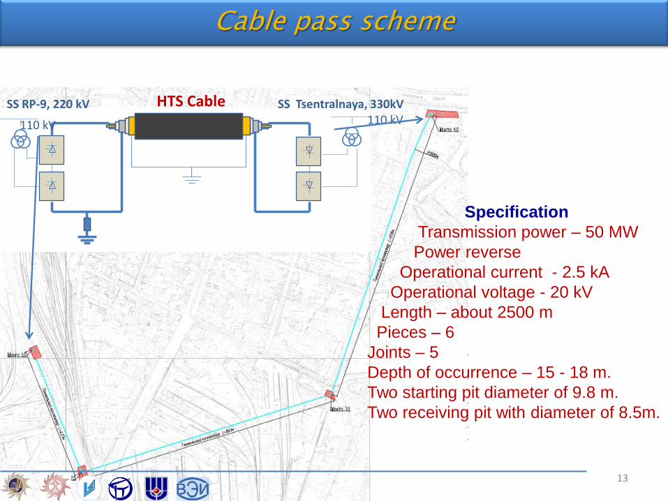
SS RP-9, 220 kV SS Tsentralnaya, 330kV 110 kV 110 kV
HTS Cable
Specification
Transmission power – 50 MW
Power reverse
Operational current - 2.5 kA
Operational voltage - 20 kV
Length – about 2500 m
Pieces – 6
Joints – 5
Depth of occurrence – 15 - 18 m.
Two starting pit diameter of 9.8 m.
Two receiving pit with diameter of 8.5m.
13
Object selection
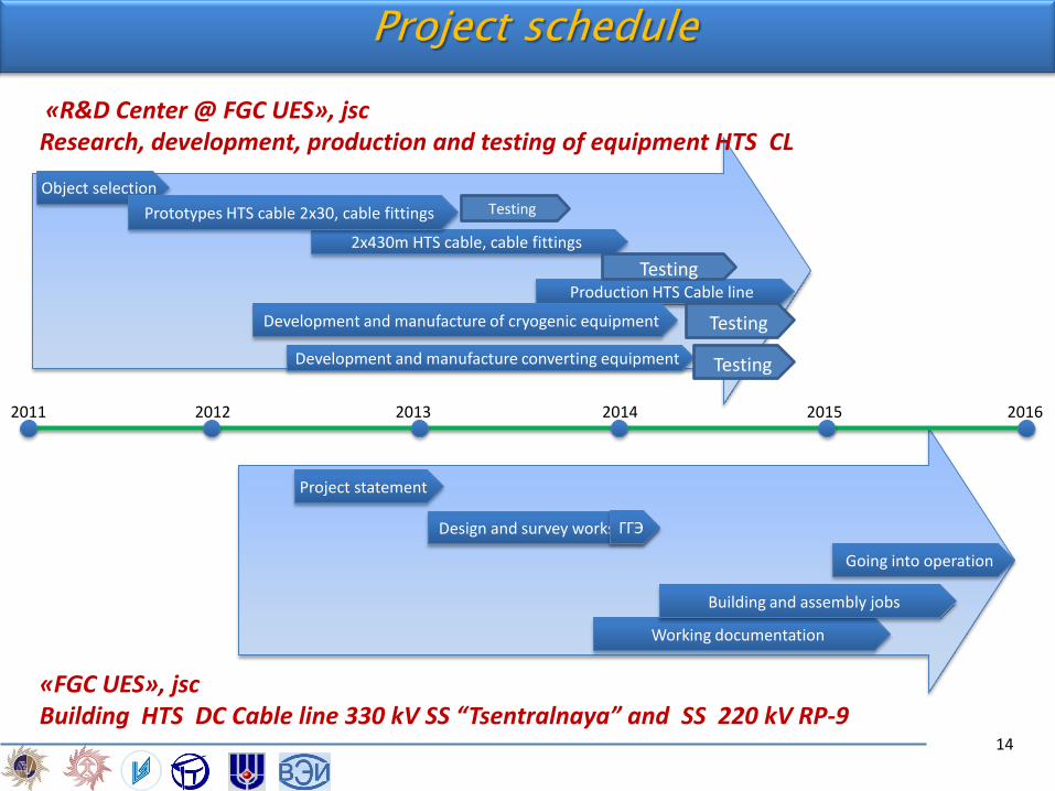
«R&D Center @ FGC UES», jsc Research, development, production and testing of equipment HTS CL
«FGC UES», jsc Building HTS DC Cable line 330 kV SS “Tsentralnaya” and SS 220 kV RP-9
2х430m HTS cable, cable fittings
2011 2012 2013 2014 2015 2016
Development and manufacture converting equipment
Prototypes HTS cable 2х30, cable fittings
Production HTS Cable line
Development and manufacture of cryogenic equipment
Project statement
Design and survey works ГГЭ
Going into operation
Working documentation
Building and assembly jobs
Project schedule
Testing
Testing
Testing
Testing
14
ne
CONTENT
Background
HTS DC Cable Line in St. Petersburg Grid
Cable and cable fittings
Cryogenics
Converter
Testing
Conclusion
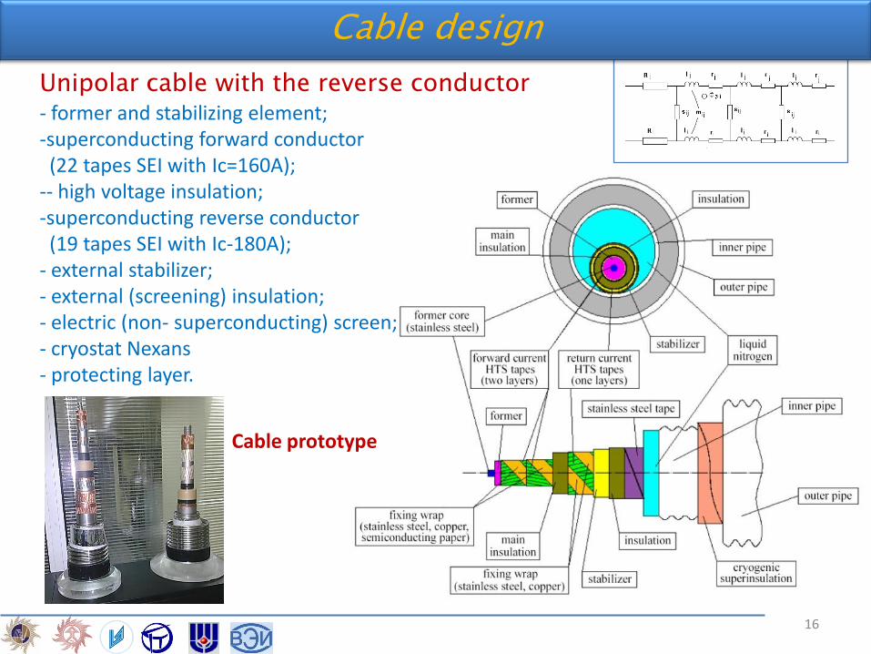
Cable design
Cable prototype
Unipolar cable with the reverse conductor - former and stabilizing element; -superconducting forward conductor (22 tapes SEI with Ic=160A); -- high voltage insulation; -superconducting reverse conductor (19 tapes SEI with Ic-180A); - external stabilizer; - external (screening) insulation; - electric (non- superconducting) screen; - cryostat Nexans - protecting layer.
16
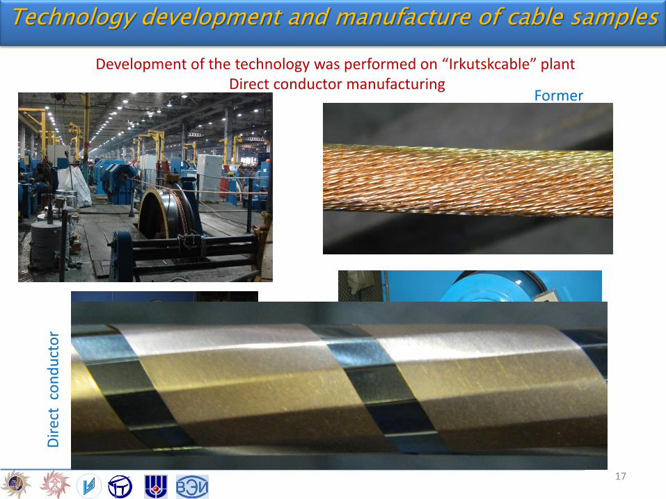
Technology development and manufacture of cable samples
Development of the technology was performed on “Irkutskcable” plant Direct conductor manufacturing
Former
Dir
ect
co
nd
uct
or
17
Technology development and manufacture of cable samples
Application of HV insulation Return conductor manufacturing
18
Technology development and manufacture of cable samples
30 meters samples Application of copper screen
19
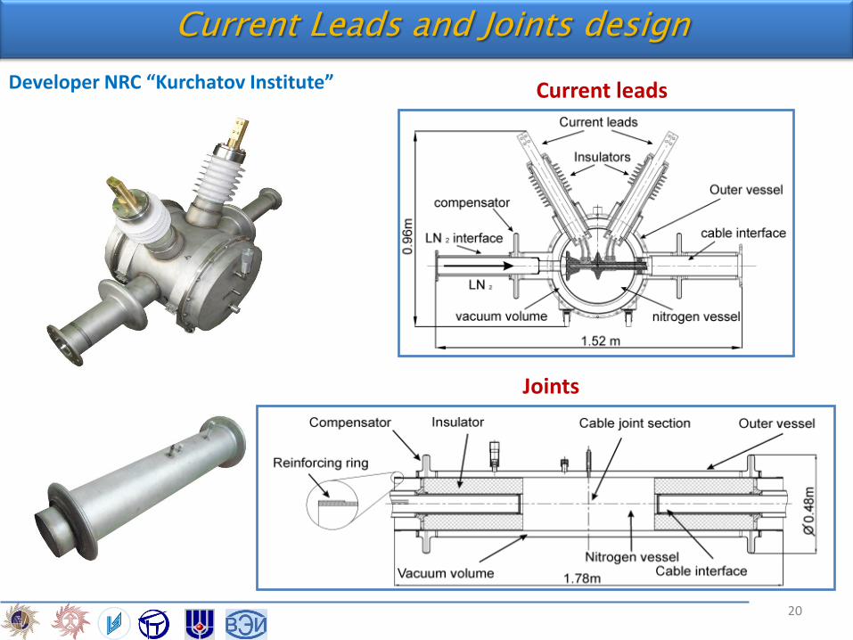
Current Leads and Joints design
Current leads
Joints
Developer NRC “Kurchatov Institute”
20
Current Leads and Joints
Temperature distribution along the brass current lead and heat leakage into the cold zone
Material Brass rod
Length 0.45 meter
Diameter 48 mm
Heat input @ I=0 A 58.5 W
Heat input @ I=2.5 kA (only rod)
113.0 W
0
2x10⁻⁸
4x10⁻⁸
6x10⁻⁸
8x10⁻⁸
0 5 10 15 20 25
Ëåí òà LIX ñ ëàòóí üþ (AMSC)
Ëåí òà ÑÒ-Î Ð 22-80, Sumitomo
Äëèí à êî í òàêòà, ñì
Ñî
ïð
îòè
âë
åí
èå
êî
íòà
êòà
, Î
ì
Tape LIX (AMSC) Tape CT-OP (Sumitomo)
Joint length, cm
Join
t re
sist
ance
, Oh
m
Soldered joints resistance
21
ne
CONTENT
Background
HTS DC Cable Line in St. Petersburg Grid
Cable and cable fittings
Cryogenics
Converter
Testing
Conclusion
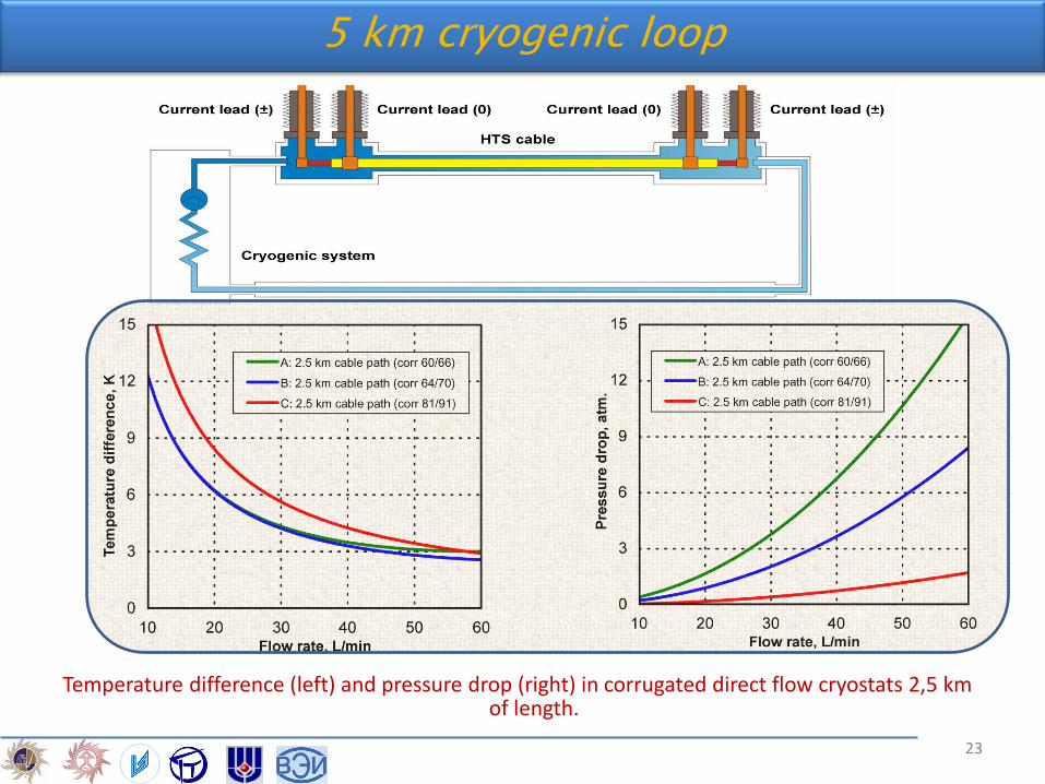
Temperature difference (left) and pressure drop (right) in corrugated direct flow cryostats 2,5 km of length.
5 km cryogenic loop
23
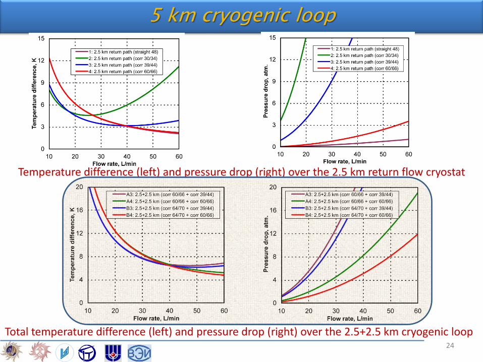
5 km cryogenic loop
Temperature difference (left) and pressure drop (right) over the 2.5 km return flow cryostat
Total temperature difference (left) and pressure drop (right) over the 2.5+2.5 km cryogenic loop 24
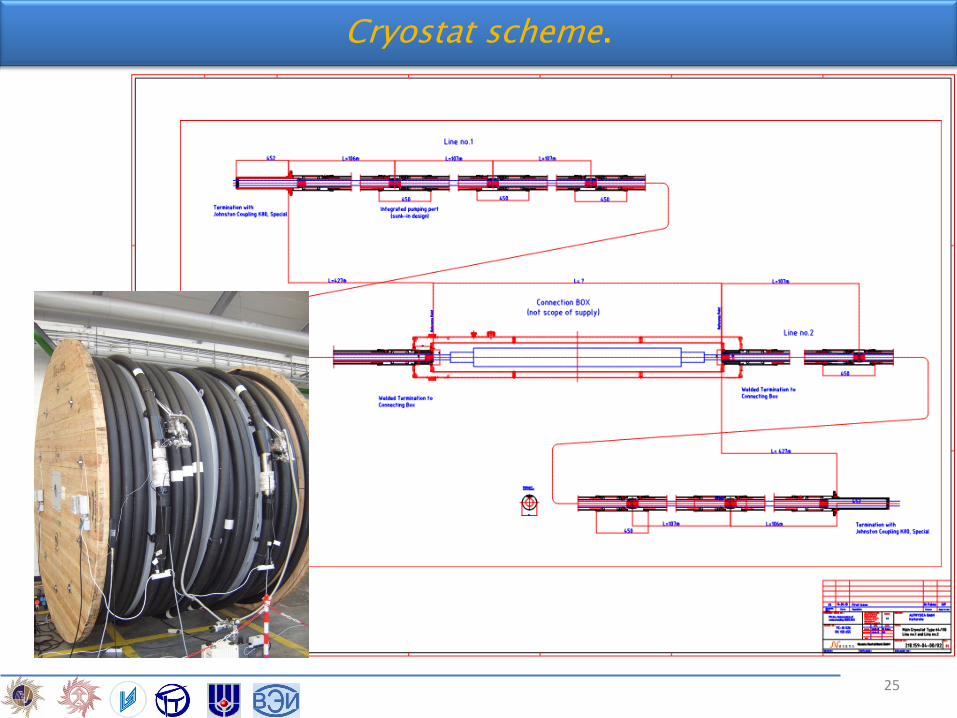
Cryostat scheme.
25
He
lium
Low pressure Turbo - Brayton system
Liquid nitrogen
Liquid nitrogen container
Helium
Hel
ium
Diagram of the cryogenic system.
Cooling capacity – 12 kW @ 70K Pressure LN – up to 1.4MPa Temperature 66– 80 K Mass flow - up to 45 L/min
26
ne
CONTENT
Background
HTS DC Cable Line in St. Petersburg Grid
Cable and cable fittings
Cryogenics
Converter
Testing
Conclusion
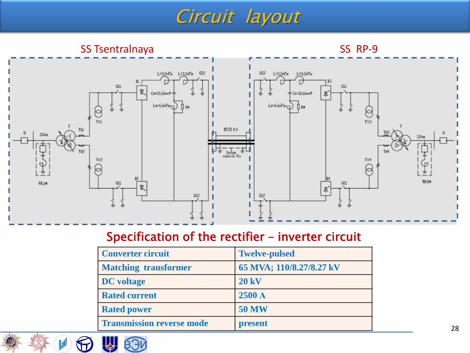
Circuit layout
Converter circuit Twelve-pulsed
Matching transformer 65 MVA; 110/8.27/8.27 kV
DC voltage 20 kV
Rated current 2500 А
Rated power 50 MW
Transmission reverse mode present
Specification of the rectifier – inverter circuit
SS Tsentralnaya SS RP-9
28
№ Harmonics
1 =150;=200;
Id=2500 A I12~0, I24=4 A
2 =150;=30;
Id=200 A I12~0, I24=2 A
3 =800;=10;
Id=250 A I12~0, I24=7 A
Lp/2= 3,2 mH Cф= 10,66 µF Lф= 6,6 mH Qpl = 120 kW
DC filter and current harmonics
Operating mode
29
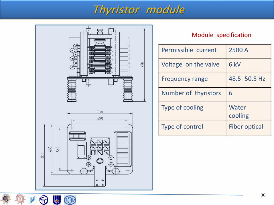
Thyristor module
Module specification
Permissible current 2500 A
Voltage on the valve 6 kV
Frequency range 48.5 -50.5 Hz
Number of thyristors 6
Type of cooling Water cooling
Type of control Fiber optical
30
ne
CONTENT
Background
HTS DC Cable Line in St. Petersburg Grid
Cable and cable fittings
Cryogenics
Converter
Testing
Conclusion
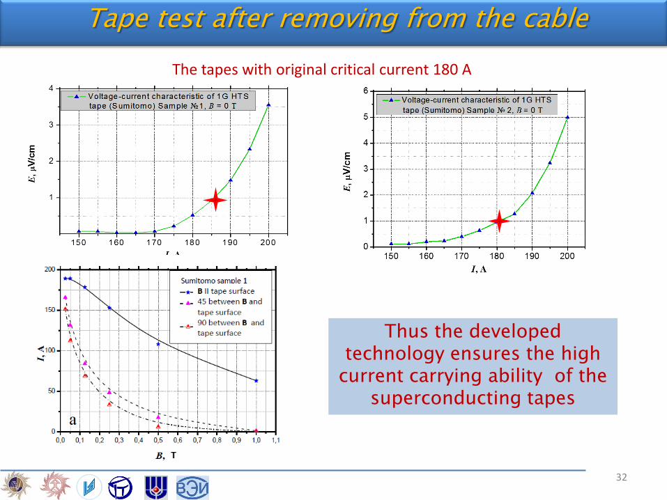
Tape test after removing from the cable
The tapes with original critical current 180 A
Thus the developed technology ensures the high
current carrying ability of the superconducting tapes
32
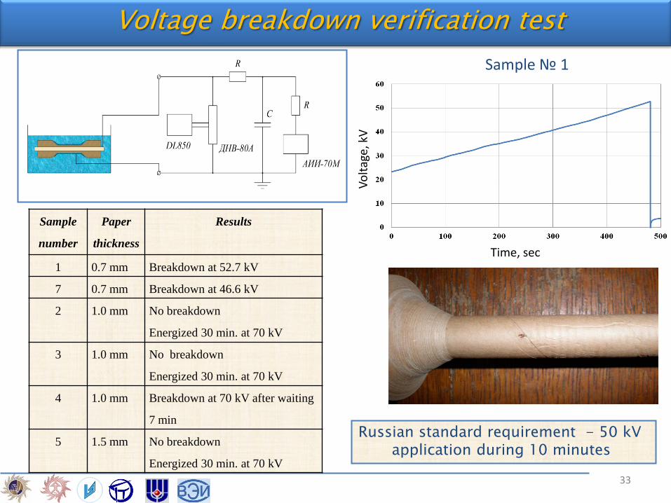
Voltage breakdown verification test
Russian standard requirement - 50 kV application during 10 minutes
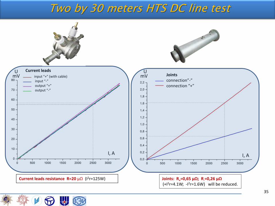
Joints: R+=0,65 μΩ; R-=0,26 μΩ (+I2r=4.1W; -I2r=1.6W) will be reduced.
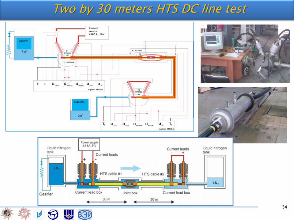
Two by 30 meters HTS DC line test
35
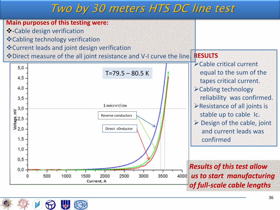
Reverse conductors
Direct c0nductor
RESULTS Cable critical current equal to the sum of the tapes critical current. Cabling technology reliability was confirmed. Resistance of all joints is stable up to cable Ic. Design of the cable, joint and current leads was confirmed
Main purposes of this testing were: -Cable design verification Cabling technology verification Current leads and joint design verification Direct measure of the all joint resistance and V-I curve the line.
T=79.5 – 80.5 K
Two by 30 meters HTS DC line test
Results of this test allow us to start manufacturing of full-scale cable lengths
36
Experimental facility for superconducting devices testing at the R&D Center @ FGC UES
1 - HTS cable
2, 3, 6, 7, 17, 20
– Cryogenic system
4 – Current leads
5, 11, 12, 16, 18, 21, 22 – Facility power system
8, 9 – Facility control center
10 – DC current source
13, 14, 15 – Air compartment
19 - Load
37
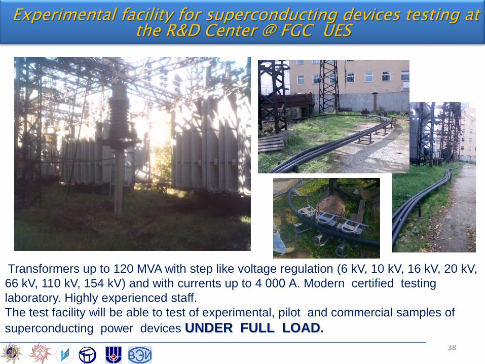
Transformers up to 120 MVA with step like voltage regulation (6 kV, 10 kV, 16 kV, 20 kV,
66 kV, 110 kV, 154 kV) and with currents up to 4 000 А. Modern certified testing
laboratory. Highly experienced staff.
The test facility will be able to test of experimental, pilot and commercial samples of
superconducting power devices UNDER FULL LOAD.
Experimental facility for superconducting devices testing at the R&D Center @ FGC UES
38
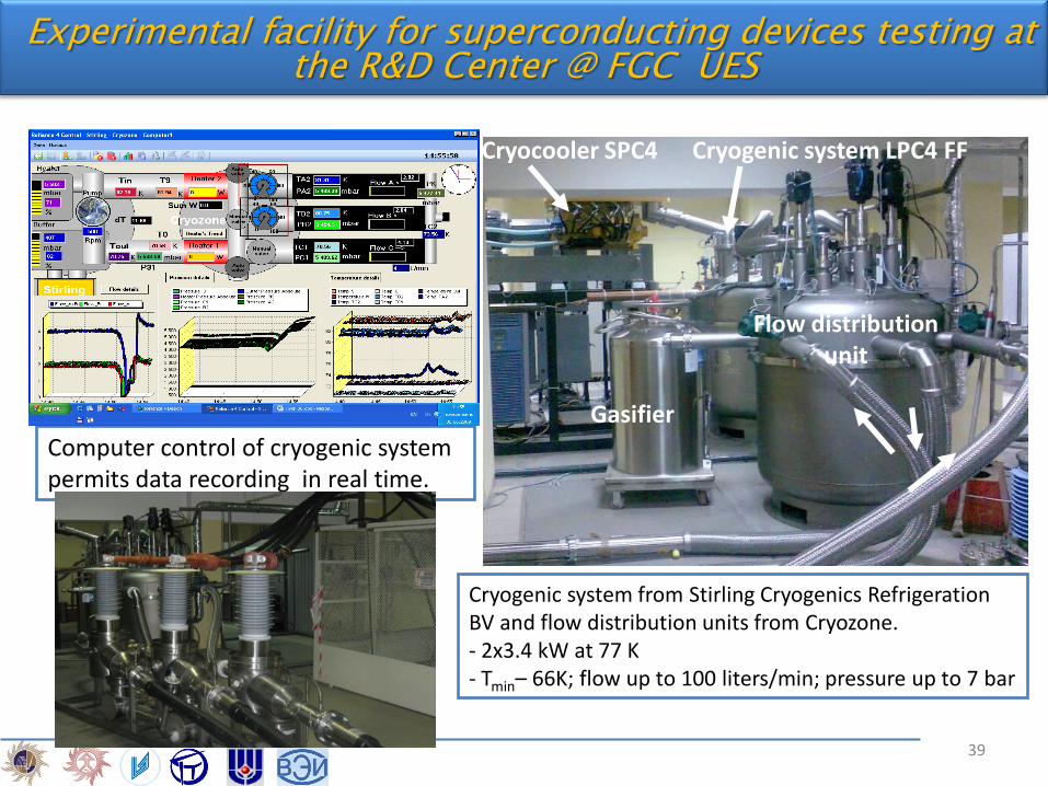
Computer control of cryogenic system permits data recording in real time.
Cryocooler SPC4 Cryogenic system LPC4 FF
Gasifier
Flow distribution unit
Cryogenic system from Stirling Cryogenics Refrigeration BV and flow distribution units from Cryozone. - 2x3.4 kW at 77 K - Tmin– 66K; flow up to 100 liters/min; pressure up to 7 bar
Experimental facility for superconducting devices testing at the R&D Center @ FGC UES
39
Conclusions
Combination of two technologies: superconductivity and DC transmission bring a new quality to the megalopolises network. The HTS DC cable line installation improves the reliability of energy supply to the consumers by mutual redundancy grid sectors and enhancement of controllability of the link. Along with this, it does not increase short-circuit currents. St. Petersburg Project is carried out in accordance with the schedule. All units of equipment have been developed. Successful tests of 2 x 30 m. cable samples allowed to start manufacturing of full-scale cable length. The successful introduction of this HTS DC CL into the St. Petersburg electric power system will allow checking up the basic technical solutions for this technology and get an experience for the commercial application. It will be first step for the further building of circular DC electric power chain in megalopolises.